Embed Size (px)
Citation preview
Mousebuster: A Robot for Real-Time Catching
Giorgio C. Buttazzo, Benedetto Allotta, and Felice P. Fanizza
control methodology for catching a fast moving object with a robot manipulator, where visual information is employed
to track the trajectory of the target, is described here. Sensing, planning, and control are performed in real time to cope with possible unpredictable trajectory changes of the moving target, and prediction techniques are adopted to compensate the time delays introduced by visual processing and by the robot control- ler. A simple but reliable model of the robot controller has been taken into account in the control architecture for improving the performance of the system. Experimental results have shown that the robot system is capable of tracking and catching an object moving on a plane at velocities of up to 700 mm/s and accelera- tions of up to 1500 mm/s2.
Visual Tracking Catching a moving object with one hand is one of the most
difficult tasks for humans as well as for robot systems. In order to perform this task, several capabilities are required of a robot system, such as smart sensing, object tracking, motion predic- tion, trajectory planning, and fine sensory-motor coordination. If the moving target is an intelligent being, like a fast insect or a little mouse, the problem becomes more difficult to solve, since the “prey” may unexpectedly modify its trajectory, velocity, and acceleration. In this situation, sensing, planning, and control must be performed in real time while the target is moving, so that the trajectory of the arm can be modified in time to catch the prey.
The problem of visual tracking has been widely investigated in the robotics literature. Corke et ul. [13], [I41 addressed the issue of high performance visual servoing for an arm-mounted camera. Feddema et al. [IS], [ 161 investigated the problem of feature-based control for the tracking of a moving target by a robot-camera system. Papanikolopoulos et al. [2 11 proposed some methods for tracking selected features of a moving target with a mobile camera. Anderson [7] analyzed the use of visual sensing in dynamic environments, i.e., changing at rates compa- rable to the rates of the robot system. Weiss e t d . [23] used visual information to control a robot arm for manipulation. In addition to tracking capabilities, catching a moving object also requires predicting the object motion and local planning of the arm trajectory based on sensor information. Hayward et al. [17] described a method for obtaining smooth trajectories suitable to be tracked by a servo control system, based on sensory preview.
~~
Bused on a paper [ I 21 preseritrd at the I993 Iriternational Confer- ence on Robotics arid Automatioii. Atlanta, GA, M o y 2-6 , 1993. The authors ure Mith the A.R.T.S. Luboratoiy of the Smola Superiore S. Anna, Pisa, Italy. This M w k MYLS partly supported by the Special Project on Robotics qf’the National Research Co~rncil ofl taly.
m
Lloyd and Hayward [20] derived a technique for blending path segments while controlling the transition shape. Anderson [6] designed a trajectory generation system to maximize the manipu- lator’s usable performance in a robot Ping-Pong player. The issue of high performance hand-eye coordination is also reported in 111, [SI, [22], where the problem of robot juggling has been considered. Grasping a moving target with a robot arm has been approached by [2], [3], [8], 1181. Allen et al. split the control algorithm in two steps: a filtering and prediction phase, during which the robot tracks the object motion with the desired preci- sion, and a catching phase, in which the robot is driven toward the target as fast as possible. While in Allen’s approach, once the grasping phase is started the arm trajectory cannot be modified, in the present work, we propose a method for real-time planning of grasping trajectory based on sensor information. Moreover, a
February 1994 0272- 1708/94/$04.000 1994IEEE 49
simple but reliable model of the robot controller has been taken into account in the control architecture for improving the system response. To address the problem of catching a moving object with a robot manipulator, we have initially simplified and for- malized the task by making the following assumptions:
a. The object trajectory lies on a known plane within the robot workspace.
b. The object is free to change the velocity and the acceleration of its motion in both directions of the plane, at any time.
c. The catch is done by trapping the object in a bowl-shaped end-effector, with a radius of 40 mm. which is almost equal to the object length.
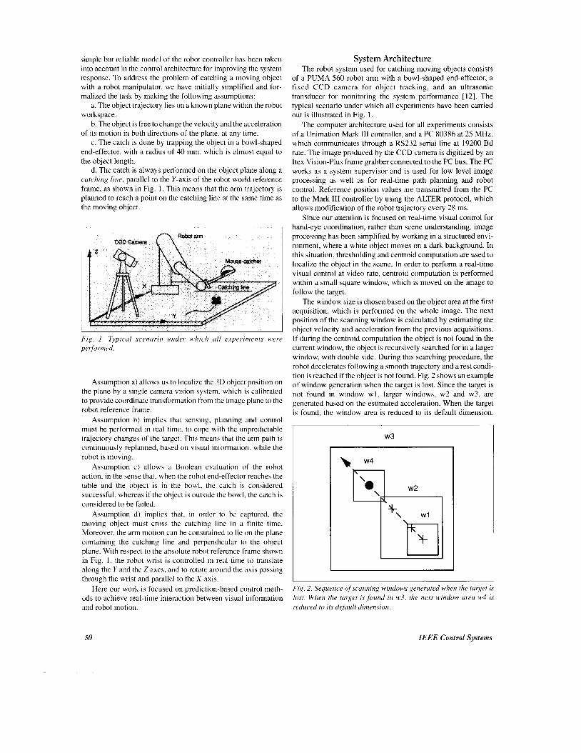
d. The catch is always performed on the object plane along a catching line, parallel to the Y-axis of the robot world reference frame, as shown in Fig. 1. This means that the arm trajectory is planned to reach a point on the catching line at the same time as the moving object.
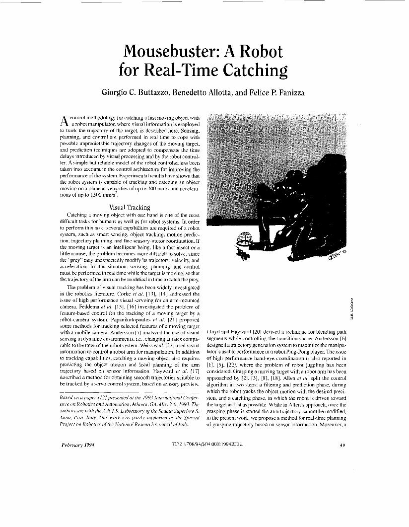
Fig. I . Typical scenario under which all e,ipcvrments were perjbmed.
Assumption a) allows us to localize the 3D object position on the plane by a single camera vision system. which is calibrated to provide coordinate transformation from the image plane to the robot reference frame.
Assumption b) implies that sensing. planning and control must be performed in real time, to cope with the unpredictable trajectory changes of the target. This means that the arm path is continuously replanned, based on visual information. while the robot is moving.
Assumption c ) allows a Boolean evaluation of the robot action. in the sense that, when the robot end-effector reaches the table and the object is in the bowl, the catch is considered successful, whereas if the object is outside the bowl, the catch is considered to be failed.
Assumption d) implies that. in order to be captured, the moving object must cross the catching line in a finite time. Moreover, the arm motion can be constrained to lie on the plane containing the catching line and perpendicular to the object plane. With respect to the absolute robot reference frame shown in Fig. 1, the robot wrist is controlled in real time to translate along the Y and the Z axes, and to rotate around the axis passing through the wrist and parallel to the X-axis.
Here our work is focused on prediction-based control meth- ods to achieve real-time interaction between visual information and robot motion.
System Architecture The robot system used for catching moving objects consists
of a PUMA 560 robot arm with a bowl-shaped end-effector, a fixed CCD camera for object tracking, and an ultrasonic transducer for monitoring the system performance [ 121. The typical scenario under which all experiments have been carried out is illustrated in Fig. 1.
The computer architecture used for all experiments consists of a Unimation Mark 111 controller, and a PC 80386 at 25 MHz, which communicates through a RS232 serial line at 19200 Bd rate. The image produced by the CCD camera is digitized by an Itex Vision-Plus frame grabber connected to the PC bus. The PC works as a system supervisor and is used for low level image processing as well as for real-time path planning and robot control. Reference position values are transmitted from the PC to the Mark I11 controller by using the ALTER protocol, which allows modification of the robot trajectory every 28 ms.
Since our attention is focused on real-time visual control for hand-eye coordination, rather than scene understanding, image processing has been simplified by working in a structured envi- ronment, where a white object moves on a dark background. In this situation, thresholding and centroid computation are used to localize the object in the scene. In order to perform a real-time visual control at video rate, centroid computation is performed within a small square window, which is moved on the image to follow the target.
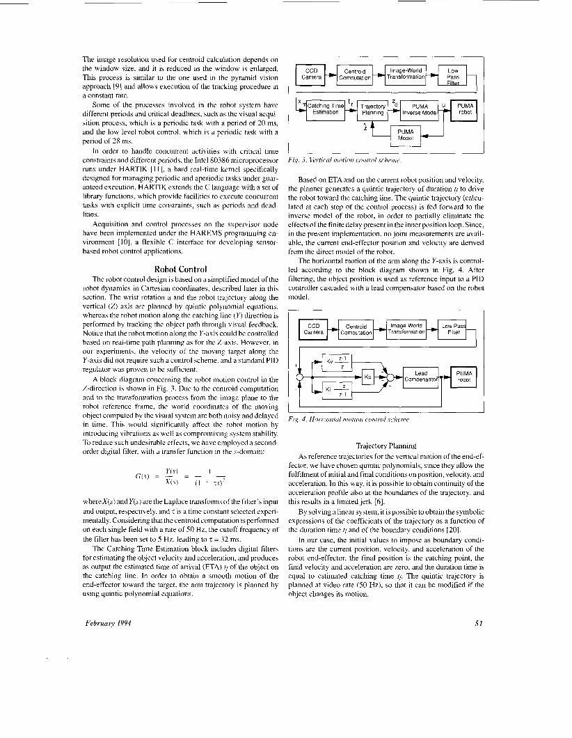
The window size is chosen based on the object area at the first acquisition, which is performed on the whole image. The next position of the scanning window is calculated by estimating the object velocity and acceleration from the previous acquisitions. If during the centroid computation the object is not found in the current window, the object is recursively searched for in a larger window, with double side. During this searching procedure, the robot decelerates following a smooth trajectory and a rest condi- tion is reached if the object is not found. Fig. 2 shows an example of window generation when the target is lost. Since the target is not found in window w l , larger windows, w2 and w3, are generated based on the estimated acceleration. When the target is found. the window area is reduced to its default dimension.
w3
Fi,?. 2 . Sequence ofscanning windows generated when the target is lost. When the target is found in w3, the next window area w14 is ruduc~ed to its default dimension.
50 IEEE Control Systems
The image resolution used for centroid calculation depends on the window size, and it is reduced as the window is enlarged. This process is similar to the one used in the pyramid vision approach [9] and allows execution of the tracking procedure at a constant rate.
Some of the processes involved in the robot system have different periods and critical deadlines, such as the visual acqui- sition process, which is a periodic task with a period of 20 ms, and the low level robot control, which is a periodic task with a period of 28 ms.
In order to handle concurrent activities with critical time constraints and different periods, the Intel 80386 microprocessor runs under HARTIK [ 1 11, a hard real-time kemel specifically designed for managing periodic and aperiodic tasks under guar- anteed execution. HARTIK extends the C language with a set of library functions, which provide facilities to execute concurrent tasks with explicit time constraints, such as periods and dead- lines.
Acquisition and control processes on the supervisor node have been implemented under the HAREMS programming en- vironment [lo], a flexible C interface for developing sensor- based robot control applications.
Robot Control The robot control design is based on a simplified model of the
robot dynamics in Cartesian coordinates, described later in this section. The wrist rotation a and the robot trajectory along the vertical (2) axis are planned by quintic polynomial equations, whereas the robot motion along the catching line ( r ) direction is performed by tracking the object path through visual feedback. Notice that the robot motion along the Y-axis could be controlled based on real-time path planning as for the Z-axis. However, in our experiments, the velocity of the moving target along the Y-axis did not require such a control scheme, and a standard PID regulator was proven to be sufficient.
A block diagram conceming the robot motion control in the Z-direction is shown in Fig. 3. Due to the centroid computation and to the transformation process from the image plane to the robot reference frame, the world coordinates of the moving object computed by the visual system are both noisy and delayed in time. This would significantly affect the robot motion by introducing vibrations as well as compromising system stability. To reduce such undesirable effects, we have employed a second- order digital filter. with a transfer function in the s-domain:
Estimation -W Planning -+ Inverse Model
whereX(s) and Y(s) are the Laplace transforms of the filter’s input and output, respectively, and z is a time constant selected experi- mentally. Considering that the centroid computation is performed on each single field with a rate of 50 Hz, the cutoff frequency of the filter has been set to 5 Hz, leading to z = 32 ms.
The Catching Time Estimation block includes digital filters for estimating the object velocity and acceleration, and produces as output the estimated time of arrival (ETA) ff of the object on the catching line. In order to obtain a smooth motion of the end-effector toward the target, the arm trajectory is planned by using quintic polynomial equations.
robot
February 1994
+ +
+
Centroid Low Pass Filter
Kv 2 z
Lead PUMA Compensatoi- robot
Ki 2-1
I I I
; tqPUMAI_I Model
Fig. 3. I/rrtical motion control scheme.
Based on ETA and on the current robot position and velocity, the planner generates a quintic trajectory of duration to drive the robot toward the catching line. The quintic trajectory (calcu- lated at each step of the control process) is fed forward to the inverse model of the robot, in order to partially eliminate the effects of the finite delay present in the inner position loop. Since, in the present implementation, no joint measurements are avail- able, the current end-effector position and velocity are derived from the direct model of the robot.
The horizontal motion of the arm along the Y-axis is control- led according to the block diagram shown in Fig. 4. After filtering, the object position is used as reference input to a PID controller cascaded with a lead compensator based on the robot model.
CCD Centroid Camera *~Computatlon -Transformation
Fig. 4 . Hor.i:onral morion cwitrol s c h v n t ~
Trajectory Planning As reference trajectories for the vertical motion of the end-ef-
fector, we have chosen quintic polynomials, since they allow the fulfilment of initial and final conditions on position, velocity, and acceleration. In this way, it is possible to obtain continuity of the acceleration profile also at the boundaries of the trajectory, and this results in a limited jerk [6].
By solving a linear system, it is possible to obtain the symbolic expressions of the coefficients of the trajectory as a function of the duration time ?and of the boundary conditions [20].
In our case, the initial values to impose as boundary condi- tions are the current position, velocity, and acceleration of the robot end-effector, the final position is the catching point, the final velocity and acceleration are zero, and the duration time is equal to estimated catching time ~f: The quintic trajectory is planned at video rate (50 Hz), so that it can be modified if the object changes its motion.
5 1
Aproblem that we have found with quintic trajectories, is that, for particular values of the catching time, the robot path would cross the object plane for reaching the catching point within the
acceptable in free space motion, it must be absolutely avoided when the ending point lies on a rigid plane.
we have Seen that to maintain the robot trajectory above the object plane, a positive jerk must be imposed at time (t; which implies the following constraint on the final acceleration af:
Under the above assumptions, the shortest positive value of the arrival time tfis given by:
(5)
For very low acceleration, the catching time tfcan be computed by assuming a Constant velocity trajectory:
specified boundary conditions. Although this situation could be d&TZF - l',), I f = ~
ani
.\] = .t',! + l"t/ (6)
where zi, \'i, and a, are the current robot position, velocity, and acceleration, zfis the ending point on the catching line, and tf is the trajectory duration time.
If the estimated time is too short, Le., the object is moving too fast, the velocity or the acceleration required to the robot for catching the object could overcome the maximum values allowed to the system. In this case, the robot stops moving and gives up doing the action.
On the other hand, when the estimated time is too long, meaning that the object is not moving, the arm stops too, waiting for the object to approach the catching line.
Catching-Time Estimation
D f f = -
Vnr ( 7 )
The estimated time ti is used to plan the robot trajectory so that the catching point is reached by the end-effector exactly at time q. Notice that, in order for the catch to be feasible, the time necessary to execute the quintic trajectory must comply with the velocity and acceleration limits of the robot. In fact, let us consider the case of a robot at height H from the catching line, driven along a quintic trajectory with boundary conditions 1, = H, and zf= v; = \y = a; = q= 0. If Vmax and Amax are the velocity and acceleration limits of the robot, the minimum time needed for executing the quintic trajectory is given by:
To trap the moving object in a point on the catching line, the
by the end-effector at the same time as the object. This can be achieved by observing the object motion and estimating, at any instant, the time needed by the object to cross the target line. Note
robot has to plan a trajectory so that the catching point is reached t h i n = max ( t f l . tt;) (8)
where
IS H If, . = ___
8 ~'",,, that, since nothing is assumed on the object trajectory, path estimation and time calculation must be performed in real time
the maximum velocity and acceleration assumed for the object. at a proper frequency, depending on the robot bandwidth, and on
In order to find an algebraic condition under which the catch is guaranteed, we assume that the object moves with constant acceleration, so that its position x,,, changes in time according to:
rt, = A , n u
Therefore, the condition under which the catching is guaranteed is given by the following expressions:
where xd, \',,a, and a d are the object position, velocity, and acceleration at time t = to. Thus, at any instant, the time ?needed by the object to reach the catching point .y = s,?,(?) is derived by d~,;, + 20,,D - I ' ~ ~ ,
(10)
where (9) applies for negligible object accelerations and ( I O )
In order to test the efficiency of the catching-time estimation algorithm when the acceleration of the target is not constant, we have executed the algorithm by simulating a trajectory of an object moving with increasing acceleration (at constant jerk). The simulation has been carried out assuming a Gaussian noise with a standard deviation of 0.31 mm. The results are then compared with the case of an object moving with constant
> t h i n imposing: ani
1 7 .t-t = .Ynr + I.,,ff + -u,,q 2 (3) applies in the other cases.
with x,, I", and a, the current object position, velocity, and acceleration. Supposing the object at a distance D = -47 - X ~ I from the catching line, measured along the X-axis, it will cross the catching line if I" > 0, and
2 a,, 2 -%
2 0 . (4) acceleration.
52 IEEE Control Systems
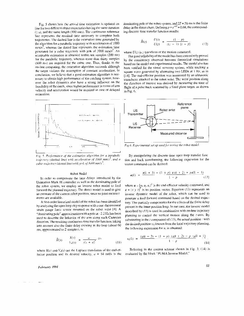
Fig. 5 shows how the arrival time estimation is updated on line for two different object trajectories having the same duration (1 s), and the same length (500 mm). The continuous reference line represents the residual time necessary to complete both trajectories. The dashed line is the estimation time generated by the a1 orithm for a parabolic trajectory with acceleration of 1000 mm/s , whereas the dotted line represents the estimation time generated for a cubic trajectory with jerk of 3000 mm/s3. An acceptable estimation is obtained within ten samples (200 ms) for the parabolic trajectory, whereas more than thirty samples (600 ms) are required for the cubic one. Thus, thanks to the on-line computing, the estimation algorithm succeeds although the target violates the assumption of constant acceleration. In conclusion, we believe that a good estimation algorithm is nec- essary to obtain high performance of the catching system, how- ever the robot dynamics also have a strong influence on the feasibility of the catch, since higher performance in terms of arm velocity and acceleration would be required in case of delayed estimation.
9
dominating pole of the robot system, and 2T = 56 ms is the finite delay in the direct chain. Definingp = KaT= 0.68, the correspond- ing discrete-time transfer function results:
where U ( z ) is ;-transform of the motion command. The good reliability of the model has been extensively proved
by the consistency observed between theoretical simulations based on the model and experimental results. The model also has been verified for the visual servoing system, while tracking a square wave generated by altemating two LEDs at 1 Hz, as in [14]. The end-effector position was monitored by an ultrasonic transducer attached to the robot wrist. The wrist position along the direction of interest was derived by measuring the time of flight of a pulse back scattered by a fixed plane target, as shown in Fig. 6.
I ' I I lINl Reference
I
- - - - _ _ _ _ - _ _ _ - - - - us
I Measured distance
Fig 6 . Experimental set up used for testing the robot model
Fig. 5. Perlf"rmanc,e of the estimation algorithm for a parabolic trajectory (dashed line) Mith acceleration of I000 mmls'. and a c,uhir trajectory (dotted line) Mith jerk of3000 mmls'.
By manipulating the discrete-time open-loop transfer func- tion and back transforming, the following expression for the vector command can be derived:
Robot Model In order to compensate the time delays introduced by the
Unimation Mark 111 controller as well as the dominating pole of the robot system, we employ an inverse robot model to feed forward the planned trajectory. The direct model is used to give an estimate of the current robot position, since no joint measure- ments are available.
A first-order linearized model of the robot has been identified by analyzing the open loop step response with a one-dimensional strain gauge force sensor mounted on the robot wrist [4]. A "dominating pole" approximation with a pole at -2.2 Hz has been used to describe the behavior of the arm along each Cartesian direction. The resulting continuous-time transfer function, taking into account also the finite delay existing in the loop (about 60 ms, approximated to 2 samples), is:
where X ( s ) and Vd(s) are the Laplace transforms of the end-ef- fector position and its desired velocity, a = 14 rad/s is the
x(k + 3) - (1 + p ) x ( k + 2) + px(k + I )
1 - P (13) u(k) =
where u = [u , uv u,]' is the end-effector velocity command, and x = [x y : IT is its position vector. Equation (1 3) represents an inverse dynamic model of the robot, which can be used to generate a feed-forward command based on the desired trajec- tory. This partially compensates for the effects of the finite delay present in the inner position loop. In our case, the inverse model described by (1 3) is used in combination with on-line trajectory planning to control the vertical motion along the z-axis. By substituting in the z component of (1 3), the actual position I with the desired position z d , known from the local trajectory planning, the following expression for u; is obtained:
z& + 3) - (1 + p) a ( k + 2) + p Z d ( k + I )
I - P 14:(k) =
(14)
Referring to the control scheme shown in Fig. 3, (14) is evaluated by the block "PUMA Inverse Model."
February 1994 53
The block “Lead Compensator” shown in Fig. 4 is charac- terized by the following transfer function in the z-domain:
Cascading C(z) with the robot model expressed in (12) results in a transfer function which is equivalent to an integrator with a delay of three samples:
Experimental Results The experiments described here have been carried out with
the robot system described in the second section, and shown in Fig. 1. The CCD camera was mounted approximately 1 m above the object plane, pointing down at an angle of about 40” from the horizontal plane. The camera was directly calibrated with respect to the robot reference frame by using seven reference points obtained by displacing a mark on the robot end-effector. With this calibration method, the three-dimensional points lying on the object plane in the area of interest were determined with an error of 2-3 mm.
In order to meet the real-time requirements, centroid compu- tation was speeded up by employing a pyramid-based tracking algorithm on thresholded images, as outlined in the second section. The measured centroid computation time was found to be about 5 ms in a window of 40x40 pixels. corresponding to an average area of 50x50 mm2.
In the experiments, the catching performance of the robot system was tested by using a ping-pong ball glued on a rigid stick moved by hand on arbitrary trajectories. The ball was moved at velocities of up to 700 mm/s, with accelerations of up to 1500 mm/s2. In addition, we tested the system with a model train moving along a curved track, and with a spring-loaded toy mouse, capable of reaching faster speeds. In all experiments, the bowl-shaped end-effector was standing 160 mm above the catch- ing line that was fixed at .y= 120 mm with respect to the robot reference frame.
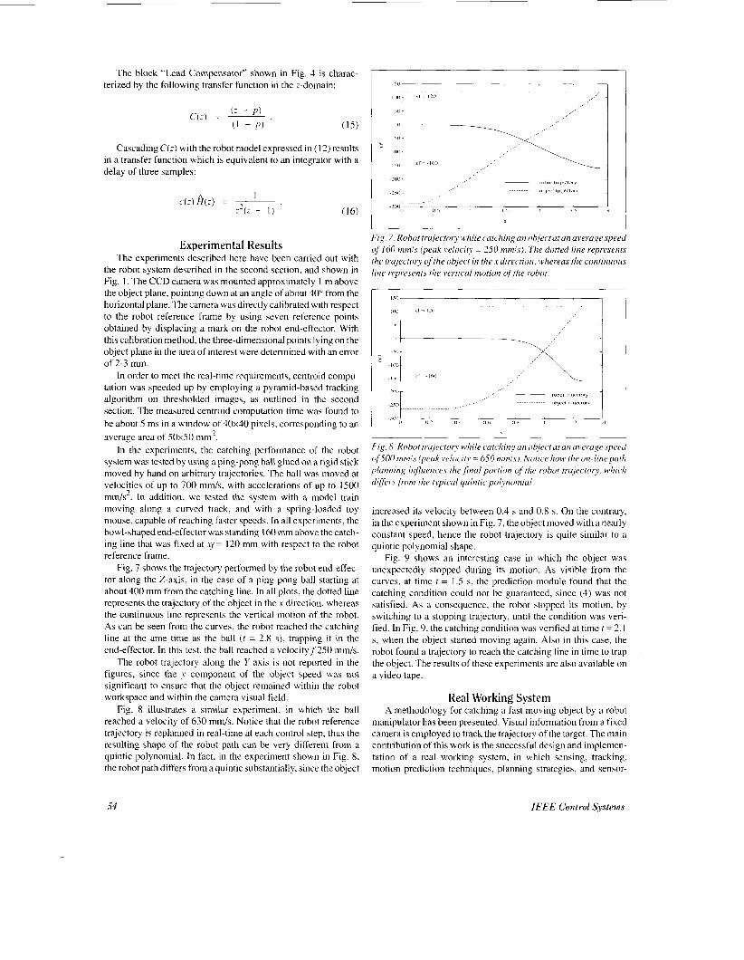
Fig. 7 shows the trajectory performed by the robot end-effec- tor along the Z-axis. in the case of a ping-pong ball starting at about 400 mm from the catching line. In all plots, the dotted line represents the trajectory of the object in the .Y direction, whereas the continuous line represents the vertical motion of the robot. As can be seen from the curves, the robot reached the catching line at the ame time as the ball ( t = 2.8 s), trapping it in the end-effector. In this test, the ball reached a velocityf’250 mm/s.
The robot trajectory along the Y-axis is not reported in the figures, since the y component of the object speed was not significant to ensure that the object remained within the robot workspace and within the camera visual field.
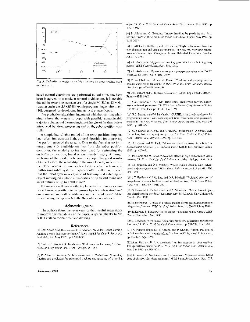
Fig. 8 illustrates a similar experiment, in which the ball reached a velocity of 630 mm/s. Notice that the robot reference trajectory is replanned in real-time at each control step, thus the resulting shape of the robot path can be very different from a quintic polynomial. In fact, in the experiment shown in Fig. 8, the robot path differs from a quintic substantially, since the object
E
Fig. 7. Robot trajectory while catc,hitig an object at on average speed of160 mmls (peak veloci5 = 250 “1s). The dotted line represents the trajectory of the object in the s direction, u1herea.s the continuous line represents the wrtic.al motion oj‘the robot
Fig. 8. Robot trajectory while catchitq an object at an average speed of500 mmls (peak veloc.ity = 650 mnils). Notice hoM. the on-line path planning influences the final portion of the robot trajectory. which differs from the typical quintic, polynomial.
increased its velocity between 0.4 s and 0.8 s. On the contrary, in the experiment shown in Fig. 7, the object moved with a nearly constant speed, hence the robot trajectory is quite similar to a quintic polynomial shape.
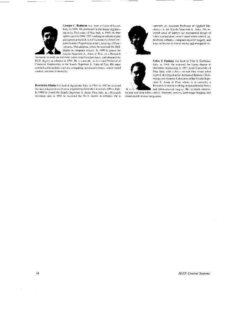
Fig. 9 shows an interesting case in which the object was unexpectedly stopped during its motion. As visible from the curves, at time t = 1.5 s, the prediction module found that the catching condition could not be guaranteed, since (4) was not satisfied. As a consequence, the robot stopped its motion, by switching to a stopping trajectory, until the condition was veri- fied. In Fig. 9, the catching condition was verified at time t = 2.1 s, when the object started moving again. Also in this case, the robot found a trajectory to reach the catching line in time to trap the object. The results of these experiments are also available on a video tape.
Real Working System A methodology for catching a fast moving object by a robot
manipulator has been presented. Visual information from a fixed camera is employed to track the trajectory of the target. The main contribution of this work is the successful design and implemen- tation of a real working system, in which sensing, tracking, motion prediction techniques, planning strategies, and sensor-
54 IEEE Control Systems
I I
Fig. 9. End-effector trajectory while catchin!: an object which stops and restarts.
based control algorithms are performed in real-time, and have been integrated in a modular control architecture. It is notable that all the experiments make use of a single PC 386 at 25 MHz, running under the HAREMS flexible programming environment [lo], designed for developing hierarchical control loops.
The prediction algorithm. integrated with the real-time plan- ning, allows the system to cope with possible unpredictable trajectory changes of the moving target, in spite of the time delays introduced by visual processing and by the robot position con- troller.
A simple but reliable model of the robot position loop has been taken into account in the control algorithm for improving the performance of the system. Due to the fact that no joint measurement is available on line from the robot position controller, the model also has been used for estimating the end-effector position, based on commands history. Although such use of the model is beyond its scope, the good results obtained testify the reliability of the model itself, and confirm the effectiveness of inner-outer loops control schemes in multisensor robot systems. Experimental results have shown that the robot system is capable of tracking and catching an object moving on a plane at velocities of up to 700 mm/s and accelerations of up to 1500 mm/s-.
Future work will concern the implementation of more sophis- ticated vision algorithms to recognize objects in a less structured environment, and will be addressed on the use of stereo vision for extending the approach to the three-dimensional case.
Acknowledgment The authors thank the reviewers for their useful suggestions
to improve the readability of the paper. A special thanks to Mr. G.B. Catalano for the freehand drawing.
References [ I ] E.W. Aboaf, S.M. Drucker, and C.G. Atkeson. “Task-level robot learning: Juggling a tennis ball more accurately,”in Proc. /EEE /lit Conf Robot. Auto., Scottsdale, AZ, May 1989, pp. 1290- 1295.
[2] P. Allen, B. Yoshimi, A. Timchenko, “Real time visual servoing,” infrocc IEEE Int. Conf. Robot. Auto., Apr. 1991, pp. 85 1-8.56.
[3] P. Allen, B. Yoshimi, A. Tiinchenko. and P. Michelman, “Trajectory filtering and prediction for automated tracking and grasping of a moving
object,” in Proc. I€€E Int. Conf Robot. Auto., Nice, France, May 1992. pp. 1850- 1856.
[4] B. Allotta and G. Buttazzo, “Impact handling by proximity and force sensing,” in Proc. IEEE Int. Conf Robot. Auto., Nice, France, May 1992, pp. 2032-2037.
[5] B. Allotta, G. Buttazzo, and F.P. Fanizza, “High-performance hand-eye coordination: The ball and plate problem,” in P roc. Int. Workshop Mecha- tronical Comput. Syst. Perception Action, Halmstad University, Sweden, June 1-3, 1993.
[6] R.L. Andersson, “Aggressive trajectory generator for a robot ping-pong player,” I€€€ Control Syst. Mag., Feb. 1989.
[7] R.L. Andersson. “Dynamic sensing in a ping-pong playing robot,” I € € € Trans. Robot. Auto., vol. 5 , Dec. 1989.
(81 C. Archibald and M. van de Panne, “Tracking and grasping moving objects using reflex behavior,” in I€€€ Proc. Int. Conf. Advanced Robot., Pisa, Italy, pp. 643-648, June 1991.
[9] D.H. Ballard and C. H. Brown, Computer Vision. Englewood Cliffs. NJ: Prentice-Hall, 1982.
[ I O ] G.C. Buttazzo, “HAREMS: Hierarchical architecture for rob. Experi- ments with multiple sensors,” in I€€€ P m,. Fifth Int Conf Advanced Robot. (’91 ICARI, Pisa. Italy, pp. 43-48, June 1991.
[ I I ] G.C. Buttazzo and M. Di Natale: “HARTIK: A hard real-time kemel for programming robot tasks with explicit time constraints and guaranteed execution,” in Proc,. ]€E€ Int. Conf Robot. Auto., Atlanta, GA, May 2-6, 1993, pp. 404-409.
[ 121 G. Buttazzo, B. Allotta, and F, Fanizza, “Mousebuster: A robot system for catching fast moving objects by vision,” in Proc. I€€€ Int. Conf Robot. Auto.. Atlanta. GA, May 2-6, 1993, pp. 932-937.
[I31 P.I. Corke and R. Paul, “Video-rate visual servoing for robots.” in Erperrme,italRobotics I , V. Hayward and 0. Kathib, Eds. Springer Verlag, 1989. pp. 429-451.
[ 141 P.I. Corke and M. Good, “Dynamics effects in high performance visual 5ervoing.” in Proc. I€€€ Inr. Cot$ Robot. Auto., May 1992, pp. 1838-1 843.
[ 151 J.T. Feddema and O.R. Mitchell. “Vision-guided servoing with feature- based trajectory generation,” /€€€ Trans. Robot. Auto., vol. 5 , pp. 691 -700, Oct. 1989.
[ 161 J.T. Feddema, C.S.G. Lee, and 0.R. Mitchell, “Weighted selection of image features for resolved rate visual feedback control,”/€€€ Trans. Robot. A im . . vol. 7, pp. 31-47, Feb. 1991.
[ 171 V. Hayward, L. Daneshmend, and A. Nilakantan, “Model based trajec- tory planning using preview,” Tech. Rep. CIM 88-9, McGill Univ., Montreal, Canada, Mar. 1988.
[ 181 N. Houshangi, “Control of a robotic manipulator to grasp a moving target using vision,” in Pro<,. IEEE Int. Conf Robot. Auto., pp. 604-609, May 1990.
[ 191 R. Kuc and B. Barshan, “Bat-like sonar for guiding mobile robots.”IE€€ Control Syst. Mug., Aug. 1992.
[20] J. Lloyd and V. Hayward, “Real-time trajectory generation using blend functions,” in PI-oc. 1EEEInr. Conj: Robot. Auto., pp, 784-789, Apr. 1991.
1211 N. Papanikolopoulos, T. Kanade, and P. Khosla, “Vision and control techniques for robotic visual tracking,” in PI-O.. IEEE Int. Con& Robot. .41rto., pp. 857-864, Apr. 1991.
[22] A.A. Rizzi and D. E. Koditscheck, “Further progress in robot juggling: The spacial two-juggle,” in P roc. /E€€ In/ . Conf Robot. Auto., Atlanta. GA, May 2-6, 1993, pp. 919.924.
[23] L. Weiss, A. Sanderson, and C. Neumann. “Dynamic sensor-based control of robot with visual feedback,”IEEE Tizns. Robot. Auto., Oct. 1987.
February 1994 55
Giorgio C. Buttazzo wa\ born in Cami di Lecce, Italy, in I960 He graduated in electronic engineer- ing at the University of PM. Italy. in 1985 He then \pent a year in 1986- I987 *orking on robotic tactile perception at the G R A S P Labordtory of the Com- puter Science Department at the Univenity of Penn- sylvdnia, Philadelphia. where he received the M S degree in computer science In 1988 he Joined the Scuola Superiore s Anna ot Piad, as d Resedrch
Assistant to work on real-time robot control architectures, dnd obtained the Ph D degree in robotic5 in 1991 He 15 currentl) ~ i i A\\istant Professor ot Computer Engineering at the Scuola Superiore S Anna ot Pisa Hi\ main resedrch areas include real-time computing. ddvanced robotic\, wnsor-based control. and neural network5
Benedetto Allotta was born in Agrigento, Italy, in 1963. In 1987 he received the laureadegree in mechanical engineering from the University of Pisa, Italy. In 1988 he joined the Scuola Superiore S. Anna. Pisa, Italy, as a Research Assistant. and in 1992 he received the Ph.D. degree in robotics. He is
5 6
currently an Assistant Professor of Applied Me- chanics at teh Scuola Superiore S . Anna. His re- search areas of interest are mechanical design of robot manipulators, sensor-based robot control. ag- ricultural robotics. computer-assisted surgery, and force reflection in virtual reality and teleoperation.
Felice P. Fanidza wds born in Villd s Giovanni, Italy. in 1964. He received the laurea degree in electronic engineering in 1991 at the University of Pisa. Italy, with a the$]\ on real-time visual robot control. developed at the Advanced Robotics Tech- nology and Systems LdbordtOry of the Scuola Supe- riore S Anna of Pisa. where is is currently a Research Assistant working on agricultural robotics and robot-dssi\ted wrgery Hi, research interests
include real-time robot control. ultrdsonic \ensor\. laser-range imaging, and virion-tactile \ensor integration
IREE Control Systems