Embed Size (px)
Citation preview

Drive Technology \ Drive Automation \ System Integration \ Services
MOVIAXIS® Multi-Axis Servo InverterMXR Regenerative Power Module
ManualEdition 10/200816607228 / EN

SEW-EURODRIVE – Driving the world
Manual – MOVIAXIS® MXR Regenerative Power Module 3
Content
1
2
3
4
5
6
7
8
9
10
11
12
13
14
15
16
17
18
19
1 General Information .......................................................................................... 51.1 Other applicable documentation ............................................................... 51.2 Structure of the safety notes ..................................................................... 51.3 Rights to claim under limited warranty ...................................................... 61.4 Exclusion of liability................................................................................... 6
2 Safety Notes ...................................................................................................... 72.1 General ..................................................................................................... 72.2 Target group ............................................................................................. 72.3 Designated use ......................................................................................... 72.4 Shipping, putting into storage ................................................................... 82.5 Installation................................................................................................. 82.6 Electrical connection ................................................................................. 92.7 Safe disconnection.................................................................................... 92.8 Operation .................................................................................................. 9
3 Unit Design ...................................................................................................... 103.1 Important information .............................................................................. 103.2 Nameplates, unit designations................................................................ 103.3 Unit design of the MXR regenerative power module .............................. 123.4 Combinations of MXR regenerative power modules with other units ..... 133.5 Standard accessories ............................................................................. 14
4 Installation ....................................................................................................... 164.1 Mechanical installation............................................................................ 164.2 UL-compliant installation......................................................................... 164.3 Installation/removal of the regenerative power module .......................... 184.4 Electrical installation ............................................................................... 184.5 Wiring diagrams ...................................................................................... 214.6 Terminal assignment............................................................................... 23
5 Startup.............................................................................................................. 265.1 General information ................................................................................ 265.2 Settings on regenerative power module for CAN-based system bus ..... 275.3 Settings on regenerative power module for
EtherCAT-based system bus XSE24A ................................................... 295.4 Settings on regenerative power module for EtherCAT fieldbus interface 305.5 Switch-on sequence of MXR regenerative power module ...................... 315.6 Process data assignment for fieldbus operation ..................................... 335.7 Startup of the MXR using MOVITOOLS® MotionStudio ......................... 365.8 Parameter description............................................................................. 39
6 Operation ......................................................................................................... 436.1 General information ................................................................................ 436.2 Operating displays and errors of the MXR regenerative power module . 44
7 Technical Data................................................................................................. 507.1 Technical data of the MXR regenerative power module ......................... 507.2 Dimension sheet of the MXR.. regenerative power module.................... 547.3 Drilling template of the MXR.. regenerative power module..................... 557.4 Technical data of additional components................................................ 56
4 Manual – MOVIAXIS® MXR Regenerative Power Module
Content
8 Project Planning.............................................................................................. 628.1 General information ................................................................................ 628.2 Components for EMC-compliant installation........................................... 628.3 Line contactor and line fuses .................................................................. 638.4 Projecting the power supply.................................................................... 638.5 Projecting the cable cross sections......................................................... 648.6 Selecting the 24 V power supply............................................................. 658.7 Projecting the emergency braking resistor.............................................. 678.8 Dimensioning the MXR regenerative power module............................... 728.9 Output in case of a lower line voltage ..................................................... 728.10 Overload capacity ................................................................................... 738.11 Integrating a regenerative power module in a unit network .................... 748.12 Power supply .......................................................................................... 75
9 Index................................................................................................................. 76
Manual – MOVIAXIS® MXR Regenerative Power Module 5
1 Other applicable documentationGeneral Information
MOVIAXIS® Regenerative Power Module MXR1 General Information1.1 Other applicable documentation
This manual describes the special properties of the MXR regenerative power module For all other information and functionalities of MOVIAXIS®, refer to the followingdocuments:• "MOVIAXIS® Multi-Axis Servo Inverter" operating instructions• "MOVIAXIS® Multi-Axis Servo Inverter" project planning manual
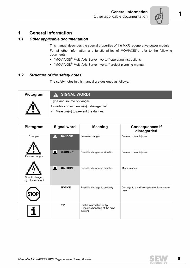
1.2 Structure of the safety notesThe safety notes in this manual are designed as follows:
Pictogram SIGNAL WORD!Type and source of danger.Possible consequence(s) if disregarded.• Measure(s) to prevent the danger.
Pictogram Signal word Meaning Consequences if disregarded
Example:
General danger
Specific danger,e.g. electric shock
DANGER! Imminent danger Severe or fatal injuries
WARNING! Possible dangerous situation Severe or fatal injuries
CAUTION! Possible dangerous situation Minor injuries
NOTICE Possible damage to property Damage to the drive system or its environ-ment
TIP Useful information or tipSimplifies handling of the drive system.
6 Manual – MOVIAXIS® MXR Regenerative Power Module
1 Rights to claim under limited warranty General Information
1.3 Rights to claim under limited warrantyA requirement of fault-free operation and fulfillment of any rights to claim under limit-ed warranty is that you adhere to the information in this manual and the "MOVIAXIS®
Multi-Axis Servo Inverter" operating instructions. Read the operating instructionsbefore you start operating the unit!Make sure that the operating instructions are available to persons responsible for thesystem and its operation as well as to persons who work independently on the unit. Youmust also ensure that the documentation is legible.
1.4 Exclusion of liabilityYou must comply with the information contained in the manual at hand and in the"MOVIAXIS® Multi-Axis Servo Inverter" operating instructions to ensure safe op-eration of the MXR regenerative power module in conjunction with the MOVIAXIS®
multi-axis servo inverter and to achieve the specified product characteristics andperformance requirements. SEW-EURODRIVE assumes no liability for injury topersons or damage to equipment or property resulting from non-observance ofthe operating instructions. In such cases, any liability for defects is excluded.
Manual – MOVIAXIS® MXR Regenerative Power Module 7
2 GeneralSafety Notes
2 Safety NotesThe following basic safety notes must be read carefully to prevent injury to persons anddamage to property. The operator must make sure that the basic safety notes are readand observed. Make sure that persons responsible for the plant and its operation, aswell as persons who work independently on the unit, have read through the operatinginstructions carefully and understood them. If you are unclear about any of the informa-tion in this documentation, or if you require further information, please contact SEW-EURODRIVE.
2.1 GeneralNever install damaged products and put them into operation. Submit a complaint to theshipping company immediately in the event of damage.During operation, multi-axis servo inverters can have live, bare and movable or rotatingparts as well as hot surfaces, depending on their enclosure.Removing covers without authorization, improper use as well as incorrect installation oroperation may result in severe injuries to persons or damage to property.Consult the documentation for further information.
2.2 Target groupOnly qualified personnel are authorized to install, startup or service the units or correctunit faults (observing IEC 60364 or CENELEC HD 384 or DIN VDE 0100 and IEC 60664or DIN VDE 0110 as well as national accident prevention guidelines).Qualified personnel in the context of these basic safety notes are persons familiar withinstallation, assembly, startup and operation of the product who possess the necessaryqualifications.All activity in the other areas of transportation, storage, operation, and disposal must becarried out by persons who are appropriately trained.
2.3 Designated useThe MXR regenerative power module is designed for integration in the unit network ofthe MOVIAXIS® MX multi-axis servo inverter.The MOVIAXIS® MX multi-axis servo drives are units for use in industrial and commer-cial systems to operate permanent-field synchronous AC motors and asynchronous ACmotors with encoder feedback. These motors must be suitable for operation with servoinverters. Connect other loads to the units only after you have consulted the manufac-turer.
TIPObserve the information about the other modules of a MOVIAXIS® axis system in the"MOVIAXIS® MX Multi-Axis Servo Inverter" operating instructions when installing,starting up, and operating the MXR regenerative power module.

8 Manual – MOVIAXIS® MXR Regenerative Power Module
2 Shipping, putting into storage Safety Notes
The MOVIAXIS® MX multi-axis servo drives are intended for use in metal control cabi-nets. These metal control cabinets represent the necessary enclosure for the applicationas well as the grounding over a large area required for EMC purposes.For installation in machines, startup of the multi-axis servo inverter (meaning the start ofdesignated use) is prohibited until it is determined that the machine meets the require-ments stipulated in the EC Directive 98/37/EC (machine directive); observe EN 60204.Startup (i.e. start of designated operation) is only permitted with adherence to the EMCguideline (89/336/EEC).The multi-axis servo inverters meet the requirements stipulated in the low voltage guide-line 200695EC. The harmonized standards of the EN 61800-5-1 DIN VDE/T105 seriesin connection with EN 60439-1 VDE 0660 part 500 and EN 60146 VDE/0558 are appliedto the multi-axis servo inverters.Technical data and information on the connection requirements are given on the name-plate and in the documentation; they must be observed under all circumstances.
2.3.1 Safety functionsMOVIAXIS® multi-axis servo inverters may not take on safety functions without a higher-level safety system. Use higher-level safety systems to ensure protection of equipmentand personnel.For safety applications, refer to the information in the following publications:• Safe Disconnection for MOVIAXIS® – Conditions.• Safe Disconnection for MOVIAXIS® – Applications.
2.4 Shipping, putting into storageObserve the notes on transportation, storage and proper handling. Observe the climaticconditions as stated in the "MOVIAXIS® Multi-Axis Servo Inverter" operating instructionsin the "General technical data" chapter.
2.5 InstallationThe units must be installed and cooled according to the regulations and specificationsin the corresponding documentation.Protect the multi-axis servo inverters from excessive strain. Especially during transpor-tation and handling, do not allow the components to be deformed and/or insulation spac-es altered. Avoid contact with electronic components and contacts.Multi-axis servo inverters contain components that can be damaged by electrostatic en-ergy and could be destroyed in case of improper handling. Prevent mechanical damageor destruction of electric components (may pose health risk).
Manual – MOVIAXIS® MXR Regenerative Power Module 9
2 Electrical connectionSafety Notes
The following applications are prohibited unless the unit is explicitly designed for suchuse:• Use in potentially explosive areas.• Use in areas exposed to harmful oils, acids, gases, vapors, dust, radiation, etc.• Use in non-stationary applications that are subject to mechanical vibration and shock
loads in excess of the requirements in EN 61800-5-1.
2.6 Electrical connectionObserve the applicable national accident prevention guidelines when working on livemulti-axis servo inverters (for example, BGV A3).Perform electrical installation according to the pertinent regulations (e.g. cable crosssections, fusing, protective conductor connection). Additional information is contained inthe documentation.You will find notes on EMC-compliant installation, such as shielding, grounding, ar-rangement of filters and routing of lines, in the documentation of the multi-axis servo in-verters. Always observe these notes even with multi-axis servo inverters bearing the CEmarking. The manufacturer of the system or machine is responsible for maintaining thelimits established by EMC legislation.Preventive measures and protection devices must correspond to the regulations in force(e.g. EN 60204 or EN 61800-5-1).Required preventive measures: Grounding the unit.
2.7 Safe disconnectionMOVIAXIS® meets all requirements for safe disconnection of power and electronic con-nections in accordance with EN 61800-5-1. All connected circuits must also satisfy therequirements for safe disconnection.
2.8 OperationSystems with multi-axis servo inverters must be equipped with additional monitoring andprotection devices, as applicable, according to the relevant safety guidelines and regu-lations, such as legislation governing technical equipment, accident prevention regula-tions, etc. Changes to the multi-axis servo inverter using the software are permitted.Do not touch live components or power connections immediately after disconnecting themulti-axis servo inverters from the supply voltage because there may still be somecharged capacitors. Note the respective labels on the multi-axis servo inverter.Keep all covers and doors closed during operation.The fact that the status LED and other display elements are no longer illuminated doesnot indicate that the unit has been disconnected from the supply system and no longercarries any voltage.Mechanical blocking or internal safety functions of the unit can cause a motor standstill.Eliminating the cause of the problem or performing a reset may result in the drive re-starting automatically. If, for safety reasons, this is not permitted for the driven machine,disconnect the unit from the supply system before correcting the fault.
10 Manual – MOVIAXIS® MXR Regenerative Power Module
3 Important information Unit Design
3 Unit Design3.1 Important information
Protective measures and protective equipment have to meet the respective nationalregulations in effect.
3.2 Nameplates, unit designations3.2.1 Nameplate of MXR regenerative power module
TIPFollow the specific operating instructions during installation and startup of the motorand the brake!
WARNING!The following "Unit design" illustrations represent the units without the provided protec-tion cover (touch guard). The protection cover protects the area of the line and brakingresistor connections.Uncovered power connections.Severe or fatal injuries from electric shock.• Install the touch guard according to the regulations.• Never start the unit if the touch guard is not installed.
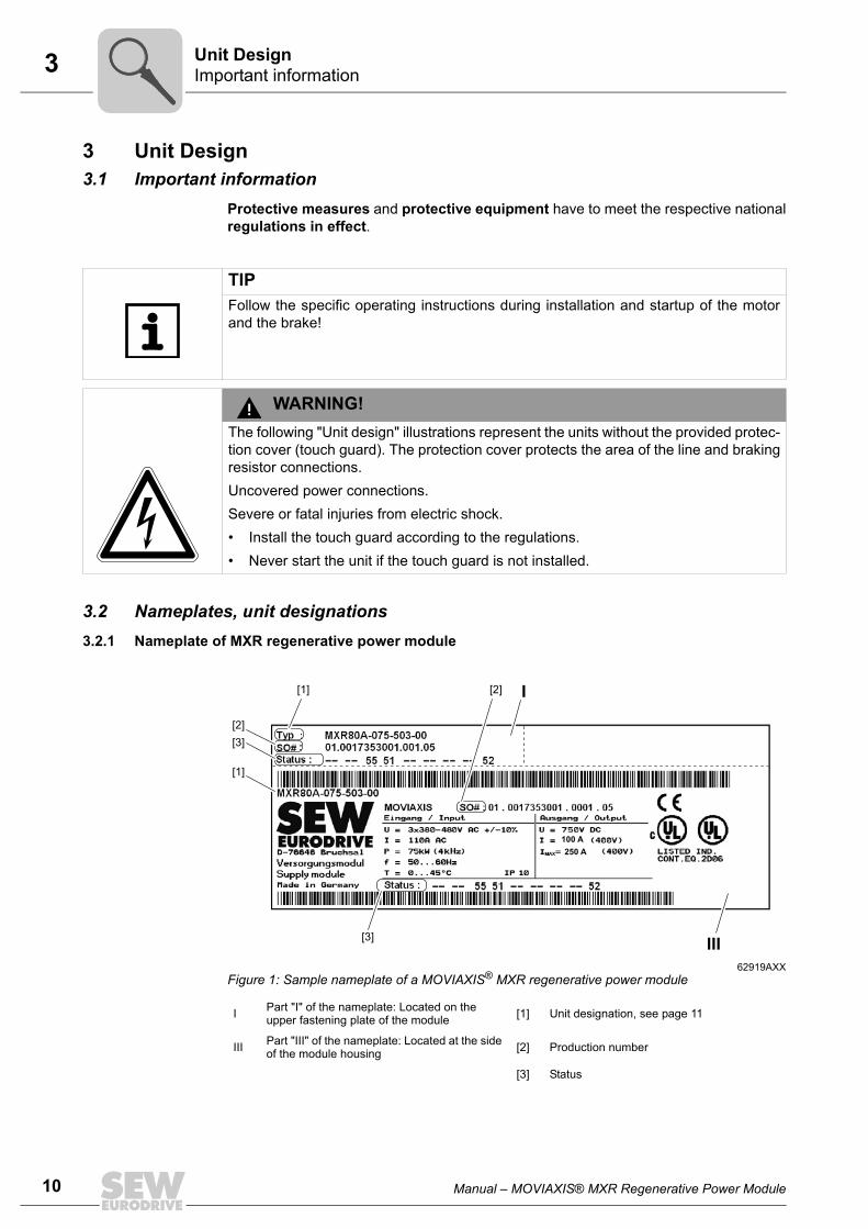
62919AXXFigure 1: Sample nameplate of a MOVIAXIS® MXR regenerative power module
I Part "I" of the nameplate: Located on the upper fastening plate of the module [1] Unit designation, see page 11
III Part "III" of the nameplate: Located at the side of the module housing [2] Production number
[3] Status
I[2][1]
[2]
[1]
[3]
III[3]
100 A
250 A
Manual – MOVIAXIS® MXR Regenerative Power Module 11
3 Nameplates, unit designationsUnit Design
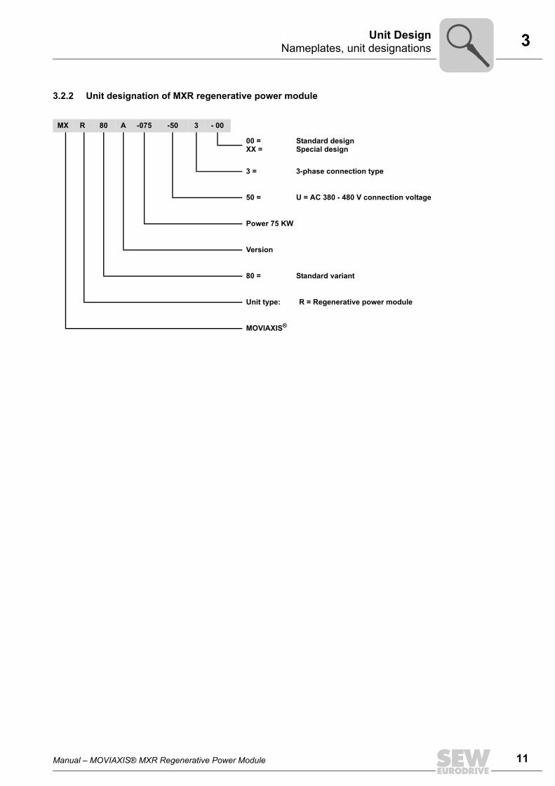
3.2.2 Unit designation of MXR regenerative power module
MX R 80 A -075 -50 3 - 00
00 =XX =
Standard designSpecial design
3 = 3-phase connection type
50 = U = AC 380 - 480 V connection voltage
Power 75 KW
Version
80 = Standard variant
Unit type: R = Regenerative power module
MOVIAXIS®
12 Manual – MOVIAXIS® MXR Regenerative Power Module
3 Unit design of the MXR regenerative power module Unit Design
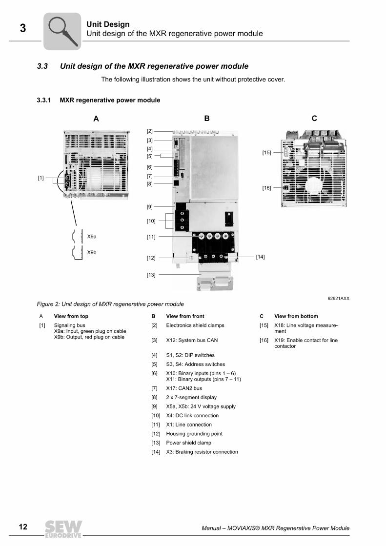
3.3 Unit design of the MXR regenerative power moduleThe following illustration shows the unit without protective cover.
3.3.1 MXR regenerative power module
62921AXXFigure 2: Unit design of MXR regenerative power module
A View from top B View from front C View from bottom
[1] Signaling busX9a: Input, green plug on cableX9b: Output, red plug on cable
[2] Electronics shield clamps [15] X18: Line voltage measure-ment
[3] X12: System bus CAN [16] X19: Enable contact for line contactor
[4] S1, S2: DIP switches
[5] S3, S4: Address switches
[6] X10: Binary inputs (pins 1 – 6)X11: Binary outputs (pins 7 – 11)
[7] X17: CAN2 bus
[8] 2 x 7-segment display
[9] X5a, X5b: 24 V voltage supply
[10] X4: DC link connection
[11] X1: Line connection
[12] Housing grounding point
[13] Power shield clamp
[14] X3: Braking resistor connection
X9a
X9b
BA
[1]
[4]
[10]
[3]
[15]
[16]
C
[2]
[5]
[6]
[8]
[7]
[9]
[11]
[13]
[12] [14]
Manual – MOVIAXIS® MXR Regenerative Power Module 13
3 Combinations of MXR regenerative power modules with other unitsUnit Design
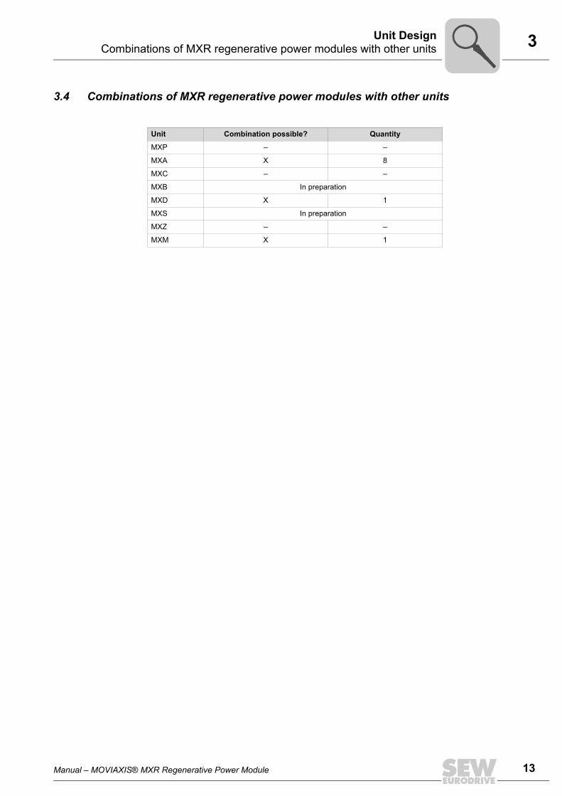
3.4 Combinations of MXR regenerative power modules with other units
Unit Combination possible? Quantity
MXP – –
MXA X 8
MXC – –
MXB In preparation
MXD X 1
MXS In preparation
MXZ – –
MXM X 1
14 Manual – MOVIAXIS® MXR Regenerative Power Module
3 Standard accessories Unit Design
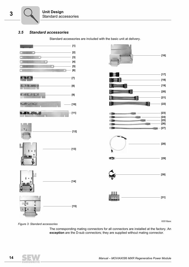
3.5 Standard accessoriesStandard accessories are included with the basic unit at delivery.
The corresponding mating connectors for all connectors are installed at the factory. Anexception are the D-sub connectors; they are supplied without mating connector.
63518axxFigure 3: Standard accessories
[1]
[2]
[3]
[4]
[5]
[6]
[7]
[8]
[9]
[10]
[12]
[15]
[30]
[16]
[11]
[18]
[19]
[20]
[21]
[22]
[24]
[25]
[26]
[27]
[17]
[23]
[29]
[28]
[13]
[14]
[31]
Manual – MOVIAXIS® MXR Regenerative Power Module 15
3 Standard accessoriesUnit Design
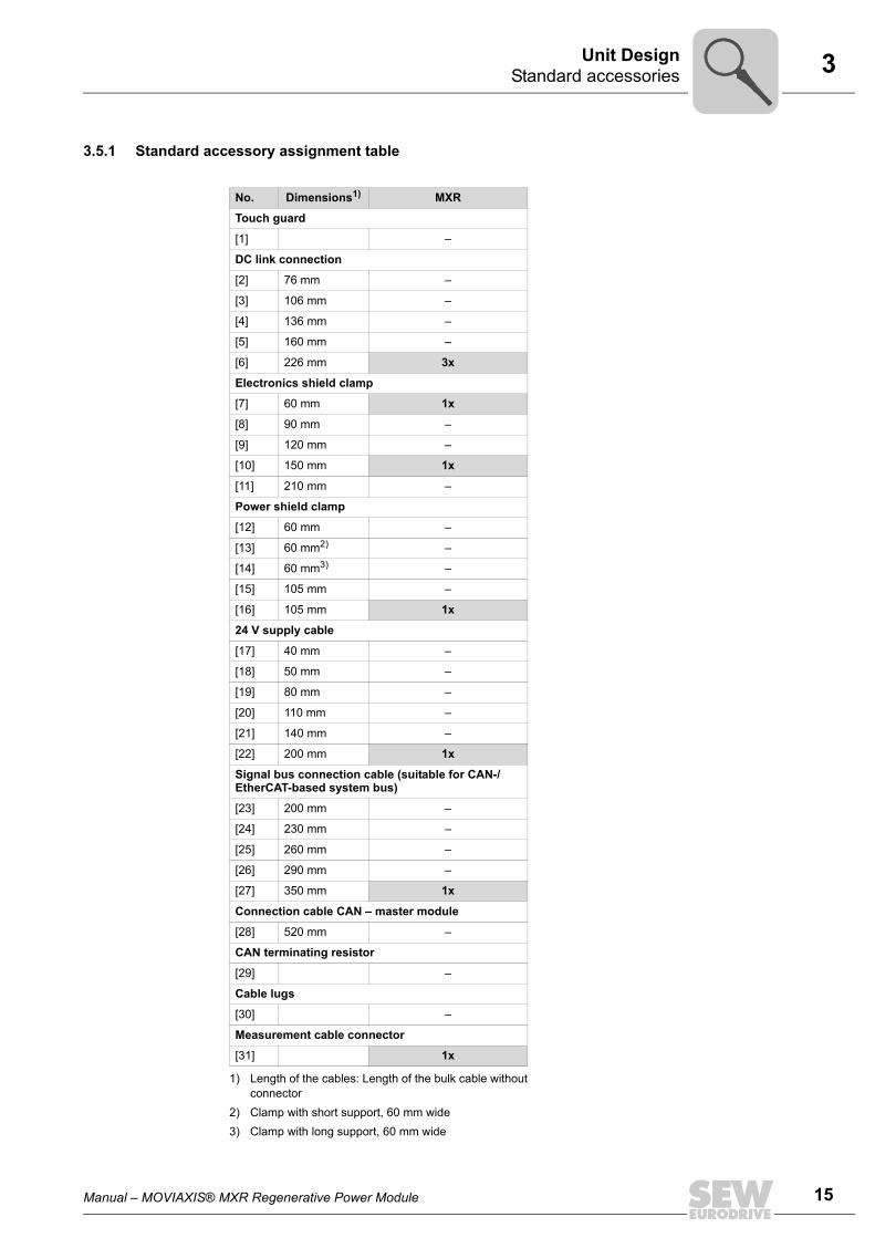
3.5.1 Standard accessory assignment table
No. Dimensions1)
1) Length of the cables: Length of the bulk cable withoutconnector
MXR
Touch guard
[1] –
DC link connection
[2] 76 mm –
[3] 106 mm –
[4] 136 mm –
[5] 160 mm –
[6] 226 mm 3x
Electronics shield clamp
[7] 60 mm 1x
[8] 90 mm –
[9] 120 mm –
[10] 150 mm 1x
[11] 210 mm –
Power shield clamp
[12] 60 mm –
[13] 60 mm2)
2) Clamp with short support, 60 mm wide
–
[14] 60 mm3)
3) Clamp with long support, 60 mm wide
–
[15] 105 mm –
[16] 105 mm 1x
24 V supply cable
[17] 40 mm –
[18] 50 mm –
[19] 80 mm –
[20] 110 mm –
[21] 140 mm –
[22] 200 mm 1x
Signal bus connection cable (suitable for CAN-/ EtherCAT-based system bus)
[23] 200 mm –
[24] 230 mm –
[25] 260 mm –
[26] 290 mm –
[27] 350 mm 1x
Connection cable CAN – master module
[28] 520 mm –
CAN terminating resistor
[29] –
Cable lugs
[30] –
Measurement cable connector
[31] 1x
16 Manual – MOVIAXIS® MXR Regenerative Power Module
4 Mechanical installation Installation
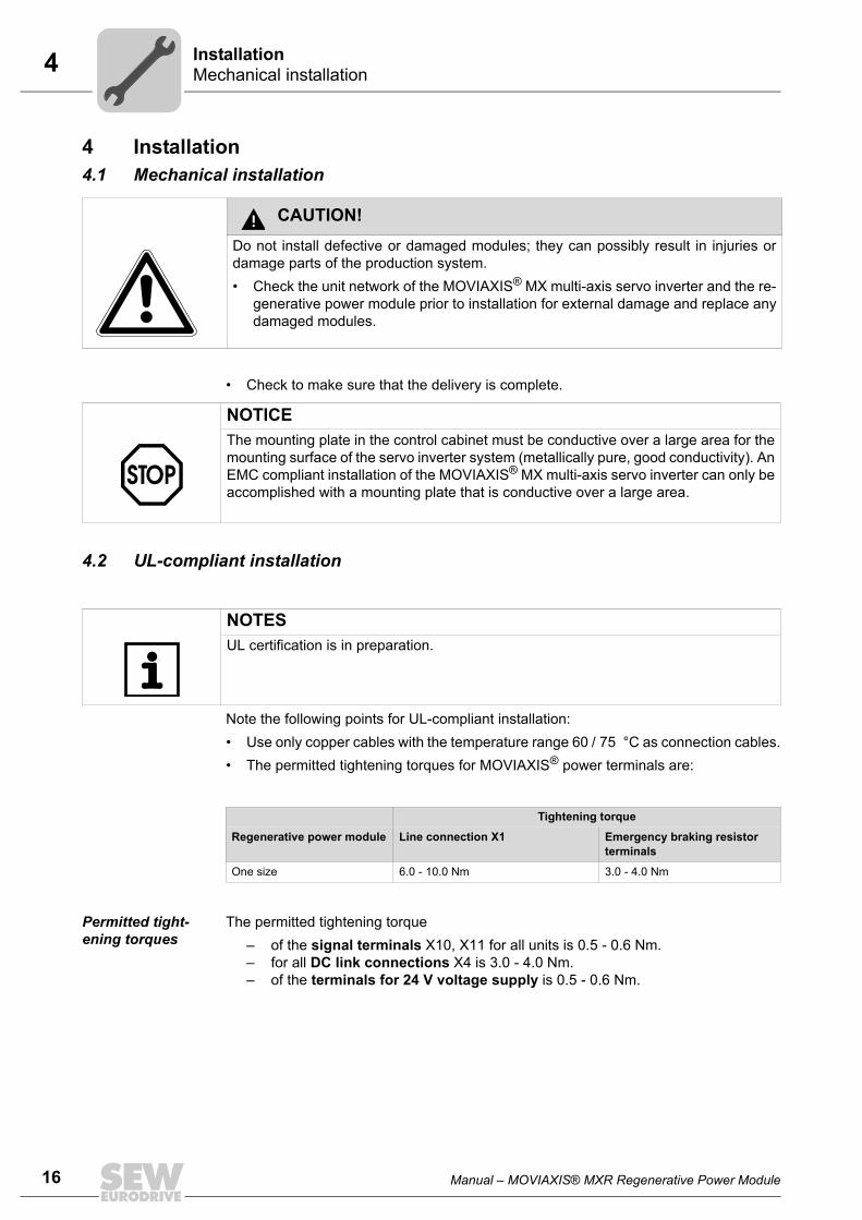
4 Installation4.1 Mechanical installation
• Check to make sure that the delivery is complete.
4.2 UL-compliant installation
Note the following points for UL-compliant installation:• Use only copper cables with the temperature range 60 / 75 °C as connection cables.• The permitted tightening torques for MOVIAXIS® power terminals are:
Permitted tight-ening torques
The permitted tightening torque – of the signal terminals X10, X11 for all units is 0.5 - 0.6 Nm.– for all DC link connections X4 is 3.0 - 4.0 Nm.– of the terminals for 24 V voltage supply is 0.5 - 0.6 Nm.
CAUTION!Do not install defective or damaged modules; they can possibly result in injuries ordamage parts of the production system.• Check the unit network of the MOVIAXIS® MX multi-axis servo inverter and the re-
generative power module prior to installation for external damage and replace anydamaged modules.
NOTICEThe mounting plate in the control cabinet must be conductive over a large area for themounting surface of the servo inverter system (metallically pure, good conductivity). AnEMC compliant installation of the MOVIAXIS® MX multi-axis servo inverter can only beaccomplished with a mounting plate that is conductive over a large area.
NOTESUL certification is in preparation.
Tightening torque
Regenerative power module Line connection X1 Emergency braking resistor terminals
One size 6.0 - 10.0 Nm 3.0 - 4.0 Nm

Manual – MOVIAXIS® MXR Regenerative Power Module 17
4 UL-compliant installationInstallation
• MOVIAXIS® MX multi-axis servo inverters are suitable for operation in voltage net-works with earthed star point (TN and TT networks), a maximum line current of42,000 A and a maximum line voltage of AC 480 V.
• The maximum permitted value of the line fuse is:
• Only use melting fuses as input fuses.• If you use cable cross sections that are dimensioned for a smaller current than the
rated current of the unit, make sure that the fuse is dimensioned for the used cablecross section.
• For information on selecting cable cross sections, refer to the project planning man-ual.
• Comply with the country-specific installation regulations in addition to the abovenotes.
• The plug-in connections of the 24 V supply are limited to 10 A.
NOTICERegenerative power module can possibly be damaged!.• Only use the stipulated connection elements and observe the prescribed tightening
torques. Otherwise, excessive heat can develop which would damage the regener-ative power module.
MXR regenerative power module "Maximum Power" variant "Clean Power" variant
PN 75 kW 50 kW
IN 110 A 73 A
Input fuse 125 A 80 A
NOTICEWe recommend protection of the emergency braking resistor with a thermal overloadrelay to implement an UL approved application design.
NOTESObserve the technical data for operation of the required line filters (page 56) and linechokes (page 59).The cross section of the measuring cable X18 of the line filter must be AWG12, seewiring diagram on page 22.
18 Manual – MOVIAXIS® MXR Regenerative Power Module
4 Installation/removal of the regenerative power module Installation
4.3 Installation/removal of the regenerative power moduleRefer to the "MOVIAXIS® MX Multi-Axis Servo Inverter" operation instructions for a de-scription how to install a module in an axis system and how to remove it. Adhere to theinstructions for installing/removing a module.
4.4 Electrical installationThis chapter specifically describes the electrical installation of the MXR regenerativepower module. For detailed information on the electrical installation of the MOVIAXIS® axis system, re-fer to the "MOVIAXIS® MX Multi-Axis Servo Inverter" operating instructions.
DANGER!Dangerous voltage levels may still be present inside the unit and at the terminal stripsup to 10 minutes after the complete axis system has been disconnected from the sup-ply system.Severe or fatal injuries from electric shock.To prevent electric shocks:• Disconnect the axis system from the supply system and wait ten minutes before re-
moving the protective covers.• Secure the motor against unintended power-up.• After maintenance work, do not operate the axis system unless you have replaced
the protective cover because the unit only has degree of protection IP00 withoutprotective cover.
DANGER!A leakage current > 3.5 mA can occur during operation of the MOVIAXIS® MX multi-axis servo inverter.Severe or fatal injuries from electric shock.To prevent electric shock:• With a supply system lead < 10 mm2, route a second PE conductor with the same
cross section as the supply system lead via separate terminals. Alternatively, youcan use a PE conductor with a copper cross section ≥10 mm2 or aluminum≥16 mm2.
• With an incoming supply line ≥10 mm2, it is sufficient to install a PE conductor witha copper cross section ≥10 mm2 or aluminum ≥10 mm2.
• If an earth leakage circuit breaker can be used for protection against direct and in-direct contact, it must be universal current sensitive (RCD type B).
Manual – MOVIAXIS® MXR Regenerative Power Module 19
4 Electrical installationInstallation
4.4.1 Line contactor and cable cross sections
• Supply cable: Cross section according to rated input current Iline at rated load.
4.4.2 Measuring cable X18 of the line filterFor the measuring cable X18, we recommend a cross section of 2.5 mm2. The requirements for UL-compliant installation of the measuring cable X18 are listed onpage 16 ff.The measuring cable may only be fused up to 120 A.
4.4.3 Emergency braking resistor connection
• Protect the emergency braking resistor with an overload relay. Set the trip currentaccording to the technical data of the emergency braking resistor, see"MOVIAXIS® MX Multi-Axis Servo Inverter" operating instructions.
• SEW-EURODRIVE recommends to connect the emergency braking resistor asshown in the "MOVIAXIS® MX Multi-Axis Servo Inverter" operating instructions. In-stall switch F16 close to the unit network. If an unshielded cable is used for connect-ing switch F16 with the regenerative power module, keep the length as short as pos-sible. Preferably use a shielded line cable or drilled individual lines as connection ca-ble to the emergency braking resistor. The cross section must be selected dependingon the rated current of the emergency braking resistor.
TIPInstallation with reliable isolation.The unit meets all requirements for reliable isolation between power and electronicconnections according to EN 61800-5-1. The connected signal circuits have to meetthe requirements according to SELV (Safe Extremly Low Voltage) or PELV (ProtectiveExtra Low Voltage) to ensure reliable isolation. The installation must meet the require-ments for reliable isolation.
NOTICE• Use a line contactor in utilization category AC-3 (IEC 158-1) or better. For infor-
mation on the current carrying capacity, refer to chapter "MXR regenerativepower module" (page 52).
NOTICEObserve the notes in chapter "Project planning" (page 62) when using an emergencybraking resistor.
20 Manual – MOVIAXIS® MXR Regenerative Power Module
4 Electrical installation Installation
4.4.4 Operation of the emergency braking resistor
• The connection lead to the emergency braking resistor carries a high DC voltage ofabout 970 V during rated operation.
4.4.5 Permitted voltage supply systems• MOVIAXIS® is intended for operation on voltage supply systems with a directly
grounded star point (TN and TT power systems). • Operation on voltage supply systems with a non-grounded star point (for example IT
power systems) is not permitted.• Autonomous power systems are not permitted.
An autonomous power system has no connection to the public grid.
WARNING!The surfaces of the emergency braking resistor will reach temperatures of up to 250°Cwhen the braking resistor is loaded with PN.Risk of burns and fire.• Choose a suitable installation location. Emergency braking resistors are usually
mounted on top of the control cabinet.• Do not touch any emergency braking resistor.
Manual – MOVIAXIS® MXR Regenerative Power Module 21
4 Wiring diagramsInstallation
4.5 Wiring diagrams4.5.1 General notes on the wiring diagrams
• All units within the axis group will have to be connected to each other via the DC linkbus connection (PE, +Uz, –Uz), the 24 V bus (X5a, X5b) and the signaling bus (X9a,X9b).
• The line contactor "K11" must be installed between the supply system and the linefilter.
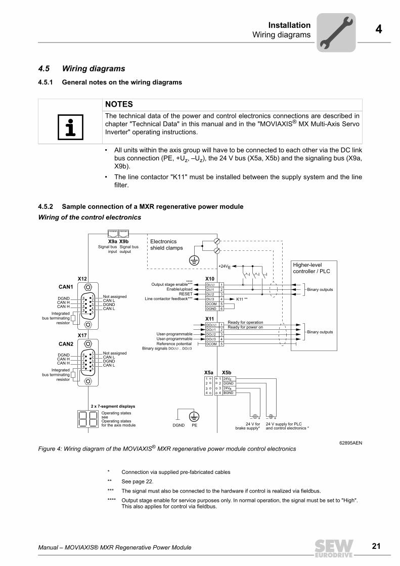
4.5.2 Sample connection of a MXR regenerative power moduleWiring of the control electronics
NOTESThe technical data of the power and control electronics connections are described inchapter "Technical Data" in this manual and in the "MOVIAXIS® MX Multi-Axis ServoInverter" operating instructions.
62895AENFigure 4: Wiring diagram of the MOVIAXIS® MXR regenerative power module control electronics
X9a X9b
X10X12
X17
Signal businput
Signal busoutput
16
7
8
9
2
3
4
5
Not assignedCAN LDGNDCAN L
DGNDCAN HCAN H
Integratedbus terminating
resistor
16
7
8
9
2
3
4
5
Not assignedCAN LDGNDCAN L
DGNDCAN HCAN H
Integratedbus terminating
resistor
Electronics
shield clamps
Higher-level
controller / PLC
1
2
3
4
DCOM 5
DGND 6
Output stage enable***
+24VE
Enable/upload
RESET
Line contactor feedback***
Ready for operation
Ready for power on
K11 **
X111
2
3
4
DCOM 5
User-programmable
User-programmable
Binary outputs
Binary outputs
2 x 7-segment displays
Operating statesseeOperating states for the axis module
2
X5bX5a1 24VE
DGND
3 24VB
4
2
1
3
4 BGND
PEDGND
+–+–
24 V forbrake supply*
24 V supply for PLCand control electronics *
-^-I -^-I --I
****
CAN1
CAN2 Reference potentialBinary signals
* Connection via supplied pre-fabricated cables
** See page 22.
*** The signal must also be connected to the hardware if control is realized via fieldbus.
**** Output stage enable for service purposes only. In normal operation, the signal must be set to "High". This also applies for control via fieldbus.
22 Manual – MOVIAXIS® MXR Regenerative Power Module
4 Wiring diagrams Installation
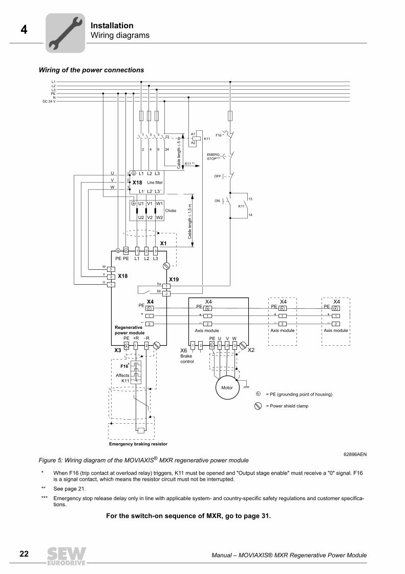
Wiring of the power connections
For the switch-on sequence of MXR, go to page 31.
62896AENFigure 5: Wiring diagram of the MOVIAXIS® MXR regenerative power module
* When F16 (trip contact at overload relay) triggers, K11 must be opened and "Output stage enable" must receive a "0" signal. F16 is a signal contact, which means the resistor circuit must not be interrupted.
** See page 21.
*** Emergency stop release delay only in line with applicable system- and country-specific safety regulations and customer specifica-tions.
L1 L2 L3
L1´ L2´ L3´
Line filter
L1
ON
L2L3PE
NDC 24 V
X1
1 2 3
L1 L2 L3PE
X4
–
+
PE
Sa
Sb
X18X19
1
2Regenerative
power module
X3
–R+RPE
1 2
Emergency braking resistor
Affects
K11
X4
–
+
PE
Axis module
X2X6
Motor
1 2 321
Brake
control
PE U V W
X4
–
+
PE
Axis module
–
+
PE
Axis module
F16*
1
2
1
2
1
2
X4
Ca
ble
len
gth
≤ 1
,5 m
PE
= PE (grounding point of housing)
= Power shield clamp
EMERG.
STOP***
K11
14
13
1
2
3
4
5
6
23
24
A1
A2K11
K11 **
OFF
F16 *
U
V
W
U1 V1 W1
U2 V2 W2
Choke
1
2
3
2
1
W
V
U
X18
1
2
3
Ca
ble
len
gth
≤ 5
m
Manual – MOVIAXIS® MXR Regenerative Power Module 23
4 Terminal assignmentInstallation
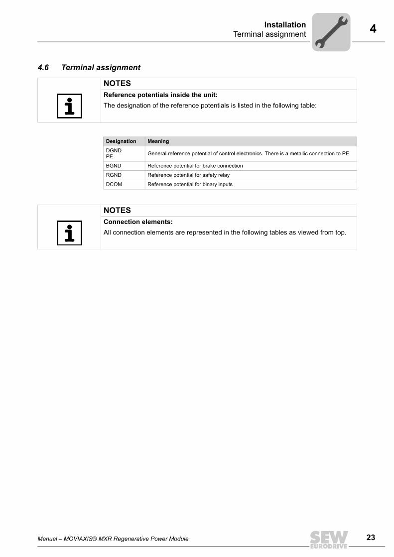
4.6 Terminal assignment
NOTESReference potentials inside the unit:The designation of the reference potentials is listed in the following table:
Designation Meaning
DGNDPE General reference potential of control electronics. There is a metallic connection to PE.
BGND Reference potential for brake connection
RGND Reference potential for safety relay
DCOM Reference potential for binary inputs
NOTESConnection elements:All connection elements are represented in the following tables as viewed from top.
24 Manual – MOVIAXIS® MXR Regenerative Power Module
4 Terminal assignment Installation
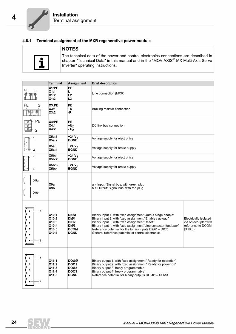
4.6.1 Terminal assignment of the MXR regenerative power module
NOTESThe technical data of the power and control electronics connections are described inchapter "Technical Data" in this manual and in the "MOVIAXIS® MX Multi-Axis ServoInverter" operating instructions.
Terminal Assignment Brief descriptionX1:PEX1:1X1:2X1:3
PEL1L2L3
Line connection (MXR)
X3:PEX3:1X3:2
PE+R-R
Braking resistor connection
X4:PEX4:1X4:2
PE+UZ- UZ
DC link bus connection
X5a:1X5a:2
+24 VEDGND Voltage supply for electronics
X5a:3X5a:4
+24 VBBGND Voltage supply for brake supply
X5b:1X5b:2
+24 VEDGND Voltage supply for electronics
X5b:3X5b:4
+24 VBBGND Voltage supply for brake supply
X9aX9b
a = Input: Signal bus, with green plugb = Output: Signal bus, with red plug
X10:1X10:2X10:3X10:4X10:5X10:6
DIØØDIØ1DIØ2DIØ3DCOMDGND
Binary input 1, with fixed assignment"Output stage enable"Binary input 2, with fixed assignment "Enable / upload"Binary input 3, with fixed assignment"Reset"Binary input 4, with fixed assignment"Line contactor feedback"Reference potential for the binary inputs DIØØ – DIØ3General reference potential of control electronics
Electrically isolated via optocoupler with reference to DCOM (X10:5).
X11:1X11:2X11:3X11:4X11:5
DOØØDOØ1DOØ2DOØ3DGND
Binary output 1, with fixed assignment "Ready for operation"Binary output 2, with fixed assignment "Ready for power on"Binary output 3, freely programmableBinary output 4, freely programmableReference potential for binary outputs DOØØ – DOØ3
PE 3
PE 2
PE
2
1
4
1
4
X9a
X9b
1
6
1
5
Manual – MOVIAXIS® MXR Regenerative Power Module 25
4 Terminal assignmentInstallation
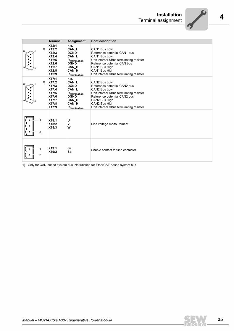
1)X12:1X12:2X12:3X12:4X12:5X12:6X12:7X12:8X12:9
n.c.CAN_LDGNDCAN_LRterminationDGNDCAN_HCAN_HRtermination
–CAN1 Bus LowReference potential CAN1 busCAN1 Bus LowUnit internal SBus terminating resistorReference potential CAN busCAN1 Bus HighCAN1 Bus HighUnit internal SBus terminating resistor
1)X17:1X17:2X17:3X17:4X17:5X17:6X17:7X17:8X17:9
n.c.CAN_LDGNDCAN_LRterminationDGNDCAN_HCAN_HRtermination
–CAN2 Bus LowReference potential CAN2 busCAN2 Bus LowUnit internal SBus terminating resistorReference potential CAN2 busCAN2 Bus HighCAN2 Bus HighUnit internal SBus terminating resistor
X18:1X18:2X18:3
UVW
Line voltage measurement
X19:1X19:2
SaSb Enable contact for line contactor
1) Only for CAN-based system bus. No function for EtherCAT-based system bus.
Terminal Assignment Brief description
6
9 5
1
6
9 5
1
1
3
1
2
26 Manual – MOVIAXIS® MXR Regenerative Power Module
5 General information Startup
5 StartupThis chapter specifically describes the startup of the MXR regenerative power module. For detailed information on the startup of the MOVIAXIS® axis system, refer to the"MOVIAXIS® MX Multi-Axis Servo Inverter" operating instructions.
5.1 General information
Prerequisite The drive must be configured correctly to ensure that startup is successful. Refer to the"MOVIAXIS® MX Multi-Axis Servo Inverter" project planning manual for detailed projectplanning notes and an explanation of the parameters.For starting up the entire axis system, observe chapter "Startup" in the "MOVIAXIS® MXMulti-Axis Servo Inverter" operating instructions.
DANGER!Uncovered power connections.Severe or fatal injuries from electric shock.• Install the touch guard according to the regulations.• Never start the unit if the touch guard is not installed.
NOTESIn addition to the requirements specified in the operating instructions and the projectplanning manual for MOVIAXIS® MX, the MXA8... axis modules must be equipped withfirmware .24 or higher.
00
I
Manual – MOVIAXIS® MXR Regenerative Power Module 27
5 Settings on regenerative power module for CAN-based system busStartup
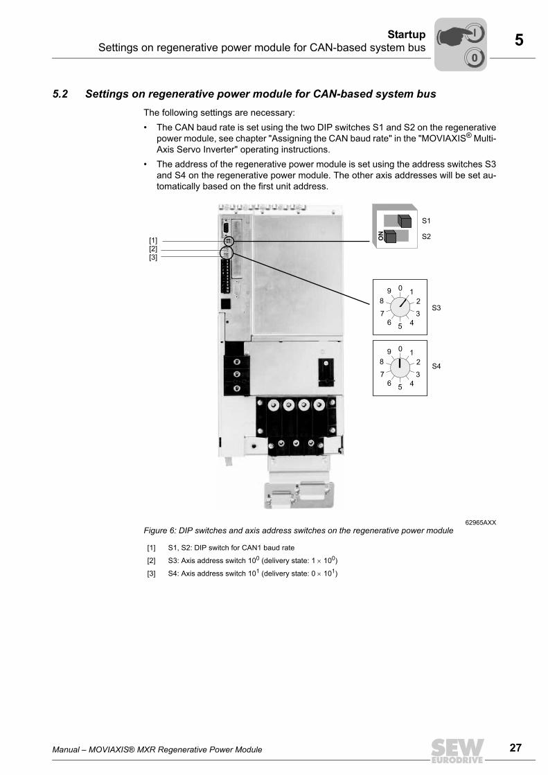
5.2 Settings on regenerative power module for CAN-based system busThe following settings are necessary:• The CAN baud rate is set using the two DIP switches S1 and S2 on the regenerative
power module, see chapter "Assigning the CAN baud rate" in the "MOVIAXIS® Multi-Axis Servo Inverter" operating instructions.
• The address of the regenerative power module is set using the address switches S3and S4 on the regenerative power module. The other axis addresses will be set au-tomatically based on the first unit address.
62965AXXFigure 6: DIP switches and axis address switches on the regenerative power module
[1] S1, S2: DIP switch for CAN1 baud rate
[2] S3: Axis address switch 100 (delivery state: 1 × 100)
[3] S4: Axis address switch 101 (delivery state: 0 × 101)
[2][3]
S1
S2ON
[1]
56
7
4
3
2
109
8
56
7
4
3
2
109
8
S3
S4
00
I
28 Manual – MOVIAXIS® MXR Regenerative Power Module
5 Settings on regenerative power module for CAN-based system bus Startup
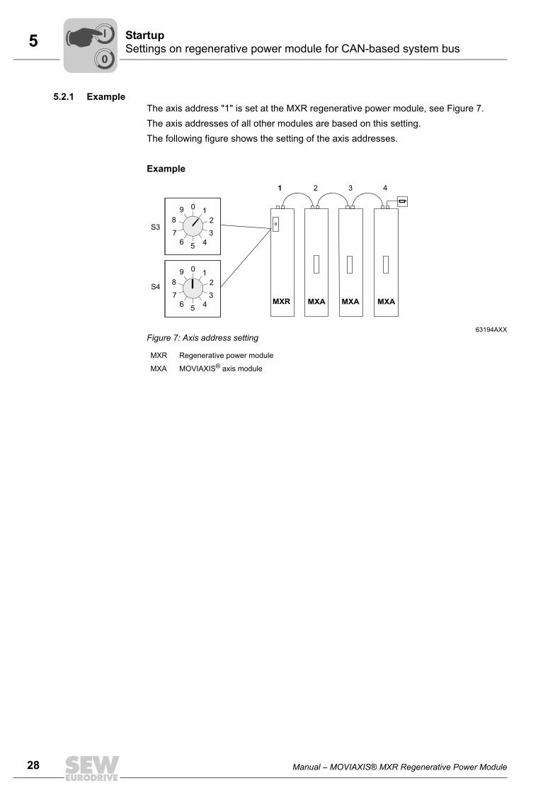
5.2.1 ExampleThe axis address "1" is set at the MXR regenerative power module, see Figure 7.The axis addresses of all other modules are based on this setting.The following figure shows the setting of the axis addresses.
Example
63194AXXFigure 7: Axis address setting
MXR Regenerative power module
MXA MOVIAXIS® axis module
MXR MXA MXA MXA
1 2 3 4
56
7
4
3
2
109
8
56
7
4
3
2
109
8
S3
S4
00
I
Manual – MOVIAXIS® MXR Regenerative Power Module 29
5 Settings on regenerative power module for EtherCAT-based system busStartup
5.3 Settings on regenerative power module for EtherCAT-based system bus XSE24A
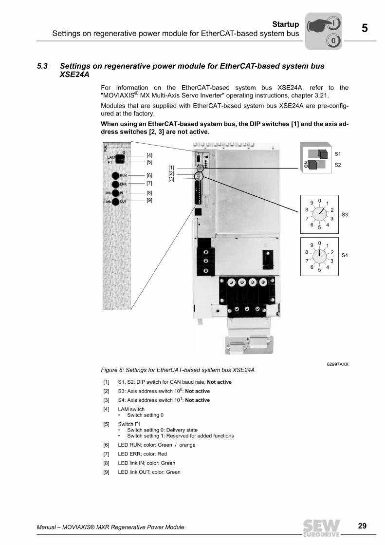
For information on the EtherCAT-based system bus XSE24A, refer to the"MOVIAXIS® MX Multi-Axis Servo Inverter" operating instructions, chapter 3.21.Modules that are supplied with EtherCAT-based system bus XSE24A are pre-config-ured at the factory.When using an EtherCAT-based system bus, the DIP switches [1] and the axis ad-dress switches [2, 3] are not active.
62997AXXFigure 8: Settings for EtherCAT-based system bus XSE24A
[1] S1, S2: DIP switch for CAN baud rate: Not active
[2] S3: Axis address switch 100: Not active
[3] S4: Axis address switch 101: Not active
[4] LAM switch• Switch setting 0
[5] Switch F1• Switch setting 0: Delivery state• Switch setting 1: Reserved for added functions
[6] LED RUN; color: Green / orange
[7] LED ERR; color: Red
[8] LED link IN; color: Green
[9] LED link OUT; color: Green
[2][3]
S1
S2ON
[1]
56
7
4
3
2
109
8
56
7
4
3
2
109
8
S3
S4
XS
E
F1
LAM
I O
RUN
ERR
IN
OUT
OU
TX
31
INX
30
Lnk
Lnk
EtherCAT
XS
E
F1
LAM
I O
RUN
ERR
IN
OUT
OU
TX
31
INX
30
Lnk
Lnk
EtherCAT
[5]
[6]
[7]
[8]
[9]
[4]
00
I
30 Manual – MOVIAXIS® MXR Regenerative Power Module
5 Settings on regenerative power module for EtherCAT fieldbus interface Startup
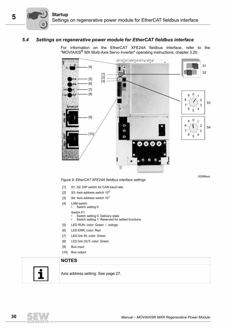
5.4 Settings on regenerative power module for EtherCAT fieldbus interfaceFor information on the EtherCAT XFE24A fieldbus interface, refer to the"MOVIAXIS® MX Multi-Axis Servo Inverter" operating instructions, chapter 3.20.
62998axxFigure 9: EtherCAT XFE24A fieldbus interface settings
[1] S1, S2: DIP switch for CAN baud rate
[2] S3: Axis address switch 100
[3] S4: Axis address switch 101
[4] LAM switch• Switch setting 0
Switch F1• Switch setting 0: Delivery state• Switch setting 1: Reserved for added functions
[5] LED RUN; color: Green / orange
[6] LED ERR; color: Red
[7] LED link IN; color: Green
[8] LED link OUT; color: Green
[9] Bus input
[10] Bus output
[2][3]
S1
S2ON
[1]
56
7
4
3
2
109
8
56
7
4
3
2
109
8
S3
S4
XF
E
F1
I O
RUN
ERR
IN
OUT
OU
TX
31
INX
30
Lnk
Lnk
EtherCAT
[5]
[6]
[7]
[8]
[4]
[9]
[10]
XF
E
F1
I O
RUN
ERR
IN
OUT
OU
TX
31
INX
30
Lnk
Lnk
EtherCAT
NOTES Axis address setting: See page 27.
00
I
Manual – MOVIAXIS® MXR Regenerative Power Module 31
5 Switch-on sequence of MXR regenerative power moduleStartup
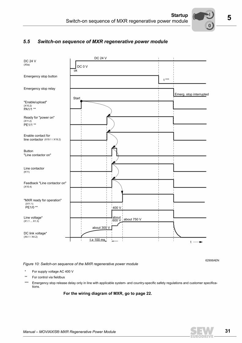
5.5 Switch-on sequence of MXR regenerative power module
For the wiring diagram of MXR, go to page 22.
62906AENFigure 10: Switch-on sequence of the MXR regenerative power module
* For supply voltage AC 400 V
** For control via fieldbus
*** Emergency stop release delay only in line with applicable system- and country-specific safety regulations and customer specifica-tions.
DC 24 V(X5a)
"Enable/upload"(X10.2)
Ready for "power on"(X11.2)
Button
"Line contactor on"
Line contactor(K11)
Feedback "Line contactor on" (X10.4)
t
Enable contact for
line contactor (X19.1 / X19.2)
Line voltage*(X1.1 ... X1.3)
DC link voltage*(X4.1 / X4.2)
Emergency stop relay
Emergency stop button
Start
DC 24 V
DC 0 V
ok
Emerg. stop interrupted
about 750 V
"MXR ready for operation"
PE1/0 **
PE1/1 **
(X11.1)
400 V
t ***
about 600 V
about 300 V
PA1/1 **
t > 100 ms
00
I
32 Manual – MOVIAXIS® MXR Regenerative Power Module
5 Switch-on sequence of MXR regenerative power module Startup
Addendum to the diagramEnable / upload The enable signal is required for operation of the MXR module. It pre-charges the
DC link to about 300 V, see diagram page 31.The in-phase wiring of the components on the line end and the line voltage measure-ment are checked when the DC link voltage drops below 300 V. See error list on page45 ff, error 107.After the "Ready for power on" signal is received, the line contactor is energized.Switching off the MXR module:In normal operation, the MXR module is switched off by withdrawing the "Enable / up-load" signal. This means that the "Internal power on enable" is revoked, which causesthe line contactor to drop out.
Ready for power on
The MXR module sets this signal as soon as the line contactor can be energized.
Enable contact for line contactor
Enable contact for X19 line contactor. The time after which the "Line contactor on" control switch may be activated must belonger than 100 ms.
MXR ready for operation
As soon as the DC link voltage reaches 750 V and no error occurs, the MXR modulesignals "Ready for operation". This signal means that the axes can be enabled.
TroubleshootingIf an error occurs according to chapter 6.2.2 "Table of errors", the "MXR ready for oper-ation" signal (X11.1 / PE1/01)) is withdrawn.In this case, the system must be brought to a standstill in an application-specific emer-gency mode. If the emergency braking resistor option is installed, the axes can be decelerated in acontrolled way. Otherwise the "Output stage enable" of the axes must be revoked.The error responses of the axis modules are listed in the "MOVIAXIS® MX Multi-AxisServo Inverter" operating instructions.
1) Fieldbus operation
00
I
Manual – MOVIAXIS® MXR Regenerative Power Module 33
5 Process data assignment for fieldbus operationStartup
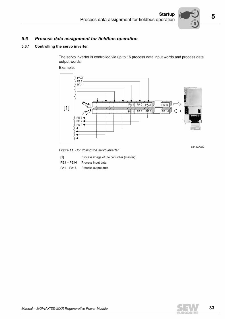
5.6 Process data assignment for fieldbus operation5.6.1 Controlling the servo inverter
The servo inverter is controlled via up to 16 process data input words and process dataoutput words.Example:
63182AXXFigure 11: Controlling the servo inverter
[1] Process image of the controller (master)
PE1 – PE16 Process input data
PA1 – PA16 Process output data
PE 3
PA 3
PE 1
PA 1
PE 2
PA 2
PE 2
PA 2
PE 1
PA 1
PE 3
PA 3
PE 16
PA 16
[1]
00
I
34 Manual – MOVIAXIS® MXR Regenerative Power Module
5 Process data assignment for fieldbus operation Startup
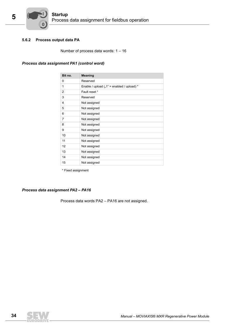
5.6.2 Process output data PA
Number of process data words: 1 – 16
Process data assignment PA1 (control word)
Process data assignment PA2 – PA16
Process data words PA2 – PA16 are not assigned.
Bit no. Meaning
0 Reserved
1 Enable / upload („1“ = enabled / upload) *
2 Fault reset *
3 Reserved
4 Not assigned
5 Not assigned
6 Not assigned
7 Not assigned
8 Not assigned
9 Not assigned
10 Not assigned
11 Not assigned
12 Not assigned
13 Not assigned
14 Not assigned
15 Not assigned
* Fixed assignment
00
I
Manual – MOVIAXIS® MXR Regenerative Power Module 35
5 Process data assignment for fieldbus operationStartup
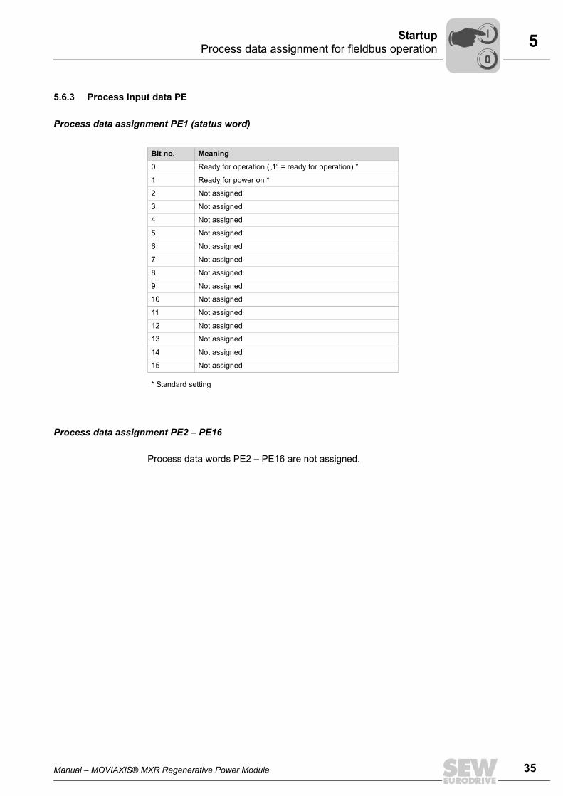
5.6.3 Process input data PE
Process data assignment PE1 (status word)
Process data assignment PE2 – PE16
Process data words PE2 – PE16 are not assigned.
Bit no. Meaning
0 Ready for operation („1“ = ready for operation) *
1 Ready for power on *
2 Not assigned
3 Not assigned
4 Not assigned
5 Not assigned
6 Not assigned
7 Not assigned
8 Not assigned
9 Not assigned
10 Not assigned
11 Not assigned
12 Not assigned
13 Not assigned
14 Not assigned
15 Not assigned
* Standard setting
00
I
36 Manual – MOVIAXIS® MXR Regenerative Power Module
5 Startup of the MXR using MOVITOOLS® MotionStudio Startup
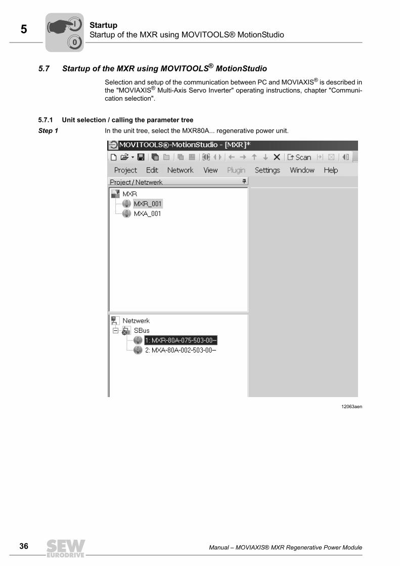
5.7 Startup of the MXR using MOVITOOLS® MotionStudioSelection and setup of the communication between PC and MOVIAXIS® is described inthe "MOVIAXIS® Multi-Axis Servo Inverter" operating instructions, chapter "Communi-cation selection".
5.7.1 Unit selection / calling the parameter treeStep 1 In the unit tree, select the MXR80A... regenerative power unit.
12063aen
00
I
Manual – MOVIAXIS® MXR Regenerative Power Module 37
5 Startup of the MXR using MOVITOOLS® MotionStudioStartup
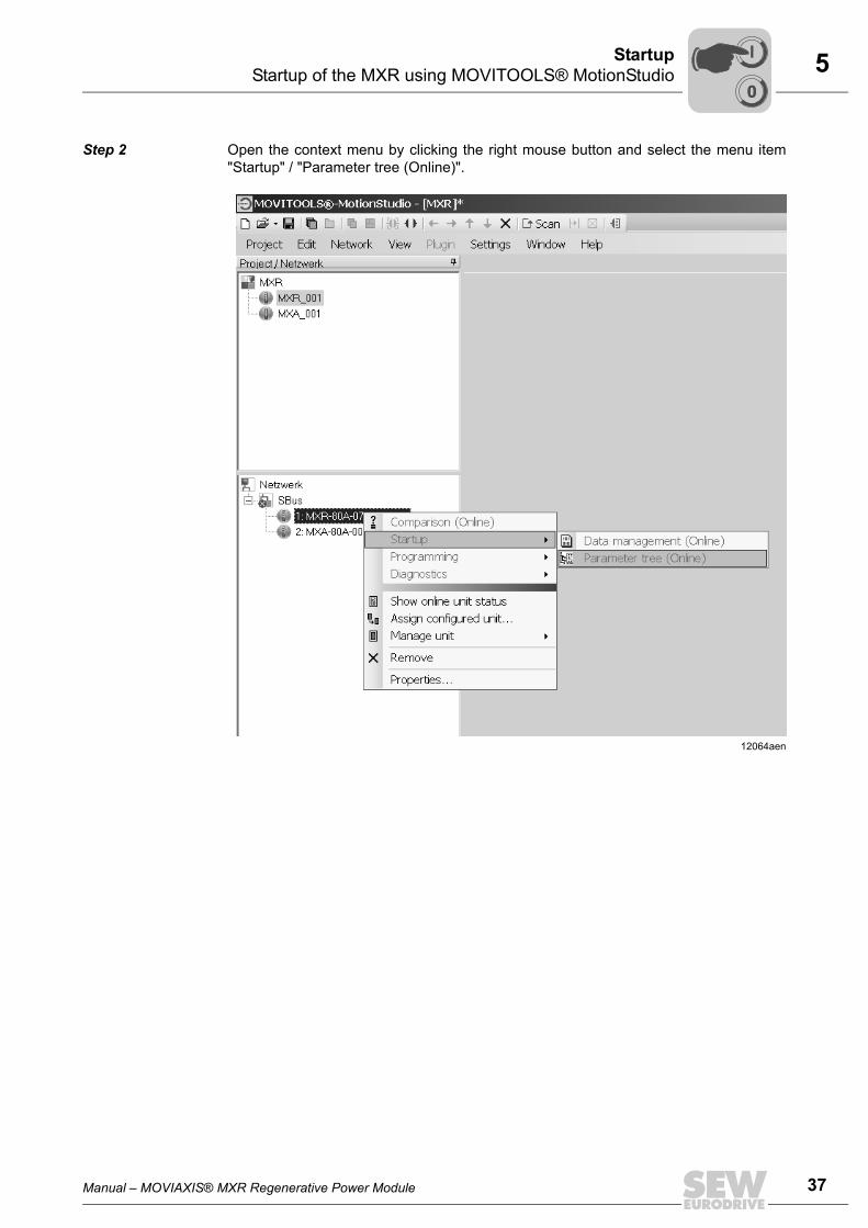
Step 2 Open the context menu by clicking the right mouse button and select the menu item"Startup" / "Parameter tree (Online)".
12064aen
00
I
38 Manual – MOVIAXIS® MXR Regenerative Power Module
5 Startup of the MXR using MOVITOOLS® MotionStudio Startup
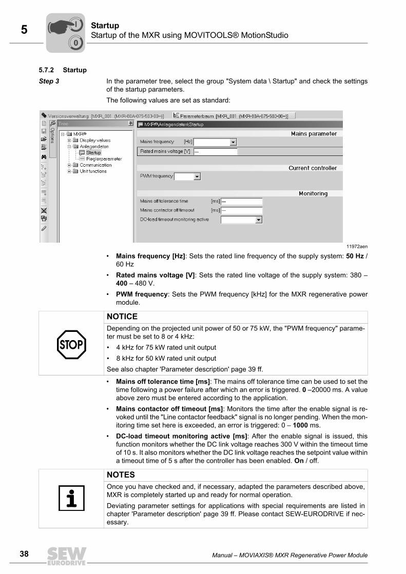
5.7.2 StartupStep 3 In the parameter tree, select the group "System data \ Startup" and check the settings
of the startup parameters. The following values are set as standard:
• Mains frequency [Hz]: Sets the rated line frequency of the supply system: 50 Hz /60 Hz
• Rated mains voltage [V]: Sets the rated line voltage of the supply system: 380 –400 – 480 V.
• PWM frequency: Sets the PWM frequency [kHz] for the MXR regenerative powermodule.
• Mains off tolerance time [ms]: The mains off tolerance time can be used to set thetime following a power failure after which an error is triggered. 0 –20000 ms. A valueabove zero must be entered according to the application.
• Mains contactor off timeout [ms]: Monitors the time after the enable signal is re-voked until the "Line contactor feedback" signal is no longer pending. When the mon-itoring time set here is exceeded, an error is triggered: 0 – 1000 ms.
• DC-load timeout monitoring active [ms]: After the enable signal is issued, thisfunction monitors whether the DC link voltage reaches 300 V within the timeout timeof 10 s. It also monitors whether the DC link voltage reaches the setpoint value withina timeout time of 5 s after the controller has been enabled. On / off.
11972aen
NOTICEDepending on the projected unit power of 50 or 75 kW, the "PWM frequency" parame-ter must be set to 8 or 4 kHz:• 4 kHz for 75 kW rated unit output• 8 kHz for 50 kW rated unit outputSee also chapter 'Parameter description' page 39 ff.
NOTESOnce you have checked and, if necessary, adapted the parameters described above,MXR is completely started up and ready for normal operation. Deviating parameter settings for applications with special requirements are listed inchapter 'Parameter description' page 39 ff. Please contact SEW-EURODRIVE if nec-essary.
00
I
Manual – MOVIAXIS® MXR Regenerative Power Module 39
5 Parameter descriptionStartup
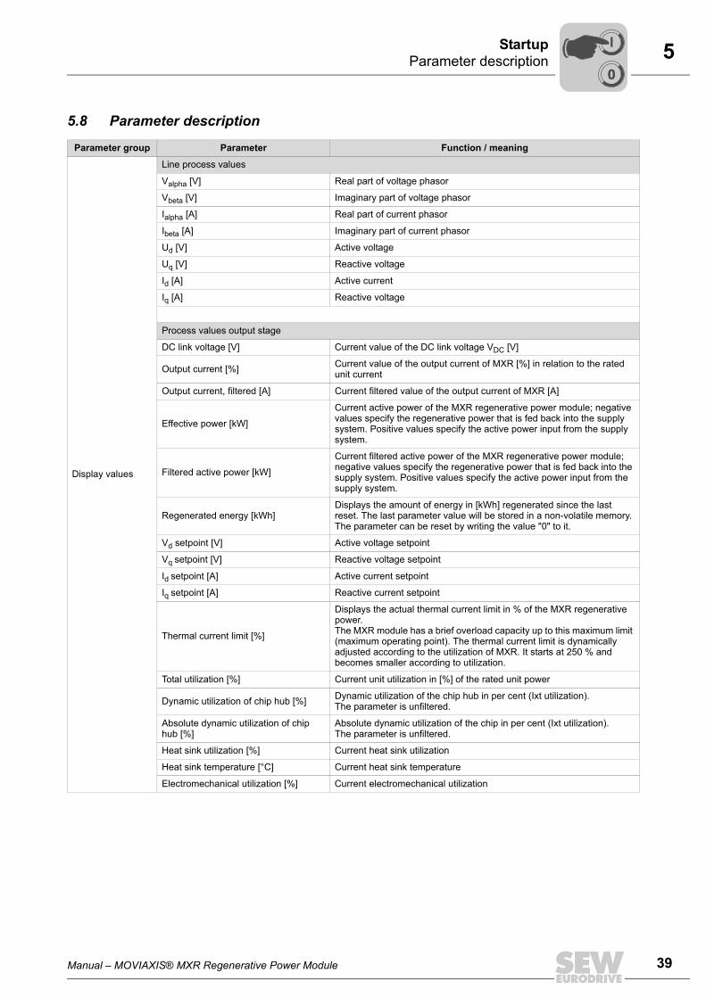
5.8 Parameter description
Parameter group Parameter Function / meaning
Display values
Line process values
Valpha [V] Real part of voltage phasor
Vbeta [V] Imaginary part of voltage phasor
Ialpha [A] Real part of current phasor
Ibeta [A] Imaginary part of current phasor
Ud [V] Active voltage
Uq [V] Reactive voltage
Id [A] Active current
Iq [A] Reactive voltage
Process values output stage
DC link voltage [V] Current value of the DC link voltage VDC [V]
Output current [%] Current value of the output current of MXR [%] in relation to the rated unit current
Output current, filtered [A] Current filtered value of the output current of MXR [A]
Effective power [kW]Current active power of the MXR regenerative power module; negative values specify the regenerative power that is fed back into the supply system. Positive values specify the active power input from the supply system.
Filtered active power [kW]Current filtered active power of the MXR regenerative power module; negative values specify the regenerative power that is fed back into the supply system. Positive values specify the active power input from the supply system.
Regenerated energy [kWh]Displays the amount of energy in [kWh] regenerated since the last reset. The last parameter value will be stored in a non-volatile memory. The parameter can be reset by writing the value "0" to it.
Vd setpoint [V] Active voltage setpoint
Vq setpoint [V] Reactive voltage setpoint
Id setpoint [A] Active current setpoint
Iq setpoint [A] Reactive current setpoint
Thermal current limit [%]
Displays the actual thermal current limit in % of the MXR regenerative power. The MXR module has a brief overload capacity up to this maximum limit (maximum operating point). The thermal current limit is dynamically adjusted according to the utilization of MXR. It starts at 250 % and becomes smaller according to utilization.
Total utilization [%] Current unit utilization in [%] of the rated unit power
Dynamic utilization of chip hub [%] Dynamic utilization of the chip hub in per cent (Ixt utilization).The parameter is unfiltered.
Absolute dynamic utilization of chip hub [%]
Absolute dynamic utilization of the chip in per cent (Ixt utilization).The parameter is unfiltered.
Heat sink utilization [%] Current heat sink utilization
Heat sink temperature [°C] Current heat sink temperature
Electromechanical utilization [%] Current electromechanical utilization
00
I
40 Manual – MOVIAXIS® MXR Regenerative Power Module
5 Parameter description Startup
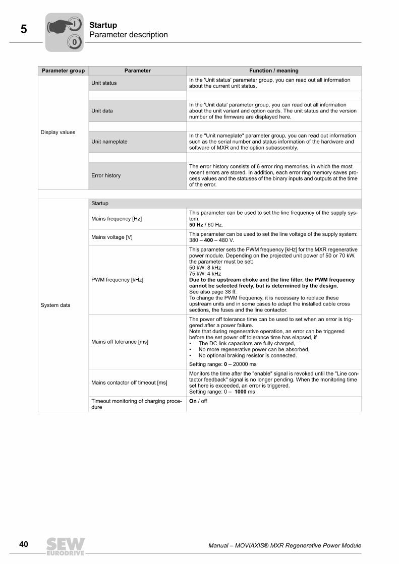
Display values
Unit status In the 'Unit status' parameter group, you can read out all information about the current unit status.
Unit dataIn the 'Unit data' parameter group, you can read out all information about the unit variant and option cards. The unit status and the version number of the firmware are displayed here.
Unit nameplateIn the "Unit nameplate" parameter group, you can read out information such as the serial number and status information of the hardware and software of MXR and the option subassembly.
Error historyThe error history consists of 6 error ring memories, in which the most recent errors are stored. In addition, each error ring memory saves pro-cess values and the statuses of the binary inputs and outputs at the time of the error.
System data
Startup
Mains frequency [Hz]This parameter can be used to set the line frequency of the supply sys-tem:50 Hz / 60 Hz.
Mains voltage [V] This parameter can be used to set the line voltage of the supply system: 380 – 400 – 480 V.
PWM frequency [kHz]
This parameter sets the PWM frequency [kHz] for the MXR regenerative power module. Depending on the projected unit power of 50 or 70 kW, the parameter must be set:50 kW: 8 kHz75 kW: 4 kHzDue to the upstream choke and the line filter, the PWM frequency cannot be selected freely, but is determined by the design.See also page 38 ff. To change the PWM frequency, it is necessary to replace these upstream units and in some cases to adapt the installed cable cross sections, the fuses and the line contactor.
Mains off tolerance [ms]
The power off tolerance time can be used to set when an error is trig-gered after a power failure. Note that during regenerative operation, an error can be triggered before the set power off tolerance time has elapsed, if• The DC link capacitors are fully charged,• No more regenerative power can be absorbed,• No optional braking resistor is connected.Setting range: 0 – 20000 ms
Mains contactor off timeout [ms]Monitors the time after the "enable" signal is revoked until the "Line con-tactor feedback" signal is no longer pending. When the monitoring time set here is exceeded, an error is triggered. Setting range: 0 – 1000 ms
Timeout monitoring of charging proce-dure
On / off
Parameter group Parameter Function / meaning
00
I
Manual – MOVIAXIS® MXR Regenerative Power Module 41
5 Parameter descriptionStartup
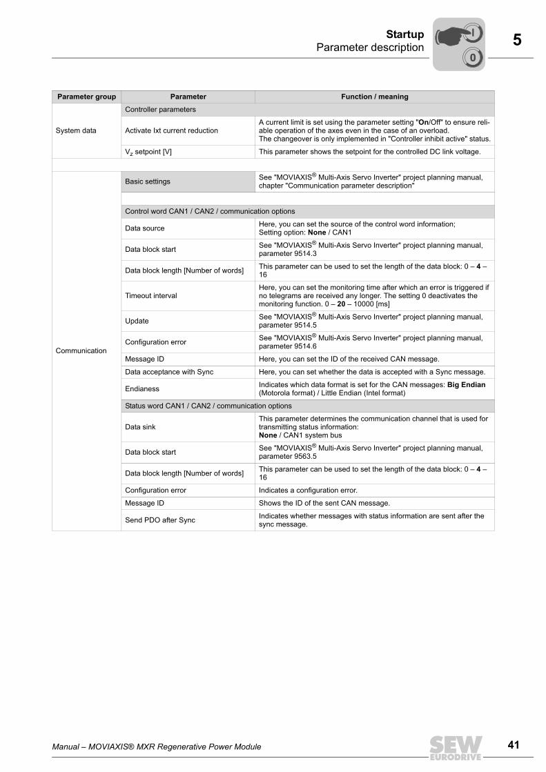
System data
Controller parameters
Activate Ixt current reductionA current limit is set using the parameter setting "On/Off" to ensure reli-able operation of the axes even in the case of an overload.The changeover is only implemented in "Controller inhibit active" status.
Vz setpoint [V] This parameter shows the setpoint for the controlled DC link voltage.
Communication
Basic settings See "MOVIAXIS® Multi-Axis Servo Inverter" project planning manual, chapter "Communication parameter description"
Control word CAN1 / CAN2 / communication options
Data source Here, you can set the source of the control word information; Setting option: None / CAN1
Data block start See "MOVIAXIS® Multi-Axis Servo Inverter" project planning manual, parameter 9514.3
Data block length [Number of words] This parameter can be used to set the length of the data block: 0 – 4 – 16
Timeout intervalHere, you can set the monitoring time after which an error is triggered if no telegrams are received any longer. The setting 0 deactivates the monitoring function. 0 – 20 – 10000 [ms]
Update See "MOVIAXIS® Multi-Axis Servo Inverter" project planning manual, parameter 9514.5
Configuration error See "MOVIAXIS® Multi-Axis Servo Inverter" project planning manual, parameter 9514.6
Message ID Here, you can set the ID of the received CAN message.
Data acceptance with Sync Here, you can set whether the data is accepted with a Sync message.
Endianess Indicates which data format is set for the CAN messages: Big Endian (Motorola format) / Little Endian (Intel format)
Status word CAN1 / CAN2 / communication options
Data sinkThis parameter determines the communication channel that is used for transmitting status information:None / CAN1 system bus
Data block start See "MOVIAXIS® Multi-Axis Servo Inverter" project planning manual, parameter 9563.5
Data block length [Number of words] This parameter can be used to set the length of the data block: 0 – 4 – 16
Configuration error Indicates a configuration error.
Message ID Shows the ID of the sent CAN message.
Send PDO after Sync Indicates whether messages with status information are sent after the sync message.
Parameter group Parameter Function / meaning
00
I
42 Manual – MOVIAXIS® MXR Regenerative Power Module
5 Parameter description Startup
Communication
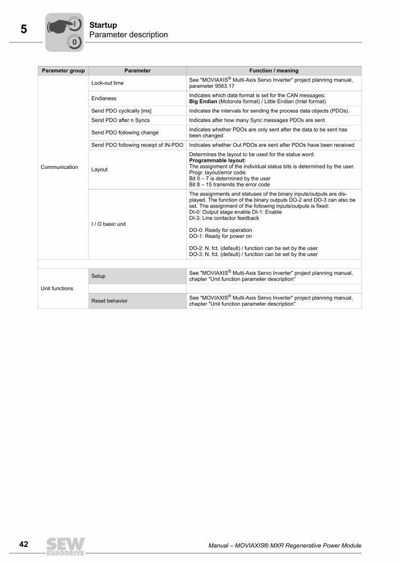
Lock-out time See "MOVIAXIS® Multi-Axis Servo Inverter" project planning manual, parameter 9563.17
Endianess Indicates which data format is set for the CAN messages:Big Endian (Motorola format) / Little Endian (Intel format)
Send PDO cyclically [ms] Indicates the intervals for sending the process data objects (PDOs).
Send PDO after n Syncs Indicates after how many Sync messages PDOs are sent
Send PDO following change Indicates whether PDOs are only sent after the data to be sent has been changed
Send PDO following receipt of IN-PDO Indicates whether Out PDOs are sent after PDOs have been received
Layout
Determines the layout to be used for the status word:Programmable layout: The assignment of the individual status bits is determined by the user.Progr. layout/error code: Bit 0 – 7 is determined by the userBit 8 – 15 transmits the error code
I / O basic unit
The assignments and statuses of the binary inputs/outputs are dis-played. The function of the binary outputs DO-2 and DO-3 can also be set. The assignment of the following inputs/outputs is fixed:DI-0: Output stage enable DI-1: EnableDI-3: Line contactor feedback
DO-0: Ready for operationDO-1: Ready for power on
DO-2: N. fct. (default) / function can be set by the userDO-3: N. fct. (default) / function can be set by the user
Unit functions
Setup See "MOVIAXIS® Multi-Axis Servo Inverter" project planning manual, chapter "Unit function parameter description"
Reset behavior See "MOVIAXIS® Multi-Axis Servo Inverter" project planning manual, chapter "Unit function parameter description"
Parameter group Parameter Function / meaning
00
I
Manual – MOVIAXIS® MXR Regenerative Power Module 43
6 General informationOperation
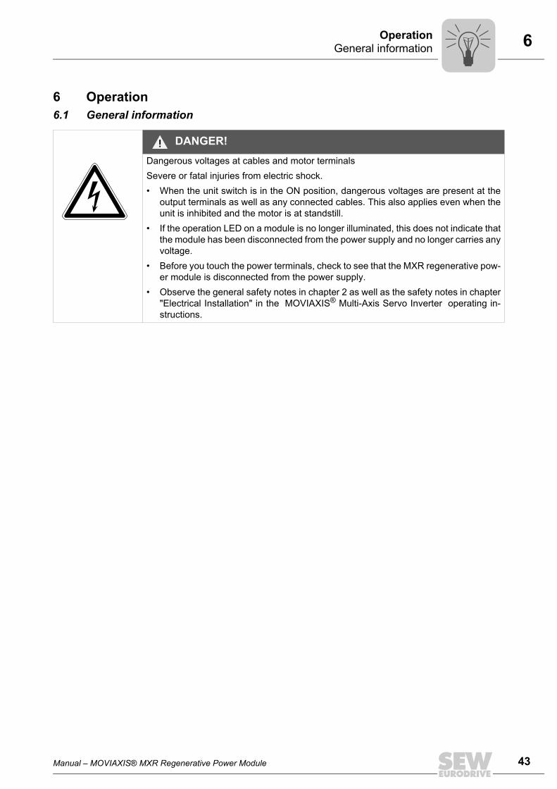
6 Operation6.1 General information
DANGER!Dangerous voltages at cables and motor terminalsSevere or fatal injuries from electric shock.• When the unit switch is in the ON position, dangerous voltages are present at the
output terminals as well as any connected cables. This also applies even when theunit is inhibited and the motor is at standstill.
• If the operation LED on a module is no longer illuminated, this does not indicate thatthe module has been disconnected from the power supply and no longer carries anyvoltage.
• Before you touch the power terminals, check to see that the MXR regenerative pow-er module is disconnected from the power supply.
• Observe the general safety notes in chapter 2 as well as the safety notes in chapter"Electrical Installation" in the MOVIAXIS® Multi-Axis Servo Inverter operating in-structions.
44 Manual – MOVIAXIS® MXR Regenerative Power Module
6 Operating displays and errors of the MXR regenerative power module Operation
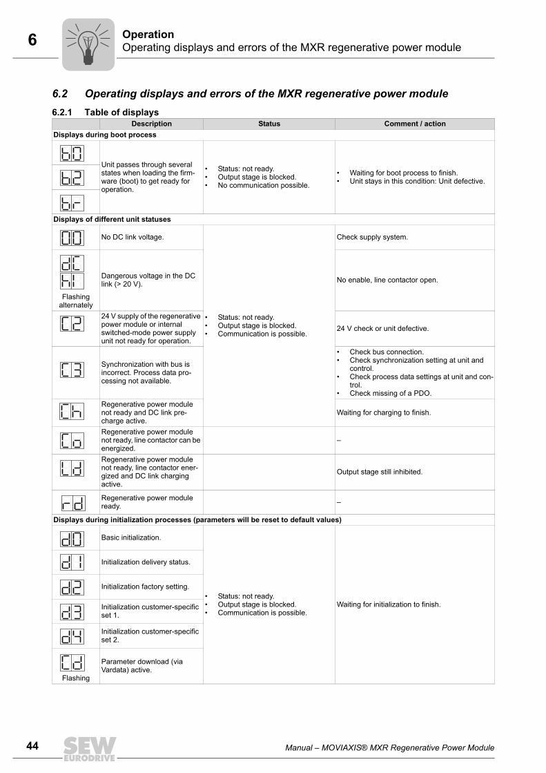
6.2 Operating displays and errors of the MXR regenerative power module6.2.1 Table of displays
Description Status Comment / actionDisplays during boot process
Unit passes through several states when loading the firm-ware (boot) to get ready for operation.
• Status: not ready.• Output stage is blocked.• No communication possible.
• Waiting for boot process to finish.• Unit stays in this condition: Unit defective.
Displays of different unit statuses
No DC link voltage.
• Status: not ready.• Output stage is blocked.• Communication is possible.
Check supply system.
Flashing alternately
Dangerous voltage in the DC link (> 20 V). No enable, line contactor open.
24 V supply of the regenerative power module or internal switched-mode power supply unit not ready for operation.
24 V check or unit defective.
Synchronization with bus is incorrect. Process data pro-cessing not available.
• Check bus connection.• Check synchronization setting at unit and
control.• Check process data settings at unit and con-
trol.• Check missing of a PDO.
Regenerative power module not ready and DC link pre-charge active.
Waiting for charging to finish.
Regenerative power module not ready, line contactor can be energized.
–
Regenerative power module not ready, line contactor ener-gized and DC link charging active.
Output stage still inhibited.
Regenerative power module ready. –
Displays during initialization processes (parameters will be reset to default values)
Basic initialization.
• Status: not ready.• Output stage is blocked.• Communication is possible.
Waiting for initialization to finish.
Initialization delivery status.
Initialization factory setting.
Initialization customer-specific set 1.
Initialization customer-specific set 2.
Flashing
Parameter download (via Vardata) active.
Manual – MOVIAXIS® MXR Regenerative Power Module 45
6 Operating displays and errors of the MXR regenerative power moduleOperation
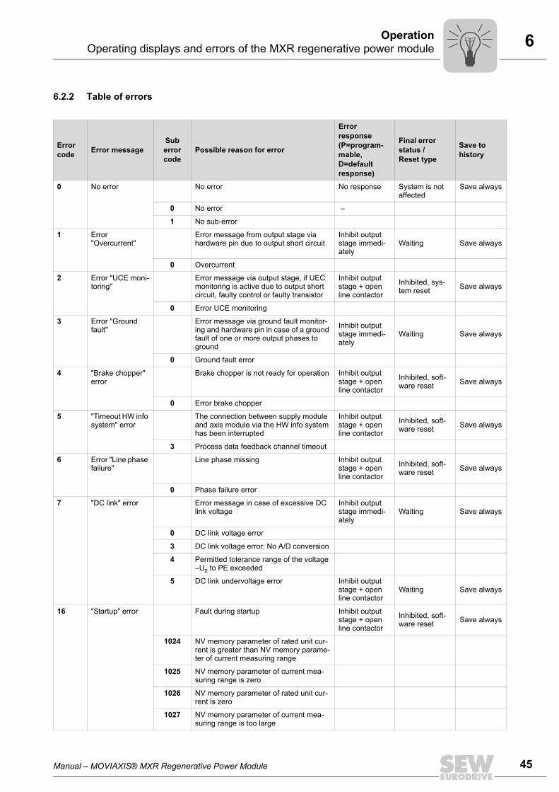
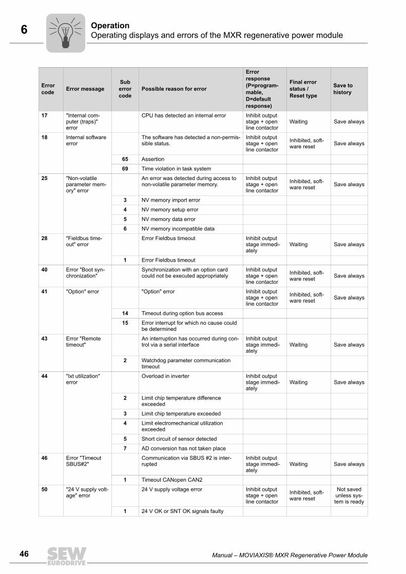
6.2.2 Table of errors
Error code Error message
Sub error code
Possible reason for error
Error response (P=program-mable, D=default response)
Final error status / Reset type
Save to history
0 No error No error No response System is not affected
Save always
0 No error –
1 No sub-error
1 Error "Overcurrent"
Error message from output stage via hardware pin due to output short circuit
Inhibit output stage immedi-ately
Waiting Save always
0 Overcurrent
2 Error "UCE moni-toring"
Error message via output stage, if UEC monitoring is active due to output short circuit, faulty control or faulty transistor
Inhibit output stage + open line contactor
Inhibited, sys-tem reset Save always
0 Error UCE monitoring
3 Error "Ground fault"
Error message via ground fault monitor-ing and hardware pin in case of a ground fault of one or more output phases to ground
Inhibit output stage immedi-ately
Waiting Save always
0 Ground fault error
4 "Brake chopper" error
Brake chopper is not ready for operation Inhibit output stage + open line contactor
Inhibited, soft-ware reset Save always
0 Error brake chopper
5 "Timeout HW info system" error
The connection between supply module and axis module via the HW info system has been interrupted
Inhibit output stage + open line contactor
Inhibited, soft-ware reset Save always
3 Process data feedback channel timeout
6 Error "Line phase failure"
Line phase missing Inhibit output stage + open line contactor
Inhibited, soft-ware reset Save always
0 Phase failure error
7 "DC link" error Error message in case of excessive DC link voltage
Inhibit output stage immedi-ately
Waiting Save always
0 DC link voltage error
3 DC link voltage error: No A/D conversion
4 Permitted tolerance range of the voltage –Uz to PE exceeded
5 DC link undervoltage error Inhibit output stage + open line contactor
Waiting Save always
16 "Startup" error Fault during startup Inhibit output stage + open line contactor
Inhibited, soft-ware reset Save always
1024 NV memory parameter of rated unit cur-rent is greater than NV memory parame-ter of current measuring range
1025 NV memory parameter of current mea-suring range is zero
1026 NV memory parameter of rated unit cur-rent is zero
1027 NV memory parameter of current mea-suring range is too large
46 Manual – MOVIAXIS® MXR Regenerative Power Module
6 Operating displays and errors of the MXR regenerative power module Operation
17 "Internal com-puter (traps)" error
CPU has detected an internal error Inhibit output stage + open line contactor
Waiting Save always
18 Internal software error
The software has detected a non-permis-sible status.
Inhibit output stage + open line contactor
Inhibited, soft-ware reset Save always
65 Assertion
69 Time violation in task system
25 "Non-volatile parameter mem-ory" error
An error was detected during access to non-volatile parameter memory.
Inhibit output stage + open line contactor
Inhibited, soft-ware reset Save always
3 NV memory import error
4 NV memory setup error
5 NV memory data error
6 NV memory incompatible data
28 "Fieldbus time-out" error
Error Fieldbus timeout Inhibit output stage immedi-ately
Waiting Save always
1 Error Fieldbus timeout
40 Error "Boot syn-chronization"
Synchronization with an option card could not be executed appropriately
Inhibit output stage + open line contactor
Inhibited, soft-ware reset Save always
41 "Option" error "Option" error Inhibit output stage + open line contactor
Inhibited, soft-ware reset Save always
14 Timeout during option bus access
15 Error interrupt for which no cause could be determined
43 Error "Remote timeout"
An interruption has occurred during con-trol via a serial interface
Inhibit output stage immedi-ately
Waiting Save always
2 Watchdog parameter communication timeout
44 "Ixt utilization" error
Overload in inverter Inhibit output stage immedi-ately
Waiting Save always
2 Limit chip temperature difference exceeded
3 Limit chip temperature exceeded
4 Limit electromechanical utilization exceeded
5 Short circuit of sensor detected
7 AD conversion has not taken place
46 Error "Timeout SBUS#2"
Communication via SBUS #2 is inter-rupted
Inhibit output stage immedi-ately
Waiting Save always
1 Timeout CANopen CAN2
50 "24 V supply volt-age" error
24 V supply voltage error Inhibit output stage + open line contactor
Inhibited, soft-ware reset
Not saved unless sys-tem is ready
1 24 V OK or SNT OK signals faulty
Error code Error message
Sub error code
Possible reason for error
Error response (P=program-mable, D=default response)
Final error status / Reset type
Save to history
Manual – MOVIAXIS® MXR Regenerative Power Module 47
6 Operating displays and errors of the MXR regenerative power moduleOperation
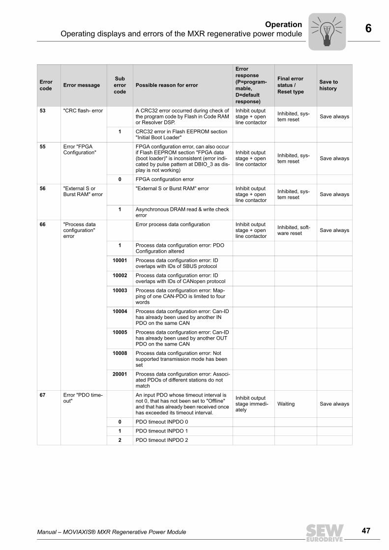
53 "CRC flash- error A CRC32 error occurred during check of the program code by Flash in Code RAM or Resolver DSP.
Inhibit output stage + open line contactor
Inhibited, sys-tem reset Save always
1 CRC32 error in Flash EEPROM section "Initial Boot Loader"
55 Error "FPGA Configuration"
FPGA configuration error, can also occur if Flash EEPROM section "FPGA data (boot loader)" is inconsistent (error indi-cated by pulse pattern at DBIO_3 as dis-play is not working)
Inhibit output stage + open line contactor
Inhibited, sys-tem reset Save always
0 FPGA configuration error
56 "External S or Burst RAM" error
"External S or Burst RAM" error Inhibit output stage + open line contactor
Inhibited, sys-tem reset Save always
1 Asynchronous DRAM read & write check error
66 "Process data configuration" error
Error process data configuration Inhibit output stage + open line contactor
Inhibited, soft-ware reset Save always
1 Process data configuration error: PDO Configuration altered
10001 Process data configuration error: ID overlaps with IDs of SBUS protocol
10002 Process data configuration error: ID overlaps with IDs of CANopen protocol
10003 Process data configuration error: Map-ping of one CAN-PDO is limited to four words
10004 Process data configuration error: Can-ID has already been used by another IN PDO on the same CAN
10005 Process data configuration error: Can-ID has already been used by another OUT PDO on the same CAN
10008 Process data configuration error: Not supported transmission mode has been set
20001 Process data configuration error: Associ-ated PDOs of different stations do not match
67 Error "PDO time-out"
An input PDO whose timeout interval is not 0, that has not been set to "Offline" and that has already been received once has exceeded its timeout interval.
Inhibit output stage immedi-ately
Waiting Save always
0 PDO timeout INPDO 0
1 PDO timeout INPDO 1
2 PDO timeout INPDO 2
Error code Error message
Sub error code
Possible reason for error
Error response (P=program-mable, D=default response)
Final error status / Reset type
Save to history
48 Manual – MOVIAXIS® MXR Regenerative Power Module
6 Operating displays and errors of the MXR regenerative power module Operation
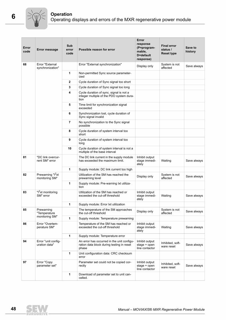
68 Error "External synchronization"
Error "External synchronization" Display only System is not affected Save always
1 Non-permitted Sync source parameter-ized
2 Cycle duration of Sync signal too short
3 Cycle duration of Sync signal too long
4 Cycle duration of sync. signal is not a integer multiple of the PDO system dura-tion
5 Time limit for synchronization signal exceeded
6 Synchronization lost, cycle duration of Sync signal invalid
7 No synchronization to the Sync signal possible
8 Cycle duration of system interval too short
9 Cycle duration of system interval too long
10 Cycle duration of system interval is not a multiple of the base interval
81 "DC link overcur-rent SM" error
The DC link current in the supply module has exceeded the maximum limit.
Inhibit output stage immedi-ately
Waiting Save always
1 Supply module: DC link current too high
82 Prewarning "I2xt monitoring SM"
Utilization of the SM has reached the prewarning level Display only System is not
affected Save always
1 Supply module: Pre-warning Ixt utiliza-tion
83 "I2xt monitoring SM" error
Utilization of the SM has reached or exceeded the cut-off threshold
Inhibit output stage immedi-ately
Waiting Save always
1 Supply module: Error Ixt utilization
85 Prewarning "Temperature monitoring SM"
The temperature of the SM approaches the cut-off threshold Display only System is not
affected Save always
1 Supply module: Temperature prewarning
86 Error "Overtem-perature SM"
Temperature of the SM has reached or exceeded the cut-off threshold
Inhibit output stage immedi-ately
Waiting Save always
1 Supply module: Temperature error
94 Error "unit config-uration data"
An error has occurred in the unit configu-ration data block during testing in reset phase
Inhibit output stage + open line contactor
Inhibited, soft-ware reset Save always
1 Unit configuration data: CRC checksum error
97 Error "Copy parameter set"
Parameter set could not be copied cor-rectly
Inhibit output stage + open line contactor
Inhibited, soft-ware reset Save always
1 Download of parameter set to unit can-celled.
Error code Error message
Sub error code
Possible reason for error
Error response (P=program-mable, D=default response)
Final error status / Reset type
Save to history

Manual – MOVIAXIS® MXR Regenerative Power Module 49
6 Operating displays and errors of the MXR regenerative power moduleOperation
107 Line component error
The firmware has detected an error in one of the line components (choke, line filter, line contactor).
Inhibit output stage + open line contactor
Inhibited, soft-ware reset Save always
1 Line contactor feedback contact error
2 Timeout when opening the line contactor
3 Ground fault error
4 The supply cables are interchanged
5 A supply cable is missing or output stage is faulty
197 "Power failure" error
The firmware has detected a power fail-ure
0 Power failure error Inhibit output stage + open line contactor
Waiting Save always
1 Line overvoltage error at ≥ 528 V Inhibit output stage immedi-
atelyWaiting Save always
2 Line undervoltage error at ≤ 325 V Inhibit output stage immedi-
atelyWaiting Save always
3 Line quality error at VN ± 10% Display only Auto reset Save always
199 "DC link charge" error
An error has occurred in the sequence control for DC link charging
Inhibit output stage + open line contactor
Inhibited, soft-ware reset Save always
1 Timeout during pre-charging of the DC link to voltage setpoint
2 Timeout upon reaching the voltage set-point (energized line contactor)
3 Timeout during charging of the DC link to voltage setpoint
Error code Error message
Sub error code
Possible reason for error
Error response (P=program-mable, D=default response)
Final error status / Reset type
Save to history

50 Manual – MOVIAXIS® MXR Regenerative Power Module
7 Technical data of the MXR regenerative power module Technical Data
7 Technical Data7.1 Technical data of the MXR regenerative power module7.1.1 General technical data
Unit Regenerative power moduleMXR
Environmental conditions
Ambient temperature (MXR) °C 0 – +45
Storage temperature °C –25 – +70
Climate class – EN 60721-3-3, class 3K3
Enclosure EN 60529 (NEMA1)1)
1) The covers on the left and right end of the unit system must be equipped with touch guard covers. All cablelugs must be insulated.
– IP20 to EN 60529
Operating mode – Continuous duty (EN 60146-1-1 and 1-3)
Type of cooling – DIN 41751 forced cooling(temperature-controlled fan)
Overvoltage category – III according to IEC 60664-1 (VDE0110-1)
Pollution class – II according to IEC 60664-1 (VDE 0110-1)
Installation altitude –
Up to h ≤ 1000 m, there are no restrictions.The following restrictions apply at heights ≥ 1000 m:– From 1,000 m to max. 2000 m:
IN reduction by 1% per 100 m
Storage life –Up to 2 years without any special measures, after that see chapter "Service" in the "MOVIAXIS® MX Multi-Axis Servo Inverter" operating instructions.
Operating conditions
Interference immunity – Meets EN 61800-3
Interference emission with EMC-compli-ant installation – Category "C2" according to 61800-3
Power loss at nominal capacity W 1000
No. of times power may be switched on/off min–1 < 1
Minimum switch-off time for "Power off" s > 10
Ready for operation after "Power on" s ≤ 20
Mass kg 22
Dimensions:
B mm 210
H mm 400
T mm 254
NOTES
Note the minimum switch-off time for "Power off".
Pi
fkVA
Hz
n
Manual – MOVIAXIS® MXR Regenerative Power Module 51
7 Technical data of the MXR regenerative power moduleTechnical Data
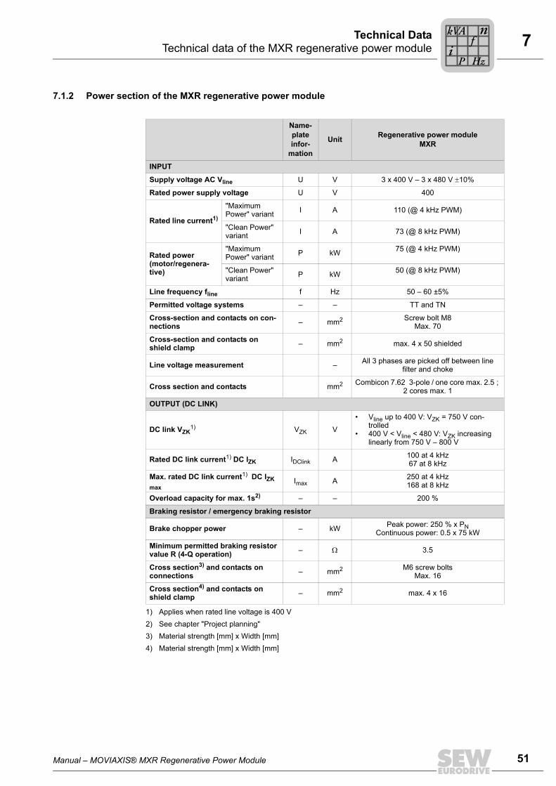
7.1.2 Power section of the MXR regenerative power module
Name-plate infor-
mation
Unit Regenerative power moduleMXR
INPUT
Supply voltage AC Vline U V 3 x 400 V – 3 x 480 V ±10%
Rated power supply voltage U V 400
Rated line current1)
1) Applies when rated line voltage is 400 V
"Maximum Power" variant I A 110 (@ 4 kHz PWM)
"Clean Power" variant I A 73 (@ 8 kHz PWM)
Rated power (motor/regenera-tive)
"Maximum Power" variant P kW 75 (@ 4 kHz PWM)
"Clean Power" variant P kW 50 (@ 8 kHz PWM)
Line frequency fline f Hz 50 – 60 ±5%
Permitted voltage systems – – TT and TN
Cross-section and contacts on con-nections – mm2 Screw bolt M8
Max. 70
Cross-section and contacts on shield clamp – mm2 max. 4 x 50 shielded
Line voltage measurement – All 3 phases are picked off between line filter and choke
Cross section and contacts mm2 Combicon 7.62 3-pole / one core max. 2.5 ; 2 cores max. 1
OUTPUT (DC LINK)
DC link VZK1) VZK V
• Vline up to 400 V: VZK = 750 V con-trolled
• 400 V < Vline < 480 V: VZK increasing linearly from 750 V – 800 V
Rated DC link current1) DC IZK IDClink A 100 at 4 kHz67 at 8 kHz
Max. rated DC link current1) DC IZK max
Imax A 250 at 4 kHz168 at 8 kHz
Overload capacity for max. 1s2)
2) See chapter "Project planning"
– – 200 %
Braking resistor / emergency braking resistor
Brake chopper power – kW Peak power: 250 % x PN Continuous power: 0.5 x 75 kW
Minimum permitted braking resistor value R (4-Q operation) – Ω 3.5
Cross section3) and contacts on connections
3) Material strength [mm] x Width [mm]
– mm2 M6 screw boltsMax. 16
Cross section4) and contacts on shield clamp
4) Material strength [mm] x Width [mm]
– mm2 max. 4 x 16
Pi
fkVA
Hz
n
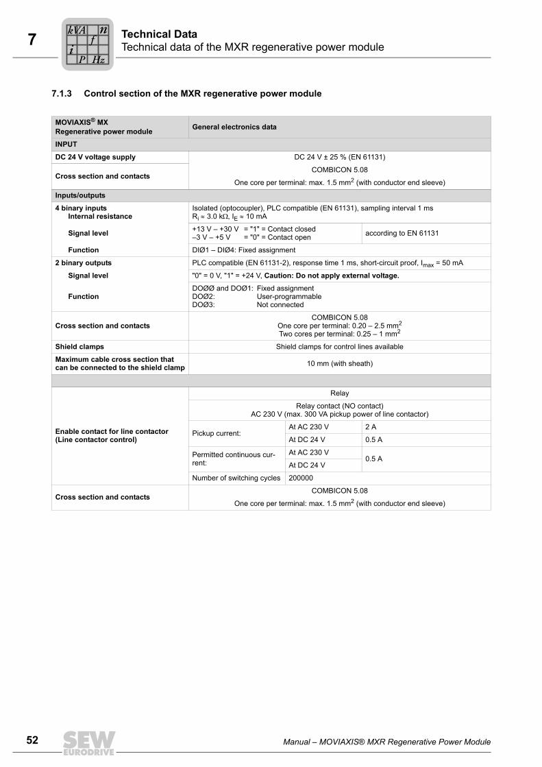
52 Manual – MOVIAXIS® MXR Regenerative Power Module
7 Technical data of the MXR regenerative power module Technical Data
7.1.3 Control section of the MXR regenerative power module
MOVIAXIS® MX Regenerative power module General electronics data
INPUT
DC 24 V voltage supply DC 24 V ± 25 % (EN 61131)
Cross section and contactsCOMBICON 5.08
One core per terminal: max. 1.5 mm2 (with conductor end sleeve)
Inputs/outputs
4 binary inputsInternal resistance
Isolated (optocoupler), PLC compatible (EN 61131), sampling interval 1 msRi ≈ 3.0 kΩ, IE ≈ 10 mA
Signal level +13 V – +30 V = "1" = Contact closed–3 V – +5 V = "0" = Contact open according to EN 61131
Function DIØ1 – DIØ4: Fixed assignment
2 binary outputs PLC compatible (EN 61131-2), response time 1 ms, short-circuit proof, Imax = 50 mA
Signal level "0" = 0 V, "1" = +24 V, Caution: Do not apply external voltage.
FunctionDOØØ and DOØ1: Fixed assignmentDOØ2: User-programmableDOØ3: Not connected
Cross section and contactsCOMBICON 5.08
One core per terminal: 0.20 – 2.5 mm2
Two cores per terminal: 0.25 – 1 mm2
Shield clamps Shield clamps for control lines available
Maximum cable cross section that can be connected to the shield clamp 10 mm (with sheath)
Enable contact for line contactor (Line contactor control)
Relay
Relay contact (NO contact)AC 230 V (max. 300 VA pickup power of line contactor)
Pickup current:At AC 230 V 2 A
At DC 24 V 0.5 A
Permitted continuous cur-rent:
At AC 230 V0.5 A
At DC 24 V
Number of switching cycles 200000
Cross section and contactsCOMBICON 5.08
One core per terminal: max. 1.5 mm2 (with conductor end sleeve)
Pi
fkVA
Hz
n
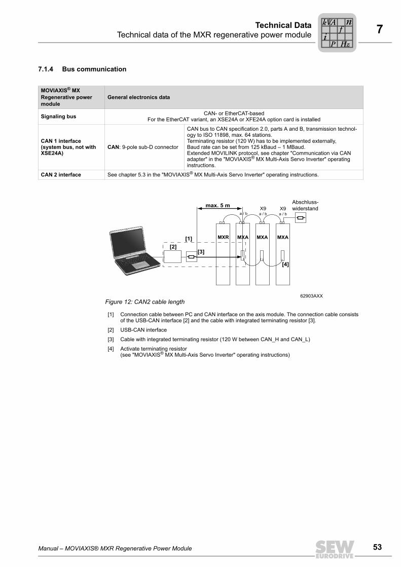
Manual – MOVIAXIS® MXR Regenerative Power Module 53
7 Technical data of the MXR regenerative power moduleTechnical Data
7.1.4 Bus communication
MOVIAXIS® MX Regenerative power module
General electronics data
Signaling bus CAN- or EtherCAT-basedFor the EtherCAT variant, an XSE24A or XFE24A option card is installed
CAN 1 interface(system bus, not with XSE24A)
CAN: 9-pole sub-D connector
CAN bus to CAN specification 2.0, parts A and B, transmission technol-ogy to ISO 11898, max. 64 stations.Terminating resistor (120 W) has to be implemented externally,Baud rate can be set from 125 kBaud – 1 MBaud.Extended MOVILINK protocol, see chapter "Communication via CAN adapter" in the "MOVIAXIS® MX Multi-Axis Servo Inverter" operating instructions.
CAN 2 interface See chapter 5.3 in the "MOVIAXIS® MX Multi-Axis Servo Inverter" operating instructions.
62903AXXFigure 12: CAN2 cable length
[1] Connection cable between PC and CAN interface on the axis module. The connection cable consists of the USB-CAN interface [2] and the cable with integrated terminating resistor [3].
[2] USB-CAN interface
[3] Cable with integrated terminating resistor (120 W between CAN_H and CAN_L)
[4] Activate terminating resistor (see "MOVIAXIS® MX Multi-Axis Servo Inverter" operating instructions)
MXR
max. 5 m
MXA MXA MXA
X9a / ba / b
X9a / b
Abschluss-
widerstand
[2][3]
[1]
[4]
Pi
fkVA
Hz
n
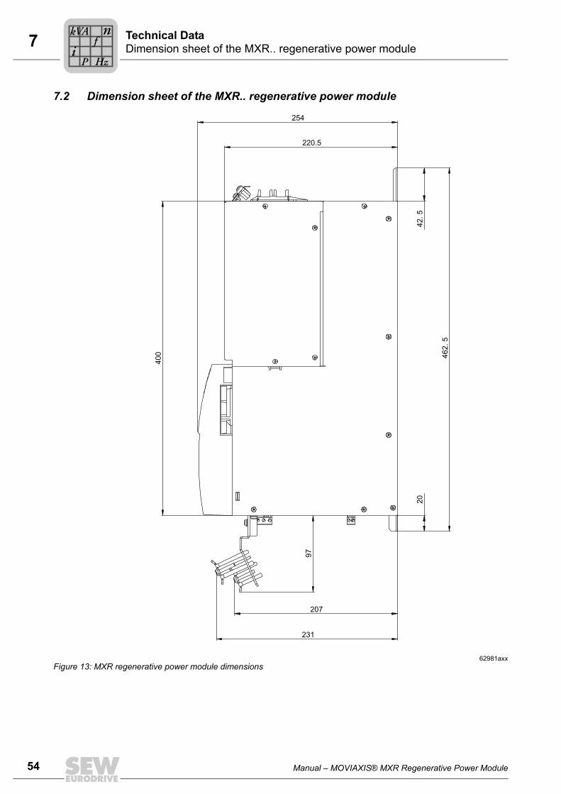
54 Manual – MOVIAXIS® MXR Regenerative Power Module
7 Dimension sheet of the MXR.. regenerative power module Technical Data
7.2 Dimension sheet of the MXR.. regenerative power module
62981axxFigure 13: MXR regenerative power module dimensions
462. 5
20
42
. 5
220.5
254
40
0
97
231
207
Pi
fkVA
Hz
n

Manual – MOVIAXIS® MXR Regenerative Power Module 55
7 Drilling template of the MXR.. regenerative power moduleTechnical Data
7.3 Drilling template of the MXR.. regenerative power module
1) Position of tapped hole2) The dimensions are listed in the following table
06695axxFigure 14: Drilling template of MXR regenerative power module
2)
2)
2)
2)
MOVIAXIS® MX
Dimensions for housing - MOVIAXIS® MX back views
A B C D
[mm] [mm] [mm] [mm]
MXR regenerative power module 210 180 453 462.5
Pi
fkVA
Hz
n
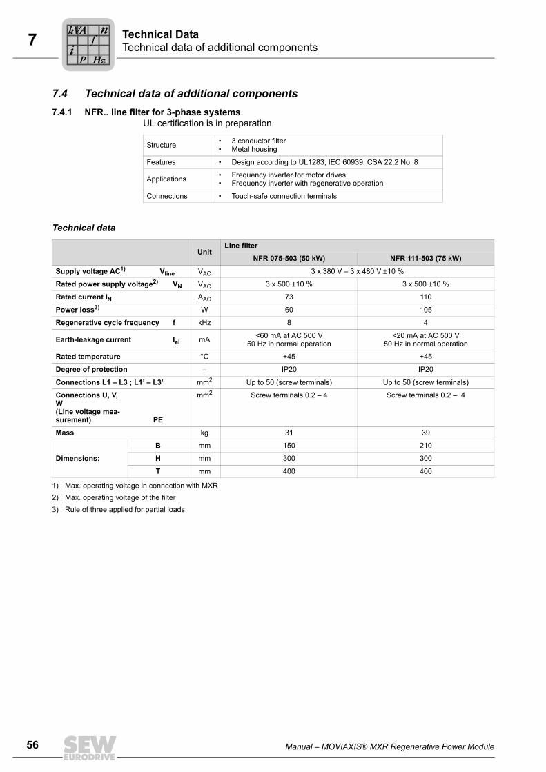
56 Manual – MOVIAXIS® MXR Regenerative Power Module
7 Technical data of additional components Technical Data
7.4 Technical data of additional components7.4.1 NFR.. line filter for 3-phase systems
UL certification is in preparation.
Technical data
Structure • 3 conductor filter• Metal housing
Features • Design according to UL1283, IEC 60939, CSA 22.2 No. 8
Applications • Frequency inverter for motor drives• Frequency inverter with regenerative operation
Connections • Touch-safe connection terminals
UnitLine filter
NFR 075-503 (50 kW) NFR 111-503 (75 kW)
Supply voltage AC1) Vline VAC 3 x 380 V – 3 x 480 V ±10 %
Rated power supply voltage2) VN VAC 3 x 500 ±10 % 3 x 500 ±10 %
Rated current IN AAC 73 110
Power loss3) W 60 105
Regenerative cycle frequency f kHz 8 4
Earth-leakage current Iel mA <60 mA at AC 500 V50 Hz in normal operation
<20 mA at AC 500 V50 Hz in normal operation
Rated temperature °C +45 +45
Degree of protection – IP20 IP20
Connections L1 – L3 ; L1’ – L3’ mm2 Up to 50 (screw terminals) Up to 50 (screw terminals)
Connections U, V, W(Line voltage mea-surement) PE
mm2 Screw terminals 0.2 – 4 Screw terminals 0.2 – 4
Mass kg 31 39
Dimensions:
B mm 150 210
H mm 300 300
T mm 400 400
1) Max. operating voltage in connection with MXR2) Max. operating voltage of the filter3) Rule of three applied for partial loads
Pi
fkVA
Hz
n
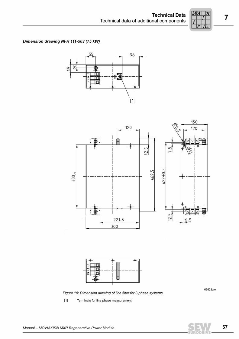
Manual – MOVIAXIS® MXR Regenerative Power Module 57
7 Technical data of additional componentsTechnical Data
Dimension drawing NFR 111-503 (75 kW)
63623axxFigure 15: Dimension drawing of line filter for 3-phase systems
[1] Terminals for line phase measurement
[1]
Pi
fkVA
Hz
n
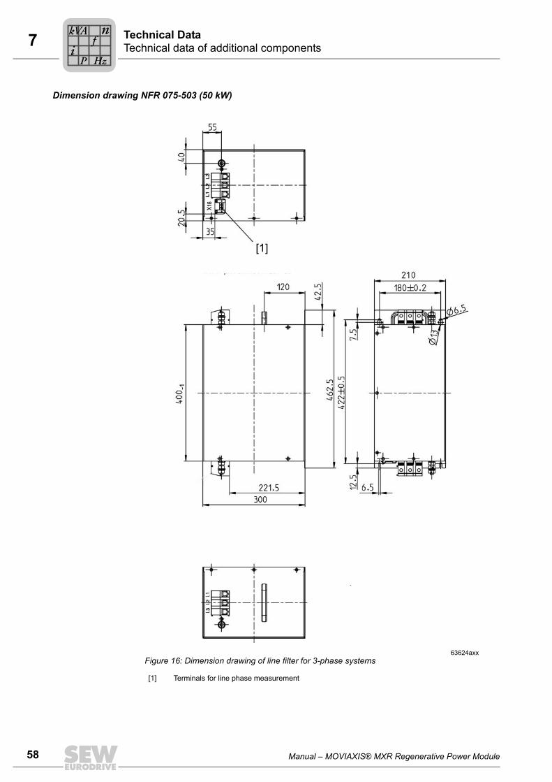
58 Manual – MOVIAXIS® MXR Regenerative Power Module
7 Technical data of additional components Technical Data
Dimension drawing NFR 075-503 (50 kW)
63624axxFigure 16: Dimension drawing of line filter for 3-phase systems
[1] Terminals for line phase measurement
[1]
Pi
fkVA
Hz
n

Manual – MOVIAXIS® MXR Regenerative Power Module 59
7 Technical data of additional componentsTechnical Data
7.4.2 NDR.. line choke
Wiring diagram
Technical data
62979AXXFigure 17: Wiring diagram of line choke
U1
V1
W1
U2
V2
W2
PE
Unit Line choke
NDR 075-083 (50 kW) NDR 110-063 (75 kW)
Supply voltage AC1) Vline
1) Max. operating voltage in connection with MXR
VAC 3 x 380 V – 3 x 480 V ±10 %
Rated power supply voltage2) VN
2) Max. operating voltage of the choke
VAC 3 x 500 V, 50 Hz 3 x 500 V, 50 Hz
Rated current IN A 75 110
Power loss at• 25% IN• 50% IN• 75% IN• 100% IN
W• 139• 165• 209• 270
• 187• 238• 322• 440
Rated temperature °C +45 +45
Inductance mH 3 x 0.8 3 x 0.55
Enclosures according to EN 60529 – IP00 IP00
Mass kg 40 47
Dimensions:
B mm 240 240
H mm 410 410
T mm 200 220
Pi
fkVA
Hz
n
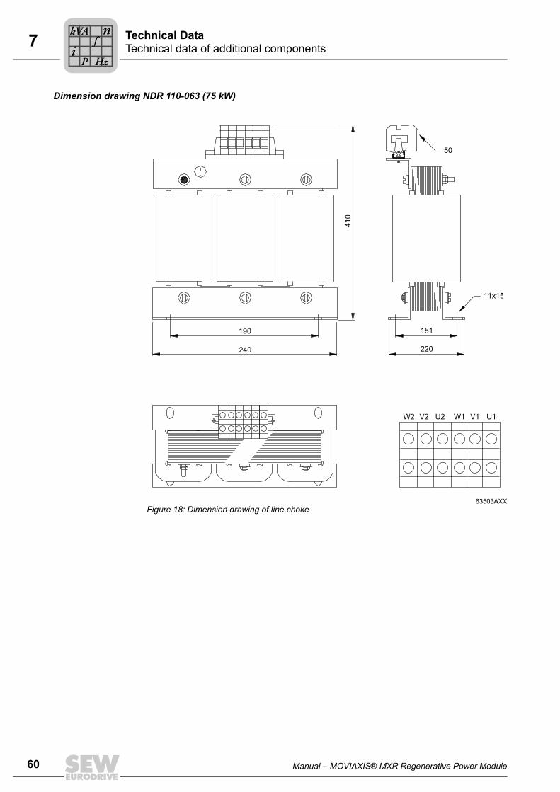
60 Manual – MOVIAXIS® MXR Regenerative Power Module
7 Technical data of additional components Technical Data
Dimension drawing NDR 110-063 (75 kW)
63503AXXFigure 18: Dimension drawing of line choke
190 151
220
W2 V2 U2 W1 V1 U1
50
11x15
410
240
Pi
fkVA
Hz
n

Manual – MOVIAXIS® MXR Regenerative Power Module 61
7 Technical data of additional componentsTechnical Data
Dimension drawing NDR 075-083 (50 kW)
62980AXXFigure 19: Dimension drawing of line choke
190 131
200
W2 V2 U2 W1 V1 U1
50
11x15
410
240
Pi
fkVA
Hz
n

62 Manual – MOVIAXIS® MXR Regenerative Power Module
8 General information Project Planning
8 Project Planning8.1 General information
Power levels of MXRThe MXR80A-075-503-00 regenerative power module has two power levels, 75 kW at4 kHz and 50 kW at 8 kHz, depending on the pulse width modulation (PWM 4 / 8 kHz)and the appropriate upstream units.
8.2 Components for EMC-compliant installationMOVIAXIS® servo inverters and supply modules are designed for use as componentsfor installation in machinery and systems. The components comply with the EMC prod-uct standard EN 61800-3 "Variable-speed electrical drives." Provided the information re-lating to EMC-compliant installation is observed, the devices satisfy the appropriate re-quirements for CE-marking of the entire machine/system in which they are fitted, on thebasis of the EMC Directive 2004/108/EC.
Interference immunity
With regard to interference immunity, MOVIAXIS® meets all the requirements stipulatedin EN 61000-6-2 and EN 61800-3.
Interference emission
Higher levels of interference are permitted in industrial environments than in residentialenvironments. In industrial environments, it may be possible to dispense with the mea-sures listed below depending on the situation of the supply system (grid) and the systemconfiguration.
Interference emission category
Compliance with category "C2" according to EN 61800-3 has been tested on a specifiedtest setup. SEW-EURODRIVE can provide detailed information on request.
NOTICEThe MXR regenerative power module may only be switched on when the drives arestanding still.
WARNING!This product can cause high-frequency interferences in residential areas which can re-quire measures for interference suppression.

Manual – MOVIAXIS® MXR Regenerative Power Module 63
8 Line contactor and line fusesProject Planning
8.3 Line contactor and line fusesLine contactor • Only use line contactors in utilization category AC-3 (IEC 158-1).
• The contactor K11 is designed for switching the MXR on and off only.
Line fuse types Line protection types in the operating classes gL, gG:• Rated fusing voltage ≥ Rated supply voltage
Line protection switches with characteristics B, C and D:• Line protection rated voltage ≥ rated supply voltage• Rated line protection switch currents must be 10 % above the rated regenerative
power module current.
8.4 Projecting the power supplyFor information about the permitted voltage systems, go to page 20.
The supply system requirements listed in the table below are informative extracts fromEN 61800-3.
NOTICE• Observe a minimum switch-off time of 10 s for the K11 contactor!• Do not switch the power on or off more than once per minute!• The line contactor must always be positioned before the line filter.
Power supply requirements 50 kW / 8 kHz 75 kW / 4 kHz
Minimal short circuit power of the supply system at the regenerative power module input1) 2)
1) Corresponds to Rsc > 67 and uk ≤ 1.5 %2) Input means the input of the NFR.. line filter, impedance of the supply cable must be taken into account.
> 3.4 MVA > 5.1 MVA
Permitted voltage distortion according to EN 61000-2-4, class 3 THD ≤ 10%
Power supply requirements Unit
Permitted frequency change Δf/t Hz/s ±1% x fline/1s
Permitted voltage asymmetry 3% of the negative-sequence component
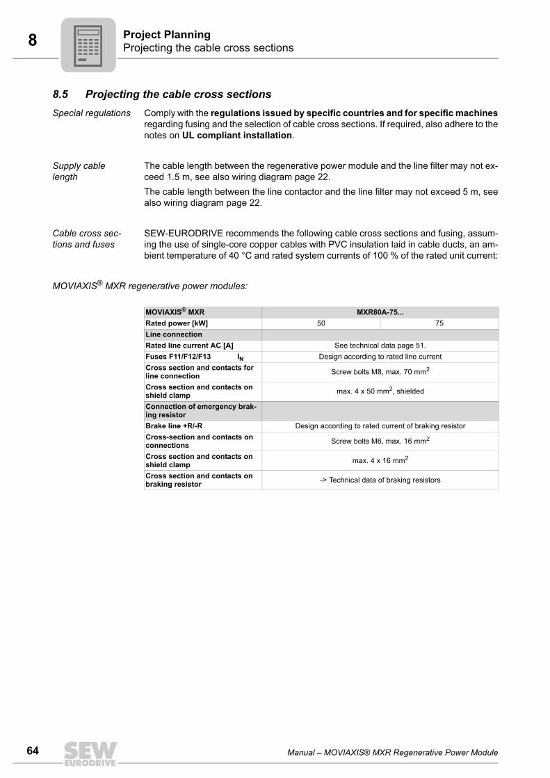
64 Manual – MOVIAXIS® MXR Regenerative Power Module
8 Projecting the cable cross sections Project Planning
8.5 Projecting the cable cross sectionsSpecial regulations Comply with the regulations issued by specific countries and for specific machines
regarding fusing and the selection of cable cross sections. If required, also adhere to thenotes on UL compliant installation.
Supply cable length
The cable length between the regenerative power module and the line filter may not ex-ceed 1.5 m, see also wiring diagram page 22. The cable length between the line contactor and the line filter may not exceed 5 m, seealso wiring diagram page 22.
Cable cross sec-tions and fuses
SEW-EURODRIVE recommends the following cable cross sections and fusing, assum-ing the use of single-core copper cables with PVC insulation laid in cable ducts, an am-bient temperature of 40 °C and rated system currents of 100 % of the rated unit current:
MOVIAXIS® MXR regenerative power modules:
MOVIAXIS® MXR MXR80A-75...Rated power [kW] 50 75Line connectionRated line current AC [A] See technical data page 51.Fuses F11/F12/F13 IN Design according to rated line currentCross section and contacts for line connection Screw bolts M8, max. 70 mm2
Cross section and contacts on shield clamp max. 4 x 50 mm2, shielded
Connection of emergency brak-ing resistor Brake line +R/-R Design according to rated current of braking resistorCross-section and contacts on connections Screw bolts M6, max. 16 mm2
Cross section and contacts on shield clamp max. 4 x 16 mm2
Cross section and contacts on braking resistor -> Technical data of braking resistors
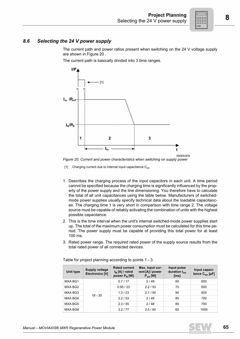
Manual – MOVIAXIS® MXR Regenerative Power Module 65
8 Selecting the 24 V power supplyProject Planning
8.6 Selecting the 24 V power supplyThe current path and power ratios present when switching on the 24 V voltage supplyare shown in Figure 20 .The current path is basically divided into 3 time ranges.
1. Describes the charging process of the input capacitors in each unit. A time periodcannot be specified because the charging time is significantly influenced by the prop-erty of the power supply and the line dimensioning. You therefore have to calculatethe total of all unit capacitances using the table below. Manufacturers of switched-mode power supplies usually specify technical data about the loadable capacitanc-es. The charging time 1 is very short in comparison with time range 2. The voltagesource must be capable of reliably activating the combination of units with the highestpossible capacitance.
2. This is the time interval when the unit's internal switched-mode power supplies startup. The total of the maximum power consumption must be calculated for this time pe-riod. The power supply must be capable of providing this total power for at least100 ms.
3. Rated power range. The required rated power of the supply source results from thetotal rated power of all connected devices.
Table for project planning according to points 1 - 3.
59085AENFigure 20: Current and power characteristics when switching on supply power
[1] Charging current due to internal input capacitance Con
Unit type Supply voltageElectronics [V]
Rated current IN [A] / rated
power PN [W]
Max. input cur-rent [A] / power
Pon [W]
Input pulse duration ton
[ms]
Input capaci-tance Con [µF]
MXA BG1
18 - 30
0.7 / 17 2 / 48 60 600
MXA BG2 0.95 / 23 2.2 / 53 70 600
MXA BG3 1.3 / 23 2.1 / 50 90 600
MXA BG4 2.2 / 53 2 / 48 80 700
MXA BG5 2.3 / 55 2 / 48 80 700
MXA BG6 3.2 / 77 2.5 / 60 60 1000
tin
≈≈
I /Pout
t
I/P
1 2 3
[1]
in
I /PNN
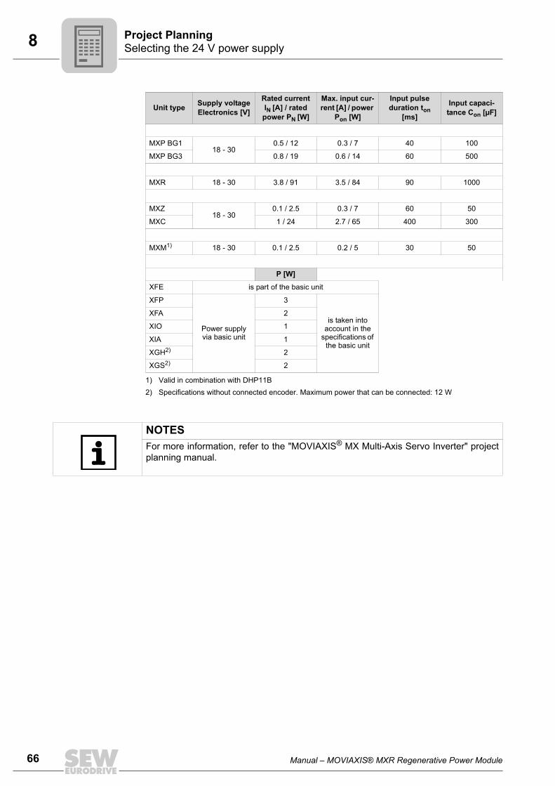
66 Manual – MOVIAXIS® MXR Regenerative Power Module
8 Selecting the 24 V power supply Project Planning
MXP BG118 - 30
0.5 / 12 0.3 / 7 40 100
MXP BG3 0.8 / 19 0.6 / 14 60 500
MXR 18 - 30 3.8 / 91 3.5 / 84 90 1000
MXZ18 - 30
0.1 / 2.5 0.3 / 7 60 50
MXC 1 / 24 2.7 / 65 400 300
MXM1) 18 - 30 0.1 / 2.5 0.2 / 5 30 50
P [W]
XFE is part of the basic unit
XFP
Power supply via basic unit
3
is taken into account in the
specifications of the basic unit
XFA 2
XIO 1
XIA 1
XGH2) 2
XGS2) 2
1) Valid in combination with DHP11B2) Specifications without connected encoder. Maximum power that can be connected: 12 W
Unit type Supply voltageElectronics [V]
Rated current IN [A] / rated
power PN [W]
Max. input cur-rent [A] / power
Pon [W]
Input pulse duration ton
[ms]
Input capaci-tance Con [µF]
NOTESFor more information, refer to the "MOVIAXIS® MX Multi-Axis Servo Inverter" projectplanning manual.
Manual – MOVIAXIS® MXR Regenerative Power Module 67
8 Projecting the emergency braking resistorProject Planning
8.7 Projecting the emergency braking resistor8.7.1 Notes on the emergency braking resistor
Without the supply voltage, motor operation of the drives is not possible and the DC linkcan absorb regenerative energy only to a limited extent. The operating states describedabove can therefore cause the drives to coast to a halt, or the motor brake to bring thedrive to a stop, if installed.To prevent an uncontrolled stop of the drives, an optional emergency braking resistorcan be connected to MOVIAXIS® MXR which brings the axes to a controlled stop in theevent of such an emergency. The kinetic energy in the drives is then dissipated via thebraking resistor as heat.
The following describes the procedure for projecting an emergency braking resistor forMOVIAXIS® MXR.
NOTESDas Under normal operating conditions, the MOVIAXIS® MXR regenerative powermodule feeds regenerative energy that exceeds the DC link buffer into the supply sys-tem. In practice, however, operating states can occur which prevent the MXR re-generative power module from feeding back energy into the supply system, e.g.in case of:• A power failure,• A failure of individual line phases (also momentary).
NOTICEUnder normal operating conditions, this optional braking resistor is not cyclically load-ed, but only in an emergency as described above. This braking resistor is therefore de-signed as emergency braking resistor.
DANGER!The supply cables to the emergency braking resistor carry a high DC voltage (aboutDC 970 V).Severe or fatal injuries from electric shock.• The emergency braking resistor cables must be suitable for this high DC voltage.• Install the emergency braking resistor cables according to the regulations.

68 Manual – MOVIAXIS® MXR Regenerative Power Module
8 Projecting the emergency braking resistor Project Planning
8.7.2 Selecting the emergency braking resistor
Selection criteria Selection of the emergency braking resistor is based on the following criteria:• Peak braking power• Thermal braking power
Peak braking power
The DC link voltage and the resistance value of the emergency braking resistor deter-mine the maximum braking power Pmax that can be dissipated from the DC link.The peak braking power is determined as follows:
VDC is the maximum DC link voltage, which is DC 970 V for MOVIAXIS®.The peak braking power Ppeak for each braking resistor is listed in the table of emergen-cy braking resistors on page 71
Determining the maximum emergency braking resistor power
Condition 1The maximum power of the emergency braking resistor Ppeak is larger than the maxi-mum regenerative power Pmax that is generated during emergency braking.
WARNING!The surfaces of the emergency braking resistors get very hot when the braking resis-tors are loaded with Prated.Risk of burns and fire.• Choose a suitable installation location. Emergency braking resistors are usually
mounted on top of the control cabinet.• Do not touch the emergency braking resistors.
NOTICE• The data in this section applies to BW... braking resistors when used as emergency
braking resistors.• The maximum permitted cable length between MOVIAXIS® and the emergency
braking resistor is 100 m.
60327AXXR
=U2
PmaxDC
63174AXX
Ppeak Max. power according to the table (→ page 71), which the emergency braking resistor can convert to heat.
Pmax Max. power that the emergency braking resistor has to dissipate from the DC link.
≥Ppeak Pmax

Manual – MOVIAXIS® MXR Regenerative Power Module 69
8 Projecting the emergency braking resistorProject Planning
Condition 2The previously determined amount of regenerative energy Wgeneratorisch is the basis forchecking whether the emergency braking resistor can dissipate this amount withoutthermal overload.
Thermal emergency braking powerThe thermal load on the emergency braking resistor must be taken into account whencarrying out project planning for the emergency braking resistor.The thermal load is calculated using the energy content of the emergency braking se-quence.This condition takes into account the heating of the emergency braking resistor over theentire emergency braking cycle.
• Calculating the maximum regenerative energy from the sum of the travel profiles ofall connected axes (taking into account the set emergency stop ramps and time se-quences).
Protection of the emergency braking resistor
63175AXX
Wmax Max. amount of energy that the emergency braking resistor can absorb
Wgeneratorisch Total amount of energy of the application regenerated during emergency braking.
≥Wmax Wgeneratorisch
NOTICEA thermal overload relay is necessary to protect the emergency braking resistor againstoverload. These relay types offer a setting option for the trip current. Set the trip currentto the rated current of the resistor (see page 71). No motor protection switches may be used.Important: Do not open the power contacts of the braking resistors in case of thermaloverload. The connection between braking resistor DC link may not be interrupted.Instead, the control contact of the overload relay opens relay K11 (see wiring diagramon page 21).
70 Manual – MOVIAXIS® MXR Regenerative Power Module
8 Projecting the emergency braking resistor Project Planning
Unit temperature
Operation of the regenerative power module in case of line faults
WARNING!The surfaces of the emergency braking resistors get very hot when the braking resis-tors are loaded with Prated.Risk of burns and fire.• Choose a suitable installation location. Emergency braking resistors are usually
mounted on top of the control cabinet.• Do not touch the emergency braking resistors.
TIPSEmergency braking resistors can become very hot during operation. The high temper-atures can heat up the cage of the emergency braking resistor to over 100 °C. This means that the ventilation, size of the installation site and distance to componentsand parts at risk must be provided accordingly. The emergency braking resistor usually delivers its rated power for an extended periodof time.
NOTICELine faults, e.g. power failures, can cause the brake chopper to respond and load thebraking resistor. This happens if the DC link cannot buffer any more regenerative en-ergy. The mean utilization of the connected resistor can be exceeded, which will triggerthe bimetallic protective relay (protection of the braking resistor).The line quality can be a reason for this, for example. The line quality influences projectplanning for the braking resistor, especially if the resistor is designed as an emergencybraking resistor.If the braking resistor is designed as an emergency braking resistor, this means that,depending on the amount of regenerative energy • The trip contact of the bimetallic protective relay trips in normal operation,• Due to this load, the emergency braking resistor is no longer capable of dissipating
the regenerative energy in the event of an actual emergency. In this case, the bime-tallic protective relay trips.
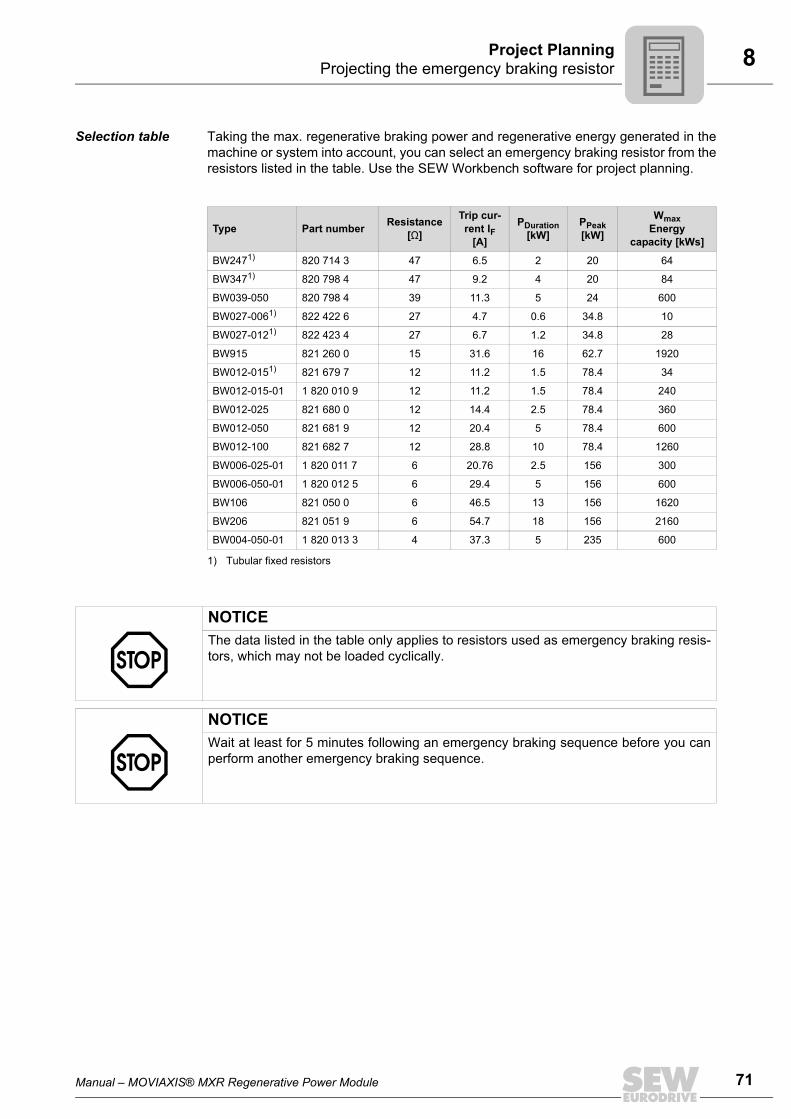
Manual – MOVIAXIS® MXR Regenerative Power Module 71
8 Projecting the emergency braking resistorProject Planning
Selection table Taking the max. regenerative braking power and regenerative energy generated in themachine or system into account, you can select an emergency braking resistor from theresistors listed in the table. Use the SEW Workbench software for project planning.
Type Part number Resistance [Ω]
Trip cur-rent IF
[A]
PDuration [kW]
PPeak [kW]
WmaxEnergy
capacity [kWs]
BW2471)
1) Tubular fixed resistors
820 714 3 47 6.5 2 20 64
BW3471) 820 798 4 47 9.2 4 20 84
BW039-050 820 798 4 39 11.3 5 24 600
BW027-0061) 822 422 6 27 4.7 0.6 34.8 10
BW027-0121) 822 423 4 27 6.7 1.2 34.8 28
BW915 821 260 0 15 31.6 16 62.7 1920
BW012-0151) 821 679 7 12 11.2 1.5 78.4 34
BW012-015-01 1 820 010 9 12 11.2 1.5 78.4 240
BW012-025 821 680 0 12 14.4 2.5 78.4 360
BW012-050 821 681 9 12 20.4 5 78.4 600
BW012-100 821 682 7 12 28.8 10 78.4 1260
BW006-025-01 1 820 011 7 6 20.76 2.5 156 300
BW006-050-01 1 820 012 5 6 29.4 5 156 600
BW106 821 050 0 6 46.5 13 156 1620
BW206 821 051 9 6 54.7 18 156 2160
BW004-050-01 1 820 013 3 4 37.3 5 235 600
NOTICEThe data listed in the table only applies to resistors used as emergency braking resis-tors, which may not be loaded cyclically.
NOTICEWait at least for 5 minutes following an emergency braking sequence before you canperform another emergency braking sequence.
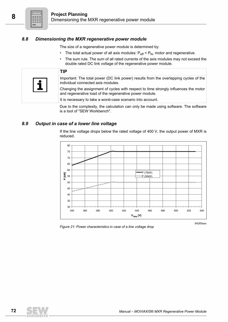
72 Manual – MOVIAXIS® MXR Regenerative Power Module
8 Dimensioning the MXR regenerative power module Project Planning
8.8 Dimensioning the MXR regenerative power moduleThe size of a regenerative power module is determined by:• The total actual power of all axis modules: Peff < PN, motor and regenerative.• The sum rule. The sum of all rated currents of the axis modules may not exceed the
double rated DC link voltage of the regenerative power module.
Due to the complexity, the calculation can only be made using software. The softwareis a tool of "SEW Workbench".
8.9 Output in case of a lower line voltageIf the line voltage drops below the rated voltage of 400 V, the output power of MXR isreduced.
TIPImportant: The total power (DC link power) results from the overlapping cycles of theindividual connected axis modules. Changing the assignment of cycles with respect to time strongly influences the motorand regenerative load of the regenerative power module. It is necessary to take a worst-case scenario into account.
64265axxFigure 21: Power characteristics in case of a line voltage drop
30
35
40
45
50
55
60
65
70
75
80
340 360 380 400 420 440 460 480 500 520 540
U [V]
P [
kW
] P (75kW)
P (50kW)
Netz

Manual – MOVIAXIS® MXR Regenerative Power Module 73
8 Overload capacityProject Planning
8.10 Overload capacityThe overload requirement of the application is based on the projected axis modules.You must check• The required output power,• The ramp time,
In case of ramp times shorter than the values in the table below, a braking resistor ismandatory.
• The braking resistor.SEW-EURODRIVE recommends the following braking resistors:
Overload data in % must be applied to the rated unit power at the respective line voltage,see chapter "Output in case of lower line voltage", page 72.
Sample power curve of a MXR 50 kW at 160 % overload.
MXR 50 kW MXR 75 kW
BW012-015 BW006-025-01
Power rating Voltage [V] Overload [%] Ramp time [ms]
MXR 50 kW360 – 380 160 20
380 – 480 200 20
MXR 75 kW360 – 380 110 200
380 – 480 200 100
t
P
motor
regenerative
80 kW
80 kW
ramp time
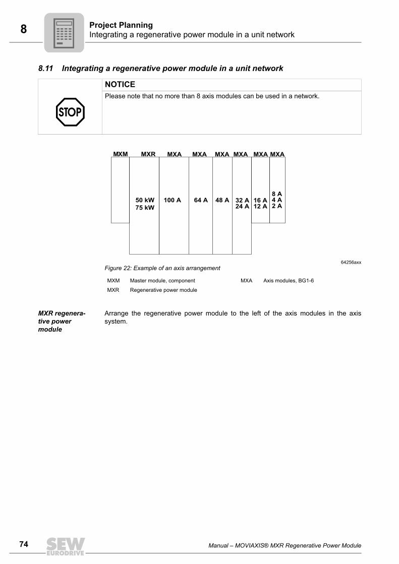
74 Manual – MOVIAXIS® MXR Regenerative Power Module
8 Integrating a regenerative power module in a unit network Project Planning
8.11 Integrating a regenerative power module in a unit network
MXR regenera-tive power module
Arrange the regenerative power module to the left of the axis modules in the axissystem.
NOTICEPlease note that no more than 8 axis modules can be used in a network.
64256axxFigure 22: Example of an axis arrangement
MXM Master module, component MXA Axis modules, BG1-6
MXR Regenerative power module
100 A
MXR MXA MXA MXA MXA MXA MXA
64 A 48 A 32 A24 A
16 A12 A
8 A4 A2 A
50 kW
75 kW
MXM
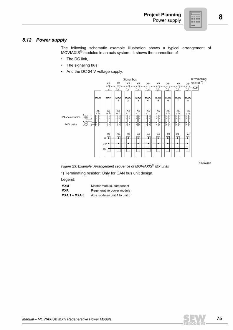
Manual – MOVIAXIS® MXR Regenerative Power Module 75
8 Power supplyProject Planning
8.12 Power supplyThe following schematic example illustration shows a typical arrangement ofMOVIAXIS® modules in an axis system. It shows the connection of• The DC link,• The signaling bus• And the DC 24 V voltage supply.
*) Terminating resistor: Only for CAN bus unit design.Legend:
64257aenFigure 23: Example: Arrangement sequence of MOVIAXIS® MX units
MXM Master module, componentMXR Regenerative power moduleMXA 1 – MXA 8 Axis modules unit 1 to unit 8
X4 X4 X4 X4 X4 X4 X4 X4 X4
X9a / b
PE
UZ+
UZ-
24 V electronics
MXR
aX5
b AM2aX5
b AM3aX5
b AM4aX5
b
MXA1
MXA2
MXA3
MXA4
MXA5
MXA6
MXA7
MXA8
aX5
b AM6aX5
b AM7aX5
b AM8aX5
bAM5aX5
b
24 V brake
X9a / b
X9a / b
X9a / b
X9a / b
X9a / b
X9a / b
X9a / b
X9a / b
Signal bus Terminatingresistor
MXM
aX5
b
)*
+
–
+
–
76 Manual – MOVIAXIS® MXR Regenerative Power Module
Index
9 Index
Numerics24 V power supply, selection ......................... 65
AAccessories.................................................... 14Accessory assignment table .......................... 15Additional components................................... 56
BBraking resistors
Operation ................................................. 20Bus communication........................................ 53
CCable cross section........................................ 19Cable cross sections and fuses ..................... 64CAN system bus ............................................ 27Combining MXR with other units.................... 13Connection
Electrical .................................................... 9Connection of emergency braking resistor..... 19Connection of MXR regenerative power module................................................. 21Control electronics, wiring .............................. 21
DDesignated use ................................................ 7Dimension sheet of MXR ............................... 54Drilling template of MXR ................................ 55
EElectrical connection ........................................ 9Electrical installation....................................... 18Electromagnetic compatibility
Interference emission .............................. 62Interference emission categories............. 62Interference immunity .............................. 62
Emergency braking resistor ........................... 67Connection .............................................. 19
Emergency braking resistor, notes................. 67Error table ...................................................... 45EtherCAT
Fieldbus ................................................... 30System bus .............................................. 29
Exclusion of liability .......................................... 6
FFieldbus
EtherCAT ................................................. 30
IInstallation ........................................................ 8
Electrical .................................................. 18Mechanical............................................... 16
Installation of regenerative power module ..... 18Integrating a regenerative power module in a unit network ................................ 74
LLine choke NDR.. ........................................... 59Line contactor................................................. 19Line filter for 3-phase system ......................... 56Line fuses, fuse types .................................... 63
MMeasuring cable X18 of the line filter ............. 19Mechanical installation ................................... 16
NNameplate...................................................... 10Notes on the emergency braking resistor....... 67Notes on the wiring diagrams......................... 21
OOperating displays ......................................... 44Operating displays and errors of MXR ........... 44Operation ....................................................... 43Operation of emergency braking resistor ....... 20Other applicable documentation ...................... 5
PParameter description .................................... 39Permitted tightening torque
DC link connection ................................... 16Permitted tightening torques .......................... 16
Power terminals ....................................... 16Signal terminals ....................................... 16
Permitted voltage supply systems.................. 20Power connections, wiring ............................. 22Process data assignment for fieldbus operation........................................... 33Project planning
Notes on the emergency braking resistor ........................................ 67
Project planning for MXRDimensioning MXR .................................. 72EMC-compliant installation ...................... 62Emergency braking resistor ..................... 67Integrating a regenerative power module in a unit network .......................... 74Line contactor and line fuses ................... 63
Maximum emergency braking resistor power .......................................... 68
Manual – MOVIAXIS® MXR Regenerative Power Module 77
Index
Operation of MXR in case of line faults ... 70Output in case of lower line voltage......... 72Overload capacity .................................... 73Peak braking power ................................. 68Power supply ........................................... 75Projecting the cable cross sections ......... 64Projecting the power supply .................... 63Protection of the braking resistor ............. 69Selecting the 24 V power supply ............. 65Selection table of emergency braking resistors ...................................... 71Thermal emergency braking power ......... 69Unit temperature ...................................... 70
Project planning of MXR ................................ 62Putting into storage .......................................... 8
RReference potentials - Notes.......................... 23Reference potentials inside the unit - Notes .. 23Removal of regenerative power module ........ 18Rights to claim under limited warranty ............. 6
SSafe disconnection........................................... 9Safety notes ..................................................... 7
Designated use.......................................... 7Electrical connection.................................. 9General ...................................................... 7Installation ................................................. 8Operation ................................................... 9Safe disconnection .................................... 9Safety functions ......................................... 8Shipping..................................................... 8Structure .................................................... 5Target group .............................................. 7
Standard accessories..................................... 14Startup ........................................................... 26
Prerequisite ............................................. 26Startup of MXR............................................... 36Supply cable length........................................ 64Switch-on sequence MXR.............................. 31Switch-on sequence of MXR
Addendum to the diagram ....................... 32System bus
CAN ......................................................... 27EtherCAT ................................................. 29
TTechnical data
Bus communication ................................. 53Control section......................................... 52General .................................................... 50Power section .......................................... 51
Terminal assignment...................................... 23Terminal assignment of MXR......................... 24
UUL-compliant installation ................................ 16Unit design ..................................................... 10Unit design of MXR ........................................ 12Unit designation ............................................. 11Unit installation................................................. 8
VVoltage supply systems, permitted ................ 20
WWiring
Control electronics ................................... 21Power connections .................................. 22
Wiring diagrams ............................................. 21


SEW-EURODRIVE – Driving the world

How we’re driving the world
With people whothink fast anddevelop thefuture with you.
With a worldwide service network that isalways close at hand.
With drives and controlsthat automaticallyimprove your productivity.
With comprehensiveknowledge in virtuallyevery branch ofindustry today.
With uncompromisingquality that reduces thecost and complexity ofdaily operations.
With a global presencethat offers responsive and reliable solutions. Anywhere.
With innovativetechnology that solvestomorrow’s problemstoday.
With online informationand software updates,via the Internet, availablearound the clock.
Drive Technology \ Drive Automation \ System Integration \ Services
SEW-EURODRIVEDriving the world
www.sew-eurodrive.com
SEW-EURODRIVE GmbH & Co KGP.O. Box 3023 · D-76642 Bruchsal / GermanyPhone +49 7251 75-0 · Fax +49 7251 [email protected]


![MXR PHASE 90 - stewmac.com MXR Phase 90 Script Mod … · [ 1] Black and white pushback wire [2] 1/8" heat shrink - 2" length [ 1] Mini toggle switch [ 1] MXR Phase 90 Script Mod](https://img.pdfslide.net/doc/110x75/5edc85adad6a402d6667372d/mxr-phase-90-mxr-phase-90-script-mod-1-black-and-white-pushback-wire-2.jpg)