Embed Size (px)
Citation preview
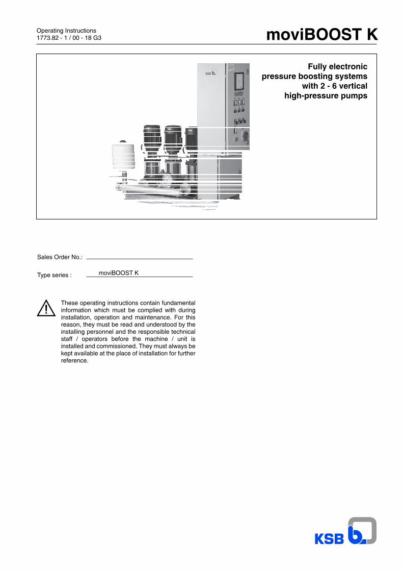
moviBOOST K
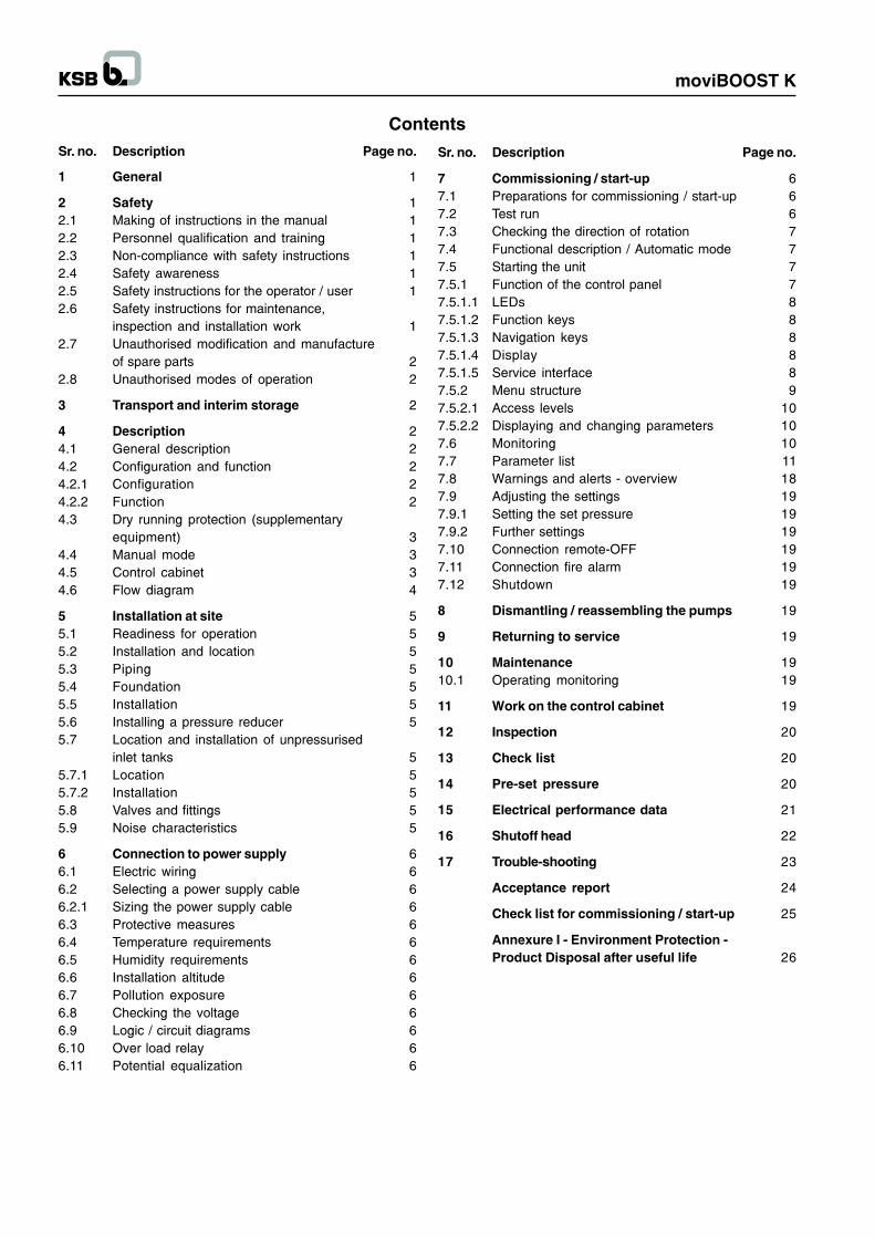
Sr. no. Description Page no.
1 General 1
2 Safety 12.1 Making of instructions in the manual 12.2 Personnel qualification and training 12.3 Non-compliance with safety instructions 12.4 Safety awareness 12.5 Safety instructions for the operator / user 12.6 Safety instructions for maintenance,
inspection and installation work 12.7 Unauthorised modification and manufacture
of spare parts 22.8 Unauthorised modes of operation 2
3 Transport and interim storage 2
4 Description 24.1 General description 24.2 Configuration and function 24.2.1 Configuration 24.2.2 Function 24.3 Dry running protection (supplementary
equipment) 34.4 Manual mode 34.5 Control cabinet 34.6 Flow diagram 4
5 Installation at site 55.1 Readiness for operation 55.2 Installation and location 55.3 Piping 55.4 Foundation 55.5 Installation 55.6 Installing a pressure reducer 55.7 Location and installation of unpressurised
inlet tanks 55.7.1 Location 55.7.2 Installation 55.8 Valves and fittings 55.9 Noise characteristics 5
6 Connection to power supply 66.1 Electric wiring 66.2 Selecting a power supply cable 66.2.1 Sizing the power supply cable 66.3 Protective measures 66.4 Temperature requirements 66.5 Humidity requirements 66.6 Installation altitude 66.7 Pollution exposure 66.8 Checking the voltage 66.9 Logic / circuit diagrams 66.10 Over load relay 66.11 Potential equalization 6
Contents
Sr. no. Description Page no.
7 Commissioning / start-up 67.1 Preparations for commissioning / start-up 67.2 Test run 67.3 Checking the direction of rotation 77.4 Functional description / Automatic mode 77.5 Starting the unit 77.5.1 Function of the control panel 77.5.1.1 LEDs 87.5.1.2 Function keys 87.5.1.3 Navigation keys 87.5.1.4 Display 87.5.1.5 Service interface 87.5.2 Menu structure 97.5.2.1 Access levels 107.5.2.2 Displaying and changing parameters 107.6 Monitoring 107.7 Parameter list 117.8 Warnings and alerts - overview 187.9 Adjusting the settings 197.9.1 Setting the set pressure 197.9.2 Further settings 197.10 Connection remote-OFF 197.11 Connection fire alarm 197.12 Shutdown 19
8 Dismantling / reassembling the pumps 19
9 Returning to service 19
10 Maintenance 1910.1 Operating monitoring 19
11 Work on the control cabinet 19
12 Inspection 20
13 Check list 20
14 Pre-set pressure 20
15 Electrical performance data 21
16 Shutoff head 22
17 Trouble-shooting 23
Acceptance report 24
Check list for commissioning / start-up 25
Annexure I - Environment Protection -Product Disposal after useful life 26
moviBOOST K
1. GeneralThese operating instructions are intended to facilitatefamiliarization with the unit and its designated use.
The manual contains important information for reliable, properand efficient operation. Compliance with the operatinginstructions is of vital importance to ensure reliability and along service life of the unit and to avoid any risks.
These operating instructions do not take into account localregulations; the operator must ensure that such regulationsare strictly observed by all, including the personnel called infor installation.
This pump / unit must not be operated beyond the limit valuesfor the fluid handled, capacity, speed, density, pressure,temperature and motor rating specified in the technicaldocumentation. Make sure that operation is in accordancewith the instructions laid down in this manual or in the contractdocumentation.
The name plate indicates the type series / size, main operatingdata and works / serial number; please quote this informationin all queries, repeat orders and particularly when orderingspare parts.
If you need additional information or instructions or if the deviceis damaged, contact your nearest KSB customer service centre.
2. SafetyThese operating instructions contain important informationwhich must be observed when installing, operating andmaintaining the unit. Therefore this operating manual must beread and understood both by the installing personnel and theresponsible trained personnel / operators prior to installationand commissioning, and it must always be kept close to thelocation of operation of the machine / unit for easy access.
Not only must the general safety instructions laid down in thischapter on �Safety� be complied with, but also the safetyinstructions outlines under specific headings.
2.1 Marking of instructions in the manual
The safety instructions contained in this manual whose non-observance might cause hazards to persons are speciallymarked with the general hazard sign, namely
general hazard sign to ISO 7000 - 0434The electrical danger warning sign is
safety sign to IEC 417 - 5036,
The word
is used to introduce safety instructions whose non-observancemay lead to damage to the equipment and its functions.
1
Instructions attached directly to the machine, e.g.- arrow indicating the direction of rotation- markings for fluid connectionsmust always be complied with and be kept in a perfectly legiblecondition at all times.
2.2 Personnel qualification and training
All personnel involved in the operation, maintenance,inspection and installation of the unit must be fully qualified tocarry out the work involved. Personnel responsibilities,competence and supervision must be clearly defined by theoperator. If the personnel in question does not alreadypossess the requisite know-how, appropriate training andinstruction must be provided. If required, the operator maycommission the manufacturer / supplier to take care of suchtraining. In addition, the operator is responsible for ensuringthat the contents of the operating instructions are fullyunderstood by the responsible personnel.
2.3 Non-compliance with safety instructions
Non-compliance with safety instructions can jeopardize thesafety of personnel, the environment and the machine / unititself. Non-compliance with these safety instructions will alsolead to forfeiture of any and all rights to claims for damages.
In particular, non-compliance can, for example, result in :
- failure of important machine / system functions,
- failure of prescribed maintenance and servicing practices,
- hazard to persons by electrical, mechanical and chemicaleffects,
- hazard to the environment due to leakage of hazardoussubstances.
2.4 Safety awareness
It is imperative to comply with the safety instructions containedin this manual, the relevant national health and safetyregulations and the operator�s own internal work, operationand safety regulations.
2.5 Safety instructions for the operator / user
- Any hot or cold components that could pose ahazard must be equipped with a guard by theoperator.
- Guards which are fitted to prevent accidentalcontact with moving parts (e.g. coupling) must notbe removed whilst the unit is operating.
- Leakages (e.g. at the shaft seal) of hazardous fluidshandled (e.g. explosive, toxic, hot) must becontained so as to avoid any danger to personsand the environment. All relevant laws must beheeded.
- Electrical hazards must be eliminated. (In thisrespect refer to the relevant safety regulationsapplicable to different countries and / or the localenergy supply companies.)
2.6 Safety instructions for maintenance,inspection and installation work
The operator is responsible for ensuring that all maintenance,inspection and installation work be performed by authorised,qualified specialist personnel who are thoroughly familiar withthe manual.
moviBOOST K
2
Work on the machine / unit must be carried out only duringstandstill. The shutdown procedure described in the manualfor taking the unit out of service must be adhered to withoutfail.
Pumps or pump units handling fluids injurious to health mustbe decontaminated.
Immediately following completion of the work, all safety-relevant and protective devices must be re-installed and / orre-activated.
Please observe all instructions set out in the chapter on�Commissioning / start-up� before returning the unit to service.
2.7 Unauthorised modification and manufactureof spare parts
Modifications or alterations of the equipment supplied are onlypermitted after consultation with the manufacturer. Originalspare parts and accessories authorised by the manufacturerensure safety. The use of other parts can invalidate any liabilityof the manufacturer for resulting damage.
2.8 Unauthorised modes of operation
The warranty relating to the operating reliability and safety ofthe unit supplied is only valid if the equipment is used inaccordance with its designated use (see section 4). The limitsstated in the data sheet must not be exceeded under anycircumstances.
3 Transport and interim storageThe package unit is packaged on pallets or in wooden cratesand wrapped in plastic foil for shipping and interim storage.All connecting points are capped. It is imperative that theshipping / handling instructions shown on the package befollowed.
The unit must be protected against frost.
If upon unpackaging the unit you should discover that thepackage has been damaged by dropping or some other formof mechanical impact, please carefully inspect the unit itselffor possible damage and inform the freight forwarder / KSB�scustomer service, even if you have not been able to detectany such damage.
Once the unit has been removed from the package, it must bestored in accordance with the location and installationinstructions (see Installation and location).
4 Description
4.1 General description
The fully electronic pressure boosting package units aresupplied ready for connection.
The equipment circuitry allows both direct and indirectconnection to the water supply system.
The equipment must be operated and maintained as toensure uninterrupted reliability of water supply, withoutcausing disturbances in the public water supply or otherconsumer supply systems.
Any applicable Water utility or fire protection regulationsmust be complied with.
Furthermore, local conditions must be taken into account (forexample excessive or very unsteady supply pressure requiringthe installation of a pressure reducer).
4.2 Configuration and function
4.2.1 Configuration
Between 2 and 6 vertical high-pressure pumps (for descriptionand function, please refer to the pump�s Operating Instruction)are arranged on a baseplate.
Each pump is installed on its own anti-vibration mounts.
Pumps connected in line are coupled by mild steel pipes.
On the system side, a swing check valve and a shut-off butterflyvalve are fitted downstream of each pump.
On the suction side, a ball valve or a shut-off butterfly valveare fitted upstream of each pump as a service valve.
The shut-off elements permit dismantling of individual pumpswithout having to drain the pipework. The discharge side non-return valve ensures that the system remains filled with waterand prevents backflow through the pumps.
Both distributor pipes feature additional connections fordraining, venting and installation of various dry runningprotection devices.
The surge vessel (accumulator) is fitted with an isolating valve.It compensates discharge-side peak pressures and togetherwith the minimum operating period, limits the pumps� switchingfrequency.
moviBOOST K units are switched on as a function of pressure.To this effect, a pressure transmitter is fitted in the discharge-side piping.
Depending on the number and performance of the pumps,the completely wired control cabinet is either suppliedmounted on the baseplate or as a free-standing cabinet.
Only additional and special equipment is already fitted on thesystem.
Accessories such as expansion joints, tanks, accumulators,pressure reducers etc. are supplied with the unit but are notmounted.
The unit is driven by surface-cooled three-phase squirrel-cagemotors, 50 Hz, air-cooled, 2-pole, KSB standardised motorwith main dimensions to IEC. Other motor makes afterconsultation with KSB.
up to 2.2 kW 220-240 V/380-420 V,from 3 kW 380-420 V/660-725 Venclosure IP 55, thermal class F, up to 4 kW design V18,from 5.5 kW design V1
4.2.2 Function
The moviBOOST unit is switched on and off as a function ofthe pressure. The start-up pressure pE and the switch-offpressure pA are derived from the adjustable set value psolland the adjustable hysteresis.
pE = psoll - hysteresis, pA = psoll + hysteresis.
Automatic mode
The unit consisting of 2 to 6 pumps starts the first pump whenthe pressure falls below the start-up pressure pE.
moviBOOST K
When the start-up pressure is reached, a minimum operatingperiod of 3 minutes is activated.
If this pump meets the current demand and if a pressure > pEand < pA is maintained, the pump operates until the demanddrops and the switch-off pressure pA is reached.
If the first pump cannot meet the demand, the pressure will fallbelow pE again, and the next pump available is started after acut-in delay period of 2 seconds.
This routine is repeated until all pumps are running.
If the unit has been correctly selected the demand will becovered without using the stand-by pump.
As demand decreases, the pumps are automaticallysequenced out after their minimum operating period and acut-out delay of 2 seconds. The pump that was started up firstwill be switched off first.
In order to ensure equal distribution of pump operating hours,the pumps will be changed for the next start-up cycle.
The operating status is displayed via LEDs.
4.3 Dry running protection (supplementaryequipment)
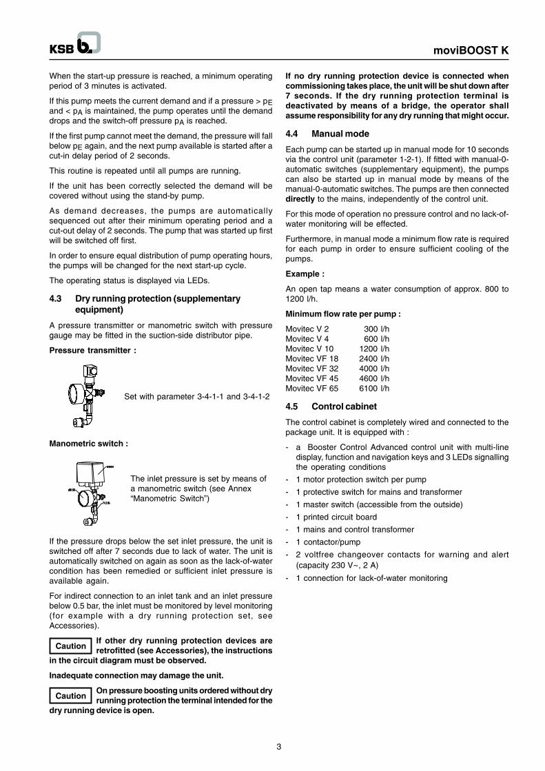
A pressure transmitter or manometric switch with pressuregauge may be fitted in the suction-side distributor pipe.
Pressure transmitter :
Set with parameter 3-4-1-1 and 3-4-1-2
Manometric switch :
The inlet pressure is set by means ofa manometric switch (see Annex�Manometric Switch�)
If the pressure drops below the set inlet pressure, the unit isswitched off after 7 seconds due to lack of water. The unit isautomatically switched on again as soon as the lack-of-watercondition has been remedied or sufficient inlet pressure isavailable again.
For indirect connection to an inlet tank and an inlet pressurebelow 0.5 bar, the inlet must be monitored by level monitoring(for example with a dry running protection set, seeAccessories).
If other dry running protection devices areretrofitted (see Accessories), the instructions
in the circuit diagram must be observed.
Inadequate connection may damage the unit.
On pressure boosting units ordered without dryrunning protection the terminal intended for the
dry running device is open.
If no dry running protection device is connected whencommissioning takes place, the unit will be shut down after7 seconds. If the dry running protection terminal isdeactivated by means of a bridge, the operator shallassume responsibility for any dry running that might occur.
4.4 Manual mode
Each pump can be started up in manual mode for 10 secondsvia the control unit (parameter 1-2-1). If fitted with manual-0-automatic switches (supplementary equipment), the pumpscan also be started up in manual mode by means of themanual-0-automatic switches. The pumps are then connecteddirectly to the mains, independently of the control unit.
For this mode of operation no pressure control and no lack-of-water monitoring will be effected.
Furthermore, in manual mode a minimum flow rate is requiredfor each pump in order to ensure sufficient cooling of thepumps.
Example :
An open tap means a water consumption of approx. 800 to1200 l/h.
Minimum flow rate per pump :
Movitec V 2 300 l/hMovitec V 4 600 l/hMovitec V 10 1200 l/hMovitec VF 18 2400 l/hMovitec VF 32 4000 l/hMovitec VF 45 4600 l/hMovitec VF 65 6100 l/h
4.5 Control cabinet
The control cabinet is completely wired and connected to thepackage unit. It is equipped with :
- a Booster Control Advanced control unit with multi-linedisplay, function and navigation keys and 3 LEDs signallingthe operating conditions
- 1 motor protection switch per pump
- 1 protective switch for mains and transformer
- 1 master switch (accessible from the outside)
- 1 printed circuit board
- 1 mains and control transformer
- 1 contactor/pump
- 2 voltfree changeover contacts for warning and alert(capacity 230 V~, 2 A)
- 1 connection for lack-of-water monitoring
3
moviBOOST K
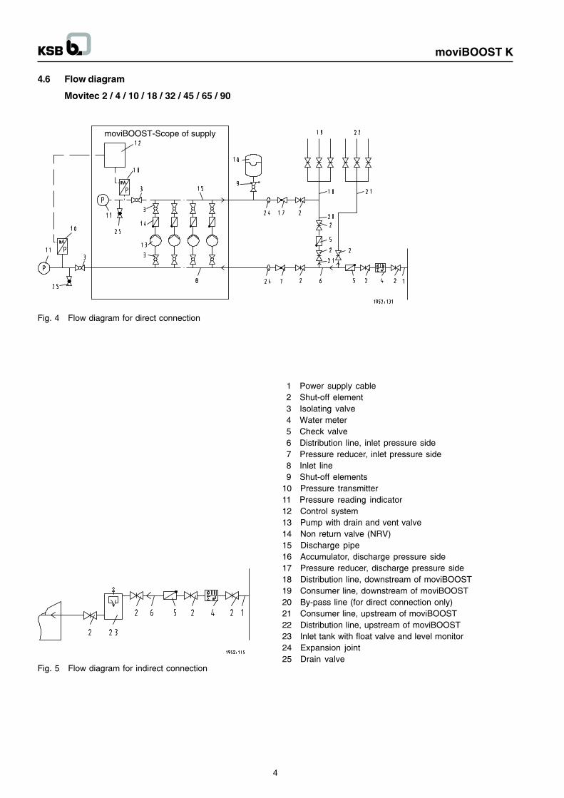
4.6 Flow diagram
Movitec 2 / 4 / 10 / 18 / 32 / 45 / 65 / 90
Fig. 4 Flow diagram for direct connection
Fig. 5 Flow diagram for indirect connection
1 Power supply cable2 Shut-off element3 Isolating valve4 Water meter5 Check valve6 Distribution line, inlet pressure side7 Pressure reducer, inlet pressure side8 Inlet line9 Shut-off elements
10 Pressure transmitter11 Pressure reading indicator12 Control system13 Pump with drain and vent valve14 Non return valve (NRV)15 Discharge pipe16 Accumulator, discharge pressure side17 Pressure reducer, discharge pressure side18 Distribution line, downstream of moviBOOST19 Consumer line, downstream of moviBOOST20 By-pass line (for direct connection only)21 Consumer line, upstream of moviBOOST22 Distribution line, upstream of moviBOOST23 Inlet tank with float valve and level monitor24 Expansion joint25 Drain valve
4
moviBOOST K
5 Installation at site
5.1 Readiness for operation
The owner or the owner�s representative must report thepackage system�s readiness for operation to the responsibleauthorities (normally either the water company or the TradeInspection Office). Prior to commissioning, the operator mustdemonstrate conclusively that the installation requirementshave been complied with.
The power supply line must be installed / connected by a dulyauthorised company.
5.2 Installation and location
The moviBOOST must be located either in the control room orin a well-ventilated, frost-free, lockable room used for no otherpurpose. No harmful gases are allowed to enter the place ofinstallation. An adequately sized drain connection (leading toa sewer or equivalent) must be provided.
The unit is designed for a maximum ambient temperature of00C to +400C at a relative air humidity of 50%.
For pressure vessel (accumulator) installation, please refer tothe Operating Instructions in the Annex.
moviBOOST units should not be installed next to sleeping orliving quarters.
Thanks to the anti-vibration mounting buffers, themoviBOOST K unit is adequately insulated to preventtransmission of solid-borne noise.
5.3 Piping
All piping must be installed without transmitting any stressesor strains. The use of length-limited expansion joints isadvisable (see Accessories).
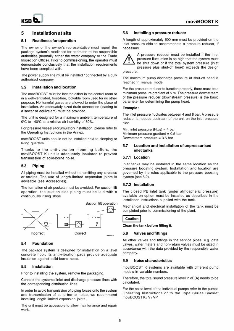
The formation of air pockets must be avoided. For suction liftoperation, the suction side piping must be laid with acontinuously rising slope.
5.4 Foundation
The package system is designed for installation on a levelconcrete floor. Its anti-vibration pads provide adequateinsulation against solid-borne noise.
5.5 Installation
Prior to installing the system, remove the packaging.
Connect the system�s inlet and discharge pressure lines withthe corresponding distribution lines.
In order to avoid transmission of piping forces onto the systemand transmission of solid-borne noise, we recommendinstalling length-limited expansion joints.
The unit must be accessible to allow maintenance and repairwork.
5.6 Installing a pressure reducer
A length of approximately 600 mm must be provided on theinlet pressure side to accommodate a pressure reducer, ifnecessary.
A pressure reducer must be installed if the inletpressure fluctuation is so high that the system mustbe shut down or if the total system pressure (inletpressure plus shut-off head) exceeds the design
pressure.
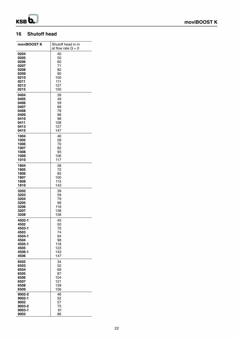
The maximum pump discharge pressure at shut-off head isreached in manual mode.
For the pressure reducer to function properly, there must be aminimum pressure gradient of 5 m. The pressure downstreamof the pressure reducer (downstream pressure) is the basicparameter for determining the pump head.
Example :
The inlet pressure fluctuates between 4 and 8 bar. A pressurereducer is needed upstream of the unit on the inlet pressureside.
Min. inlet pressure (Hvor) = 4 barMinimum pressure gradient = 0.5 barDownstream pressure = 3.5 bar
5.7 Location and installation of unpressurisedinlet tanks
5.7.1 Location
Inlet tanks may be installed in the same location as thepressure boosting system. Installation and location aregoverned by the rules applicable to the pressure boostingsystem (see 5.2).
5.7.2 Installation
The closed PE inlet tank (under atmospheric pressure)available on option must be installed as described in theinstallation instructions supplied with the tank.
Mechanical and electrical installation of the tank must becompleted prior to commissioning of the plant.
Clean the tank before filling it.
5.8 Valves and fittings
All other valves and fittings in the service pipes, e.g. gatevalves, water meters and non-return valves must be sized inaccordance with the data provided by the responsible watercompany.
5.9 Noise characteristics
moviBOOST K systems are available with different pumpmodels in variable numbers.
Therefore, the total sound pressure level in dB(A) needs to becalculated.
For the noise level of the individual pumps refer to the pumpsOperating Instructions or to the Type Series BookletmoviBOOST K / V / VP.
5
moviBOOST K
Calculation :
Single pump = . . . . . dB(A)2 pumps, total +3 dB(A)3 pumps, total +4.5 dB(A)4 pumps, total +6 dB(A)5 pumps, total +7 dB(A)6 pumps, total +7.5 dB(A)
Example Single pump 48 dB(A) 4 pumps, total +6 dB(A)
= 54 dB(A)
The max. sound pressure level of 54 dB(A) for thisconfiguration may develop when all four pumps are runningunder full load conditions.
For noise characteristics of the pumps refer to the pumps�Operating Instructions.
On units with acoustic cladding the noise emission of the unitis reduced by 7 dB(A).
6. Connection to power supply
6.1 Electric wiring
All work marked with the symbol must be performedby a qualified electrician or a duly trained, experiencedperson.
6.2 Selecting a power supply cable
A 3+PE wire power supply cable is required for the controlcabinet.
All connections shall be effected in accordance with thetechnical specifications issued by the local energy supplycompany.
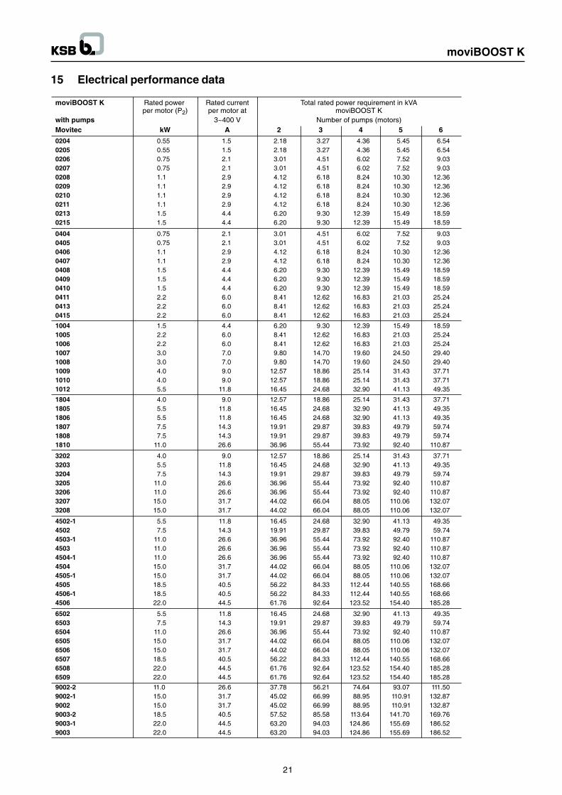
6.2.1 Sizing the power supply cable
The cross-section of the power supply cable must be sized forthe total rated power requirement.
6.3 Protective measures
- Neutralization (4-wire system) PE and N connected- Earthing (5-wire system) PE and N separate- Earth leakage circuit breaker
6.4 Temperature requirements
- Operation 00C to 400CFor temperature exceeding 400C the power must bereduced by 1.5% per additional degree. A maximum coolingair temperature of 450C must not be exceeded.
- Storage up to 550C
6.5 Humidity requirements
- Maximum relative humidity 50% at 400C- Condensation must be effectively precluded.
6.6 Installation altitude
Max. 1000m above sea level. For any higher altitude, the powermust be reduced accordingly. Please contact your nearestKSB customer service centre.
6.7 Pollution exposure
The room air may contain dry dust comparable to that normallyencountered in work environments with no extraordinarymachinery - induced dust accumulation. Exposure to unusuallyhigh dust levels, acids, corrosive gases, salts, etc. must beavoided.
6.8 Checking the voltage
Compare the mains voltage with the name plate data and thecontrol unit�s circuit diagram.
6.9 Logic / circuit diagrams
For each unit are included in the control cabinet, where theymust remain when not in use. This documentation includes aparts list for electric components.
When ordering spare parts for electric components, pleasealways indicate the circuit diagram No.
6.10 Over load relay
For d.o.l. starting the adjusting screw on the motor protectionswitch must be set to the rated motor current.
For the setting range, refer to electrical performance data.Compare these data with the motor rating plate. If there areany discrepancies, the data stated on the rating plate must beobserved.
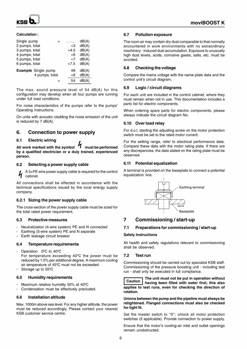
6.11 Potential equalization
A terminal is provided on the baseplate to connect a potentialequalization line.
7 Commissioning / start-up
7.1 Preparations for commissioning / start-up
Safety Instructions
All health and safety regulations relevant to commissioningshall be observed.
7.2 Test run
Commissioning should be carried out by specialist KSB staff.Commissioning of the pressure boosting unit - including testrun - shall only be executed in full compliance.
The unit must not be put in operation withouthaving been filled with water first; this also
applies to test runs, even for checking the direction ofrotation.
Unions between the pump and the pipeline must always beretightened. Flanged connections must also be checkedfor tight fit.
Set the master switch to ��0��; unlock all motor protectionswitches (if applicable). Provide connection to power supply.
Ensure that the motor�s cooling-air inlet and outlet openingsremain unobstructed.
6
moviBOOST K
Open / loosen the vent plugs on the pumps (for vent plugsrefer to the annexed pump operating instructions).
Slowly open the inlet-side shut-off element and prime thesystem until the fluid escapes through all vent holes. Closeand slightly tighten the pump vent plugs.
Switch on the master switch and start up one pump after theother via the corresponding motor protection switch, makingsure that the motor runs in the correct direction of rotation asindicated by the arrow on the motor.
Prior to starting up individual pumps, open the pump�sdischarge-side shut-off element.
When the pumps are running, loosen the vent plugs again tolet any remaining air escape. Then retighten the vent plugscarefully.
Check the pump for smooth running and close the discharge-side shut-off element for a short period in order to verify whetherthe pump reaches the shut-off head.
Having checked each pump as described above, all motorprotection switches may be actuated and the system set toautomatic mode.
On units with manual-0-automatic switch (optional) set allpumps to automatic mode.
Minor leakage of the mechanical seals during start-up isnormal and will cease after a short period of operation.
If the master switch was turned off at any timeduring the above procedure, the system will not
begin operation until after the pre-set delay period.
7.3 Checking the direction of rotation
For test operation each pump must be started up individuallyto check the direction of rotation. If a pump is found to berunning in the wrong direction, switch two phases on the motorterminal board.
7.4 Functional description / Automatic mode
After start-up, pressure boosting units in standard design willrun in automatic mode. For units with manual-0-automaticswitch, set all pumps to automatic mode.
Each pressure boosting unit has been factory-checked andadjusted to the required operating data.
The factory settings may only be altered byauthorized, duly qualified staff.
The PBU comprises 2 to 6 pump units (including stand-bypump). Cascade connection allows operation in line withcurrent consumption; i.e. the individual pumps operate onlyas required by actual demand.
The stand-by pump ensures uninterrupted operation of thesystem, if one pump does not function properly or breaks down.In the case of a pump failure, the next free pump is started upat once and the fault is reported.
The switch-on and switch-off signals for the pumps aretransmitted by the discharge-side pressure transmitter to thesystem�s control element, analyzed and transmitted as anoutput signal via the contractors to the individual pumps.
7.5 Starting the unit
Switch on the master switch to supply the unit with power. Thegreen LED on the control panel indicates the unit�s readinessfor operation.
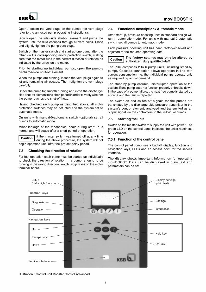
7.5.1 Function of the control panel
The control panel comprises a back-lit display, function andnavigation keys, LEDs and an access point for the serviceinterface.
The display shows important information for operatingmoviBOOST. Data can be displayed in plain text andparameters can be set.
Display settings(plain text)
Settings
Information
Help key
OK key
Service interface
Down
Escape key
Up
Navigation keys
Function keys
Operation
Diagnosis
LED :�traffic light� function
Illustration : Control unit Booster Control Advanced
7
moviBOOST K
7.5.1.1 LEDs
The �traffic light� signals provide information about the pumpsystem�s operating status.
LED :Red : alarm (system stopped)Yellow : warning (system still operating)Green : signals trouble-free operation or readiness foroperation
7.5.1.2 Function keys
You can use the function keys to access the elements at thefirst menu level directly : Operation, Diagnosis, Settings andInformation.
Operation
Diagnosis
Settings
Information
7.5.1.3 Navigation keys
The navigation keys are used for navigating in the menu andfor confirming settings.
Up or Down� Move up / down through the menu options
or� increase / decrease a value when you are
entering numerals
Escape key� Delete / reset entry (the entry is not saved)� Return to the previous menu level
OK key� Confirm a setting� Confirm a menu selection� Move to the next digit when you are entering
numbers.
Help key� Displays a help text for each selected menu
option
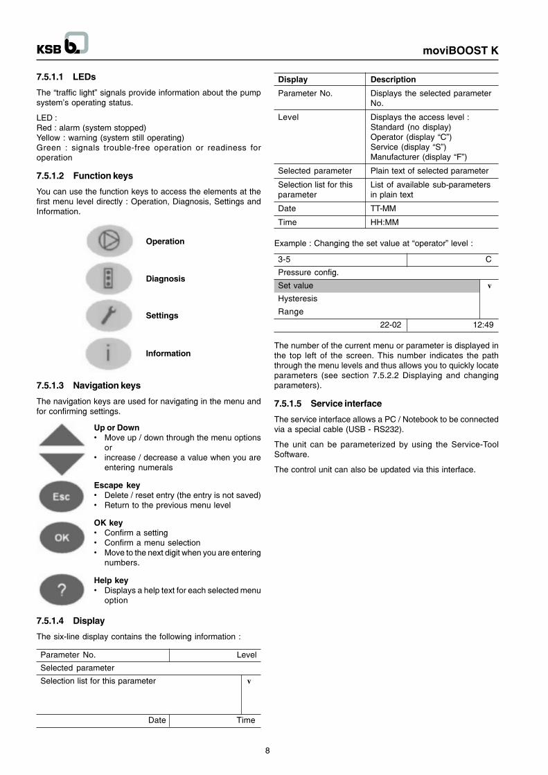
7.5.1.4 Display
The six-line display contains the following information :
Parameter No. Level
Selected parameter
Selection list for this parameter v
Date Time
Display Description
Parameter No. Displays the selected parameterNo.
Level Displays the access level :Standard (no display)Operator (display �C�)Service (display �S�)Manufacturer (display �F�)
Selected parameter Plain text of selected parameter
Selection list for this List of available sub-parametersparameter in plain text
Date TT-MM
Time HH:MM
3-5 C
Pressure config.
Set value vHysteresis
Range
22-02 12:49
Example : Changing the set value at �operator� level :
The number of the current menu or parameter is displayed inthe top left of the screen. This number indicates the paththrough the menu levels and thus allows you to quickly locateparameters (see section 7.5.2.2 Displaying and changingparameters).
7.5.1.5 Service interface
The service interface allows a PC / Notebook to be connectedvia a special cable (USB - RS232).
The unit can be parameterized by using the Service-ToolSoftware.
The control unit can also be updated via this interface.
8
moviBOOST K
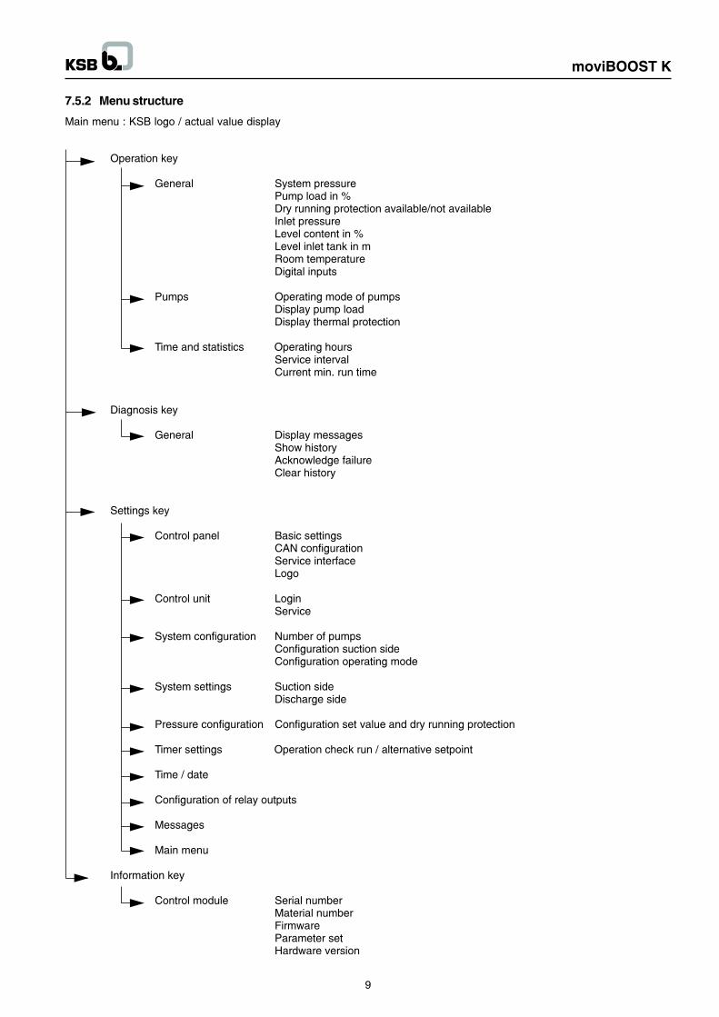
7.5.2 Menu structure
Main menu : KSB logo / actual value display
9
moviBOOST K
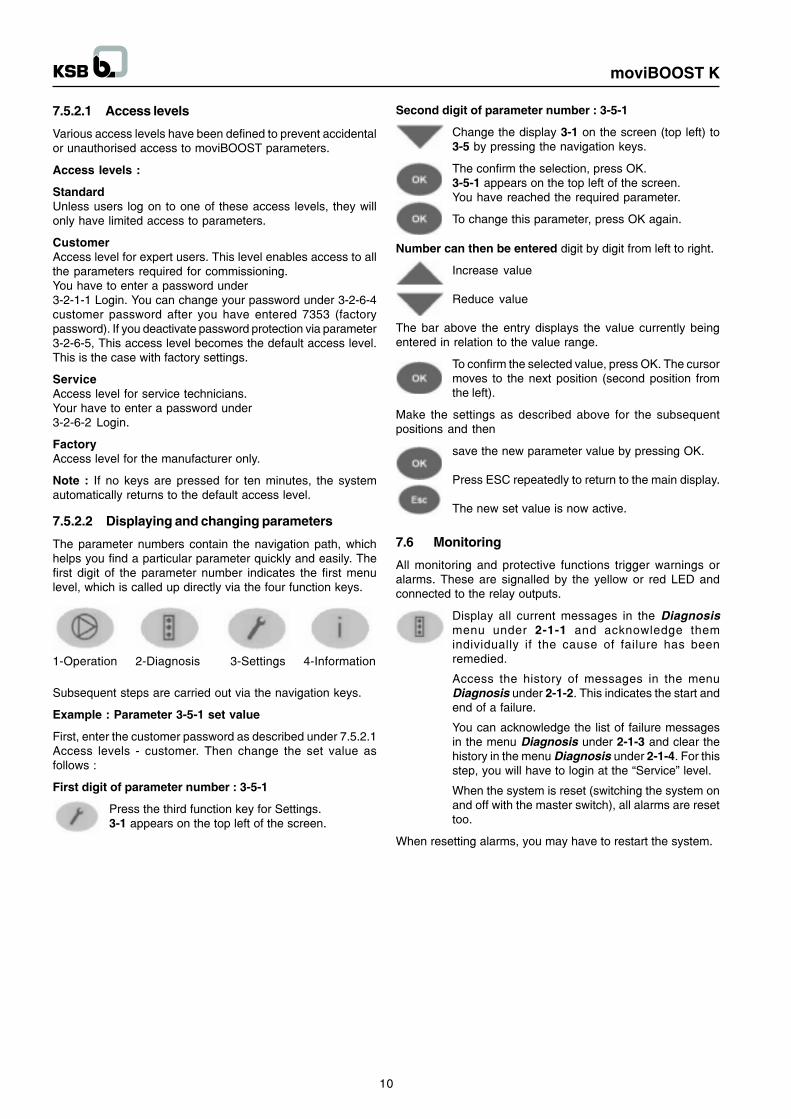
7.5.2.1 Access levels
Various access levels have been defined to prevent accidentalor unauthorised access to moviBOOST parameters.
Access levels :
StandardUnless users log on to one of these access levels, they willonly have limited access to parameters.
CustomerAccess level for expert users. This level enables access to allthe parameters required for commissioning.You have to enter a password under3-2-1-1 Login. You can change your password under 3-2-6-4customer password after you have entered 7353 (factorypassword). If you deactivate password protection via parameter3-2-6-5, This access level becomes the default access level.This is the case with factory settings.
ServiceAccess level for service technicians.Your have to enter a password under3-2-6-2 Login.
FactoryAccess level for the manufacturer only.
Note : If no keys are pressed for ten minutes, the systemautomatically returns to the default access level.
7.5.2.2 Displaying and changing parameters
The parameter numbers contain the navigation path, whichhelps you find a particular parameter quickly and easily. Thefirst digit of the parameter number indicates the first menulevel, which is called up directly via the four function keys.
1-Operation 2-Diagnosis 3-Settings 4-Information
Subsequent steps are carried out via the navigation keys.
Example : Parameter 3-5-1 set value
First, enter the customer password as described under 7.5.2.1Access levels - customer. Then change the set value asfollows :
First digit of parameter number : 3-5-1
Press the third function key for Settings.3-1 appears on the top left of the screen.
Second digit of parameter number : 3-5-1
Change the display 3-1 on the screen (top left) to3-5 by pressing the navigation keys.
The confirm the selection, press OK.3-5-1 appears on the top left of the screen.You have reached the required parameter.
To change this parameter, press OK again.
Number can then be entered digit by digit from left to right.
Increase value
Reduce value
The bar above the entry displays the value currently beingentered in relation to the value range.
To confirm the selected value, press OK. The cursormoves to the next position (second position fromthe left).
Make the settings as described above for the subsequentpositions and then
save the new parameter value by pressing OK.
Press ESC repeatedly to return to the main display.
The new set value is now active.
7.6 Monitoring
All monitoring and protective functions trigger warnings oralarms. These are signalled by the yellow or red LED andconnected to the relay outputs.
Display all current messages in the Diagnosismenu under 2-1-1 and acknowledge themindividually if the cause of failure has beenremedied.
Access the history of messages in the menuDiagnosis under 2-1-2. This indicates the start andend of a failure.
You can acknowledge the list of failure messagesin the menu Diagnosis under 2-1-3 and clear thehistory in the menu Diagnosis under 2-1-4. For thisstep, you will have to login at the �Service� level.
When the system is reset (switching the system onand off with the master switch), all alarms are resettoo.
When resetting alarms, you may have to restart the system.
10
moviBOOST K
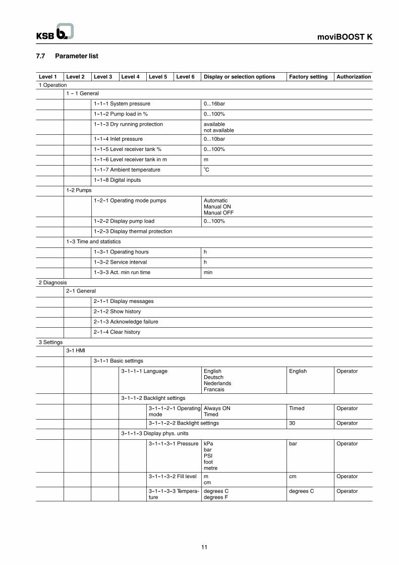
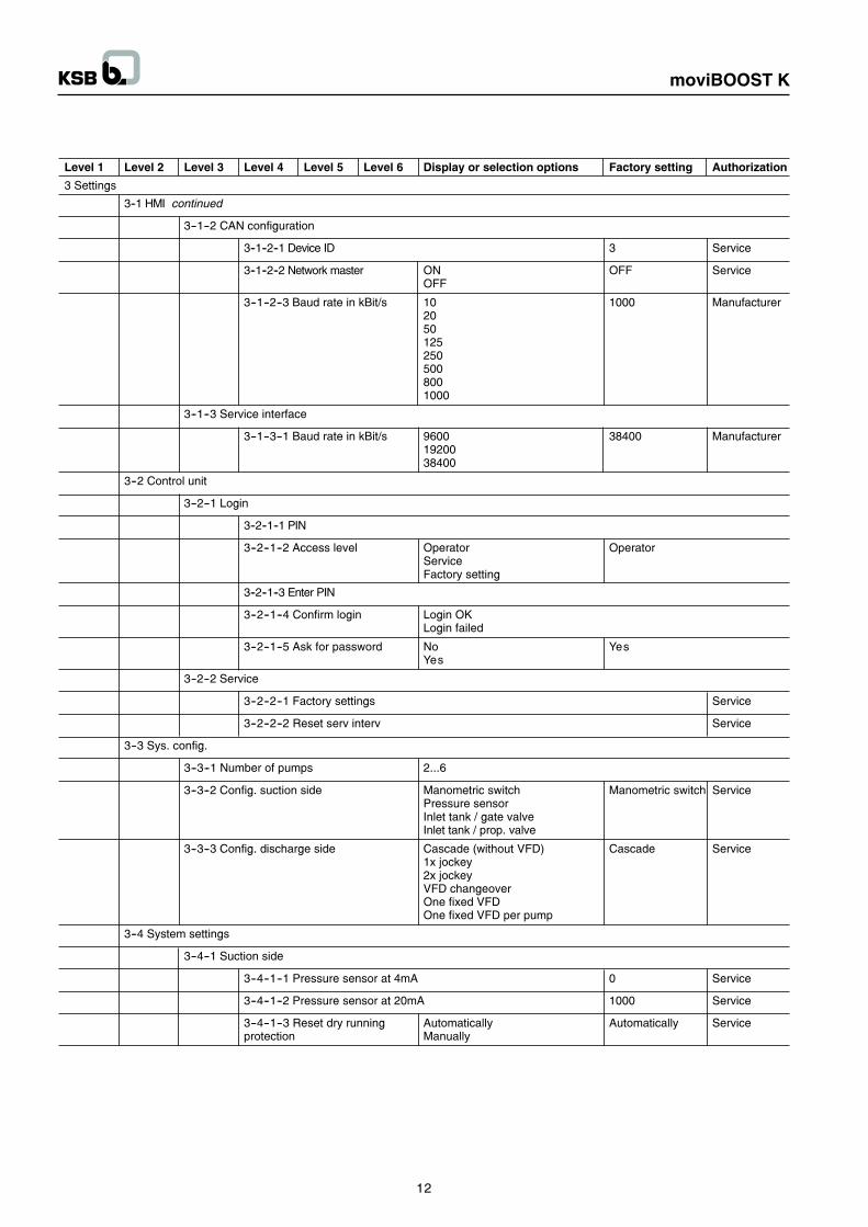
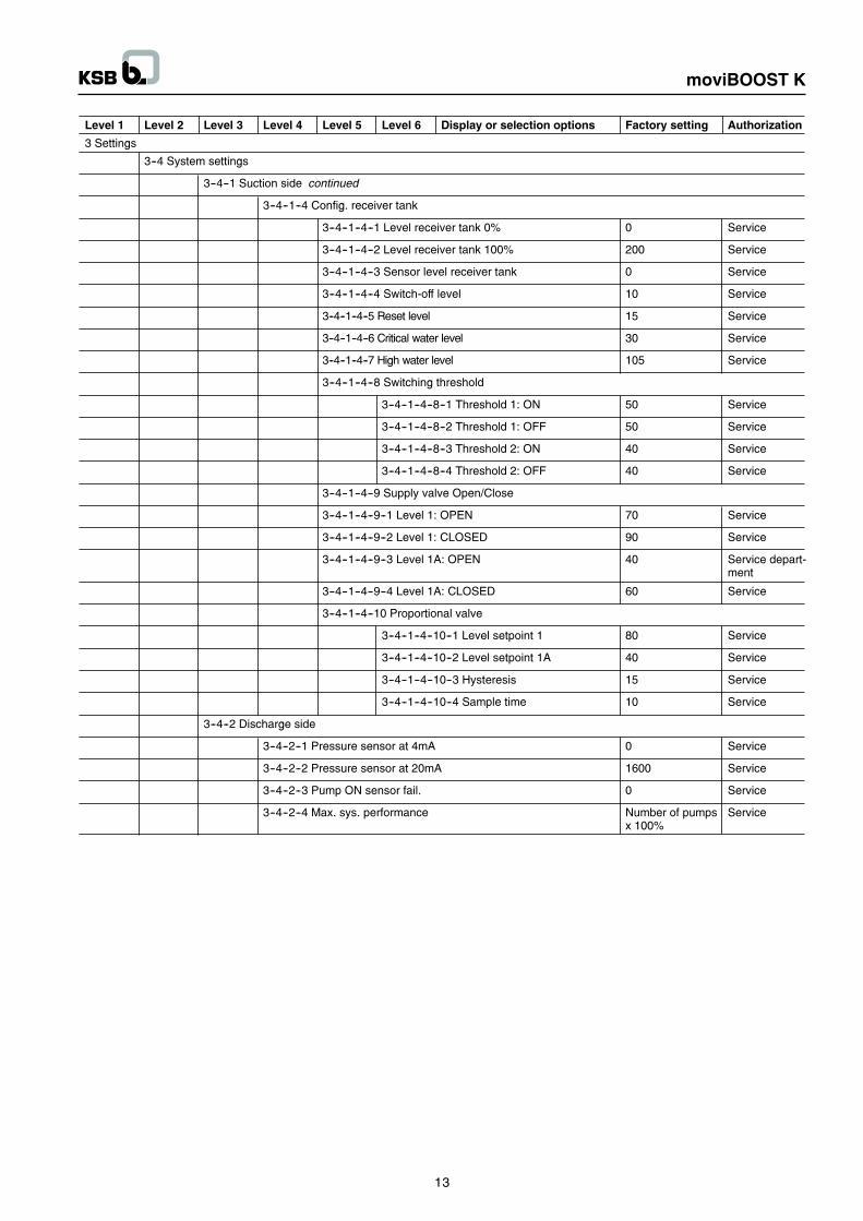
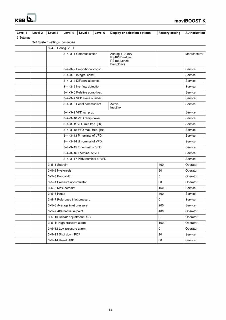
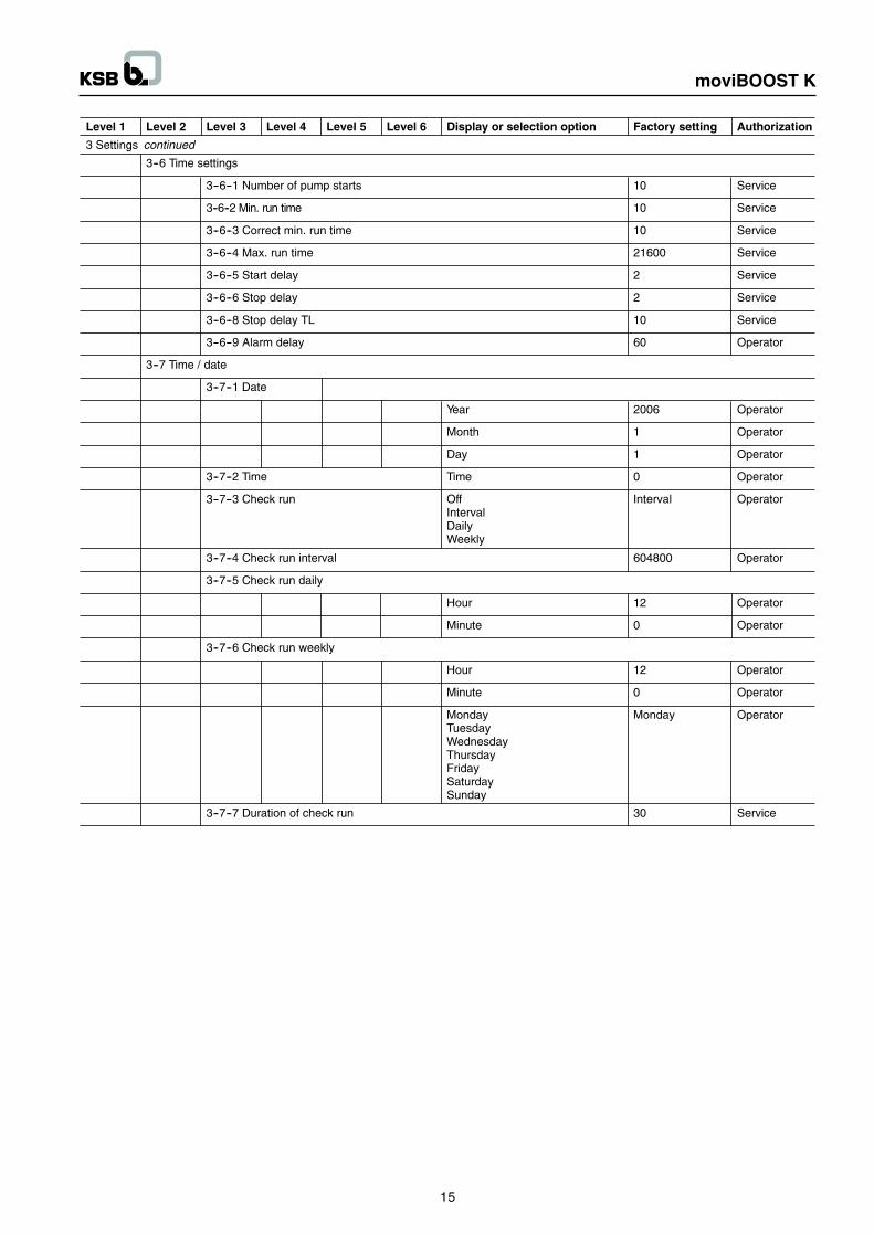
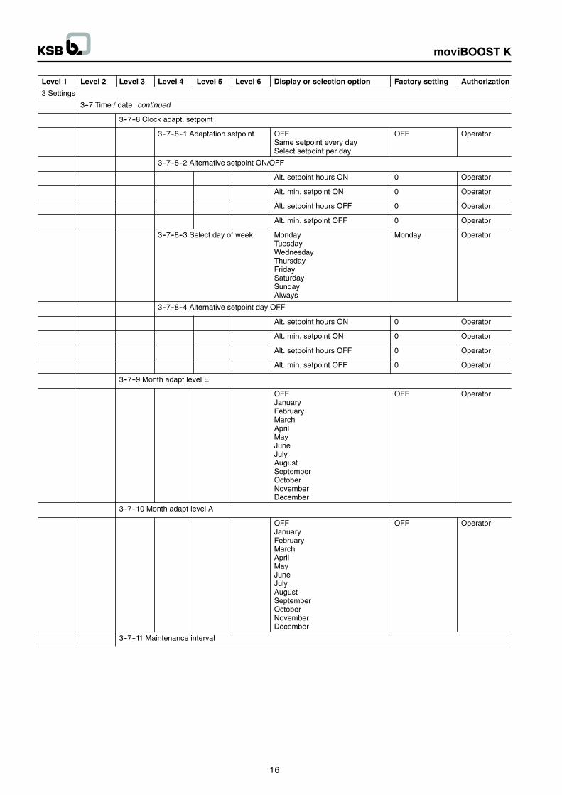
7.7 Parameter list
11
moviBOOST K
12
moviBOOST K
13
moviBOOST K
14
moviBOOST K
15
moviBOOST K
16
moviBOOST K
17
moviBOOST K
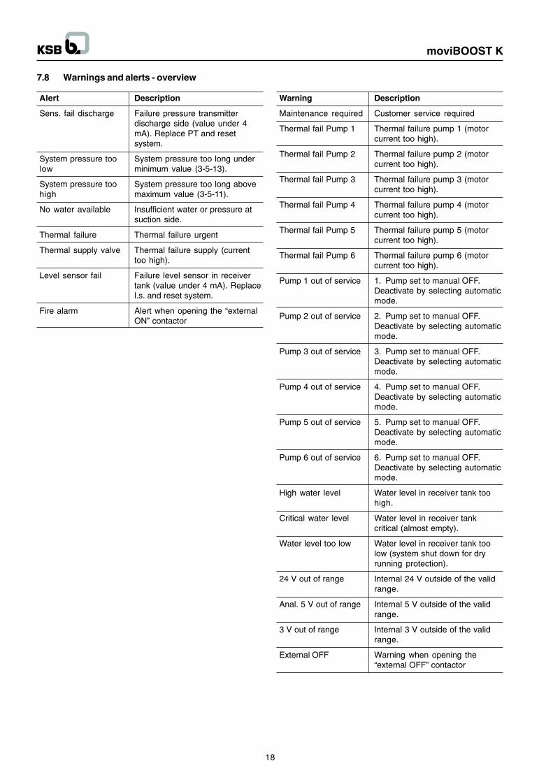
7.8 Warnings and alerts - overview
Alert Description
Sens. fail discharge Failure pressure transmitterdischarge side (value under 4mA). Replace PT and resetsystem.
System pressure too System pressure too long underlow minimum value (3-5-13).
System pressure too System pressure too long abovehigh maximum value (3-5-11).
No water available Insufficient water or pressure atsuction side.
Thermal failure Thermal failure urgent
Thermal supply valve Thermal failure supply (currenttoo high).
Level sensor fail Failure level sensor in receivertank (value under 4 mA). Replacel.s. and reset system.
Fire alarm Alert when opening the �externalON� contactor
Warning Description
Maintenance required Customer service required
Thermal fail Pump 1 Thermal failure pump 1 (motorcurrent too high).
Thermal fail Pump 2 Thermal failure pump 2 (motorcurrent too high).
Thermal fail Pump 3 Thermal failure pump 3 (motorcurrent too high).
Thermal fail Pump 4 Thermal failure pump 4 (motorcurrent too high).
Thermal fail Pump 5 Thermal failure pump 5 (motorcurrent too high).
Thermal fail Pump 6 Thermal failure pump 6 (motorcurrent too high).
Pump 1 out of service 1. Pump set to manual OFF.Deactivate by selecting automaticmode.
Pump 2 out of service 2. Pump set to manual OFF.Deactivate by selecting automaticmode.
Pump 3 out of service 3. Pump set to manual OFF.Deactivate by selecting automaticmode.
Pump 4 out of service 4. Pump set to manual OFF.Deactivate by selecting automaticmode.
Pump 5 out of service 5. Pump set to manual OFF.Deactivate by selecting automaticmode.
Pump 6 out of service 6. Pump set to manual OFF.Deactivate by selecting automaticmode.
High water level Water level in receiver tank toohigh.
Critical water level Water level in receiver tankcritical (almost empty).
Water level too low Water level in receiver tank toolow (system shut down for dryrunning protection).
24 V out of range Internal 24 V outside of the validrange.
Anal. 5 V out of range Internal 5 V outside of the validrange.
3 V out of range Internal 3 V outside of the validrange.
External OFF Warning when opening the�external OFF� contactor
18
moviBOOST K
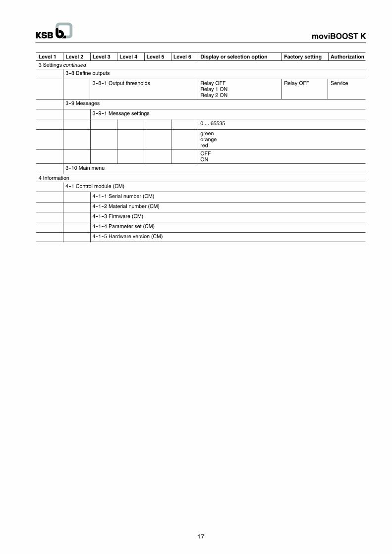
7.9 Adjusting the settings
7.9.1 Setting the set pressure
The unit�s default setting equals the set pressure indicated onthe rating plate.
If the set value needs to be adjusted to the plant conditions,parameter 3-5-1 has to be changed.
First, enter the customer password as described under 7.5.2.1Access levels - customer. Then change the set value asdescribed under 7.5.2.2.
7.9.2 Further settings
If any further settings have to be adjusted to the plantconditions, change their parameters as described in section7.5.2.2. Refer to section 7.5.2 for the menu structure.
7.10 Connection remote-OFF
The remote-OFF connection is a NC contact. When this contactis open, alle pumps which are in operation will cut out after theset delay, one after the other.
When this contact is closed, the pumps will start up again inline with the demand.
7.11 Connection fire alarm
The fire alarm connection is a NC contact. When this contactis opened, all pumps are started up one after the other afterthe set cut-in delay and an alarm signal (red LED) is shown.The dry running protection and remote-Off functions areignored.
When this contact is closed, the pumps will stop again in linewith the demand. The alarm is cleared.
7.12 Shutdown
As long as the system is out of operation, water is supplieddirectly through the system at Pvor.- Set master switch to �0�.- For prolonged shutdown, drain the system.
8 Dismantling / reassembling thepumps
The pumps can be individually dismantled to facilitatemaintenance.
Dismantling sequence :
1. Disconnect the pump from the power supply.
De-energize the pump via the motor protection switch.
2. Close the suction and discharge side valves.
Reassembly :
1. Insert pump (original spare part only), always use newgaskets for unions and tighten. Check tightness of screwedconnection !
2. Fasten the pump foot to the baseplate using hexagon headbolts.
3. Connect to power supply, switch on motor protection switch.
9 Returning to serviceReturn the unit to service as described under Commissioning/start-up.
10 Maintenance
10.1 Operating monitoring
All technical systems require a certain degree of monitoring.The same applies to our package systems for which thefollowing checks and inspections are prescribed :
- The system�s readiness for operation.
- Check the operation check run, if activated.
- With the aid of the pressure gauge, compare the start-upand switch-off pressures of the pumps with the data on thename plate.
- The pump�s mechanical seal allows little or no visibleleakage. It is maintenance-free.
- The motor requires practically no maintenance.
- Verify whether the pre-set accumulator pressurecorresponds to the data in the pre-set pressure table (seesection 14). Close the shut-off elements under theaccumulator for this purpose and drain the accumulatorvia the drain valve. Remove the protective cap of theaccumulator valve and check the pressure with the aid of atyre pressure gauge. Add nitrogen as necessary.
Do not add any other gases.
11 Work on the control cabinetEach pump can be switched off via the motor protectionswitch.
The motor protection switches are fitted with a padlockas a standard.
The pumps can be stopped by using the manual-0-automatic switch (supplementary equipment).However, this will not disconnect the system fromthe power supply, i.e. all electric devices are still live,even if the pumps are not in automatic operation mode.
Prior to working on the control cabinet or opening themotor terminal box, set the master switch to �0� andunscrew the back-up fuse.
Do not tamper with the control unit, which should only beserviced by KSB�s customer service.
Prior to opening any electric equipment such as controlcabinet and motor terminal box, de-energize the system.
Even when the mains lamp goes out, check whether allphases are actually dead prior to performing any work onthe control cabinet.
Maintenance of the control cabinet
It is recommended to have the control cabinet serviced once ayear. For this purpose you can take out a maintenance contractwith one of KSB�s Service Partners.
19
moviBOOST K
12 InspectionKSB offers inspection services to relieve you as far as possibleof the routine necessity of inspecting your moviBOOSTpackage system(s). Take advantage of this additional after-sales service by taking out a maintenance contract with KSB.Get in touch with your Service Partner of details.
13 Check listIn the event that you decide to conduct your own inspections,proceed according to the following check list at least once ayear :
1. Check the pumps and drives for quiet running and themechanical seal for integrity.
2. Check the flexible transmission element for wear.
3. Check the function and seal condition of the shut-off, drainand non-return valves.
4. Clean the strainer in the pressure reducer (if applicable).
5. Check the expansion joints for wear (if applicable).
6. Verify the pre-set pressure level and check the accumulatorfor integrity, if required (see section 14 pre-set pressuretable).
7. Check the automatic control unit / switchgear.
8. Check the ON and OFF points of the system.
9. Check if the functional check run is working.
10. Check the function of the overall system and compare theactual data with the name plate data.
11. Check the water inlet, pre-set pressure, lack-of-watermonitoring, flow monitoring and pressure reducer.
12. Check the inlet tank and float valve, if applicable. Checkthe overflow for integrity and cleanliness.
14 Pre-set pressureThe pre-set pressure in the accumulator should be set to avalue which is 10% lower than the set start-up pressure.
The setting can be effected via a valve located under the coverat the top of the accumulator.
Pre-set pressure tablePre-set pressure of accumulatorp = 0.9 x pE; pE = system start-up pressure
Recommendation
Fill the accumulator with nitrogen only (risk of corrosion).
The stated values are average values. Tests on accumulatorshave shown that
pressures >3 bar for factor 0.9 and
pressures <3 bar for factor 0.8
result in the best storage volumes.
Example :
pE = 5 bar pre-set pressure 5 x 0.9 = 4.5 bar
pE = 2 bar pre-set pressure 2 x 0.8 = 1.6 bar
20
moviBOOST K
15 Electrical performance data
21
moviBOOST K
16 Shutoff head
22
moviBOOST K
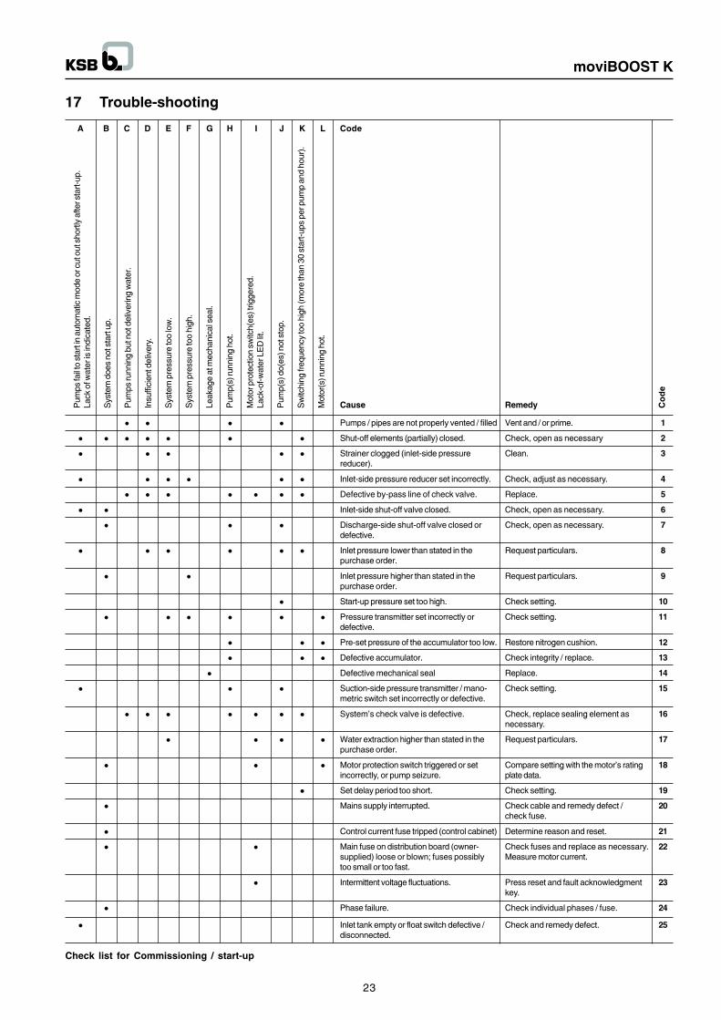
17 Trouble-shooting
Pum
ps fa
il to
sta
rt in
aut
omat
ic m
ode
or c
ut o
ut s
hortl
y af
ter s
tart-
up.
Lack
of w
ater
is in
dica
ted.
Sys
tem
doe
s no
t sta
rt up
.
Pum
ps ru
nnin
g bu
t not
del
iver
ing
wat
er.
Insu
ffici
ent d
eliv
ery.
Sys
tem
pre
ssur
e to
o lo
w.
Sys
tem
pre
ssur
e to
o hi
gh.
Leak
age
at m
echa
nica
l sea
l.
Pum
p(s)
runn
ing
hot.
Mot
or p
rote
ctio
n sw
itch(
es) t
rigge
red.
Lack
-of-w
ater
LE
D li
t.
Pum
p(s)
do(
es) n
ot s
top.
Sw
itchi
ng fr
eque
ncy
too
high
(mor
e th
an 3
0 st
art-u
ps p
er p
ump
and
hour
).
Mot
or(s
) run
ning
hot
.
A B C D E F G H I J K L Code
l l l l Pumps / pipes are not properly vented / filled Vent and / or prime. 1
l l l l l l l Shut-off elements (partially) closed. Check, open as necessary 2
l l l l l Strainer clogged (inlet-side pressure Clean. 3reducer).
l l l l l l Inlet-side pressure reducer set incorrectly. Check, adjust as necessary. 4
l l l l l l l Defective by-pass line of check valve. Replace. 5
l l Inlet-side shut-off valve closed. Check, open as necessary. 6
l l l Discharge-side shut-off valve closed or Check, open as necessary. 7defective.
l l l l l l Inlet pressure lower than stated in the Request particulars. 8purchase order.
l l Inlet pressure higher than stated in the Request particulars. 9purchase order.
l Start-up pressure set too high. Check setting. 10
l l l l l l Pressure transmitter set incorrectly or Check setting. 11defective.
l l l Pre-set pressure of the accumulator too low. Restore nitrogen cushion. 12
l l l Defective accumulator. Check integrity / replace. 13
l Defective mechanical seal Replace. 14
l l l Suction-side pressure transmitter / mano- Check setting. 15metric switch set incorrectly or defective.
l l l l l l l System�s check valve is defective. Check, replace sealing element as 16necessary.
l l l l Water extraction higher than stated in the Request particulars. 17purchase order.
l l l Motor protection switch triggered or set Compare setting with the motor�s rating 18incorrectly, or pump seizure. plate data.
l Set delay period too short. Check setting. 19
l Mains supply interrupted. Check cable and remedy defect / 20check fuse.
l Control current fuse tripped (control cabinet) Determine reason and reset. 21
l l Main fuse on distribution board (owner- Check fuses and replace as necessary. 22supplied) loose or blown; fuses possibly Measure motor current.too small or too fast.
l Intermittent voltage fluctuations. Press reset and fault acknowledgment 23key.
l Phase failure. Check individual phases / fuse. 24
l Inlet tank empty or float switch defective / Check and remedy defect. 25disconnected.
Co
de
Cause Remedy
Check list for Commissioning / start-up
23
moviBOOST K
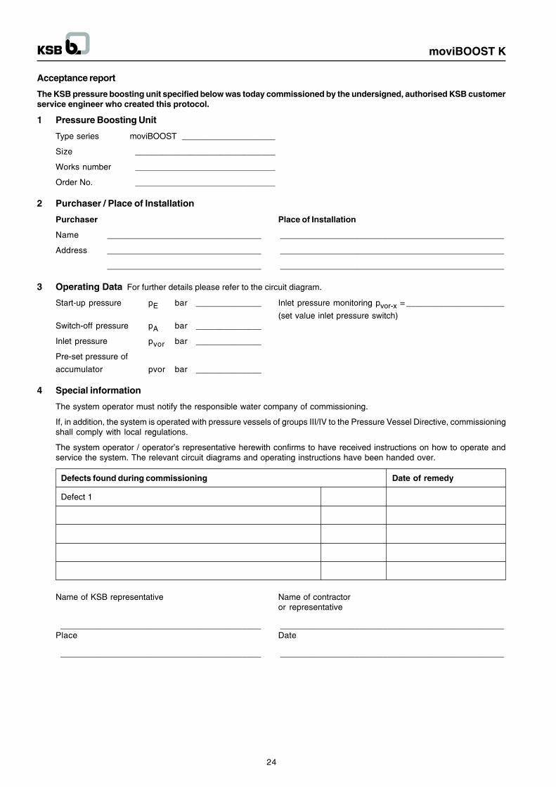
Acceptance report
The KSB pressure boosting unit specified below was today commissioned by the undersigned, authorised KSB customerservice engineer who created this protocol.
1 Pressure Boosting Unit
Type series moviBOOST ____________________
Size ______________________________
Works number ______________________________
Order No. ______________________________
2 Purchaser / Place of Installation
Purchaser Place of Installation
Name _________________________________ ________________________________________________
Address _________________________________ ________________________________________________
_________________________________ ________________________________________________
3 Operating Data For further details please refer to the circuit diagram.
Start-up pressure pE bar ______________ Inlet pressure monitoring pvor-x = _____________________
(set value inlet pressure switch)Switch-off pressure pA bar ______________
Inlet pressure pvor bar ______________
Pre-set pressure of
accumulator pvor bar ______________
4 Special information
The system operator must notify the responsible water company of commissioning.
If, in addition, the system is operated with pressure vessels of groups III/IV to the Pressure Vessel Directive, commissioningshall comply with local regulations.
The system operator / operator�s representative herewith confirms to have received instructions on how to operate andservice the system. The relevant circuit diagrams and operating instructions have been handed over.
Defects found during commissioning Date of remedy
Defect 1
Name of KSB representative Name of contractoror representative
___________________________________________ ________________________________________________Place Date
___________________________________________ ________________________________________________
24
moviBOOST K
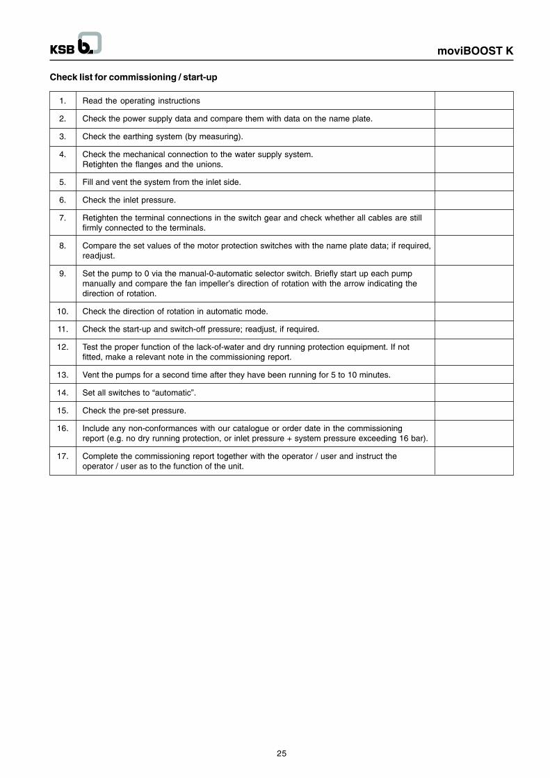
Check list for commissioning / start-up
1. Read the operating instructions
2. Check the power supply data and compare them with data on the name plate.
3. Check the earthing system (by measuring).
4. Check the mechanical connection to the water supply system.Retighten the flanges and the unions.
5. Fill and vent the system from the inlet side.
6. Check the inlet pressure.
7. Retighten the terminal connections in the switch gear and check whether all cables are stillfirmly connected to the terminals.
8. Compare the set values of the motor protection switches with the name plate data; if required,readjust.
9. Set the pump to 0 via the manual-0-automatic selector switch. Briefly start up each pumpmanually and compare the fan impeller�s direction of rotation with the arrow indicating thedirection of rotation.
10. Check the direction of rotation in automatic mode.
11. Check the start-up and switch-off pressure; readjust, if required.
12. Test the proper function of the lack-of-water and dry running protection equipment. If notfitted, make a relevant note in the commissioning report.
13. Vent the pumps for a second time after they have been running for 5 to 10 minutes.
14. Set all switches to �automatic�.
15. Check the pre-set pressure.
16. Include any non-conformances with our catalogue or order date in the commissioningreport (e.g. no dry running protection, or inlet pressure + system pressure exceeding 16 bar).
17. Complete the commissioning report together with the operator / user and instruct theoperator / user as to the function of the unit.
25
moviBOOST K
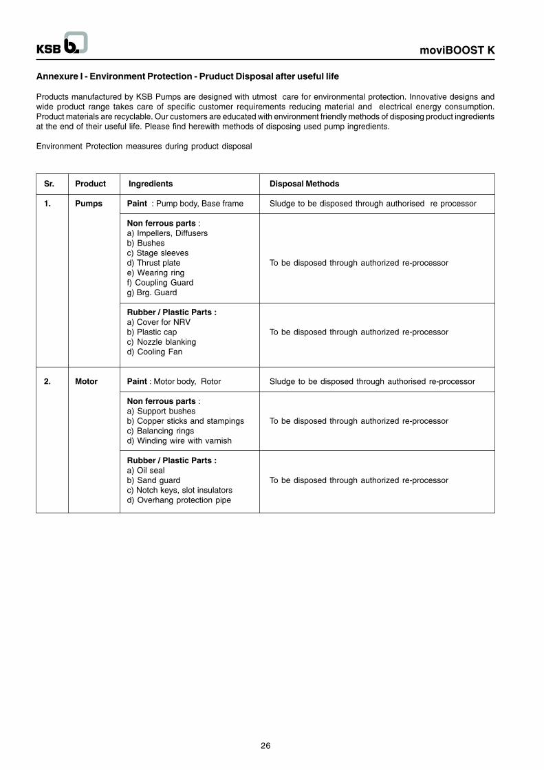
Annexure I - Environment Protection - Pruduct Disposal after useful life
Products manufactured by KSB Pumps are designed with utmost care for environmental protection. Innovative designs andwide product range takes care of specific customer requirements reducing material and electrical energy consumption.Product materials are recyclable. Our customers are educated with environment friendly methods of disposing product ingredientsat the end of their useful life. Please find herewith methods of disposing used pump ingredients.
Environment Protection measures during product disposal
Sr. Product Ingredients Disposal Methods
1. Pumps Paint : Pump body, Base frame Sludge to be disposed through authorised re processor
Non ferrous parts :a) Impellers, Diffusersb) Bushesc) Stage sleevesd) Thrust plate To be disposed through authorized re-processore) Wearing ringf) Coupling Guardg) Brg. Guard
Rubber / Plastic Parts :a) Cover for NRVb) Plastic cap To be disposed through authorized re-processorc) Nozzle blankingd) Cooling Fan
2. Motor Paint : Motor body, Rotor Sludge to be disposed through authorised re-processor
Non ferrous parts :a) Support bushesb) Copper sticks and stampings To be disposed through authorized re-processorc) Balancing ringsd) Winding wire with varnish
Rubber / Plastic Parts :a) Oil sealb) Sand guard To be disposed through authorized re-processorc) Notch keys, slot insulatorsd) Overhang protection pipe
26
moviBOOST K
NOTES