Embed Size (px)
Citation preview
Moving object detection from a point cloudusing photometric and depth consistencies
Atsushi Takabe∗, Hikari Takehara∗, Norihiko Kawai∗, Tomokazu Sato∗,Takashi Machida†, Satoru Nakanishi† and Naokazu Yokoya∗
∗Nara Institute of Science and Technology,8916-5, Takayama-cho, Ikoma, Nara, Japan
Email: [email protected]†TOYOTA Central Research and Development Labs,
41-1, Yokomichi, Nagakute, Aichi, Japan
Abstract—3D models of outdoor environments have been usedfor several applications such as a virtual earth system and avision-based vehicle safety system. 3D data for constructing such3D models are often measured by an on-vehicle system equippedwith laser rangefinders, cameras, and GPS/IMU. However, 3Ddata of moving objects on streets lead to inaccurate 3D modelswhen modeling outdoor environments. To solve this problem,this paper proposes a moving object detection method for pointclouds by minimizing an energy function based on photometricand depth consistencies assuming that input data consist ofsynchronized point clouds, images, and camera poses from asingle sequence captured with a moving on-vehicle system.
I. INTRODUCTION
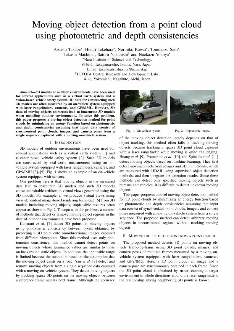
3D models of outdoor environments have been used forseveral applications such as a virtual earth system [1] anda vision-based vehicle safety system [2]. Such 3D modelsare constructed by real-world measurement using an on-vehicle system equipped with laser rangefinders, cameras, andGPS/IMU [3]–[5]. Fig. 1 shows an example of an on-vehiclesystem equipped with sensors.
One problem here is that moving objects in the measureddata lead to inaccurate 3D models and such 3D modelscause undesirable artifacts in virtual views generated using the3D models. For example, if we produce virtual views usingview-dependent image-based rendering technique [6] from 3Dmodels including moving objects, implausible textures oftenappear as shown in Fig. 2. To cope with this problem, a numberof methods that detect or remove moving object regions in thedata of outdoor environments have been proposed.
Kanatani et al. [7] detect 3D points on moving objectsusing photometric consistency between pixels obtained byprojecting a 3D point onto omnidirectional images capturedfrom different viewpoints. Since this method uses only pho-tometric consistency, this method cannot detect points onmoving objects whose luminance values are similar to thoseon background static objects. In addition, the applicable rangeis limited because the method is based on the assumption thatthe moving object exists on a road. Yan et al. [8] detect andremove moving objects from a single sequence data capturedwith a moving on-vehicle system. They detect moving objectsby tracking sparse 3D points on the moving objects betweena reference frame and its next frame. Although the accuracy
Fig. 1. On-vehicle system. Fig. 2. Implausible image.
of the moving object detection largely depends on that ofobject tracking, this method often fails in tracking movingobjects because tracking a sparse 3D point cloud capturedwith a laser rangefinder while moving is quite challenging.Huang et al. [9], Premebida et al. [10], and Spinello et al. [11]detect moving objects based on machine learning. They firstdetect moving objects from images and 3D point clouds, whichare measured with LIDAR, using supervised object detectionmethods, and then integrate the detection results. Since thesemethods can detect only specified moving objects such ashumans and vehicles, it is difficult to detect unknown movingobjects.
This paper proposes a novel moving object detection methodfor 3D point clouds by minimizing an energy function basedon photometric and depth consistencies assuming that inputdata consist of synchronized point clouds, images, and cameraposes measured with a moving on-vehicle system from a singlesequence. The proposed method can detect arbitrary movingobjects in unconstrained regions without tracking movingobjects.
II. MOVING OBJECT DETECTION FROM A POINT CLOUD
The proposed method detects 3D points on moving ob-jects frame-by-frame using 3D point clouds, images, andcamera poses of multiple frames measured by a moving on-vehicle system equipped with laser rangefinders, cameras,and GPS/IMU. Here, a 3D point cloud, an image and acamera pose are synchronously obtained in each frame. Sincethe 3D point cloud is obtained by raster-scanning a targetenvironment in whole directions around the laser rangefinders,the relationship among neighboring 3D points is known.

In this study, assuming that luminance, position and shapeof static objects are fixed during a short time period, wedetect the 3D points on moving objects by minimizing anenergy function based on photometric and depth consistenciesbetween multiple frames using graph cuts [12]. In addition, toimprove the detection accuracy, we design a function that eval-uates the likelihood of moving objects from the relationshipbetween manually labeled objects and their photometric anddepth consistencies in measured data, and use it for the energyfunction. In the following sections, we describe the definitionof the energy function, photometric consistency, depth consis-tency, and the function for evaluating the likelihood of movingobjects.
A. Definition of the energy function
The proposed method assigns moving or static label to each3D point so as to minimize an energy function based onthe likelihood of moving objects and the relationship amongneighboring 3D points. Specifically, we define energy functionE with respect to label X for target frame as follows:
E(X) =∑v∈V
gv(Xv) + κ∑
(u,v)∈A
hu,v(Xu, Xv), (1)
where gv is an data term that measures the likelihood of thelabel Xv for a 3D point v, hu,v is an smoothness term betweenlabels of two neighboring 3D points u and v, V is a set ofmeasured 3D points in target frame, A is a set of pairs oftwo neighboring points (u, v), and κ is a weight to controlthe contribution of the second term versus the first term.
Data term gv is defined on the basis of the likelihood ofmoving objects based on photometric consistency MP,v andthe likelihood of moving objects based on depth consistencyMD,v for 3D point v as follows:
gv(Xv) =
{(1−MD,v) + α(1−MP,v) (Xv : moving)MD,v + αMP,v (Xv : static),
(2)where the range of MP,v and MD,v is the closed interval [0, 1]and α is a weight to control the contribution of MP,v versusMD,v. When the likelihood of moving objects is large, labelXv tends to become moving so that gv gets small, and viceversa. The likelihoods of moving objects MP,v and MD,v aredescribed in the following section.
Smoothness term hu,v is defined on the basis of thedifference between luminance values Inv and Inu (which are Vin HSV color space) and the difference between depth valuesdnv and dnu at the projected positions of two neighboring 3Dpoints u and v on target frame n as follows:
hu,v(Xu, Xv) =
{0 (Xv = Xu)
1|dnu−dnv |+|Inu−Inv |+ε
(Xv 6= Xu),(3)
where ε is a positive constant value to make the denominatorof the lower case in Eq. (3) non-zero. When different labelsare assigned to two neighboring points, hu,v gets small if thedifferences of luminance values Inv and Inu and depth valuesdnv and dnu are large. Therefore, different labels tend to beallowed for the neighboring points in such a case.
Target frame 𝑛 Frame 𝑚
Input images
Point 𝑣
𝐼𝑣𝑚𝐼𝑣
𝑛
Fig. 3. Photometric consistency.
Point 𝑣
Dense depth map𝑑𝑣′𝑚
Target frame 𝑛 Frame 𝑚
𝑑𝑣𝑚
Point 𝑣′
Fig. 4. The case of occlusion.
B. Photometric consistency
As illustrated in Fig. 3, in the case of projecting 3D point von a moving object measured in target frame n onto images ofdifferent frames, luminance values of the projected positionsoften vary because different objects often exist on the projectedpositions. Therefore, the proposed method projects 3D pointsof target frame n onto images of multiple frames m (n−N ≤m ≤ n+N ), and evaluates the likelihood of moving objectson the basis of the differences of luminance values.
Specifically, we calculate the likelihood of moving objectsbased on photometric consistency MP,v for 3D point v asfollows:
MP,v = FP
(maxm
(Ierr(m, v))), (4)
where Ierr(m, v) is defined using luminance values Inv andImv at the projected positions of 3D point v on target frame nand another frame m, respectively, as follows:
Ierr(m, v) =
{0 (dmv − dmv′ > T )|Inv − Imv | (otherwise).
(5)
If 3D point v measured in target frame n is occluded indifferent frame m, a different 3D point v′ is observed at theprojected position of 3D point v on frame m. This means thatthe projected positions of v and v′ on frame m are the same.In this case, point depth dmv at 3D point v on frame m is largerthan the observed depth dmv′ at the projected position of 3Dpoint v as illustrated in Fig. 4. Thus, we assume that a 3D pointv is occluded in frame m if dmv − dmv′ > T is satisfied, whereT (≥ 0) is a threshold, and we set luminance error Ierr(m, v)as zero in this case. The function FP (·) (0 ≤ FP (·) ≤ 1) inEq. (4) evaluates the likelihood of moving objects on the basisof the relationship between manually labeled objects and their

Point 𝑣
Dense depth map
𝑑𝑣′𝑚
𝑑𝑣𝑚
𝑑𝑒𝑟𝑟 𝑚, 𝑣
Target frame 𝑛 Frame 𝑚
Point 𝑣′
Fig. 5. Depth consistency.
photometric consistencies in measured data. We describe thedetails of function FP in Section II-D.
C. Depth consistency
As with the photometric consistency in the previous section,in the case of projecting 3D point v on a moving objectmeasured in target frame n onto depth maps of a differentframe m, an observed depth dmv′ at the projected position of3D point v on frame m differs from dmv because differentobjects exist on the projected positions as illustrated in Fig. 5.Accordingly, the proposed method projects 3D points in targetframe n onto depth maps of multiple frames m, and evaluatesthe likelihood of moving objects on the basis of the differenceof depth values. It should be noted here that we generate adense depth map in each frame by linearly interpolating depthvalues using connected neighboring 3D points on the depthmap as shown in Fig. 6 because depth maps generated fromsparse 3D points have missing values.
Specifically, we calculate the likelihood of moving objectsbased on depth consistency MD,v as follows:
MD,v = FD
(maxm
(derr(m, v))), (6)
where derr(m, v) is defined using depth dmv and observeddepth dmv′ at the projected position of 3D point v onto framem as follows:
derr(m, v) =
{0 (dmv − dmv′ > T )|dmv′ − dmv | (otherwise).
(7)
As with the photometric consistency, if |dmv − dmv′ | > T issatisfied, i.e., a occlusion occurs, we set depth error derr(m, v)as zero. The function FD(·) (0 ≤ FD(·) ≤ 1) in Eq. (6)evaluates the likelihood of moving objects on the basis ofrelationship between manually labeled objects and their depthconsistencies in measured data. We describe the details offunction FD in the next section.
D. Definition of function for evaluating the likelihood ofmoving objects
In order to improve the detection accuracy, we design FP
and FD that evaluate the likelihood of moving objects fromthe relationship between manually labeled objects and theirphotometric and depth errors, which are calculated by Eq. (5)and Eq. (7), respectively.
(a) Projected 3D point cloud
(b) Dense depth map
Fig. 6. Interpolation of depth map.
Fig. 7. Manually labeled moving objects.
Specifically, we first manually assign moving or static labelto measured 3D points in order to make the ground truthas shown in Fig. 7. Next, we compute histograms of theluminance and depth error for moving and static labels, re-spectively. Finally, we calculate ratios of the number of movinglabels to the entire number for each bin in the histograms, andstore the ratios into lookup tables that are used as the functionsof the likelihood of moving objects FP and FD.
III. EXPERIMENTS
To verify the effectiveness of the proposed method, wedetected 3D points on moving objects using a single sequenceof 3D point clouds, images, and camera poses that are syn-chronously acquired with a moving on-vehicle system, andperformed quantitative evaluations.
A. Experimental conditions
We applied the proposed method to the public data setsfrom KITTI [13], which are captured by a moving on-vehiclesystem. These data sets consist of synchronized point cloudsmeasured by an omnidirectional laser rangefinder (VelodyneHDL-64E), images captured by a camera (Point Grey Flea 2(FL2-14S3C-C)), and camera poses measured by a GPS/IMU(OXTS RT 3003). The specifications of the sensors are shownin Table I. First, we gave the ground truth to 10 frames indata set A shown in Fig. 8 to calculate the function for eval-uating the likelihood of moving objects. Then, we applied theproposed method with the calculated function to respective 20frames in data sets B, C, and D (shown in Figs.9 - 11) to detect

TABLE ISPECIFICATIONS OF SENSORS.
Velodyne HDL-64EData acquisition 10HzAcquisition points About 130,000 pointsAngular resolution 0.09◦
Range of the declination angle 0◦-26.8◦
Measurement error of the distance ±20mmRange of the measurement ≤ 120m
Point Grey Flea 2Data acquisition 10HzResolution(pixel) 1242× 375
OXTS RT 3003Data acquisition 10HzResolution of GPS·IMU 0.02m / 0.1◦
Fig. 8. Example image in data set A.
Fig. 9. Example image in data set B.
Fig. 10. Example image in data set C.
Fig. 11. Example image in data set D.
points on the moving objects. In addition, this experiment used11 frames (N = 5) for calculating photometric and depthconsistencies and used κ = 12 in Eq. (1) and α = 2.5 inEq. (2). In the following sections, we explain the calculationof the function for evaluating the likelihood of moving objects,the detection results and quantitative evaluation.
B. Calculation of the function for evaluating the likelihood ofmoving objects
Figs. 12 and 13 show the histograms of the luminanceand depth error and the likelihood of moving objects based
Fig. 12. Histogram of the luminance error and the likelihood of movingobjects based on photometric consistency.
Fig. 13. Histogram of the depth error and the likelihood of moving objectsbased on depth consistency.
on photometric and depth consistencies for the data set A,respectively. In the histograms of the luminance error anddepth error, we divide the ranges of luminance error (0 - 255)and depth error by the intervals of 1 and 0.1 m, respectively.The functions FP and FD for evaluating the likelihood ofmoving objects based on photometric and depth consistencywere determined by smoothing the likelihood along the error-axis using a Gaussian filter. In addition, in the functions, weset the likelihood of moving objects as 0.9 when the luminanceerror is over 80, and we set the likelihood of moving objectsas 0.9 when the depth error is over 8.0 m.
C. Detection results and quantitative evaluation
This section compares the results of moving object detectionby the proposed method with those by the method using onlyphotometric information for energy function E (referred to asphotometric method) and the method using only depth infor-mation for energy function E (referred to as depth method) fordata sets B, C and D to verify the effectiveness of the proposedmethod. Here, we quantitatively evaluate the results using twobenchmarks TPR (True Positive Rate) and ACC (Accuracy).Specifically, given TP (True Positive) that is the number ofpoints that exist on the moving object and are judged as pointson moving objects correctly and FN (False Negative) that is thenumber of points that exist on moving objects but are judgedas points on static objects incorrectly, TPR (which also meansthe detection rate of moving objects) is defined as follow:
TPR =TP
TP + FN. (8)
In addition, given TN (True Negative) that is the number ofpoints that exist on static objects and are judged as points

Camera image Ground truth Proposed method Photometric method Depth methodD
atas
et B
Dat
aset
CD
atas
et D
Fig. 14. Detection results for data set B, C, and D using the proposed method, photometric method, and depth method.
on static objects correctly and FP (False Positive) that is thenumber of points that exist on moving objects but are judgedas points on static objects incorrectly, the accuracy (ACC) isdefined as follow:
ACC =TP+ TN
TP+ TN+ FP + FN. (9)
Fig. 14 shows ground truths, which given by manuallyassigning moving or static label to measured 3D points, andthe detection results for data sets B, C and D obtained by theproposed, photometric and depth methods. Fig. 15 shows thequantitative evaluations for these three methods. Symbol “*”in Fig. 15 means that a significant difference was recognizedusing the t-test with a 5% significant level. In the experimentfor data set B, as shown in Fig. 15(a), TPR of the proposedmethod is better than that of photometric method, and TPRand ACC of the proposed method are better than those ofdepth method. We also show the comparison of the resultsfor the vehicle which moves slowly in the depth direction indata set B in Fig. 16. While it was difficult for the methodsusing only photometric consistency or depth consistency todetect the slowly moving objects in the depth direction becausethe luminance and depth error may be small, the proposedmethod could obtain better results by considering both thephotometric and depth consistencies. In the experiment fordata set C, as shown in Fig. 15(b), TPR and ACC of theproposed method are better than those of other methods. Thisis because FN of the proposed method is less than those of
other methods and it is difficult for other methods to correctlydivide the region around a boundary of the moving object inwhich the difference of luminance values or depth values issmall. However, we confirmed false detections of the pointson the ground near the camera in the result by the proposedmethod as shown at the 5th row and 3rd column in Fig. 14.We consider that this is because of the automatic exposureadjustment function of the camera in the sunny condition. Inthe experiment for data set D, as shown in Fig. 15(c), whileTPR of the proposed method is better than those of othermethods, TPRs of all the methods are low. This is becausethe camera and moving objects moves slowly as shown at the7th-9th row and 1st column in Fig. 14. We confirmed that itis difficult to detect points on the objects that move slowlywhen the camera also moves slowly because the backgroundof the moving objects is continuously occluded by the movingobjects and the background is seldom observed.
IV. CONCLUSION
In this paper, we have proposed a moving object detectionmethod for point clouds by minimizing an energy functionbased on photometric and depth consistencies assuming thatinput data consist of synchronized point clouds, images, andcamera poses from a single sequence captured with a movingon-vehicle system. In experiments, we confirmed that theproposed method could obtain significantly better evaluationresults than baseline methods considering only photometricor depth consistency for various scenes. However, we also
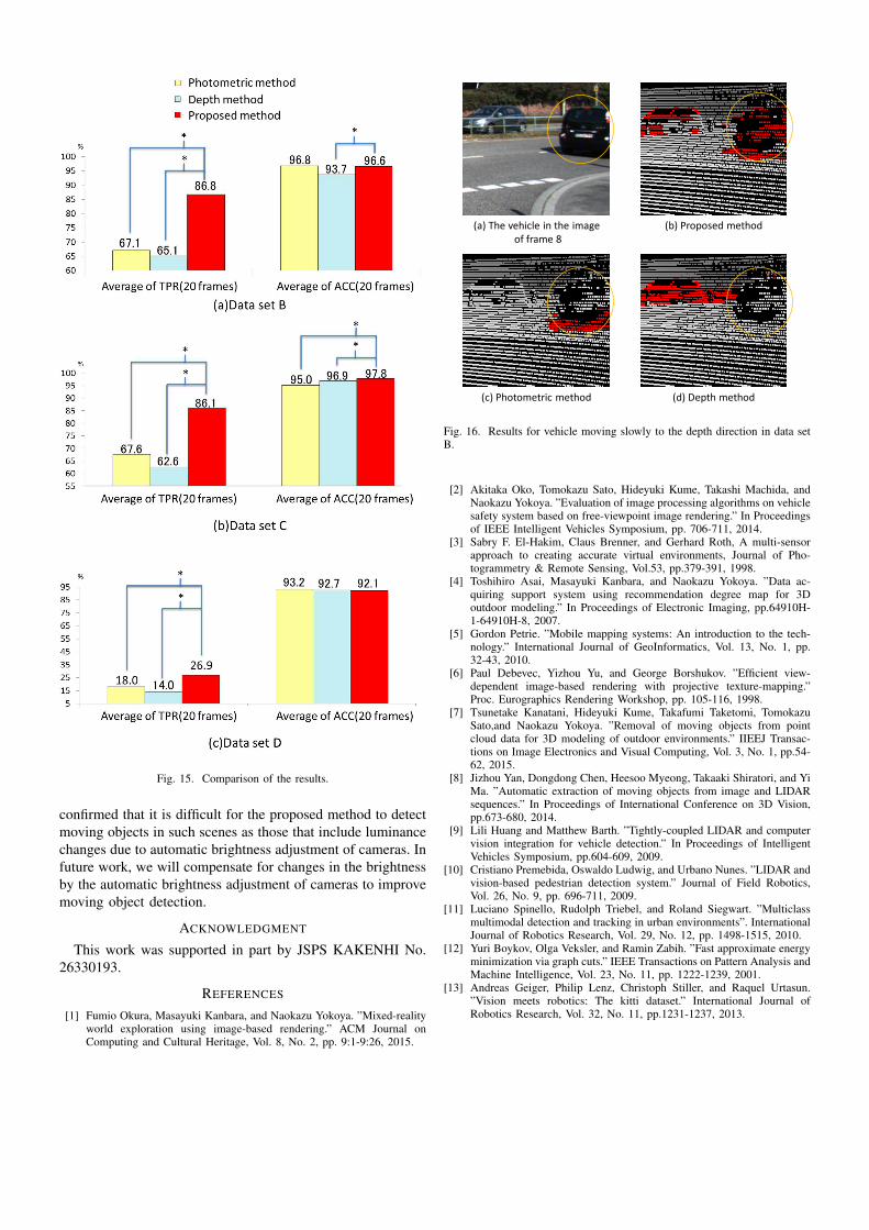
Fig. 15. Comparison of the results.
confirmed that it is difficult for the proposed method to detectmoving objects in such scenes as those that include luminancechanges due to automatic brightness adjustment of cameras. Infuture work, we will compensate for changes in the brightnessby the automatic brightness adjustment of cameras to improvemoving object detection.
ACKNOWLEDGMENT
This work was supported in part by JSPS KAKENHI No.26330193.
REFERENCES
[1] Fumio Okura, Masayuki Kanbara, and Naokazu Yokoya. ”Mixed-realityworld exploration using image-based rendering.” ACM Journal onComputing and Cultural Heritage, Vol. 8, No. 2, pp. 9:1-9:26, 2015.
(a) The vehicle in the imageof frame 8
(b) Proposed method
(c) Photometric method (d) Depth method
Fig. 16. Results for vehicle moving slowly to the depth direction in data setB.
[2] Akitaka Oko, Tomokazu Sato, Hideyuki Kume, Takashi Machida, andNaokazu Yokoya. ”Evaluation of image processing algorithms on vehiclesafety system based on free-viewpoint image rendering.” In Proceedingsof IEEE Intelligent Vehicles Symposium, pp. 706-711, 2014.
[3] Sabry F. El-Hakim, Claus Brenner, and Gerhard Roth, A multi-sensorapproach to creating accurate virtual environments, Journal of Pho-togrammetry & Remote Sensing, Vol.53, pp.379-391, 1998.
[4] Toshihiro Asai, Masayuki Kanbara, and Naokazu Yokoya. ”Data ac-quiring support system using recommendation degree map for 3Doutdoor modeling.” In Proceedings of Electronic Imaging, pp.64910H-1-64910H-8, 2007.
[5] Gordon Petrie. ”Mobile mapping systems: An introduction to the tech-nology.” International Journal of GeoInformatics, Vol. 13, No. 1, pp.32-43, 2010.
[6] Paul Debevec, Yizhou Yu, and George Borshukov. ”Efficient view-dependent image-based rendering with projective texture-mapping.”Proc. Eurographics Rendering Workshop, pp. 105-116, 1998.
[7] Tsunetake Kanatani, Hideyuki Kume, Takafumi Taketomi, TomokazuSato,and Naokazu Yokoya. ”Removal of moving objects from pointcloud data for 3D modeling of outdoor environments.” IIEEJ Transac-tions on Image Electronics and Visual Computing, Vol. 3, No. 1, pp.54-62, 2015.
[8] Jizhou Yan, Dongdong Chen, Heesoo Myeong, Takaaki Shiratori, and YiMa. ”Automatic extraction of moving objects from image and LIDARsequences.” In Proceedings of International Conference on 3D Vision,pp.673-680, 2014.
[9] Lili Huang and Matthew Barth. ”Tightly-coupled LIDAR and computervision integration for vehicle detection.” In Proceedings of IntelligentVehicles Symposium, pp.604-609, 2009.
[10] Cristiano Premebida, Oswaldo Ludwig, and Urbano Nunes. ”LIDAR andvision-based pedestrian detection system.” Journal of Field Robotics,Vol. 26, No. 9, pp. 696-711, 2009.
[11] Luciano Spinello, Rudolph Triebel, and Roland Siegwart. ”Multiclassmultimodal detection and tracking in urban environments”. InternationalJournal of Robotics Research, Vol. 29, No. 12, pp. 1498-1515, 2010.
[12] Yuri Boykov, Olga Veksler, and Ramin Zabih. ”Fast approximate energyminimization via graph cuts.” IEEE Transactions on Pattern Analysis andMachine Intelligence, Vol. 23, No. 11, pp. 1222-1239, 2001.
[13] Andreas Geiger, Philip Lenz, Christoph Stiller, and Raquel Urtasun.”Vision meets robotics: The kitti dataset.” International Journal ofRobotics Research, Vol. 32, No. 11, pp.1231-1237, 2013.