Embed Size (px)
Citation preview

SANDIA REPORT SAND96-2883 UC-705 Unlimited Release Printed December 1996
CEJVfD JAIY 1 3 f997
S T f
Moving/Deforming Mesh Techniques for Computational Fluid Dynamics and Heat Transfer
B. F. Blackwell, R. J. Cochran, R. E. Hogan, P. A. Sackinger, P. R. Schunk
Prepared by Sandia National Laboratories

Issued by Sandia National Laboratories, operated for the United States Department of Energy by Sandia Corporation. NOTICE This report was prepared as an account of work sponsored by an agency of the United States Government. Neither the United States Govern- ment nor any agency thereof, nor any of their employees, nor any of their contractors, subcontractors, or their employees, makes any warranty, express or implied, or assumes any legal liability or responsibility for the accuracy, completeness, or usefulness of any information, apparatus, prod- uct, or process disclosed, or represents that its use would not infi-inge pri- vately owned rights. Reference herein to any specific commercial product, process, or service by trade name, trademark, manufacturer, or otherwise, does not necessarily constitute or imply its endorsement, recommendation, or favoring by the United States Government, any agency thereof or any of their contractors or subcontractors. The views and opinions expressed herein do not necessarily state or reflect those of the United States Govern- ment, any agency thereof or any of their contractors.
Printed in the United States of America. This report has been reproduced directly from the best available copy.
Available to DOE and DOE contractors fram Office of Scientific and Technical Information PO Box 62 Oak Ridge, TN 37831
Prices available from (615) 576-8401, FTS 626-8401
Available to the public from National Technical Information Service US Department of Commerce 5285 Port Royal Rd Springfield, VA 22161
NTIS price codes Printed copy: A02 Microfiche copy: A01
SAND96-2883 Unlimited Release
Printed December 1996
Distribution Category UC-705
MovingDeforming Mesh Techniques for Computational Fluid Dynamics and Heat Transfer
B. E Blackwell*
R. J. Cochran
R. E. Hogan
P. A. Sackinger
P. R. Schunk
Engineering Sciences Center
Sandia National Laboratories
Albuquerque, NM 87185-0835
Abstract This report represents a summary of a Laboratory Directed Research and Development (LDRD) project to develop general purpose unstructured grid techniques for solving free and moving boundary problems in computational fluid dynamics and heat transfer. Both control volume finite element and Galerkin finite element techniques were utilized. A very robust technique for keeping the deforming mesh from tangling was implemented; the mesh was treated as a fictitious elastic body. Sample results for an ablating nose tip and buoyancy driven flow in a box are presented. References to additional publications resulting from this work are included.
* Authors are in alphabetical order.

Portions of this document may be illegible in electronic image products. Images are produced from the best available original dOCUment.

DISCLAIMER
This report was prepared as an account of work sponsored by an agency of the United States Government Neither the United States Government nor any agency thereof, nor any of their employees, makes any warranty, express or implied, or assumes any legal liability or responsibility for the accuracy, completeness, or use- fulness of any information, apparatus, product, or process disclosed, or represents that its use would not infringe privately owned rights. Reference herein to any spe- cific commercial product, process, or service by trade name, trademark, manufac- turer, or otherwise does not necessarily constitute or imply its endorsement, recom- mendation, or favoring by the United States Government or any agency thereof. The views and opinions of authors expressed herein do not necessarily state or reflect those of the United States Government or any agency thereof.

MovingDeforming Mesh Techniques for Computational Fluid Dynamics and Heat Transfer
Introduction Numerous important fluid and thermal phenomena exist in which the shape of an object or the location of an interface between dissimilar materials and/or phases is an unknown part of the solu- tion. An example of this kind of phenomena occurs during the manufacture of advanced inte- grated circuit devices using Chemical Vapor Deposition (CVD). During this process, deposition takes place on a small (micron size) trench, which is shown schematically in Figure 1. As the pro-
ct Reactive Molecules rp Vapor Phase
J Shape Thin Film a
Figure 1 : Schematic of thin film deposition process; a prototype MB problem.
file shape evolves with time, it alters the rate at which reactive molecules strike the surface, par- ticularly in the trench. Consequently, the computational mesh for both the vapor phase and solid substrate must account for the growth of the thin film. In addition to the field variables of veloc- ity, temperature, density, pressure, specie concentration, etc., the shape of the interface between these two regions is also an unknown. The profile shape determines how long the device must stay in the CVD reactor. Problems like the CVD reactor belong to a general class of problems involvingfree and moving boundaries. These problems pose a particular challenge to the methods and techniques of computational physics (Crank [7], Finlayson [SI), since the problems are so dif- ficult that approximate numerical solutions are frequently the only recourse available to the ana- lyst. Other examples of free boundary (FB) and moving boundary (MB) problems include solidification of castings, solders, and semiconductors, extrusion of metals and polymers, coating flows, sol-gel processing, mold filling, seepage flow under an earthen dam, and ablation of reen- try bodies.
Of the many possible approaches to computational simulation of FB and MB problems, the thrust of our research was oriented towards deformable grid techniques in which the unknown interface shape govern the distribution of the grid in the continuum phases- the discretized grid matches the boundary shape precisely. This is in contrast to fixed-grid volume tracking techniques such as marker-and-cell (MAC) (Harlow and Welch [9]), or volume of fluid (VOF) (Hirt, et a1 [lo])
1

app:roaches to simulating continuum phases with free or moving boundaries. Figure 2 illustrates FIXED GRID
DEFORMABLE GRID
Figure 2: Fixed-grid, volume tracking approach vs. deformable grid approach.
the fundamental difference between the two approaches. Generally, the fixed grid approach suf- fers more imprecision in the representation of the interface position, slope and curvature and in the application of boundary conditions at the interface than the deformable grid approach, but, admuttedly, offering a greater ability for solving problems with severe changes in the topology of the iinterface. The distinguishing physics that governs the shape of a free boundary typically involves field variables such as concentration, temperature, or velocity or derivatives of these variables at the unknown FB or MB interface, giving an advantage to methods which conform the grid precisely onto the interface. Changes in the kind and number of governing continuum equa- tions across free or moving interfaces are more easily incorporated into simulations if there are no partially-filled cells with which to contend. For problems where the mesh continuously evolves in time (e.g., moving boundary problems), additional convective terms appear in the bulk conserva- tion equations that express the apparent flux contributions due to the relative motion between the material and the mesh. For the fluid and thermal problems that are the focus of this research, these addit tional terms are easily incorporated into the computational algorithm.
The objective of this research was to investigate and develop accurate techniques for solving free and moving boundary problems on deformable grids. The principal challenge to overcome was devi sing robust procedures for propagating the boundary and interface deformations into the inteirnal portions of the computational domain.
Mesh MotiodDeformation Strategies
Previously-developed computational techniques for solving free and moving boundary problems using deforming or moving grids have often relied upon the grid structure in order to provide a convenient mechanism for repositioning the internal grid points in response to the deforming interface. The method of spines represents one of the techniques for tying the deformation of the internal mesh to that of the interface. In their simplest manifestation, spines represent guiding lines to which the internal mesh is constrained. A more sophisticated example of spines is shown in Figure 2, where the heat conduction equation is solved for the interior of an axisymmetric reen-
2

try body as the exterior surface ablates. The grid presented here was constructed by di
3
2
1
n - 0 1 2 3 4 5
z, cm Figure 3: Initial “spine” type mesh for reentry body
6
viding the
mesh into two regions; an inner fixed mesh region and an outer movi g mesh region. It is antici- pated that ablation will not proceed past the interface between the two regions. The moving region was constructed by defining a series of kinked spines that are approximately normal to the initial ablating surface and the nodes in the moving region are regularly structured (i.e,, a two- component Cartesian product (i,j) indexing scheme addresses every node). Moving nodes are constrained to move along their respective spine. The surface nodes move in response to the com- puted recession rate (determined from surface energy balance) while the nodes at the interface between the two regions remain fixed. Interior nodes (for a given spine) have displacements that are intermediate between the surface displacement and zero displacement of the interface nodes, depending on the arc length along the spine. Although the spine approach produces acceptable results and is computationally efficient, it does suffer from some distinct disadvantages:
A structured grid is required for the deforming or moving region. The approximate shape of the free or moving boundary must be gauged in advance so that spines may be prescribed which avoid becoming tangent to the boundary.
The emphasis of this work was to develop techniques that would eliminate the above disadvantag- es. Lynch and O’Neill [ 13 proposed that the mesh displacement for two dimensional domains be computed as if the mesh region was a fictitious elastic body undergoing plane stress deformation. For the ablating nose tip example, the ablating surface boundary conditions would be a specified displacement as computed from the surface energy balance. Along any interface between the fixed and moving regions, zero displacement is specified, just as for spines. For the remaining two boundaries, nodes are constrained to move freely along those boundaries with no imposed tangen- tial traction. Only the moving mesh region will be treated as a fictitious elastic body, since by def- inition the fixed mesh region does not move. Using the concept of a fictitious elastic continuum places no restrictions on the underlying grid structure. Indeed, a long history of accumulated evidence has shown the practicality of using un-
3

structured finite element meshes in two and three dimensions for solving elasticity problems in ar- bitrary complex geometries. Additionally, automatic mesh generation may be used to discretize the: initial shape of the computational domain for the free or moving boundary problem. For the work presented here, the small displacement form of the linear, isotropic equations of elasticity were utilized. This constitutive model was chosen simply for convenience, other choices might perform as well or even better than this simple model. However, the mechanical response of the fictitious solid is not the central focus of our effort; only the integrity of the deforming mesh is important insofar as the FB or MB problem is concerned. In the linear elastic model, two material parameters are sufficient to completely describe the inter- nal response of the fictitious solid: Poisson’s ratio and Young’s modulus are two such parameters. One might ask how one chooses values for these parameters that will produce satisfactory grid de- formation. Some guidance can be obtained by looking at the one-dimensional form of the equa- tions of elasticity. In this case, Young’s modulus is the only material property required. For displacement boundary conditions. the interior nodal displacement is a linear function of position and is independent of Young’s mtdulus. The resulting stresses are directly proportional to Yonng’s modulus. However. sincc we are not Concerned with stresses but only with using the equations of elasticity to movc thc mesh in response to specified surface displacements, Young’s modulus is arbitrary for one-dimcnsional problems. For multi-dimensional problcms. hoth Young’s modulus (E) and Poisson’s ratio (v) may be re- quired material parameters. For thc special case of a homogeneous and isotropic material with constant properties and no body forces present, Young’s modulus cancels out of the governing partial differential equations for thc displacement field. As long as the boundary conditions in- volve only displacements and not forces, then the displacement field will be independent of Young’s modulus. However, Poisson‘s ratio still appears in the governing partial differential equa- tion and will have an impact o n how the mesh moves. Physically, Poisson’s ratio is the ratio of lat- erall to longitudinal strains. Conscqucntly, it is expected that Poisson’s ratio will have an impact on how interior node points movc for a prescribed boundary displacement because a longitudinal contraction is accompanied hy a lateral extension. The incompressibility limit occurs at Poisson’s ratio of 0.5. There are many reasons to avoid thc incompressible limit at v=0.5. Probably the most important reason for avoiding an incomprcssiblc pseudo-solid material for the mesh is that most free and moving boundary problems require a mesh with an overall volume that changes from its initial value. Secondly, much more specialized finite element formulations are required for strictly in- compressible materials as compared to compressible solids. Indeed, if values of v approaching the incompressible limit of 0.5 arc used, such as 0.495, then anomalous behavior of the mesh can re- sult. The: original work by Lynch and O’Neill [ 11 possessed several important features, some of which we modified in our investigations. Lynch and O’Neill focussed on using finite element techniques for moving boundary problems. They proposed an algorithm based on time-marching both the governing conservation equations (e.g., the energy equation in case of solidification problems) and the linear equations of elasto-statics. The latter equations are solved on the initial undeformed gridl for the displacements of all the interior nodes of the mesh required to satisfy the boundary distortions induced by the distinguishing physics at the boundary. Two variations on this approach were developed in the course of our researches.
4

First, a control volume finite element (CVFEM) approach was developed which enabled the anal- ysis of problems using the power of unstructured grid generators. Initially, the CVFEM approach relied on combining a spine-based approach and structured mesh in the region adjacent to the moving boundary, and a fixed, unstructured grid comprising a core region of the computational domain. In later work, the unstructured grid was extended to include the entire computational do- main, demonstrating the generality of the approach. In a second thrust of the project, an implicit approach to the finite element formulation was taken, in which all of the equations, including the mesh displacement equations, were solved on the de- formed domain. A global Newton-Raphson iteration scheme was chosen to solve the resulting set of coupled nonlinear equations resulting from the finite element discretization. Among other ad- vantages [5] , this provided a mechanism for solving free boundary problems as well as moving boundary problems in which the distinguishing conditions are implicit (i.e., not explicit functions of boundary position or velocity). A variety of problems [6] in capillary hydrodynamics that are normally quite difficult to solve in regimes where surface tension and viscous effects are both im- portant were solved using this approach.
Sample Results Thermal Ablation Problem Using CVF'EM Method Representative computational results for an ablating graphite nose tip problem are shown in Fig- ure 3. The mesh motion equations and the energy equation were solved in a fully coupled but seg-
3
T in K E 0 z
2
1
n " 0 1 2 3 4 5 6
z, cm Figure 4: Representative temperature contours and nose shape using Elastic Mesh Motion Algorithm
regated manner. Although the outer mesh is structured in appearance, the analysis code treated it as if it were unstructured. The fictitious mesh material properties used for this analysis were those of steel. The deformed mesh appears to remain of high quality. Additional details can be found in [2] and [4]. Computational experiments have indicated that the Elastic Mesh Motion Algorithm takes roughly 2.5 times the computational time as the corresponding spine algorithm for this problem. Because of the increased flexibility and generality, this increased computational time should be more than
5

offset by a reduction in the analysts time.
Newton-Raphson Implicit Mapping Hydrodynamic Problem Figures 4-5 show a sequence of the initial mesh, deformed mesh, temperature fringes and velocity
6
Slde heated buoyancy-driven sheer-free box w / DC T=O on mldplane hiflai Undeformed Meah
Slde heafed buoyancy-&ken shear-free box w / DC T=O on mldplane Flnal Deformed Mesh
Figure 4: Sample free boundary problem of buoyancy-driven convection in a shear-free box with insulated top and bottom and isothermal walls. (a) The initial guess with undeformed mesh and thermal conduction across box. (b) The final de- formed mesh with distinguished isotherm distorted by convection.
vectors, respectively for a contrived free boundary problem that incorporates the needed ingredi- ents for solving many steady solidification problems. The problem is of buoyancy-driven convec- tion in a square box with shear-free sides, insulated on top and bottom, and with specified temperatures T= +/- 3 on the vertical walls. The isotherm T=O was distinguished as an internal
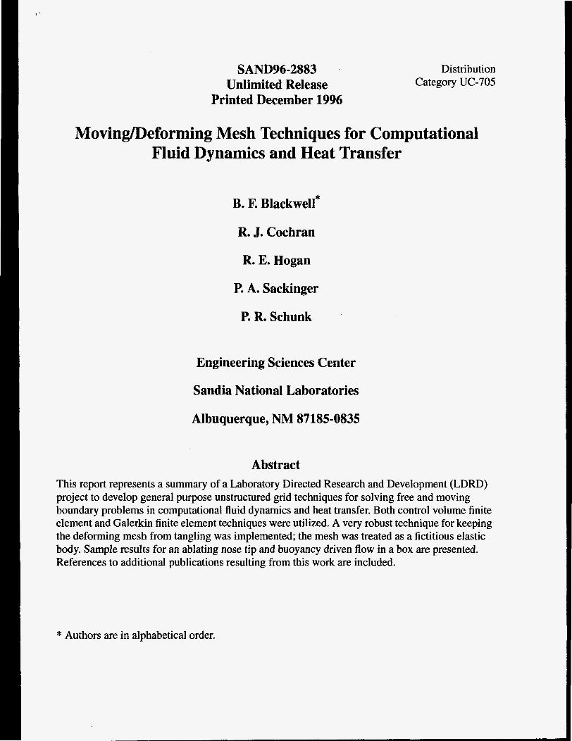
free boundary to which the deforming mesh had to conform. The solution shown in Figure 5 is for
Slde heated buoyancy-driven shear-free box w/ DC T=O on midplane Temparafure
Stde heated buoyancy-drlvsn rhsar-free box w/ DC T=O on mldpbns Vsloclfy v d o r s
Figure 5: Sample free boundary problem of buoyancy-driven convection in a shear-free box with insulated top and bottom and isothermal walls. (a) Tempera- ture fringe plot on the deformed mesh; internal boundary T=O is distinguished.
(b) Velocity vectors.
a buoyancy force corresponding to a Grashof number of 4 and a thermal Peclet number of 20. The distinguished isotherm assumes a characteristic bent shape as the convective heat transfer be- comes more important relative to conduction. These solutions were obtained in 3 to 5 Newton it- erations from the initial guess. Some care must be taken in the choice of initial guess. In this case, a conduction solution of the heat equation in a fixed box was used as an initial guess. The algorithm has difficulty converging if an initial guess of T=O everywhere is used: there is no temperature gradient to which the New- ton iteration can adjust the initial guess of the T=O isotherm position. This restriction on initial guess is not a severe one; however, it does indicate that some intuition and common sense is re- quired of the analyst to use this algorithm for various FB and MB problems. Again, while this particular example shows a structured mesh (Figures 4 and 5), other problems with more physical relevance have been solved using unstructured meshes that can better adapt to efficiently resolving local features of the solution. Further examples showing the utility of this ap- proach may be found in the [5 ,6 ] .
Summary Useful approaches to the numerical simulation of free and moving boundary problems have been developed as a consequence of this research. For applications in which the topology of the com- putational domain does not change drastically and where an accurate representation of the bound- ary or interface shape is important, the extended techniques based on a fictitious solid material to
7

adjust the internal mesh have a demonstrable value in our ability to simulate many important prac- tical problems involving free and moving boundaries. The examples shown in the references [2-6] that are an outgrowth of this research attest to the power and generality of the technique. We be- lieve that the prototype demonstrations shown here and in the references provide sufficient evi- dence of proof-of-concept to warrant further work in this area towards developing a more general capability.
References 1. ]Lynch, D. R. and O’Neill, K., “Elastic Grid Deformation for Moving Boundary Problems in
‘Two Space Dimensions,” Finite Elements in Water Resources 111, Wang, et. al., Eds., pp. ’7.1 11-7.120, University of Mississippi-Oxford, 1980.
2. IBlackwell, B. F., Thornton, A. L. and Hogan, R. E., “Ablation Problems Using a Finite Con- trol Volume Technique,” Proceedings of the Moving Boundary 93 Conference, Milan, Italy, pp. 295-302, June 1993.
3. Schunk, P. R., Sackinger, P. A., Hogan, R. E., and Blackwell, B. F., oral presentation at the 7th 1:nternational Coating Process Science and Technology Symposium, AIChE 1994 Spring Na- tional Meeting, Atlanta, GA, April 17-21, 1994.
4. Hogan, R. E., Blackwell, B. F., and Cochran, R. J., “Numerical Solution of Two-Dimensional Ablation Problems Using the Finite Control Volume Method with Unstructured Grids,” AIAA 94-2085, presented at 6th AIANASME Joint Thermophysics and Heat Transfer Conference, June 20-23, 1994, Colorado Springs, CO.
5. Sackinger, P. A., Schunk, P. R., and Rao, R. R.,”A Newton-Raphson Pseudo-Solid Domain Mapping Technique for Free and Moving Boundary Problems: A Finite Element Implementa- tion,” submitted to J. Comp. Phy., 1995.
6. Chen, K. S., Schunk, P. R., and Sackinger, P. A., “Finite Element Analyses of Blade and Slot Coating Flows using an Implicit Pseudo-Solid Domain Mapping Technique Coupled with Un- structured Grids,” to appear in Proceedings of the TAPPI Third Coating Fundamentals Sym- posium, 1995.
7. Crank, J., Free and Moving Boundary Problems, Oxford, 1984. 8. Finlayson, B. A., Numerical Methods for Problems with Moving Fronts, Ravenna Park, 1992. 9. Francis H. Harlow and J. Eddie Welch, “Numerical Calculation of Time-Dependent Viscous
Incompressible Flow of Fluid with Free Surface,” Physics of Fluids, volume 8, number 12, pp 2182-2189, 1965.
10. (1. W. Hirt and B. D. Nichols, “Volume of Fluid (VOF) Method for the Dynamics of Free Ijoundaries,” J. Computational Physics, 39,201-225, 1981.
8

Distribution 1 1 1 1 1 5 5 1 1 1 1 1 1 5 5 1 1 1 5 2 3 1 1
MS-0188 MS-0437 MS-0443 MS-0825 MS-0826 MS-0826 MS -08 26 MS-0827 MS-0828 MS-0828 MS-0833 MS-0834 MS-0835 MS-0835 MS-0835 MS-0836 MS-084 1 MS-90 18 MS-0899 MS-06 19 MS-0161 DOEEE-3 2 DOEEE-222
C. E. Meyers R. K. Thomas H. S. Morgan W. H. Rutledge S. N. Kempka P. A. Sachnger P. R. Schunk A. S . Geller E. D. Gorham R. D. Skocypec J. H. Biffle A. C. Ratzel T. C. Bickel B. E Blackwell R. J. Cochran C. W. Peterson P. J. Hommert Central Technical Files, 8523-2 Technical Library, 4414 Review & Approval Desk, 12630 for DOE/OSTI Patents and Licensing Office, 11500 T. G. Marachaux S. Dillich


![Variational Autoencoders for Deforming 3D Mesh Modelshumanmotion.ict.ac.cn/papers/2018P5_Variational...formations, along with a variational autoencoder [19]. To cope with meshes of](https://img.pdfslide.net/doc/110x75/5ec60816df097e0643499b16/variational-autoencoders-for-deforming-3d-mesh-formations-along-with-a-variational.jpg)