Embed Size (px)
Citation preview

MPC MULTIPROTOCOL DDC CONTROLSApplication, Operation & Maintenance
97B0031N01Revised: March 7, 2017
THE SMART SOLUTION FOR ENERGY EFFICIENCY
MPC MultiProtoCol DDC ControlsR e v i s e d : M a r c h 7 , 2 0 1 7
2
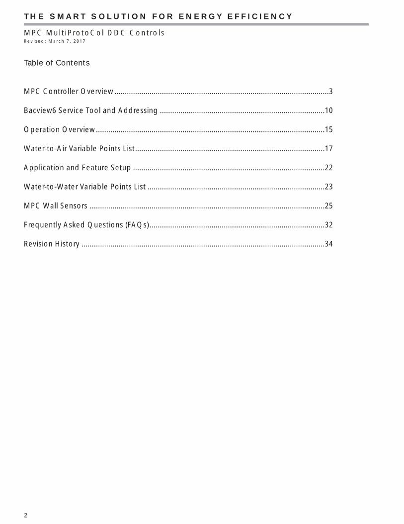
Table of Contents
MPC Controller Overview ........................................................................................................3
Bacview6 Service Tool and Addressing ................................................................................10
Operation Overview ...............................................................................................................15
Water-to-Air Variable Points List ............................................................................................17
Application and Feature Setup .............................................................................................22
Water-to-Water Variable Points List ......................................................................................23
MPC Wall Sensors ..................................................................................................................25
Frequently Asked Questions (FAQs) .....................................................................................32
Revision History ......................................................................................................................34

THE SMART SOLUTION FOR ENERGY EFFICIENCY
MPC MultiProtoCol DDC ControlsR e v i s e d : M a r c h 7 , 2 0 1 7
3
The MultiProtoCol (MPC) Heat Pump controller is a dual purpose controller: it contains the logic to perform as an advanced customizable thermostat when combined with a wall sensor and is designed to allow the integration of water source heat pump equipment into DDC systems. The MPC Controller has the ability to communicate through a choice of four widely used protocols: BACnet MS/TP, Johnson Controls N2, and Modbus and LonWorks. The protocol of choice for the particular system is selected by simply confi guring DIP switches on the MPC Controller with the exception of LonWorks. The LonWorks option requires an additional Lon option card (LOC). This fl exibility allows one controller, the MPC, to be used in a multitude of buildings which use any of these four common protocols.
The MPC serves as a node of information processing between the heat pump and the DDC network. The MPC commands the heat pump to heat and cool based upon sensor inputs. The MPC then monitors operation of the heat pump and communicates the operating parameters to the DDC network. The MPC will alwayswork in conjunction with a CXM, DXM or DXM2 controller, which also resides in the heat pump control box. The MPC has factory pre-loaded application software which allows optimal control of the heat pump equipment. The MPC can run in stand-alone operation as well as with the DDC network. Therefore, when the heat pump arrives at the jobsite with the factory installed MPC Controller, the heat pump is ready to run stand-alone and then can be connected to the DDC network at any time.
Features & BenefitsSystem Controls: In conjunction with the wall sensors, the MPC offers features such as:
• Room temperature sensing• Local setpoint adjustment• Local override into Occupied Mode• LED for alarm status• LED for fault status type• Heat pump reset at the wall sensor• Digital room temperature display• Information from the wall sensors can then be reported to the DDC network system.• Has the ability to add various sensors such as occupancy sensors.
Communications: Multi-Protocol communications provides DDC system flexibility.
• Supports native BACnet MS/TP communications (the ASHRAE standard protocol for interoperability).
• Supports Johnson Controls N2 communications (for integration into Johnson Controls Metasys
• DDC systems).• Supports Modbus communications for integration into
Modbus DDC networks.• Supports LonWorks communications. Requires LOC
daughter card (PN-17B0012N08• Four baud rate levels offer flexible communications
speeds of 9600, 19.2k, 38.4k, or 76.8k baud.• High speed 16-bit Hitachi Processor with 1024 kBytes
RAM and 4096 kBytes Flash Memory which allows, if needed, MPC programs to be upgraded and easily downloaded in the field.
• Removable field wiring connectors for ease of field service.
• Engineered for quality and reliability• Enables building operators to easily upgrade firmware
in the future.
MPC Controller Overview

THE SMART SOLUTION FOR ENERGY EFFICIENCY
MPC MultiProtoCol DDC ControlsR e v i s e d : M a r c h 7 , 2 0 1 7
4

THE SMART SOLUTION FOR ENERGY EFFICIENCY
MPC MultiProtoCol DDC ControlsR e v i s e d : M a r c h 7 , 2 0 1 7
5
Power: 24VAC ± 10%, 50 or 60Hz, 15VA max. power consumption.
Size: 5-1/16” [129mm] width x 5-11/16” [144mm] height x 1-1/2” [38mm] (minimum panel depth).
Housing: Rugged GE C2905HG Cycoloy plastic housing (complies with UL 94 V-O).
Environmental: 0-130°F (-17.8 to 54.4 °C), 10% to 95% non-condensing.
Protection: Surge & transient protection circuitry for the power and I/O. Optical isolation for communications port.
Processor/Memory: High speed 16-bit Hitachi Processor with 1024kB RAM and 4096kB Flash Memory.
LED Indicators: Individual LEDs for digital outputs, power, run, error, transmit, and receive.
Compliance: UL916; FCC Part 15, Subpart B, Class A; ICES, Class A; EN55022, Class A; IEC61000-6-1; RoHS complaint, WEEE Complaint; BTL listed
I/O Point Count: 5 digital outputs (on-board relays rated for 1A resistive at 24VAC). 6 universal inputs (IN-1 and IN-2 are jumper selectable for dry contact or 0-5VDC). 1 analog wall sensor port for non-communicating (Lstat) wall sensors. 1 digital wall sensor port for communicating (Rnet) wall sensors.
Communications: EIA-485 communications port using twisted pair. A two position DIP switch allows for manual selection of desired protocol. Available protocols are BACnet MS/TP, Johnson Controls N2, Modbus and LonWorks (requires Loc daughter card. Another 2 position DIP switch allows for manual selection of desired baud rate. Available baud rates are 9600, 19.2k, 38.4k, and 76.8k.
Addressing: 2 rotary switches are provided for setting the individual controller’s primary network address (for more information on network addressing, see Addressing & Power Up).
Wall Sensor: The wall sensors provide room temperature sensing with digital display, local setpoint adjust, local override, LED for alarm status and fault type indication, and heat pump reset. The wall sensors require a 4 wire connection for communication or 5 wire connection for non-communicating.
Mounting Hole Two mounting holes center line as below with 5-9/16 ” [141mm] height spacing. Dimensions: Factory mounted.

THE SMART SOLUTION FOR ENERGY EFFICIENCY
MPC MultiProtoCol DDC ControlsR e v i s e d : M a r c h 7 , 2 0 1 7
6
Module Hardware Addressing
Communications
Local Access Port
(Communicating) Rnet Sensor
(Non-CommunicatingLStat Sensor
Connector
Communications Type Selection
Physical Dimension: 5.88" (149.4mm) x 5.66" (143.8mm)
Room Sensor Type Selection
GainJumper
24VacConnector
Protocol & Baud Rate
Output LED’s
IN-1*
IN-2**
Inputs1-4
LonWorks Daughter Card Connection
Outputs

THE SMART SOLUTION FOR ENERGY EFFICIENCY
MPC MultiProtoCol DDC ControlsR e v i s e d : M a r c h 7 , 2 0 1 7
7
Factory Use Only - 1Default = no jumper
Selects “LSTAT Sensor Connection” or “RNET” port as the active port for room sensor. Default = LSTAT
Factory Use Only - 2Default = jumpered
Selects 1x (jumpered) or 3x (no jumper) gain for “Therm” Input. Default = 3x (no jumper)
Selects “Thermistor/Dry contact or “0 to 5Vdc” input for IN-1Default = “Thermistor/Dry Contact”
Selects “Thermistor/Dry contact or “0 to 5Vdc” input for IN-2Default = “Thermistor/Dry Contact”
Selects “RS-485 MS/TP” or “ARC156”Default = “RS-485 MS/TP”

THE SMART SOLUTION FOR ENERGY EFFICIENCY
MPC MultiProtoCol DDC ControlsR e v i s e d : M a r c h 7 , 2 0 1 7
8
Communications SelectionWhen the Communications Selection Jumper is in the “BACnet over ARC156” position, DIP switch selectors SW1, SW2, SW3, and SW4 are all disabled. When the Communications Selection Jumper is in the “BACnet over ARC156” position, BACnet protocol is selected and the baud rate is also selected to be 156 kbps. In this scenario, when the comm. port is confi gured for “BACnet over ARC156” communications, use an A3ARC156 wire available from:
When the comm. port is confi gured for RS-485 communications, use standard dedicated 22AWG- 18AWG twisted pair wire.
For complete details on wiring, termination, and ngfor BACnet MS/TP, refer to ANSI/ASHRAE 135-1995, clause 9.2.2. Refer to the Application Note for the BACnet devices that you will be interfacing with for specifi c wiring.
Communications Wiring Instructions1. Be sure the module’s power is off before wiring it to the ARC156 or RS-485 communications bus.2. Check the network communication wiring for shorts and grounds.3. Connect the ARC156 or RS-485 wires and shield to the module’s screw terminals as shown in Figure 9. Be sure to follow the same polarity as the rest of the ARC156 or RS-485 communications network.4. Power up the module.5. Proper communications for all protocols and baud rates can be verifi ed by making sure the transmit (Tx) and receive (Rx) LEDs are active.
Protocol Confi gureThe comm. port on the MPC has MultiProtoCol capability which means the MPC can be confi gured to communicate via BACnet, Johnson Controls N2, or ModBus communication protocols. This confi guration is done via the “Communications Selection” jumper and the 4-position DIP switch package (SW1, SW2, SW3, SW4) located on the MPC. The comm. port’s baud rate is also set with this same 4-position DIP switch package. See Figure 9 below.
Note: If using ARC156 wiring, then only BACnet protocol can be used. When using RS-485 wiring, any of the 3 protocols (BACnet, N2, ModBus) can be used.
Figure 9: Wiring the ARC156

THE SMART SOLUTION FOR ENERGY EFFICIENCY
MPC MultiProtoCol DDC ControlsR e v i s e d : M a r c h 7 , 2 0 1 7
9
BACnet Setup – The MPC can be set up to communicate via “BACnet over ARC156” or “BACnet MS/TP”. Refer to Table 2 for setup.
N2 Setup – N2 must be confi gured for RS-485 communications with a baud rate of 9600, using 8 data bits, no parity, and 1 stop bit. The MPC is always an N2 slave. Refer to Table 2 for setup.
ModBus Setup – ModBus must be confi gured for RS-485 communications. Baud rate can be selected from 38.4 kbps, 19.2 kbps, or 9.6 kbps. Refer to Table 2 for setup.
Figure 10: Communications Selections
Table 2: Communications Set Up

THE SMART SOLUTION FOR ENERGY EFFICIENCY
MPC MultiProtoCol DDC ControlsR e v i s e d : M a r c h 7 , 2 0 1 7
10
BACview6 Service Tool
BACview6 provides local access to control and operational properties of equipment. The BACview6 simply plugs into an Rnet connection (local access port) and allows you to display and modify Climate Master-defi ned properties without any computer software. The BACview6 features a numeric keypad, directional keys, and four function keys. A large 4-line by 40-character backlit LCD display is provided for easy reading even in poor lighting conditions. The device also includes an alarm indicator light and audible warning. ClimateMaster recommends this service tool for sites over 25 units or units with the stand-alone application.Part#1: ABACVIEW6Part#2: ABACVIEW6A (cable)
HOW TO WIRE ABACVIEW to ABACVIEW6A
When prompt for password.ClimateMaster Password: 1111
Red Blue
White Black&Green
12vRnet-Rnet+GND

THE SMART SOLUTION FOR ENERGY EFFICIENCY
MPC MultiProtoCol DDC ControlsR e v i s e d : M a r c h 7 , 2 0 1 7
11
Before setting or changing the module's hardware address, make sure the MPC Controller power is off. The MPC only reads the address when the module is turned on. The MPC has two rotary switches for assigning the module’s hardware address. One switch corresponds to the “tens” digit and the second switch corresponds to the “ones” digit, allowing for hardware- based address-ing of up to address 99. For example, if the module’s address is three, set the tens switch to zero and the ones switch to three. The station ID for each MS/TP node must be unique on a MS/TP segment. The MPC’s rotary address switches are used to set this unique ID.
Addressing & Power Up
Changing the device instance when using a network of more than 99 MPC units
Note – This applies to Gen4 MPC’s only. When using Gen3 MPC’s, to allow for more than 99 unique addresses, a special request should be made through the Product Management and Applications team.
The Gen 4, 5 and 6 MPC allows the device instance to be changed using the BACview6 service tool. This fea-ture allows an installation with more than 99 MPC-based units to be set and managed on-site rather than factory preset.
In order to change the device instance, the MPC must be powered up. Connect the BACview6 service tool to the MPC using the local access port. When the main screen appears, scroll down to “Manual Control” using the down arrow and press “Enter”;
At the “Manual Control” screen, press “Enter” with “Unit Confi guration” highlighted and again with “BAC- net” highlighted. The following screen should appear;
1
Setting Module Address
NOTE: Set address for heat pump #1 (HP-1) at 02 per typical BMS naming conventions. All other heat pump addresses should be assigned as HP# + 1.
After setting the address, turn power on to the MPC. The Run, Error, and Power LEDs should turn on. The Run LED should begin to blink and the Error LED should turn off. Use Table 1 to troubleshoot the LEDs.

THE SMART SOLUTION FOR ENERGY EFFICIENCY
MPC MultiProtoCol DDC ControlsR e v i s e d : M a r c h 7 , 2 0 1 7
12
Addressing & Power Up
The device instance is typically six digits long. The last two digits correspond to the hardware’s module address so these should not be changed using the BACview6
To change the device instance, use the down arrow to highlight the numbers beside “Base BACnet Device ID” and press “Enter”. You will be prompted for an Admin Password, the password is 1111. A cursor underlining the fi nal digit of the “Base BACnet Device ID” will appear.
Before change (fourth digit is 0);
2 3
4
THE SMART SOLUTION FOR ENERGY EFFICIENCY
MPC MultiProtoCol DDC ControlsR e v i s e d : M a r c h 7 , 2 0 1 7
13
The MPC Controller has the following LEDs:Power - indicates when power is on.Run - blinks when the processor is running. Error - lights when an error is detected.Receive (Rx) - lights when the Comm Port receives data. Transmit (Tx) - lights when the Comm Port transmits data. Digital Output - lights when the associated digital output turns on.
LED Power-Up SequenceDuring power-up, the module goes through an initialization and self test sequence.
Proper module power-up can be verifi ed by observing the LEDs as follows:1. The Run and Error LEDs turn on and begin blinking.2. The Error LED then turns off.3. The Run LED continues blinking.
Note: The Error LED fl ashes three times in sync with the Run LED when the module is being formatted. The Run LED should never stop fl ashing. If it stops fl ashing for 1.5 seconds, the watchdog timer will reset the module.
Overcurrent ProtectionThe MPC Controller is protected by internal solid state polyswitches (polymeric PTC, resettable overcurrent protection device, also called PPTC) on the incoming power. The overcurrent protection circuitry is a positive temperature coeffi cient (PTC) thermistor that increases in resistance as it warms up and stays in that mode until the power is removed. Once the power is removed, the polyswitch resistance lowers to operational level as the device cools down. After power has been re-applied, the unit will operate properly if the fault condition has been removed.
It is not necessary to remove power on the communication line in order to reset the solid state overcurrent circuit. Once the power level is low enough, the overcurrent circuit cools down to operating temperature. A blown polyswitch can indicate incorrect wiring if the polyswitch is blown during installation.Generally, a blown polyswitch indicates a power surge was received by the board.
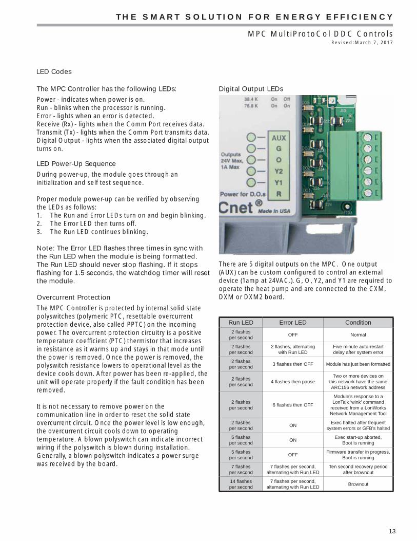
Digital Output LEDs
There are 5 digital outputs on the MPC. One output (AUX) can be custom confi gured to control an external device (1amp at 24VAC.). G, O, Y2, and Y1 are required to operate the heat pump and are connected to the CXM, DXM or DXM2 board.
Run LED Error LED Condition
2 fl ashes per second
OFF Normal
2 fl ashes per second
2 fl ashes, alternating with Run LED
Five minute auto-restart delay after system error
2 fl ashes per second
3 fl ashes then OFF Module has just been formatted
2 fl ashes per second
4 fl ashes then pauseTwo or more devices on
this network have the same ARC156 network address
2 fl ashes per second
6 fl ashes then OFF
Module’s response to a LonTalk ‘wink’ command
received from a LonWorks Network Management Tool
2 fl ashes per second
ONExec halted after frequent
system errors or GFB’s halted
5 fl ashes per second
ONExec start-up aborted,
Boot is running
5 fl ashes per second
OFFFirmware transfer in progress,
Boot is running
7 fl ashes per second
7 fl ashes per second, alternating with Run LED
Ten second recovery period after brownout
14 fl ashes per second
7 fl ashes per second, alternating with Run LED
Brownout
LED Codes

THE SMART SOLUTION FOR ENERGY EFFICIENCY
MPC MultiProtoCol DDC ControlsR e v i s e d : M a r c h 7 , 2 0 1 7
14
Room Sensors
The MPC is design to work with specifi c sensors. Two types of sensors may be used: Lstat (ASW06, ASW07, and ASW08) and RNet (ASW13, ASW14, and ASW15). The RNet connection is at the upper left of the MPC and the LSat is at the lower left. Both are four to fi ve wire sensors. The MPC comes factory set for the Lstat sensor at the room sensor jumper. To utilize the RNet (ASW13, 14, 15) sensors the jumper must be changed to RNet.
The use of the RNet sensor allows for an extra input into the MPC. The ASW13, 14 15 are available with additional internal sensors possibilities including Humidity, CO2 or VOC. When using a unit equipped with Climadry Reheat, a combination temperature and humidity sensor is required. Refer to ASW section.
Additional Inputs
There are four inputs available when either type of sensor is used. Two additional inputs are available when the Rnet sensor is used.
AL1/AL2 and EH2 input terminals can accept 0-5VDC, Thermistor, or dry contact signals. Terminals LAT/LWTL and LWT/LWTS accept thermistor or dry contact signals.
LAT/LWTL and LWT/LWTS come with leaving air and leaving water temperature thermistors installed but can be repurposed. The Lsat terminals can be used for an additional thermistor input (Gnd/Temp) and SW can be used as a dry input contact.
The MPC allows custom programing of the various inputs to accomplish various sequence of operations as the building may require. A common use could be an occupancy sensor which can put units in a standby mode.
Certain options can be added to the MPC programing after installation if controls system upgrades/changes are being considered. Consult factory for applicability. The MPC can be programmed with a 7 day program: the routine is built into the software.

THE SMART SOLUTION FOR ENERGY EFFICIENCY
MPC MultiProtoCol DDC ControlsR e v i s e d : M a r c h 7 , 2 0 1 7
15
Fan Operation – Digital output point G (DO4) is the fan output and is connected to the "G" terminal on theCXM, DXM or DXM2 control. If fan Mode is set to "Auto" mode, then the fan is energized only during a call for heating or cooling. "Auto" mode is the default mode of operatio At 30% PID, the fan(G) energizes in Auto mode.
Heating/Cooling Changeover – Digital output point O(DO3) is the RV output and is connected to the "O" terminal on the CXM, DXM or DXM2 board. O is energized during call for cooling. The RV(O) energizes at 40% PID in cooling only.
Compressor Operation – Digital output points Y1 (DO1) and Y2 (DO2) are the outputs for compressors stage 1 and 2. Y1 is connected to Y terminal on the CXM/DXM/DXM2 and if the heat pump is dual stage, Y2 is connected to a second CXM Y input or Y2 on the DXM/DXM2.
Y1 and Y2 are off when the zone temperature is between the heating and cooling set points. As the zone temperature rises above cooling set point, Y1 is energized at 50% PID and Y2 is energized at 75% and vise versa in heating mode.
Note: All 5 digital outputs have associated LEDs to indicate operating status. If the digital out is on, then the associated LED will be on.
Occupied/Unoccupied Changeover – When the MPC is in the stand-alone mode of operation, the MPC defaults to the occupied mode of operation. Occupancy changeover may be provided through the communications network.
Troubleshooting Tips – If the BMS is having trouble communicating with the MPC, check the following items before contacting technical support.
• Make sure the MPC wiring is correct. Make sure all color codes match and that no wire strands are shorting over to other terminals.
• Make sure the MPC and other network controllers have power and are turned on. Make sure all equipment have power and LEDs lit with no solid error light. Some devices, especially communication devices, receive power from a source other than
• a power cable or adapter. Some panels can be reinitialized be resetting the panel.
• Verify operation of all LEDS: RX, TX, Power, Run, DOs and error.
• Make sure that all jumpers are set to default and that there is nothing jumped on the format pin.
Operation Overview

THE SMART SOLUTION FOR ENERGY EFFICIENCY
MPC MultiProtoCol DDC ControlsR e v i s e d : M a r c h 7 , 2 0 1 7
16
Sequence of Operation
Water-to-Air Startup Check1. Unit powered up and starting.2. Led check: Rx, Tx, Power, Run and no solid red error.3. Program initializing schedule status for Occupied
Mode (default) or Unoccupied Mode to determine set point range. Occupied set points will be defaulte to 74 cooling and 72 Heating. If a schedule is implemented, the unoccupied set points will default to 82 cooling and 62 heating.
4. Program will determine if unit is master or slave. If stand-alone or no BAS connected, it will default to master.
5. The MPC will then check for sensor type: If LSTAT or RNET sensor, make sure that the jumper is jumped to RNET, if Lstat sensor, make sure to jump to Lstat. If no sensor is connected, the MPC will default to 73F.
6. Current zone sensor will check again for set points.7. Any temperature adjustments at the wall sensor will
be taken into account when determining the actual set point range. The temperature adjustment range is +/- 5°F, this value can be changed via Bacview6 or BAS systems
8. Set points are then taken account into a PID algorithm to determine the mode(heating or cooling) and appropriate outputs.
9. The fan will energize at 30% ramp, the RV will energize at 40% ramp, Y1 will energize at 50% ramp and Y2 will energize at 75% and EH (default) will energize at 90%.
10. Software delay of 5 minutes between compressor cycles.
11. There is a built in timer that allows Y1 to be energized for 5 minutes before energizing Y2 if the safety timer within the CXM/DXM/DXM2 has expired.
12. When the zone is satisfi ed, the PID will decay at a rate of 1% every 2 seconds. Each component will turn off at the respective percentages minus 2.
13. While the unit is on, the program will continue to monitor the CXM/DXM/DXM2 board for faults. If an event of a fault occurs and the unit is in lockout, the relay will close (IN1/GND) and the fault code is transmitted via EH2 output to the IN2 input on the MPC. This is readily avail via BAS network points. A history counter will also keep track of past and present faults which can also be seen via BAS or bacview6.
14. The MPC can also function in metric mode or Celsius mode.
Water-to-Water Startup Check1. Unit powered up and starting.2. Led check: Rx, Tx, Power, Run and no solid red error
led.3. Program initializing schedule status for Occupied
Mode (default) or Unoccupied Mode to determine set point range. Occupied set points will be defaulted to 60 cooling and 105 heating. If a schedule is implemented, the unoccupied set points will default to 80 cooling and 85 heating.
4. Program will determine if the unit is either a Master or Slave.
5. Program will control the water temperature based on the Entering Water Temperature (EWT) load sensor. This can be changed to control based off of the LWT via BAS or bacview6 service tool.
6. Program will check for which water temperature set point to use based on Heating Mode or Cooling Mode determined by the state of the RV.
7. In a water to water application, the mode has to be manually changed via Bacnet or with Bacview 6 service tool. If it is in heating, it will permanently stay in heating mode until it is changed to specifi cally cooling mode.
8. Like water to air, Y1 will come on a 50% and Y2 at 75% and not off until the EWT/LWT conditions have been satisfi ed.
9. 5 minute delay built in between compressor cycles.10. While the Unit is on, the program will continue to
monitor the CXM/DXM/DXM2 board for faults. If an event of a fault occurs and the unit is in lockout, then the relay will close (IN1/GND) and the fault code is transmitted via EH2 output to the IN2 input on the MPC. This is readily available through BAS network points. A history counter will also keep track of past and present faults which can also be seen via BAS or Bacview6.
11. The MPC can also function in metric mode or Celsius mode.

THE SMART SOLUTION FOR ENERGY EFFICIENCY
MPC MultiProtoCol DDC ControlsR e v i s e d : M a r c h 7 , 2 0 1 7
17
Variable Points List (Water-to-Air)
Point Name
BACnet Read /Write
Modbus N2 LonWorksNV Name
DefaultValue
Description
Name Point Type
Instance Object Type
Regis-ter
Type ID
Zone Temp
zone_temp_zone_
temp_1
AnalogInput
1 R Float Value
30001 Ana-log In
1 *Special Order Only
N/A Raw Space Temp from Wall Sensor
Actual CL SP
actual_cl_sp_1
AnalogValue
1 R Float Value
30007 Data Float
1 nvoAct-CLSP
74°F Actual cooling setpoint based uponoccupancy status, setpoint adjustment, and metric conversion.
Actual HT SP
actual_ht_sp_1
AnalogValue
2 R Float Value
30009 Data Float
2 nvoAc-tHTSP
72°F Actual heating setpoint based upon occupancy status, setpoint adjust-ment, and metric conversion.
Occupied CL SP
occu-pied_cl_
sp_1
AnalogValue
3 R/W Float Value
40001 Data Float
3 74°F Network input for the Fahrenheit cooling setpoint in the occupied mode.
Master ZT master_zt_1
AnalogValue
4 R/W Float Value
40003 Data Float
4 nviMas-terZT
73°F Fahrenheit network input for multiple WSHP sharing the same space temperature sensor. This input is only for slave units where the M/S
Switch (BV:16) must be on.
Occupied Dead-band
occupied_dead-
band_1
AnalogValue
5 R/W Float Value
40005 Data Float
5 nviOccDB 2°F Creates the Fahrenheit heating setpoint using occupied cooling set-point minus current value when using the deadband mode. Minimum
value is 2 deg F with a default of 2 deg F. DB Mode (BV:48) value must be on.
Pulse Signal Value
pulse_sig-nal_
value_1
AnalogValue
6 R Integer Value
30011 Data Int
1 nviPSV 1 Indicates the last fault code in memory on the CXM/DXM/DXM2 board. Refer to CXM/DXM/DXM2 manual for fault codes.
Unoc-cupied CL SP
unoccu-pied_cl_
sp_1
AnalogValue
7 R/W Float Value
40007 Data Float
6 nviUn-OccCLSP
82°F Network input for the Fahrenheit cooling setpoint in the unoccupied mode.
Slave HT SP
slave_ht_sp_1
AnalogValue
9 R/W Float Value
40011 Data Float
8 nviSlav-eHTSP
72°F Network input for the actual Fahrenheit heating setpoint when used as a slave unit. This input is only used for slave units where the M/S
Switch (BV:16) must be on.
Slave CL SP
slave_cl_sp_1
AnalogValue
10 R/W Float Value
40009 Data Float
7 nviSlav-eCLSP
74°F Network input for the actual Fahrenheit cooling setpoint when used as a slave unit. This input is only used for slave units where the M/S
Switch (BV:16) must be on.
HP Fault Counter
hp_fault_counter_1
AnalogValue
11 R Integer Value
30014 Data Int
2 *Special Order Only
0 Indicates the number of HP faults that have occurred since unit startup or resetting the Fault Count Reset (BV:24)
LP Fault Counter
lp_fault_counter_1
AnalogValue
12 R Integer Value
30015 Data Int
3 *Special Order Only
0 Indicates the number of LP faults that have occurred since unit startup or resetting the Fault Count Reset (BV:24)
FP1 Fault Counter
fp1_fault_counter_1
AnalogValue
13 R Integer Value
30016 Data Int
4 *Special Order Only
0 Indicates the number of FP1 faults that have occurred since unit startup or resetting the Fault Count Reset (BV:24)
FP2 Fault Counter
fp2_fault_counter_1
AnalogValue
14 R Integer Value
30017 Data Int
5 *Special Order Only
0 Indicates the number of FP2 faults that have occurred since unit startup or resetting the Fault Count Reset (BV:24)
CO Fault Counter
co_fault_counter_1
AnalogValue
15 R Integer Value
30018 Data Int
6 *Special Order Only
0 Indicates the number of CO faults that have occurred since unit startup or resetting the Fault Count Reset (BV:24)
Over/Un-der Volt-age Fault Counter
over_un-der_
voltage_fault_
counter_1
AnalogValue
16 R Integer Value
30019 Data Int
7 *Special Order Only
0 Indicates the number of over/under voltage faults that have occurred since unit startup or resetting the Fault Count Reset (BV:24)
UPS Fault Counter
ups_fault_counter_1
AnalogValue
17 R Integer Value
30020 Data Int
8 *Special Order Only
0 Indicates the number of UPS faults that have occurred since unit startup or resetting the Fault Count Reset (BV:24)
Swapped FP1/FP2
Fault Counter
swapped_fp1_
fp2_fault_counter_1
AnalogValue
18 R Integer Value
30021 Data Int
9 *Special Order Only
0 Indicates the number of swapped FP1/FP2 faults that have occurred since unit startup or resetting the Fault Count Reset (BV:24)
C1 Cycle Counter
c1_cycle_counter_1
AnalogValue
19 R Integer Value
30022 Data Int
10 *Special Order Only
0 Indicates the number of times that compressor 1 has cycled on/off more than 6 times in 60 minutes since unit startup or resetting the C1
Cycle Reset (BV:21).
C2 Cycle Counter
c2_cycle_counter_1
AnalogValue
20 R Integer Value
30023 Data Int
11 *Special Order Only
0 Indicates the number of times that compressor 1 has cycled on/off more than 6 times in 60 minutes since unit startup or resetting the C2
Cycle Reset (BV:22).

THE SMART SOLUTION FOR ENERGY EFFICIENCY
MPC MultiProtoCol DDC ControlsR e v i s e d : M a r c h 7 , 2 0 1 7
18
Variable Points List (Water-to-Air) Continued
Occupied HT SP
occu-pied_ht_
sp_1
AnalogValue
21 R/W Float Value
40051 Data Float
34 nviOccHT-SP
72°F Network input for the Fahrenheit occupied heating setpoint when not using the deadband mode. DB Mode (BV:48) value must be off.
Occupied HT SP Celsius
occu-pied_ht_sp_cel-sius_1
AnalogValue
22 R/W Float Value
40053 Data Float
35 *Special Order Only
22.22°C Network input for the Celsius occupied heating setpoint when not us-ing the deadband mode. DB Mode (BV:48) value must be off.
Unoc-cupied HT SP
unoccu-pied_ht_
sp_1
AnalogValue
23 R/W Float Value
40055 Data Float
36 nviUn-OccHTSP
65°F Network input for the Fahrenheit unoccupied heating setpoint when not using the deadband mode. DB Mode (BV:48) value must be off.
Unoc-cupied HT SP Celsius
unoccu-pied_ht_sp_cel-sius_1
AnalogValue
24 R/W Float Value
40057 Data Float
37 *Special Order Only
18.33°C Network input for the Celsius unoccupied heating setpoint when not using the deadband mode. DB Mode (BV:48) value must be off.
HT PID ht_pid_1 AnalogValue
28 R Float Value
30024 Data Float
17 nvoHtPID 0% Heating PID output based on the setpoint and actual space tempera-ture.
CL PID cl_pid_1 AnalogValue
29 R Float Value
30026 Data Float
18 nvoClPID 0% Cooling PID output based on the setpoint and actual space tempera-ture.
Dirty Filter
Interval
dirty_fi l-ter_
interval_1
AnalogValue
30 R/W Float Value
40027 Data Float
19 nviDFI 1500 hrs
Represents the time interval for changing air fi lters.
AUX CFG aux_cfg_1 AnalogValue
31 R/W Float Value
29 Data Float
20 nviAuxCfg 1 Confi guration parameter for the aux output relay (W): 1 = Electric Heat, 2 = Cycle w/ Y1, 3 = Cycle w/ G, 4 = Slow opening water valve,
5 = High speed fan, 6 = Alarm Relay, 7-10 = Unused, 11 = Manual Control, 12 = Humidity Control, 13 = CO2 Control, 14 = VOC Control.
SF CFG sf_cfg_1 AnalogValue
33 R/W Float Value
33 Data Float
22 nviSfCfg 1 Confi guration parameter for controlling the supply fan: 1 = Cycle with Compressor. 2 = On during occupancy, cycle with compressor during
unoccupied. 3 = On all the time.
Zone Temp Status
zone_temp_
status_1
AnalogValue
34 R Float Value
30028 Data Float
23 nvoZTSta-tus
N/A Network Output for Space Temperature. Celsius/Fahrenheit.
LVG Air Temp Status
lvg_air_temp_
status_1
AnalogValue
35 R Float Value
30030 Data Float
24 nvoLAT N/A Leaving Air Temperature for the WSHP. Celsius/Fahrenheit.
LVG Wa-ter Temp
Status
lvg_wa-ter_
temp_sta-tus_1
AnalogValue
36 R Float Value
30032 Data Float
25 nvoLWT N/A Leaving Water Temperature for the WSHP. Celsius/Fahrenheit.
Manual SP Adjust
manual_sp_
adjust_1
AnalogValue
37 R/W Float Value
40035 Data Float
26 nvi-ManSPAdj
5°F Network input for user defi ned Fahrenheit Setpoint adjustment. Should not be used with RS PRO sensors.
Master ZT Celsius
mas-ter_zt_
celsius_1
AnalogValue
38 R/W Float Value
40037 Data Float
27 *Special Order Only
22.78°C Celsius network input for multiple WSHP sharing the same space temperature sensor. This input is only for slave units where the M/S
Switch (BV:16) must be on.
Unoc-cupied CL SP Celsius
unoccu-pied_cl_sp_cel-sius_1
AnalogValue
39 R/W Float Value
40039 Data Float
28 *Special Order Only
27.78°C Network input for the Celsius cooling setpoint in the unoccupied mode.
Occupied Dead-band
Celsius
occupied_dead-band_
celsius_1
AnalogValue
40 R/W Float Value
40041 Data Float
29 *Special Order Only
1.11°C Creates the Celsius heating setpoint using occupied cooling setpoint minus current value when using the deadband mode. Minimum value is 1.11 deg C with a default of 1.11 deg C. DB Mode (BV:48) value
must be on.
Slave CL SP Celsius
slave_cl_sp_
celsius_1
AnalogValue
41 R/W Float Value
40043 Data Float
30 *Special Order Only
23.33°C Network input for the actual Celsius cooling setpoint when used as a slave unit. This input is only used for slave units where the M/S Switch
(BV:16) must be on.
Slave HT SP Celsius
slave_ht_sp_
celsius_1
AnalogValue
42 R/W Float Value
40045 Data Float
31 *Special Order Only
22.22°C Network input for the actual Celsius heating setpoint when used as a slave unit. This input is only used for slave units where the M/S Switch
(BV:16) must be on.
Occupied CL SP Celsius
occu-pied_cl_sp_cel-sius_1
AnalogValue
43 R/W Float Value
40047 Data Float
32 *Special Order Only
23.33°C Network input for the Celsius cooling setpoint in the occupied mode.
Manual SP Adjust
Celsius
manual_sp_adjust_celsius_1
AnalogValue
44 R/W Float Value
40049 Data Float
33 *Special Order Only
2.78°C Network input for user defi ned Celsius Setpoint adjustment. Should not be used with RS PRO sensors.
Unoc-cupied Dead-band
unoccu-pied_dead-
band_1
AnalogValue
45 R/W Float Value
40015 Data Float
10 nviUn-OccDB
17°F Creates the Fahrenheit heating setpoint using unoccupied cooling set-point minus current value when using the deadband mode. Minimum value is 2 deg F with a default of 17 deg F. DB Mode (BV:48) value
must be on.

THE SMART SOLUTION FOR ENERGY EFFICIENCY
MPC MultiProtoCol DDC ControlsR e v i s e d : M a r c h 7 , 2 0 1 7
19
Unoc-cupied Dead-band
Celsius
unoccu-pied_dead-band_
celsius_1
AnalogValue
46 R/W Float Value
40017 Data Float
11 *Special Order Only
9.44°C Creates the Celsius heating setpoint using unoccupied cooling set-point minus current value when using the deadband mode. Minimum value is 1.11 deg C with a default of 9.44 deg C. DB Mode (BV:48)
value must be on.
Relative Humidity
SP
rel_hum_sp_1
AnalogValue
47 R/W Float Value
59 Data Float
38 nviRHSP 60% Network input for dehumidifi cation setpoint above which the auxiliary output is activated when AUX CFG (AV:31) is set to 12 for humidity
control.
Relative Humidity
DB
rel_hum_db_1
AnalogValue
48 R/W Float Value
61 Data Float
39 nviRHDB 5% Creates dehumidifi cation turn off point using Relative Humidity SP minus the current value when AUX CFG (AV:31) is set to 12 for humid-
ity control.
Relative Humidity
Status
rel_hum_status_1
AnalogValue
49 R Float Value
34 Data Float
40 nvoRHSta-tus
N/A Network Output for Space Relative Humidity when using appropriate space sensor.
Aux 5 Temp
aux5_temp_1
AnalogValue
50 R Float Value
36 Data Float
41 nvoAux-5Temp
N/A Network Output for Auxiliary Temperature 5 when Rnet Mode (BV:44) is on and Aux 5 Confi g (BV:46) is set to on for temperature sensor.
Aux 6 Temp
aux6_temp_1
AnalogValue
51 R Float Value
38 Data Float
42 nvoAux-6Temp
N/A Network Output for Auxiliary Temperature 6 when Rnet Mode (BV:44) is on and Aux 6 Confi g (BV:47) is set to on for temperature sensor.
CO2 Status
co2_sta-tus_1
AnalogValue
52 R Float Value
40 Data Float
43 nvo-CO2Status
N/A Network Output for Space CO2 level when using appropriate space sensor.
VOC Status
voc_sta-tus_1
AnalogValue
53 R Float Value
42 Data Float
44 *Special Order Only
N/A Network Output for Space VOC level when using appropriate space sensor.
CO2 Trip-point
co2_trip-point_1
AnalogValue
54 R/W Float Value
63 Data Float
45 nviCO2Trip 800 ppm
Network input for CO2 trippoint above which the auxiliary output is activated when AUX CFG (AV:31) is set to 13 for CO2 control.
VOC Trip-point
voc_trip-point_1
AnalogValue
55 R/W Float Value
65 Data Float
46 *Special Order Only
800 ppm
Network input for VOC trippoint above which the auxiliary output is activated when AUX CFG (AV:31) is set to 14 for VOC control.
Fan Speed Trigger
fan_speed_1
AnalogValue
56 R/W Integer Value
67 Data Int
12 nviFanSp-dTrig
75% Network input for heating or cooling PID value above which the auxiliary output is activated when AUX CFG (AV:31) is set to 5 for fan speed control.*NOTE - requires fi eld wired relay for PSC motors only.
Airfl ow Fault
Counter
airfl ow_fault_
counter_1
AnalogValue
57 R Integer Value
44 Data Int
13 *Special Order Only
0 Indicates the number of airfl ow faults that have occurred since unit startup or resetting the Fault Count Reset (BV:24)
Pump Fault
Counter
pump_fault_
counter_1
AnalogValue
58 R Integer Value
45 Data Int
14 *Special Order Only
0 Indicates the number of pump faults that have occurred since unit startup or resetting the Fault Count Reset (BV:24)
Applica-tion Type
applica-tion_
type_1
AnalogValue
99 R Float Value
13 Data Float
9 Factory use only
Alarm State
alarm_state_1
BinaryValue
1 R Discrete Input
10001 Binary In
1 nvoAlarm-State
N/A ON indicates a Lockout condition exists. Off indicates normal opera-tion.
C1 Reset c1_re-set_1
BinaryValue
2 R/W Discrete Out
1 Binary Out
1 *Special Order Only
OFF Network input used to reset the C1 Runtime Alarm (BV:17) once the event is triggered.
C1 Status c1_sta-tus_1
BinaryValue
3 R Discrete Input
10002 Binary In
2 nvoC1Sta-tus
N/A Indicates if compressor 1 is ON/OFF.
System Reset
system_reset_1
BinaryValue
4 R/W Discrete Out
2 Binary Out
2 nviSystem-Reset
OFF Network input used to reset the unit from lockout mode. Turn ON to reset, then turn OFF.
C2 Reset c2_re-set_1
BinaryValue
5 R/W Discrete Out
3 Binary Out
3 *Special Order Only
OFF Network input used to reset the C2 Runtime Alarm (BV:18) once the event is triggered.
C2 Status c2_sta-tus_1
BinaryValue
6 R Discrete Input
10003 Binary In
3 nvoC2Sta-tus
N/A Indicates if compressor 2 is ON/OFF.
Dirty Filter Reset
dirty_fi l-ter_
reset_1
BinaryValue
7 R/W Discrete Out
4 Binary Out
4 nviDFReset OFF Network input used to reset the Dirty Filter Alarm (BV:19).
Emer-gency
Shutdown
emer-gency_shut-
down_1
BinaryValue
8 R/W Discrete Out
5 Binary Out
5 nviESD OFF Network input for emergency shutdown. When emergency shutdown is turned on, then Y1, Y2, G & W output relays turn off.
SF Status sf_sta-tus_1
BinaryValue
10 R Discrete Input
10004 Binary In
4 nvoSFSta-tus
N/A Indicates if the supply fan is ON/OFF.
Occupied Status
occupied_status_1
BinaryValue
11 R Discrete Input
10005 Binary In
5 nvoOcc-Status
N/A Indicates whether the WSHP is in occupied(ON) mode or unoccupied (OFF) mode.

THE SMART SOLUTION FOR ENERGY EFFICIENCY
MPC MultiProtoCol DDC ControlsR e v i s e d : M a r c h 7 , 2 0 1 7
20
Occupied Mode
occupied_mode_1
BinaryValue
12 R/W Discrete Out
7 Binary Out
7 nviOc-cMode
ON Network input to put the heat pump in unoccupied (OFF) or occupied (ON) mode. Can be used instead of work schedule.
RV Status rv_sta-tus_1
BinaryValue
13 R Discrete Input
10006 Binary In
6 nvoRVSta-tus
N/A Indicates if the reversing valve is ON/OFF.
Work Schedule
work_sched-ule_1
BinaryValue
14 R/W Reads schedules from WebCTRL and informs controls whether they are in occupied or unoccupied mode. WebCTRL ONLY.
UPS Signal
ups_sig-nal_1
BinaryValue
15 R Discrete Input
10007 Binary In
7 *Special Order Only
N/A Indicates if the UPS mode is ON/OFF. Refer to CXM/DXM/DXM2 AOM for UPS defi nition.
M/S Switch
m_s_switch_1
BinaryValue
16 R/W Discrete Out
8 Binary Out
8 nviMS OFF Master / Slave network input to enable the use of Master ZT. Master unit is defi ned as one WSHP per sensor and the value is OFF. Slave unit is defi ned as unit that shares a sensor with the Master Unit and
the value is ON.
C1 Runtime Alarm
c1ralm_1 BinaryValue
17 R Discrete Input
10008 Binary In
8 *Special Order Only
N/A Indicates that the number of operational hours for compressor 1 has exceeded 50,000. Reset via C1 reset (BV:2).
C2 Runtime Alarm
c2ralm_1 BinaryValue
18 R Discrete Input
10009 Binary In
9 *Special Order Only
N/A Indicates that the number of operational hours for compressor 2 has exceeded 50,000. Reset via C2 reset (BV:5).
Dirty Filter Alarm
df_alm_1 BinaryValue
19 R Discrete Input
10010 Binary In
10 nvoD-FAlarm
N/A Indicates that the number of operational hours for the supply fan has exceeded the Dirty Filter Interval setting. Reset via Dirty Filter Reset
(BV:7).
Valid Sensor Alarm
vs_alm_1 BinaryValue
20 R Discrete Input
10011 Binary In
11 nvoVSAl-arm
N/A Indicates that there is no valid room sensor connected to the MPC control board.
C1 Cycle Reset
c1_cycle_reset_1
BinaryValue
21 R/W Discrete Out
9 Binary Out
9 *Special Order Only
OFF Network input used to reset the C1 Cycle Counter (AV:19) back to 0.
C2 Cycle Reset
c2_cycle_reset_1
BinaryValue
22 R/W Discrete Out
10 Binary Out
10 *Special Order Only
OFF Network input used to reset the C2 Cycle Counter (AV:20) back to 0.
Lockout Alarm
lo_alm_1 BinaryValue
23 R Discrete Input
10012 Binary In
12 nvoLOAl-arm
N/A Indicates that the CXM/DXM/DXM2 is currently in Lockout Mode.
Fault Count Reset
fault_count_reset_1
BinaryValue
24 R/W Discrete Out
11 Binary Out
11 *Special Order Only
OFF Network Input used to reset all of the historical counters for each error code back to 0.
C1 Cycle Alarm
c1calm_1 BinaryValue
25 R Discrete Input
10013 Binary In
13 *Special Order Only
N/A Indicates that compressor 1 has cycled ON/OFF more than 6 times during one hour.
C2 Cycle Alarm
c2calm_1 BinaryValue
26 R Discrete Input
10014 Binary In
14 *Special Order Only
N/A Indicates that compressor 2 has cycled ON/OFF more than 6 times during one hour.
AUX Status
aux_sta-tus_1
BinaryValue
27 R Discrete Input
10015 Binary In
15 nvoAux-Status
N/A Indicates if the auxiliary output is ON/OFF.
SF Manual sf_manu-al_1
BinaryValue
28 R/W Discrete Out
12 Binary Out
12 nviSFMan OFF Manual Switch to turn the supply fan ON/OFF. ONLY WORKS WITH TEST MODE ACTIVE.
RV Manual
rv_manu-al_1
BinaryValue
29 R/W Discrete Out
13 Binary Out
13 nviRVMan OFF Manual Switch to turn the reversing valve ON/OFF. ONLY WORKS WITH TEST MODE ACTIVE.
C1 Manual
c1_manu-al_1
BinaryValue
30 R/W Discrete Out
14 Binary Out
14 nviC1Man OFF Manual Switch to turn compressor 1 ON/OFF. ONLY WORKS WITH TEST MODE ACTIVE.
C2 Manual
c2_manu-al_1
BinaryValue
31 R/W Discrete Out
15 Binary Out
15 nviC2Man OFF Manual Switch to turn compressor 2 ON/OFF. ONLY WORKS WITH TEST MODE ACTIVE.
AUX Manual
aux_man-ual_1
BinaryValue
32 R/W Discrete Out
16 Binary Out
16 nviAuxMan OFF Manual Switch to turn the auxiliary output ON/OFF. ONLY WORKS WITH TEST MODE ACTIVE.
Test Mode
test_mode_1
BinaryValue
34 R/W Discrete Out
18 Binary Out
18 nviTest-Mode
OFF Network input used to bypass the normal logical operations in order to operate the unit manually. Maximum on time is 60 minutes.
Test Mode Alarm
tm_alm_1 BinaryValue
38 R Discrete Input
10025 Binary In
21 *Special Order Only
N/A Indicates that the unit is still in Test Mode after the Test Mode Timer has expired.
Metric metric_1 BinaryValue
39 R/W Discrete Out
21 Binary Out
28 *Special Order Only
OFF Network input used to defi ne inputs and outputs. Celsius (ON) Fahrenheit (OFF).
AUX toggle
aux_tog-gle_1
BinaryValue
40 R/W Discrete Out
17 Binary Out
17 nviAux-Toggle
OFF Network input used to toggle the auxiliary output relay (W) on and off. Used when AUX CFG (AV:31) is set to a value of 11.

THE SMART SOLUTION FOR ENERGY EFFICIENCY
MPC MultiProtoCol DDC ControlsR e v i s e d : M a r c h 7 , 2 0 1 7
21
Air Duct Mode
air_duct_mode_1
BinaryValue
41 R/W Discrete Out
26 Binary Out
30 nviDuct-Mode
OFF Network input used to activate the Air Duct control mode. The Air Duct mode uses the Aux 5 Temperature value for the controlling zone
temperature for operation.
Aux 5 aux_5_1 BinaryValue
42 R Discrete Input
10026 Binary In
22 nvoAux5 N/A Indicates the status of Auxiliary input 5 when Rnet Mode (BV:44) is on and Aux 5 Confi g (BV:46) is set to off for binary input.
Aux 6 aux_6_1 BinaryValue
43 R Discrete Input
10027 Binary In
23 nvoAux6 N/A Indicates the status of Auxiliary input 6 when Rnet Mode (BV:44) is on and Aux 6 Confi g (BV:47) is set to off for binary input.
RNet Mode
rnet_mode_1
BinaryValue
44 R/W Discrete Out
27 Binary Out
31 nviRnet-Mode
ON Network input used to select between LStat (ASW06-08) wall sensors and communicating wall sensors. RNet should be off when using
ASW06-08 sensors, and on in all other confi gurations.
Humidity Occupan-
cy
hum_occ_1
BinaryValue
45 R/W Discrete Out
28 Binary Out
32 nviRHOcc OFF Network input used to enable / disable humidity control when AUX CFG (AV:31) is set to 12 for humidity control.
Aux 5 Confi g
aux5_cfg_1
BinaryValue
46 R/W Discrete Out
29 Binary Out
33 nviAux-5Cfg
ON Network input to select the confi guration of Auxiliary input 5 when Rnet Mode (BV:44) is on: On = temperature, Off = binary.
Aux 6 Confi g
aux6_cfg_1
BinaryValue
47 R/W Discrete Out
30 Binary Out
34 nviAux-6Cfg
ON Network input to select the confi guration of Auxiliary input 6 when Rnet Mode (BV:44) is on: On = temperature, Off = binary.
DB Mode db_mode_1
BinaryValue
48 R/W Discrete Out
31 Binary Out
35 nviDB-Mode
OFF Network input to select between using separate cooling and heating setpoints (Off) or a cooling setpoint and deadband to determine the
heating setpoint (On).
CO2 Alarm
co2_alarm_1
BinaryValue
49 R Discrete Input
10028 Binary In
24 nvo-CO2Alarm
N/A Indicates that the CO2 Status (AV:52) is above the CO2 Trippoint (AV:54) when using an appropriate space sensor.
VOC Alarm
voc_alarm_1
BinaryValue
50 R Discrete Input
10029 Binary In
25 *Special Order Only
N/A Indicates that the VOC Status (AV:53) is above the VOC Trippoint (AV:55) when using an appropriate space sensor.
Fan Speed Enable
fan_speed_en_1
BinaryValue
51 R/W Discrete Out
32 Binary Out
36 *Special Order Only
OFF Network input to activate the auxilliary output for high speed fan when AUX CFG (AV:31) is set to 5 for fan speed control. *NOTE - requires fi eld wired relay for PSC motors only.
Compressor Shutdown
comp_off_1 BinaryValue
52 R/W Discrete Out
33 Binary Out
37 *Special Order Only
OFF Network input to deactivate compressor functions.
Fault fault_1 MultiStateValue
1 R Multi state BACnet value for text description of current alarm state.
AUX Confi g Status
aux_cfg_status_1
MultiStateValue
2 R Multi state BACnet value for text description of current auxiliary output confi gura-tion.
Zone Mode Status
mode_1 MultiStateValue
3 R Multi state BACnet value for text description of current operating mode.

THE SMART SOLUTION FOR ENERGY EFFICIENCY
MPC MultiProtoCol DDC ControlsR e v i s e d : M a r c h 7 , 2 0 1 7
22
Feature Setups
This section will go over the necessary setups to establish specifi c applications. The MPC has many applications, but needs to be specifi ed through bacnet or Bacview 6 service tool.
AUX CFG (AV31): The AUX_CFG_1 point allows the W output to be utilized for different functions.1 – Electric Heat (default). Cycles W output as third-stage heat.2 – Cycle with Compressor.3 – Cycle with Fan.4 – Slow Opening Water valve. Delays compressor operation for 60 seconds while activing W immediately.5 – High Speed Fan. Used in conjunction with AV56, Fan Speed Trigger, the W output will activate when either the heating or cooling demand rises above the value in AV56. Alternately, BV51, Fan Speed Trigger, can be used to toggle the output on when desired.6 – Alarm Relay Output. The W output will activate in the event of a lockout alarm.11 – Aux Toggle. Using BV40, Aux Toggle, the W output can be activated or deactivated manually.12 – Relative Humidity control. Used in conjunction with the ASW13-15H sensors, the W output will activate when the relative humidity from the sensor, AV49, rises above the Relative Humidity setpoint, AV47.13 – CO2 control. Used in conjunction with the ASW13-15C sensors, the W output will activate when the CO2 value from the sensor, AV52, rises above the CO2 Trippoint, AV54.14 – VOC control. Used in conjunction with the ASW13-15 - V sensors, the W output will activate when the VOC value vrom the sensor, AV53, rises above the VOC Trippoint, AV55.NOTE – all auxiliary confi gurations may require additional wiring changes to utilize special functions.
DB Mode: Gen 4 MPC’s use a cooling setpoint and a deadband to create the heating setpoint while Gen 5 and 6 MPC’s use individual heating and cooling setpoints for temperature control. To allow for backward compatibility with Gen 4 temperature control, change BV48 to ON and used the occupied/unoccupied cooling setpoints and the occupied/unoccupied deadband points.
Air Duct Mode: Air Duct Mode allows unit control based on the return air temperature in the duct. To enable ADM, activate BV41 and RNET Mode, BV44. Users can adjust the set points using an RNET wall sensor.NOTE – Field-supplied 10k type II duct sensor required. Wiring should be landed at the Temp and GND input on the LSTAT connector of the MPC.
Test Mode: Test mode is used to test the output functions of the MPC. This confi guration will only remain active for 30 minutes. To put the unit in test mode and test all outputs, turn on Test Mode (BV34). When BV34 is active, BV28 to 32 are available to activate and deactivate. Once testing is completed, make sure to deactivate Test Mode. After 30 minutes of operation, the Test Mode Alarm, BV38, will activate. NOTE - BV28-32 are only available for use when Test Mode is active.
Input 5 and 6: Gen 5 and 6 allows the user to use Input 5(Temp and GND) and Input 6(SW and GND) for added features such as temperature reading and/or status reading(current switch sensing). With RNET Mode, BV44, active, inputs 5 and 6 will monitor fi eld-supplied 10k type II thermistors via Aux 5 Temp, AV50, and Aux 6 Temp, AV51. If a dry contact input is desired, activate Aux 5 CFG, BV46, and/or Aux 6 CFG, BV47. This will allow the user to monitor switch closure status at Aux 5, BV42, and Aux 6, BV43.Note: This application cannot be used with a LSTAT sensors (ASW09-11). It is only compatible with RNET or ASW13-15 sensors.
Master/Slave: Before this setup can be implemented, make sure that there is no wall sensor connected to the Slave MPC and that the building management system is capable of mapping points between devices.This method is described for 1 master and 1 slave MPC. For the slave unit(s), turn on the Master/Slave, BV 16. Turning on this point will make the unit a slave. Identify the master points; Zone Temp Status (AV34), Actual HTSP (AV2), Actual CLSP (AV1) and Occupied Status (BV11). These point values will be “pushed” from the master unit to specifi c points on the slave unit. Identify the slave points; Master ZT (AV4), Slave HTSP (AV9), Slave CLSP (AV10) and Occupied Mode (BV12). Map the master AV34 to the slave AV4.Map the master AV2 to the slave AV9.Map the master AV1 to the slave AV10.Map the master BV11 to the slave BV12.Once the mappings are completed, verify that the slave Actual CLSP, AV1, and the Actual HTSP, AV2, match those points on the master unit. This will force the slave to operate as a “twin” to the master unit..

THE SMART SOLUTION FOR ENERGY EFFICIENCY
MPC MultiProtoCol DDC ControlsR e v i s e d : M a r c h 7 , 2 0 1 7
23
Variable Points List (Water-to-Water)
Display Name Read/Write Default Reference Name Type Object
ID Description
LWT Load R lwt_load AI 2 Load coil leaving water temperatureEWT Load R ewt_load AI 3 Load coil entering water temperatureLWT Source R lwt_source AI 4 Source coil leaving water temperatureActual CL SP R actual_cl_sp AV 1 Actual CLSP with all off sets appliedActual HT SP R actual_ht_sp AV 2 Actual HTSP with all off sets appliedOccupied CL SP R/W 53°F occupied_cl_sp AV 3 Network input for the CLSP in occupied modeMaster WT R/W 105°F master_wt AV 4 Applicable only with MS switch ONOccupied HT SP R/W 105°F occupied_ht_sp AV 5 Network input for the HTSP in occupied modePulse Signal Value R pulse_signal_value AV 6 The current fault fl ash in the unit controlUnoccupied CL SP R/W 73°F unoccupied_cl_sp AV 7 Network input for the CLSP in unoccupied modeSlave HT SP R/W 105°F slave_ht_sp AV 9 Applicable only with MS switch ONSlave CL SP R/W 53°F slave_cl_sp AV 10 Applicable only with MS switch ONHP Fault Counter R hp_fault_counter AV 11 High pressure fault counterLP Fault Counter R lp_fault_counter AV 12 Low pressure fault counterFP1 Fault Counter R fp1_fault_counter AV 13 Water coil freeze protection counter
FP2 Fault Counter R fp2_fault_counter AV 14 Air coil freeze protection counter
CO Fault Counter R co_fault_counter AV 15 Condensate overfl ow fault counterOver/Under Voltage R over_under_voltage AV 16 Over/Under voltage fault counterSwapped FP1/FP2 R swapped_fp1_fp2 AV 18 Swapped FP1/FP2 fault counterC1 Cycle Counter R c1_cycle_counter AV 19 Compressor 1 multiple fault counterC2 Cycle Counter R c2_cycle_counter AV 20 Compressor 2 multiple fault counterUnoccupied HT SP R/W 85°F unoccupied_ht_sp AV 21 Network input for the HTSP in unoccupied modeCLD R/W 5°F cld AV 22 Cooling diff erential deadband. CLSP - CLD = Turn off HTD R/W 5°F htd AV 23 Heating diff erential deadband. HTSP - HTD = Turn off Slave CLD R/W 5°F slave_cld AV 24 Applicable only with MS switch ONSlave HTD R/W 5°F slave_htd AV 25 Applicable only with MS switch ONAUX CFG R/W 1 aux_cfg AV 26 1=cycle with C1, 2=slow opening water valve, 3=alarm relayMaster WT Celcius R/W 40.56°C master_wt_c AV 27 Applicable only with MS switch ONUnoccupied HT SP Celsius R/W 29.44°C unoccupied_ht_sp_c AV 28 Applicable only with Metric mode ONOccupied HT SP Celsius R/W 40.56°C occupied_ht_sp_c AV 29 Applicable only with Metric mode ONUnoccupied CL SP Celsius R/W 22.78°C unoccupied_cl_sp_c AV 30 Applicable only with Metric mode ONOccupied CL SP Celsius R/W 11.67°C occupied_cl_sp_c AV 31 Applicable only with Metric mode ONSlave HT SP Celsius R/W 40.56°C slave_ht_sp_c AV 32 Applicable only with Metric mode ON/MS switch ONSlave CL SP Celsius R/W 11.67°C slave_cl_sp_c AV 33 Applicable only with Metric mode ON/MS switch ONLWT Load Status R lwt_load_status AV 34 Leaving water temperature of the load coilEWT Load Status R ewt_load_status AV 35 Entering water temperature of the load coilLWT Source Status R lwt_source_status AV 36 Leaving water temperature of the source coilHT PID R ht_pid AV 38 Heating PID based on HTSP and actual water tempCL PID R cl_pid AV 39 Cooling PID based on CLSP and actual water tempAlarm Relay R alarm_relay Bl 1 Indicates the alarm relay is closed(ON) or open(OFF)Pulsed Alarm R pulsed_alarm Bl 2 Reads the pulsed alarm code from EH2Mode Control R mode_control Bl 3 Dry contact between SW and Gnd to manual control the RV.C1 R/W 0 c1 BO 2 Sends ON/OFF value to Y1C2 R/W 0 c2 BO 3 Sends ON/OFF value to Y2RV R/W 0 rv BO 4 Sends ON/OFF value to OAUX R/W 0 aux BO 5 Sends ON/OFF value to WAlarm State R alarm_state BV 1 On indicates alarm state Off indicates normal operationC1 Reset R/W Inactive (0) c1_reset BV 2 Reset the C1 runtime alarm once triggeredSystem Reset R/W Inactive (0) system_reset BV 4 Reset the Lockout alarm at the front end, but not the unit alarmC2 Reset R/W Inactive (0) c2_reset BV 5 Reset the C2 runtime alarm once triggered

THE SMART SOLUTION FOR ENERGY EFFICIENCY
MPC MultiProtoCol DDC ControlsR e v i s e d : M a r c h 7 , 2 0 1 7
24
Variable Points List (Water-to-Water) Continued
Display Name Read/Write Default Reference Name Type Object
ID Description
MC Switch R/W Inactive (0) mc_switch BV 7 Mode control, ON for cooling, OFF for heatingEmergency Shutdown R/W Inactive (0) emergency_shutdown BV 8 Turns off all outputs but maintains PIDCC Mode R/W Inactive (0) cc_mode BV 9 Cooling control: ON(EWT)/OFF(LWT)HC Mode R/W Inactive (0) hc_mode BV 10 Heating control: ON(EWT)/OFF(LWT)Occupied Status R occupied_status BV 11 Occupied status indicatorOccupied Mode R/W Active (0) occupied_mode BV 12 Occupied mode: ON by defaultUPS Signal R ups_signal BV 15 Indicates if UPS mode is ON/OFFM/S Switch R/W Inactive (0) m_s_switch BV 16 Turn on to put unit in slave modeC1 Runtime Alarm R c1ralm BV 17 Indicates if there is a C1 runtime alarmC2 Runtime Alarm R c2ralm BV 18 Indicates if there is a C2 runtime alarmC1 Cycle Reset R/W Inactive (0) c1_cycle_reset BV 19 Network input to reset C1 runtimeC2 Cycle Reset R/W Inactive (0) c2_cycle_reset BV 20 Network input to reset C2 runtimeLockout Alarm R lo_alm BV 21 Indicates if there is a Lockout alarm activeFault Count Reset R/W Inactive (0) fault_count_reset BV 22 Resets all historical counters to 0C1 Cycle Alarm R c1calm BV 23 Indicates that C1 has cycled ON/OFF more than 6 per hourC2 Cycle Alarm R c2calm BV 24 Indicates that C2 has cycled ON/OFF more than 6 per hourRV Manual R/W Inactive (0) rv_manual BV 25 Applicable only with Test mode ONC1 Manual R/W Inactive (0) c1_manual BV 26 Applicable only with Test mode ONC2 Manual R/W Inactive (0) c2_manual BV 27 Applicable only with Test mode ONTest Mode R/W Inactive (0) test_mode BV 29 Allow access to all output pointsTest Mode Alarm R tm_alm BV 30 Test mode indicatorAUX Manual R/W Inactive (0) aux_manual BV 32 Applicable only with Test mode ONMetric Mode R/W Inactive (0) metric_mode BV 33 Turns on metric mode

THE SMART SOLUTION FOR ENERGY EFFICIENCY
MPC MultiProtoCol DDC ControlsR e v i s e d : M a r c h 7 , 2 0 1 7
25
ASW sensors are wall-mounted temperature sensors for use with the MPC controller with Water- Air units. The ASW is available in 3 different models to allow for application fl exibility. Features such as room temperature sensing, digital LCD readout, set point adjustment, override pushbutton, heat pump reset, lockout recognition, fault type, LED indicator, cosmetics and occupancy status can be supplied by the different types of ASW wall sensors. The ASW wall mounted sensors are low profi le, which provides a distinguished look for building architects and engineers.
The three different types of ASW wall sensors feature easy to use analog to digital connections on the MPC. With only 4 to 5 wire connections, the fi eld technician can easily troubleshoot the ASW to determine if it is operating properly.
The ASW 15 displays zone temperature, heating setpoint, cooling set point. And if so equiped will display sensed values of humidity, CO2 and VOC's.
MPC Wall Sensors
Room temperature is measured using a 10k thermistor and can be indicated on an easy to read LCD display (with display only wall sensor). The set point adjust is a slide potentiometer which provides an analog output and is available with a Warm/Cool legend imprinted on the unit's base. The override is a momentary, normally open, push contact.
ASW wall sensors are suitable for direct-wall mount or electrical box mounting. Terminations are easily made at the screw terminal block located on the wall sensor back plate.

THE SMART SOLUTION FOR ENERGY EFFICIENCY
MPC MultiProtoCol DDC ControlsR e v i s e d : M a r c h 7 , 2 0 1 7
26
ASW 13,14,15 Wall Sensors - For use with MPC
Features ASW13 ASW14 ASW15Temp, CO2, Humidity, and VOC Options ✔ ✔ ✔
Neutral color ✔ ✔ ✔
Addressable / Supports daisy-chaining ✔ ✔ ✔
Hidden communication port ✔ ✔ ✔
Mounts on a standard 2″x 4″ electrical box ✔ ✔ ✔
Occupancy status indicator ✔ ✔
Push-button occupancy overrride ✔ ✔
Setpoint adjust ✔ ✔
Large, easy-to-read LCD ✔
Alarm indicator ✔
Fan speed control
Cooling / Heating / Fan Only – Mode Control
°F to °C conversion button
Options Part Number Part Number Part NumberTemperature Only ASW13 ASW14 ASW15
Temp with CO2 ASW13C ASW14C ASW15C
Temp with Humidity ASW13H ASW14H ASW15H
Temp with VOC ASW13V ASW14V ASW15V
Temp, Humidity, CO2 ASW13CH ASW14CH ASW15CH
Temp Humidity, VOC ASW13HV ASW14HV ASW15HV
ASW13 ASW14 ASW15

THE SMART SOLUTION FOR ENERGY EFFICIENCY
MPC MultiProtoCol DDC ControlsR e v i s e d : M a r c h 7 , 2 0 1 7
27

THE SMART SOLUTION FOR ENERGY EFFICIENCY
MPC MultiProtoCol DDC ControlsR e v i s e d : M a r c h 7 , 2 0 1 7
28
To wire and mount a ASW13-15 Sensor
PREREQUISITE The Rnet cable is wired to the controller. The shield wire and the ground wire should be inserted into the controller's GND terminal.
1 Turn off the controller's power.2 Pull the backplate off the ZS Sensor. You may need to turn the setscrew in the bottom of the sensor clockwise until you can remove the backplate.3 Pull the Rnet communication cable through the large rectangle in the backplate.
4 Use 2 screws to mount the backplate to the wall or outlet box.5 Partially cut, then bend and pull off the outer jacket of the Rnet cable(s). Do not nick the inner insulation.
6 Strip about .25 inch (.6 cm) of the inner insulation from each wire. 7 If wiring 1 cable to the ZS Sensor, cut the shield wire off at the outer jacket, then wrap the cable with tape at the outer jacket to cover the end of the shield wire.If wiring 2 cables in a daisy-chain confi guration, twist together the shield wires, then wrap the shield wires with tape.8 Insert the other 4 wires into the ZS Sensor's screw terminal connector. If wiring 2 cables, insert like-colored wires into each terminal.
Climatemaster recommends that you use the following Rnet wiring scheme:
Connect this wire... RedBlackWhiteGreen
To this terminal...+12VRnet-Rnet+Gnd
CAUTION Allow no more than .06 inch (1.5 mm) bare communication wire to protrude. If bare communication wire contacts the cable's foil shield, shield wire, or a metal surface other than the terminal block, the sensor may not communicate correctly.
Attach the sensor's cover and circuit board to the mounted backplate, inserting the top fi rst. 9 Turn the setscrew one full turn counterclockwise so that the cover cannot be removed.10 Turn on the controller's power.

THE SMART SOLUTION FOR ENERGY EFFICIENCY
MPC MultiProtoCol DDC ControlsR e v i s e d : M a r c h 7 , 2 0 1 7
29
To address a ASW13-15 Sensor
Each ASW13-15 Sensor on an Rnet must have a unique address, but addresses do not have to be sequential. Use the DIP switches on the back of the ZS Sensor to set an address from 0 to 14. (0 is factory default.) Each DIP switch has the value shown in the fi gure below. Turn on as many DIP switches as you need so that their total value equals the address.
EXAMPLE DIP switches 1 and 4 above are on. Their values (1 + 8) total 9, so the sensor's address is 9.
DIPSwitchvalue
1 ON
248
12
34

THE SMART SOLUTION FOR ENERGY EFFICIENCY
MPC MultiProtoCol DDC ControlsR e v i s e d : M a r c h 7 , 2 0 1 7
30
ASW LED indicator on the wall sensor turns ‘on’ during Occupied Mode and turns ‘off’ during "Unoccupied" Mode.
Push Button Override (if equipped)During the Unoccupied Mode of operation, if the “Override” button on the ASW14 or ASW15 sensor is pressed for 1 second, then the MPC switches to the Occupied Mode of operation and the ASW LED will turn ‘on’. Control is now based upon occupied attribute values. The occupant will acquire 60 minutes of override for each time the "Override" button is pushed; with a maximum of 180 minutes of override time. If the “Override” button is pressed and held for at least 3 seconds during the override operation, then the override period is cancelled and the MPC is returned to Unoccupied Mode of operation.
To override the Unoccupied Mode: Press override button for 1 second. The LED indicator on the ASW wall sensor will turn ‘on’ to indicate occupied status. The controller goes into Occupied Mode for 60, 120, or 180 minutes, determined by the number of times the override button is pressed by the occupant. To increase the override time: If override time has not expired, press the override button for additional minutes of override time. The maximum override time will always be 180 minutes. To cancel override: Press and hold the override button for 3 seconds or more. The override time is cancelled and the ASW LED indicator will turn off. The MPC will return to Unoccupied Mode.
Reading Lockout Code at ASW Wall SensorIf a heat pump experiences a lockout condition (for example, “high pressure” refrigeration failure), a corresponding code will be displayed at the wall sensor (providing a sensor with LED/display is used). See CXM or DXM Application Manual for detailed description of operation and fault types.
The Lockout code will be displayed as long as the alarm relay on the CXM or DXM is closed, meaning that the CXM or DXM remains locked out. When the CXM or DXM is reset from Lockout Mode, the ASW LED/display will return to indicating “Occupied” or “Unoccupied” mode.
Note: If the MPC Controller is connected to a dual compressor heat pump with 2 CXM controls, the wall sensor will only display the lockout information with regards to the CXM which is connected to compressor stage 1. Lockout information from the CXM controlling the second stage compressor will never be displayed. If the MPC is connected to a dual compressor heat
pump with 2 DXM controls, the wall sensor will always display the lockout code for the compressor stage 1, even if the stage 2 compressor locks out. If the second stage DXM Control locks out, a warning code, of some type will always be displayed at the wall sensor.
Resetting Lockout at ASW wall sensorThe “Override” or “Manual On” button can be used to reset a heat pump lockout at the wall sensor.a) The LED or indicator will indicate a lockout code.b) Push the “Override” or “Manual On” button for
1 second.c) The MPC will interpret the button a manual reset and
the MPC will reset the heat pump. d) The MPC will return the heat pump to normal operating mode.
Note: If the MPC was in Unoccupied Mode before the heat pump lockout, then once the heat pump is reset via the “Override”/”Manual On” button, the MPC will reset (as stated above) AND will now have 60 minutes of override time.
Setpoint AdjustThe setpoint adjust is a slidepot which provides an analog output and is available with a Warm/Cool legend imprinted on the unit’s base. The user can adjust the setpoint by up to the negative user set value (default -5) by sliding the adjust to the “cool” position. The user can adjust the setpoint by up to the positive user set value (default +5) by sliding the adjust to the “heat” position. The setpoint adjust operation can be modifi ed by changing the function block programming within the MPC (See Section 7 of the Water-to-Air Sequence of Operation).
Fail Safe ModeIf the connections between the MPC and ASW wall sensor are interrupted or disconnected, the MPC will force the digital outputs to the “Off” state. When the connections to the wall sensor thermistor are restored, the MPC resumes normal control.
LED or LCD Indicator Operation IndicationLED “ON” or “Occupied”
LCD displayOccupied Mode with no heat pump faults
LED “OFF” or “Unoccupied” LCD display
Unoccupied Mode with no heat pump faults
2 fl ashes (E2 display) High pressure lockout3 fl ashes (E3 display) Low pressure lockout4 fl ashes (E4 display) Water coil low temperature lockout5 fl ashes (E5 display) Air coil low temperature lockout6 fl ashes (E6 display) Condensate overfl ow lockout7 fl ashes (E7 display) Over / Under voltage shutdown8 fl ashes (E8 display) UPS (Unit Performance Sentinel) warning9 fl ashes (E9 display) Thermistor swapped position
LED and Fault Indications

THE SMART SOLUTION FOR ENERGY EFFICIENCY
MPC MultiProtoCol DDC ControlsR e v i s e d : M a r c h 7 , 2 0 1 7
31
Q. Why does the set point go to 45°F in heating mode 5 minutes after unit startup?
A. This is the default condition if there is not a valid resistance between the GND and SW terminals on the MPC. IF this occurs, check the MPC for loose strands of copper or a missed wire.
Q. Why is my compressor, fan or RV not energizing?
A. First wait 5 minutes after startup, if the unit has not yet started, check the out LEDs on the MPC. If they are OFF, make sure that the unit is not in unoccupied mode, if any of them are ON and you still have to activity, verify that you have 'R' wired to the 'R' on the unit controller. If not, jump 24Vac to 'Y', 'O', or 'G' and see if they are energized. If not, contact tech support.
Q. I replaced a CXM/DXM control board and when I applied power the MPC board was destroyed, Why?
A. By default the AL1 and AL2 terminals are powered by R(24Vac) on the CXM/DXM. If the JW1(CXM/DXM2) or JW4(DXM) jumper is not cut BEFORE APPLYING POWER then the 24Vac is going from AL2 (CXM) to Gnd (MPC) and that will destroy the board. Cutting the alarm jumper makes the contact dry thus no voltage will be present when powered. The jumper is pre-cut and this only applies on replaced CXM/DXM/ DXM2.
Q. Why does the alarm relay indicate the unit is in an alarm state on the BMS but not at the CXM?
A. The jumper IN1 on the MPC is set to 0-5Vdc instead of dry. Jump back to dry contact to resolve this issue.
Q. My unit is not communicating on the network? Why?
A. Verify that all baud rates, protocol and communication selections are correct. Then verify that the Tx and/or Rx leds are fl ickering. Make sure that the addressing is correct, unique and not sharing a same address as another controller.
Q. Why is my temperature reading incorrectly than the actual temperature?
A. Make sure that the gain jumper is set in the OFF
position. The jumper puts the temperature on a sharper curve meant for water to water applications. Also, make sure that the sensor is in a reasonable location and not right in front of the airway of the unit.
Q. Why is my RNET sensor all buggy?
A. Make sure that you move the jumper from LSTAT to RNET.
Q. Can a thermostat be used with MPC?
A. No, ASW… sensors must be used.
Q. What type/size of wire do the ASW… sensors require?A. Typical thermostat cable is suitable 22 to 18 gauge.
ASW08 sensor requires 5-conductor all others require 4-conductor.
Q. Is temperature averaging available?
A. Yes using the Rnet sensors. Up to fi ve sensors may be daisy chained. One ASW15 and up to 5 ASW13 can be connected. Wire to ASW15 fi rst and then to the ASW13’s. Address each ASW13 with a unique address.
MPC Technical FAQs

THE SMART SOLUTION FOR ENERGY EFFICIENCY
MPC MultiProtoCol DDC ControlsR e v i s e d : M a r c h 7 , 2 0 1 7
32
Notes

THE SMART SOLUTION FOR ENERGY EFFICIENCY
MPC MultiProtoCol DDC ControlsR e v i s e d : M a r c h 7 , 2 0 1 7
33

Revision History
Date: Item: Action:
3/7/17 All Misc. Edits
07/14/16 Logo Updated
05/31/16 First Published
We work continually to improve our products. As a result, the design and specifi cations of each product at the time of order may be changed without notice and may not be as described herein. Please contact our Customer Service Department at 1-405-745-6000 for specifi c information on the current design and specifi cations. Statements and other information contained herein are not express warranties and do not form the basis of any bargain between the parties, but are merely our opinion or commendation of its products.
*97B0031N01*97B0031N01
7300 S.W. 44th StreetOklahoma City, OK 73179
Phone: 405-745-6000Fax: 405-745-605