Embed Size (px)
Citation preview

MPI DC08 kW - 29 kW
R410Aeco
TeChnICal ManUal FOR ChIlleRS anD heaT PUMPSGB
ChIlleRS anD heaT PUMPS DC-InVeRTeR

MPI DC
2 All copying, even partial, of this manual is strictly forbidden. RG66007970 - Rev 01
TaBle OF COnTenTS
1 The series �������������������������������������������������������������������������������������������������������������������������������������������������������������������������������������������������������������������������������������42 Constructive features ��������������������������������������������������������������������������������������������������������������������������������������������������������������������������������������������������������������������53 layout of components �������������������������������������������������������������������������������������������������������������������������������������������������������������������������������������������������������������������64 Models and Configurations �����������������������������������������������������������������������������������������������������������������������������������������������������������������������������������������������������������95 Technical characteristics ������������������������������������������������������������������������������������������������������������������������������������������������������������������������������������������������������������105�1 Rated technical data - cooling only �����������������������������������������������������������������������������������������������������������������������������������������������������������������������������������������������105�2 Rated technical data - heat pump �������������������������������������������������������������������������������������������������������������������������������������������������������������������������������������������������116 Performances �����������������������������������������������������������������������������������������������������������������������������������������������������������������������������������������������������������������������������126�1 Cooling capacities MPI DC C �������������������������������������������������������������������������������������������������������������������������������������������������������������������������������������������������������126�1 Cooling capacities MPI DC H �������������������������������������������������������������������������������������������������������������������������������������������������������������������������������������������������������156�1 Heating capacities MPI DC H �������������������������������������������������������������������������������������������������������������������������������������������������������������������������������������������������������186�4 Integrated capacities ��������������������������������������������������������������������������������������������������������������������������������������������������������������������������������������������������������������������207 Sound levels ������������������������������������������������������������������������������������������������������������������������������������������������������������������������������������������������������������������������������208 Operating limits ��������������������������������������������������������������������������������������������������������������������������������������������������������������������������������������������������������������������������208�1 Cooling mode ������������������������������������������������������������������������������������������������������������������������������������������������������������������������������������������������������������������������������208�2 Heating mode ������������������������������������������������������������������������������������������������������������������������������������������������������������������������������������������������������������������������������218�3 Thermal carrier fluid ���������������������������������������������������������������������������������������������������������������������������������������������������������������������������������������������������������������������219 Calculation Factors ���������������������������������������������������������������������������������������������������������������������������������������������������������������������������������������������������������������������219.1 Changeinoperatingparameterswith∆totherthan5°C ����������������������������������������������������������������������������������������������������������������������������������������������������������������219�2 Water and glycol mixture ��������������������������������������������������������������������������������������������������������������������������������������������������������������������������������������������������������������2110 Pressure drops ���������������������������������������������������������������������������������������������������������������������������������������������������������������������������������������������������������������������������2210�1 Pressure drops, water side �����������������������������������������������������������������������������������������������������������������������������������������������������������������������������������������������������������2210�2 Pressure drops of Y filter �������������������������������������������������������������������������������������������������������������������������������������������������������������������������������������������������������������2311 available head ����������������������������������������������������������������������������������������������������������������������������������������������������������������������������������������������������������������������������2412 Water circuit �������������������������������������������������������������������������������������������������������������������������������������������������������������������������������������������������������������������������������2512�1 Water content within the system and charging of expansion tank ��������������������������������������������������������������������������������������������������������������������������������������������������2513 electrical data and connections ��������������������������������������������������������������������������������������������������������������������������������������������������������������������������������������������������2714 Overall dimensions ���������������������������������������������������������������������������������������������������������������������������������������������������������������������������������������������������������������������29 15 Installation clearance requirements �������������������������������������������������������������������������������������������������������������������������������������������������������������������������������������������3216 Siting ������������������������������������������������������������������������������������������������������������������������������������������������������������������������������������������������������������������������������������������3416�1 Positioning of vibration dampers���������������������������������������������������������������������������������������������������������������������������������������������������������������������������������������������������34
DeClaRaTIOn OF COnFORMITyGalletti S�p�A�, whose head office is located at 12/a Via Romagnoli 12/a Bentivoglio (Bologna) - Italy, hereby declares, under its own responsibility, that the water chillers and heat pumps belonging to the series: (see table below) units intended for applications in civil air conditioning systems, comply with the requirements of Directives: 2006/42/Ce, 2004/108/Ce, 2006/95/Ce, 97/23/Ce (PeD)�These units , working with fluids belonging to group 2, according to Directive 97/23/Ce, are the result of an assembly of components [compressors, brazed plate heat exchangers, liquid receivers, pipes, control and safety valves] which are individually provided, where required, with certification in accordance with current directives: the category to which the machines belong is determined on the basis of an analysis of the components subject to the PeD and corresponds to the highest category among the components used�For each series of machines, the conformity of the assembly has been assessed by notified bodies, applying the assessment procedures (forms) pursuant to annex II of the PeD - Directive 97/23/Ce, as shown in the following table:
Bentivoglio, 20/06/2013Galletti S.p.a.luca Galletti
Range Size notified body certificate Conformity Compliance ModulePeD
category Marking
MCC - MCC h 6 - 7 - 9 - 12 - 15 0425
2422/0
Modulo D1 I CEMCC - MCC h 18 - 22 - 25 - 33 - 37 0425 Modulo D1 II CE + PED
MCW - MCW / h 5 - 7 - 10 - 12 - 15 0425 Modulo D1 I CEMCW - MCW / h 18 - 20 - 22 - 27 - 31 - 39 0425 Modulo D1 II CE + PED
MPe - MPeh MCe - MCeh 4 - 5 - 7 - 8 0425 Modulo D1 I CEMPe - MPeh MCe - MCeh 9 - 10 - 11 - 13 - 15 - 18 0425 Modulo D1 I CEMPe - MPeh MCe - MCeh 19-20-21-23-24-26-27-28-31-32-34-35-39-40 0425 Modulo D1 II CE + PEDMPe - MPeh MCe - MCeh T30 - T34 - T40 - T45 0425 Modulo D1 II CE + PED
MPe - MPeh 54 - 66 0425 Modulo D1 II CE + PEDMPI 15 0425 Modulo D1 I CEMPI 27 0425 Modulo D1 II CE + PED
MPI DC 8 - 10 - 14 - 15 - 18 0425 Modulo D1 I CEMPI DC 23 - 27 - 29 0425 Modulo D1 II CE + PED
MFe 5 - 6 - 8 - 12 -13 - 16 - 17 - 20 - 23 0425 Modulo D1 I CEMXe - MXe e 9 - 11 - 14 - 16 0425 Modulo D1 I CEMXe - MXe e 19 - 21 0425 Modulo D1 II CE + PED
MCP 7 - 9 0425 Modulo D1 I CEMCP 10-13-15-18-27-32-40-T18-T22-T24-T30 0425 Modulo D1 II CE + PED
lCe - lCe h42 - 52 - 62 - 72 - 82
0425 Modulo D1 II CE + PED91/2/4 - 101/2/4 - 121/2/4141/2/4 - 161/2/4 - 174 - 194 - 214
leW 41-42-51-52-61-62-71-72-81-82-91-92-111-112- 0425 Modulo D1 II CE + PED131-132-141-142-144-161-162-164-181-182

3
Serial number
Code
Date of production
Cooling capacity (W)
Heating capacity (W)
Power supply
Power input (kW)
Weight (kg)
Max power input (kW)
Max running amperage (A)
HP Power input (kW)
Refrigerant
Max refrigerant pressure (bar)
Max refrigerant temperature (°C)
Made in ItalyCATEGORIA 2
Galletti S.p.A. via L.Romagnoli 12/a40010 Bentivoglio (BO) Italia
WATER CHILLERS AND HEAT PUMPS ARE IN ACORDARCE WITH THE LAW 97/23/CE (PED) FILLING IN D1 FORM, APPROVED BY THE THIRD NOTIFIED BODY ICIM N°0425.
All copying, even partial, of this manual is strictly forbidden.RG66007970 - Rev 01
UnIT IDenTIFICaTIOnThe unit data are reported on the rating label in this page�
The laBel ShOWS The FOllOWInG DaTa:- Series and size of the unit- Date of manufacture- Main technical data- Manufacturer- The label is applied on the unit, usually on the enclosing panels beside
the condenser coil�IMPORTanT: neVeR ReMOVe The laBel- Serial number of the unit- The serial number permits to identify the technical characteristics and
the components installed�- Without this datum it will be impossible to identify the unit correctly�
The technical and dimensional data provided herein may undergo changes in connection with product improvements�
TRAnSlATIon oF oRIGInAl InSTRuCTIonS
- For any further information, contact the manufacturer: info@galletti�it- To get the weight of the unit, refer to the user Manual, Rated technical
data table�

MPI DC
4 All copying, even partial, of this manual is strictly forbidden. RG66007970 - Rev 01
The actual thermal load of an air conditioning system is less than 60% of the rated load capacity 90% of the time�In case of low power installations with a low number of indoor units and low water content, operation under part load conditions is especially critical�In order to ensure that the unit functions correctly the variation of the power delivered by the unit is necessary�The inverter controller controls the compressor rpm through the modulation of the refrigerant rate, the cooling capacity and the electrical input�The operating logic of MPI DC units allows an accurate adjustment of the outlet water temperature according to the thermal load conditions:The PID control algorithm allows to adjust the water temperature within +/- 15%�The inverter controller allows to adjust the capacity and the input of the compressor to the actual thermal load and makes it possible to considerably reduce electrical intakes at the compressor start-up (reduction of starting currents) and during the operation under partial loads�The spinning airtight scroll compressors (for models from MPI014 DC to MPI029 DC) or Twin Rotary compressors (for models from MPI08 DC to MPI010 DC) are equipped with motor protection against overheating and overcurrents�Mounted on anti-vibration suppor ts, complete with oil charge, they are enclosed in a soundproofed compartment and equipped with an automatically controlled oil heating system to avoid oil dilution by the refrigerant when the compressor is stopped� The compressor motor is a permanent magnets, brushless, alternating current motor controlled by a trapezoidal wave driver operating in the frequency field ranging from 30 to 110 Hz (BlDC “Brushless Direct Current” Technology)The electronic control system allows the setpoint to be adjusted automatically according to the outdoor temperature in order to reduce consumption and broaden the working temperature range�The condensation control adapts the fan rpm to the actual working conditions
1 The SeRIeS
This results in better working conditions, reduction of sound levels under partial load conditions and possibility of operating in cooling mode beyond conventionalworkinglimits(uptoanoutdoorairtemperatureof-10°C).In heat pump operation the exclusive defrost system can correctly identify an impairment of performance in the outdoor exchanger due to the formation of ice and minimise the process time in relation to normal operation of the unit�
> PeRManenT MaGneTS eleCTRIC SynChROnOUS MOTOR
> lOWeR MOTOR IneRTIa eFFeCT
> COMPaCT DIMenSIOnS
> lOWeR nOISe eMISSIOnS
> nO ROTOR lOSSeS DUe TO CURRenTS anD InDUCTIOn -> hIGheR eFFICIenCy aT PaRT lOaD
> hIGheR COMPReSSOR ISenTROPIC eFFICIenCy
The MPI DC series heat pump units can be also used in applications to produce domestic hot water, 365 days/year, when connected to "MYCHIllER DHW" (remote control/management panel)�For general hydraulic schemes, see the control panel manual�
ReMaRK: this applications are not compatible with the option: water buffer tank (on board)

5All copying, even partial, of this manual is strictly forbidden.RG66007970 - Rev 01
STRUCTURePainted galvanised sheet steel structure (RAl9002) for an attractive look and effective resistance to corrosive agents�Fastening devices are made of non-oxidizable materials, or carbon steel that has undergone surface-passivating treatments�The compressor compartment is completely sealed and may be accessed on 3 sides thanks to easy-to-remove panels that greatly simplify maintenance and/or inspection�Sound insulation, available on request, can further reduce the noise emissions of the unit�
CUSTOMISeD hyDRaUlIC KIT - High head pump made entirely of stainless steel, already configured for use
with mixtures of water and ethylene glycol up to 35% and provided with internal thermal protection� It is housed in the compressor compartment and is easy to reach thanks to the removable perimeter panels�
- Expansion tank - Safety valve� - Filling cock (included)�- Automatic vent valve�- Water differential pressure switch and outlet water temperature probe with
anti-freeze thermostat function�- Mechanical Y filter supplied as a standard feature on all models to protect
the evaporator (included)�
COOlInG CIRCUIT- BlDC-type compressor housed in a compartment that can be sound
insulated�- Brazed plate heat exchangers made of STAInlESS steel and optimised for
use with R410A�- Finned block condenser with 8 mm copper piping and aluminium fins,
characterised by ample heat exchange surfaces�- Dehydrating filter�- Flow indicator with humidity indicator�- Thermostatic valve with external equalization and integrated MoP function�- Cycle-reversing valve (MPI DC H)�- Single-acting valves (MPI DC H)�- liquid receiver (MPI DC H)�- High and low pressure switches�- Safety valve�- Schrader valves for checks and/or maintenance�- Refrigerant pressure gauges (optional)�
Fan DRIVe aSSeMBlyElectric fan with 6-pole external rotor motor directly keyed to the axial fan, with internal thermal protection on the windings, complete with safety grille and dedicated supporting structure�The fan is housed in a special compartment having a profile designed to optimise ventilation� The use of finned block heat exchangers with 8mm diameter pipes reduces pressure drops on the air side, thus significantly improving the noise levels of the units�The condensation control system continuously and automatically regulates the fan speed, further limiting the noise emissions of the unit during nighttime operation and under partial load conditions�
FInneD BlOCK heaT eXChanGeR Made of 8mm diameter copper pipes and aluminium fins, generously sized�The special engineering of the heat exchangers allows defrost cycles to be carried out at maximum speed in the models with heat pump operation, which brings clear benefits in terms of the integrated efficiency of the whole cycle�
eleCTROnIC MICROPROCeSSOR COnTROlThe electronic control enables the complete control of the MPI DC unit� It can be easily accessed through a polycarbonate flap with IP65 protection rating�
The modulation of capacity enables the unit to operate even in systems where the water content is low, without the use of an inertial water buffer tank� By reading the outdoor air temperature, it can automatically change the setpoint to adapt it to the outdoor load conditions or keep the unit running even in the harshest winter conditions� The basic controller comes complete with the MoDBuS protocol and enables an immediate connection to ERGo networks�
Main functions:- Continuous modulation of compressor capacity�- Control of outlet temperature- Control over the temperature of water entering the evaporator�- Defrosting management (MPI DC-H)- Control of fan speed (optional)- Complete alarm management�- Dynamic control of the setpoint according to the outdoor air temperature�- Can be connected to an RS485 serial line for supervisory / teleassistance
operation- option of connecting a remote terminal that duplicates the control functions
Devices controlled:- Compressor- Fans- Cycle-reversing valve (MPI DC-H)�- Water circulation pump- Antifreeze heating elements (optional)- Alarm signalling relay
on request, it is possible to install the advanced controller whose functions extend to: - lAn networks - Smart Defrost System
eleCTRIC COnTROl BOaRDElectric control board constructed and wired in accordance with the Directive on electromagnetic compatibility and related standards� Made of steel sheet, it is also protected by the enclosing panels of the unit�
OPTIOnSIncorporable hydronic kitsCondensation controllow noise executionRefrigerant pressure gaugesAntifreeze heating elements on the water circuitElectronic thermostatic valveHeat recovery 25% (chiller)Special exchangers (hydrophilic treatment, copper-copper, cataphoresis, anti-corrosion)
aCCeSSORIeS aVaIlaBleRemote control boardsBase vibration dampersMetal grilles to protect exchangersMYCHIllER DHW
2 COnSTRUCTIVe FeaTUReS

MPI DC
6
MPI DC 08
All copying, even partial, of this manual is strictly forbidden. RG66007970 - Rev 01
3 layOUT OF COMPOnenTS
Description1 R410A - air exchanger2 R410A - water exchanger3 Fans4 Water differential pressure switch (fan compartment)5 Automatic air vent valve6 Expansion tank (fan compartment)7 Buffer tank (accessory)8 4-way valve (MPI DC H)9 Electronic expansion valves
10 Water safety valve11 liquid receiver12 Circulation pump 13 Compressor14 Refrigerant filter15 low pressure switch and charge inlet16 High pressure switch and charge inlet17 Water pressure gauge18 Water filling point19 Inverter

7
MPI DC 10 ÷ 18
All copying, even partial, of this manual is strictly forbidden.RG66007970 - Rev 01
3 layOUT OF COMPOnenTS
DeSCRIPTIOn1 R410A - air exchanger2 R410A - water exchanger3 Fans4 Water differential pressure switch (fan compartment)5 Automatic air vent valve6 Expansion tank (fan compartment)7 Buffer tank (accessory)8 4-way valve (MPI DC H)9 Electronic expansion valves
10 Water safety valve11 liquid receiver (fan compartment)12 Circulation pump 13 Compressor14 Refrigerant filter15 low pressure switch and charge inlet16 High pressure switch and charge inlet17 Water pressure gauge18 Water filling point19 Inverter

MPI DC
8
MPI DC 23 - 29
All copying, even partial, of this manual is strictly forbidden. RG66007970 - Rev 01
3 layOUT OF COMPOnenTS
DeSCRIPTIOn1 R410A - air exchanger2 R410A - water exchanger3 Fans4 Water differential pressure switch (fan compartment)5 Automatic air vent valve6 Expansion tank (fan compartment)7 Buffer tank (accessory)8 4-way valve (MPI DC H)9 Electronic expansion valves
10 Water safety valve11 liquid receiver (fan compartment)12 Circulation pump 13 Compressor14 Refrigerant filter15 low pressure switch and charge inlet16 High pressure switch and charge inlet17 Water pressure gauge18 Water filling point19 Inverter

9All copying, even partial, of this manual is strictly forbidden.RG66007970 - Rev 01
4 MODelS anD COnFIGURaTIOnS
FIelD OF aPPlICaTIOn
MPI DC air-condensed water chillers and heat pumps have been designed to cool and heat water for air conditioning and heating systems in residential or commercial buildings�The MPI DC units are designed for outdoor installation (protection rating IP24), in a position not accessible to the public.If protection grilles (accessory) are not provided or if the unit can be reached by unauthorized persons, special protection barriers should be provided in order to prevent access to the finned coilDo not install the unit in places where inflammable gases or powders are present.
MODelS anD VeRSIOnS
All models are charged with R410A refrigerant�n�B� The choice of some options may preclude the choice of others or make some other fields become mandatory� Contact Galletti S�p�A� for verification
Complete unit code M P I D C 0 1 4 h 0 a a a 1 0 0 C 0 0 0 0 0 0 0 2
Version 0Single compressor 0
Model (size) 1 4Operation h
Water chiller CHeat pump hSupply voltage 0
Standard 400 - 3n - 50 0Single-phase M
Refrigerant aR410A high efficiency a
Revision aInitial a
expansion valve aElectronic valve a
Pump and accessories 1Modulating pump – expansion tank – filling tap 1
BlDC pump – expansion tank – filling tap 2Inertial buffer tank 0
Absent 0Present + expansion tank S
heat recovery 0Absent 0
Condensation control CWith adjustment of air flow rate C
BlDC fans eantifreeze kit 0
Absent 0For units with evaporator only e
For units with evaporator, pump and expansion tank PFor units with evaporator, pump, expansion tank and tank S
Sound insulation 0Absent 0
Compressor compartment soundproofing 1Compressor hoods 2
option 1 + option 2 3Cooling accessories 0
none 0Refrigerant pressure gauges MRemote control / Communication 0
Absent 0output RS485 (Modbus or Carel protocol) 2
Simplified remote control (PCDS) SPCoXS microprocessor remote control X
Clock board CSpecial coils 0
Standard OCopper - copper R
Cataphoresis CCorrosion-proof B
Hydrophilic ICondenser protection grille 0
Absent 0Present G
additional options 0Absent 0
Heating cable for heat exchanger (heat pump version only) 4Control 2pCoXS 2

MPI DC
10 All copying, even partial, of this manual is strictly forbidden. RG66007970 - Rev 01
5 TeChnICal FeaTUReS
5.1 RaTeD TeChnICal DaTa OF WaTeR ChIlleRS
* Weights refer to model with pump and buffer tank- Coolingcapacity:outdoorairtemperature35°C,watertemperature12°C-7°C- Sound power measured according to standards ISo 3741 - ISo 3744 and En 29614-1- Sound pressure measured at a distance of 10 m and a height of 1�5 m above the ground in an open field (fan side)�- The maximum electrical input is the mains electricity that must be available in order for the unit to work� - The maximum current absorption refers to the current that will trigger the internal safety devices of the unit� It is the maximum current allowed in the unit� This value may never be exceeded; it must be used as a reference for determining the size of the power supply line and the related safety devices (refer
to the wiring diagram supplied with the units)�
MPI DC - C 010 M 014 018 023 029 Power supply V - ph - Hz 230-1-50 400-3n-50 400-3n-50 400-3n-50 400-3n-50 Rated cooling capacity kW 10,6 14,3 18,2 22,9 29,1 Total power input kW 3,35 4,78 7,63 7,77 12,3 EER (rated capacity) 3,16 2,99 2,39 2,95 2,37 Total power input with pump kW 3,6 5,3 8,2 8,3 12,9 Maximum power input kW 5,6 7,1 10,7 10,8 21,9 Maximum electrical input A 26,6 20,0 22,0 28,5 43,0 Starting current A 10 10 10 10 10 no� of compressors / circuits 1 / 1 1 / 1 1 / 1 1 / 1 1 / 1 Refrigerant charge kg 3,5 4,1 4,1 5,7 5,7 low / high pressure switch bar 42 / 2 42 / 2 42 / 2 42 / 2 42 / 2 no� of axial fans 2 2 2 4 4 Air flow rate m3/h 6�939 6�939 6�939 11�438 11�438 Water flow l/s 1826 2454 3132 3935 4992 Diameter of water connections “ 1 1/4 1 1/4 1 1/4 1 1/4 1 1/4 Pressure drop, water side kPa 23 35 35 36 36 Available head kPa 130 120 120 98 98 Water content, excluding optionals dm3 3,0 3,0 3,0 5,0 5,0 Expansion tank dm3 5 5 5 5 5 Buffer tank dm3 30 30 30 50 50 Height mm 1250 1250 1250 1300 1300 length mm 1220 1220 1220 1565 1565 Depth mm 560 560 560 600 600 Sound power level dB(A) 70 71 71 74 74 Sound pressure level dB(A) 42 43 43 46 46 Transport weight * kg 210 210 210 285 285 operating weight * kg 235 235 235 335 335

11All copying, even partial, of this manual is strictly forbidden.RG66007970 - Rev 01
5 TeChnICal FeaTUReS
5.2 RaTeD TeChnICal DaTa - heaT PUMP
* Weights refer to model with pump and buffer tank- Coolingcapacity:outdoorairtemperature35°C,watertemperature12°C-7°C- Heatingcapacity:outdoorairtemperature7°Cdrybulband6.2°Cwetbulb,watertemperature40°C-45°C- Sound power measured according to standards ISo 3741 - ISo 3744 and En 29614-1- Sound pressure measured at a distance of 10 m and a height of 1�5 m above the ground in an open field (fan side)�- The maximum electrical input is the mains electricity that must be available in order for the unit to work� - The maximum current absorption refers to the current that will trigger the internal safety devices of the unit� It is the maximum current allowed in the unit� This value may never be exceeded; it must be used as a reference for determining the size of the power supply line and the related safety devices (refer
to the wiring diagram supplied with the units)�
MPI DC - h 008 M 010 M 014 018 023 029 Power supply V-ph-Hz 230-1-50 230-1-50 400-3n-50 400-3n-50 400-3n-50 400-3n-50 Rated cooling capacity kW 7,96 10,4 14,0 17,9 22,5 28,5 Total power input kW 2,62 3,35 4,78 7,63 7,77 12,3 EER (rated capacity) 3,04 3,10 2,93 2,35 2,90 2,32 Total power input with pump kW 2,8 3,6 5,3 8,2 8,3 12,9 Rated heating capacity kW 8,89 11,5 15,7 21,6 24,6 33,7 Total power input in heating mode kW 2,81 3,56 4,96 7,48 7,86 11,7 CoP ( rated power) 3,16 3,23 3,17 2,89 3,13 2,88 Total power input with pump in heating mode kW 3,0 4,1 5,5 8,0 8,4 12,3 Maximum power input kW 4,1 5,6 7,1 10,7 10,8 21,9 Maximum electrical input A 16 26,6 20,0 22,0 28,5 43,0 Starting current A 10 10 10 10 10 10 no� of compressors / circuits 1 / 1 1 / 1 1 / 1 1 / 1 1 / 1 1 / 1 Refrigerant charge kg 2,1 4,1 4,4 4,4 6,0 6,0 low / high pressure switch bar 42 / 2 42 / 2 42 / 2 42 / 2 42 / 2 42 / 2 no� of axial fans 1 2 2 2 4 4 Air flow rate m3/h 4680 6939 6�939 6�939 11�438 11�438 Water flow rate in cooling mode l/s 1367 1�789 2�407 3�072 3�861 4�898 Water flow rate in heating mode l/s 1545 1�974 2�727 3�752 4�273 5�853 Diameter of water connections “ 1 1/4 1 1/4 1 1/4 1 1/4 1 1/4 1 1/4 Water pressure drop (cooling) kPa 6 22 33 33 34 34 Water pressure drop (heating) kPa 7 23 36 36 40 40 Available head (cooling) kPa 93 130 120 120 98 98 Available head (heating) kPa 95 120 110 110 80 80 Water content, excluding optionals dm3 2 3 3 3 5 5 Expansion tank dm3 1 5 5 5 5 5 Buffer tank dm3 19,5 30 30 30 50 50 Height mm 758 1250 1250 1250 1300 1300 length mm 1241 1220 1220 1220 1565 1565 Depth mm 582 560 560 560 600 600 Sound power level dB(A) 68 70 71 71 74 74 Sound pressure level dB(A) 40 42 43 43 46 46 Transport weight * kg 144 220 220 220 300 300 operating weight * kg 153 240 240 240 347 347

MPI DC
12 All copying, even partial, of this manual is strictly forbidden. RG66007970 - Rev 01
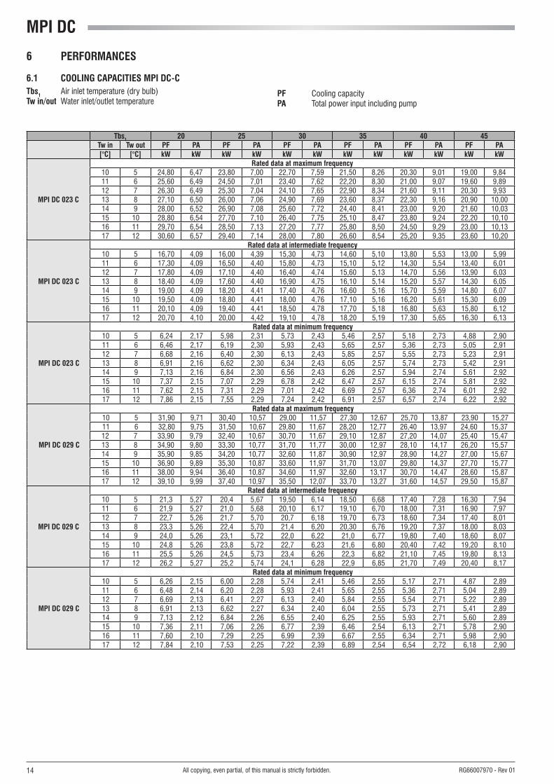
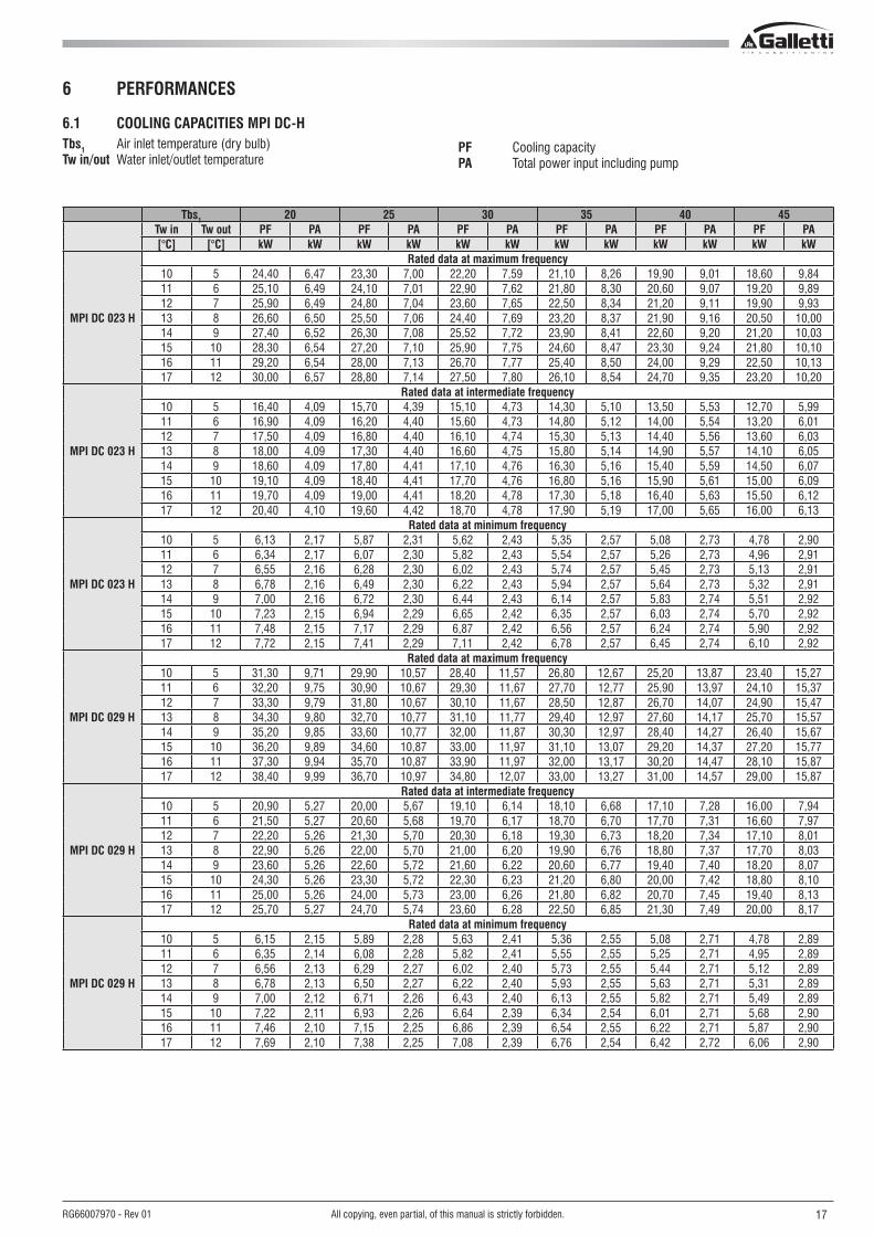
6 PeRFORManCeS
6.1 COOlInG CaPaCITIeS MPI DC-CTbs1 Air inlet temperature (dry bulb)Tw in/out Water inlet/outlet temperature
PF Cooling capacityPa Total power input including pump
Tbs1 20 25 30 35 40 45Tw in Tw out PF Pa PF Pa PF Pa PF Pa PF Pa PF Pa[°C] [°C] kW kW kW kW kW kW kW kW kW kW kW kW
MPI DC 08 C
Rated data at maximum frequency10 5 9,01 2,19 8,52 2,39 8,07 2,60 7,58 2,83 7,09 3,08 6,62 3,3511 6 9,31 2,19 8,82 2,40 8,33 2,61 7,84 2,85 7,34 3,11 6,84 3,3912 7 9,62 2,19 9,12 2,40 8,61 2,63 8,12 2,87 7,61 3,13 7,09 3,4113 8 9,92 2,19 9,44 2,41 8,91 2,64 8,39 2,89 7,86 3,16 7,34 3,4414 9 10,30 2,20 9,73 2,42 9,21 2,66 8,68 2,91 8,13 3,18 7,59 3,4715 10 10,61 2,19 10,06 2,42 9,52 2,67 8,96 2,93 8,42 3,20 7,86 3,4916 11 10,91 2,20 10,40 2,43 9,82 2,68 9,26 2,95 8,69 3,22 8,12 3,5217 12 11,22 2,19 10,71 2,43 10,14 2,69 9,57 2,96 8,98 3,25 8,38 3,54
MPI DC 08 C
Rated data at minimum frequency 10 5 5,93 1,43 5,61 1,55 5,30 1,68 4,99 1,81 4,68 1,96 4,38 2,1111 6 6,12 1,43 5,81 1,55 5,50 1,68 5,17 1,82 4,86 1,97 4,54 2,1312 7 6,32 1,42 6,01 1,55 5,68 1,68 5,36 1,82 5,03 1,98 4,70 2,1413 8 6,54 1,42 6,21 1,55 5,88 1,68 5,54 1,83 5,21 1,99 4,87 2,1514 9 6,75 1,41 6,42 1,55 6,08 1,69 5,73 1,84 5,39 2,00 5,04 2,1615 10 6,98 1,41 6,63 1,54 6,28 1,69 5,94 1,84 5,58 2,01 5,22 2,1816 11 7,20 1,40 6,84 1,54 6,49 1,69 6,13 1,85 5,76 2,01 5,41 2,1817 12 7,43 1,39 7,06 1,54 6,70 1,69 6,34 1,85 5,97 2,02 5,59 2,19
MPI DC 08 C
Rated data at intermediate frequency10 5 2,87 0,89 2,71 0,95 2,57 1,01 2,43 1,07 2,27 1,14 2,12 1,2111 6 2,96 0,89 2,82 0,95 2,66 1,01 2,51 1,07 2,36 1,14 2,20 1,2212 7 3,06 0,88 2,91 0,94 2,75 1,00 2,60 1,07 2,45 1,14 2,28 1,2213 8 3,16 0,88 3,01 0,94 2,86 1,00 2,69 1,07 2,53 1,14 2,37 1,2214 9 3,27 0,87 3,11 0,94 2,95 1,00 2,78 1,07 2,62 1,15 2,46 1,2315 10 3,38 0,87 3,21 0,93 3,05 1,00 2,89 1,07 2,71 1,15 2,55 1,2316 11 3,49 0,86 3,32 0,93 3,15 1,00 2,98 1,07 2,81 1,15 2,63 1,2317 12 3,60 0,85 3,43 0,92 3,25 0,99 3,08 1,07 2,91 1,15 2,72 1,23
MPI DC 010 C
Rated data at maximum frequency10 5 11,7 2,92 11,1 3,18 10,50 3,47 9,91 3,79 9,29 4,13 8,68 4,4911 6 12,1 2,91 11,5 3,18 10,90 3,48 10,30 3,80 9,61 4,15 8,99 4,5212 7 12,5 2,90 11,8 3,19 11,2 3,49 10,60 3,82 9,93 4,17 9,29 4,5513 8 12,8 2,90 12,2 3,18 11,6 3,50 10,90 3,83 10,30 4,19 9,61 4,5714 9 13,2 2,89 12,6 3,21 11,9 3,50 11,3 3,85 10,60 4,21 9,92 4,5915 10 13,6 2,87 13,0 3,18 12,3 3,50 11,6 3,86 10,90 4,23 10,30 4,6116 11 14,0 2,86 13,4 3,18 12,7 3,51 12,0 3,87 11,30 4,24 10,60 4,6417 12 14,5 2,85 13,8 3,17 13,1 3,52 12,4 3,88 11,60 4,26 10,90 4,66
MPI DC 010 C
Rated data at intermediate frequency10 5 7,37 1,82 6,99 1,97 6,62 2,13 6,52 2,30 5,87 2,48 5,49 2,6811 6 7,62 1,81 7,23 1,97 6,84 2,13 6,46 2,30 6,08 2,49 5,69 2,6912 7 7,84 1,80 7,46 1,96 7,07 2,13 6,69 2,30 6,29 2,49 5,90 2,6913 8 8,10 1,79 7,70 1,96 7,32 2,12 6,91 2,31 6,51 2,50 6,09 2,7014 9 8,35 1,78 7,96 1,95 7,56 2,12 7,14 2,31 6,72 2,50 6,30 2,7115 10 8,61 1,77 8,21 1,94 7,80 2,12 7,37 2,31 6,94 2,51 6,52 2,7216 11 8,88 1,75 8,47 1,93 8,04 2,11 7,61 2,31 7,18 2,51 6,74 2,7217 12 9,15 1,74 8,73 1,92 8,29 2,11 7,85 2,31 7,41 2,52 6,96 2,73
MPI DC 010 C
Rated data at minimum frequency 10 5 3,19 1,15 3,03 1,22 2,87 1,28 2,70 1,35 2,54 1,43 2,37 1,5111 6 3,30 1,14 3,13 1,21 2,97 1,28 2,80 1,35 2,63 1,43 2,46 1,5112 7 3,41 1,13 3,24 1,21 3,07 1,28 2,90 1,35 2,73 1,43 2,55 1,5113 8 3,52 1,13 3,35 1,20 3,18 1,27 3,00 1,35 2,82 1,43 2,65 1,5214 9 3,64 1,12 3,46 1,19 3,28 1,27 3,10 1,35 2,92 1,43 2,74 1,5215 10 3,76 1,11 3,57 1,19 3,39 1,26 3,21 1,34 3,03 1,43 2,84 1,5216 11 3,87 1,10 3,69 1,18 3,50 1,26 3,32 1,34 3,13 1,43 2,94 1,5217 12 3,99 1,09 3,81 1,17 3,62 1,25 3,43 1,34 3,23 1,43 3,04 1,52

13All copying, even partial, of this manual is strictly forbidden.RG66007970 - Rev 01
6 PeRFORManCeS
6.1 COOlInG CaPaCITIeS MPI DC-CTbs1 Air inlet temperature (dry bulb)Tw in/out Water inlet/outlet temperature
PF Cooling capacityPa Total power input including pump
Tbs1 20 25 30 35 40 45Tw in Tw out PF Pa PF Pa PF Pa PF Pa PF Pa PF Pa[°C] [°C] kW kW kW kW kW kW kW kW kW kW kW kW
MPI DC 014 C
Rated data at maximum frequency10 5 15,7 4,10 15,0 4,44 14,30 4,83 13,40 5,26 12,50 5,75 11,50 6,2611 6 16,2 4,11 15,5 4,46 14,70 4,85 13,90 5,29 12,90 5,77 11,90 6,3012 7 16,7 4,11 16,0 4,48 15,2 4,87 14,30 5,31 13,30 5,81 12,30 6,3313 8 17,3 4,12 16,5 4,48 15,7 4,90 14,70 5,34 13,80 5,84 12,70 6,3614 9 17,8 4,12 17,0 4,50 16,1 4,92 15,2 5,36 14,20 5,86 13,10 6,4115 10 18,4 4,13 17,6 4,52 16,6 4,93 15,6 5,39 14,60 5,90 13,50 6,4316 11 19,0 4,14 18,1 4,53 17,1 4,95 16,1 5,42 15,10 5,93 13,90 6,4717 12 19,5 4,14 18,6 4,54 17,6 4,97 16,6 5,45 15,50 5,95 14,40 6,51
MPI DC 014 C
Rated data at intermediate frequency10 5 10,60 2,59 10,10 2,80 9,60 3,01 9,09 3,26 8,50 3,53 7,89 3,8211 6 10,90 2,59 10,40 2,80 9,91 3,02 9,39 3,27 8,80 3,53 8,16 3,8312 7 11,30 2,59 10,80 2,80 10,20 3,02 9,68 3,27 9,09 3,55 8,43 3,8413 8 11,60 2,59 11,10 2,80 10,60 3,03 10,00 3,28 9,38 3,56 8,71 3,8614 9 12,00 2,58 11,50 2,80 10,90 3,03 10,30 3,29 9,70 3,57 9,00 3,8715 10 12,40 2,58 11,80 2,80 11,30 3,03 10,70 3,29 10,00 3,58 9,30 3,8816 11 12,80 2,58 12,20 2,80 11,60 3,04 11,00 3,30 10,30 3,59 9,60 3,9017 12 13,20 2,58 12,60 2,80 12,00 3,04 11,30 3,31 10,60 3,60 9,90 3,92
MPI DC 014 C
Rated data at minimum frequency 10 5 4,02 1,45 3,84 1,54 3,66 1,63 3,47 1,72 3,26 1,83 3,03 1,9411 6 4,16 1,45 3,97 1,54 3,79 1,63 3,59 1,72 3,38 1,83 3,14 1,9412 7 4,31 1,44 4,11 1,53 3,92 1,62 3,72 1,72 3,50 1,83 3,26 1,9513 8 4,47 1,44 4,26 1,53 4,06 1,62 3,85 1,72 3,62 1,83 3,37 1,9514 9 4,62 1,43 4,41 1,53 4,20 1,62 3,98 1,72 3,75 1,83 3,49 1,9515 10 4,79 1,43 4,56 1,52 4,35 1,62 4,12 1,72 3,88 1,83 3,61 1,9516 11 4,95 1,42 4,72 1,52 4,50 1,61 4,26 1,71 4,01 1,83 3,74 1,9517 12 5,12 1,42 4,88 1,52 4,65 1,61 4,41 1,71 4,14 1,83 3,86 1,95
MPI DC 018 C
Rated data at maximum frequency10 5 20,40 6,19 19,40 6,74 18,40 7,36 17,20 8,05 15,90 8,82 14,50 9,6411 6 21,00 6,21 20,00 6,77 18,90 7,40 17,70 8,10 16,40 8,87 15,00 9,7212 7 21,60 6,24 20,70 6,81 19,50 7,44 18,20 8,16 16,90 8,93 15,40 9,7613 8 22,30 6,26 21,30 6,84 20,10 7,49 18,80 8,21 17,40 8,99 15,90 9,8314 9 23,00 6,28 21,90 6,88 20,70 7,54 19,30 8,27 17,90 9,05 16,40 9,9115 10 23,70 6,31 22,50 6,91 21,30 7,58 19,90 8,32 18,50 9,12 16,90 9,9816 11 24,30 6,33 23,20 6,94 21,90 7,62 20,50 8,38 19,00 9,18 17,40 10,0417 12 25,10 6,35 23,90 6,97 22,40 7,68 21,00 8,44 19,60 9,24 19,70 10,10
MPI DC 018 C
Rated data at intermediate frequency10 5 13,30 3,36 12,70 3,61 12,10 3,91 11,40 4,24 10,70 4,61 9,88 5,0111 6 13,70 3,36 13,10 3,62 12,50 3,92 11,80 4,26 11,00 4,63 10,20 5,0312 7 14,20 3,35 13,60 3,62 12,90 3,93 12,20 4,27 11,40 4,65 10,50 5,0613 8 14,60 3,35 14,00 3,62 13,30 3,94 12,60 4,28 11,80 4,67 10,90 5,0814 9 15,10 3,34 14,50 3,63 13,70 3,94 13,00 4,30 12,10 4,69 11,20 5,1015 10 15,60 3,33 14,90 3,63 14,10 3,96 13,40 4,32 12,50 4,70 11,60 5,1316 11 16,10 3,32 15,40 3,63 14,60 3,96 13,,8 4,33 12,90 4,72 11,90 5,1517 12 16,60 3,31 15,80 3,62 15,00 3,97 14,20 4,34 13,20 4,74 12,30 5,18
MPI DC 018 C
Rated data at minimum frequency 10 5 3,98 1,45 3,80 1,53 3,63 1,62 3,44 1,72 3,24 1,82 3,01 1,9311 6 4,13 1,44 3,94 1,53 3,76 1,62 3,56 1,71 3,35 1,82 3,12 1,9312 7 4,28 1,43 4,09 1,53 3,88 1,62 3,69 1,71 3,47 1,82 3,23 1,9413 8 4,45 1,42 4,24 1,52 4,03 1,61 3,82 1,71 3,59 1,82 3,34 1,9414 9 4,61 1,41 4,39 1,51 4,17 1,61 3,95 1,71 3,71 1,82 3,46 1,9415 10 4,79 1,40 4,55 1,50 4,32 1,60 4,08 1,70 3,83 1,82 3,57 1,9416 11 4,96 1,39 4,72 1,49 4,48 1,59 4,22 1,70 3,96 1,82 3,69 1,9417 12 5,16 1,37 4,89 1,48 4,63 1,59 4,36 1,70 4,09 1,82 3,81 1,94
MPI DC
14 All copying, even partial, of this manual is strictly forbidden. RG66007970 - Rev 01
6 PeRFORManCeS
6.1 COOlInG CaPaCITIeS MPI DC-CTbs1 Air inlet temperature (dry bulb)Tw in/out Water inlet/outlet temperature
PF Cooling capacityPa Total power input including pump
Tbs1 20 25 30 35 40 45Tw in Tw out PF Pa PF Pa PF Pa PF Pa PF Pa PF Pa[°C] [°C] kW kW kW kW kW kW kW kW kW kW kW kW
MPI DC 023 C
Rated data at maximum frequency10 5 24,80 6,47 23,80 7,00 22,70 7,59 21,50 8,26 20,30 9,01 19,00 9,8411 6 25,60 6,49 24,50 7,01 23,40 7,62 22,20 8,30 21,00 9,07 19,60 9,8912 7 26,30 6,49 25,30 7,04 24,10 7,65 22,90 8,34 21,60 9,11 20,30 9,9313 8 27,10 6,50 26,00 7,06 24,90 7,69 23,60 8,37 22,30 9,16 20,90 10,0014 9 28,00 6,52 26,90 7,08 25,60 7,72 24,40 8,41 23,00 9,20 21,60 10,0315 10 28,80 6,54 27,70 7,10 26,40 7,75 25,10 8,47 23,80 9,24 22,20 10,1016 11 29,70 6,54 28,50 7,13 27,20 7,77 25,80 8,50 24,50 9,29 23,00 10,1317 12 30,60 6,57 29,40 7,14 28,00 7,80 26,60 8,54 25,20 9,35 23,60 10,20
MPI DC 023 C
Rated data at intermediate frequency10 5 16,70 4,09 16,00 4,39 15,30 4,73 14,60 5,10 13,80 5,53 13,00 5,9911 6 17,30 4,09 16,50 4,40 15,80 4,73 15,10 5,12 14,30 5,54 13,40 6,0112 7 17,80 4,09 17,10 4,40 16,40 4,74 15,60 5,13 14,70 5,56 13,90 6,0313 8 18,40 4,09 17,60 4,40 16,90 4,75 16,10 5,14 15,20 5,57 14,30 6,0514 9 19,00 4,09 18,20 4,41 17,40 4,76 16,60 5,16 15,70 5,59 14,80 6,0715 10 19,50 4,09 18,80 4,41 18,00 4,76 17,10 5,16 16,20 5,61 15,30 6,0916 11 20,10 4,09 19,40 4,41 18,50 4,78 17,70 5,18 16,80 5,63 15,80 6,1217 12 20,70 4,10 20,00 4,42 19,10 4,78 18,20 5,19 17,30 5,65 16,30 6,13
MPI DC 023 C
Rated data at minimum frequency 10 5 6,24 2,17 5,98 2,31 5,73 2,43 5,46 2,57 5,18 2,73 4,88 2,9011 6 6,46 2,17 6,19 2,30 5,93 2,43 5,65 2,57 5,36 2,73 5,05 2,9112 7 6,68 2,16 6,40 2,30 6,13 2,43 5,85 2,57 5,55 2,73 5,23 2,9113 8 6,91 2,16 6,62 2,30 6,34 2,43 6,05 2,57 5,74 2,73 5,42 2,9114 9 7,13 2,16 6,84 2,30 6,56 2,43 6,26 2,57 5,94 2,74 5,61 2,9215 10 7,37 2,15 7,07 2,29 6,78 2,42 6,47 2,57 6,15 2,74 5,81 2,9216 11 7,62 2,15 7,31 2,29 7,01 2,42 6,69 2,57 6,36 2,74 6,01 2,9217 12 7,86 2,15 7,55 2,29 7,24 2,42 6,91 2,57 6,57 2,74 6,22 2,92
MPI DC 029 C
Rated data at maximum frequency10 5 31,90 9,71 30,40 10,57 29,00 11,57 27,30 12,67 25,70 13,87 23,90 15,2711 6 32,80 9,75 31,50 10,67 29,80 11,67 28,20 12,77 26,40 13,97 24,60 15,3712 7 33,90 9,79 32,40 10,67 30,70 11,67 29,10 12,87 27,20 14,07 25,40 15,4713 8 34,90 9,80 33,30 10,77 31,70 11,77 30,00 12,97 28,10 14,17 26,20 15,5714 9 35,90 9,85 34,20 10,77 32,60 11,87 30,90 12,97 28,90 14,27 27,00 15,6715 10 36,90 9,89 35,30 10,87 33,60 11,97 31,70 13,07 29,80 14,37 27,70 15,7716 11 38,00 9,94 36,40 10,87 34,60 11,97 32,60 13,17 30,70 14,47 28,60 15,8717 12 39,10 9,99 37,40 10,97 35,50 12,07 33,70 13,27 31,60 14,57 29,50 15,87
MPI DC 029 C
Rated data at intermediate frequency10 5 21,3 5,27 20,4 5,67 19,50 6,14 18,50 6,68 17,40 7,28 16,30 7,9411 6 21,9 5,27 21,0 5,68 20,10 6,17 19,10 6,70 18,00 7,31 16,90 7,9712 7 22,7 5,26 21,7 5,70 20,7 6,18 19,70 6,73 18,60 7,34 17,40 8,0113 8 23,3 5,26 22,4 5,70 21,4 6,20 20,30 6,76 19,20 7,37 18,00 8,0314 9 24,0 5,26 23,1 5,72 22,0 6,22 21,0 6,77 19,80 7,40 18,60 8,0715 10 24,8 5,26 23,8 5,72 22,7 6,23 21,6 6,80 20,40 7,42 19,20 8,1016 11 25,5 5,26 24,5 5,73 23,4 6,26 22,3 6,82 21,10 7,45 19,80 8,1317 12 26,2 5,27 25,2 5,74 24,1 6,28 22,9 6,85 21,70 7,49 20,40 8,17
MPI DC 029 C
Rated data at minimum frequency 10 5 6,26 2,15 6,00 2,28 5,74 2,41 5,46 2,55 5,17 2,71 4,87 2,8911 6 6,48 2,14 6,20 2,28 5,93 2,41 5,65 2,55 5,36 2,71 5,04 2,8912 7 6,69 2,13 6,41 2,27 6,13 2,40 5,84 2,55 5,54 2,71 5,22 2,8913 8 6,91 2,13 6,62 2,27 6,34 2,40 6,04 2,55 5,73 2,71 5,41 2,8914 9 7,13 2,12 6,84 2,26 6,55 2,40 6,25 2,55 5,93 2,71 5,60 2,8915 10 7,36 2,11 7,06 2,26 6,77 2,39 6,46 2,54 6,13 2,71 5,78 2,9016 11 7,60 2,10 7,29 2,25 6,99 2,39 6,67 2,55 6,34 2,71 5,98 2,9017 12 7,84 2,10 7,53 2,25 7,22 2,39 6,89 2,54 6,54 2,72 6,18 2,90

15All copying, even partial, of this manual is strictly forbidden.RG66007970 - Rev 01
6 PeRFORManCeS
6.1 COOlInG CaPaCITIeS MPI DC-hTbs1 Air inlet temperature (dry bulb)Tw in/out Water inlet/outlet temperature
PF Cooling capacityPa Total power input including pump
Tbs1 20 25 30 35 40 45Tw in Tw out PF Pa PF Pa PF Pa PF Pa PF Pa PF Pa[°C] [°C] kW kW kW kW kW kW kW kW kW kW kW kW
MPI DC 08 h
Rated data at maximum frequency10 5 8,83 2,19 8,35 2,39 7,91 2,60 7,43 2,83 6,95 3,08 6,49 3,3511 6 9,13 2,19 8,65 2,40 8,17 2,61 7,69 2,85 7,20 3,11 6,71 3,3912 7 9,43 2,19 8,94 2,40 8,44 2,63 7,96 2,87 7,46 3,13 6,95 3,4113 8 9,73 2,19 9,25 2,41 8,74 2,64 8,23 2,89 7,71 3,16 7,20 3,4414 9 10,10 2,20 9,54 2,42 9,03 2,66 8,51 2,91 7,97 3,18 7,44 3,4715 10 10,40 2,19 9,86 2,42 9,33 2,67 8,78 2,93 8,25 3,20 7,71 3,4916 11 10,70 2,20 10,20 2,43 9,63 2,68 9,08 2,95 8,52 3,22 7,96 3,5217 12 11,00 2,19 10,50 2,43 9,94 2,69 9,38 2,96 8,80 3,25 8,22 3,54
MPI DC 08 h
Rated data at intermediate frequency10 5 5,81 1,43 5,50 1,55 5,20 1,68 4,89 1,81 4,59 1,96 4,29 2,1111 6 6,00 1,43 5,70 1,55 5,39 1,68 5,07 1,82 4,76 1,97 4,45 2,1312 7 6,20 1,42 5,89 1,55 5,57 1,68 5,25 1,82 4,93 1,98 4,61 2,1413 8 6,41 1,42 6,09 1,55 5,76 1,68 5,43 1,83 5,11 1,99 4,77 2,1514 9 6,62 1,41 6,29 1,55 5,96 1,69 5,62 1,84 5,28 2,00 4,94 2,1615 10 6,84 1,41 6,50 1,54 6,16 1,69 5,82 1,84 5,47 2,01 5,12 2,1816 11 7,06 1,40 6,71 1,54 6,36 1,69 6,01 1,85 5,65 2,01 5,30 2,1817 12 7,28 1,39 6,92 1,54 6,57 1,69 6,22 1,85 5,85 2,02 5,48 2,19
MPI DC 08 h
Rated data at minimum frequency10 5 2,81 0,89 2,66 0,95 2,52 1,01 2,38 1,07 2,23 1,14 2,08 1,2111 6 2,90 0,89 2,76 0,95 2,61 1,01 2,46 1,07 2,31 1,14 2,16 1,2212 7 3,00 0,88 2,85 0,94 2,70 1,00 2,55 1,07 2,40 1,14 2,24 1,2213 8 3,10 0,88 2,95 0,94 2,80 1,00 2,64 1,07 2,48 1,14 2,32 1,2214 9 3,21 0,87 3,05 0,94 2,89 1,00 2,73 1,07 2,57 1,15 2,41 1,2315 10 3,31 0,87 3,15 0,93 2,99 1,00 2,83 1,07 2,66 1,15 2,50 1,2316 11 3,42 0,86 3,25 0,93 3,09 1,00 2,92 1,07 2,75 1,15 2,58 1,2317 12 3,53 0,85 3,36 0,92 3,19 0,99 3,02 1,07 2,85 1,15 2,67 1,23
MPI DC 010 h
Rated data at maximum frequency10 5 11,50 2,92 10,90 3,18 10,30 3,47 9,72 3,79 9,12 4,13 8,52 4,4911 6 11,80 2,91 11,20 3,18 10,60 3,48 10,10 3,80 9,43 4,15 8,82 4,5212 7 12,20 2,90 11,60 3,19 11,00 3,49 10,40 3,82 9,74 4,17 9,11 4,5513 8 12,60 2,90 12,00 3,18 11,30 3,50 10,70 3,83 10,10 4,19 9,43 4,5714 9 13,00 2,89 12,40 3,21 11,70 3,50 11,10 3,85 10,40 4,21 9,74 4,5915 10 13,40 2,87 12,70 3,18 12,10 3,50 11,40 3,86 10,70 4,23 10,10 4,6116 11 13,80 2,86 13,10 3,18 12,40 3,51 11,80 3,87 11,10 4,24 10,40 4,6417 12 14,20 2,85 13,50 3,17 12,80 3,52 12,10 3,88 11,40 4,26 10,70 4,66
MPI DC 010 h
Rated data at intermediate frequency10 5 7,23 1,82 6,86 1,97 6,49 2,13 6,13 2,30 5,76 2,48 5,39 2,6811 6 7,47 1,81 7,09 1,97 6,72 2,13 6,34 2,30 5,96 2,49 5,58 2,6912 7 7,69 1,80 7,32 1,96 6,94 2,13 6,56 2,30 6,17 2,49 5,78 2,6913 8 7,94 1,79 7,56 1,96 7,18 2,12 6,78 2,31 6,39 2,50 5,98 2,7014 9 8,19 1,78 7,81 1,95 7,41 2,12 7,01 2,31 6,60 2,50 6,18 2,7115 10 8,45 1,77 8,05 1,94 7,65 2,12 7,23 2,31 6,81 2,51 6,39 2,7216 11 8,71 1,75 8,31 1,93 7,89 2,11 7,46 2,31 7,04 2,51 6,61 2,7217 12 8,98 1,74 8,56 1,92 8,13 2,11 7,71 2,31 7,27 2,52 6,83 2,73
MPI DC 010 h
Rated data at minimum frequency10 5 3,13 1,15 2,97 1,22 2,81 1,28 2,65 1,35 2,49 1,43 2,33 1,5111 6 3,24 1,14 3,07 1,21 2,91 1,28 2,75 1,35 2,58 1,43 2,42 1,5112 7 3,35 1,13 3,18 1,21 3,01 1,28 2,84 1,35 2,68 1,43 2,50 1,5113 8 3,46 1,13 3,29 1,20 3,12 1,27 2,95 1,35 2,77 1,43 2,60 1,5214 9 3,57 1,12 3,39 1,19 3,22 1,27 3,05 1,35 2,87 1,43 2,69 1,5215 10 3,68 1,11 3,50 1,19 3,33 1,26 3,15 1,34 2,97 1,43 2,78 1,5216 11 3,80 1,10 3,62 1,18 3,44 1,26 3,26 1,34 3,07 1,43 2,88 1,5217 12 3,92 1,09 3,74 1,17 3,55 1,25 3,36 1,34 3,17 1,43 2,98 1,52

MPI DC
16 All copying, even partial, of this manual is strictly forbidden. RG66007970 - Rev 01
6 PeRFORManCeS
6.1 COOlInG CaPaCITIeS MPI DC-hTbs1 Air inlet temperature (dry bulb)Tw in/out Water inlet/outlet temperature
PF Cooling capacityPa Total power input including pump
Tbs1 20 25 30 35 40 45Tw in Tw out PF Pa PF Pa PF Pa PF Pa PF Pa PF Pa[°C] [°C] kW kW kW kW kW kW kW kW kW kW kW kW
MPI DC 014 h
Rated data at maximum frequency10 5 15,40 4,10 14,70 4,44 14,00 4,83 13,20 5,26 12,30 5,75 11,30 6,2611 6 15,90 4,11 15,20 4,46 14,40 4,85 13,60 5,29 12,70 5,77 11,70 6,3012 7 16,40 4,11 15,70 4,48 14,90 4,87 14,00 5,31 13,10 5,81 12,00 6,3313 8 16,90 4,12 16,20 4,48 15,40 4,90 14,40 5,34 13,50 5,84 12,50 6,3614 9 17,50 4,12 16,70 4,50 15,80 4,92 14,90 5,36 13,90 5,86 12,80 6,4115 10 18,00 4,13 17,20 4,52 16,30 4,93 15,30 5,39 14,30 5,90 13,20 6,4316 11 18,60 4,14 17,70 4,53 16,80 4,95 15,80 5,42 14,80 5,93 13,70 6,4717 12 19,20 4,14 18,30 4,54 17,30 4,97 16,30 5,45 15,20 5,95 14,10 6,51
MPI DC 014 h
Rated data at intermediate frequency10 5 10,40 2,59 9,88 2,80 9,41 3,01 8,91 3,26 8,34 3,53 7,74 3,8211 6 10,70 2,59 10,20 2,80 9,72 3,02 9,21 3,27 8,63 3,53 8,00 3,8312 7 11,00 2,59 10,50 2,80 10,00 3,02 9,50 3,27 8,91 3,55 8,27 3,8413 8 11,40 2,59 10,90 2,80 10,40 3,03 9,81 3,28 9,20 3,56 8,54 3,8614 9 11,80 2,58 11,20 2,80 10,70 3,03 10,10 3,29 9,51 3,57 8,83 3,8715 10 12,10 2,58 11,60 2,80 11,10 3,03 10,40 3,29 9,80 3,58 9,12 3,8816 11 12,50 2,58 12,00 2,80 11,40 3,04 10,80 3,30 10,10 3,59 9,42 3,9017 12 12,90 2,58 12,40 2,80 11,80 3,04 11,10 3,31 10,40 3,60 9,71 3,92
MPI DC 014 h
Rated data at minimum frequency10 5 3,94 1,45 3,76 1,54 3,59 1,63 3,40 1,72 3,20 1,83 2,98 1,9411 6 4,08 1,45 3,90 1,54 3,72 1,63 3,52 1,72 3,31 1,83 3,08 1,9412 7 4,23 1,44 4,03 1,53 3,85 1,62 3,65 1,72 3,43 1,83 3,20 1,9513 8 4,38 1,44 4,18 1,53 3,98 1,62 3,78 1,72 3,55 1,83 3,31 1,9514 9 4,53 1,43 4,33 1,53 4,12 1,62 3,91 1,72 3,67 1,83 3,42 1,9515 10 4,69 1,43 4,47 1,52 4,27 1,62 4,04 1,72 3,80 1,83 3,54 1,9516 11 4,85 1,42 4,63 1,52 4,41 1,61 4,18 1,71 3,93 1,83 3,67 1,9517 12 5,03 1,42 4,79 1,52 4,56 1,61 4,32 1,71 4,06 1,83 3,79 1,95
MPI DC 018 h
Rated data at maximum frequency10 5 20,00 6,19 19,10 6,74 18,00 7,36 16,80 8,05 15,60 8,82 14,20 9,6411 6 20,60 6,21 19,60 6,77 18,60 7,40 17,40 8,10 16,10 8,87 14,70 9,7212 7 21,20 6,24 20,30 6,81 19,10 7,44 17,90 8,16 16,60 8,93 15,20 9,7613 8 21,90 6,26 20,90 6,84 19,70 7,49 18,40 8,21 17,10 8,99 15,60 9,8314 9 22,60 6,28 21,40 6,88 20,30 7,54 19,00 8,27 17,50 9,05 16,10 9,9115 10 23,20 6,31 22,00 6,91 20,90 7,58 19,50 8,32 18,10 9,12 16,60 9,9816 11 23,90 6,33 22,80 6,94 21,40 7,62 20,10 8,38 18,60 9,18 17,10 10,0417 12 24,60 6,35 23,40 6,97 22,00 7,68 20,60 8,44 19,20 9,24 17,60 10,10
MPI DC 018 h
Rated data at intermediate frequency10 5 13,00 3,36 12,50 3,61 11,90 3,91 11,20 4,24 10,50 4,61 9,69 5,0111 6 13,40 3,36 12,90 3,62 12,30 3,92 11,60 4,26 10,80 4,63 10,00 5,0312 7 13,90 3,35 13,30 3,62 12,70 3,93 11,90 4,27 11,20 4,65 10,30 5,0613 8 14,30 3,35 13,70 3,62 13,10 3,94 12,30 4,28 11,50 4,67 10,70 5,0814 9 14,80 3,34 14,20 3,63 13,50 3,94 12,70 4,30 11,90 4,69 11,00 5,1015 10 15,30 3,33 14,60 3,63 13,90 3,96 13,10 4,32 12,20 4,70 11,30 5,1316 11 15,80 3,32 15,10 3,63 14,30 3,96 13,50 4,33 12,60 4,72 11,70 5,1517 12 16,30 3,31 15,50 3,62 14,70 3,97 13,90 4,34 13,00 4,74 12,10 5,18
MPI DC 018 h
Rated data at minimum frequency10 5 3,91 1,45 3,73 1,53 3,56 1,62 3,37 1,72 3,18 1,82 2,96 1,9311 6 4,05 1,44 3,87 1,53 3,69 1,62 3,49 1,71 3,29 1,82 3,06 1,9312 7 4,20 1,43 4,01 1,53 3,80 1,62 3,62 1,71 3,40 1,82 3,17 1,9413 8 4,36 1,42 4,15 1,52 3,96 1,61 3,74 1,71 3,52 1,82 3,28 1,9414 9 4,52 1,41 4,31 1,51 4,09 1,61 3,87 1,71 3,64 1,82 3,39 1,9415 10 4,69 1,40 4,46 1,50 4,24 1,60 4,01 1,70 3,76 1,82 3,50 1,9416 11 4,87 1,39 4,63 1,49 4,39 1,59 4,14 1,70 3,88 1,82 3,62 1,9417 12 5,06 1,37 4,80 1,48 4,54 1,59 4,28 1,70 4,01 1,82 3,74 1,94
17All copying, even partial, of this manual is strictly forbidden.RG66007970 - Rev 01
6 PeRFORManCeS
6.1 COOlInG CaPaCITIeS MPI DC-hTbs1 Air inlet temperature (dry bulb)Tw in/out Water inlet/outlet temperature
PF Cooling capacityPa Total power input including pump
Tbs1 20 25 30 35 40 45Tw in Tw out PF Pa PF Pa PF Pa PF Pa PF Pa PF Pa[°C] [°C] kW kW kW kW kW kW kW kW kW kW kW kW
MPI DC 023 h
Rated data at maximum frequency10 5 24,40 6,47 23,30 7,00 22,20 7,59 21,10 8,26 19,90 9,01 18,60 9,8411 6 25,10 6,49 24,10 7,01 22,90 7,62 21,80 8,30 20,60 9,07 19,20 9,8912 7 25,90 6,49 24,80 7,04 23,60 7,65 22,50 8,34 21,20 9,11 19,90 9,9313 8 26,60 6,50 25,50 7,06 24,40 7,69 23,20 8,37 21,90 9,16 20,50 10,0014 9 27,40 6,52 26,30 7,08 25,52 7,72 23,90 8,41 22,60 9,20 21,20 10,0315 10 28,30 6,54 27,20 7,10 25,90 7,75 24,60 8,47 23,30 9,24 21,80 10,1016 11 29,20 6,54 28,00 7,13 26,70 7,77 25,40 8,50 24,00 9,29 22,50 10,1317 12 30,00 6,57 28,80 7,14 27,50 7,80 26,10 8,54 24,70 9,35 23,20 10,20
MPI DC 023 h
Rated data at intermediate frequency10 5 16,40 4,09 15,70 4,39 15,10 4,73 14,30 5,10 13,50 5,53 12,70 5,9911 6 16,90 4,09 16,20 4,40 15,60 4,73 14,80 5,12 14,00 5,54 13,20 6,0112 7 17,50 4,09 16,80 4,40 16,10 4,74 15,30 5,13 14,40 5,56 13,60 6,0313 8 18,00 4,09 17,30 4,40 16,60 4,75 15,80 5,14 14,90 5,57 14,10 6,0514 9 18,60 4,09 17,80 4,41 17,10 4,76 16,30 5,16 15,40 5,59 14,50 6,0715 10 19,10 4,09 18,40 4,41 17,70 4,76 16,80 5,16 15,90 5,61 15,00 6,0916 11 19,70 4,09 19,00 4,41 18,20 4,78 17,30 5,18 16,40 5,63 15,50 6,1217 12 20,40 4,10 19,60 4,42 18,70 4,78 17,90 5,19 17,00 5,65 16,00 6,13
MPI DC 023 h
Rated data at minimum frequency10 5 6,13 2,17 5,87 2,31 5,62 2,43 5,35 2,57 5,08 2,73 4,78 2,9011 6 6,34 2,17 6,07 2,30 5,82 2,43 5,54 2,57 5,26 2,73 4,96 2,9112 7 6,55 2,16 6,28 2,30 6,02 2,43 5,74 2,57 5,45 2,73 5,13 2,9113 8 6,78 2,16 6,49 2,30 6,22 2,43 5,94 2,57 5,64 2,73 5,32 2,9114 9 7,00 2,16 6,72 2,30 6,44 2,43 6,14 2,57 5,83 2,74 5,51 2,9215 10 7,23 2,15 6,94 2,29 6,65 2,42 6,35 2,57 6,03 2,74 5,70 2,9216 11 7,48 2,15 7,17 2,29 6,87 2,42 6,56 2,57 6,24 2,74 5,90 2,9217 12 7,72 2,15 7,41 2,29 7,11 2,42 6,78 2,57 6,45 2,74 6,10 2,92
MPI DC 029 h
Rated data at maximum frequency10 5 31,30 9,71 29,90 10,57 28,40 11,57 26,80 12,67 25,20 13,87 23,40 15,2711 6 32,20 9,75 30,90 10,67 29,30 11,67 27,70 12,77 25,90 13,97 24,10 15,3712 7 33,30 9,79 31,80 10,67 30,10 11,67 28,50 12,87 26,70 14,07 24,90 15,4713 8 34,30 9,80 32,70 10,77 31,10 11,77 29,40 12,97 27,60 14,17 25,70 15,5714 9 35,20 9,85 33,60 10,77 32,00 11,87 30,30 12,97 28,40 14,27 26,40 15,6715 10 36,20 9,89 34,60 10,87 33,00 11,97 31,10 13,07 29,20 14,37 27,20 15,7716 11 37,30 9,94 35,70 10,87 33,90 11,97 32,00 13,17 30,20 14,47 28,10 15,8717 12 38,40 9,99 36,70 10,97 34,80 12,07 33,00 13,27 31,00 14,57 29,00 15,87
MPI DC 029 h
Rated data at intermediate frequency10 5 20,90 5,27 20,00 5,67 19,10 6,14 18,10 6,68 17,10 7,28 16,00 7,9411 6 21,50 5,27 20,60 5,68 19,70 6,17 18,70 6,70 17,70 7,31 16,60 7,9712 7 22,20 5,26 21,30 5,70 20,30 6,18 19,30 6,73 18,20 7,34 17,10 8,0113 8 22,90 5,26 22,00 5,70 21,00 6,20 19,90 6,76 18,80 7,37 17,70 8,0314 9 23,60 5,26 22,60 5,72 21,60 6,22 20,60 6,77 19,40 7,40 18,20 8,0715 10 24,30 5,26 23,30 5,72 22,30 6,23 21,20 6,80 20,00 7,42 18,80 8,1016 11 25,00 5,26 24,00 5,73 23,00 6,26 21,80 6,82 20,70 7,45 19,40 8,1317 12 25,70 5,27 24,70 5,74 23,60 6,28 22,50 6,85 21,30 7,49 20,00 8,17
MPI DC 029 h
Rated data at minimum frequency10 5 6,15 2,15 5,89 2,28 5,63 2,41 5,36 2,55 5,08 2,71 4,78 2,8911 6 6,35 2,14 6,08 2,28 5,82 2,41 5,55 2,55 5,25 2,71 4,95 2,8912 7 6,56 2,13 6,29 2,27 6,02 2,40 5,73 2,55 5,44 2,71 5,12 2,8913 8 6,78 2,13 6,50 2,27 6,22 2,40 5,93 2,55 5,63 2,71 5,31 2,8914 9 7,00 2,12 6,71 2,26 6,43 2,40 6,13 2,55 5,82 2,71 5,49 2,8915 10 7,22 2,11 6,93 2,26 6,64 2,39 6,34 2,54 6,01 2,71 5,68 2,9016 11 7,46 2,10 7,15 2,25 6,86 2,39 6,54 2,55 6,22 2,71 5,87 2,9017 12 7,69 2,10 7,38 2,25 7,08 2,39 6,76 2,54 6,42 2,72 6,06 2,90
MPI DC
18 All copying, even partial, of this manual is strictly forbidden. RG66007970 - Rev 01
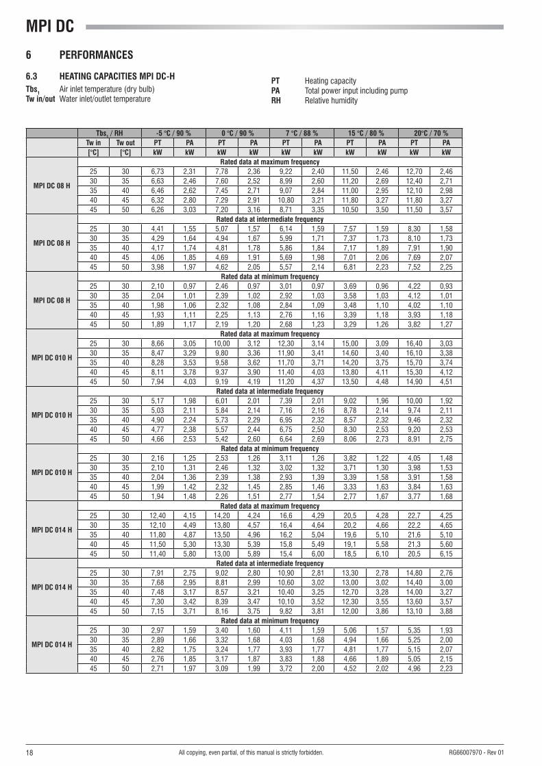
6 PeRFORManCeS
6.3 heaTInG CaPaCITIeS MPI DC-h Tbs1 Air inlet temperature (dry bulb)Tw in/out Water inlet/outlet temperature
PT Heating capacityPa Total power input including pumpRh Relative humidity
Tbs1 / Rh -5 °C / 90 % 0 °C / 90 % 7 °C / 88 % 15 °C / 80 % 20°C / 70 %Tw in Tw out PT Pa PT Pa PT Pa PT Pa PT Pa[°C] [°C] kW kW kW kW kW kW kW kW kW kW
MPI DC 08 h
Rated data at maximum frequency25 30 6,73 2,31 7,78 2,36 9,22 2,40 11,50 2,46 12,70 2,4630 35 6,63 2,46 7,60 2,52 8,99 2,60 11,20 2,69 12,40 2,7135 40 6,46 2,62 7,45 2,71 9,07 2,84 11,00 2,95 12,10 2,9840 45 6,32 2,80 7,29 2,91 10,80 3,21 11,80 3,27 11,80 3,2745 50 6,26 3,03 7,20 3,16 8,71 3,35 10,50 3,50 11,50 3,57
MPI DC 08 h
Rated data at intermediate frequency25 30 4,41 1,55 5,07 1,57 6,14 1,59 7,57 1,59 8,30 1,5830 35 4,29 1,64 4,94 1,67 5,99 1,71 7,37 1,73 8,10 1,7335 40 4,17 1,74 4,81 1,78 5,86 1,84 7,17 1,89 7,91 1,9040 45 4,06 1,85 4,69 1,91 5,69 1,98 7,01 2,06 7,69 2,0745 50 3,98 1,97 4,62 2,05 5,57 2,14 6,81 2,23 7,52 2,25
MPI DC 08 h
Rated data at minimum frequency25 30 2,10 0,97 2,46 0,97 3,01 0,97 3,69 0,96 4,22 0,9330 35 2,04 1,01 2,39 1,02 2,92 1,03 3,58 1,03 4,12 1,0135 40 1,98 1,06 2,32 1,08 2,84 1,09 3,48 1,10 4,02 1,1040 45 1,93 1,11 2,25 1,13 2,76 1,16 3,39 1,18 3,93 1,1845 50 1,89 1,17 2,19 1,20 2,68 1,23 3,29 1,26 3,82 1,27
MPI DC 010 h
Rated data at maximum frequency25 30 8,66 3,05 10,00 3,12 12,30 3,14 15,00 3,09 16,40 3,0330 35 8,47 3,29 9,80 3,36 11,90 3,41 14,60 3,40 16,10 3,3835 40 8,28 3,53 9,58 3,62 11,70 3,71 14,20 3,75 15,70 3,7440 45 8,11 3,78 9,37 3,90 11,40 4,03 13,80 4,11 15,30 4,1245 50 7,94 4,03 9,19 4,19 11,20 4,37 13,50 4,48 14,90 4,51
MPI DC 010 h
Rated data at intermediate frequency25 30 5,17 1,98 6,01 2,01 7,39 2,01 9,02 1,96 10,00 1,9230 35 5,03 2,11 5,84 2,14 7,16 2,16 8,78 2,14 9,74 2,1135 40 4,90 2,24 5,73 2,29 6,95 2,32 8,57 2,32 9,46 2,3240 45 4,77 2,38 5,57 2,44 6,75 2,50 8,30 2,53 9,20 2,5345 50 4,66 2,53 5,42 2,60 6,64 2,69 8,06 2,73 8,91 2,75
MPI DC 010 h
Rated data at minimum frequency25 30 2,16 1,25 2,53 1,26 3,11 1,26 3,82 1,22 4,05 1,4830 35 2,10 1,31 2,46 1,32 3,02 1,32 3,71 1,30 3,98 1,5335 40 2,04 1,36 2,39 1,38 2,93 1,39 3,39 1,58 3,91 1,5840 45 1,99 1,42 2,32 1,45 2,85 1,46 3,33 1,63 3,84 1,6345 50 1,94 1,48 2,26 1,51 2,77 1,54 2,77 1,67 3,77 1,68
MPI DC 014 h
Rated data at maximum frequency25 30 12,40 4,15 14,20 4,24 16,6 4,29 20,5 4,28 22,7 4,2530 35 12,10 4,49 13,80 4,57 16,4 4,64 20,2 4,66 22,2 4,6535 40 11,80 4,87 13,50 4,96 16,2 5,04 19,6 5,10 21,6 5,1040 45 11,50 5,30 13,30 5,39 15,8 5,49 19,1 5,58 21,3 5,6045 50 11,40 5,80 13,00 5,89 15,4 6,00 18,5 6,10 20,5 6,15
MPI DC 014 h
Rated data at intermediate frequency25 30 7,91 2,75 9,02 2,80 10,90 2,81 13,30 2,78 14,80 2,7630 35 7,68 2,95 8,81 2,99 10,60 3,02 13,00 3,02 14,40 3,0035 40 7,48 3,17 8,57 3,21 10,40 3,25 12,70 3,28 14,00 3,2740 45 7,30 3,42 8,39 3,47 10,10 3,52 12,30 3,55 13,60 3,5745 50 7,15 3,71 8,16 3,75 9,82 3,81 12,00 3,86 13,10 3,88
MPI DC 014 h
Rated data at minimum frequency25 30 2,97 1,59 3,40 1,60 4,11 1,59 5,06 1,57 5,35 1,9330 35 2,89 1,66 3,32 1,68 4,03 1,68 4,94 1,66 5,25 2,0035 40 2,82 1,75 3,24 1,77 3,93 1,77 4,81 1,77 5,15 2,0740 45 2,76 1,85 3,17 1,87 3,83 1,88 4,66 1,89 5,05 2,1545 50 2,71 1,97 3,09 1,99 3,72 2,00 4,52 2,02 4,96 2,23

19All copying, even partial, of this manual is strictly forbidden.RG66007970 - Rev 01
6 PeRFORManCeS
6.3 heaTInG CaPaCITIeS MPI DC-h Tbs1 Air inlet temperature (dry bulb)Tw in/out Water inlet/outlet temperature
PT Heating capacityPa Total power input including pumpRh Relative humidity
Tbs1 / Rh -5 °C / 90 % 0 °C / 90 % 7 °C / 88 % 15 °C / 80 % 20°C / 70 %Tw in Tw out PT Pa PT Pa PT Pa PT Pa PT Pa[°C] [°C] kW kW kW kW kW kW kW kW kW kW
MPI DC 018 h
Rated data at maximum frequency25 30 17,00 5,90 18,80 6,05 22,6 6,21 27,4 6,22 30,4 6,1530 35 16,60 6,43 18,50 6,56 22,3 6,71 25,9 8,35 29,7 6,7735 40 16,40 7,04 18,30 7,15 21,9 7,30 26,5 7,42 29,0 7,4440 45 16,10 7,71 18,00 7,83 21,4 7,98 25,9 8,35 28,3 8,1945 50 16,00 8,46 17,70 8,57 21,1 8,76 25,3 8,94 27,6 9,01
MPI DC 018 h
Rated data at intermediate frequency25 30 10,20 3,44 11,70 3,53 14,00 3,57 17,10 3,53 19,10 3,4630 35 9,93 3,71 11,40 3,78 13,70 3,84 16,70 3,84 18,60 3,8035 40 9,67 4,01 11,20 4,08 13,40 4,15 16,40 4,18 18,00 4,1840 45 9,54 4,36 11,00 4,43 13,20 4,50 16,00 4,56 17,50 4,5745 50 9,36 4,76 10,70 4,82 12,80 4,91 15,40 4,98 16,90 5,01
MPI DC 018 h
Rated data at minimum frequency25 30 2,95 1,58 3,37 1,60 4,07 1,60 5,03 1,55 5,26 1,9230 35 2,87 1,66 3,30 1,67 4,00 1,68 4,90 1,65 5,16 1,9935 40 2,80 1,75 3,22 1,76 3,91 1,77 4,76 1,76 5,07 2,0640 45 2,74 1,85 3,15 1,86 3,80 1,88 4,61 1,88 4,98 2,1445 50 2,69 1,96 3,08 1,98 3,70 1,99 4,47 2,01 4,89 2,22
MPI DC 023 h
Rated data at maximum frequency25 30 20,00 6,84 22,30 6,74 25,80 6,69 31,50 6,63 34,80 6,6030 35 19,40 7,11 21,90 7,15 25,40 7,18 31,10 7,18 34,30 7,1835 40 19,00 7,58 21,50 7,68 25,00 7,68 30,60 7,77 34,00 7,8440 45 18,60 8,17 21,10 8,31 25,10 8,44 30,20 8,55 33,20 8,5845 50 18,40 8,91 20,80 9,05 24,70 9,21 29,70 9,33 32,60 9,39
MPI DC 023 h
Rated data at intermediate frequency25 30 12,80 4,47 14,50 4,42 17,20 4,37 21,00 4,32 23,00 4,3030 35 12,50 4,66 14,10 4,66 16,70 4,66 20,50 4,66 22,50 4,6435 40 12,20 4,94 13,90 4,98 16,40 5,02 20,10 5,04 23,00 5,0440 45 12,00 5,29 13,50 5,35 16,20 5,41 19,60 5,47 21,70 5,4845 50 11,80 5,72 13,30 5,79 15,80 5,88 19,30 5,94 21,20 5,96
MPI DC 023 h
Rated data at minimum frequency25 30 4,74 2,43 5,34 2,40 6,38 2,37 7,78 2,34 9,11 2,3230 35 4,62 2,51 5,23 2,50 6,26 2,49 7,63 2,47 8,39 2,9635 40 4,51 2,61 5,12 2,62 6,13 2,63 7,49 2,62 8,27 3,0740 45 4,42 2,75 5,03 2,77 6,02 2,79 7,32 2,79 8,15 3,1845 50 4,35 2,92 4,95 2,95 5,91 2,97 7,16 2,98 8,02 3,29
MPI DC 029 h
Rated data at maximum frequency25 30 27,20 9,73 29,60 9,67 34,90 9,62 36,90 9,60 46,50 9,5130 35 26,40 10,22 29,80 10,32 34,40 10,36 40,70 12,87 45,90 10,4335 40 26,00 10,97 29,40 11,07 33,90 11,27 41,70 11,37 45,30 11,4740 45 25,60 11,87 29,00 12,07 33,40 12,27 40,70 12,87 44,40 12,5745 50 25,60 13,07 28,80 13,27 33,00 13,47 40,20 13,67 43,80 13,77
MPI DC 029 h
Rated data at intermediate frequency25 30 16,80 5,62 18,70 5,58 22,20 5,52 26,90 5,45 29,70 5,4130 35 16,30 5,89 18,30 5,92 21,80 5,93 26,50 5,91 29,10 5,9035 40 15,90 6,28 17,90 6,35 21,40 6,42 25,90 6,45 28,50 6,4540 45 15,50 6,77 17,60 6,86 21,00 6,96 25,30 7,03 27,80 7,0545 50 15,30 7,37 17,30 7,47 20,60 7,59 24,80 7,68 27,30 7,72
MPI DC 029 h
Rated data at minimum frequency25 30 4,72 2,40 5,33 2,38 6,39 2,34 7,75 2,30 9,02 2,2730 35 4,60 2,48 5,21 2,48 6,25 2,47 7,60 2,44 8,32 2,9435 40 4,49 2,59 5,11 2,60 6,12 2,61 7,46 2,60 8,19 3,0440 45 4,40 2,74 5,01 2,75 6,00 2,77 7,29 2,77 8,06 3,1545 50 4,33 2,91 4,93 2,93 5,89 2,95 7,12 2,96 7,93 3,26

MPI DC
20 All copying, even partial, of this manual is strictly forbidden. RG66007970 - Rev 01
7 SOUnD leVelS
leGenDlpa Total sound pressure level, weighted A, measured at a distance of 10 m, with a directivity factor of 2�lw Sound power level by octave band, not weightedlwa Total sound power level, weighted A
8 OPeRaTInG lIMITS
The graphs below illustrate the operating limits of MPI DC units (in the case of continuous operation) in relation to the outlet water temperature and outdoor air temperature�
Operating limitsChiller heat pump
min max min maxInletwatertemperature(°C) 8 20 1 25 42Outletwatertemperature(°C) 5 15 28 58 2
Watertemperaturedifferential(°C) 3 8 3 8Outdoorairtemperature(°C) -10 3 48 -10 35
1 Fortransitoryperiods(e.g.equipmentstartup)valuesupto25°Careallowed2 Valuethatmaybereachedonlyforoutdoorairtemperaturesexceeding0°C.3 Withcondensationcontrol:outdoorairTmin-15°C
Warning!: The units are designed to work with water and air temperatures falling within the range defined by the operating limits� Attempting to operate the units beyond these limits could cause irreparable damage to the units themselves�
8.1 OPeRaTInG lIMITS In ChIlleR MODe
Outlet water temperature (°C)
air t
empe
ratu
re (°
C)
6 PeRFORManCeS
6.4 InTeGRaTeD CaPaCITIeS
In the heat pump operation (heating mode), the actual heating capacities of units may be lower than the values shown in the table, due to defrosting cycles� To obtain the actual heating capacity, multiply the capacity values by the corrective coefficients given below�
Controlair temperature dry bulb (°C)
-5 0 5 >5
µchiller2 0,89 0,88 0,94 1
PCO XS 0,91 0,9 0,94 1
Modell
lw lw a lp a
125 hz 250 hz 500 hz 1000 hz 2000 hz 4000 hz 8000 hz Total low-noise version Total low-noise
versiondB dB dB dB dB dB dB dB (a) dB (a) dB (a) dB (a)
MPI DC 08 74,1 67,8 67,2 63,1 55,9 50,9 47,1 68,0 66,0 40,0 38,0
MPI DC 010 79,1 71,2 66,1 61,2 58,9 58,4 57,0 70,0 68,0 42,0 40,0
MPI DC 014 76,6 70,2 69,6 65,6 58,3 53,3 49,6 71,0 69,0 43,0 41,0
MPI DC 018 76,6 70,2 69,6 65,6 58,3 53,3 49,6 71,0 69,0 43,0 41,0
MPI DC 023 77,9 72,0 70,3 67,7 67,8 59,7 58,3 74,0 72,0 46,0 44,0
MPI DC 029 77,9 72,0 70,3 67,7 67,8 59,7 58,3 74,0 72,0 46,0 44,0

21
∆TW CPF/PT CPa CQw C∆pw1
3 0,975 1 1,63 2,64
4 0,99 1 1,24 1,53
5 1 1 1 1
6 1,015 1 0,85 0,72
7 1,03 1 0,74 0,54
8 1,04 1 0,65 0,42
All copying, even partial, of this manual is strictly forbidden.RG66007970 - Rev 01
8.2 OPeRaTInG lIMITS In heaTInG MODe
8.3 TheRMal CaRRIeR FlUID
The units belonging to the MPI DC series can work with mixtures of water and up to 30% ethylene glycol�
8 OPeRaTInG lIMITS
9 CalCUlaTIOn FaCTORS
9.1 Changeinoperatingparameterswith∆totherthan5°C
After identifying the unit's performance in the terms of the desired outlet water temperature, correct the value by multiplying it by the following corrective coefficients�
∆tW Difference between water inlet temperature and water outlet temperature
CPF/PT Corrective coefficient of cooling/heating capacity
CPa Correction coefficient of electrical input
CQw Correction coefficient of water flow rate
C∆pw1 Correction coefficient of pressure drop
9.2 WaTeR anD GlyCOl MIXTURe
Based on the minimum outlet water temperature, you can derive the percentage of ethylene glycol and the corrective coefficient using the table below�
PeRCenTaGe OF eThylene GlyCOl 0% 10% 20% 30% 40%
Minimum temp� of water produced 5°C 2°C -5°C -10°C -15°C
Mixturefreezingtemp.(°C) 0°C -4°C -14°C -18°C -24°C
Capacity correction factor 1,000 0,998 0,994 0,989 0,983
Water flow rate correction factor 1,000 1,047 1,094 1,140 1,199
Pressure drop correction factor 1,000 1,157 1,352 1,585 1,860
Warning The use of propylene glycol is not admitted with standard pumps� For further information, contact the manufacturer�
air temperature (°C)
Outle
t wat
er te
mpe
ratu
re (
°C)

MPI DC
22
PERDITE IN FREDDO
0
5
10
15
20
25
30
35
40
45
50
1200 1400 1600 1800 2000 2200 2400 2600 2800 3000 3200
PORTATA (l/h)
PERD
ITE
(kPa
)
MPIDC08
MPIDC010
MPIDC014
PERDITE IN FREDDO
20
25
30
35
40
45
50
55
60
65
70
2800 3200 3600 4000 4400 4800 5200 5600 6000 6400
PORTATA (l/h)
PERD
ITE
(kPa
)
MPIDC018
MPIDC023
MPIDC029
MPI DC 08 ÷ 014
MPI DC 018 ÷ 029
All copying, even partial, of this manual is strictly forbidden. RG66007970 - Rev 01
10 PReSSURe DROPS
10.1 PReSSURe DROPS, WaTeR SIDeThe diagram shows the evaporator pressure drops (∆p) as a function of the water flow rate (Qw),assuminganaveragewatertemperatureof10°C.
PReSSURe DROP - COOlInG
PReSSURe DROP - COOlInG
WaTeR FlOW RaTe (l/h)
WaTeR FlOW RaTe (l/h)
PReS
SURe
DRO
P (k
Pa)
PReS
SURe
DRO
P (k
Pa)

23
MPI DC 08
MPI DC 010-029
0
1
1
2
2
3
0 500 1000 1500 2000
∆p [kPa]
Qw [l/h]
MPE 004 - 008
0
5
10
15
20
25
0 2000 4000 6000 8000 10000 12000
∆p [kPa]
Qw [l/h]
MPI DC 010-029
MPI DC 08
All copying, even partial, of this manual is strictly forbidden.RG66007970 - Rev 01
10 PReSSURe DROPS
10.2 PReSSURe DROPS OF y FIlTeR
The diagram shows the evaporator pressure drops (∆p) as a function of the water flow rate (Qw),assuminganaveragewatertemperatureof10°C.

MPI DC
24
PREVALENZA UTILE IN FREDDO
70
80
90
100
110
120
130
140
150
160
1200 1400 1600 1800 2000 2200 2400 2600 2800 3000 3200
PORTATA (l/h)
PREV
ALE
NZA
(kPa
)
MPIDC08
MPIDC010
MPIDC014
MPI DC 08 ÷ 014
PREVALENZA UTILE IN FREDDO
40,0
50,0
60,0
70,0
80,0
90,0
100,0
110,0
120,0
130,0
140,0
150,0
2800 3200 3600 4000 4400 4800 5200 5600 6000 6400
PORTATA (l/h)
PREV
ALE
NZA
(kPa
)
MPIDC018
MPIDC023
MPIDC029
MPI DC 018 ÷ 029
All copying, even partial, of this manual is strictly forbidden. RG66007970 - Rev 01
11 aVaIlaBle heaD OF The UnIT
The diagram below shows the available head (Pu) of the unit as a function of the water flow rate (Qw),assuminganaveragewatertemperatureof10°C,netof pressure drops� Pressure drops of the Y filter are not counted�
aVaIlaBle heaD - COOlInG
aVaIlaBle heaD - COOlInG
WaTeR FlOW RaTe (l/h)
WaTeR FlOW RaTe (l/h)
aVaI
laBl
e he
aD (k
Pa)
aVaI
laBl
e he
aD (k
Pa)

25
���������
All copying, even partial, of this manual is strictly forbidden.RG66007970 - Rev 01
12 WaTeR CIRCUIT
When setting up the water circuit of the unit, it is advisable to follow the directions below and in any case comply with local or national regulations�Connect the pipes to the chiller using flexible couplings to prevent the transmission of vibrations and to compensate thermal expansions�
It is recommended to install the following components on the pipes:- temperature and pressure indicators for routine maintenance and monitoring of the unit� Checking the pressure on the water side will enable you to verify
whether the expansion tank is working efficiently and to promptly detect any water leaks within the equipment� - Traps on incoming and outgoing pipes for temperature measurements, which can provide a direct reading of the operating temperatures� - Regulating valves (gate valves) for isolating the unit from the water circuit�- Metal mesh filter (supplied), with a mesh size no greater than 1 mm, to be fitted on the inlet pipe to protect the exchanger from scale or impurities
present in the pipes.- Air vent valves, to be placed at the highest points of the water circuit for the purpose of bleeding air� The internal pipes of the unit are fitted with small
air vent valves for bleeding the unit itself� This operation may only be carried out when the unit is disconnected from the power supply�- Drainage valve and, where necessary, a drainage tank for emptying out the equipment for maintenance purposes or when the unit is taken out of serv-
ice at the end of the season� A 1” drainage valve is provided on the optional water buffer tank: this operation may only be carried out when the unit is disconnected from the power supply�
It is of fundamental importance that the incoming water supply is hooked up to the connection marked “Water Inlet”�otherwise the evaporator would be exposed to the risk of freezing since the antifreeze thermostat would not be able to perform its function; moreover the reverse cycle would not be respected in the cooling mode, resulting in additional risks of malfunctioning�
The dimensions and position of plumbing connections are shown in the dimension tables at the end of the manual�
The water circuit must be set up in such a way as to guarantee that the nominal flow rate of the water supplied to the evaporator remains constant (+/- 15%) in all operating conditions�A standard feature of MPI DC units is a device for controlling the flow rate (flow switch or differential pressure switch) in the water circuit in the immediate vicinity of the evaporator�
12.1 WaTeR COnTenT WIThIn The SySTeM anD ChaRGInG OF eXPanSIOn TanKIn models without buffer tank it is necessary to assure that the content of water within the system does not fall below 4�5 litres/kW in the case of heat pump models� This level is necessary to prevent the water temperature from falling below the indoor unit enabling threshold during defrost cycles�
n.B. kW in reference to rated capacityThe expansion tank is pre-charged to a pressure of 1�5 bars, sufficient for systems with a maximum height difference (H in the figure at the side) of 13 metres�For greater height differences, refer to the table below in order to adjust the charging pressure of the expansion tank accordingly�In no case should you exceed the maximum height difference Hmax = 35 m�
leGenDh Height difference of systempi Charging pressure of expansion tankCmax Maximum system water content
Models h (m)
pi (bar)
Cmax (l)
MPI
DC
08-0
29
<13 1,5 145
15 1,7 133
20 2,2 105
25 2,7 77
30 3,1 49

MPI DC
26 All copying, even partial, of this manual is strictly forbidden. RG66007970 - Rev 01
12 WaTeR CIRCUIT PlUMBInG DIaGRaMS)M
PI D
C (e
VaPO
RaTO
R an
D PU
MP)
MPI
DC
(eVa
PORa
TOR,
PUM
P an
D Ta
nK)
leGenD VS Safety valve eV Evaporator PD Differential pressure switch Ma Water pressure gauge VaS Air vent valve
Ve Expansion tank P Pump RS Drainage valve RC Water filling cock VU Check valve Sa Buffer tank

27All copying, even partial, of this manual is strictly forbidden.RG66007970 - Rev 01
13 eleCTRICal DaTa anD COnneCTIOnS
- The maximum electrical input is the mains electricity that must be available in order for the unit to work�- The maximum current absorption refers to the current that will trigger the internal safety devices of the unit� It is the maximum current allowed in the unit� This value may never be exceeded; it must be used as a reference for determining the size of the
power supply line and the related safety devices (refer to the wiring diagram supplied with the units)�
MPI DC 08 M 010 M 014 018 023 029 Maximum power input kW 4,1 5,6 7,1 10,7 10,8 21,9
Maximum current absorption A 16 26,6 20 22 28,5 43
Starting absorbed current A 10 10 10 10 10 10
Fan motor rated power kW 0,24 0,14 0,14 0,14 0,14 0,14
Fan motor rated current A 1,03 0,64 0,64 0,64 0,64 0,64
Pump motor rated power kW 0,14 0,48 0,65 0,65 0,65 0,65
Pump motor rated current A 0,58 2,7 3 3 3 3
Power supply V/f/Hz 230/1/50 400/3n/50
Auxiliary power supply V/f/Hz 230/1/50
Power cables mm2 4 4 6 6 10 10
PCD connecting cables mm2 AWG22 AWG22 AWG22 AWG22 AWG22 AWG22
PCDS connecting cables mm2 1 1 1 1 1 1
Safety fuse F A 20 20 25 25 32 32
Circuit breaker Il A 20 20 25 25 40 40

MPI DC
28
R
-IL
-IL-FL
L1
L1L2
T1T2
L1L2L3N
L2L3N
-FL
-IG
1 3 5 N
2 4 6 N
400
230
L N PE
L
N
PE
1 50
3+N 50
S T N P
PE
E
-IG
All copying, even partial, of this manual is strictly forbidden. RG66007970 - Rev 01
13 eleCTRICal DaTa anD COnneCTIOnS
DIaGRaM ShOWInG eleCTRICal COnneCTIOnS BeTWeen MPI DC anD PCDS ReMOTe COnTROl Panel
note: Should the unit go into an alarm status, a voltage of 24V will be present on the terminals of the electric control panel; where an interface with a voltage-free contact is desired, a relay must be fitted by the installer�
AlAR
M T
RIGG
ERED
SIG
nAll
InG
REM
oTE
SuM
MER
/WIn
TER
SElE
CTIo
n
on/o
FF S
WIT
CH
PCDS
PoW
ER S
uPPl
Y
ElECTRIC ConTRol BoARD TERMInAl BloCK
MaIn eleCTRIC COnneCTIOn OF SInGle-PhaSe anD ThRee-PhaSe UnITS
MPI DC WIRInG DIaGRaM WITh MyChIlleR ReMOTe COnTROl

29All copying, even partial, of this manual is strictly forbidden.RG66007970 - Rev 01
14 OVeRall DIMenSIOnS
MPI DC 08
legend:
1 Water inlet 1" female2 Water outlet 1" female3 Safety valve discharge outlet provided with rubber ring holder4 Water supply ½" male (optional tap)5 Water drainage ½" female6 Power supply Ø 28 mm7 Electric control board8 Fastening points for vibration dampers (accessory)

MPI DC
30 All copying, even partial, of this manual is strictly forbidden. RG66007970 - Rev 01
14 OVeRall DIMenSIOnS
MPI DC 10 - 18
legend:
1 Water inlet 1" ¼ female2 Water outlet 1" ¼ female3 Safety valve discharge outlet provided with rubber ring holder4 Water supply ½" male (optional tap)5 Water drainage ½" female6 Power supply Ø 28 mm7 Electric control board8 Fastening points for vibration dampers (accessory)

31
�
All copying, even partial, of this manual is strictly forbidden.RG66007970 - Rev 01
14 OVeRall DIMenSIOnS
MPI DC 23 - 29
legend:
1 Water inlet 1" ¼ female2 Water outlet 1" ¼ female3 Safety valve discharge outlet provided with rubber ring holder4 Water supply ½" male (optional tap)5 Water drainage ½" female6 Power supply Ø 28 mm7 Electric control board8 Fastening points for vibration dampers (accessory)
MPI DC
32 All copying, even partial, of this manual is strictly forbidden. RG66007970 - Rev 01
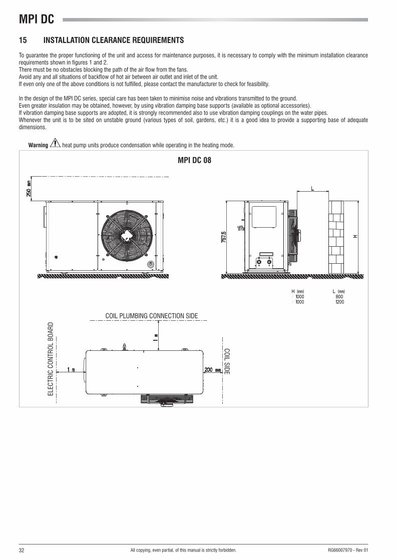
15 InSTallaTIOn CleaRanCe ReQUIReMenTS
To guarantee the proper functioning of the unit and access for maintenance purposes, it is necessary to comply with the minimum installation clearance requirements shown in figures 1 and 2� There must be no obstacles blocking the path of the air flow from the fans�Avoid any and all situations of backflow of hot air between air outlet and inlet of the unit�If even only one of the above conditions is not fulfilled, please contact the manufacturer to check for feasibility�
In the design of the MPI DC series, special care has been taken to minimise noise and vibrations transmitted to the ground� Even greater insulation may be obtained, however, by using vibration damping base supports (available as optional accessories)� If vibration damping base supports are adopted, it is strongly recommended also to use vibration damping couplings on the water pipes�Whenever the unit is to be sited on unstable ground (various types of soil, gardens, etc�) it is a good idea to provide a supporting base of adequate dimensions�
Warning heat pump units produce condensation while operating in the heating mode�
MPI DC 08
CoIl PluMBInG ConnECTIon SIDE
ElEC
TRIC
Con
TRol
BoA
RD
CoIl SIDE

33All copying, even partial, of this manual is strictly forbidden.RG66007970 - Rev 01
15 InSTallaTIOn CleaRanCe ReQUIReMenTS
MPI DC 10 - 18
MPI DC 23 - 29
CoIl PluMBInG ConnECTIon SIDE
ElEC
TRIC
Con
TRol
BoA
RD
CoIl SIDE
CoIl PluMBInG ConnECTIon SIDE
ElEC
TRIC
Con
TRol
BoA
RD
CoIl SIDE

MPI DC
34 All copying, even partial, of this manual is strictly forbidden. RG66007970 - Rev 01
16.1 POSITIOnInG OF VIBRaTIOn DaMPeRS (aCCeSSORy)
16 SITInG
MPI DC nO. OF VIBRaTIOn DaMPeRS 08 - 29 4
Vibration dampers
It is important to bear in mind the following aspects when choosing the best site for installing the unit:- Size and origin of water pipes;- location of the power supply;- Solidity of the supporting surface;- Avoid obstacles to the outflow of air from the fan which could cause back suction (see section on “installation clearance requirements”);- Direction of prevalent winds: (position the unit so that prevalent winds do not alter the fan air flow)� A prevalent wind blowing from a direction opposite to the fan air flow will reduce the maximum air temperature to a lower value than specified in the
operating limits, A wind blowing in the same direction as the fan air flow will increase the minimum air temperature to a higher value than specified in the operating limits� Also in the heat pump mode, wind may have the effect of reducing the unit's operating range�- Avoid the possible reverberation of sound waves; do not install the unit in narrow or cramped spaces;- Ensure adequate accessibility for maintenance or repairs (see section on “installation clearance requirements”)�
This device is not intended to be used by children or by people with physical, sensory or mental impairments, except under supervision. Make sure that children do not have access to the device.

35All copying, even partial, of this manual is strictly forbidden.RG66007970 - Rev 01
nOTeS

www.galletti.it
40010 Bentivoglio (Bo) Via Romagnoli 12/a Tel� + 39 051/8908111 - Fax� 051/8908122Company unI En ISo 9001 and oHSAS 18001 certified


![What is [Open] MPI?open]-mpi-1up.pdfMay 2008 Screencast: What is [Open] MPI? 3 MPI Forum • Published MPI-1 spec in 1994 • Published MPI-2 spec in 1996 Additions to MPI-1 • Recently](https://img.pdfslide.net/doc/110x75/6143c7b66b2ee0265c024306/what-is-open-mpi-open-mpi-1uppdf-may-2008-screencast-what-is-open-mpi-3.jpg)


![What is [Open] MPI?open]-mpi-2up.pdf2 May 2008 Screencast: What is [Open] MPI? 3 MPI Forum • Published MPI-1 spec in 1994 • Published MPI-2 spec in 1996 Additions to MPI-1 •](https://img.pdfslide.net/doc/110x75/6143c7b46b2ee0265c024305/what-is-open-mpi-open-mpi-2uppdf-2-may-2008-screencast-what-is-open-mpi.jpg)