Embed Size (px)
Citation preview
-
MPN(s): RT125, RT150, RT180
SKU(s): 191475, 191476, 191477
UPC(s): 719318384879, 719318384886, 719318384855
2
Safety information
Safety at all times
Thoroughly read and understand the instructions given in this manual before operation. Refer to the
“Safety Decal”, read all instructions noted on them.
⚫ Operator should be familiar with all functions of the unit.
⚫ Operate implement from the driver’s seat only.
⚫ Make sure all guards and shields are in place and secured before operating the implement.
⚫ Do not leave tractor or implement unattended with engine running.
⚫ Dismounting from a moving tractor could cause serious injury or death.
⚫ Do not stand between tractor and implement during hitching.
⚫ Keep hands, feet, and clothing away from power-driven parts.
⚫ Wear snug fitting clothing to avoid entanglement with moving parts.
⚫ Watch out for wires, trees, etc., when raising implement. Make sure all persons are clear of working area.
⚫ Turning tractor too tight may cause implement to ride up on wheels. This could result in injury or equipment damage.
Be aware of signal words
A signal word designates a degree or level of hazard seriousness. The signal words are:
! DANGER
Indicates an imminently hazardous situation which, if not avoids, will result in death or serious injury. This signal word is limited to the
most extreme situations, typically for machine components that, for functional purpose, cannot be guarded.
! WARNING
Indicates a potentially hazardous situation which, if not avoided, could result in death or serious injury, and includes hazards that are
exposed when guards are removed. It may also be used to alert against unsafe practices.
! CAUTION
Indicates a potentially hazardous situation which, if not avoided, may result in minor or moderate injury. It may also be used to alert
against unsafe practices.
For your protection
⚫ Thoroughly read and understand the “safety label” section, read all instructions noted on them.
Shutdown and storage
⚫ Lower machine to ground, put tractor in park, turn off engine, and remove the ignition key.
⚫ Detach and store implements in an area where children normally do not play. Secure implement by using blocks and supports.
Use safety lights and devices
⚫ Slow moving tractors, self-propelled equipment, and towed implements can create a hazard when driven on public roads. They are
difficult to see, especially at night.
⚫ Flashing warning lights and turn signals are recommended whenever driving on public roads.
Transport machinery safely
3
⚫ Comply with state and local laws.
⚫ Maximum transport speed for implement is 20 mph. Do not exceed. Never travel at a speed which does not allow adequate control
of steering and stopping. Some rough terrain requires a slower speed.
⚫ Sudden braking can cause a towed load to swerve and upset. Reduce speed if towed load is not equipped with brakes.
⚫ Do not tow a load that is more than double the weight of tractor.
Keep riders off machinery
⚫ Riders obstruct of operator’s view, they could be struck by foreign objects or thrown from the machine.
⚫ Never allow children to operate equipment.
Practice safe maintenance
⚫ Understand procedure before doing work. Use proper tools and equipment.
⚫ Work in a clean dry area.
⚫ Lower the implement to the ground, put tractor in park, turn off engine, and remove key before performing maintenance.
⚫ Allow implement to cool completely.
⚫ Do not grease or oil implement while it is operation.
⚫ Inspect all parts. Make sure parts are in good condition and installed properly.
⚫ Remove buildup of grease, oil or debris.
⚫ Remove all tools and unused parts from implement before operation.
Prepare for emergencies
⚫ Be prepared if a fire starts.
⚫ Keep a fist aid kit and fire extinguisher handy.
⚫ Keep emergency numbers for doctor, ambulance, hospital and fire department near phone.
Wear protective equipment
⚫ Protective clothing and equipment should be worn.
⚫ Wear clothing and equipment appropriate for the job. Avoid loose fitting clothing.
⚫ Prolonged exposure to loud noise can cause hearing impairment or hearing loss. Wear suitable hearing protection such as earmuffs
or earplugs.
⚫ Operating equipment safely requires the full attention of the operator. Avoid wearing radio headphones while operating machinery.
Avoid high pressure fluids hazard
⚫ Escaping fluid under pressure can penetrate the skin causing serious injury.
⚫ Avoid the hazard by relieving pressure before disconnecting hydraulic lines.
⚫ Use a piece of paper or cardboard, not body parts, to check for suspected leaks. Wear protective gloves and safety glasses or
goggles when working with hydraulic systems.
⚫ If an accident occurs, see a doctor immediately. Any fluid injected into the skin must be treated within a few hours or gangrene may
result.
Structure and their adjustment
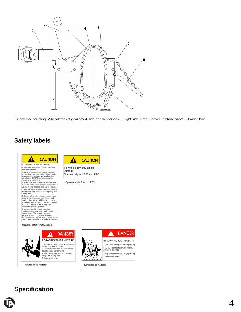
These series rotary tillers are tillage equipment by means of the compound motion both rotation of the blade and the tractor going
forward. Each rotary consists of transmission sets and working parts. Transmission sets include driveline, gearbox, side chain box
(gearbox). Working parts include blade and blade shaft. Headstock, the cover and trailing bar are assistant sets (Fig.1).
4
1-universal coupling 2-headstock 3-gearbox 4-side chain(gear)box 5.right side plate 6-cover 7-blade shaft 8-trailing bar
Safety labels
To Avoid Injury or Machine Damage:
1. Read and understand Operator's Manual
BEFORE operating.
2. Lower implement to the ground, place all
controls in neutral, stop engine, set park brake,
remove ignition key, and wait for all moving
parts to stop BEFORE servicing, repairing,
adjusting, or unplugging.
3. Stand clear when implement is in operation.
4. DO NOT allow riders or operate implement in
vicinity of other persons, animals, or buildings.
5. Keep all safety guards and devices in place.
Keep hands, feet, hair, and clothing away from
moving pars.
6. Escaping hydrualic fluid can cause serious
injury, keep all hydrualic lines, fittings, and
couplers tight and free of leaks before using.
7. Ballast tractor per tractor operator's manual.
8. DO NOT allow children or unqualified
persons to operate equipment.
9. Implements with smooth input shaft
gearboxes must have snap ring in place to
ensure proper PTO shaft connection.
10. Review safety instructions annually.11. Transporting requires secured safety locks,
safety chain, proper lighting, and lower speeds.
To Avoid Injury or Machine
Damage:
Operate only with 540 rpm PTO
ROTATING TINES HAZARD
1. DO NOT go under frame when tines are
turning or engine is running.
2. Disconnect and lockout power source
before adjusting or servicing.
3. Keep hands, feet, hair, and clothing
away from moving parts.
4. Keep others away.
THROWN OBJECT HAZARD
1. Keep deflector in place while operating.
2. DO NOT point outlet toward people,
animals, or buildings.
3. Stay away from outlet during operating.
4. Keep others away.
General safety instructions
Operate only 540rpm PTO
Rotating tines hazard Flying debris hazard
Specification
5
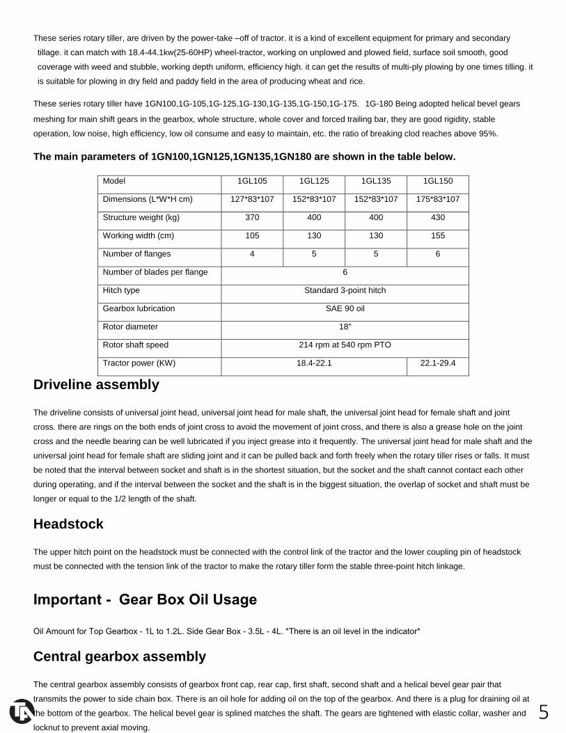
These series rotary tiller, are driven by the power-take –off of tractor. it is a kind of excellent equipment for primary and secondary
tillage. it can match with 18.4-44.1kw(25-60HP) wheel-tractor, working on unplowed and plowed field, surface soil smooth, good
coverage with weed and stubble, working depth uniform, efficiency high. it can get the results of multi-ply plowing by one times tilling. it
is suitable for plowing in dry field and paddy field in the area of producing wheat and rice.
These series rotary tiller have 1GN100,1G-105,1G-125,1G-130,1G-135,1G-150,1G-175,1G-180 Being adopted helical bevel gears
meshing for main shift gears in the gearbox, whole structure, whole cover and forced trailing bar, they are good rigidity, stable
operation, low noise, high efficiency, low oil consume and easy to maintain, etc. the ratio of breaking clod reaches above 95%.
The main parameters of 1GN100,1GN125,1GN135,1GN180 are shown in the table below.
Model 1GL105 1GL125 1GL135 1GL150
Dimensions (L*W*H cm) 127*83*107 152*83*107 152*83*107 175*83*107
Structure weight (kg) 370 400 400 430
Working width (cm) 105 130 130 155
Number of flanges 4 5 5 6
Number of blades per flange 6
Hitch type Standard 3-point hitch
Gearbox lubrication SAE 90 oil
Rotor diameter 18"
Rotor shaft speed 214 rpm at 540 rpm PTO
Tractor power (KW) 18.4-22.1 22.1-29.4
Driveline assembly
The driveline consists of universal joint head, universal joint head for male shaft, the universal joint head for female shaft and joint
cross. there are rings on the both ends of joint cross to avoid the movement of joint cross, and there is also a grease hole on the joint
cross and the needle bearing can be well lubricated if you inject grease into it frequently. The universal joint head for male shaft and the
universal joint head for female shaft are sliding joint and it can be pulled back and forth freely when the rotary tiller rises or falls. It must
be noted that the interval between socket and shaft is in the shortest situation, but the socket and the shaft cannot contact each other
during operating, and if the interval between the socket and the shaft is in the biggest situation, the overlap of socket and shaft must be
longer or equal to the 1/2 length of the shaft.
Headstock
The upper hitch point on the headstock must be connected with the control link of the tractor and the lower coupling pin of headstock
must be connected with the tension link of the tractor to make the rotary tiller form the stable three-point hitch linkage.
Important - Gear Box Oil Usage
Oil Amount for Top Gearbox - 1L to 1.2L. Side Gear Box - 3.5L - 4L. *There is an oil level in the indicator*
Central gearbox assembly
The central gearbox assembly consists of gearbox front cap, rear cap, first shaft, second shaft and a helical bevel gear pair that
transmits the power to side chain box. There is an oil hole for adding oil on the top of the gearbox. And there is a plug for draining oil at
the bottom of the gearbox. The helical bevel gear is splined matches the shaft. The gears are tightened with elastic collar, washer and
locknut to prevent axial moving.
6
In using, the bearing clearance and the gear backlash will be changed because of wearing of bearings and gears, so you must adjust
them (if necessary).
Adjustment of helical bevel gear backlash:
A proper backlash is the one of the condition for working normally. If the backlash is too large, it will result in the strong collision and
loud noise.
Precaution:
Helical bevel gear backlash must be adjusted after the clearance of bearing on the first shaft has been adjusted. For retaining the
clearance of bearing in which have been adjusted, for pinion, the total thickness of adjusted shims of the front and the hind bearing seat
on the first shaft must keep up. For example, when moving the pinion forward, the decrease –the adjusted shims of the hind –bearing
seat on the first shaft must be added to the front bearing seat on the first shaft, vice versa. For large helical bevel gear, when moving it
rightward, you must decrease the shims of the bearing seat of the large bevel gear.
In general, just move the pinion forward when you do it.
Adjustment of the bearing axial clearance on the second shaft
When the axial displacement was occurred very distinctly on the second shaft, you must adjust it in time as following steps: first, loosen
washer and screw down the lock nut, then adjusts the displacement of the bearing on the second shaft until there was no distinct axial
movement and easy to rotate the shaft.
Finally, lock the jam nut with the washer. This prevents the bearing from loosening.
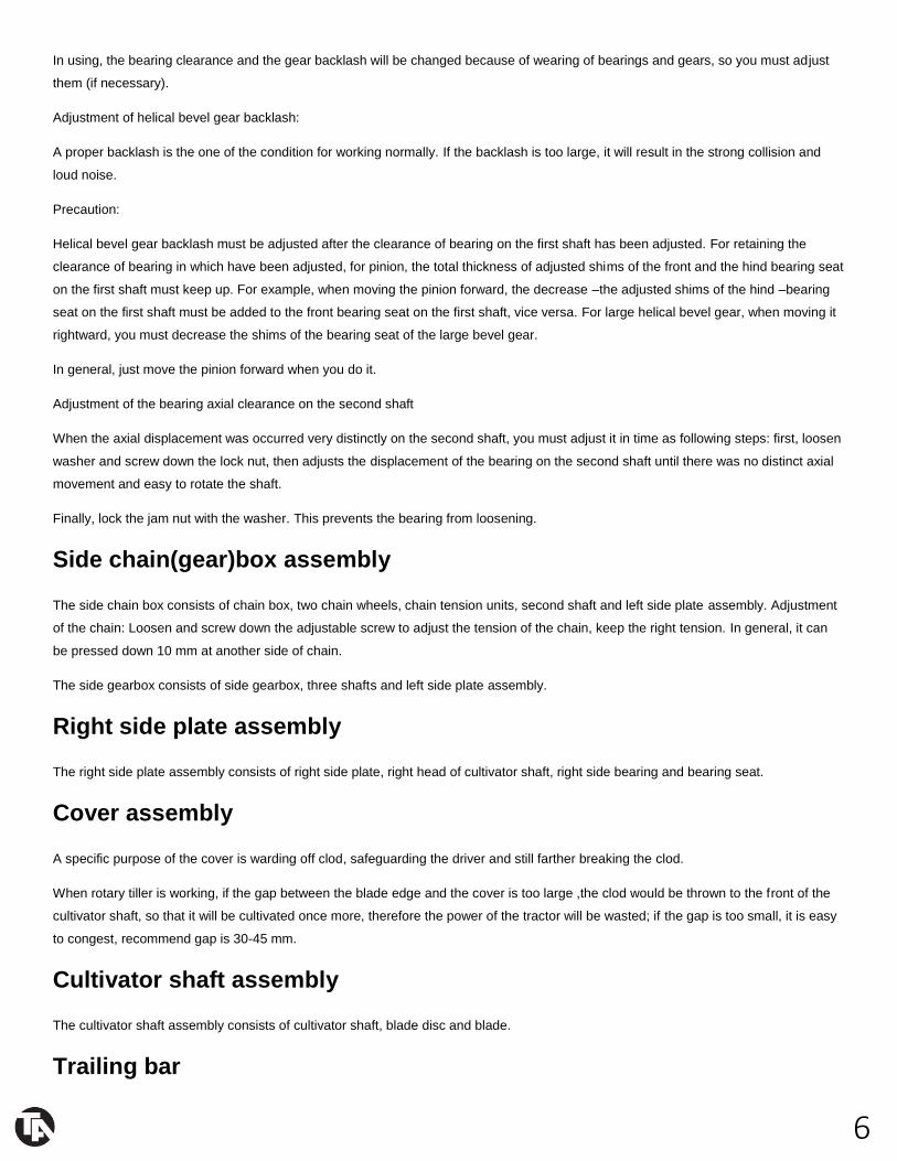
Side chain(gear)box assembly
The side chain box consists of chain box, two chain wheels, chain tension units, second shaft and left side plate assembly. Adjustment
of the chain: Loosen and screw down the adjustable screw to adjust the tension of the chain, keep the right tension. In general, it can
be pressed down 10 mm at another side of chain.
The side gearbox consists of side gearbox, three shafts and left side plate assembly.
Right side plate assembly
The right side plate assembly consists of right side plate, right head of cultivator shaft, right side bearing and bearing seat.
Cover assembly
A specific purpose of the cover is warding off clod, safeguarding the driver and still farther breaking the clod.
When rotary tiller is working, if the gap between the blade edge and the cover is too large ,the clod would be thrown to the front of the
cultivator shaft, so that it will be cultivated once more, therefore the power of the tractor will be wasted; if the gap is too small, it is easy
to congest, recommend gap is 30-45 mm.
Cultivator shaft assembly
The cultivator shaft assembly consists of cultivator shaft, blade disc and blade.
Trailing bar
7
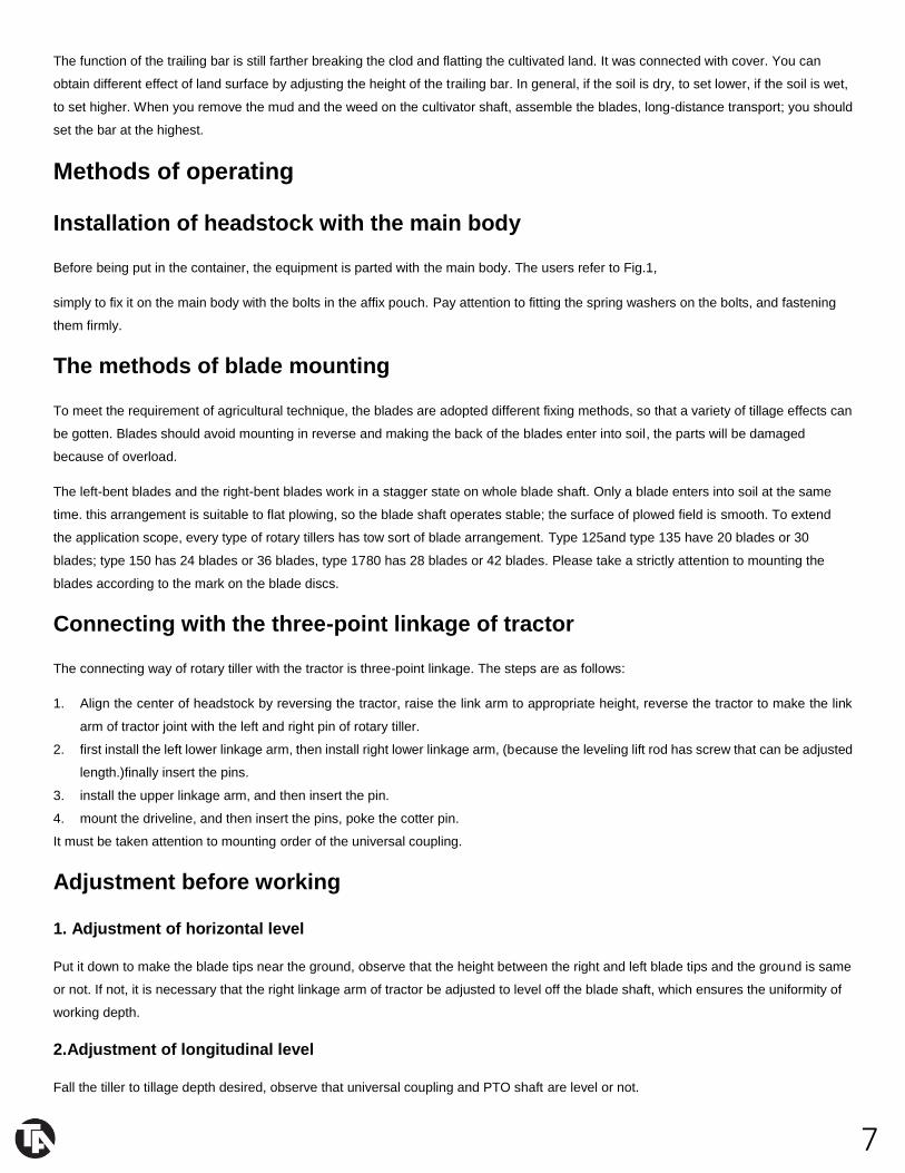
The function of the trailing bar is still farther breaking the clod and flatting the cultivated land. It was connected with cover. You can
obtain different effect of land surface by adjusting the height of the trailing bar. In general, if the soil is dry, to set lower, if the soil is wet,
to set higher. When you remove the mud and the weed on the cultivator shaft, assemble the blades, long-distance transport; you should
set the bar at the highest.
Methods of operating
Installation of headstock with the main body
Before being put in the container, the equipment is parted with the main body. The users refer to Fig.1,
simply to fix it on the main body with the bolts in the affix pouch. Pay attention to fitting the spring washers on the bolts, and fastening
them firmly.
The methods of blade mounting
To meet the requirement of agricultural technique, the blades are adopted different fixing methods, so that a variety of tillage effects can
be gotten. Blades should avoid mounting in reverse and making the back of the blades enter into soil, the parts will be damaged
because of overload.
The left-bent blades and the right-bent blades work in a stagger state on whole blade shaft. Only a blade enters into soil at the same
time. this arrangement is suitable to flat plowing, so the blade shaft operates stable; the surface of plowed field is smooth. To extend
the application scope, every type of rotary tillers has tow sort of blade arrangement. Type 125and type 135 have 20 blades or 30
blades; type 150 has 24 blades or 36 blades, type 1780 has 28 blades or 42 blades. Please take a strictly attention to mounting the
blades according to the mark on the blade discs.
Connecting with the three-point linkage of tractor
The connecting way of rotary tiller with the tractor is three-point linkage. The steps are as follows:
1. Align the center of headstock by reversing the tractor, raise the link arm to appropriate height, reverse the tractor to make the link
arm of tractor joint with the left and right pin of rotary tiller.
2. first install the left lower linkage arm, then install right lower linkage arm, (because the leveling lift rod has screw that can be adjusted
length.)finally insert the pins.
3. install the upper linkage arm, and then insert the pin.
4. mount the driveline, and then insert the pins, poke the cotter pin.
It must be taken attention to mounting order of the universal coupling.
Adjustment before working
1. Adjustment of horizontal level
Put it down to make the blade tips near the ground, observe that the height between the right and left blade tips and the ground is same
or not. If not, it is necessary that the right linkage arm of tractor be adjusted to level off the blade shaft, which ensures the uniformity of
working depth.
2.Adjustment of longitudinal level
Fall the tiller to tillage depth desired, observe that universal coupling and PTO shaft are level or not.
8
If the angle of universal coupling is too large, adjust the control link to make it nearly level, which can maintain that universal coupling
and the tiller work in the good condition.
Cultivating route
When working in a piece of larger land, in land plowing is adopted to reduce the empty time in turn land, to raise work efficiency. The
width of the plot selected is whole number multiple of the working width or near as possible, so as to decrease repeat tilling. The width
of the plot is commonly 15m or so, if too wide, the empty time in turn land will be longer, the efficiency be less, the repeat times of idle
motion be more, the mud depth be longer. The flat tillage in the medium and small fields refer to the in land plowing.
Starting of the tiller
First,filling with gear oil in the gearbox and the side chain box, injecting grease to the crosshead and the bearing seat of the blade shaft.
Then check for the looseness of all connecting bolts and nuts, if loosing, fastening it at once. If the crack and deforming are found in the
blades,they must be replaced.
Starting tractor: rise the tiller and the blade tip must be away from ground 150mm-200mm, and joint universal coupling, then run in 1-2
minutes, gear the operating gear position and increase the fuel throttle , control the leveling handle to make the tiller enter into the soil
gradually until the normal tillage depth at the same time.
Selecting of forward speed
The selecting principle of tiller forward speed: the tractor cannot overload constantly; the performance of breaking soil meet the needs
of agriculture requirement, furrow bottom and the soil surface are smooth. Not only be tillage quality ensured, but also the rated power
of tractor be made good use of, and the purpose of rising work efficiency must be attained.
Generally, rotary tilling directly:2km/h-5km/h,harrowing:5km/h-7km/h;if the unit draft of the soil is bigger, can select lower gear;
contrarily select higher gear; when working in dry fields, select lower gear; when working in paddy fields, select higher gear.
Operating of headstock
1) Using position control when the tiller works. The handle of draft control must be put in the position marked”up”.
2) When the handle of position control moves forward, the tiller fall down; contrarily the tiller rise.
3) After the tiller reaching to required depth, using the position hand-wheel to block it, in favor of that the tiller falls the same depth every
time.
4) The details refer to the instruction of matching tractor.
DRIVELINE DIMENSION
A PTO driveline is supplied with the machine. To ac-company the variety of 3 point hitch geometry available today, the driveline can be
too long for most machines or too short for others. It is very important that the drive- line be free to telescope but not to bottom out
when going through its working range. If the driveline bottoms out, the bearings on both the machine and tractor PTO shaft will be
overloaded and fail in a short time.
1. To determine the proper length of the driveline, follow this procedure:
9
a. Clear the area of bystanders, especially small children.
b. Attach the chipper to the tractor (see section), but do not attach the driveline.
c. Raise the machine until the input shaft is level with the tractor PTO shaft.
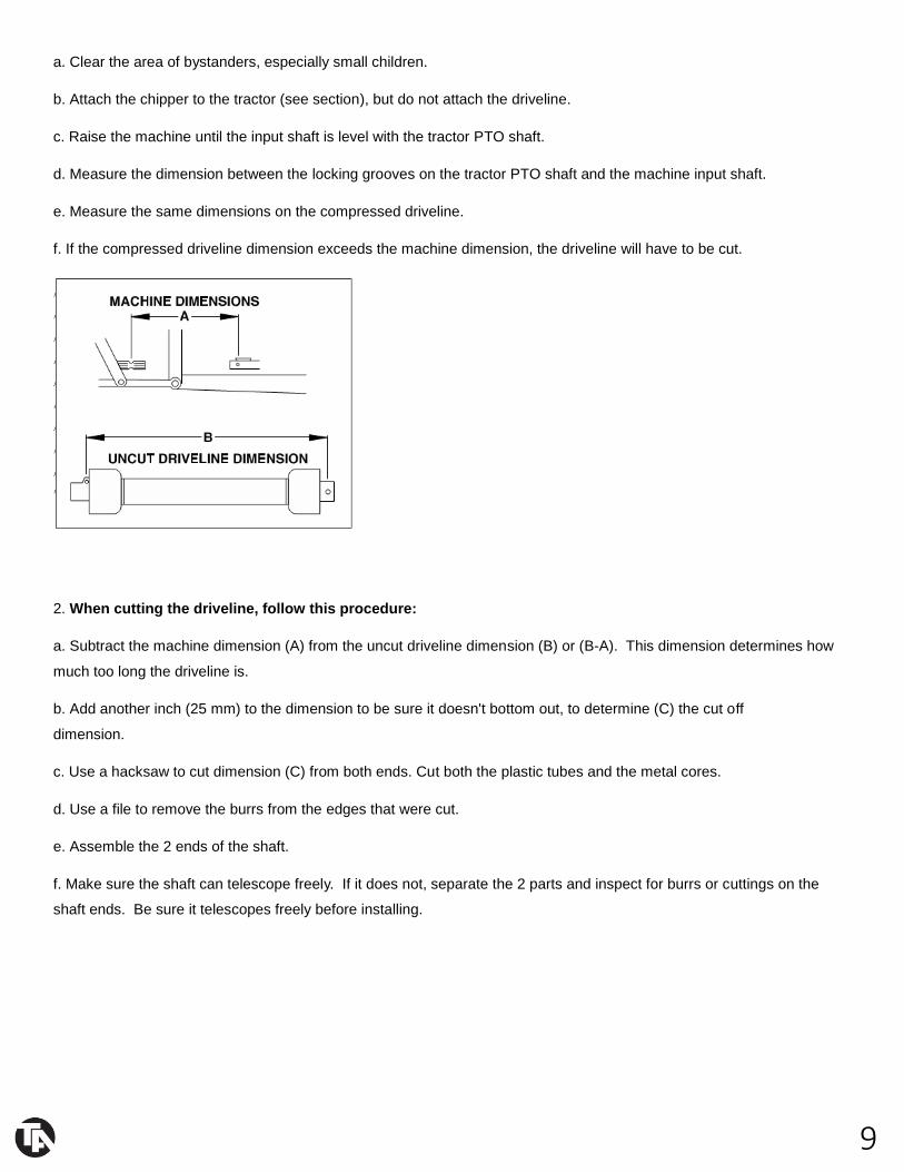
d. Measure the dimension between the locking grooves on the tractor PTO shaft and the machine input shaft.
e. Measure the same dimensions on the compressed driveline.
f. If the compressed driveline dimension exceeds the machine dimension, the driveline will have to be cut.
2. When cutting the driveline, follow this procedure:
a. Subtract the machine dimension (A) from the uncut driveline dimension (B) or (B-A). This dimension determines how
much too long the driveline is.
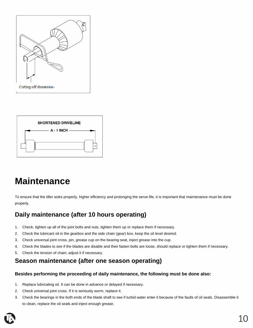
b. Add another inch (25 mm) to the dimension to be sure it doesn't bottom out, to determine (C) the cut off
dimension.
c. Use a hacksaw to cut dimension (C) from both ends. Cut both the plastic tubes and the metal cores.
d. Use a file to remove the burrs from the edges that were cut.
e. Assemble the 2 ends of the shaft.
f. Make sure the shaft can telescope freely. If it does not, separate the 2 parts and inspect for burrs or cuttings on the
shaft ends. Be sure it telescopes freely before installing.
10
Maintenance
To ensure that the tiller woks properly, higher efficiency and prolonging the serve life, it is important that maintenance must be done
properly.
Daily maintenance (after 10 hours operating)
1. Check, tighten up all of the joint bolts and nuts, tighten them up or replace them if necessary.
2. Check the lubricant oil in the gearbox and the side chain (gear) box, keep the oil level desired.
3. Check universal joint cross, pin, grease cup on the bearing seat, inject grease into the cup.
4. Check the blades to see if the blades are disable and their fasten bolts are loose, should replace or tighten them if necessary.
5. Check the tension of chain; adjust it if necessary.
Season maintenance (after one season operating)
Besides performing the proceeding of daily maintenance, the following must be done also:
1. Replace lubricating oil. It can be done in advance or delayed if necessary.
2. Check universal joint cross. If it is seriously worm, replace it.
3. Check the bearings in the both ends of the blade shaft to see if turbid water enter it because of the faults of oil seals. Disassemble it
to clean, replace the oil seals and inject enough grease.
11
4. Check all bearings; adjust or replace them if necessary.
5. Check helical bevel gears; adjust them if necessary.
Yearly maintenance (after one year operating)
1. Remove all dust and filth away from the tiller.
2. Drain out gear oil and disassemble the tiller to check on. If bearings be worn seriously or go wrong, it must be replaced; the parts
must be cleaned before assembled. Final, add new oil to standard oil level.
3. Disassemble and clean the bearings and their seat of blade shaft, replace the oil seals and inject enough grease.
4. Disassemble and clean the universal joint cross assembly, and clean the roller pins of the universal joint, replace them if necessary.
5. Check the fastener and the cotter pins, etc. If the part is rusty or worn seriously, or the disable, it must be replaced.
6. Check the blades to see if there is crack, wear and tear on them, or loss. It must be replaced or added if necessary.
7. Check the blade holder, replace or repair them if necessary.
8. Repair the cover and the trailing bar.
9. The rotary tiller must be placed indoor as possible during it parks, and be raised to make the blade tips leave the ground. The blades
and processing surface revealed must smeared oil to prevent from rusty. The surface in which the paint broken off must be painted
with the primitive colors to prevent from rusty.
Lubrication sites
Lubrication sites Purpose
Oil check screw plug Check the oil level of the gearbox and the side chain (gear)
box (injection should continue until oil overflows out from the
oil check hole).
Ventilate screw plug Ventilation of the side chain (gear)box
Grease cup of the joint cross Inject the grease into the joint cross (so that lubricate the
roller needle
Of the joint cross)
Grease cup of the bearing
seal on the cultivator shaft
Inject the grease into the bearing and the oil seals of the
cultivator Shaft(lubricate the bearings and the oil seals)

12
Troubleshooting
Problem Cause Solution
Universal coupling inclined too
much
Rotary tiller failed horizontal
Level
Adjust the horizontal level of The
tiller
One side sway chain of tractor is
too short
Adjust the chain
Universal coupling injured Direction mistaken Re-assemble correctly
Grease deficient Rinse neeble and inject grease
Sufficiently
Angle of universal coupling is
Too big or is gripped
Limit the rising position and re-
lock the position
Rotary tiller fallen down the
soil sharply
Fall the tiller down the soil
smoothly
Noise in gearbox The clearance between the two
Helical bevel gears is too large
Adjust this clearance
Bearing injured Replace bearing
Tooth of gear broken Replace gear
Noise in side chain box (type
1GL)
Foreign matter dropper in
chain box
Take foreign matter out of the
Chain box
The tension of chain is too lax Adjust the tension of chain
Chain and chain wheel excessive
wear
Replace chain and chain wheel
Bearing on the third shaft injured Replace bearing
Noise in side chain box (type
1G)
Foreign matter dropped in chain
box
Take foreign matter out of the
chain box
Bearing on the third shaft injured Replace bearing
Bearing on the middle shaft
injured
Replace bearing
Trouble rotation of cultivator
shaft
Gear or bearing injured or
gripped
Replace gear or bearing
There was no clearance between
the two helical bevel gears
Adjust the clearance of the helical
bevel
gear pair
Out of shape of left side plane Correct side plane
Cultivator shaft crooked or out
of shape
Correct or replace cultivator shaft
Cultivator shaft crooked or out of
shape
Clear away grass or soil

13
Blade slot injured Cultivator shaft twined with grass
or hold soil seriously
Clear away the stone from the
field
Blade run foul of stone so that it
suffers too much force
Assemble the blades correctly
Blade assembled on opposite
direction so that it suffers too
much force
Fall the tiller down the soil
smoothly
Blades crooked or broken Rotary tiller fallen down the soil
sharply so that it suffers too
much force
Replace the blades and clear
away
The stones from the field
Blades run foul of stone Rise the tiller and do not plough
when the tractor turns a corner in
the field
Doing plough when tractor turns
a corner in the field
Fall the tiller down smoothly
14
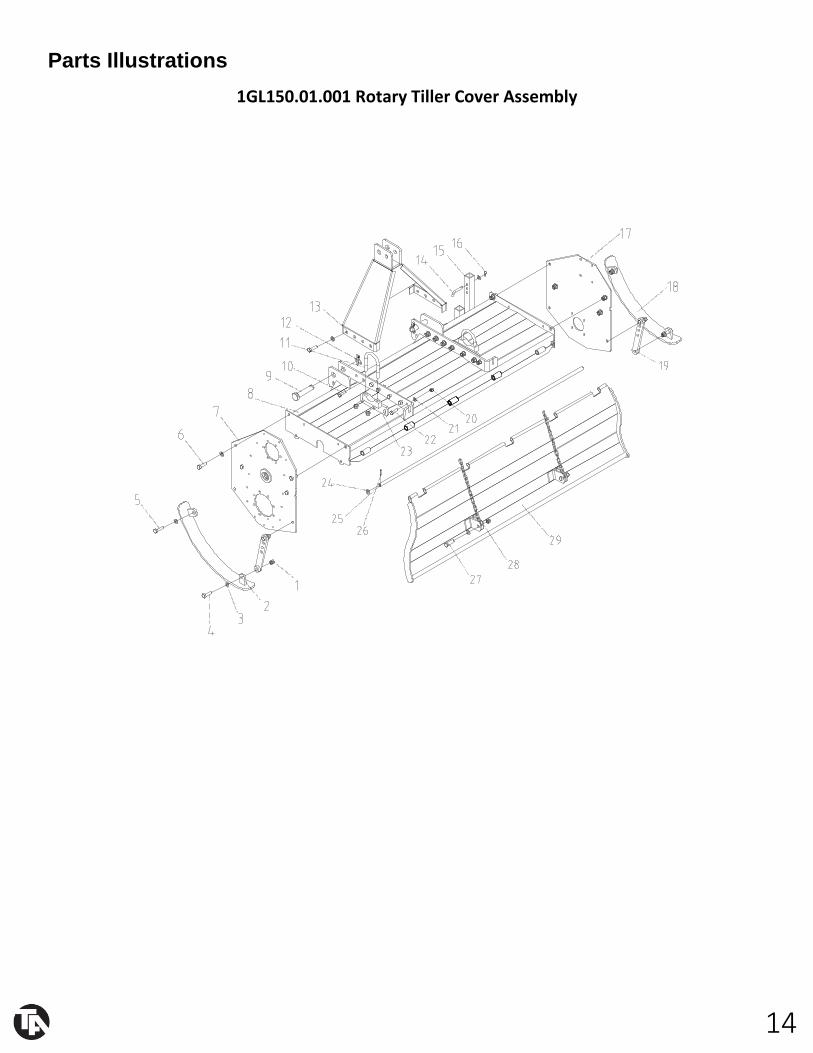
Parts Illustrations
1GL150.01.001 Rotary Tiller Cover Assembly

15
1GL150.01.001 Rotary Tiller Transmission Assembly Parts List
REF PART NUMBER DESCRIPTION QTY
1 GB/T889.1-2000 Nut M14 32
2 1GL155.01.014 Left limiting depth weldment 1
3 GB/T97.1-2002 Plain washer 14 32
4 GB/T5782-2002 Bolt M14*60 2
5 GB/T5782-2000 Bolt M14*40 8
6 GB/T5782-2000 Bolt M14*35 16
7 1GN230.01.014 Left lateral plate weldment 1
8 1GL155.01.010 Cover weldment 1
9 1GN230.01.107 Suspennsion pinΦ28 2
10 GB/T5782-2000 Bolt M14*45 2
11 1GN230.01.102 U-shaped hoop 2
12 FEL300.111 Locking pin 2
13 1GL155.01.013 Hanging weldment 1
14 1G135.00.107 Curving pin 1
15 1GN230.01.019 Supporting frame 1
16 FEL300.114 PinΦ28 2
17 1GL155.01.101 Right lateral plate weldment 1
18 1GL155.01.012 Right Limiting depth weldment 1
19 1GL155.01.016 Limiting depth linkage plate 2
20 GB/T889.1-2000 Nut M12 2
21 GB/T97.1-2002 Plain washer 12 3
22 GB/T5782-2000 Bolt M12*40 2
23 1GL155.01.015 U-shaped weldment 2
24 GB/T97.1-2002 Plain washer 16 2
25 1GL155.01.102 Long pin rod 1
26 GB/T91-2000 Pin2.5x45 2
27 GB/T5782-2000 Bolt M14*50 2
28 1GN230.01.017 Link 2
29 1GL155.01.011 Dam-board Weldment 1
16
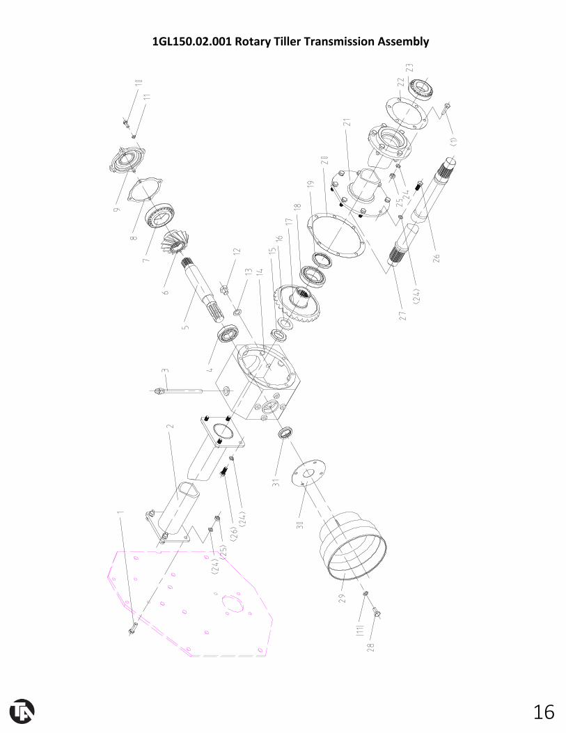
1GL150.02.001 Rotary Tiller Transmission Assembly
17

18
1GL150.02.001 Rotary Tiller Transmission Assembly Parts List
32 GB/T889.1-2000 Nut M8 15
REF PART NUMBER DESCRIPTION QTY
1 GB/T5783-2000 Bolt M10*35 10
2 1GL155.02.011 Outer spacer 1
3 1GN230.02.012 Breather plug 1
4 GB/T297-1994 Bearing 30207 1
5 1GN230.02.102 Drive shaft 1
6 1GN230.02.103 Drive gear wheel 1
7 GB/T297-1994 Bearing 32211 1
8 1GN230.02.105 Gasket 1
9 1GN230.02.104 Bearing support cover pinion 1
10 GB/T5783-2000 Bolt M8*20 4
11 GB/T93-1987 Spring washer 8 22
12 1GN230.02.117 Bolt 3
13 JB/T1002-1977 Gasket 16 4
14 1GN230.02.101 Gearbox housing 1
15 GB/T812-1988 Self locking nut M35*1.5 3
16 GB/T858-1988 Lock washer 3
17 1GN230.02.107 Driven gear wheel 1
18 GB/T297-1994 Bearing 32011 1
19 GB/T13871-1992 Oil seal FB55*72*8 1
20 1GN230.02.106 Gasket support 1
21 1GL155.02.012 Spacer 1
22 1GN230.02.109 Gasket 1
23 GB/T297-1994 Bearing 32209 1
24 GB/T93-1987 Spring washer 10 22
25 GB/T889.1-2000 Nut M10 10
26 GB/T5783-2000 Bolt M10*25 12
27 1GL155.02.101 Driven shaft 1
28 GB/T5783-2000 Bolt M8*16 4
29 1G135.02.117 Guard shade 1
30 1GN230.02.118 Protection support 1
31 GB/T13871-1992 Oil seal FB40*55*8 1

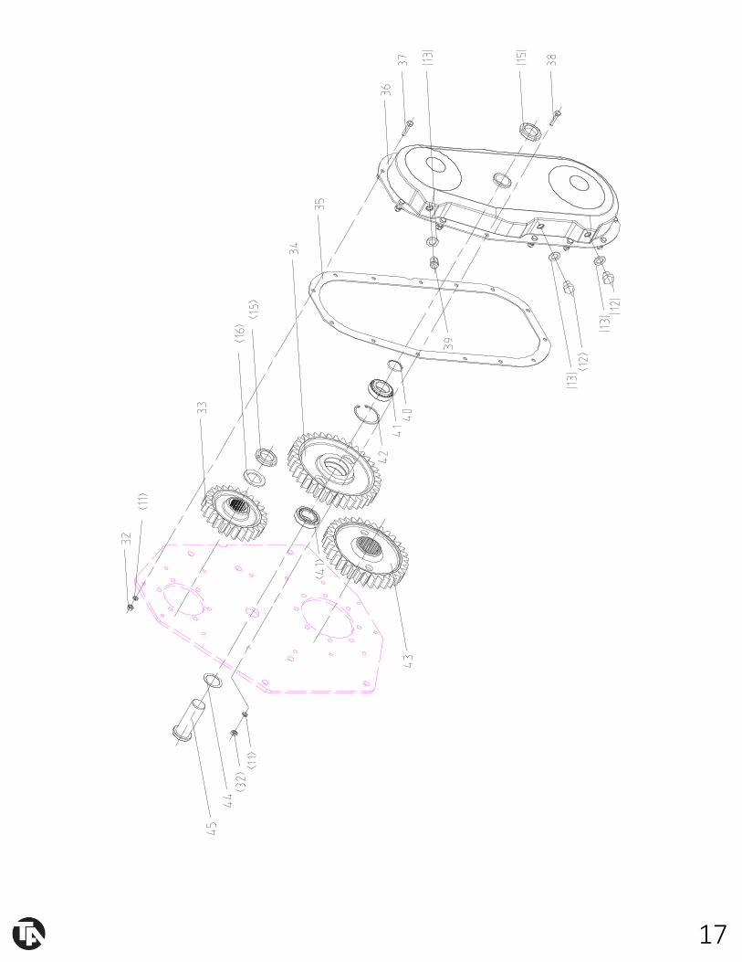
19
33 1GN230.02.111 Upper gear 1
34 1GN230.02.115 Central gear 1
35 1GN230.02.110 Drive cover gasket 1
36 1GN230.02.014 Gears cover 1
37 GB/T5783-2000 Bolt M8*25 12
38 GB/T5783-2000 Bolt M8*35 2
39 Oil breather plug 1
40 GB/T3452.1-1992 O-ring 34.5*2.65 1
41 GB/T297-1994 Bearing 32007 2
42 GB/T893.1-1986 Circlip 62 1
43 1GN230.02.116 Lower gear 1
44 1GN230.02.113 Gasket 1
45 1GN230.02.114 Gear hub 1
20
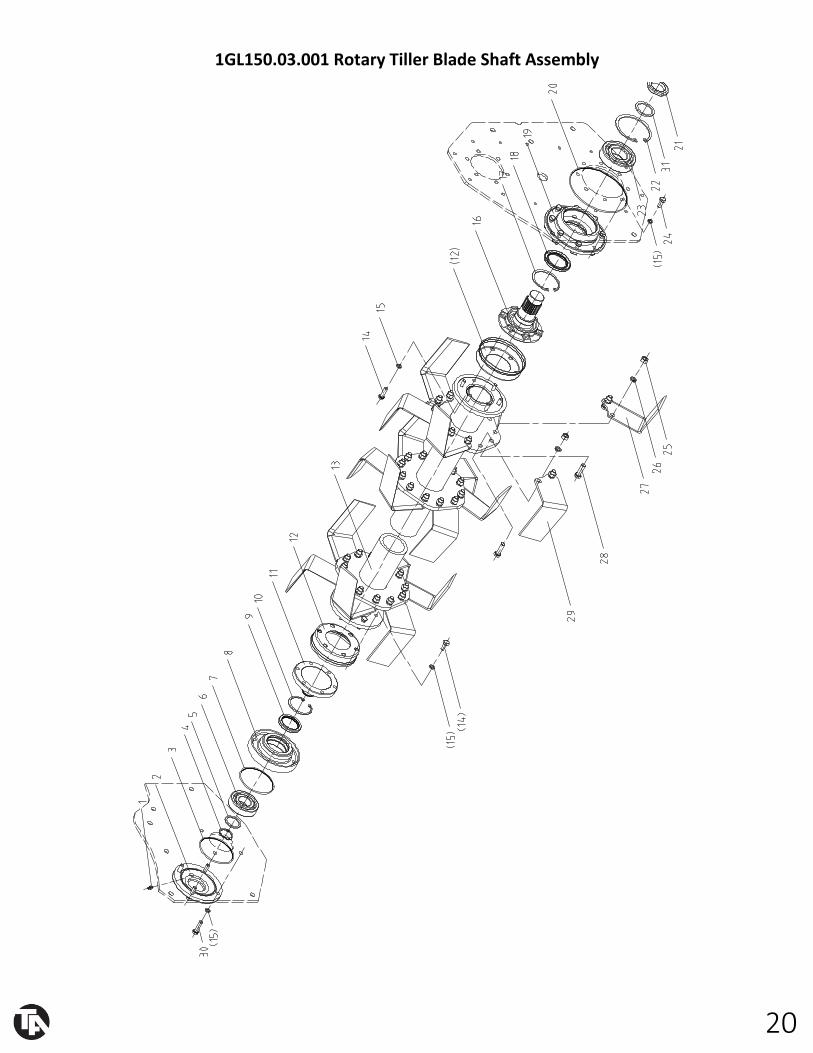
1GL150.03.001 Rotary Tiller Blade Shaft Assembly

21
1GL150.03.001 Rotary Tiller Blade Shaft Assembly Parts List
REF PART NUMBER DESCRIPTION QTY
1 JB/T7940.1-1995 Oil cup M8*1 1
2 1GN230.03.101 Side cover 1
3 GB/T3452.1-1992 O-ring 112*3.55 1
4 GB/T894.1-1986 Circlip 40 1
5 1GN230.03.103 Washer(L) 1
6 GB/T276-1994 Bearing 6308 1
7 GB/T3452.1-1992 O-ring 106*3.55 1
8 1GN230.03.102 Outer side support 1
9 GB/T13871-1992 Oil seal FB55*72*8 1
10 GB/T893.1-1986 Circlip 72 1
11 1GN230.03.104 Outer side hub 1
12 1GN230.03.105 Exterior dust cover 2
13 1GL155.03.011 Blades holder rotor 1
14 GB/T5783-2000 Bolt M10*35 8
15 GB/T93-1987 Spring washer 10 16
16 1GN230.03.107 Drive side hub 1
17 GB/T893.1-1986 Circlip 85 1
18 GB/T13871-1992 Oil seal FB60*85*8 1
19 1GN230.03.106 Drive side support 1
20 GB/T3452.1-1992 O-ring 185*3.55 1
21 GB/T812-1988 Self locking nut M45*1.5 1
22 GB/T893.1-1986 Circlip 110 1
23 GB/T276-1994 Bearing 6310 1
24 GB/T5783-2000 Bolt M10*25 4
25 GB/T889.1-2000 Nut M12 72
26 GB/T93-1987 Spring washer 12 72
27 1G135.01.102 Left helicoidal blade 18
28 GB/T5783-2000 Bolt M12*40 72
29 1G135.01.101 Right helicoidal blade 18
30 GB/T5783-2000 Bolt M10*40 4
31 GB/T858-1988 Self locking nut 45 1
22
This concludes the RT
Owner’s Manual.
Make sure to tighten all
nut-and-bolt
combinations before use.
Enjoy!
NEED HELP?
CONTACT US FIRST.
1 (800) 605-8241
Business Hours: Monday–Friday • 8:00 a.m.–5:00 p.m. (CT)