Embed Size (px)
Citation preview

MPQ Manufacturing Programmer
User's Guide
March, 2016
RPM Systems CorporationRedmond, Washington, USA
(425)869-3901 www.rpmsys.com
• MPQ-PSoC
• MPQ-Z8
• MPQ-C2
• MPQ-AVR
• MPQ-AVR32
• MPQ-ARM
RPM Systems Corporation March, 2016 Page 2
MPQ Manufacturing Programmer User's Guide
Contents
1. MPQ Overview ............................................................................................................ 5
1.1 MPQ Connections ......................................................................................................................... 5
1.2 Programming Images ..................................................................................................................... 5
2. MPQ Setup and Operation ......................................................................................... 7
2.1 Installing the MP Manager Software ........................................................................................... 7
2.2 Connecting MPQ Power and Communications ............................................................................ 72.2.1 Using a USB to Serial Communications Adapter with MPQ ..................................................... 7
2.3 Starting MP Manager Software and Connecting to MPQ .......................................................... 7
2.4 Loading Image Files into MPQ Flash ........................................................................................... 82.4.1 Selecting Programming Parameters ........................................................................................... 92.4.2 Multiple Files ......................................................................................................................... 112.4.3 Projects ................................................................................................................................. 112.4.4 Security Settings .................................................................................................................... 122.4.5 Serialization ........................................................................................................................... 12
2.5 Deleting Images from Programmer Flash .................................................................................. 14
2.6 Programming Devices from MP Manager ................................................................................. 142.6.1 Enabling and Disabling Target Ports ....................................................................................... 162.6.2 Verifying Devices ................................................................................................................... 162.6.3 Programming Errors ............................................................................................................... 162.6.4 CRC or Checksum Verify ..................................................................................................... 16
2.6.5 Programming Options ............................................................................................................... 16
2.7 Reading Images from Target Devices ....................................................................................... 17
2.8 Uploading Images from MPQ ..................................................................................................... 18
2.9 Array Programming from MP Manager ..................................................................................... 18
3.0 Stand-alone Device Programming ......................................................................... 20
3.1 Default Image and Port Enable Selections ................................................................................. 20
4.0 Interfacing MPQ with Automated Test Equipment ............................................. 22
4.1 Control Connector Signal Description ........................................................................................ 224.1.1 Active# Control ..................................................................................................................... 22
4.1.2 ATE Pass/Fail Status ................................................................................................................ 244.1.3 ATE OptionSelection ............................................................................................................. 244.1.4 ATE Option Setup ................................................................................................................. 24
RPM Systems Corporation March, 2016 Page 3
MPQ Manufacturing Programmer User's Guide
5.0 MPQ Arrays ............................................................................................................. 26
5.1 Stand-Alone Arrays ..................................................................................................................... 26
5.2 ATE Controlled Arrays ............................................................................................................... 26
5.3 PC-Controlled Arrays .................................................................................................................. 26
Appendix A - Cypress PSoC and enCoRe Microcontrollers .................................... 28
A.1 Device Options ............................................................................................................................ 28A.1.1 Device Type ......................................................................................................................... 28A.1.2 Target Voltage ...................................................................................................................... 29A.1.3 Mode ................................................................................................................................... 29
A.2 Programming Options ................................................................................................................. 29
A.3 PSoC Target Cable Connections ................................................................................................ 29
Appendix B - Zilog Z8 Encore! and ZLF645 .............................................................. 31
B.1 Device Options ............................................................................................................................ 31B.1.1 Device Family and Type ........................................................................................................ 31B.1.2 Target Voltage ...................................................................................................................... 32B.1.3 Mode ................................................................................................................................... 32B.1.4 Target Frequency .................................................................................................................. 32B.1.5 Special Considerations for 8-pin and Crimzon Parts ............................................................... 32
B.2 Programming Options ................................................................................................................. 32
B.3 - Target Cable Connections ........................................................................................................ 33
Appendix D - Silicon Labs C2 Microcontrollers ........................................................ 35
D.1 Device Options ........................................................................................................................... 35D.1.1 Device Type ......................................................................................................................... 35D.1.2 Target Voltage ...................................................................................................................... 36D.1.3 Mode ................................................................................................................................... 36
D.2 Programming Options ................................................................................................................. 36
D.3 Silicon Labs C2 Target Cable Connections ............................................................................... 36
Appendix F - Atmel AVR ................................................................................................ 38
F.1 Device Options ............................................................................................................................ 38F.1.1 Device Type .......................................................................................................................... 38F.1.2 Target Voltage ...................................................................................................................... 38F.1.3 Mode .................................................................................................................................... 38F.1.4 Target Frequency .................................................................................................................. 39F.1.5 SPI/JTAG Protocol Select ..................................................................................................... 39
F.2 Programming Options .................................................................................................................. 39F.2.1 Fuse Values .......................................................................................................................... 40
RPM Systems Corporation March, 2016 Page 4
MPQ Manufacturing Programmer User's Guide
F.2.2 EEPROM Programming ........................................................................................................ 40F.2.3 OSCCAL Programming ........................................................................................................ 41
F.3 - Target Cable Connections ........................................................................................................ 41
Appendix G - Atmel AVR32 ........................................................................................... 44
G.1 Device Options ........................................................................................................................... 44G.1.1 Device Type ......................................................................................................................... 44G.1.2 Target Voltage ...................................................................................................................... 44G.1.3 Mode ................................................................................................................................... 45
G.2 Programming Options ................................................................................................................. 45G.2.1 Fuse Values .......................................................................................................................... 45G.2.2 User Memory Programming .................................................................................................. 46G.2.3 Security Bit Programming ..................................................................................................... 47
G.3 - Target Cable Connections ....................................................................................................... 47
RPM Systems Corporation March, 2016 Page 5
MPQ Manufacturing Programmer User's Guide
1. MPQ Overview
The MPQ Manufacturing Programmer is a four port device programmer for In System Programming(ISP) of microcontrollers. MPQ allows you to:
• program up to four devices simultaneously from one MPQ• build arrays of up to 16 MPQ programmers to program up to 64 devices simultaneously• store up to four different device images in programmer Flash• use stand-alone (push-button), PC-controlled or ATE (Automated Test Equipment)-controlledmodes of operation• accommodate target device voltages from 1.6 to 5.5V
1.1 MPQ Connections
The MPQ has three external connectors: the Power connector, the Control connector and the Targetconnector. The Control connector is a 25-pin Female D Subminiature connector through which external controlof MPQ operations takes place. A Communications Cable is provided with the MPQ, which provides aconnection between its Control port and a host PC serial port for communications with the MP Managersoftware.
The Target connector is a 30-pin 2mm male header which provides programming signals for up to fourtarget devices. The Power connector is a 2.1mm male barrel connector, through which the MPQ itself ispowered. A Target Cable assembly is provided with MPQ which connects its Target port to the circuitboard(s) containing the ISP devices to be programmed. RPM offers several termination options for the targetend of Target Cables depending upon the particular microcontroller being supported. Target connector optionsand pin assignments are outlined in the appendices of this manual.
MPQ senses the target system power supply voltage on each of the four ports to determine when targetvoltage is at acceptable levels for programming. The MPQ does not provide power to the target systems. Thepower drawn by the MPQ from each target system for target voltage sensing is less than 1mA.
A power supply is provided with the MPQ, which plugs directly into the MPQ's Power connector, andwhich is capable of operation from any 50/60Hz, 100 ~ 240VAC power source.
1.2 Programming Images
Images to be programmed into the target devices are stored in the MPQ's internal Flash memory. Up tofour different images can be stored in the MPQ. Images are loaded into MPQ flash from a file on the host PC,or by reading a programmed device, using the MP Manager software provided with the MPQ. Additionalinformation required to program the target device, such as device type, target voltage and programming mode,is provided by the operator at the time each image is loaded, and is stored with the image in the programmer.Once an image is loaded into flash and the programmer's Target Cable is connected to the target systems,programming can be initiated in one of three ways: by pushing the green button on the top of the MPQ box(stand-alone mode), by asserting the Active# line on the Control connector (ATE mode), or on command from

RPM Systems Corporation March, 2016 Page 6
MPQ Manufacturing Programmer User's Guide
the MP Manager host software (PC-controlled mode).
While programming is in progress, the MPQ's Active LED will be lit. Upon completion of programming,the Active LED will be doused, and completion status for each of the four ports will be displayed on the Pass/Fail status LEDs. Disabled ports will not display LED pass/fail status.
RPM Systems Corporation March, 2016 Page 7
MPQ Manufacturing Programmer User's Guide
2. MPQ Setup and Operation
Before any devices can be programmed, the MPQ must be configured and target images loaded into itsinternal Flash memory.
2.1 Installing the MP Manager Software
MP Manager software is provided on the CD-ROM included with the MPQ. It can also be downloadedfrom the RPM Systems web site at: http://www.rpmsys.com/mpq.html. Minimum system requirements for MPManager operation are a 600MHz Pentium class computer with 64 MBytes of RAM, 40MBytes of availabledisk space and one available serial port. MP Manager is compatible with Microsoft Windows 98, WindowsNT, Windows 2000 and Windows XP operating systems.
To install MP Manager, insert the CD-ROM in the CD drive of the computer. If the installer does not startautomatically, browse to the MP Manager folder on the CD-ROM, and run the setup.exe file from that folder.Follow the on-screen instructions to complete installation of MP Manager on the computer. Once MP Managerhas been installed, it can be invoked from the Windows Start menu.
2.2 Connecting MPQ Power and Communications
Connect the MPQ-PS power supply provided with your MPQ to the programmer, and plug it into a 90 to240VAC, 50/60Hz power outlet. Then connect the Communications Cable, also provided, to the MPQControl connector, and to a 9-pin serial port on the PC host.
2.2.1 Using a USB to Serial Communications Adapter with MPQ
Many newer computers do not provide an RS-232 serial communications port, instead providing aUniversal Serial Bus (USB) standard port. Adapters are available which allow the USB port to be used tocommunicate with the MPQ's serial interface. If you wish to use a USB to seral adapter with your MPQ, pleasecontact RPM Systems for recommended products, or to purchase an adapter from us directly.
2.3 Starting MP Manager Software and Connecting to MPQ
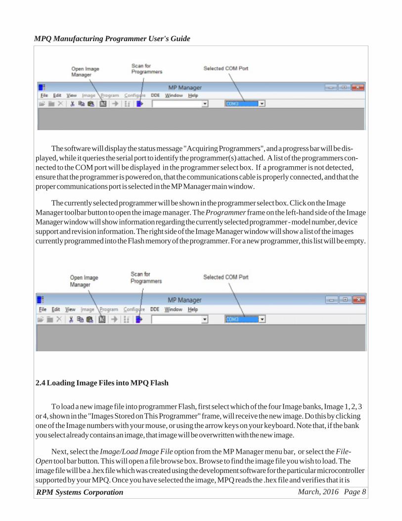
With MPQ powered on and connected the host PC as outlined in the previous section, start the MPManager software on the host PC (Start/MP Manager/MP Manager). In the main MP Manager window, selectthe communications port to which the MPQ is attached, then click the Scan for Programmers tool button tolocate and connect to programmers connected to that COM port.
RPM Systems Corporation March, 2016 Page 8
MPQ Manufacturing Programmer User's Guide
The software will display the status message "Acquiring Programmers", and a progress bar will be dis-played, while it queries the serial port to identify the programmer(s) attached. A list of the programmers con-nected to the COM port will be displayed in the programmer select box. If a programmer is not detected,ensure that the programmer is powered on, that the communications cable is properly connected, and that theproper communications port is selected in the MP Manager main window.
The currently selected programmer will be shown in the programmer select box. Click on the ImageManager toolbar button to open the image manager. The Programmer frame on the left-hand side of the ImageManager window will show information regarding the currently selected programmer - model number, devicesupport and revision information. The right side of the Image Manager window will show a list of the imagescurrently programmed into the Flash memory of the programmer. For a new programmer, this list will be empty.
2.4 Loading Image Files into MPQ Flash
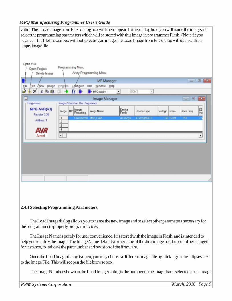
To load a new image file into programmer Flash, first select which of the four Image banks, Image 1, 2, 3or 4, shown in the "Images Stored on This Programmer" frame, will receive the new image. Do this by clickingone of the Image numbers with your mouse, or using the arrow keys on your keyboard. Note that, if the bankyou select already contains an image, that image will be overwritten with the new image.
Next, select the Image/Load Image File option from the MP Manager menu bar, or select the File-Open tool bar button. This will open a file browse box. Browse to find the image file you wish to load. Theimage file will be a .hex file which was created using the development software for the particular microcontrollersupported by your MPQ. Once you have selected the image, MPQ reads the .hex file and verifies that it is
RPM Systems Corporation March, 2016 Page 9
MPQ Manufacturing Programmer User's Guide
valid. The "Load Image from File" dialog box will then appear. In this dialog box, you will name the image andselect the programming parameters which will be stored with this image in programmer Flash. (Note: if you"Cancel" the file browse box without selecting an image, the Load Image from File dialog will open with anempty image file
name).
2.4.1 Selecting Programming Parameters
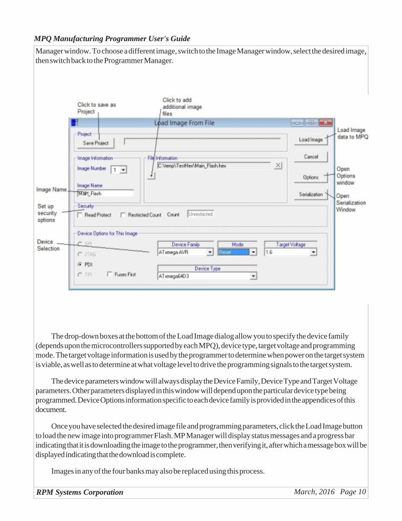
The Load Image dialog allows you to name the new image and to select other parameters necessary forthe programmer to properly program devices.
The Image Name is purely for user convenience. It is stored with the image in Flash, and is intended tohelp you identify the image. The Image Name defaults to the name of the .hex image file, but could be changed,for instance, to indicate the part number and revision of the firmware.
Once the Load Image dialog is open, you may choose a different image file by clicking on the ellipses nextto the Image File. This will reopen the file browse box.
The Image Number shown in the Load Image dialog is the number of the image bank selected in the Image
RPM Systems Corporation March, 2016 Page 10
MPQ Manufacturing Programmer User's Guide
Manager window. To choose a different image, switch to the Image Manager window, select the desired image,then switch back to the Programmer Manager.
The drop-down boxes at the bottom of the Load Image dialog allow you to specify the device family(depends upon the microcontrollers supported by each MPQ), device type, target voltage and programmingmode. The target voltage information is used by the programmer to determine when power on the target systemis viable, as well as to determine at what voltage level to drive the programming signals to the target system.
The device parameters window will always display the Device Family, Device Type and Target Voltageparameters. Other parameters displayed in this window will depend upon the particular device type beingprogrammed. Device Options information specific to each device family is provided in the appendices of thisdocument.
Once you have selected the desired image file and programming parameters, click the Load Image buttonto load the new image into programmer Flash. MP Manager will display status messages and a progress barindicating that it is downloading the image to the programmer, then verifying it, after which a message box will bedisplayed indicating that the download is complete.
Images in any of the four banks may also be replaced using this process.
RPM Systems Corporation March, 2016 Page 11
MPQ Manufacturing Programmer User's Guide
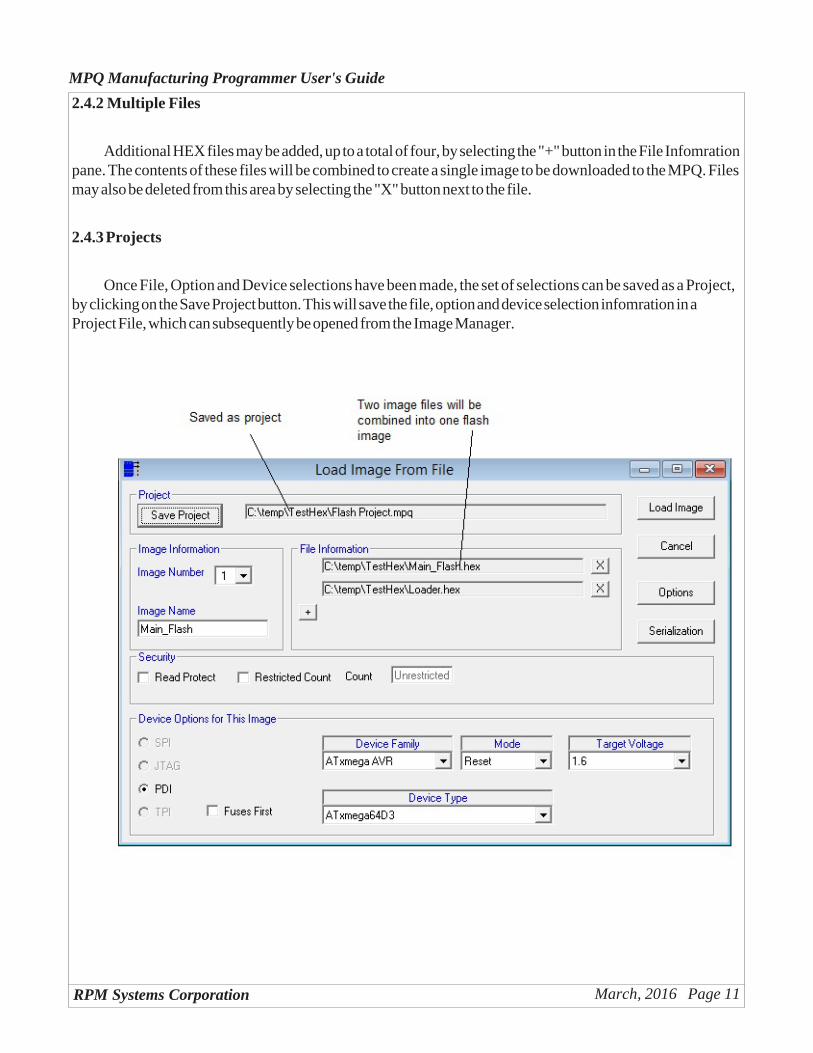
2.4.2 Multiple Files
Additional HEX files may be added, up to a total of four, by selecting the "+" button in the File Infomrationpane. The contents of these files will be combined to create a single image to be downloaded to the MPQ. Filesmay also be deleted from this area by selecting the "X" button next to the file.
2.4.3 Projects
Once File, Option and Device selections have been made, the set of selections can be saved as a Project,by clicking on the Save Project button. This will save the file, option and device selection infomration in aProject File, which can subsequently be opened from the Image Manager.
RPM Systems Corporation March, 2016 Page 12
MPQ Manufacturing Programmer User's Guide
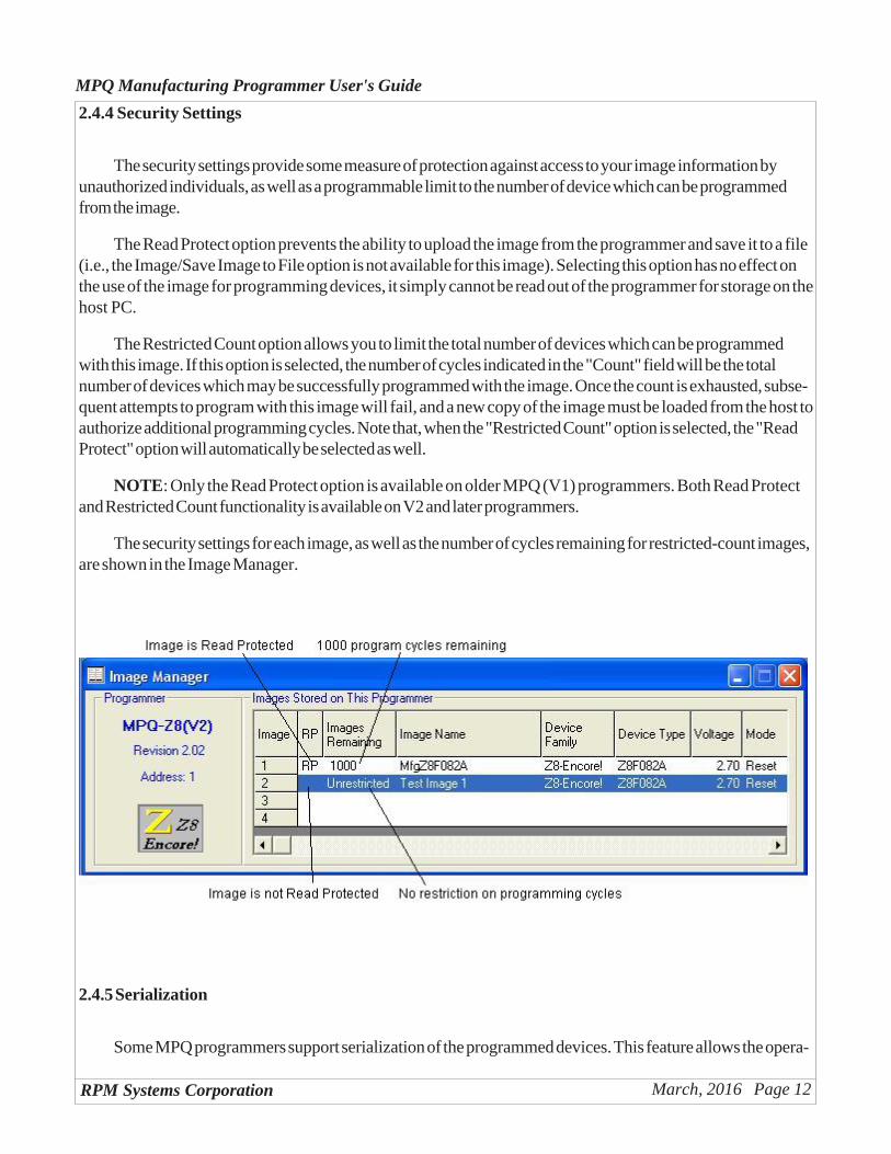
2.4.4 Security Settings
The security settings provide some measure of protection against access to your image information byunauthorized individuals, as well as a programmable limit to the number of device which can be programmedfrom the image.
The Read Protect option prevents the ability to upload the image from the programmer and save it to a file(i.e., the Image/Save Image to File option is not available for this image). Selecting this option has no effect onthe use of the image for programming devices, it simply cannot be read out of the programmer for storage on thehost PC.
The Restricted Count option allows you to limit the total number of devices which can be programmedwith this image. If this option is selected, the number of cycles indicated in the "Count" field will be the totalnumber of devices which may be successfully programmed with the image. Once the count is exhausted, subse-quent attempts to program with this image will fail, and a new copy of the image must be loaded from the host toauthorize additional programming cycles. Note that, when the "Restricted Count" option is selected, the "ReadProtect" option will automatically be selected as well.
NOTE: Only the Read Protect option is available on older MPQ (V1) programmers. Both Read Protectand Restricted Count functionality is available on V2 and later programmers.
The security settings for each image, as well as the number of cycles remaining for restricted-count images,are shown in the Image Manager.
2.4.5 Serialization
Some MPQ programmers support serialization of the programmed devices. This feature allows the opera-
RPM Systems Corporation March, 2016 Page 13
MPQ Manufacturing Programmer User's Guide
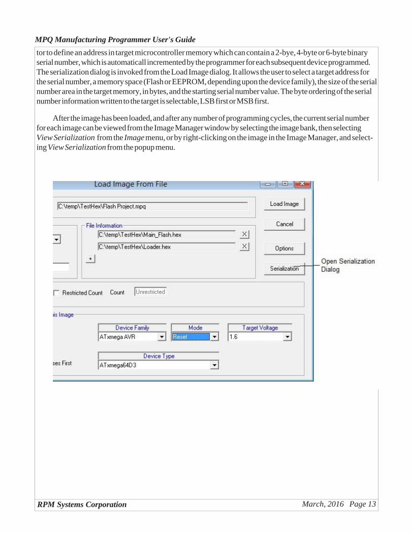
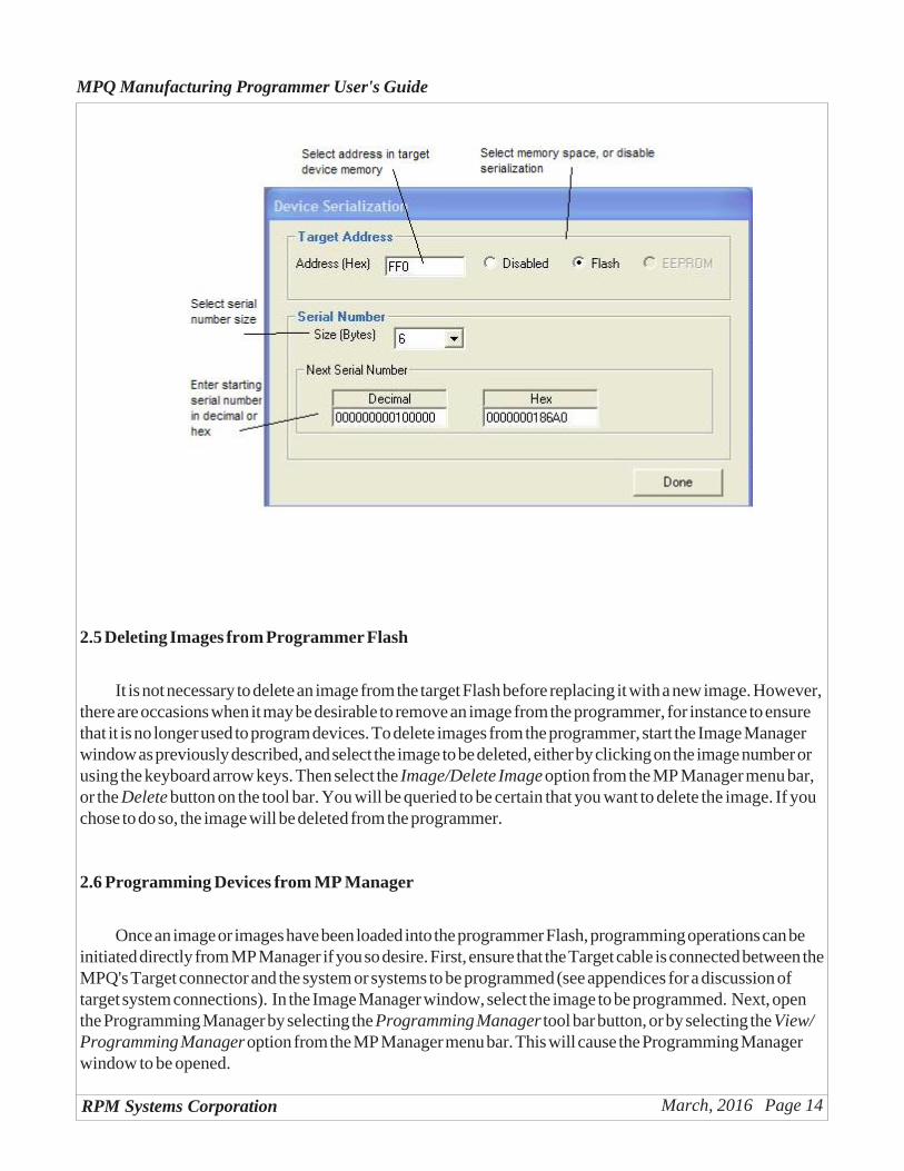
tor to define an address in target microcontroller memory which can contain a 2-bye, 4-byte or 6-byte binaryserial number, which is automaticall incremented by the programmer for each subsequent device programmed.The serialization dialog is invoked from the Load Image dialog. It allows the user to select a target address forthe serial number, a memory space (Flash or EEPROM, depending upon the device family), the size of the serialnumber area in the target memory, in bytes, and the starting serial number value. The byte ordering of the serialnumber information written to the target is selectable, LSB first or MSB first.
After the image has been loaded, and after any number of programming cycles, the current serial numberfor each image can be viewed from the Image Manager window by selecting the image bank, then selectingView Serialization from the Image menu, or by right-clicking on the image in the Image Manager, and select-ing View Serialization from the popup menu.
RPM Systems Corporation March, 2016 Page 14
MPQ Manufacturing Programmer User's Guide
2.5 Deleting Images from Programmer Flash
It is not necessary to delete an image from the target Flash before replacing it with a new image. However,there are occasions when it may be desirable to remove an image from the programmer, for instance to ensurethat it is no longer used to program devices. To delete images from the programmer, start the Image Managerwindow as previously described, and select the image to be deleted, either by clicking on the image number orusing the keyboard arrow keys. Then select the Image/Delete Image option from the MP Manager menu bar,or the Delete button on the tool bar. You will be queried to be certain that you want to delete the image. If youchose to do so, the image will be deleted from the programmer.
2.6 Programming Devices from MP Manager
Once an image or images have been loaded into the programmer Flash, programming operations can beinitiated directly from MP Manager if you so desire. First, ensure that the Target cable is connected between theMPQ's Target connector and the system or systems to be programmed (see appendices for a discussion oftarget system connections). In the Image Manager window, select the image to be programmed. Next, openthe Programming Manager by selecting the Programming Manager tool bar button, or by selecting the View/Programming Manager option from the MP Manager menu bar. This will cause the Programming Managerwindow to be opened.
RPM Systems Corporation March, 2016 Page 15
MPQ Manufacturing Programmer User's Guide
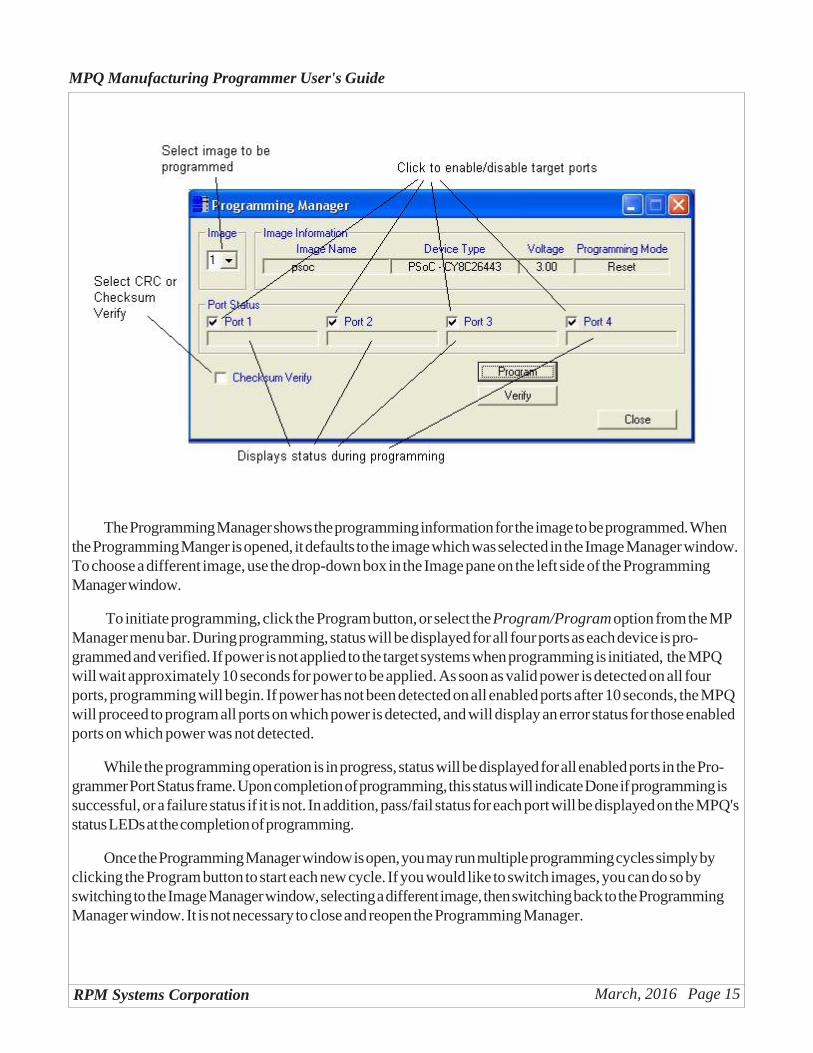
The Programming Manager shows the programming information for the image to be programmed. Whenthe Programming Manger is opened, it defaults to the image which was selected in the Image Manager window.To choose a different image, use the drop-down box in the Image pane on the left side of the ProgrammingManager window.
To initiate programming, click the Program button, or select the Program/Program option from the MPManager menu bar. During programming, status will be displayed for all four ports as each device is pro-grammed and verified. If power is not applied to the target systems when programming is initiated, the MPQwill wait approximately 10 seconds for power to be applied. As soon as valid power is detected on all fourports, programming will begin. If power has not been detected on all enabled ports after 10 seconds, the MPQwill proceed to program all ports on which power is detected, and will display an error status for those enabledports on which power was not detected.
While the programming operation is in progress, status will be displayed for all enabled ports in the Pro-grammer Port Status frame. Upon completion of programming, this status will indicate Done if programming issuccessful, or a failure status if it is not. In addition, pass/fail status for each port will be displayed on the MPQ'sstatus LEDs at the completion of programming.
Once the Programming Manager window is open, you may run multiple programming cycles simply byclicking the Program button to start each new cycle. If you would like to switch images, you can do so byswitching to the Image Manager window, selecting a different image, then switching back to the ProgrammingManager window. It is not necessary to close and reopen the Programming Manager.
RPM Systems Corporation March, 2016 Page 16
MPQ Manufacturing Programmer User's Guide
2.6.1 Enabling and Disabling Target Ports
Enable or disable target ports by checking or uncheck the boxes next to each target port in the Program-mer Port Status frame. A check mark in the box indicates that the port is enabled. It is not necessary to disableports that are not attached to a target system, however doing so does make the programming cycle go morequickly for the enabled ports, as the MPQ is not required to wait for the 10-second power time-out period toexpire.
2.6.2 Verifying Devices
All devices are verified immediately after programming during the Program cycle, before the security fusesare programmed. However, a separate verify-only cycle may be performed by clicking the Verify button in theProgramming Manager window, or by selecting the Program/Verify option from the MP Manager menu bar.Note that most microcontrollers contain security fuses which can be programmed to prevent subsequent readingof the device's program memory. If these fuses were programmed to setting other than "Unprotected" duringthe initial programming cycle, the device can not be read back, and VERIFY WILL FAIL.
2.6.3 Programming Errors
The following failure statuses may be reported in the Programmer Port Status frame:No Target Vcc No power was detected on the port within 10 seconds of program initiationDevice Timeout The device stopped responding during the program/verify sequenceVerify Failed Data read back from the device after programming was incorrectDevice ID Failed The device ID read from the device being programmed did not match the target
device type specified for the imageVCC Present Target Vcc was already present when a Power-On programming cycle was
initiated
2.6.4 CRC or Checksum Verify
When MPQ programs a device, it normally reads the entire device contents and compares it to the pro-gramming image in order to verify that the part was programmed correctly. The read-verify operation ensuresthat the programmed image is 100% correct, but lengthens the overall duration of the program cycle. Somemicrocontrollers, however, allow a CRC or checksum to be read from the device once it is programmed. MPQcan use this capability to reduce program cycle time by verifying that the device CRC or checksum matches thevalue expected for the programmed image. This allows a sometimes substantial time savings on each programcycle, with relatively little risk of not identifying improperly programmed devices. By checking the "CRC Verify"or "Checksum Verify" box in the Program Manager window, the operator can elect to have MPQ verifyprogramming by this method, rather than performing a complete read-verify.
2.6.5 Programming Options
Some devices offer programming options, such as memory protection features, oscillator selection, etc.,
RPM Systems Corporation March, 2016 Page 17
MPQ Manufacturing Programmer User's Guide
that must be selected at programming time. If the MPQ offers the ability to program these options for the devicebeing programmed, an "Options" button will be displayed in the Program Manager window. Clicking on theOptions button will open a second window which allows the available options to be selected. These optionwindows are discussed in detail in the appendix for each device family.
2.7 Reading Images from Target Devices
It is possible to read images from programmed target devices and store them in an image bank on theMPQ. This is useful if you desire to copy the contents of a given device for the purpose of programming otherdevices. NOTE that it is only possible to read a valid image from a device which has had its protection fusesprogrammed to prevent the reading of its internal memory. Images read from a device which has been pro-grammed for security will not be valid.
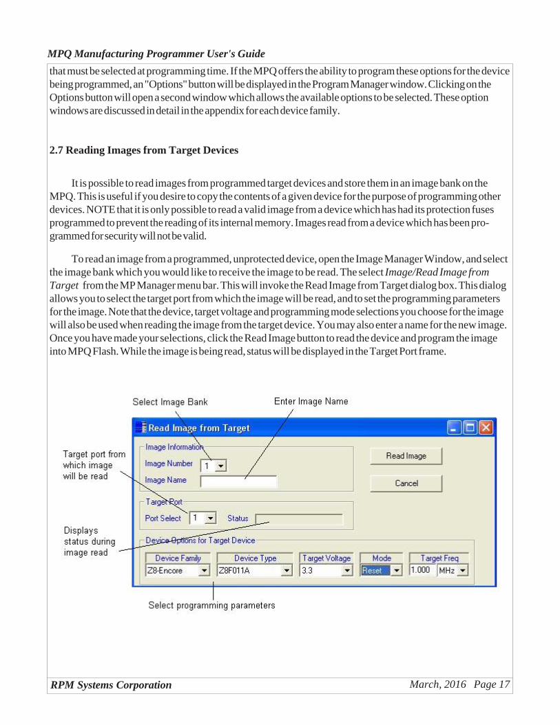
To read an image from a programmed, unprotected device, open the Image Manager Window, and selectthe image bank which you would like to receive the image to be read. The select Image/Read Image fromTarget from the MP Manager menu bar. This will invoke the Read Image from Target dialog box. This dialogallows you to select the target port from which the image will be read, and to set the programming parametersfor the image. Note that the device, target voltage and programming mode selections you choose for the imagewill also be used when reading the image from the target device. You may also enter a name for the new image.Once you have made your selections, click the Read Image button to read the device and program the imageinto MPQ Flash. While the image is being read, status will be displayed in the Target Port frame.
RPM Systems Corporation March, 2016 Page 18
MPQ Manufacturing Programmer User's Guide
2.8 Uploading Images from MPQ
An image stored in any of MPQ's four image banks may be uploaded and stored in a file on the host PC.To upload an image, open the Image Manager, select the image you would like to upload, then select Image/Save Image to File from the MP Manager menu bar. This will open a file browse box, allowing you to specifya file to receive the uploaded image. When you click Save in the Browse box, Image Manager will displaystatus and a progress bar as the image is uploaded from the programmer. The image will be stored on the PC asa standard Intel Hex file.
2.9 Array Programming from MP Manager
MPQ programmers can be connected together in arrays, allowing multiple programmers to be managedtogether, for simultaneous programming of up to 64 devices. Images are loaded into each MPQ, as describedpreviously, and the Array Program Manager is used to control the programming on multiple MPQ's simulta-neously. In order to access multiple MPQ's from the Array Program Manager, they must be interconnectedusing the RS-485 communications bus (see section 5 ), which allows multiple programmers to share a single PCcommunications port.
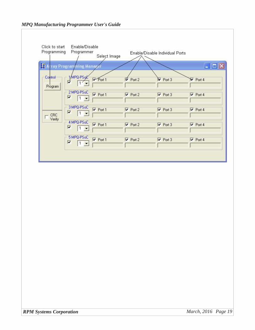
The first step in array programming is to load target images into all of the programmers in the array, usingthe Image Manager as previously described. Next, invoke the Array Program Manager using the toolbar button.In the Array Program Manager window, you will be presented with a list of all available programmers con-nected to the system (as determined by the last Scan for Programmers operation). You will be able to selectwhich programmers will be included in the array programming operation by clicking the check box on the leftside of each programmer frame. You will also be able to enable or disable individual ports on each programmer,just as you can from the Programming Manager. Finally, you will be able to select the desired image bank foreach programmer. Once you have selected the desired parameters, simply click the Program button to initiateprogramming of the entire array.
RPM Systems Corporation March, 2016 Page 19
MPQ Manufacturing Programmer User's Guide
RPM Systems Corporation March, 2016 Page 20
MPQ Manufacturing Programmer User's Guide
3.0 Stand-alone Device Programming
Once MP Manager has been used to load an image or images into the MPQ's internal Flash, devices maybe programmed without the need for a host PC connection. First, use MP Manager to load images into pro-grammer Flash, and to make default image and port enable selections as described in the following section.MPQ may then be disconnected from the host PC and used in stand-alone operation.
For stand-alone operation, provide power to the MPQ using the MPQ-PS power supply, and connect theTarget cable to the target system(s). A programming cycle is initiated by pressing the green button on the MPQ.The programming steps taken by the MPQ are identical in stand-alone mode to those taken in PC-connectedmode. Final programming status will be displayed on the status LEDs upon completion of programming. Instand-alone mode, without the host PC connected for detailed error reporting, only the LED pass/fail status isavailable.
Stand-alone operation can also be used with MPQ arrays to program up to 64 devices simultaneously.MPQ arrays are discussed in Section 5.
3.1 Default Image and Port Enable Selections
To prepare the MPQ for stand-alone ("push-button") operation, MP Manager must be used to select adefault programming image and port-enable selection. To select these options, invoke the Programming Man-ager, and select the image number and the port-enables you would like to have enabled during stand-aloneoperation, just as if you were preparing to program from MPManager. For those device families which supportCRC Verify or Checksum Verify, this option should also be selected at this time if it is desired for stand-aloneprogramming.
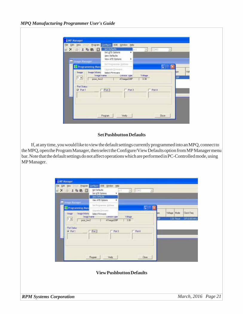
Once you have selected the desired image and port-enable parameters for stand-alone operation, selectConfigure/Set Defaults from the MP Manager menu bar. This will cause your selections to be loaded andstored in the MPQ, and used as the default settings for stand-alone operations.
RPM Systems Corporation March, 2016 Page 21
MPQ Manufacturing Programmer User's Guide
Set Pushbutton Defaults
If, at any time, you would like to view the default settings currently programmed into an MPQ, connect tothe MPQ, open the Program Manager, then select the Configure/View Defaults option from MP Manager menubar. Note that the default settings do not affect operations which are performed in PC-Controlled mode, usingMP Manager.
View Pushbutton Defaults
RPM Systems Corporation March, 2016 Page 22
MPQ Manufacturing Programmer User's Guide
4.0 Interfacing MPQ with Automated Test Equipment
The Control connector provides signals which can be used by Automated Test Equipment (ATE) tomanage device programming using the MPQ. ATE control can be extremely simple, involving the use of onlyone logic-level signal. Additional logic signals may be used to provide the ATE with the capability to selectdifferent image and port selection options, and to monitor pass/fail status.
The ATE control signals work in conjunction with settings programmed into the MPQ by MPManager.The ATE may use the Default setting, described in the previous section, or one of four optional ATE settings.
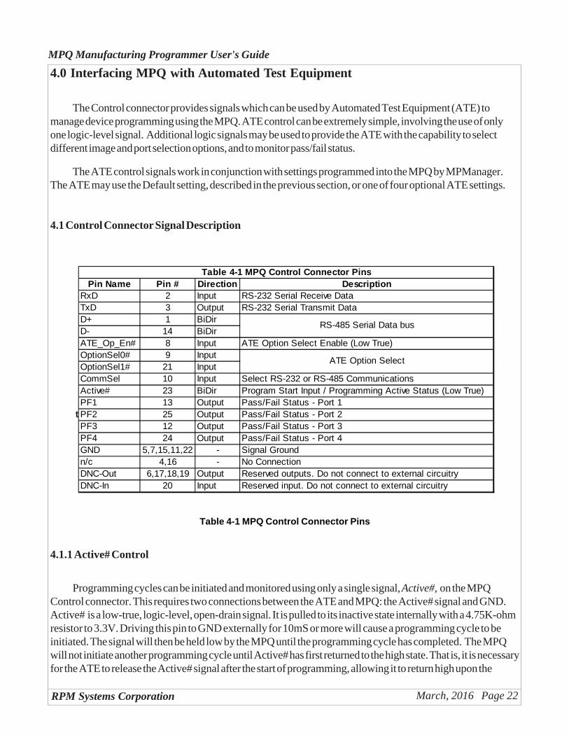
4.1 Control Connector Signal Description
t
Pin Name Pin # Direction DescriptionRxD 2 Input RS-232 Serial Receive DataTxD 3 Output RS-232 Serial Transmit DataD+ 1 BiDirD- 14 BiDirATE_Op_En# 8 Input ATE Option Select Enable (Low True)OptionSel0# 9 InputOptionSel1# 21 InputCommSel 10 Input Select RS-232 or RS-485 CommunicationsActive# 23 BiDir Program Start Input / Programming Active Status (Low True)PF1 13 Output Pass/Fail Status - Port 1PF2 25 Output Pass/Fail Status - Port 2PF3 12 Output Pass/Fail Status - Port 3PF4 24 Output Pass/Fail Status - Port 4GND 5,7,15,11,22 - Signal Groundn/c 4,16 - No ConnectionDNC-Out 6,17,18,19 Output Reserved outputs. Do not connect to external circuitryDNC-In 20 Input Reserved input. Do not connect to external circuitry
RS-485 Serial Data bus
ATE Option Select
Table 4-1 MPQ Control Connector Pins
Table 4-1 MPQ Control Connector Pins
4.1.1 Active# Control
Programming cycles can be initiated and monitored using only a single signal, Active#, on the MPQControl connector. This requires two connections between the ATE and MPQ: the Active# signal and GND.Active# is a low-true, logic-level, open-drain signal. It is pulled to its inactive state internally with a 4.75K-ohmresistor to 3.3V. Driving this pin to GND externally for 10mS or more will cause a programming cycle to beinitiated. The signal will then be held low by the MPQ until the programming cycle has completed. The MPQwill not initiate another programming cycle until Active# has first returned to the high state. That is, it is necessaryfor the ATE to release the Active# signal after the start of programming, allowing it to return high upon the
RPM Systems Corporation March, 2016 Page 23
MPQ Manufacturing Programmer User's Guide
completion of programming, before another programming cycle may be initiated. The programming cycle will berun on all enabled ports of the MPQ. The default image and port-enable information will be used for program-ming unless ATE image selection is employed (section 4.1.3).
Active# is an open-drain signal . Current should never be sourced into this pin by the ATE device, andthis pin should never be driven below GND potential.
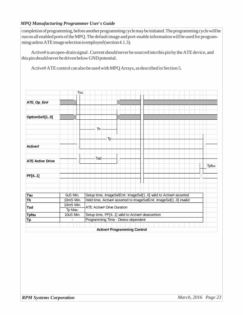
Active# ATE control can also be used with MPQ Arrays, as described in Section 5.
Tsu
ATE_Op_En#
OptionSell[1..0]
Active#
ATE Active DriveTpfsu
PF[4..1]
TsuTh
TpfsuTp
Hold time, Active# asserted to ImageSelEn#, ImageSel[1..0] invalid0uS Min.
10mS Min.
Tad10mS Min.
Active# Programming Control
-
Th
Tp
10uS Min. Setup time, PF[4..1] valid to Active# deassertion
Tad
ATE Active# Drive Duration
Programming Time - Device dependent
Tp Max.
Setup time, ImageSelEn#, ImageSel[1..0] valid to Active# asserted
RPM Systems Corporation March, 2016 Page 24
MPQ Manufacturing Programmer User's Guide
4.1.2 ATE Pass/Fail Status
At the completion of programming, pass/fail status is available on pins PF1 .. PF4 of the Control connec-tor. The pins will be drive high (~3.3V) by the MPQ to indicate a PASS condition, or low to indicate a FAILcondition. PF1..PF4 are valid on the rising edge of Active#.
The PF1..PF4 signals have an output resistance of approximately 100 ohms. Excessive loading on thesepins should be avoided, and they should not be driven by the ATE.
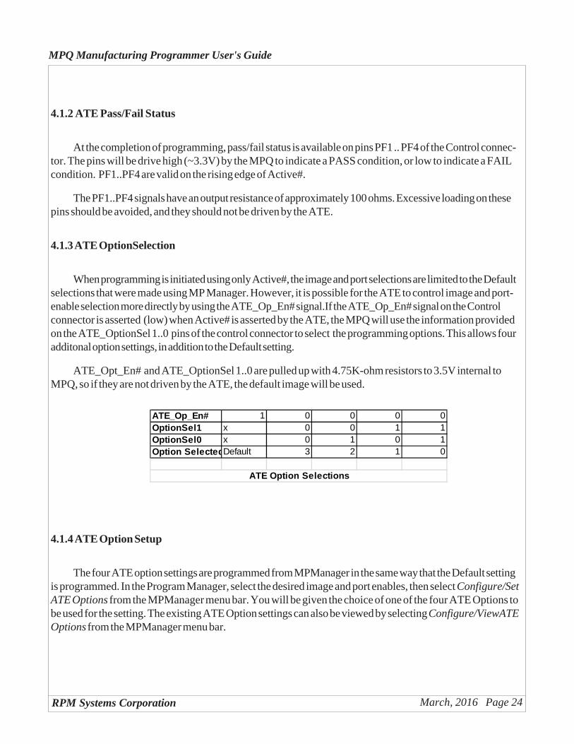
4.1.3 ATE OptionSelection
When programming is initiated using only Active#, the image and port selections are limited to the Defaultselections that were made using MP Manager. However, it is possible for the ATE to control image and port-enable selection more directly by using the ATE_Op_En# signal.If the ATE_Op_En# signal on the Controlconnector is asserted (low) when Active# is asserted by the ATE, the MPQ will use the information providedon the ATE_OptionSel 1..0 pins of the control connector to select the programming options. This allows fouradditonal option settings, in addition to the Default setting.
ATE_Opt_En# and ATE_OptionSel 1..0 are pulled up with 4.75K-ohm resistors to 3.5V internal toMPQ, so if they are not driven by the ATE, the default image will be used.
ATE_Op_En# 1 0 0 0 0OptionSel1 x 0 0 1 1OptionSel0 x 0 1 0 1Option SelectedDefault 3 2 1 0
ATE Option Selections
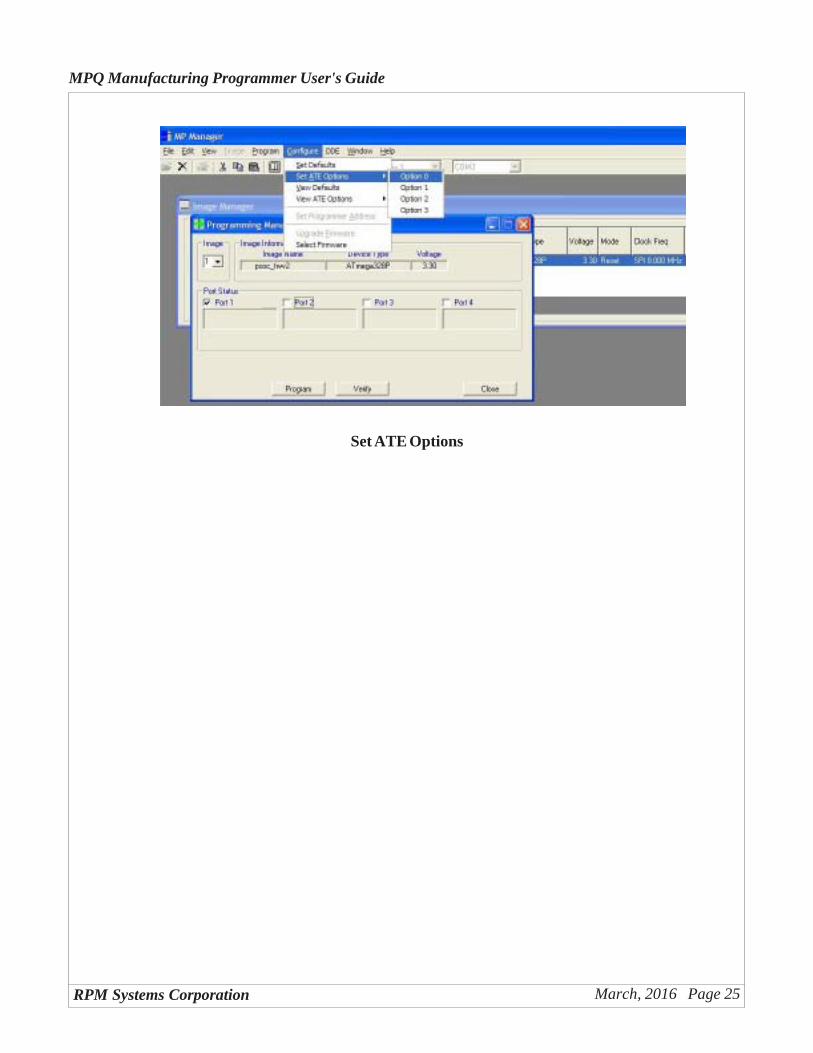
4.1.4 ATE Option Setup
The four ATE option settings are programmed from MPManager in the same way that the Default settingis programmed. In the Program Manager, select the desired image and port enables, then select Configure/SetATE Options from the MPManager menu bar. You will be given the choice of one of the four ATE Options tobe used for the setting. The existing ATE Option settings can also be viewed by selecting Configure/ViewATEOptions from the MPManager menu bar.
RPM Systems Corporation March, 2016 Page 25
MPQ Manufacturing Programmer User's Guide
Set ATE Options
RPM Systems Corporation March, 2016 Page 26
MPQ Manufacturing Programmer User's Guide
5.0 MPQ Arrays
MPQ programmers can be arranged in arrays - essentially networked together- in a variety of ways inorder to provide the ability to control all the programmers in the array with one set of control inputs. Arrays canbe used in Stand-alone, ATE and PC-Controlled operating modes.
5.1 Stand-Alone Arrays
To use stand-alone MPQ arrays, it is necessary only to connect together the GND and Active# signals ofall programmers in the array. Pressing the green programming button on any one of the MPQs will then initiate aprogramming cycle on all MPQs in the array. Each MPQ will display pass/fail status for its four ports on its ownPass/Fail LED displays. Under normal circumstances, the image and port enables selected for the array opera-tion will be the Default image selected for each programmer by MP Manager (section 3.1), however the ATEcontrol signals can also be used to select different programming options, as described in the preceding sectionon ATE-controlled progamming.
5.2 ATE Controlled Arrays
ATE controlled arrays can be constructed by connecting together the GND and Active# signals of allprogrammers in the array. The ATE may then drive the shared Active# low to initiate a programming cycle onall programmers in the array. Note that, since each MPQ provides an internal 4.75K-ohm pullup resistor, theamount of current required from the ATE to assert the Active# signal increases with the number of programmersin the array. The minimum sink current required to assert Active# in an array of 16 programmers is approxi-mately 10mA.
Once the programming cycle is initiated, Active# will be held low until all programmers in the array havecompleted their programming cycles.
If ATE image selection is desired, the ATE_Op_En# and OptionSel1..0 signals of the programmers in thearray may be interconnect, as well, and driven by the ATE as described in section 4.1.3.
If the ATE needs to acquire pass/fail status from the programmers in the array, the PF1..4 status outputsfrom each MPQ in the array must be acquired independently - as a separate ATE input - as each output appliesto a specific target port.
5.3 PC-Controlled Arrays
In order to control arrays from the PC, using MP Manager, the PC must be able to communicate with allof the programmers in the array. This is enabled by using the MPQ's built-in RS-485 communications bus.Essentially, the D+, D- and GND signals of each of the programmers in the array are connected together with

RPM Systems Corporation March, 2016 Page 27
MPQ Manufacturing Programmer User's Guide
the D+, D- and GND signals, respectively, of the other programmers in the array. This is facilitated by the useof the USB Array Interconnect Board, RPM p/n MPQ-AIB-USB, which provides the RS-485 interconnectcapability via ribbon cable connectors, as well as an RS-485 to USB interface converter, which allows theentire array to be directly controlled from a standard PC USB port.
It should be noted that the Active# lines of the multiple programmers should not be connected together inPC-controlled arrays, as they are in stand-alone or ATE-controlled arrays. In PC-controlled arrays, the pro-gramming cycle is initiated and monitored on each programmer independently by MP Manager.
RPM Systems Corporation March, 2016 Page 28
MPQ Manufacturing Programmer User's Guide
Appendix A - Cypress PSoC and enCoRe Microcontrollers
This appendix provides details of connection and operation of the MPQ programmer for Cypress Semi-conductor PSoC microcontrollers.
A.1 Device Options
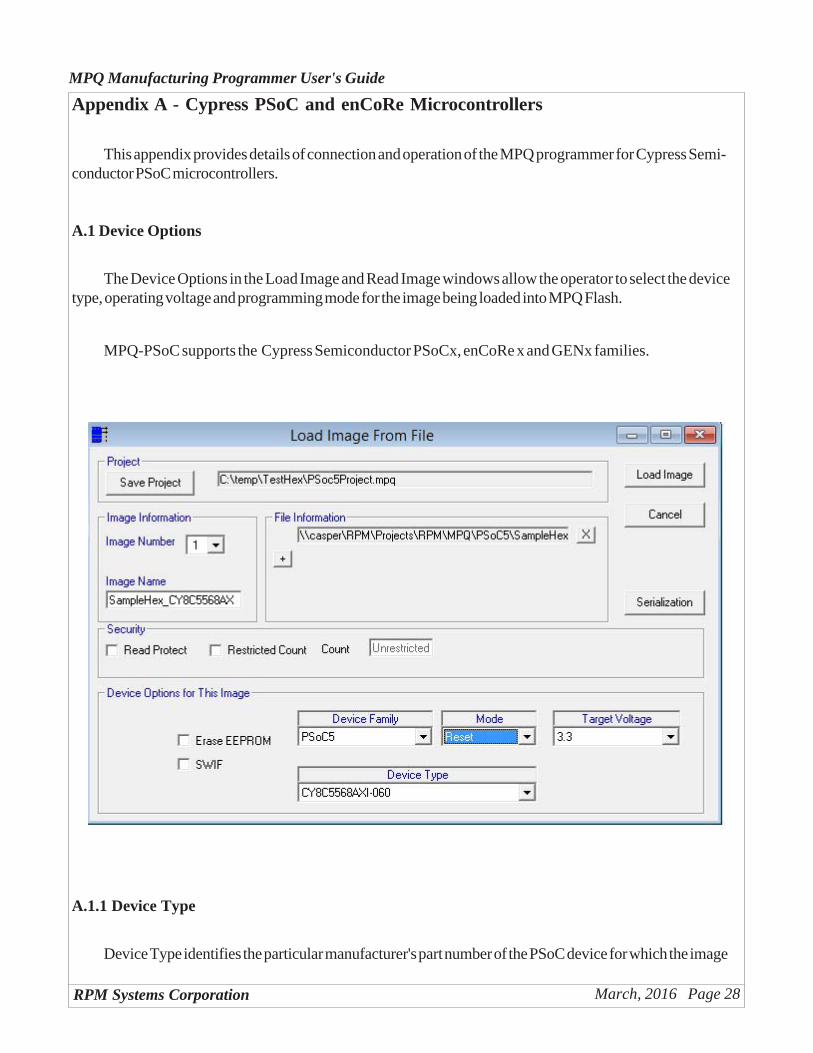
The Device Options in the Load Image and Read Image windows allow the operator to select the devicetype, operating voltage and programming mode for the image being loaded into MPQ Flash.
MPQ-PSoC supports the Cypress Semiconductor PSoCx, enCoRe x and GENx families.
A.1.1 Device Type
Device Type identifies the particular manufacturer's part number of the PSoC device for which the image
RPM Systems Corporation March, 2016 Page 29
MPQ Manufacturing Programmer User's Guide
being loaded is intended. Select the proper device from the dropdown list. MPQ will use this information priorto programming to verify the device ID in the part to be programmed.
A.1.2 Target Voltage
Select the voltage at which the target system will be operating during the programming of the device. MPQwill use this information to verify that the target power is at the proper level before beginning the programmingoperation.
A.1.3 Mode
Cypress PSoC devices can be programmed in either of two modes, Reset mode or Power-on mode. 8-pin devices only support the power-on mode. Unless you are using an 8-pin device, or have a specific reason touse Power-on mode (e.g., the CPU Reset signal is not wired on the programming connector), RPM recom-mends the use of Reset mode. Power-on mode requires that target system power be off at the start of eachprogramming cycle. Reset programming mode will function whether programming is initiated with target poweron or off.
In Power-on programming mode, a power cycle is required to gain control of the target devices forprogramming. In this case, if power is detected on an enabled port when programming is initiated, programmingwill fail. The target system(s) must be powered off before starting the programming cycle. The following stepsare taken during the programming cycle:
• verify target power off (Power-On programming only)• wait for target power valid• program devices• verify devices• program security bits
A.2 Programming Options
MPQ-PSoC provides two programming options, depending upon the particular device family. The EraseEEPROM option causes the device EEPROM to be erased as part of the programming cycle, for those devicesfor which this is an option. The SWIF option indicates that the programming operation uses the RPM SIWFpower-switching board. The setting of the memory protection bits is defined by the Cypress PSoC Develop-ment Tools, and stored in the program image produced by that software.
A.3 PSoC Target Cable Connections
The Target Cable assembly provides the connection between the programmer and the four target boards.The Target Cable provides connections to the standard 5-pin Molex connector used by Cypress Semiconduc-tor on their development and programming boards (Molex P/N 22-23-2051). The customer may request an
RPM Systems Corporation March, 2016 Page 30
MPQ Manufacturing Programmer User's Guide
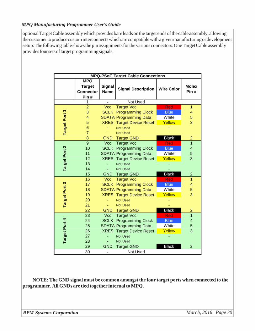
optional Target Cable assembly which provides bare leads on the target ends of the cable assembly, allowingthe customer to produce custom interconnects which are compatible with a given manufacturing or developmentsetup. The following table shows the pin assignments for the various connectors. One Target Cable assemblyprovides four sets of target programming signals.
MPQ Target
Connector Pin #
Signal Name
Signal Description Wire ColorMolex Pin #
1 - Not Used2 Vcc Target Vcc Red 13 SCLK Programming Clock Blue 44 SDATA Programming Data White 55 XRES Target Device Reset Yellow 36 - Not Used -7 - Not Used -8 GND Target GND Black 29 Vcc Target Vcc Red 110 SCLK Programming Clock Blue 411 SDATA Programming Data White 512 XRES Target Device Reset Yellow 313 - Not Used -14 - Not Used -15 GND Target GND Black 216 Vcc Target Vcc Red 117 SCLK Programming Clock Blue 418 SDATA Programming Data White 519 XRES Target Device Reset Yellow 320 - Not Used -21 - Not Used -22 GND Target GND Black 223 Vcc Target Vcc Red 124 SCLK Programming Clock Blue 425 SDATA Programming Data White 526 XRES Target Device Reset Yellow 327 - Not Used -28 - Not Used
29 GND Target GND Black 230 - Not Used
Tar
get
Po
rt 4
MPQ-PSoC Target Cable Connections
Tar
get
Po
rt 1
Tar
get
Po
rt 2
Tar
get
Po
rt 3
NOTE: The GND signal must be common amongst the four target ports when connected to theprogrammer. All GNDs are tied together internal to MPQ.
RPM Systems Corporation March, 2016 Page 31
MPQ Manufacturing Programmer User's Guide
Appendix B - Zilog Z8 Encore! and ZLF645
This appendix provides details of connection and operation of the MPQ programmer for Zilog Z8 Encore!microcontrollers.
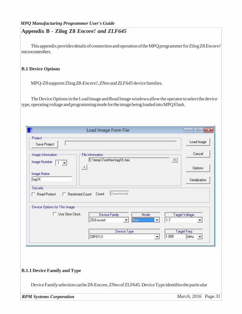
B.1 Device Options
MPQ-Z8 supports Zliog Z8-Encore!, ZNeo and ZLF645 device families.
The Device Options in the Load Image and Read Image windows allow the operator to select the devicetype, operating voltage and programming mode for the image being loaded into MPQ Flash.
B.1.1 Device Family and Type
Device Family selection can be Z8-Encore, ZNeo of ZLF645. Device Type identifies the particular
RPM Systems Corporation March, 2016 Page 32
MPQ Manufacturing Programmer User's Guide
device in that family for which the image being loaded is intended. Select the proper device from the dropdownlist. MPQ will use this information prior to programming to verify the device ID in the part to be programmed.
B.1.2 Target Voltage
Select the voltage at which the target system will be operating during the programming of the device. MPQwill use this information to verify that the target power is at the proper level before beginning the programmingoperation. The selection of target voltages available in the dropdown list will depend upon the particular deviceselected in "Device Type", so make the device type selection first.
B.1.3 Mode
There are two Mode selections available for Z8 Encore, "Reset" and "Run". The Mode selection deter-mines whether the target system will be held in reset at the completion of a program cycle ("Reset"), or be resetand then permitted to begin code execution ("Run").
B.1.4 Target Frequency
Enter the clock frequency of the target system as it will be when the device is being programmed. Thisinformation is used by the MPQ to determine the frequency of the programming clock, which is limited by thefrequency of the CPU clock in the target. Note that slower target clock frequencies will result in longer pro-gramming times. MPQ will support target clock frequencies as low as 32KHz, but it is recommended that thetarget clock frequency during programming be at least 1MHz in order to avoid excessively long programmingtimes.
B.1.5 Special Considerations for 8-pin and Crimzon Parts
Certain members of the Z8 Encore! and ZLF645 Crimzon family require special consideration during in-system programming. In particular, these parts do not provide an external Reset capability. They must thereforebe programmed starting from a power-off condition. That is, when programming is initiated from MPManageror from programmer hardware (ATE or push-button), target power must be off. Power must then be applied tothe target within 10 seconds of initiating programming.
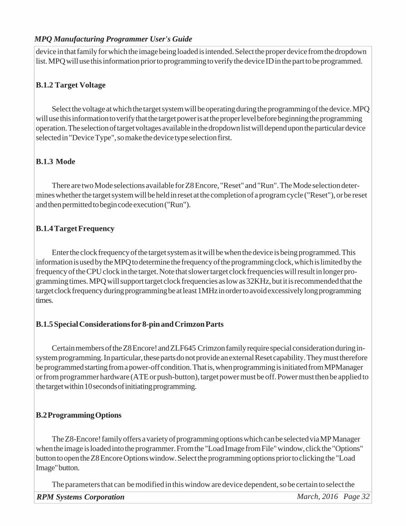
B.2 Programming Options
The Z8-Encore! family offers a variety of programming options which can be selected via MP Managerwhen the image is loaded into the programmer. From the "Load Image from File" window, click the "Options"button to open the Z8 Encore Options window. Select the programming options prior to clicking the "LoadImage" button.
The parameters that can be modified in this window are device dependent, so be certain to select the
RPM Systems Corporation March, 2016 Page 33
MPQ Manufacturing Programmer User's Guide
target device from the "Device Type" dropdown list before opening the Options window.
B.3 - Target Cable Connections
The Target Cable assembly provides the connection between the programmer and the four target boards.The Target Cable provides connections to the 6-pin DBG connector used by Zilog on their development andevaluation boards. The customer may optionally request bare leads on the target ends of the cable assembly,allowing the customer to produce custom interconnects which are compatible with a given manufacturing ordevelopment setup. The following table shows the pin assignments for the various connectors. One TargetCable assembly provides four sets of target programming signals.
RPM Systems Corporation March, 2016 Page 34
MPQ Manufacturing Programmer User's Guide
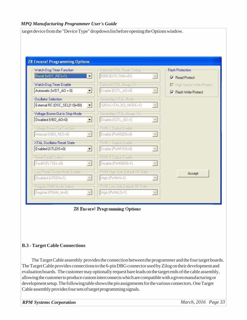
The following drawing shows the target system connections required for programming of devices on theZ8-Encore! target board using the MPQ. Connection of the RESET signal is optional but recommended.
MPQ Target
Connector Pin #
Signal Name
Signal Description Wire ColorZilog
DBG Pin #
1 - Not Used2 Vcc Target Vcc Red 13 - Not Used -4 DBG Target Debug signal Yellow 45 RESET Target Device Reset Violet 26 - Not Used -7 - Not Used -8 GND Target GND Black 39 Vcc Target Vcc Red 110 - Not Used -11 DBG Target Debug signal Yellow 412 RESET Target Device Reset Violet 213 - Not Used -14 - Not Used -15 GND Target GND Black 316 Vcc Target Vcc Red 117 - Not Used -18 DBG Target Debug signal Yellow 419 RESET Target Device Reset Violet 220 - Not Used -21 - Not Used -22 GND Target GND Black 323 Vcc Target Vcc Red 124 - Not Used -25 DBG Target Debug signal Yellow 426 RESET Target Device Reset Violet 227 - Not Used -28 - Not Used
29 GND Target GND Black 330 - Not Used
Tar
get
Po
rt 4
MPQ-Z8 Target Cable Connections
Tar
get
Po
rt 1
Tar
get
Po
rt 2
Tar
get
Po
rt 3
NOTE: The GND signal must be common amongst the four target ports when connected to theprogrammer. All GNDs are tied together internal to MPQ.
RPM Systems Corporation March, 2016 Page 35
MPQ Manufacturing Programmer User's Guide
Appendix D - Silicon Labs C2 Microcontrollers
This appendix provides details of connection and operation of the MPQ programmer for Silicon Labsmicrocontrollers using the C2 programming interface.
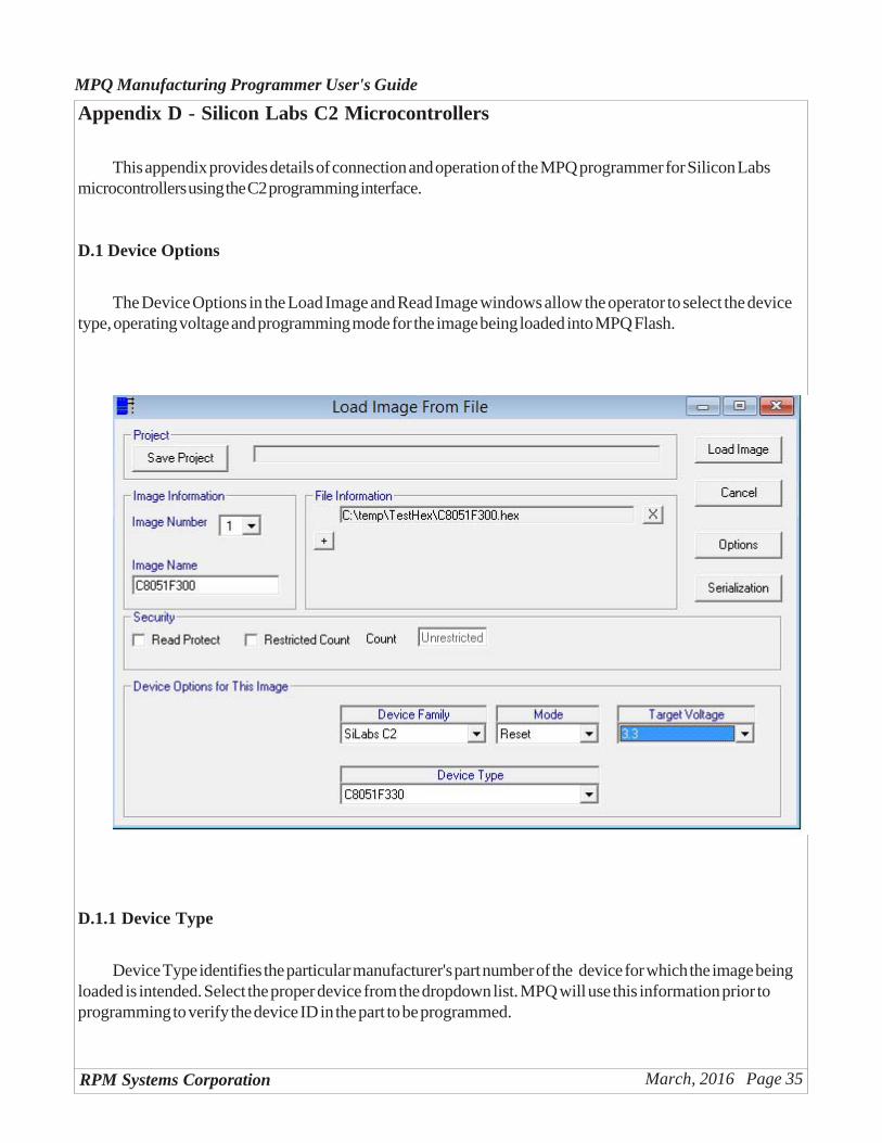
D.1 Device Options
The Device Options in the Load Image and Read Image windows allow the operator to select the devicetype, operating voltage and programming mode for the image being loaded into MPQ Flash.
D.1.1 Device Type
Device Type identifies the particular manufacturer's part number of the device for which the image beingloaded is intended. Select the proper device from the dropdown list. MPQ will use this information prior toprogramming to verify the device ID in the part to be programmed.
RPM Systems Corporation March, 2016 Page 36
MPQ Manufacturing Programmer User's Guide
D.1.2 Target Voltage
Select the voltage at which the target system will be operating during the programming of the device. MPQwill use this information to verify that the target power is at the proper level before beginning the programmingoperation.
D.1.3 Mode
There are two Mode selections available for MPQ-C2, "Reset" and "Run". The Mode selection deter-mines whether the target system will be held in reset at the completion of a program cycle ("Reset"), or be resetand then permitted to begin code execution ("Run").
D.2 Programming Options
No programming options are supported for the C8051F3xx family devices.
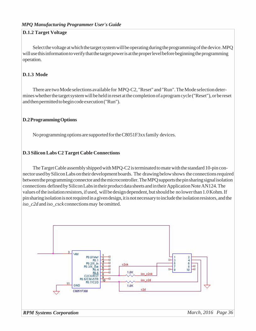
D.3 Silicon Labs C2 Target Cable Connections
The Target Cable assembly shipped with MPQ-C2 is terminated to mate with the standard 10-pin con-nector used by Silicon Labs on their development boards. The drawing below shows the connections requiredbetween the programming connector and the microcontroller. The MPQ supports the pin sharing signal isolationconnections defined by Silicon Labs in their product data sheets and in their Application Note AN124. Thevalues of the isolation resistors, if used, will be design dependent, but should be no lower than 1.0 Kohm. Ifpin sharing isolation is not required in a given design, it is not necessary to include the isolation resistors, and theiso_c2d and iso_csck connections may be omitted.
RPM Systems Corporation March, 2016 Page 37
MPQ Manufacturing Programmer User's Guide
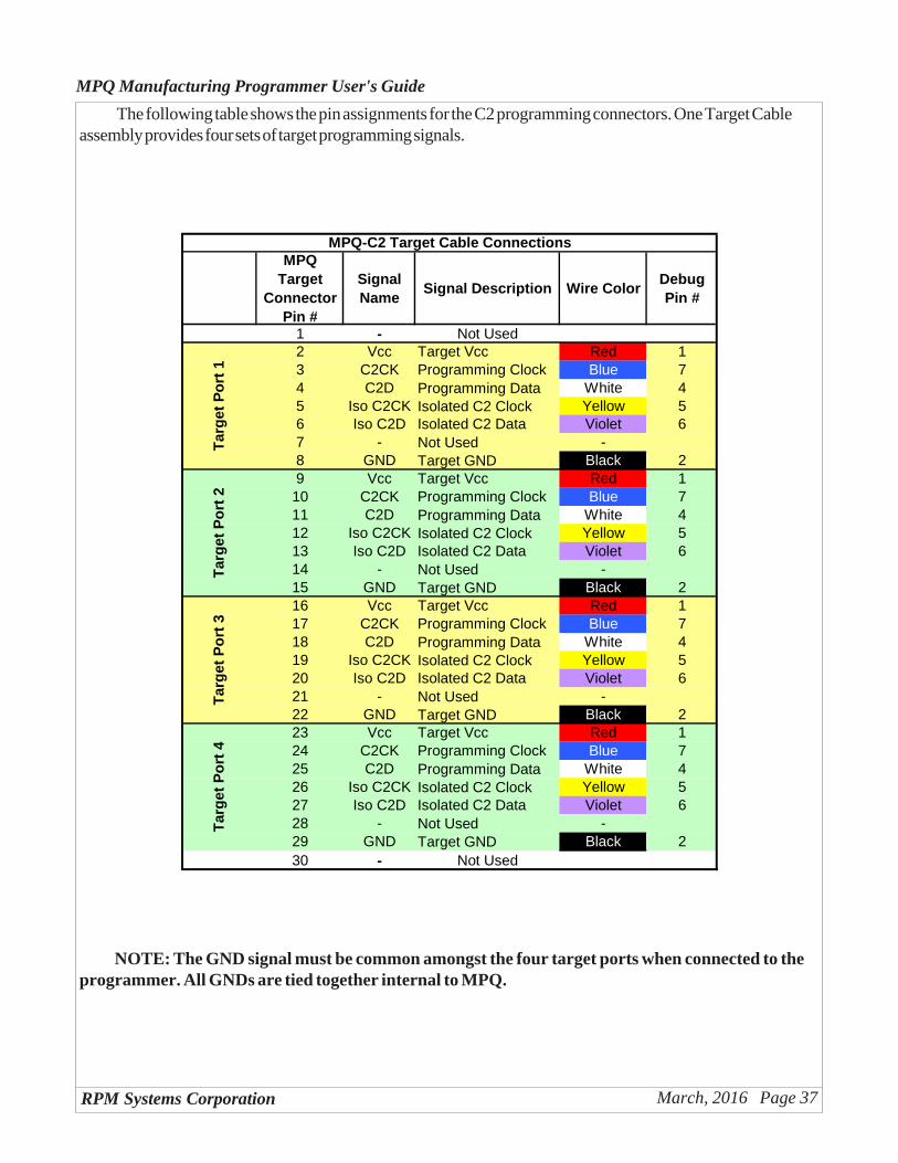
The following table shows the pin assignments for the C2 programming connectors. One Target Cableassembly provides four sets of target programming signals.
MPQ Target
Connector Pin #
Signal Name
Signal Description Wire ColorDebug Pin #
1 - Not Used2 Vcc Target Vcc Red 13 C2CK Programming Clock Blue 74 C2D Programming Data White 45 Iso C2CK Isolated C2 Clock Yellow 56 Iso C2D Isolated C2 Data Violet 67 - Not Used -8 GND Target GND Black 29 Vcc Target Vcc Red 110 C2CK Programming Clock Blue 711 C2D Programming Data White 412 Iso C2CK Isolated C2 Clock Yellow 513 Iso C2D Isolated C2 Data Violet 614 - Not Used -15 GND Target GND Black 216 Vcc Target Vcc Red 117 C2CK Programming Clock Blue 718 C2D Programming Data White 419 Iso C2CK Isolated C2 Clock Yellow 520 Iso C2D Isolated C2 Data Violet 621 - Not Used -22 GND Target GND Black 223 Vcc Target Vcc Red 124 C2CK Programming Clock Blue 725 C2D Programming Data White 426 Iso C2CK Isolated C2 Clock Yellow 527 Iso C2D Isolated C2 Data Violet 628 - Not Used -29 GND Target GND Black 230 - Not Used
Tar
get
Po
rt 4
MPQ-C2 Target Cable Connections
Tar
get
Po
rt 1
Tar
get
Po
rt 2
Tar
get
Po
rt 3
NOTE: The GND signal must be common amongst the four target ports when connected to theprogrammer. All GNDs are tied together internal to MPQ.
RPM Systems Corporation March, 2016 Page 38
MPQ Manufacturing Programmer User's Guide
Appendix F - Atmel AVR
This appendix provides details of connection and operation of the MPQ programmer for Atmel AVRmicrocontrollers.
F.1 Device Options
The Device Options in the Load Image and Read Image windows allow the operator to select the devicetype, operating voltage and programming mode for the image being loaded into MPQ Flash.
MPQ-AVR supports all of the AVR device families: ATtiny, ATmega, ATxmega and AT90S seriesmicrocontrollers. The desired family is selected from the Device Family dropdown box in the Load Image orRead Image window.
F.1.1 Device Type
Device Type identifies the particular manufacturer's part number of the device for which the image beingloaded is intended. Select the proper device from the dropdown list. MPQ will use this information prior toprogramming to verify the device ID in the part to be programmed.
F.1.2 Target Voltage
Select the voltage at which the target system will be operating during the programming of the device. MPQwill use this information to verify that the target power is at the proper level before beginning the programmingoperation. The selection of target voltages available in the dropdown list will depend upon the particular deviceselected in "Device Type", so make the device type selection first.
F.1.3 Mode
There are two Mode selections available for AVR, "Reset" and "Run". The Mode selection determineswhether the target system will be held in reset at the completion of a program cycle ("Reset"), or be reset andthen permitted to begin code execution ("Run").
RPM Systems Corporation March, 2016 Page 39
MPQ Manufacturing Programmer User's Guide
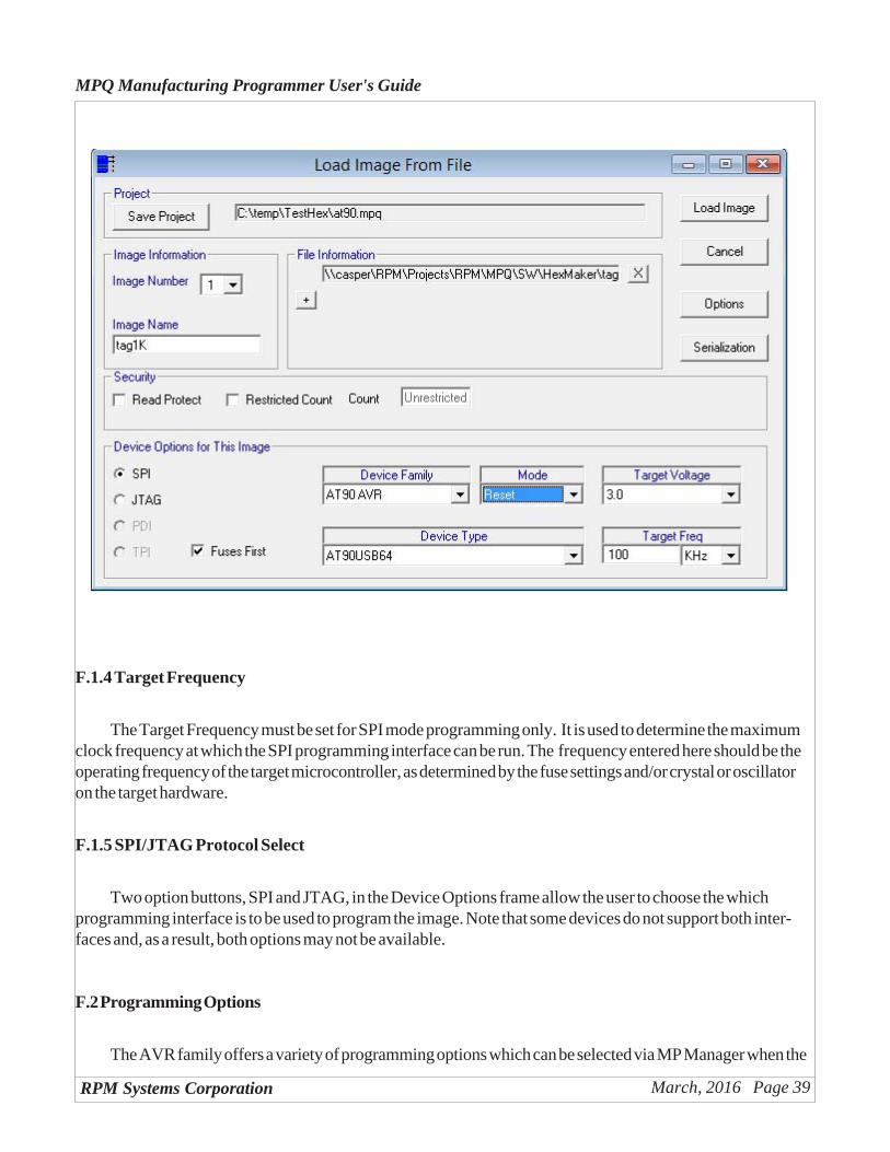
F.1.4 Target Frequency
The Target Frequency must be set for SPI mode programming only. It is used to determine the maximumclock frequency at which the SPI programming interface can be run. The frequency entered here should be theoperating frequency of the target microcontroller, as determined by the fuse settings and/or crystal or oscillatoron the target hardware.
F.1.5 SPI/JTAG Protocol Select
Two option buttons, SPI and JTAG, in the Device Options frame allow the user to choose the whichprogramming interface is to be used to program the image. Note that some devices do not support both inter-faces and, as a result, both options may not be available.
F.2 Programming Options
The AVR family offers a variety of programming options which can be selected via MP Manager when the
RPM Systems Corporation March, 2016 Page 40
MPQ Manufacturing Programmer User's Guide
image is loaded into the programmer. From the "Load Image from File" window, click the "Options" button toopen the AVR Options window. The options include fuse settings, optional EEPROM programming andoptional OSCCAL value selection. The desired programming options must be selected prior to clicking the"Load Image" button.
The available programming options are device dependent, so be certain to select the target device from the"Device Type" dropdown list before opening the Options window. Make the desired changes in the Optionswindow, as described below, then click Accept to return to the main Load Image window. You may open theOptions window again, to make additional changes or verify values, as many times as necessary before clickingLoad Image.
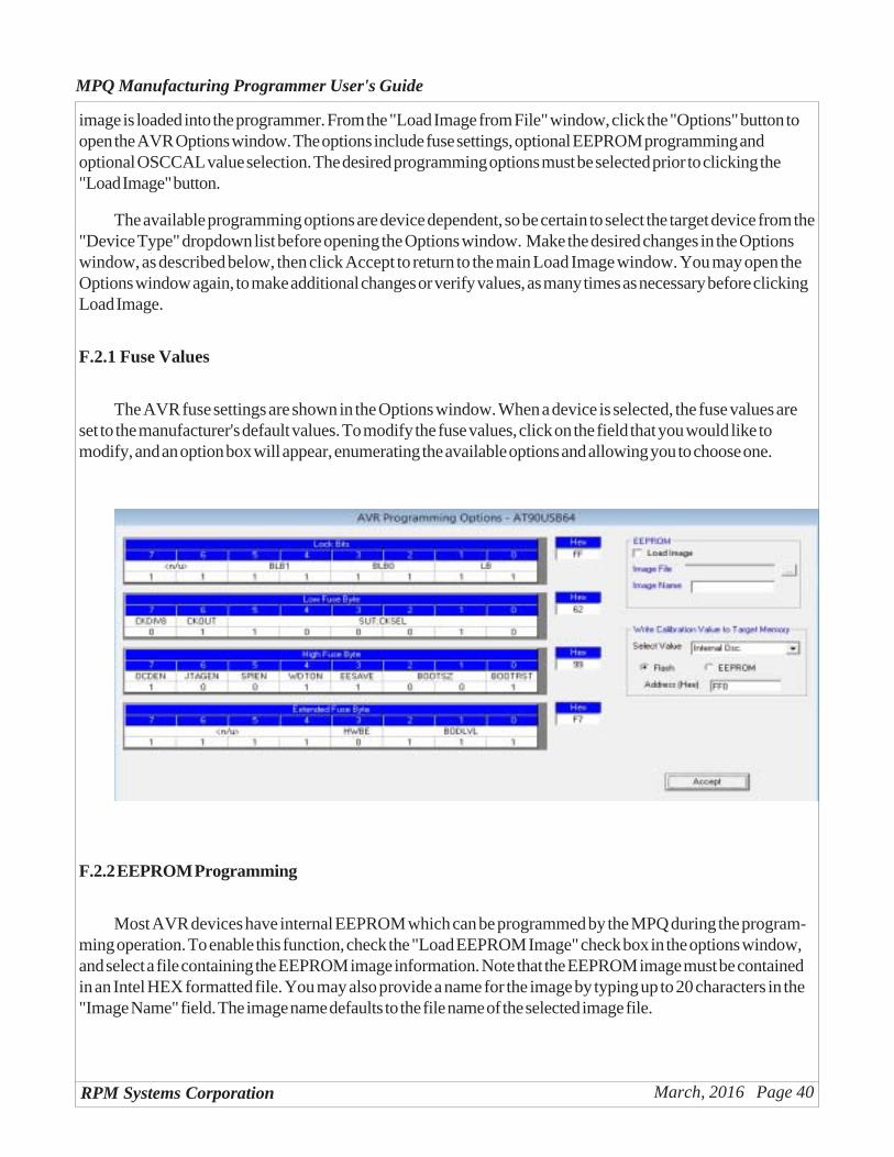
F.2.1 Fuse Values
The AVR fuse settings are shown in the Options window. When a device is selected, the fuse values areset to the manufacturer's default values. To modify the fuse values, click on the field that you would like tomodify, and an option box will appear, enumerating the available options and allowing you to choose one.
F.2.2 EEPROM Programming
Most AVR devices have internal EEPROM which can be programmed by the MPQ during the program-ming operation. To enable this function, check the "Load EEPROM Image" check box in the options window,and select a file containing the EEPROM image information. Note that the EEPROM image must be containedin an Intel HEX formatted file. You may also provide a name for the image by typing up to 20 characters in the"Image Name" field. The image name defaults to the file name of the selected image file.
RPM Systems Corporation March, 2016 Page 41
MPQ Manufacturing Programmer User's GuideF.2.3 OSCCAL Programming
Different members of the AVR families provide a selection of internal oscillators which may be selected asthe system clock. Each part provides one or more factory-provided calibration values which, when loaded intothe OSCCAL register in the microcontroller, tune the internal oscillator to provide a more accurate frequencysetting. The calibration value, or one of the calibration values in the case where multiple values are provided, isautomatically loaded into the part's OSCCAL register upon reset. However, the value(s) cannot be readdirectly by microcontroller firmware. For those applications which require access to the calibration value, MPQwill write the value to a predetermined location in Flash or EEPROM when the part is programed. TO use thisfeature, select the desired calibration value from the dropdown box in the Options window, select EEPROM orFlash and provide an address for the value to be programmed. If this feature is not desired, select "None" fromthe dropdown box in this option frame. This is the default condition.
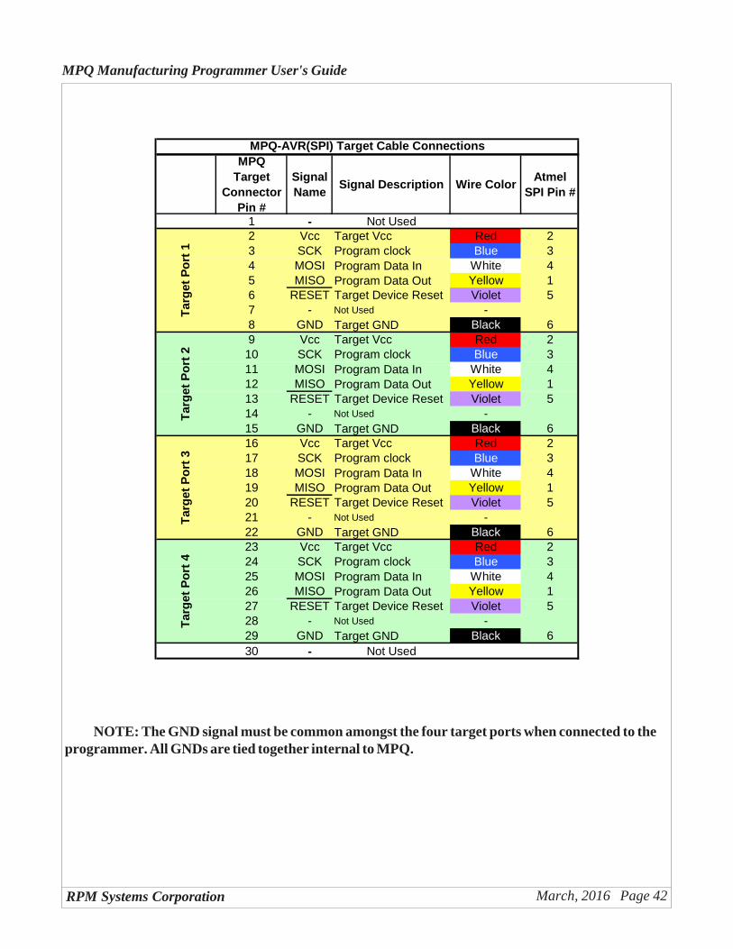
F.3 - Target Cable Connections
The MPQ-AVR is shipped with two Target Cable assemblies - one for SPI and one for JTAG program-ming. The connector pinouts correspond to the standard 0.1" x 0.1" spaced 6-pin (SPI) and 10-pin (JTAG)programming connectors specified by Atmel for SPI and JTAG programming. The following tables show thepin assignments for the various connectors. Note that one Target Cable assembly provides four sets of targetprogramming signals.
RPM Systems Corporation March, 2016 Page 42
MPQ Manufacturing Programmer User's Guide
MPQ Target
Connector Pin #
Signal Name
Signal Description Wire ColorAtmel
SPI Pin #
1 - Not Used2 Vcc Target Vcc Red 23 SCK Program clock Blue 34 MOSI Program Data In White 45 MISO Program Data Out Yellow 16 RESET Target Device Reset Violet 57 - Not Used -8 GND Target GND Black 69 Vcc Target Vcc Red 210 SCK Program clock Blue 311 MOSI Program Data In White 412 MISO Program Data Out Yellow 113 RESET Target Device Reset Violet 514 - Not Used -15 GND Target GND Black 616 Vcc Target Vcc Red 217 SCK Program clock Blue 318 MOSI Program Data In White 419 MISO Program Data Out Yellow 120 RESET Target Device Reset Violet 521 - Not Used -22 GND Target GND Black 623 Vcc Target Vcc Red 224 SCK Program clock Blue 325 MOSI Program Data In White 426 MISO Program Data Out Yellow 127 RESET Target Device Reset Violet 528 - Not Used -29 GND Target GND Black 630 - Not Used
MPQ-AVR(SPI) Target Cable Connections
Tar
get
Po
rt 4
Tar
get
Po
rt 1
Tar
get
Po
rt 2
Tar
get
Po
rt 3
NOTE: The GND signal must be common amongst the four target ports when connected to theprogrammer. All GNDs are tied together internal to MPQ.
RPM Systems Corporation March, 2016 Page 43
MPQ Manufacturing Programmer User's Guide
MPQ Target
Connector Pin #
Signal Name
Signal Description Wire ColorAtmel
JTAG Pin #
1 - Not Used2 Vcc Target Vcc Red 43 TCK Program clock Blue 14 TDI Program Data In White 95 TDO Program Data Out Yellow 36 RESET Target Device Reset Violet 67 TMS Program Mode Select Green 58 GND Target GND Black 29 Vcc Target Vcc Red 410 TCK Program clock Blue 111 TDI Program Data In White 912 TDO Program Data Out Yellow 313 RESET Target Device Reset Violet 614 TMS Program Mode Select Green 515 GND Target GND Black 216 Vcc Target Vcc Red 417 TCK Program clock Blue 118 TDI Program Data In White 919 TDO Program Data Out Yellow 320 RESET Target Device Reset Violet 621 TMS Program Mode Select Green 522 GND Target GND Black 223 Vcc Target Vcc Red 424 TCK Program clock Blue 125 TDI Program Data In White 926 TDO Program Data Out Yellow 327 RESET Target Device Reset Violet 628 TMS Program Mode Select Green 529 GND Target GND Black 230 - Not Used
MPQ-AVR(JTAG) Target Cable Connections
Tar
get
Po
rt 4
Tar
get
Po
rt 1
Tar
get
Po
rt 2
Tar
get
Po
rt 3
NOTE: The GND signal must be common amongst the four target ports when connected to theprogrammer. All GNDs are tied together internal to MPQ.
RPM Systems Corporation March, 2016 Page 44
MPQ Manufacturing Programmer User's Guide
Appendix G - Atmel AVR32
This appendix provides details of connection and operation of the MPQ programmer for Atmel AVR32microcontrollers.
G.1 Device Options
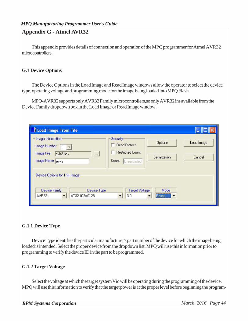
The Device Options in the Load Image and Read Image windows allow the operator to select the devicetype, operating voltage and programming mode for the image being loaded into MPQ Flash.
MPQ-AVR32 supports only AVR32 Family microcontrollers,so only AVR32 ins available from theDevice Family dropdown box in the Load Image or Read Image window.
G.1.1 Device Type
Device Type identifies the particular manufacturer's part number of the device for which the image beingloaded is intended. Select the proper device from the dropdown list. MPQ will use this information prior toprogramming to verify the device ID in the part to be programmed.
G.1.2 Target Voltage
Select the voltage at which the target system Vio will be operating during the programming of the device.MPQ will use this information to verify that the target power is at the proper level before beginning the program-
RPM Systems Corporation March, 2016 Page 45
MPQ Manufacturing Programmer User's Guide
ming operation. The selection of target voltages available in the dropdown list will depend upon the particulardevice selected in "Device Type", so make the device type selection first.
G.1.3 Mode
There are two Mode selections available for AVR32, "Reset" and "Run". The Mode selection determineswhether the target system will be held in reset at the completion of a program cycle ("Reset"), or be reset andthen permitted to begin code execution ("Run").
G.2 Programming Options
The AVR32 family offers a variety of programming options which can be selected via MP Manager whenthe image is loaded into the programmer. From the "Load Image from File" window, click the "Options" buttonto open the AVR Options window. The options include fuse settings, optional User Memory programming andSecurity Fuse programming. The desired programming options must be selected prior to clicking the "LoadImage" button.
The available programming options are device dependent, so be certain to select the target device from the"Device Type" dropdown list before opening the Options window. Make the desired changes in the Optionswindow, as described below, then click Accept to return to the main Load Image window. You may open theOptions window again, to make additional changes or verify values, as many times as necessary before clickingLoad Image.
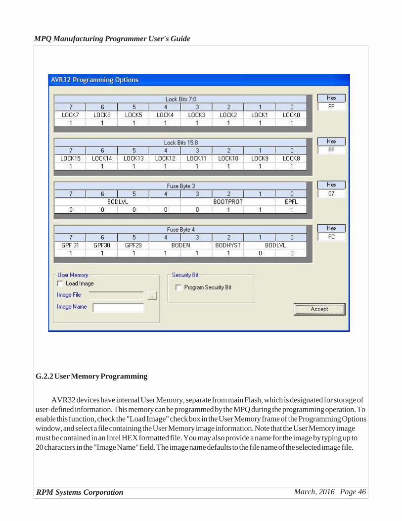
G.2.1 Fuse Values
The AVR32 fuse settings are shown in the Options window. When a device is selected, the fuse values areset to the manufacturer's default values. To modify the fuse values, click on the field that you would like tomodify, and an option box will appear, enumerating the available options and allowing you to choose one.
RPM Systems Corporation March, 2016 Page 46
MPQ Manufacturing Programmer User's Guide
G.2.2 User Memory Programming
AVR32 devices have internal User Memory, separate from main Flash, which is designated for storage ofuser-defined information. This memory can be programmed by the MPQ during the programming operation. Toenable this function, check the "Load Image" check box in the User Memory frame of the Programming Optionswindow, and select a file containing the User Memory image information. Note that the User Memory imagemust be contained in an Intel HEX formatted file. You may also provide a name for the image by typing up to20 characters in the "Image Name" field. The image name defaults to the file name of the selected image file.
RPM Systems Corporation March, 2016 Page 47
MPQ Manufacturing Programmer User's Guide
G.2.3 Security Bit Programming
In addition to the LOCK bits in the fuse bytes, the AVR32 provides a Security bit, which prevents allfurther JTAG access to flash memory and fuse bits. The MPQ allows this bit to be programmed at the comple-tion of the memory programming cycle. To select this features, check the "Program Security Bit' box in the"Security Bit" frame of the AVR Programming Options window. Note that, once the security bit has beenprogrammed, future verify operations performed on the device will failm as flash is no longer readable from theJTAG port. The Secuirty Bit can only be cleared by a chip erase operation.
G.3 - Target Cable Connections
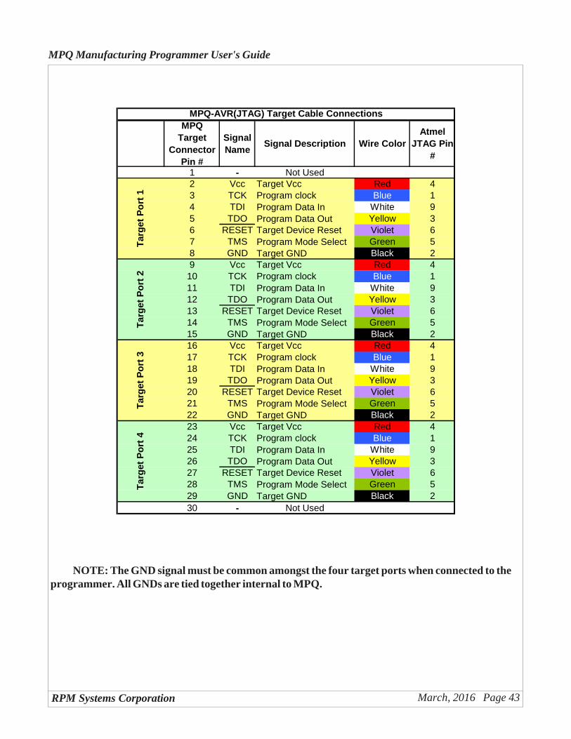
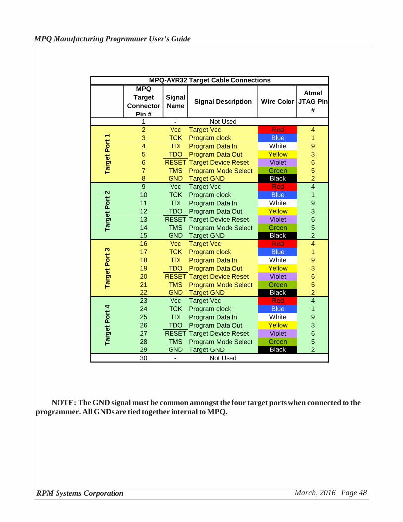
The MPQ-AVR32 is shipped with one JTAG programming cable. The connector pinouts correspond tothe standard 0.1" x 0.1" spaced 10-pin programming connectors specified by Atmel JTAG programming. Thefollowing tables shows the pin assignments for the various connectors. Note that one Target Cable assemblyprovides four sets of target programming signals.
RPM Systems Corporation March, 2016 Page 48
MPQ Manufacturing Programmer User's Guide
MPQ Target
Connector Pin #
Signal Name
Signal Description Wire ColorAtmel
JTAG Pin #
1 - Not Used2 Vcc Target Vcc Red 43 TCK Program clock Blue 14 TDI Program Data In White 95 TDO Program Data Out Yellow 36 RESET Target Device Reset Violet 67 TMS Program Mode Select Green 58 GND Target GND Black 29 Vcc Target Vcc Red 410 TCK Program clock Blue 111 TDI Program Data In White 912 TDO Program Data Out Yellow 313 RESET Target Device Reset Violet 614 TMS Program Mode Select Green 515 GND Target GND Black 216 Vcc Target Vcc Red 417 TCK Program clock Blue 118 TDI Program Data In White 919 TDO Program Data Out Yellow 320 RESET Target Device Reset Violet 621 TMS Program Mode Select Green 522 GND Target GND Black 223 Vcc Target Vcc Red 424 TCK Program clock Blue 125 TDI Program Data In White 926 TDO Program Data Out Yellow 327 RESET Target Device Reset Violet 628 TMS Program Mode Select Green 529 GND Target GND Black 230 - Not Used
MPQ-AVR32 Target Cable Connections
Tar
get
Po
rt 4
Tar
get
Po
rt 1
Tar
get
Po
rt 2
Tar
get
Po
rt 3
NOTE: The GND signal must be common amongst the four target ports when connected to theprogrammer. All GNDs are tied together internal to MPQ.