Embed Size (px)
Citation preview

MPR121 Hookup Guide a learn.sparkfun.com tutorial
Available online at: http://sfe.io/t137
Contents
MPR121 OverviewCapacitive Touch Sensor Breakout BoardCommunicating with the Breakout BoardTouch ShieldCommunicating with the ShieldCapacitive Touch KeypadCommunicating with the KeypadResources and Going Further
MPR121 Overview
If you are interested in adding the ‘magic’ of touch to control your electronics project, a capacitive touch sensor might be theway to go. This hookup guide will show you how to use the MPR121QR2 sensor.
The MPR121QR2 is a capacitive touch sensor controller that makes it very easy to integrate capacitive touch sensing into yourproject. It communicates via I2C, and works by measuring the capacitance of twelve electrode points. When an object comesclose to the electrode connector, the measured capacitance changes. This signals the MPR121 that something has touched a‘button’. The IC is also capable of driving LEDs or basic GPIO functionality on electrode pins 4 through 11, giving you a lot offreedom for setting up your project. The sensor works from 1.6V to 3.3V. The sensor isn’t very current-hungry, drawing onlyaround 29 µA when sampling every 16 milliseconds.
Materials
To work through this tutorial, you are going to need one of the three versions of the MPR121 sensor:
MPR121 Capacitive Touch Sensor Breakout BoardTouch ShieldMPR121 Capacitive Touch Keypad
You will also want a soldering iron, some hookup wires and a microcontroller capable of I2C communication. For our examples,we will be using an Arduino Uno. You will also need some kind of material to act as a capacitive sensing surface (also known asan electrode, which is not to be confused with the character Electrode). Generally, aluminum foil works well. However, you couldalso use coins, conductive paint, or copper tape.
Page 1 of 16

Suggested Reading
The MPR121 is very easy to get started using, especially with the example code. However, if you haven’t worked with Arduinopreviously or aren’t familiar with I2C communication, you should check out the tutorials below.
What is an ArduinoI2C CommunicationHow to Use a BreadboardHow to Solder
Capacitive Touch Sensor Breakout Board
The SparkFun Capacitive Touch Sensor Breakout Board is the most versatile option of the three MPR121 products. You canwire it up to any kind of electrode you want, and, as it is a simple breakout board, does not have a particular microcontrollerfootprint it favors.
SparkFun Capacitive Touch Sensor Breakout - MPR121
SEN-096954 RetiredFavorited Favorite 14Wish List
The breakout board has 4 pins that need to be connected to your microcontroller at a minimum to get communication going: thepower lines and the I2C lines. However, for our example, we are going to be also connecting the IRQ pin to more easily detect achange on one of the electrodes.
Connections
MPR121 Breakout → Arduino Uno
3.3V → 3.3VSCL → A5
Page 2 of 16

SDA → A4GND → GNDIRQ → D2
You will also want to connect the Electrode/LED pins to your electrode material you selected previously. You will want to makesure you have a good, solid connection between your material and your board, so make sure you thoroughly solder yourconnections.
Check out the Fritzing diagram below for how your connections should look. The yellow squares represent whatever materialyou decide to use for your electrodes.
Communicating with the Breakout Board
To communicate with your breakout board, you will need the Arduino sketch available as a zip file here. Alternatively, you canalso find the most up-to-date firmware for working with the breakout board available on GitHub. Let’s take a look and seeexactly what the code is doing.
language:c #include "mpr121.h" #include <Wire.h>
int irqpin = 2; // Digital 2 boolean touchStates[12]; //to keep track of the previous touch states
In this first section of the code, the MPR121 library and the Wire library are initialized. The Wire library makes I2Ccommunication easy to use on the Arduino. The sketch also defines digital pin 2 as the IRQ pin connection, and creates 12instances of the boolean variable touchStates.
For the second section of the code, we define the irqpin as an INPUT, telling the Arduino to monitor the digital signal coming inover that pin. Serial communication is also started at 9600 bps, s well as the Wire and mpr121 libraries.
language:c void setup(){ pinMode(irqpin, INPUT); digitalWrite(irqpin, HIGH); //enable pullup resistor
Serial.begin(9600); Wire.begin();
mpr121_setup(); }
The main loop of the code is incredibly simple, as it only calls a single function.
language:c void loop(){ readTouchInputs(); }
Page 3 of 16

The function is actually described in the next section of the code. The Arduino requests the electrode states from the sensor inthe first section, and the least significant bits and most significant bits are defined for the sensor.
language:cvoid readTouchInputs(){ if(!checkInterrupt()){
//read the touch state from the MPR121 Wire.requestFrom(0x5A,2);
byte LSB = Wire.read(); byte MSB = Wire.read();
uint16_t touched = ((MSB << 8) | LSB); //16bits that make up the touch states
for (int i=0; i < 12; i++){ // Check what electrodes were pressed if(touched & (1<<i)){
if(touchStates[i] == 0){ //pin i was just touched Serial.print("pin "); Serial.print(i); Serial.println(" was just touched");
}else if(touchStates[i] == 1){ //pin i is still being touched }
touchStates[i] = 1; }else{ if(touchStates[i] == 1){ Serial.print("pin "); Serial.print(i); Serial.println(" is no longer being touched");
//pin i is no longer being touched }
touchStates[i] = 0; }
}
}}
The Arduino scans each electrode and prints out a message over serial if an electrode is triggered as being touched. TheArduino will then print out a message as soon as the electrode is no longer being touched.
The last major section of the code defines the threshold values for each electrode. Each electrode must have a touch thresholdand a release threshold for the Arduino to compare the current state of the electrode.
language:cvoid mpr121_setup(void){
set_register(0x5A, ELE_CFG, 0x00);
// Section A - Controls filtering when data is > baseline. set_register(0x5A, MHD_R, 0x01); set_register(0x5A, NHD_R, 0x01); set_register(0x5A, NCL_R, 0x00); set_register(0x5A, FDL_R, 0x00);
// Section B - Controls filtering when data is < baseline. set_register(0x5A, MHD_F, 0x01); set_register(0x5A, NHD_F, 0x01); set_register(0x5A, NCL_F, 0xFF); set_register(0x5A, FDL_F, 0x02);
Page 4 of 16

// Section C - Sets touch and release thresholds for each electrode set_register(0x5A, ELE0_T, TOU_THRESH); set_register(0x5A, ELE0_R, REL_THRESH);
set_register(0x5A, ELE1_T, TOU_THRESH); set_register(0x5A, ELE1_R, REL_THRESH);
set_register(0x5A, ELE2_T, TOU_THRESH); set_register(0x5A, ELE2_R, REL_THRESH);
set_register(0x5A, ELE3_T, TOU_THRESH); set_register(0x5A, ELE3_R, REL_THRESH);
set_register(0x5A, ELE4_T, TOU_THRESH); set_register(0x5A, ELE4_R, REL_THRESH);
set_register(0x5A, ELE5_T, TOU_THRESH); set_register(0x5A, ELE5_R, REL_THRESH);
set_register(0x5A, ELE6_T, TOU_THRESH); set_register(0x5A, ELE6_R, REL_THRESH);
set_register(0x5A, ELE7_T, TOU_THRESH); set_register(0x5A, ELE7_R, REL_THRESH);
set_register(0x5A, ELE8_T, TOU_THRESH); set_register(0x5A, ELE8_R, REL_THRESH);
set_register(0x5A, ELE9_T, TOU_THRESH); set_register(0x5A, ELE9_R, REL_THRESH);
set_register(0x5A, ELE10_T, TOU_THRESH); set_register(0x5A, ELE10_R, REL_THRESH);
set_register(0x5A, ELE11_T, TOU_THRESH); set_register(0x5A, ELE11_R, REL_THRESH);
// Section D // Set the Filter Configuration // Set ESI2 set_register(0x5A, FIL_CFG, 0x04);
// Section E // Electrode Configuration // Set ELE_CFG to 0x00 to return to standby mode set_register(0x5A, ELE_CFG, 0x0C); // Enables all 12 Electrodes
// Section F // Enable Auto Config and auto Reconfig /*set_register(0x5A, ATO_CFG0, 0x0B); set_register(0x5A, ATO_CFGU, 0xC9); // USL = (Vdd-0.7)/vdd*256 = 0xC9 @3.3V set_register(0x5A, ATO_CFGL, 0x82); // LSL = 0.65*USL = 0x82 @3.3V set_register(0x5A, ATO_CFGT, 0xB5);*/ // Target = 0.9*USL = 0xB5 @3.3V
set_register(0x5A, ELE_CFG, 0x0C);
}
It looks like a lot of code, but it simply repeating the procedure of setting the threshold values for each electrode pin.
The last two functions in the example sketch simply check the status of the irqpin to determine if the IC is signaling that anelectrode has been touched. The very last function set_register simply runs the Arduino through the standard steps in the Wirelibrary to write the registers to the IC.
language:cboolean checkInterrupt(void){ return digitalRead(irqpin);}
void set_register(int address, unsigned char r, unsigned char v){
Page 5 of 16

Wire.beginTransmission(address); Wire.write(r); Wire.write(v); Wire.endTransmission();}
Now that you have a basic understanding of the code, let’s start reading the data. Open up the sketch from the file youdownloaded earlier, and upload it to your Arduino. Once it is uploaded, open the Serial monitor in the Arduino IDE. You shouldstart seeing the Arduino print out sentences if you press any electrodes or release any electrodes.
Touch Shield
The SparkFun Touch Shield is an Arduino R3 compatible shield that enables capacitive touch capabilities for your project usingthe MPR121 IC. The shield itself has 9 touch pads on it (conveniently numbered 1-9 in a 3x3 grid), and has headers for 3additional electrode connections.
SparkFun Touch Shield
DEV-12013RetiredFavorited Favorite 15Wish List
The shield connects directly to the 3.3V pin on the Arduino. There is no on-board voltage regulation on the VCC line, so keepthat in mind if you intend to use this with a 5V Arduino Pro board. However, there is an onboard logic level converter to stepdown 5V levels to the 3.3V for the sensor’s I2C lines.
This shield is designed to interface with an Arduino Uno R3. You can use other microcontrollers as well with the same footprint,such as the Arduino Mega. You will need access to the I2C pins, SDA and SCL. Other than that, you will need access to the3.3V and GND pins and to digital pin 2. This connects to the INT pin on the MPR121 sensor.
We generally use stackable headers for attaching shields to Arduino boards, but you can use standard male headers if youprefer. The R3 Stackable Header Kit is the easiest option to use if you are planning on stackable headers. For detailedinstructions on how to assemble your shield, have a look at our Shield Tutorial.
Page 6 of 16

The shield also has 3 pins labeled ELE9, ELE10, and ELE11. These correspond to electrodes 9,10, and 11 on the MPR121chip. You can solder additional buttons or connections on to these pins at this time if you want more than the 9 buttons alreadyavailable on the shield. However, you don’t have to do this to get the shield to function. It’s up to you!
Check out the Fritzing diagram below to see how your shield should look if you have added buttons on to your shield on pinsELE9, ELE10, and ELE11.
Note: The yellow squares represent whatever material you’ve chosen to use as your electrode.
Once you’ve got your shield all hooked up, let’s start pulling data from the shield!
Communicating with the Shield
Once you’ve got your shield assembled, it’s time to start talking to it! You can download the example code here, or find the mostup-to-date version in the GitHub repository.
Open up the Touch_Sensor_Shield_Example.ino file. The other files set the register definitions for the MPR121 chip, so youshouldn’t need to mess with these at all.
language:c // Match key inputs with electrode numbers #define ONE 8 #define TWO 5 #define THREE 2 #define FOUR 7 #define FIVE 4 #define SIX 1 #define SEVEN 6 #define EIGHT 3 #define NINE 0
Page 7 of 16
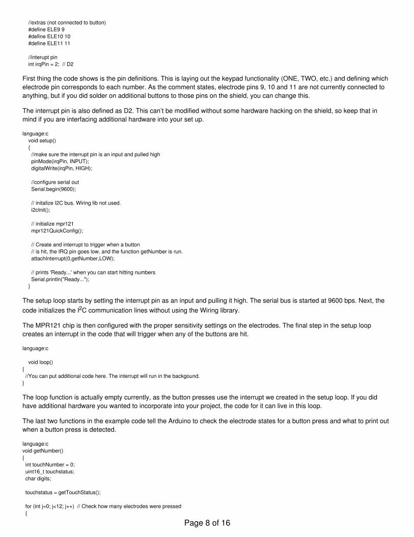
//extras (not connected to button) #define ELE9 9 #define ELE10 10 #define ELE11 11
//interupt pin int irqPin = 2; // D2
First thing the code shows is the pin definitions. This is laying out the keypad functionality (ONE, TWO, etc.) and defining whichelectrode pin corresponds to each number. As the comment states, electrode pins 9, 10 and 11 are not currently connected toanything, but if you did solder on additional buttons to those pins on the shield, you can change this.
The interrupt pin is also defined as D2. This can’t be modified without some hardware hacking on the shield, so keep that inmind if you are interfacing additional hardware into your set up.
language:c void setup() { //make sure the interrupt pin is an input and pulled high pinMode(irqPin, INPUT); digitalWrite(irqPin, HIGH);
//configure serial out Serial.begin(9600);
// initalize I2C bus. Wiring lib not used. i2cInit();
// initialize mpr121 mpr121QuickConfig();
// Create and interrupt to trigger when a button // is hit, the IRQ pin goes low, and the function getNumber is run. attachInterrupt(0,getNumber,LOW);
// prints 'Ready...' when you can start hitting numbers Serial.println("Ready..."); }
The setup loop starts by setting the interrupt pin as an input and pulling it high. The serial bus is started at 9600 bps. Next, thecode initializes the I2C communication lines without using the Wiring library.
The MPR121 chip is then configured with the proper sensitivity settings on the electrodes. The final step in the setup loopcreates an interrupt in the code that will trigger when any of the buttons are hit.
language:c
void loop(){ //You can put additional code here. The interrupt will run in the backgound. }
The loop function is actually empty currently, as the button presses use the interrupt we created in the setup loop. If you didhave additional hardware you wanted to incorporate into your project, the code for it can live in this loop.
The last two functions in the example code tell the Arduino to check the electrode states for a button press and what to print outwhen a button press is detected.
language:cvoid getNumber(){ int touchNumber = 0; uint16_t touchstatus; char digits;
touchstatus = getTouchStatus();
for (int j=0; j<12; j++) // Check how many electrodes were pressed {
Page 8 of 16

if ((touchstatus & (1<<j))) touchNumber++; }
if (touchNumber == 1) { if (touchstatus & (1<<SEVEN)) { digits = '7'; } else if (touchstatus & (1<<FOUR)) { digits = '4'; } else if (touchstatus & (1<<ONE)) { digits = '1'; } else if (touchstatus & (1<<EIGHT)) { digits = '8'; } else if (touchstatus & (1<<FIVE)) { digits = '5'; } else if (touchstatus & (1<<TWO)) { digits = '2'; } else if (touchstatus & (1<<NINE)) { digits = '9'; } else if (touchstatus & (1<<SIX)) { digits = '6'; } else if (touchstatus & (1<<THREE)) { digits = '3'; } Serial.println(digits); } //do nothing if more than one button is pressed, or if all are released else if (touchNumber == 0) ; else ;}
The function getTouchStatus() actually returns at 16-bit value which gives the status of each button. The status of 1 indicates thatan electrode is being activated.
language: c int getTouchStatus(){ int touch;
touch = mpr121Read(0x01) << 8; touch |= mpr121Read(0x00);
return touch;}
Now that you have basic communication up and running with your shield, you can start integrating this into projects. If youhaven’t yet connected anything to electrodes 9, 10 and 11, consider adding in additional buttons here. You will also need toupdate the code. You’ll want to add the following block of code into the example sketch right before Serial.println(digits);. You canchange the digits values to have the buttons output different values instead of “A”, “B”, or “C”.
Page 9 of 16

language:c else if (touchstatus & (1 << ELE9)){ digits = 'A';}else if (touchstatus & (1 << ELE10)){ digits = 'B';}else if (touchstatus & (1 << ELE11)){ digits = 'C';}
Capacitive Touch Keypad
The SparkFun Capacitive Touch Keypad is very similar to the MPR121 breakout board, but instead of having to attach yourown electrodes, this board comes with a 12-pin keypad built-in.
SparkFun Capacitive Touch Keypad - MPR121
SEN-120172 RetiredFavorited Favorite 10Wish List
The keypad has 5 lines that need to be connected to your microcontroller, including the power lines, the IRQ line and the I2Clines.
Connections
MPR121 Keypad → Arduino Uno
3.3V → 3.3VSCL → A5SDA → A4
Page 10 of 16

GND → GNDIRQ → D2
Check out the Fritzing diagram below to verify your connections.
This diagram shows the bottom side of the keypad, in order to show you the location of the I2C address jumper. In this diagram,the jumper is set to 0, but if you need to have 2 keypads on the same I2C bus, you can change one of them to be set to 1.
Now that you’ve got your keypad hooked up properly, let’s get communicating with it!
Communicating with the Keypad
In order to communicate with your keypad, you’ll want to download the example sketch available here. Alternatively, you cancheck for the most up-to-date firmware available in the GitHub repository.
This sketch is designed to allow the keypad to function as a phone keypad. Check out the pin mapping below to see how thenumbered pads will print over the Serial terminal.
Actual Keypad → Phone Keypad Printout
3 → 17 → 211 → 32 → 46 → 510 → 61 → 75 → 89 → 90 → *4 → 08 → #
This is defined in the first section of the code, shown below. The I2C address is also defined, along with setting digital pin 2 tobe assigned as the IRQ pin connection point.
language:c#include "mpr121.h"#include "i2c.h"
#define MPR121_R 0xB5 // ADD pin is grounded#define MPR121_W 0xB4 // So address is 0x5A
#define PHONE_DIGITS 10 // 10 digits in a phone number
// Match key inputs with electrode numbers#define STAR 0#define SEVEN 1
Page 11 of 16

#define FOUR 2#define ONE 3#define ZERO 4#define EIGHT 5#define FIVE 6#define TWO 7#define POUND 8#define NINE 9#define SIX 10#define THREE 11
int irqpin = 2; // D2
uint16_t touchstatus;char phoneNumber[PHONE_DIGITS];
The second section of the code is the basic initialization of the serial communication port at 9600 bps, as well as setting the IRQpin as an input on the Arduino. It also starts the configuraton of the MPR121 IC.
language:cvoid setup(){ pinMode(irqpin, INPUT); digitalWrite(irqpin, HIGH);
Serial.begin(9600); DDRC |= 0b00010011; PORTC = 0b00110000; // Pull-ups on I2C Bus i2cInit();
delay(100); mpr121QuickConfig();}
The main loop in the code simply scans the MPR121 electrodes and looks for a phone number to be entered on the keypad.This is the function getPhoneNumber(). The code then prints out the phone number dialed over the serial monitor.
language:cvoid loop(){ getPhoneNumber();
Serial.print("\nDialing... "); for (int i=0; i<PHONE_DIGITS; i++) Serial.print(phoneNumber[i]);
while(1) ;}
As you can see in the function loop for getPhoneNumber(), the Arduino checks the touchstatus register for each electrode and printsout the assigned value for any electrodes that are registering a touch. It also includes an error if multiple buttons are pressedsimultaneously, printing over the serial monitor to tell the user to touch only one button.
language:cvoid getPhoneNumber(){ int i = 0; int touchNumber;
Serial.println("Please Enter a phone number...");
while(i<PHONE_DIGITS) { while(checkInterrupt()) ; touchNumber = 0;
touchstatus = mpr121Read(0x01) << 8; touchstatus |= mpr121Read(0x00);
Page 12 of 16

for (int j=0; j<12; j++) // Check how many electrodes were pressed { if ((touchstatus & (1<<j))) touchNumber++; }
if (touchNumber == 1) { if (touchstatus & (1<<STAR)) phoneNumber[i] = '*'; else if (touchstatus & (1<<SEVEN)) phoneNumber[i] = '7'; else if (touchstatus & (1<<FOUR)) phoneNumber[i] = '4'; else if (touchstatus & (1<<ONE)) phoneNumber[i] = '1'; else if (touchstatus & (1<<ZERO)) phoneNumber[i] = '0'; else if (touchstatus & (1<<EIGHT)) phoneNumber[i] = '8'; else if (touchstatus & (1<<FIVE)) phoneNumber[i] = '5'; else if (touchstatus & (1<<TWO)) phoneNumber[i] = '2'; else if (touchstatus & (1<<POUND)) phoneNumber[i] = '#'; else if (touchstatus & (1<<NINE)) phoneNumber[i] = '9'; else if (touchstatus & (1<<SIX)) phoneNumber[i] = '6'; else if (touchstatus & (1<<THREE)) phoneNumber[i] = '3';
Serial.print(phoneNumber[i]); i++; } else if (touchNumber == 0) ; else Serial.println("Only touch ONE button!"); }}
The next section of the code simply steps through the I2C communication to read data from the MPR121 IC.
language:cbyte mpr121Read(uint8_t address){ byte data;
i2cSendStart(); i2cWaitForComplete();
i2cSendByte(MPR121_W); // write 0xB4 i2cWaitForComplete();
i2cSendByte(address); // write register address i2cWaitForComplete();
i2cSendStart();
i2cSendByte(MPR121_R); // write 0xB5 i2cWaitForComplete(); i2cReceiveByte(TRUE); i2cWaitForComplete();
data = i2cGetReceivedByte(); // Get MSB result i2cWaitForComplete(); i2cSendStop();
Page 13 of 16

cbi(TWCR, TWEN); // Disable TWI sbi(TWCR, TWEN); // Enable TWI
return data;}
The function mpr121Write() is then defined, which again, steps through the I2C process of writing commands to the MPR121sensor.
language:cvoid mpr121Write(unsigned char address, unsigned char data){ i2cSendStart(); i2cWaitForComplete();
i2cSendByte(MPR121_W);// write 0xB4 i2cWaitForComplete();
i2cSendByte(address); // write register address i2cWaitForComplete();
i2cSendByte(data); i2cWaitForComplete();
i2cSendStop();}
The mpr121QuickConfig() function is then defined. In this function, all 12 of the electrodes are enabled, and the touch and releasethresholds for all of the sensors are set. The filtering registers are also configured.
language:cvoid mpr121QuickConfig(void){ // Section A // This group controls filtering when data is > baseline. mpr121Write(MHD_R, 0x01); mpr121Write(NHD_R, 0x01); mpr121Write(NCL_R, 0x00); mpr121Write(FDL_R, 0x00);
// Section B // This group controls filtering when data is < baseline. mpr121Write(MHD_F, 0x01); mpr121Write(NHD_F, 0x01); mpr121Write(NCL_F, 0xFF); mpr121Write(FDL_F, 0x02);
// Section C // This group sets touch and release thresholds for each electrode mpr121Write(ELE0_T, TOU_THRESH); mpr121Write(ELE0_R, REL_THRESH); mpr121Write(ELE1_T, TOU_THRESH); mpr121Write(ELE1_R, REL_THRESH); mpr121Write(ELE2_T, TOU_THRESH); mpr121Write(ELE2_R, REL_THRESH); mpr121Write(ELE3_T, TOU_THRESH); mpr121Write(ELE3_R, REL_THRESH); mpr121Write(ELE4_T, TOU_THRESH); mpr121Write(ELE4_R, REL_THRESH); mpr121Write(ELE5_T, TOU_THRESH); mpr121Write(ELE5_R, REL_THRESH); mpr121Write(ELE6_T, TOU_THRESH); mpr121Write(ELE6_R, REL_THRESH); mpr121Write(ELE7_T, TOU_THRESH); mpr121Write(ELE7_R, REL_THRESH); mpr121Write(ELE8_T, TOU_THRESH); mpr121Write(ELE8_R, REL_THRESH); mpr121Write(ELE9_T, TOU_THRESH); mpr121Write(ELE9_R, REL_THRESH); mpr121Write(ELE10_T, TOU_THRESH);
Page 14 of 16

mpr121Write(ELE10_R, REL_THRESH); mpr121Write(ELE11_T, TOU_THRESH); mpr121Write(ELE11_R, REL_THRESH);
// Section D // Set the Filter Configuration // Set ESI2 mpr121Write(FIL_CFG, 0x04);
// Section E // Electrode Configuration // Enable 6 Electrodes and set to run mode // Set ELE_CFG to 0x00 to return to standby mode mpr121Write(ELE_CFG, 0x0C); // Enables all 12 Electrodes //mpr121Write(ELE_CFG, 0x06); // Enable first 6 electrodes
// Section F // Enable Auto Config and auto Reconfig /*mpr121Write(ATO_CFG0, 0x0B); mpr121Write(ATO_CFGU, 0xC9); // USL = (Vdd-0.7)/vdd*256 = 0xC9 @3.3V mpr121Write(ATO_CFGL, 0x82); // LSL = 0.65*USL = 0x82 @3.3V mpr121Write(ATO_CFGT, 0xB5);*/ // Target = 0.9*USL = 0xB5 @3.3V}
The final section of the sketch simply reads the IRQ pin for an indication that an electrode has been pressed. It then returnseither a 1 or 0 as the value for checkInterrupt() variable.
language:cbyte checkInterrupt(void){ if(digitalRead(irqpin)) return 1;
return 0;}
Now that you know how the keypad works and communicates with the Arduino, you can start customizing your project andgoing further.
Resources and Going Further
Now that you’ve figured out how to use the various versions of the MPR121 IC, what kind of cool projects can you come upwith? If you have any questions still, check out the additional resources below, or feel free to leave a comment on the tutorial.
Resources
Example CodeMPR121 DatasheetMPR121 Breakout Board
Schematic (PDF)Eagle Files (ZIP)GitHub Repo
MPR121 Touch ShieldSchematic (PDF)Eagle Files (ZIP)GitHub Repo
MPR121 Touch PadSchematic (PDF)Eagle Files (ZIP)GitHub RepoSparkFun Simple Sketches - Capacitive Touch Keypad
Other I2C Projects and Products
All of these tutorials have I2C communication. They can also both be used in conjunction with this sensor to act as a display for
Page 15 of 16

the button triggers or to monitor the temperature as well.
OpenSegment Hook-Up GuideTMP006 Hook-Up Guide
learn.sparkfun.com | CC BY-SA 3.0 | SparkFun Electronics | Niwot, Colorado
Page 16 of 16