Embed Size (px)
Citation preview

GFS-1201
LDA-1201
WPI Recreation Center:
Track Alternative Design and Construction Management Software
A Major Qualifying Project
Submitted to the faculty of Worcester Polytechnic Institute
In partial fulfillment of the requirements for the
Degree of Bachelor of Science
Submitted By:
John Flynn
Kathryne Kulzer
Sean Minor
Suzanne Najem
Sponsoring Agency:
Gilbane Building Company
Submitted To:
Guillermo Salazar
Leonardo Albano
Date: March 2, 2012

WPI Recreation Center
i
Abstract
This project created an alternative support system for the suspended track in WPI’s new
Recreation Center. The development of the alternative design primarily addressed structural
integrity. A comparative analysis between the existing and alternative design was completed for
the design, cost, and schedule. Two Building Information Modeling software applications:
Autodesk Robot and Revit were used in supporting the study. Robot was explored as a new
program in structural analysis and Revit was used to create 4-D models of both designs.

WPI Recreation Center
ii
Capstone Design Statement
The capstone design requirements were met in this Major Qualifying Project through
studying the new Recreation Center at WPI. This project focused on creating an alternative
design for the suspended track system that is on the top floor of the new building and creating a
cost estimate and a schedule that would allow the group to complete a comparative analysis of
the existing and alternative designs. Finally, the schedule was integrated into BIM to create a 4-
D model. The alternative design used cantilever and simple beams to replace the suspension.
In order to meet the specified requirements for a capstone design experience, this project
addressed certain constraints set forth by the American Society of Civil Engineers. These
constraints include economic, health and safety, ethical, manufacturability, and social.
The economic constraint was addressed by looking at the effects of the alternative design
through a cost perspective. A cost estimate was created to compare the two designs. Also, the
project looked into construction contracts and studied the different types as well as the economic
benefits and differences of each type.
This project looked at the Health and Safety constraint through the alternative design.
The alternative design used the Massachusetts State Building Code: 7th
Edition as the building
code and the AISC Steel Construction Manual for design considerations and specifications.
These both are accepted standards that take health and safety into account.
Ethically, the alternative design was designed under the same ethical considerations taken
by Cannon Design. Cannon stated many of their assumptions on the cover sheet of the structural
package. All of these constraints were followed throughout the design process.
The next constraint studied was manufacturability. This project looked at how feasible it
would be to have an alternate design for the track system. Similar sized beams and columns were

WPI Recreation Center
iii
used to ensure that the design was of comparable constructability to the original design.
Construction of the alternative design does not require any extra major equipment, material, or
labor. This approach allowed for guaranteed manufacturability and constructability. The
constructability was also looked at through the schedule comparison and the creation of the 4-D
model.
All aspects of this MQP addressed the social constraint. The Recreation Center is a social
place that will be open for public use. The indoor track that is being installed is an important
aspect of the Recreation Center and will most likely be a widely used portion of the building. In
creating the alternative design, it had to be designed to meet all of the needs of the WPI
community in their wants for an indoor track. The project meetings gave insight into how
necessary the Recreation Center is and the social impact it will have on the campus. This project
also provided educational opportunities for the WPI community by allowing students of many
projects to be involved in the construction and development of the Recreation Center.

WPI Recreation Center
iv
Authorship Page
All aspects of this project were equally worked on by the four members of the team. The
following list outlines the areas of focus in the report for each member of the team.
John Flynn - Cost and Schedule Analyses of the Existing and Alterative design, 4-D Revit model
Kathryne Kulzer - Cost and Schedule Analyses of the Existing and Alterative design, 4-D Revit
model
Sean Minor - Cantilever Beam Approach, Corner Design of the Simple Beam Approach.
Suzanne Najem - Simple Beam Approach, Column Design, Robot.
The signatures below indicate acceptance of above.

WPI Recreation Center
v
Acknowledgements
Our Major Qualifying Project team would like to thank all of the individuals who
contributed to the creation of our Project. Out team would like to especially thank our advisors,
Professor Leonard Albano and Professor Guillermo Salazar for their help and guidance in
completing the project. Our team would also like to thank the Gilbane Building Company and
Cannon Design teams that were working on the WPI new Sports and Recreation Center project,
Mr. Neil Benner and Miss. Melissa Hinton from Gilbane Building Company, and Mr. Alfredo
DiMauro from WPI for providing us with valuable information; including access to their
structural drawings, and allowing our team members to attend the Owner’s meetings. Finally,
we would like to thank Ms. Dana Harmon from WPI for allowing us to conduct an interview
which gave us vital information that helped us towards in the completion of this project.

WPI Recreation Center
vi
Table of Contents
Abstract ................................................................................................................................ i
Capstone Design Statement ................................................................................................ ii
Authorship Page ................................................................................................................. iv
Acknowledgements ............................................................................................................. v
Table of Contents ............................................................................................................... vi
List of Figures .................................................................................................................... ix
List of Tables ..................................................................................................................... xi
List of Appendices ............................................................................................................ xii
Chapter 1 - Introduction ...................................................................................................... 1
Chapter 2 - Background ...................................................................................................... 4
2.1 Recreation Center................................................................................................ 4
2.2 Structural Evaluation .......................................................................................... 5
2.2.1 Suspended Track System ................................................................................ 6
2.2.2 Long-Span Roofing System .......................................................................... 10
2.2.3 Massachusetts Building Code ....................................................................... 11
2.3 Project Management ......................................................................................... 11
2.3.1 Schedule ........................................................................................................ 13
2.3.2 Cost ............................................................................................................... 20
2.4 Computer-Aided Engineering ........................................................................... 21
2.4.1 Robot Structural Analysis ............................................................................. 21
2.4.2 Building Information Modeling (BIM) ......................................................... 22
Chapter 3 - Benchmarking the Current Design................................................................. 29

WPI Recreation Center
vii
3.1 Revit Model Creation of Existing Design ......................................................... 29
3.2 Creation of Baseline Cost Estimate Based on Given Information .................... 29
3.3 Creation of Baseline Estimate Based on RS Means .......................................... 33
3.3.1 Estimate Process Based on Cost Data ........................................................... 34
3.4 Schedule Investigation of Current Design ........................................................ 37
3.5 Creation of 4-D BIM ......................................................................................... 41
Chapter 4 - Alternate Designs ........................................................................................... 46
4.1 Structural Evaluation ........................................................................................ 46
4.1.1 Existing Design Criteria & Adjustments ...................................................... 47
4.1.2 Alternative Design – Cantilever Approach ................................................... 50
4.1.3 Alternative Design – Simple Beam Approach .............................................. 52
4.1.4 Robot, Structural Analysis Program ............................................................. 55
4.1.5 Column Design ............................................................................................. 58
4.1.6 Revit Model ................................................................................................... 61
4.2 Cost Development for Alternative Design ........................................................ 62
4.3 Schedule Development for Alternative Design ................................................ 64
4.4 Creation of 4-D BIM for Alternate Design ....................................................... 68
Chapter 5 - Evaluation/Analysis of Designs ..................................................................... 72
5.1 Design Comparison ........................................................................................... 72
5.2 Cost Comparison ............................................................................................... 76
5.3 Schedule Comparison ....................................................................................... 77
5.3.1 Phase Comparison through Revit .................................................................. 81

WPI Recreation Center
viii
Chapter 6 – Conclusions & Recommendations ................................................................ 83
6.1 Recommendations Based on Comparisons ....................................................... 83
6.2 Utilization of Technology ................................................................................. 84
Chapter 7 - References ...................................................................................................... 86

WPI Recreation Center
ix
List of Figures
Figure 1: Construction Sections of the Recreation Center.................................................. 2
Figure 2: Current Suspended Track .................................................................................... 6
Figure 3: Cannon’s Structural Truss ................................................................................. 11
Figure 4: Primavera Schedule for Recreation Center (Gilbane, 2011) ............................. 16
Figure 5: November 2010 Schedule (Gilbane, 2011) ....................................................... 17
Figure 6: August 2011 Schedule (Gilbane, 2011) ............................................................ 18
Figure 7: Critical Path for the Pool (Gilbane, 2011) ......................................................... 19
Figure 8: BIM Contribution Breakdown (Partridge, 2011) .............................................. 23
Figure 9: BIM Site Plan (Knutson, 2011) ......................................................................... 25
Figure 10: Interface Detections (Hope, 2010) .................................................................. 26
Figure 11: Flowchart for Exporting Schedules ................................................................. 30
Figure 12: Flowchart for the Use of RS Means................................................................. 35
Figure 13: Time-lapse Photos Spreadsheet ....................................................................... 38
Figure 14: Existing Design Primavera Screenshot ........................................................... 40
Figure 15: Progress Photos ............................................................................................... 41
Figure 16: Phase 1 - 25% of Track Complete ................................................................... 43
Figure 17: Phase 2 - 50% of Track Complete ................................................................... 44
Figure 18: Phase 3 - 75% of Track Complete ................................................................... 44
Figure 19: Final Construction Phase of Existing Track .................................................... 45
Figure 20: Girder loading scheme across tributary width (Football Side)........................ 48
Figure 21: Girder Loading on Football Side of Track ...................................................... 49
Figure 22: Cantilever Approach (Trusses Omitted).......................................................... 50

WPI Recreation Center
x
Figure 23: Framing Plans of Cantilever Method .............................................................. 51
Figure 24: Framing Plans of Beam Approach Alternative Design ................................... 53
Figure 25: Revit Model of Beam Approach Alternative ................................................... 54
Figure 26: Braced Frame .................................................................................................. 59
Figure 27: Revit Model of Alternative Design ................................................................. 62
Figure 28: Alternative Schedule Primavera Screenshot ................................................... 68
Figure 29: Phase 1 Alternative Design ............................................................................. 69
Figure 30: Phase 2 of Alternative Design ......................................................................... 70
Figure 31: Phase 3 of Alternative Design ......................................................................... 70
Figure 32: Completed Alternate Track Design ................................................................. 71
Figure 33: Existing Revit Design Football Side ................................................................ 73
Figure 34: Alternative Revit Design Football Side ........................................................... 74
Figure 35: Morgan Corner of Existing Design ................................................................. 74
Figure 36: Morgan Corner of Alternative Design............................................................. 75
Figure 37: Existing Design Schedule ................................................................................ 77
Figure 38: Alternative Design Schedule ........................................................................... 78
Figure 39: Phase Comparisons from Revit ....................................................................... 79
Figure 40: View Comparison ............................................................................................ 84

WPI Recreation Center
xi
List of Tables
Table 1: Track Support System Feasibility ......................................................................... 9
Table 2: Unit Cost Breakdown of Total Structural Steel .................................................. 31
Table 3: Unit Cost Breakdown of Track Steel .................................................................. 32
Table 4: Complete Estimate for Existing Design with Adjustments from RS Means ...... 33
Table 5: Estimate for Steel Columns Including Overhead and Profit .............................. 36
Table 6: Estimate of Existing Design Using RS Means ................................................... 37
Table 7: Existing Production Breakdown ......................................................................... 39
Table 8: Phase Breakdown Information ........................................................................... 42
Table 9: Cantilever Approach Member Sizes and Forces for Football Side .................... 52
Table 10: Lateral and Gravity Column Results ................................................................ 60
Table 11: Gravity Load Column Results .......................................................................... 61
Table 12: Structural Framing for Alternative Design ....................................................... 63
Table 13: Estimated Alternative Schedule Durations ....................................................... 65
Table 14: Alternative Durations Spreadsheet ................................................................... 67
Table 15: Breakdown by Phase for Alternative Design .................................................... 68
Table 16: Cost Comparison of Existing and Alternative Design ...................................... 77
Table 17: % Complete by Tonnage and Schedule for Both Designs ................................ 81

WPI Recreation Center
xii
List of Appendices
Appendix A: Project Proposal ........................................... Error! Bookmark not defined.
Appendix B: Exported Information from Revit ................. Error! Bookmark not defined.
Appendix C: How to Export Quantity “Schedules” From RevitError! Bookmark not
defined.
Appendix D: Example Using RS Means ........................... Error! Bookmark not defined.
Appendix E: Loading Schemes .......................................... Error! Bookmark not defined.
Appendix F: Corner Calculations ...................................... Error! Bookmark not defined.
Appendix G: Cantilever Method Calculations ................... Error! Bookmark not defined.
Appendix H: Simple Beam Approach Hand Calculations . Error! Bookmark not defined.
Appendix I: Simple Beam Approach Spreadsheet CalculationsError! Bookmark not
defined.
Appendix J: Comparison of Steel Design in Robot and by Hand Calculations......... Error!
Bookmark not defined.
Appendix K: Comparison of Girder Reactions in Robot and by Hand Calculations Error!
Bookmark not defined.
Appendix L: Girder Reactions ........................................... Error! Bookmark not defined.
Appendix M: Creating a Simply Supported Beam in RobotError! Bookmark not
defined.
Appendix N: Loading Schemes and Results ...................... Error! Bookmark not defined.
Appendix O: Steel Design ................................................. Error! Bookmark not defined.
Appendix P: Column Design ............................................. Error! Bookmark not defined.

WPI Recreation Center
1
Chapter 1 - Introduction
Construction is an everyday activity that to a varying extent is part of our lives. The
construction industry is continuously growing with new projects and the development of new
infrastructures. Large-scale and small-scale construction projects alike are accomplished through
multiple inter-disciplinary fields of work coming together to complete the project. Architects,
structural engineers, project managers, and contractors are just a few of the many parties that can
be involved in any project at one time. These parties come together and must work efficiently
and collaboratively to design and build a facility based on the client’s or owner’s vision and that
meets his/her needs.
Two major parties involved in construction projects are the design and project management
teams. The design team usually includes architects and structural engineers, as well as other
specialty engineers and design professionals. The architect works to take the owner’s vision and
provide a realistic design to meet the owner’s needs. Structural engineers are responsible for the
structural integrity of the project. Project managers are usually involved in construction,
coordinating the involvement of supplies and trades, tracking the development of the project and
assisting the owner throughout the entire project development process.
In early 2008, Worcester Polytechnic Institute decided to undertake the construction of a
new Recreation Center for its community. WPI has a great need for a new Recreation Center
because its community of students, faculty, and staff has grown so much in the past five years
that the current facilities are no longer sufficient. The new Recreation Center is comprised of
two floors which include an Olympic-sized swimming pool, a four-court gymnasium, a
suspended jogging track, a 14,000 square foot fitness center, multi-purpose spaces, a Robotics pit
and new offices for personnel in the Department of Physical Education and Athletics. This

WPI Recreation Center
2
project investigated the structural implications for an alternative design of the fourth and fifth
floors of the new Recreation Center as shown in areas A and B of Figure 1 below.
Figure 1: Construction Sections of the Recreation Center
The fourth and fifth floors of the Recreation Center these areas contain a four-court
gymnasium and a suspended track. The suspended track is supported by steel rods that attach to
the sides of the track and hang down from the roof trusses. This study investigated some
alternative designs to the current suspended track using project management principles as well as
structural engineering concepts. The first alternative design attempted to replace the steel rods
with only cantilever beams and the second alternative design successfully replaced the supports
with alternating cantilever beams to a simply supported beam. An evaluation of the loading

WPI Recreation Center
3
changes that affect the roofing system for the alternative design was also completed. A
comparative analysis including the effects of and construction schedule was also completed
between the two designs.
To facilitate integration of the structural and project management aspects of the project,
computer-aided engineering tools were utilized. Autodesk Robot Structural Analysis (Robot) was
utilized for structural analyses of the alternative design. Autodesk Revit Structures (Revit) was
used as a platform for Building Information Modeling (BIM). BIM is a technology-based
collaborative approach that allows design and construction professionals to visualize and share
information about the project through a 3D digital model. This study created a 3-D
representation of the alternative design integrated in the Recreation Center utilizing BIM.
This report fully details the work that was done to accompany it. Chapter 2 includes the
research that was completed on the topics of structural analysis, project management, and the
different software programs used. This research was used to help understand the scope of work
that had to be completed. When the research was completed, the project took way by
benchmarking the existing design to analyze the system that is currently in the Recreation
Center; Chapter 3 details the benchmarking work that was completed. Following the
benchmarking work, Chapter 4 details how the alternative design was created through its
structural design as well as how the cost and schedule was created for the alternative design.
Finally, Chapters 5 and 6 detail the comparative analysis of the two designs and sum up the
findings from the analysis. Much classroom and work experience was used to complete this
report, but the learning experience that was gained was immense. The connectedness of different
concentrations within Civil Engineering was a highlight of this project, as well as the integration
of new technologies into engineering and construction settings.

WPI Recreation Center
4
Chapter 2 - Background
The background section discusses WPI’s need for a new Recreation Center and explains the
structural, project management, and the uses of technology in construction. The background
section further covers the current state of the WPI Recreation Center and the specific
technologies that were used throughout this project as an aid. The structural portion elaborates
on the potential alternative designs for the suspended track. The project management section
explains how the schedule and costs are used in the field of construction. Last, new
advancements in technology provide aid for both the structural and project management fields.
2.1 Recreation Center
Worcester Polytechnic Institute has a need for a new Recreation Center to serve the needs
of the general community on campus as well as the varsity sport teams. WPI is an active
community, and the current facilities do not meet the needs of the population they serve. WPI’s
current recreation facilities consist of Harrington Auditorium and Alumni Gym. WPI primarily
uses Harrington Auditorium, built in 1968, for varsity basketball games, and other gatherings
such as career fairs, guest speakers, Robotics competitions, and varsity practices. Due to the
large amount of space in Harrington Auditorium it is usually occupied by large events as
described above, thus there is little to no free time for the general community to use it for
recreation. Alumni Gym was built in 1916, and is currently out of date, but is used frequently by
the WPI community. Alumni Gym has a small basketball court with a suspended wooden track
around the upper level of the court. There is also a small swimming pool only 20 yards long and
a weight room that does not meet the needs of the WPI community. These spaces have been
over used for many years and with the increasing population of students, and employees at WPI,
the need to expand is highly overdue. The overlap of activities and competition for space

WPI Recreation Center
5
reservations, along with the increasing student population have become large issues, and to
relieve some of the difficulty, the university has decided to construct a new Recreation Center.
Its main attractions are an Olympic-size pool, personal fitness area, and a multipurpose
gymnasium which includes four basketball courts, track and field accommodations, a suspended
track, and robotics pit.
This project specifically looks into levels four and five of the Recreation Center which
house the multipurpose basketball courts, the suspended track, and a long-span roofing system.
Each of these aspects has its own unique purpose which contributes a distinct and important
function to the center. The multipurpose basketball courts consist of two wood courts, with an
overlapping third, and two “Mondo” basketball courts that can accommodate practices for
varsity team sports including softball, baseball, and track. The suspended track is a three-lane
jogging track which is intended for indoor track practices and faculty and employee enjoyment.
2.2 Structural Evaluation
The design of constructed facilities involves many components and disciplines, and
structural engineering is one of the primary disciplines. Structural engineers strategically
determine the correct configurations, members, and members sizes of the structure to resist the
required loads while minimizing project costs. Their main objective is ensuring the structural
integrity of the building to withstand varying live and dead loads. These professional engineers
put their stamp of approval on the final design before it is built, assuming full responsibility for
structural performance and the accuracy of the structural drawings and specifications that guide
construction.

WPI Recreation Center
6
2.2.1 Suspended Track System
The suspended track is located on the fifth level of the Recreation Center and the current
plans are represented in Figure 2 below. It is supported by vertical hangers that attach from the
roof truss to the outside edges of the track. The track surface is made up of a material called
“Mondo”. Mondo is a type of rubber flooring used for multipurpose athletic flooring (Harmon,
2011). The suspended track is designed for walking and jogging purposes only. Dana Harmon,
WPI’s Director of Physical Education, Recreation, and Athletics, clarified that the track was not
made for excessive running but more for the lifestyle of the WPI community (Harmon, 2011).
The intent of the track was geared towards general recreation use which had an impact on its
design including the structural support system.
Figure 2: Current Suspended Track

WPI Recreation Center
7
Support Systems
There are many different support systems that could be implemented into the Recreation
Center as an alternative design to the suspended track, and each alternative has unique qualities
that contribute to the reason for its installation. The building was designed to be visually
pleasing as well as functional. Various restrictions within the building apply when altering the
suspended track. Support systems can range from simple column supports as a sort of simple
post-and-beam system to complex trusses to cantilever beams.
Column Supports
Columns are commonly used support systems that can be beautifully decorated to match
the décor of a building. Structurally, columns are one of the most effective compression
members that can range in height, shape and width (ASDIP, 2011). Column members are
defined as vertical elements whose length is nominally larger than their width and are usually
composed of steel or concrete. Examining an efficient use of materials to reduce steel costs is
normally used in larger buildings because the larger loads associated with larger buildings and
the strength advantages associated with steel. If the columns are composed of steel, their shape
can range from W-shape to HSS-rectangular and even C-shape which can also be encased in
concrete for added strength and fire resistance (AISC, 2010).
Some advantages to using columns are their simplicity and the minimal amount of labor
required for their installation. Also, the various design shapes mentioned above make this
support system versatile and effective. Columns can also be easily hidden in walls or kept in the
open to maintain an ambiance. One major disadvantage to columns is the unavoidable
obstructions they present in large open spaces. They can obstruct viewing and/or pose a hazard

WPI Recreation Center
8
to the flow of people when constructed in large areas such as swimming pools and basketball
courts.
Trusses
Trusses are an assortment of members strategically composed into a structurally sound
geometry to withstand a large amount of force. There are many different configurations that can
be used when designing a truss, and each arrangement has advantages for different loading types.
Also, when considering each configuration, the member geometry can be altered to compensate
for project-specific cases. Just like a column, a truss can be aesthetically constructed to match
the décor of a building, or it can be concealed behind ceilings or walls.
Some advantages to a truss are the large functional spaces, the use of small and lighter
members when constructed, and the ability to span long distances without intermediate support.
In some cases, the aesthetic appeal of a metal truss system can create a certain environment in a
building. The Recreation Center has a height restriction from the court floor to the ceiling
beneath the track and one major disadvantage of a truss is height of the structure. If the truss is
too large then the ceiling height beneath the track may not pass the required standards.
Additionally, the amount of labor associated with the construction of each individual truss can be
very costly especially when associated with a large project like WPI’s Recreation Center. The
investigation of a cantilever system, discussed below, has some of the same advantages of as
truss system, without introducing the disadvantages of a truss system, making it one of the most
reasonable alternatives.
Cantilever Beams
A cantilever beam is singular structural member that is anchored at only one end, and
extended outward to support a lateral or transverse force. Cantilevers can be composed of
WPI Recreation Center
9
various sized beams chosen to be large and strong enough to support the track, yet small enough
to limit cost. They can also range in shape, from W-shape to HSS-rectangular, and even C-shape
similar to a column support. Cantilever beams can also be constructed with trusses and slabs, but
in this particular scenario we referenced simpler cantilever systems. Cantilever beams are
fabricated by a steel fabricator with specific measurements defined by a structural engineer so as
to support the specified area with the most strategic beam size.
The main advantage to implementing a cantilever system is its simplicity of design and
installation, and its ability to be concealed easily by walls and ceilings. Since this system is
mainly composed of a series of relatively large, thick beams, the cost of these beams may be a
large disadvantage. Another disadvantage of this system is the need to accommodate for fixed-
end moments in the supporting elements of the structure.
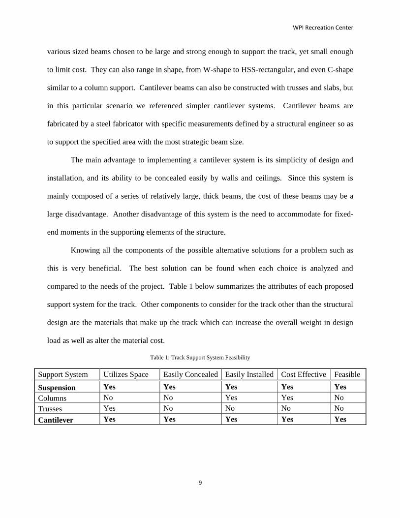
Knowing all the components of the possible alternative solutions for a problem such as
this is very beneficial. The best solution can be found when each choice is analyzed and
compared to the needs of the project. Table 1 below summarizes the attributes of each proposed
support system for the track. Other components to consider for the track other than the structural
design are the materials that make up the track which can increase the overall weight in design
load as well as alter the material cost.
Table 1: Track Support System Feasibility
Support System Utilizes Space Easily Concealed Easily Installed Cost Effective Feasible
Suspension Yes Yes Yes Yes Yes
Columns No No Yes Yes No
Trusses Yes No No No No
Cantilever Yes Yes Yes Yes Yes

WPI Recreation Center
10
Materials
One major component of our project and construction management in general, is the cost
analysis of all methods and materials used. When selecting materials it is crucial for the
designers to use the lowest costing materials without compromising structural integrity while
complying with all specifications. The current proposed track is composed of W10x19 girders
and W10x22 joists with three lanes of Mondo flooring, a railing to prevent users from injury, and
other basic materials used to encase the unit. The materials that are used in the current track
design could be carried over to the new proposed track, but an investigation into structural design
configuration as well as structural materials could provide some cost savings to the owner.
2.2.2 Long-Span Roofing System
The Recreation Center’s current roofing system involves a series of thirteen trusses
designed to support the suspended track, the roof deck, all the equipment on the roof, and all
variable live loads normally associated with building roofs such as snow load and wind load.
The existing design, which has been created by Cannon, the Architect on Record for WPI’s
Recreation Center Project, is presented in Figure 3. The current roofing system has been
designed by professionally licensed structural engineers to safely support all of the components
mentioned above, but if our project alters one component it may be necessary to reanalyze the
existing truss design to assess its adequacy. By altering the existing support system, the long-
span roofing system may become too heavy for the structural columns to support due to the
changes of the track design. It will be necessary to reanalyze these components to insure the
safety and integrity of the building.

WPI Recreation Center
11
Figure 3: Cannon’s Structural Truss
2.2.3 Massachusetts Building Code
For every construction project and structural design there are a set of standards in place
and enforced by the Authority-Having-Jurisdiction to ensure safety. For the Commonwealth
Massachusetts, there is a state building code which is supplemented with the provisions from
International Building Code (IBC) (Mass.gov, 2011). The purpose of the IBC is to ensure safety
of buildings by setting limits on design values for the structure design (IBC, 2009). For this
project the code of record is the 7th
Edition of the Massachusetts State Building Code (780
CMR), which is consistent with the actual project documents.
2.3 Project Management
Project Management is defined as the art and science of coordinating people, equipment,
materials, money and schedules to successfully complete a project (Oberlender, 2000). Many
owners find it difficult to manage construction projects because they don’t have the expertise, or
they don’t have the time to successfully oversee the entire construction process. For this reason,
owners seek help in construction management (CM) firms. CM firms specialize in project
management for all construction processes. CM firms can provide pre-construction services as
well as coordinate construction activities throughout the duration of the project. These firms
provide experience and knowledge that an owner may be lacking. The CM uses their expertise to

WPI Recreation Center
12
help the owner throughout the design and construction of their building. Hiring a CM allows the
owner to be involved, but maintain their responsibilities outside of the project. The owner
remains involved through attending weekly project meetings and staying in contact with the
Project Manager from the CM firm. This allows them to stay in the loop and have the say that
they need for the end product to be favorable for them.
One type of CM that is chosen regularly is a CM-at-Risk. This is the case for the
Recreation Center. The term CM-at-Risk identifies that the CM is taking on the project at a
financial risk to them. If the CM-at-Risk approach is chosen, the profit for the CM is “at-risk” if
the final cost of the project is over budget. This aspect of the CM-at-Risk approach is discussed
further in a later section, Cost, that details a GMP contract. With a CM-at-Risk, all of the
subcontracts on the job have a contract that exists between the CM and the sub. If there was no
“at-risk” the contracts would be made between the owner and the subcontractors, placing the risk
on the owner not the CM. When there is not risk for the CM, they are simply working for a fee
and not assuming any risk in the project (Oberlender, 2000).
For the WPI Recreation Center, WPI, as the owner enlisted the help of Project Manager,
or PM in Cardinal Construction. They represent WPI as the liaison between the architect
(Cannon Design) and the chosen CM-at-Risk (Gilbane). WPI does not always choose to use a
CM-at-Risk for construction projects, but they chose to execute the Recreation Center in this
manner for many reasons. One of which was that Cardinal has expertise in construction that very
few, if any, WPI employees have. Also, there is no one on the WPI staff that has the necessary
time to devote to fully managing a construction project. If an employee were to take on this
responsibility, they would have to drop all other responsibilities that they normally have. WPI
has appointed a representative within its staff in the Department of Facilities to oversee the

WPI Recreation Center
13
project. For the Recreation Center, WPI chose Mr. Alfredo DiMauro to be the contact point for
the Department of Facilities. He works with other operations managers to add their input and
oversee the construction on behalf of the campus. All of these professionals come together to
successfully bring the product that the campus is expecting at the end of construction. In order to
create a successful product, project meetings are held weekly to keep all parties on the same page
and guarantee that every party is updated on the progress of the project. These meetings are
crucial for communication between parties during the pre-construction and construction
processes. These meetings were attended by members of the group throughout the MQP and
gave insight to how the schedule and cost aspects of project management are integrated into a
project.
2.3.1 Schedule
Scheduling is one of the most important functions related to project management. When a
project is contracted to a CM firm, a completion date is set. For a CM-at-Risk, this completion
date is a contracted date that corresponds with the “at-risk” responsibilities. Maintaining a
schedule through constant updates ensures that the completion date is always in sight for the CM.
A schedule ensures the completion date is achievable from the first schedule that is made on the
job. The initial schedule created on the job is important for setting goals and placing realistic
guidelines on the schedule as a whole.
Gilbane completes what is called a “card trick” to make an initial project schedule with
the input of all or most of the subcontractors. In this method of creating an overall schedule, a
representative from each subcontractor is present so that every party can create the schedule
together. Most subcontractors will send a representative to speak on behalf of their scope of
work. This allows for everyone to be in the same room and visually see how the schedule is

WPI Recreation Center
14
going together. It gives each construction trade an opportunity to have an input. This helps to
avoid coordination problems in the future because many potential problems and conflicts are
recognized and handled at the very beginning. This also helps all parties to be involved very
early in the project and “buy into” creating a successful project because they are putting their
own feedback into the process.
Most CM firms, including Gilbane, have an employee who is dedicated solely to keeping
track of the schedule to ensure it is up to date during the construction process. It is that person’s
job to make sure that the schedule constantly reflects what has already happened in the field, as
well as portray an accurate projection of what is going to happen in the immediate and distant
future, based on the information they have been given. Each subcontractor submits their own
schedule, and it is the job of the CM to input that individual schedule into the master schedule.
Subcontractors and CMs also have regular meetings during the progress of the project to discuss
what is happening in the field and what they expect to happen; this also helps to keep the
schedule up to date. It is the job of the scheduler to sort through the schedule to ensure that the
precedence of different activities is properly entered in the software. When the project gets
moving, the scheduler continuously updates the schedule and reviews its logic to help guide the
project to successful completion. In the case of the Recreation Center, Gilbane’s scheduler
updates the schedule monthly. He gathers information from the members of the project team that
are on-site every day and updates the schedule based on the information he receives from them
(Salazar, 2011).
There are many different software programs that can be used to create a schedule, but
Primavera is one of the most commonly used to create a Critical Path Method based schedule
(The Bright Hub, 2011). Primavera is capable of tracking all the important aspects of a schedule

WPI Recreation Center
15
mentioned above, such as duration to each activity, a cost, as well as the relationships between
two or more activities. Primavera can track different aspects of the project besides schedule,
such as cost, contracts, risk management and document control items. It can do all of these tasks
own its own, but also through the integration with other programs such as E-business Suite and
JD Edwards Enterprise One (Oracle, 2011). For contracts, it can track the contract summary to
date, change orders, and payment processing rates. Pertaining to risk management, the software
can calculate confidence levels based on pitfalls commonly associated with the activities within
the schedule and predefined risk factors that are incorporated in the software. For document
control, it can help monitor communication processes such as RFI and submittal turnaround
rates, the number of issues resolved and unresolved, and different actions that must be taken to
keep the schedule on time (Oracle, 2011). Because of all the benefits that Primavera has to offer,
it is widely used.
An example of a Primavera schedule can be seen below in Figure 4 (Gilbane, 2011). It is
only one portion of a larger schedule. Also, it should be noted that past activities are not shown
on this schedule because Gilbane shows only current and future activities when they present a
schedule. On the left side of this figure is the list of activities. The activities are broken down by
different scopes of work (Design and Engineering, Procurement, Sitework, etc.). On the right
side of the figure, the duration of each activity is displayed by a horizontal bar that relates to the
date the work will be starting on the top of the screen. Red activities are critical path items and
green bars denote all other activities. One more item that can be identified in the figure is the
vertical blue line that is running through the right side of the figure. This vertical blue line
represents the current date. The presence of this vertical blue line helps each person who views
the schedule to comprehend where the project currently stands.

WPI Recreation Center
16
Figure 4: Primavera Schedule for Recreation Center (Gilbane, 2011)
Many schedules are created using the Critical Path Method (CPM). The CPM identifies a
chain of connected activities within a schedule that have zero float time. Two float definitions
are important for the scope of this project: total float and zero float. Total float is number of days
that an individual activity can be delayed without affecting the final completion date of a project.
When the total float of an activity is exceeded, the activity has the potential to become a critical
activity and affect the overall schedule because it will have zero float (Oberlender, 2000).
Quantifying and monitoring float values are important to avoid creating unnecessary critical
items, especially total float.
In order for the project to complete on time, the critical activities must finish on time. If
these activities do not get completed on time, the completion date will be pushed out
(Oberlender, 2000). An example of this can be found in the figures below. Figure 5 displays a
schedule that was created in November 2010. In this figure, it is clear that the mobilization for

WPI Recreation Center
17
the squash and racquetball courts, activity 2346 “Fab/Del – Squash Racquetball Courts” is set for
November/December 2010. In this schedule, the mobilization and the succeeding activities are
not critical. Activity 2346 is a green bar, which is called an Early Bar. This indicates that the
dates shown in Figure 5 are the earliest that these activities will begin. In reality, they could
begin later, due to their float time, and still finish without impacting the overall schedule. Also,
this schedule displays the precedence relationships that have been established between the
activities. In the column labeled “Successors,” numbers are displayed for each activity in the
respective row, these numbers represent other activities in the schedule that are going to succeed
the activity whose row they are in.
Figure 5: November 2010 Schedule (Gilbane, 2011)
Figure 6 displays a schedule that was created in August 2011. At the top of this figure,
the schedules regarding the squash and racquetball courts are displayed. These activities were

WPI Recreation Center
18
pushed until August 2011, and this made activity 2346, as well as the other activities regarding
the courts critical path activities. Critical path items are displayed in red; both
“Fabrication/Delivery – Squash/Racquetball Courts” (2346) and “Field Measurements of
Squash/Racquetball courts” (2345) are critical activities.
Figure 6: August 2011 Schedule (Gilbane, 2011)
In Figure 7 below, the critical path for the Recreation Center can be seen. This is the
critical path for the completion of the pool only. The complete critical path schedule shows a
much longer critical path for the entirety of the project. The length of the project is about two
years (May 2010 – April 2012), therefore only one portion of the critical path could be captured
in Figure 7. The schedule is consistently updated to reflect the current construction that is

WPI Recreation Center
19
occuring in the field. This ensures the CM and the owner that the critical path is still on track for
the final completion date.
Figure 7: Critical Path for the Pool (Gilbane, 2011)
In the case of the Recreation Center, the Critical Path, as well as the completion date are
both very important items. Because this is a WPI project, it must be completed in a timely
manner for many reasons. First, the school has promised its faculty, staff, and students that the
facility would be done by a certain time, Fall 2012. Not only is the community waiting for the
building, but they are also awaiting the restoration of the Quad. The Quad is the heart of many
student activites, as well as a space for Commencement, one of the most important activities
every year on the campus. Another reason, is that the Recreation Center is intended to be a major
selling point for the Admissions Office. As soon as it is completed, the actual building and its
amenitites can be displayed to incoming students. There is also the added benefit that when the
Quad is restored this area of the campus will be more asthetically pleasing than the current
conditions. Once the importance of scheduling in project management and for the Recreation

WPI Recreation Center
20
Center specifically was researched, it was important to understand how cost impacts project
management.
2.3.2 Cost
The initial construction cost of a project is determined by the bid that is submitted by the
Construction Manager. For the Recreation Center, a Guaranteed Maximum Price (GMP) contract
is in place. In this type of contract, a CM-at-risk agrees to a fixed completion date, as well as a
maximum price for the completed project. As previously mentioned, the CM will not make a
profit if they go over the contracted budget; they will pay the extra expenses out of pocket
(Oberlender, 2000).
In many situations, to guarantee that the contracted completion date is kept, an owner will
have liquidated damages written into the contract. Liquidated damages are the price that the CM
must pay for every day the project does not meet a milestone on time or the specified completion
date. This is another way for the CM-at-Risk to assume risk for the project (Allen, 1995). For the
Recreation Center, liquidated damages are not involved even though Gilbane is contracted as a
CM-at-Risk (Salazar, 2011).
A GMP can be created prior to receiving subcontractor bids or after. For the Recreation
Center, Gilbane chose to establish the GMP after awarding the subcontractor bids (Salazar,
2012). With this choice, the GMP is more accurate because the contractor has the advantage of
knowing specific pricing on each of the trade packages. Because of the accuracy of the GMP,
less contingency will be added to the overall cost because there should be very few imperfections
because the pricing for all of the subcontractor packages is known (Oberlender, 2000). For the
Recreation Center, as of winter 2011, there were 36 awarded packages in place. With a project of
this magnitude, most packages are awarded as early as possible, but some are not awarded until

WPI Recreation Center
21
later in the process. This can be because they are not critical to award immediately, or additional
scopes of work were deemed necessary by the owner later in the project.
2.4 Computer-Aided Engineering
Computer-aided engineering is a practice dependent on using a computer to build, design,
model, simulate and analyze engineering projects. Computer-aided engineering has been around
since the 1950’s, but is still gaining popularity as an application in the construction and design
fields. Over the years, the technology has been developed for many different types of fields and
specially designed programs that tailor to a specific trade. A major leader in the development of
these programs is Autodesk (Autodesk Inc., 2011). Autodesk is a company that makes over 50
programs that manufacturing, architecture, building, construction, and media and entertainment
industries use (Autodesk, 2011). Autodesk’s programs are very popular today due to the open
application programming interface (API), which allows easy file sharing between Autodesk
products; file share is great for the construction field where many different people are involved
in one project.
2.4.1 Robot Structural Analysis
Among the many types of programs Autodesk offers, Autodesk Robot Structural Analysis
is used by structural engineers to aid in the analysis of buildings. “Autodesk Robot Structural
Analysis (Robot) is a single integrated program used for modeling, analyzing and designing
various types of structures. The program allows users to create structural models, to carry out
structural analysis, to verify obtained results, to perform code check calculations of structural
members and to prepare documentation for a calculated and designed structure” (Autodesk Robot
Structural Analysis - Getting Started Guide, 2010). Robot uses an open API which allows the
files created in Robot to be transferred to other programs such as Autodesk Revit Structures,

WPI Recreation Center
22
another open API program. Autodesk Revit Structures is a part of the Revit platform for
Building Information Modeling.
2.4.2 Building Information Modeling (BIM)
Building Information Modeling, more commonly known as BIM, is “an electronic
representation of a facility for the purpose of design, analysis, construction and operation”
(Klancnik, 2009). Companies use 3D modeling software such as Autodesk Revit and
Navisworks, to create and/or review their BIM models. Some companies create the models
themselves using Autodesk Revit, others may receive a model made by another company and
they use Navisworks to review and coordinate the building. The 3D geometric models are
combined with additional information, such as time or money, to create the most unique
applications of BIM. The idea of trying to use computer-generated isometric objects in
construction is not new. The first three-axis computer models were constructed in the 1950s
(Klancnik, 2009). At this time there was no practical software for these models to have any sort
of everyday value. Today, BIM is the most popular construction management and design tool on
the rise. In the 2009, SmartMarket reported the percentage of projects using an aspect of BIM in
construction went from 28% in 2007 to 48% in 2009 (Klancnik, 2009). The same report
concluded that the number of U.S. contractors using BIM has almost quadrupled over that same
time period.
BIM continues to grow because its greatest asset is that it can be used within all phases of
construction. It is not another program that is specialized just for contractors, or just for
architects, or engineers. Figure 8 shows how BIM can be used by the owners, the architects,
engineers, contractors, and sub-contractors, all putting in their own information and detail into

WPI Recreation Center
23
the model so that it becomes an overarching work environment that can lead to improved
accuracy of information and increased construction efficiency.
Figure 8: BIM Contribution Breakdown (Partridge, 2011)
BIM does not change the roles of the players within the project team, but it plays a
significant role in coordinating the different trades to avoid any conflicts found in the proposed
design ahead of time. Initially, it takes a lot of work to set up the BIM model with all the
different information, but when done correctly it gets everyone on the same page so that
coordination problems can be solved ahead of time.
When issues are found in a project and an alternate design may be needed, BIM helps cut
down on the time it takes to propose and evaluate options. Designers can more easily propose an
alternative design and instantly see how it fits into the construction and assess its impact on the
rest of the building. The builders can quickly look at the proposed change and takeoff quantities
for the materials and the man power required to build the new detail. Then the contractor can
quickly access all the information provided and generate a cost estimate for the proposed change,

WPI Recreation Center
24
and investigate how it will affect the schedule of the project. In the case of the WPI Recreation
Center, the BIM model is used mostly for visualizations of how the building will come together.
In our project, the team will use the model for structural, cost, and schedule analysis.
Uses in Project Management
Because BIM is still relatively new, not all companies are fully functional with BIM. Its
usage is still growing and on most jobs in 2011, it can be found that the BIM model is used as a
tool mostly by the construction managers (Klancnik, 2009). As of now the major uses of BIM for
general contractors are visualization, coordination, 4D models, and 5D models (Klancnik, 2009).
It is not yet to a point where the structural and mechanical engineers update their portion of the
model, and the sub-contractors update their portions so that the model works as a tool to
integrate the work of everyone. As its usage continues, BIM is expected to reach that potential in
the coming years.
Visualizations are one of the main uses for BIM because they provide an easy way for
everyone to get on the same page on a conflict or concern. Sometimes the 2D drawings do not
depict or show an issue that may be in the field, or maybe the owner is not as familiar with the
drawings as everyone else. When the issue is investigated using BIM, anyone who was looking
at the building for the first time would easily be able to understand what they were looking at and
what the issue maybe. This type of clarity can cut down on the amount of time that an issue may
be debated; thereby, cutting down on meeting times significantly.
Coordination is another major use of BIM by general contractors. Coordination can be
between trades, or even the coordination of the job site. At the beginning of a project,
coordinating how the job site will be set up is always a big concern. This is because there are
property lines to deal with, along with making sure material deliveries are possible, and many

WPI Recreation Center
25
other coordination issues that the owner will have questions about. With BIM the site plan can be
clearly demonstrated to everyone, including the location of the trailers, materials storage, and
how material deliveries will be made, etc. It is a great way to clarify the set-up of the site, or how
the building should be orientated on the property. For example, Figure 9 shows a site plan that
lays out the locations for the cranes, trailers, dumpsters, gates, etc.
Figure 9: BIM Site Plan (Knutson, 2011)
Coordination between the different subcontractors is another current use of BIM by
general contractors. A report can be run within BIM that detects any and all interferences
between the geometric shapes. A perfect example is laid out in the Contractor’s Guide to BIM
where there might be an interference with the way the plumbing and HVAC equipment is
supposed to be installed (Klancnik, 2009). With BIM, the plumbing and HVAC sub-contractors
can be shown the issue through the model and use the model to propose a new design on how to
install the equipment. Figure 10 shows the conflict between the proposed location of the purple

WPI Recreation Center
26
pipe, and that of the grey hangars for the red conduit. Any type of interference like this can be
found early on in the project with the use of BIM.
Figure 10: Interface Detections (Hope, 2010)
Without BIM, this issue may not have been discovered until the materials were on site
and ready to be installed; therefore, causing a delay in the project as well as a potential change
order. For the Recreation Center, BIM is not a contractual requirement. Cannon provided a BIM
model with no contractual ties in it to Gilbane. Gilbane then refined the model so that they could
use it as clash detection for the mechanical, electrical, and fire protection trades.
4D and 5D models are the most current uses for BIM by general contractors. The most
popular and practical model is the 4D model. The 4D model consists of taking the 3D model and
adding in the element of time. The 4D model works by importing the project schedule into the
3D model. Combining the schedule and the model, causes the sequence of activities from the
schedule to be linked to corresponding portions of the 3D model. This is a good tool for
visualizing the progress of a building over time, as well as, exploring the effect on the schedule
when a certain area of work is delayed or changed. A 5D model is created by expanding the 4D
model by adding the element of cost. Currently, this method is not used as frequently because the

WPI Recreation Center
27
types of estimating software that are used are not compatible with BIM. The advantages of this
method in the future will be the ability to quickly assess the impact to the schedule and cost
when an area of work is changed. This will help to more accurately project the end date and final
cost of each project. In the project, our team will be using the WPI Recreation Center model and
schedule to create a 4D model that shows the existing and new design. The group will also look
into the feasibility of creating a 5D model by adding the costs of the new and existing track
designs.
Uses in Structural Engineering
Although BIM is primary used by construction managers, structural engineers are quickly
realizing its potential as well. BIM is enticing for engineers because it uses an object-oriented
programming paradigm (Nelson and Schinler, 2008). This means that the 3D model of the
structure possesses all the information and functionality of each of its members. For example it
contains information pertaining to its material, section properties, location in the building etc.
From a structural point of view BIM is used for coordination, documentation, analysis and
design.
Similar to project management, coordination of all the aspects of the project assists the
structural engineer as well. Coordination amongst the architects, structural, and mechanical
engineers results in better decision making based on actual and current designs. This
coordination also allows for better updating and changing between programs and designs. This
results in reducing time and conflicts because everyone is using the same model.
Documentation is the only aspect that the structural engineers have complete control over
because it is based on their work and analyses (Nelson and Schinler, 2008). Since the BIM model
can hold all the information and functionality of each member in the structure, it can easily be

WPI Recreation Center
28
found all in one place. This makes documentation much easier because everything is in one file.
This kind of documentation is also good because if changes are made later in the project, the
changes are consistently applied to the entire design and documentation. However
documentation does have its flaws in BIM. Repeating members in a structure will be
documented individually, when traditionally usually a single drawing would have sufficed. Also,
many structural engineering firms take pride in the way they present their drawings, and BIM has
limits for the presentation of the drawings.

WPI Recreation Center
29
Chapter 3 - Benchmarking the Current Design
A critical part of progressing forward to alternative design is to first understand the
existing design, and then modify from there. This chapter focuses on the uses of Revit to create a
model unique to this project’s needs, a baseline cost estimate both on the given information and
RS Means, a schedule of the existing design and a 4-D creation of the existing design through
BIM. All of these aspects give this project a fair understanding of the different dimensions of the
existing design which all start with the Revit Model.
3.1 Revit Model Creation of Existing Design
Revit was used to gain an understanding of the track structure and its relationship to the
Recreation Center, as well as provide a base for modeling and analyzing the alternative design.
Revit was initially used as a visual aid to assist the group during 2-D visual restriction. The
lengths and beam sizes that are mentioned in the structural plans were translated into Revit for a
3-D full visual aid. It was altered into an interactive representation that could be analyzed from
both structural and project management perspectives. The structural component of Revit allows
the structure to be transformed into an analytical model which can be analyzed in Robot.
Additionally, Revit has many components that supplement project management such as
scheduling and cost.
3.2 Creation of Baseline Cost Estimate Based on Given Information
In benchmarking the current design through a cost analysis, the ease of integration
between Revit and RS Means cost data was displayed. Revit readily provided the information that
was necessary to utilize the cost data provided by the RS Means book.

WPI Recreation Center
30
Revit easily exported the existing track steel information into three different schedule
spreadsheets (steel framing, columns, and trusses). Revit was able to give the type of beam,
length in linear feet, and volume of each steel member. This information was used, in
congruence with the cost of the steel package provided by Gilbane to create a unit cost for the
steel (Gilbane, 2012). Complete Tables with all of this information can be seen in Error!
Reference source not found.. Below, Figure 11 displays a step-by-step flowchart on the process
behind exporting the quantities from Revit. A more detailed document for extracting information
from Revit and placing it into an Excel spreadsheet for analysis can be seen in Error! Reference
source not found..
Select the View Tab
in the Revit Model
Select the
Schedule Button
From the
Dropdown Menu
Select “Schedules/
Quantities”
Select the Type of
Schedule
Choose the Fields
Required
Export the
Schedule
Figure 11: Flowchart for Exporting Schedules

WPI Recreation Center
31
First, a baseline price was created from cost data for the actual project. Table 2 below
provides a breakdown of the total tonnage of steel as allocated to the columns, the framing, and
the roof trusses. Knowledge of the total steel package cost, obtained from a Gilbane project
meeting, and the total tonnage of steel allowed for the unit cost ($/ton) of steel to be determined.
This calculation is also summarized in Table 2. The tables with individual calculations to
determine the total quantities of steel columns, framing, and trusses, as referenced before, can be
found in Error! Reference source not found..
Table 2: Unit Cost Breakdown of Total Structural Steel
Quantities of Total Rec. Center
CF TONS
Structural Steel Columns
795.26
194.84
Structural Steel Framing
3,367.10
824.94
Structural Steel Trusses
610.00
149.45
TOTAL
4,772.36
1,169.23
Cost
Structural Steel Contract ($) $ 3,497,809.00 (includes labor)
Cost/Ton $ 2,991.55 (includes labor)
After the unit cost of steel in $/ton was calculated for the entire building, information on
only the track steel was exported from Revit. In order to extract only the track information, a
separate Revit model was saved from the Cannon model by deleting all other steel elements in
the building except for the track steel. An estimate for the cost of the track steel was determined
by multiplying the tonnage of steel supporting the track by the unit cost of steel in $/ton. The
breakdown for this analysis can be seen in Table 3 below.

WPI Recreation Center
32
Table 3: Unit Cost Breakdown of Track Steel
Quantities of Existing Track and Roof Design
CF TONS
Structural Steel Columns
201.16
49.28
Structural Steel Framing
300.57
73.64
Structural Steel Trusses
602.58
147.63
TOTAL
1,104.31
270.56
Cost
Cost/Ton $ 2,991.55 (includes labor)
Cost of Existing Track and Roof $ 809,381.65 (includes labor)
After determining the cost of the track steel based on the actual total cost of the steel
package, the amount of steel exported had to be adjusted for to add welding to the trusses and
connections. These percentages were assumptions made from instructions from RS Means. RS
Means is fully discussed in the next section. Table 4 is a summary table of the adjusted estimate
with the additions of welded trusses and connections. The total cost of the existing track was
found to be approximately $922, 700.

WPI Recreation Center
33
Table 4: Complete Estimate for Existing Design with Adjustments from RS Means
CF TONS
Structural Steel Columns 201.16 49.28
Structural Steel Framing 300.57 73.64
Structural Steel Trusses 602.58 147.63
TOTAL 1,104.31 270.56
10% for connections 27.06
4% for welded trusses 10.82
TOTAL (tons of steel) 308.43
Cost/Ton $ 2,991.55
Cost of Existing Track and Roof $ 922,695.08
When the original estimate was completed, a second estimate was prepared using a
quantity take-off and discrete cost data from RS Means (RS Means, 2009). Both estimates were
based on the model provided by Cannon.
3.3 Creation of Baseline Estimate Based on RS Means
For creating the cost estimates in this project, Gilbane provided baseline information that
was very useful because it provided the means to create unit costs for steel that were described in
the previous section. To complement the information given by Gilbane, RS Means was used as a
main resource used in creating the cost estimates for this project. The book provides up-to-date
cost data information. It also provides adjustments for different areas of the country if necessary.
It is a widely used estimating tool due to its diversity. It offers information in many different
sectors: home improvement, commercial construction, residential construction, facility
management, green construction, and educational construction (RS Means, 2012).
In the research process, RS Means was found to be a resource in many educational
papers: Why is Manhattan So Expensive? and Review of Current Estimating Capabilities of the

WPI Recreation Center
34
3D BIM. It was also found as a reference in a U.S. Government document, Appendix B: Energy
and Construction Cost Estimates. The use of RS Means by many reliable sources made it a good
option for the cost estimate created in this project.
3.3.1 Estimate Process Based on Cost Data
The difference between RS Means and using the steel package price was that estimates
for line items such as steel connections, welding, and overhead and profit had to be made.
Instructions for all of these items were provided by first pages of RS Means, called “How to Use
the Unit Price Pages”, that fully detailed how to use the information provided in the book. Steel
Connections were added by applying 10% to the overall cost and welded trusses were accounted
for by applying 4% to the overall cost. Overhead and profit percentages had to be added
individually to each aspect of the project that was available to us (Material, Labor, and
Equipment). If an estimate for a real construction job were created, a much more detailed
overhead and profit adjustment would be made. Contractors can add overhead and profit to many
different areas individually. These areas include shop labor, field labor, engineering, office
support, material, and equipment (Turgeon, 2012). The estimate presented for this project did not
get this detailed given the scope of the project. A basic flowchart describing how the RS Means
cost data was used can be seen in Figure 12 below. A more detailed description of how the RS
Means text was interpreted can be seen in the step-by-step methodological description in Error!
Reference source not found..

WPI Recreation Center
35
Organize Exported
Data from Revit by
Beam Size
Look Up Cost Data
in RS Means for
Each Beam Size
Look Up Crew Info
to Apply to Labor
Costs
Apply O&P to
Material & Labor
Apply Additional
Factors to Overall
Estimate
Add All Factors
Together
Figure 12: Flowchart for the Use of RS Means
A numerical example showing how the latter part of the flow chart can be put in place
can be seen in Table 5 below. This table displays how each column member was accounted for,
as well as the addition for overhead and profit. The 10% is added for the material and equipment
is for overhead and profit only.

WPI Recreation Center
36
Table 5: Estimate for Steel Columns Including Overhead and Profit
COLUMN COST BREAKDOWN
Labor Cost/Unit Total Labor Cost Material Cost
Equipment Cost
HSS1.900x0.120 $ 7.82 $ 6,176.92 $ 4,817.48 $ 1,761.14
W12x120 $ 6.30 $ 266.72 $ 8,382.00 $ 76.62
W12x152 $ 1.74 $ 73.58 $ 13,335.00 $ 80.86
W12x40 $ 5.87 $ 345.12 $ 4,853.75 $ 99.43
W12x53 $ 5.87 $ 1,231.86 $ 17,325.00 $ 354.90
W12x58 $ 5.87 $ 165.20 $ 2,323.32 $ 47.59
W12x65 $ 5.87 $ 2,850.40 $ 40,088.12 $ 821.20
W12x72 $ 5.87 $ 2,441.73 $ 34,340.62 $ 703.46
W12x87 $ 6.19 $ 262.12 $ 6,096.00 $ 74.93
W12x96 $ 6.19 $ 418.99 $ 9,744.00 $ 119.77
Total $ 14,232.64 $ 141,305.30 $ 4,139.91
O&P Add 10% Already Adjusted $ 155,435.82 $ 4,553.90
Total Cost of Columns $ 174,222.36
Another add-on to the RS Means base estimate was inflation. This was added to the
estimate because the RS Means book that was used was 2009 based and the steel was erected in
2011; the two year difference had to be accounted for through inflation rates. Using the ENR-
CCI (Engineering News Record - Construction Cost Index), it was determined that the equivalent
inflation rate from 2009-2010 was 3.15%. This number has remained approximately constant for
the past 10 years (ENR, 2011). When taking the mentioned factors into account estimates for the
three individual categories of the steel were created and combined to create the total estimate.
Using the cost of the columns, steel framing, and trusses we determined our final steel
estimate to be $1,060, 400. This was a difference of 15% in comparison to the original estimate
of $922,700 that was based on the steel package submitted to Gilbane. The cause of variance in
the estimate could be due to many reasons. As stated before, many estimates on items such as

WPI Recreation Center
37
connections and for welded trusses were assumed based on RS Means and are not exact. Also,
the adjustment for inflation may not be exact. The value of 3.15% was based on information
from ENR and is an equivalent value, not a value directly from 2009 to 2010 (ENR, 2012). To
adjust the cost for the two years from 2009 to 2011, we added (1.0315)2. The breakdown of our
final estimate can be seen in Table 6 below.
Table 6: Estimate of Existing Design Using RS Means
OUR ESTIMATE OF EXISTING
Our Estimate (no O&P) $ 905,526.37
10% for connections $ 90,552.64
4% for welded trusses $ 36,221.05
Total w/o Inflation $ 1,032,300.07
Total Cost of Our Estimate for Existing w/ Inflation $ 1,064,881.52
Error 15%
3.4 Schedule Investigation of Current Design
In order to help analyze the existing design and the alternative design two schedules of
the steel work were developed. One schedule was a baseline of the existing design and the other
was a schedule created to put a time frame to the alternative design. The first step was to develop
a schedule that involved only the track-area steel pertinent to the project. Because the project
only involves the columns, framing, and trusses that make up the track area of the Recreation
Center the entire Gilbane steel schedule involves more activities than are needed for the
investigation.
To develop the project-specific construction schedule the group started with the master
schedule of the entire project from August 2010 which was one of the project’s early projected
schedules. This schedule included anything that had not been completed from the current date

WPI Recreation Center
38
until the end of the project. Activities ranged from site work, and concrete, to pool installation,
and floor finishes. Then, all the steel-specific activities were broken down to create an all-steel
Primavera schedule based on the August 2010 start and finish dates. To make the schedule more
accurate for the project, any steel activities that did not pertain to the columns, framing, or
trusses around the track were eliminated. This schedule illustrated roughly how long Gilbane had
originally estimated the track steel would take to be installed. Of course, as a project progresses
there can be changes to the schedule due to fabrication delays, weather delays, and slow
production, etc. The next step was to compare the actual time duration for erection of the track
steel to the August 2010 projection, to see if the installation took longer or went faster than they
originally suspected. WPI has used four webcams at four different locations around the
Recreation Center to monitor the progress. With access to these images a spreadsheet was
created involving four photos from each day that steel for the track area was being installed. A
screenshot of the assembled time lapse photo spreadsheet can be seen below in Figure 13.
Figure 13: Time-lapse Photos Spreadsheet

WPI Recreation Center
39
These photos aided in determining when the steel actually started to be erected and when
it was finished. It also revealed the production rates per day of the columns, framing, and trusses
which was very beneficial for developing the schedule of the alternative design. On a second
spreadsheet the steel activities were broken down into five major activities and the quantity of
each type of steel installed on a given day was estimated and recorded. The five major activities
were trusses, bracing/framing, columns, track framing, and track cables (Table 7).
Table 7: Existing Production Breakdown
This breakdown facilitated the creation of a project-specific Primavera schedule of the
elapsed time for the installation of the existing track steel (Figure 14).

WPI Recreation Center
40
Figure 14: Existing Design Primavera Screenshot
The actual time it took to erect the steel for the track and the projected time were quite
similar. The difference between the two schedules was about one week’s time, the added length
was due to a couple lost days because of the amount of snow Worcester received in the early
months of 2011. Using the time lapse photos to compare the actual and projected construction
schedules helped to understand the process for installing the steel. Each truss was delivered in
two sections and assembled on the ground. The steel erectors started at one end by installing the
columns and bracing for two column bays. Once they erected and braced the two column bays,
they installed the trusses for one of the bays which included three trusses. They repeated this
process from one end to the other, making sure to have installed one more bay of columns and
bracing than trusses. Figure 15 shows the steel installation proceeding from the left to the right
by installing the columns and bracing first, then the trusses, and finally the track framing and
cables.

WPI Recreation Center
41
Figure 15: Progress Photos
These photos were also beneficial because they provided a means to estimate the average
production per day for each piece of the steel structure. The most important production rate was
for the installation of the trusses. Trusses were the most important because they are the largest
steel members and none of the other steel in the track area could be installed until the trusses for
a bay were installed. The workers were able to install on average two trusses, four columns, and
six pieces of bracing per day. The workers could install up to eleven bays of lighter weight track
framing in a day. But because the rest of the construction could only complete one bay each day,
the workers only installed one bay of track framing and cables each day for consistency. In all,
the installation of the track area steel took six weeks, while the projected installation time
obtained from Gilbane’s schedule was five weeks.
3.5 Creation of 4-D BIM
Integrating the schedule into the BIM was necessary to create a 4-D model. This was
completed through “Phasing” within the Revit model. The process was learned from an MQP
completed in the previous academic year by Fournier et. al. We created four phases for the
existing design based on the percentage completed for the track area. Because the overall

WPI Recreation Center
42
schedule was six weeks, screen shots were taken at one and a half weeks, three weeks, four and a
half weeks into the process, and final construction. The phases referred to 25%, 50%, 75% and
100% completion time-wise. Below, Table 8 breaks down each phase through different
components. It displays the phase, the date the phase is depicted on, and the completion
percentage of steel based on the tonnage that has been erected.
Table 8: Phase Breakdown Information
Breakdown by Phase
Phase Date Steel
% Complete Tonnage % Complete
25% 3/7/2011 20.49 7.50%
50% 3/17/2011 109.44 40%
75% 3/27/2011 179.82 66%
100% 4/6/2011 270.56 100%
Figure 16 shown below is the track at 25% completion. The percentages were based on
the timing of the schedule. This figure is shown on 3/7/2011, 25% complete schedule wise. At
this 25% schedule mark, there was 20.49 tons of steel completed. That is only 7.5% complete in
terms of steel tonnage. This could be due to many things: weather, holds on certain parts of the
steel, among other reasons. Figure 16 depicts the beginning stages of the track construction on
the Morgan side of the building.

WPI Recreation Center
43
Figure 16: Phase 1 - 25% of Track Complete
When the schedule is 50% complete, there is much more steel up. Figure 17 below shows
the progression at 50% complete. There are many more trusses erected, as well as 3 complete
column spans. At 50% done, this Phase has 109.44 tons erected. That is about 37% more steel
erected than Phase I and 40.44% of the total track steel, work-wise. Phase II is depicted on
3/17/2011.

WPI Recreation Center
44
Figure 17: Phase 2 - 50% of Track Complete
Figure 18 is Phase 3 – 75% complete. At 75% complete, it is visible that the track is very
close to completion. At this point in time, there are 179.82 tons of steel erected. This is only 34%
from completion in terms of work.
Figure 18: Phase 3 - 75% of Track Complete
The final phase is named “New Construction.” For the steel work, this phase includes the
remaining 33% of steel erected. It is in this time period that the remaining columns and track
framing are completed. This can be seen in Figure 19 below.

WPI Recreation Center
45
Figure 19: Final Construction Phase of Existing Track
The tonnage of the steel from each phase was determined by filtering the schedule
information. This included a few additional steps in Revit. The steps for this process are also
included in Error! Reference source not found.. Creating the 4-D model was the last step in the
benchmarking of the existing design. At this point, the next step of the MQP, to create and
analyze the alternative design could begin.

WPI Recreation Center
46
Chapter 4 - Alternate Designs
Once the existing track had been investigated thoroughly, and alternative track design can
be proposed. The following chapter goes into the detail of how the alternative track was created
through the structural evaluation, the cost development, and schedule formation. There were two
alternatives attempted through this project; the cantilever approach and simple beam approach.
Both of these designs were based off of the existing design with the elimination of the hanging
supports.
4.1 Structural Evaluation
The structural evaluation of the alternative design tested two different approaches. Each
approach eliminated the hanging supports on the inner side of the track. The first approach
considered using cantilever beams that spanned perpendicular to the outer wall beams and inner
beams of the track. This method did not work because in order for the cantilevers to have enough
moment resistance, they exceeded the height restriction of 44”, which then became an issue for
head clearance on the fourth level (gym floor). This inspired our second approach of changing
every other perpendicular cantilever beam to a simply supported beam. To facilitate this change,
the lengths of the inner beams were extended to span the same length as the outer beams or
girders. This approach did not eliminate the cantilever beams all together, it merely reduced
their number because substituting simple beam configurations for cantilever configurations
dispersed the loading across the track and allowed the cantilevers to have a smaller member size.
These two approaches were investigated through the use of spreadsheets and hand calculations.
However another component of each analysis used Robot as a computer-aided design resource to
solve indeterminate equations and gauge approximate results for the hand calculations.

WPI Recreation Center
47
4.1.1 Existing Design Criteria & Adjustments
During the calculation phase of the alternative design some alterations were made to the
member design process such as the loading scheme, change to the construction load, and minor
alterations to the beam lengths and design. In addition to these design alterations, there is a
labeling system to the orientation of the project. Through the remainder of this project, the
Recreation Center is broken down to different components and each section has certain labels.
Instead of referencing the direction of each building, this project labels each side by the major
landmarks associated with each direction. For example, the West side of the building is next to
Football field, so throughout this project, the West side is also known as the Football side.
Additional references associated with the directions of the Recreation Center are the Softball side
(North), Quad side (East) and Morgan side (South).
As previously stated, the track system consists of steel beams that support metal decking,
a concrete slab, and various sections of conduit piping for MEP (Mechanical, Electrical,
Plumbing) systems. All of these loads must be incorporated into the factored design loads for
the beam which determine the beam’s required strength and resulting size. In order to insure that
the dead and live loads were properly accounted for, a conservative approach was used. A design
strategy was adopted that if one beam were to fail, then the loads would still be supported by the
other beams within the area of the failure. This was achieved by creating loading schemes for
each section of the track. For example, Figure 20 below shows the loading scheme for the
straight away section of track along the wall of the Recreation Center facing the football field.
The end beams were designed to support half the tributary area of the various loads applied, and
these beams were designed first.

WPI Recreation Center
48
Figure 20: Girder loading scheme across tributary width (Football Side)
Next the middle beams were designed to support the tributary area on either side of the
beam. The middle beams not only support the various dead and live loads across their tributary
width, but also the pick up the loading from the end beam. Figure 21 is an example of the
loading scheme of the one of the girders located between the columns on the Football side of the
track. When the loading of the girders were calculated, they were designed to support half the
tributary area of the track floor, as well as the middle beam’s reaction and the reactions from the
beams on the other side of the track, if any where present.

WPI Recreation Center
49
Figure 21: Girder Loading on Football Side of Track
The Quad side of the track is similar to Figure 21, but had beams attached to both sides of the
girder. In this scenario, the reactions due to the beams on the other side of the track were
calculated using factored loads to ensure that the girder would not only sustain the track loadings
but also the other side if needed. The rest of the loading schemes can be seen in Error!
Reference source not found..
The track framing was designed for different deflections including strength and
deflection performance during construction. Typically the construction load is assumed to be 20
psf due to the workers and equipment, but because the track is a limited area, the construction
load was decreased to 10 psf. It is a safe assumption because it was not possible to
accommodate a large number of workers and equipment within the allotted space.
These design criteria and adjustments created a foundation for the track design for the
alternative approach. Due to the fact that the alternative design does not have the hanging
supports, some alterations to the beam lengths and layout geometry were necessary. The first

WPI Recreation Center
50
attempt at an alternative design was a cantilever based model with strengthened beams
perpendicular to the track.
4.1.2 Alternative Design – Cantilever Approach
The first attempt at an alternative design was a cantilever method with the same
configuration as the existing design, but without the hanging supports. Figure 22 represents a 3
dimensional view of the design and Figure 23 represents the framing plans of the cantilever
method. In order to compensate for the lack of hanging supports, recalculations of the
supporting beams were made to sustain the new added weight.
Figure 22: Cantilever Approach (Trusses Omitted)

WPI Recreation Center
51
Figure 23: Framing Plans of Cantilever Method

WPI Recreation Center
52
This new alternative created 11’8” cantilevers spaced every 9’ 8” in which each
cantilever took on a large moment force from the various forces acting on the member. It was
soon discovered that these cantilevers created too much moment and their respective depths
would be a hazard to head clearance on the basketball courts. Table 9 below shows some of the
member sizes of the various beams of the first attempt. The calculations for this method can be
found in Error! Reference source not found..
Table 9: Cantilever Approach Member Sizes and Forces for Football Side
Member Sizes (Football Side)
Beam Type Beam Size Force (k) Moment (ft.k)
End W10x12 0.012 0.14
Cantilever W21x44 10.32 482.51
Girder W18x40 22.96 268.37
There were not any W-shaped beams that could withstand its specified moment as well as
fall within the 44” height restriction, which meant a rounded HSS beam would have to be used.
The substitution of a rounded beam would also not work in this scenario because that type of
beam could not support the various vertical live and dead loads associated with the track. All of
these findings pointed in one direction, to reconfigure the alternative design by minimizing our
cantilevers and moment reactions.
4.1.3 Alternative Design – Simple Beam Approach
The second design that was attempted was a modified version of the Cantilever
Approach. It was modified by alternating the cantilevers to a simply supported beam. Figure 24
represents the framing plans of the Beam approach and Figure 25 represents a 3D Revit model of
the framing plans. The simply supported beams were located at the mid-span of each girder and
end beams. The end beams were combined to form a longer beam, the same length as the girder
it is parallel to. This eliminated the moment on the girders from the original cantilever design.

WPI Recreation Center
53
Figure 24: Framing Plans of Beam Approach Alternative Design

WPI Recreation Center
54
Figure 25: Revit Model of Beam Approach Alternative
The calculations for the process were done through hand calculations, spreadsheets, and Robot
Structural Analysis. The hand calculations, located in Error! Reference source not found. were
used to show an example of each type of beam calculated with the spreadsheets. The
spreadsheets were used to simplify the timely process of writing out the procedure used to design
the beams. The spreadsheets also allowed for quicker checks of member selection and
calculations, these can be seen in Error! Reference source not found.. Robot was used to
calculate reactions for fixed end beams, as well as member verification of selected beams. These
specific uses of Robot are detailed in the next section. Each Robot function used was checked
with hand calculations or spreadsheets to verify the accuracy of the operation.
WPI Recreation Center
55
4.1.4 Robot, Structural Analysis Program
Robot was used as a computer-aided engineering tool throughout this project. Prior to the
start of the project, no group member had ever used this program before, and so the scope of
work included gaining familiarity with the use of Robot for structural modeling and analysis.
This learning process involved reading the user guide, watching videos online, and working with
the help function within the program. These initial resources were a good starting point but did
not provide the in-depth instructions of what the group felt was necessary to use the program for
their project. These established resources gave more of a general overview of individual
functions but didn’t relate the functions together. Instead a trial and error process or “playing
around” with the program was relied upon to gain insight into the relationships and interactions
between two or more functions. This interactive learning method proved to be more effective
than searching for guidance from established resources. The outcomes of the process are detailed
in the below paragraphs and shown in the Error! Reference source not found., through Error!
Reference source not found. as tutorials.
After gaining a general understanding of some specific functions the group was able to
use Robot throughout the project. Some of the main functions the group used were solving
indeterminate structures, verifying that an appropriate steel member was being used for non-
composite beams, and modeling structural members in 2-D or 3-D.
Originally it was thought to transfer the Revit model for the alternative track design that
was created by the group, into Robot; however this translation of information proved to be
problematic. Due to the limited knowledge about Robot, the group was unable to make sense of
how to make use of the transferred structure in Robot. The interoperability with Revit Structures
and Robot worked correctly, however once in Robot, it was confusing of how to proceed with the
model. Because the design was complex, it was difficult to accomplish the desired tasks through

WPI Recreation Center
56
a trial and error process. In order to make use of the program, the group decided to explore some
specific uses Robot as a learning tool.
The simplest model to use in Robot was when only one beam was transferred. This was
tested by transferring beams, a combination of beams, and larger combinations of beams from
the Revit model to Robot. Once in Robot, one beam was easier to work with due to the simplicity
of having only one beam. From this point the group only used one beam at a time in the program.
By only using one beam, the group could control the unknown variables of the program better. A
disadvantage of only using a one beam model, the group had to create much more models than if
all the members were combined into a frame design. Future users should experiment using a
frame design with multiple members, to reduce the amount of models needed. Robot also has a
function to allow the user to build and create beams in Robot itself. This proved to be easier
when using Robot because the program only allows transfers from Revit if the programs are
linked together. The group found it easier to create the model in Robot to ensure it was the right
dimensions and maintained the correct properties. An example of how to build a beam and
control the properties can be seen in Error! Reference source not found..
After learning how to build a beam in Robot, different loading schemes were applied to
solve for the reactions, deflections, displacements, stresses, and forces. These features were
useful when solving for the reactions of the girders. The girders were fixed at both ends making
them indeterminate structures, which if solved by hand would be timely and complex. With the
use of Robot it was simply a matter of applying the correct loading schemes and clicking a few
buttons. Error! Reference source not found. illustrates the application of applying different
loading schemes to a beam. This function was used for solving the indeterminate structures for
the alternative design, for example the girders. To make sure Robot was correctly determining

WPI Recreation Center
57
the reactions and that the group understood how to apply the loads correctly, a simple model was
tested both with hand calculations and Robot. This can be seen Error! Reference source not
found.. All the girder reactions can be seen in Error! Reference source not found..
Once the loads were applied to a beam it was analyzed as a non-composite beam to check
for an appropriate beam size. This was done using the Steel Design layout. Steel Design is a
function in Robot, which can be used to check appropriate beam sizes. This function offers two
different calculation methods LRFD and ASD that can be combined with alternative verification
methods, like flexure, compression, and shear. For this project LRFD was chosen as the
verification method for all beams. Originally the group wanted to use Robot to use the Steel
Design function for all the beams in the structure; however based off the research and literature
available this idea proved to be unsuccessful because the group was unable to find the process to
model this type of beam necessary for composite action. The Steel Design function was only
used for the cantilever middle beams because they are non-composite beams. An example of
how to use the Steel Design function in Robot can be seen in Appendix O. To make sure the
group understood how to interpret the Results of the Steel Design function, they compared the
Robot results to hand calculations. This also helped to understand how the Results are portrayed,
by comparing the different sets of calculations. This comparison can be seen in Error!
Reference source not found..
The comparison of the Robot analyses and hand calculations in Error! Reference source
not found. and Error! Reference source not found. may show some small discrepancies. These
discrepancies are caused by rounding numbers at different stages of the calculation process. In
Robot, the load table only displays loads and lengths up to two decimal places. If three or more
decimal places are entered, the table will automatically round to display only two decimal places.

WPI Recreation Center
58
Versus when calculating by hand the decimal places could be more causing the resulting
numbers to differ.
Using the specific functions mentioned in the above paragraphs, Robot has demonstrated
some of its powerful capabilities and why it would be a favorable tool for engineers. The first
comparison can be made with time. The time it takes Robot to analysis loads or steel design is
much shorter than human calculations. This is favorable because when working with large
structures, this could save the engineer countless hours of “crunching numbers”. It also decreases
the amount of human error possible. Also because Robot has standard sections of members and
properties stored in its database, it also saves time by limiting the need to look up values in the
AISC Manual. If a specific property of a beam was needed, the right panel displays all the
section properties information, making it more convenient. Robot also increases the modes of
communication between group members because of its ability to model in 2-D and 3-D.
4.1.5 Column Design
The columns in the alternative design were grouped into two different categories. One
category was all the columns surrounding the track that were part of the braced frame and resist
lateral and gravity loads. The other category was the remaining columns around the track that
only resist gravity loads. Each category was designed to support both axial and bending forces.
This investigation studied the existing columns sizes for the effects of the alternative design of
the track system. The columns were found be sufficient for the alternative design.
The columns resisting lateral and gravity were considered braced frames consisting of
two columns with a diagonal bracing connecting them, shown in Figure 26.

WPI Recreation Center
59
Figure 26: Braced Frame
There were ten total braced frame systems for the track level sides. The football, Morgan,
and softball sides all contained two frames, while the Quad side has four braced frames along the
track. These frames were designed using an approximation method for second-order P- effects
because of the lateral transition due to the wind and earthquake forces. The method used was the
Effective Length Method. This method takes into consideration magnification effects for sway
and no sway conditions by using modifiers B1 and B2. Table 10 below shows some of the key
findings from the braced frame analysis. This analysis also referenced Chapter H in the AISC
Specification because the columns are subjected to combined flexure and axial compression. The
governing equations from ASIC Chapter H used for each member can be seen below in Table 10.

WPI Recreation Center
60
Table 10: Lateral and Gravity Column Results
Side Football Morgan Quad Softball
Frame FB-SB both M2 both
Columns W12x72* W12x53* W12x65* W12x65*
K2 1 1 1 1
Pnt kips 227.62 31.19 251.60 35.27
Plt kips 15.25 40.66 34.92 25.89
Mnt k-ft 189.35 41.86 118.57 13.12
Mlt k-ft 18.76 14.94 12.66 11.84
B2 1.06 1.04 1.09 1.03
K1 1.00 1.00 1.00 1.00
B1 Calculated 0.54 0.53 0.44 0.50
B1 used 1.00 1.00 1.00 1.00
Governing Equation H1-1a H1-1b H1-1a H1-1b
1> 0.40 0.10 0.50 0.06
The columns in the unbraced category were analyzed individually for both axial and
bending forces. Although these columns were not part of the braced framing there was still a
bending force applied due to the cantilever middle beams and the girders between each column.
The unbraced columns were only designed to carry gravity loads and moments. The Effective
Length Method was used again, however only the B1 multiplier was used because there was no
lateral force applied. Each column consisted of a 2-D analysis. This resulted in analyzing the
column in one plane, then analyzing the column in another plane to account for both the girder
and cantilever moments. Then, each analysis was combined through superposition and
substituted into the governing equation (Equation H1-1a or H1-1b) in Chapter H of the AISC
Specification. An example of some of the key findings of this analysis is presented below in
Table 11.

WPI Recreation Center
61
Table 11: Gravity Load Column Results
Side
Quad side Frame
MQ 2
Columns
W12x65
Girder Plane
Cantilever Plane
Pnt kips 109.18 130.24
Mnt k-ft 72.30 113.50
K1
1.00 1.00
B1
0.62 0.62
Pn
428.00 428.00
H1-1a 1>
0.27 0.33
Combined
H1-1a < 1
0.57 x reaction (k) 5.53
Part of the column investigation was to examine the reaction at the top and bottom of the
column to engage diaphragm action at the roof and gym floor level. These pins helped to
stabilize the columns. The horizontal or x-directional reaction due to the pin was deemed not to
be of any significance for the structural integrity of the design. It was not investigated further
because when compared to the total force acting on the column it was much smaller. All the
results from the column design can be seen in Error! Reference source not found..
4.1.6 Revit Model
Once the beam-and-girder framing for the alternative design was defined, a 3D model
was created in Revit to assist the group in visualizing the alternative model completely. This
also was an interactive drawing that could be analyzed from various perspectives, such as
structural design as well as project management cost and scheduling. Figure 27 below is a
representation of the alternative designed created in Revit.

WPI Recreation Center
62
Figure 27: Revit Model of Alternative Design
4.2 Cost Development for Alternative Design
Once the design of the structural framing on the alternate design was completed, this
includes the beams and girders; the cost estimate for the alternative design was able to begin.
The estimate was completed using RS Means in the same way the existing design estimate was
created, as described in Section 3.3: Creation of Baseline Estimate Based on RS Means. Table 12
below shows the breakdown for the structural framing in the alternative design.

WPI Recreation Center
63
Table 12: Structural Framing for Alternative Design
FRAMING COST BREAKDOWN
Total LF
Labor Cost/LF
Total Labor Cost Material Cost/ LF
Material Cost
Equipment Cost/ LF
Equipment Cost
HSS7X7X1/2 20 $ 112.65 $ 2,252.99 $ 515.00 $ 10,300.00 $ 32.00 $ 640.00
W10x12 482.920 $ 10.10 $ 4,878.75 $ 19.80 $ 9,561.82 $ 2.90 $ 1,400.47
W12X14 580.000 $ 6.95 $ 4,032.35 $ 26.50 $ 15,370.00 $ 1.98 $ 1,148.40
W12x16 215.000 $ 6.95 $ 1,494.75 $ 26.50 $ 5,697.50 $ 1.98 $ 425.70
W12x19 238.000 $ 6.95 $ 1,654.65 $ 36.50 $ 8,687.01 $ 1.98 $ 471.24
W14X26 19.333 $ 6.19 $ 119.71 $ 43.00 $ 831.33 $ 1.76 $ 34.03
W14x30 136.250 $ 6.74 $ 917.65 $ 49.50 $ 6,744.39 $ 1.93 $ 262.96
W16X26 128.917 $ 6.08 $ 784.24 $ 43.00 $ 5,543.42 $ 1.74 $ 224.32
W16x31 19.333 $ 6.74 $ 130.21 $ 51.00 $ 986.00 $ 1.93 $ 37.31
W16X36 83.333 $ 6.74 $ 561.26 $ 51.00 $ 4,250.00 $ 1.93 $ 160.83
W16X40 19.333 $ 7.60 $ 147.01 $ 66.00 $ 1,276.00 $ 2.18 $ 42.15
W18X35 350.000 $ 9.02 $ 3,155.70 $ 58.00 $ 20,300.00 $ 1.95 $ 682.50
W18x40 19.333 $ 9.02 $ 174.31 $ 66.00 $ 1,276.00 $ 1.95 $ 37.70
W18X46 19.333 $ 9.02 $ 174.31 $ 76.00 $ 1,469.33 $ 1.95 $ 37.70
W18X50 38.667 $ 9.56 $ 369.63 $ 82.50 $ 3,190.00 $ 2.06 $ 79.65
W21X44 14.750 $ 8.15 $ 120.17 $ 72.50 $ 1,069.38 $ 1.76 $ 25.96
W24X55 212.667 $ 7.82 $ 1,663.34 $ 91.00 $ 19,352.67 $ 1.69 $ 359.41
W24X62 154.667 $ 7.82 $ 1,209.70 $ 102.00 $ 15,776.00 $ 1.69 $ 261.39
W24X76 19.333 $ 7.82 $ 151.21 $ 125.00 $ 2,416.67 $ 1.69 $ 32.67
W27X84 74.000 $ 7.28 $ 538.59 $ 139.00 $ 10,285.95 $ 1.58 $ 116.92
W33X118 62.167 $ 7.39 $ 459.22 $ 195.00 $ 12,122.57 $ 1.59 $ 98.85
Total $ 22,736.77 $146,206.04 $ 5,940.15
Inc. O&P Add 10% Already Added $160,826.64 $ 6,534.17
Total Cost of Framing $ 190,097.58

WPI Recreation Center
64
After the framing was designed, the columns were analyzed to see if they could sustain
the load that the beams and girders would put on them. The columns analyzed were the same as
the existing design and they were all found to be of sufficient strength. Due to this, the column
and truss sizes remained the same, keeping the costs for both the same as the existing design.
4.3 Schedule Development for Alternative Design
After developing the schedule for the existing design as discussed above in Section 3.4,
the schedule for erection of the alternative design was developed. The information learned from
developing the schedule for the existing design helped tremendously in creating a schedule for
the alternative design. The average production rates for erecting each type of steel, determined
from the time lapse photos, were the base line for estimating the alternative schedule. In the new
design of the track the suspended cables were eliminated, and the track framing was redesigned
to support the design loads accordingly. Therefore, the sequence of construction and the
production rates are judged to be very similar to that for the existing design. The track framing
does include some larger and smaller members with different connection details so it was
thought that it may take longer to install each bay. But because the steel erectors will not have to
install and connect to the system of suspended cables, the working height of the crane will be
less, and the work will be much more repetitive.
From analysis of the existing design, it was observed that the production rates for
erection of the columns, bracing, and track framing increased dramatically when the ends of the
track steel were being installed. Initially the workers were able to install twelve columns and
sixteen brace in two days. Near the end of the construction, in order to close up the other end,
nine columns were installed in a day. During the majority of the construction the average daily
production rates for each type of steel were: two to three trusses, two columns, four braces, and

WPI Recreation Center
65
two bays of track framing. The average rates are significantly less than the rates of installing the
ends of the track because the columns, braces, and track framing can only be put up as fast as the
trusses are put up.
The average production rates were used to base the calculations to estimate how
long the alternative design would take. Table 13 was a table used to develop an estimated time
based on production rate and days of delay time.
Table 13: Estimated Alternative Schedule Durations
The first row shows estimated install days. This was determined by dividing the quantities of that
specific type of steel by the average daily install rate. For example, there are twenty five trusses
and the installation rate is two and a half trusses per day. The result equals ten days to install the
trusses. The next row is days start to finish. This value is the number of days it took from the first
truss installed until the last truss was installed. The third row is the number of actual install days,
this is the number of days where trusses were being installed and progress was made. The fourth
row is delay days. The delay days are the second row less the third row. There are days where no
progress was made due to weather, delivery delays, or maybe the workers were needed
elsewhere to help catch up. These delay days were determined by looking at the time lapse
photos and recording what days no steel was installed. The final row is the estimated number of
days used to develop the alternative schedule. This number was derived by first taking the

WPI Recreation Center
66
average of the estimated install days and the actual install days and then adding the number of
delay days. These numbers are good estimates of the time it should take for installation. The
numbers take into account the higher production rates at the beginning and end of construction
and an average number of extra days due to delays. The calculated durations above (Table 13)
were used to make a first draft of the schedule similar to the spreadsheet created for the existing
design (Table 7). Instead of using the quantity of each type of steel installed each day, the
durations were shaded-in with different colors (Table 14). Developing this spreadsheet helped to
show all the activities in relation to one another. Seeing the activities in relation to each other
helped to determine the start and finish dates of each activity.
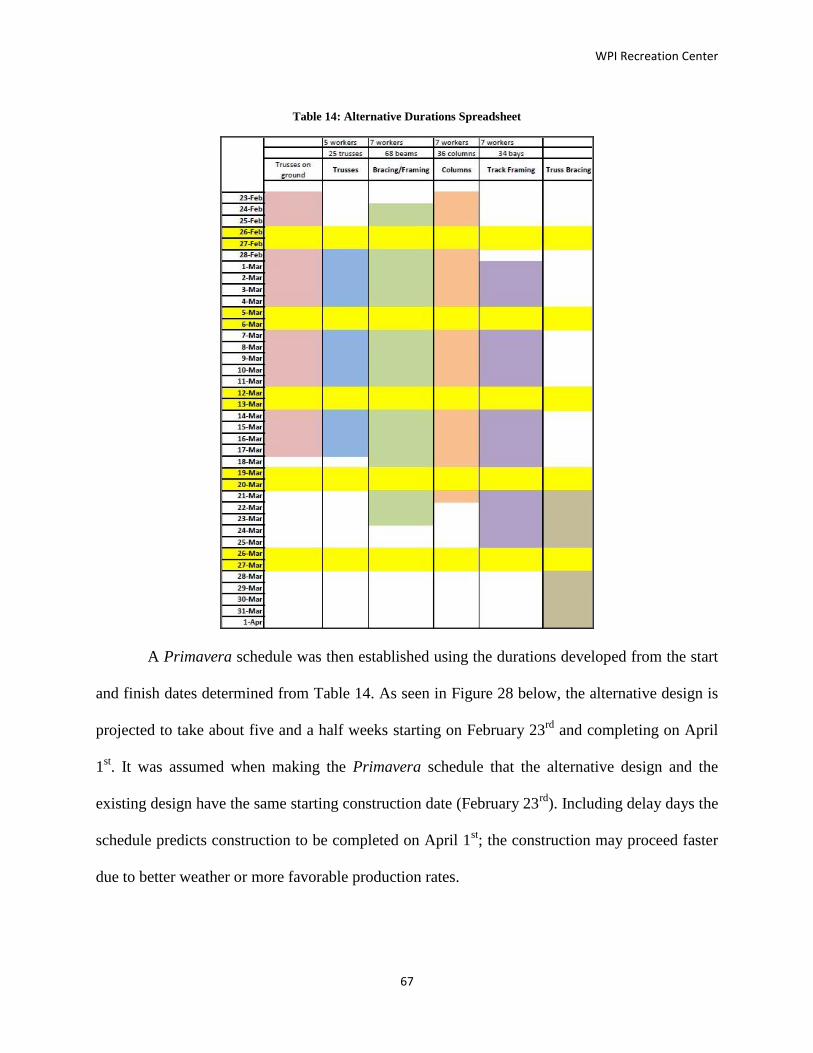
WPI Recreation Center
67
Table 14: Alternative Durations Spreadsheet
A Primavera schedule was then established using the durations developed from the start
and finish dates determined from Table 14. As seen in Figure 28 below, the alternative design is
projected to take about five and a half weeks starting on February 23rd
and completing on April
1st. It was assumed when making the Primavera schedule that the alternative design and the
existing design have the same starting construction date (February 23rd
). Including delay days the
schedule predicts construction to be completed on April 1st; the construction may proceed faster
due to better weather or more favorable production rates.

WPI Recreation Center
68
Figure 28: Alternative Schedule Primavera Screenshot
4.4 Creation of 4-D BIM for Alternate Design
The creation of the 4-D model followed the same “phasing” process that was followed in
Section 3.5: Creation of 4-D BIM. We again created four phases for the alternative design based
on the alternative schedule. The phases were created out of the model made by members of the
group, not based from the Cannon model as it was no longer the same design. We took the phase
snap-shots on the same dates as existing design, except for the last phase. Based on the schedule
analysis, it was projected that the alternative design could be completed about a week before the
existing if there are no delays. Even though this is unlikely, the last phase is shown on April 1st
in the assumption that everything would be perfect. We kept all other phases on the same date for
ease of comparison in the next chapter.
Table 15: Breakdown by Phase for Alternative Design
Breakdown by Phase
Phase
# Date %Complete Steel
Tonnage %Complete
1 3/7/2011 25% 21.05 11%
2 3/17/2011 50% 85.15 45%
3 3/27/2011 75% 146.4 77%
4 4/1/2011 100% 191.26 100%

WPI Recreation Center
69
Phase 1 is shown below for the alternative design on 3/7/2011. In Phase 1, one column
bay has been completed, along with some of the track framing on the Morgan side of the
building. In this Phase, 21.05 tons have been erected; that is 11% of the total steel.
Figure 29: Phase 1 Alternative Design
Below, Figure 30 shows Phase 2 on 3/17/2011. This phase shows significant progress
from the first phase. There is a total of 85.15 tons of steel erected; that is 45% of the total
tonnage of steel and 34% more steel erected than was in Phase 1.

WPI Recreation Center
70
Figure 30: Phase 2 of Alternative Design
Phase 3 for the alternative design is right on track work-wise with the schedule. Phase 3
shows the track at 75% complete schedule-wise and work-wise it is 77% complete. Figure 31
shows Phase 3 as it is seen in the Revit model.
Figure 31: Phase 3 of Alternative Design

WPI Recreation Center
71
The last phase or “New Construction” is the alternate track at completed. This phase
shows the final 27% of steel that had to be erected from Phase 3. The entire 191 tons of steel is
erected and shown in Figure 32.
Figure 32: Completed Alternate Track Design
This phase is shown on 4/1/2011. As previously mentioned, if no delays occur the
alternate design could take a total of five weeks to complete.

WPI Recreation Center
72
Chapter 5 - Evaluation/Analysis of Designs
Both designs were compared based on the evaluation and analysis of this project. This
chapter will compare the designs based on the structural design, the cost differences, the
schedule differences, and the differences found through the use of BIM.
5.1 Design Comparison
The main design differential between the two designs is the configuration of the
structural supports for the track due to the elimination of the hanging supports. Eliminating the
hanging supports caused an increase of weight on all portions of the track. Each component that
was altered by the removal of the hanging supports was accommodated for the additional weight.
The main differences in the straight portions of the track were the lengths of the end
beams to accommodate the revised framing, the creation of the cantilevers, and strengthening of
girders between the columns. Figure 33 represents Cannon’s configuration of the Football Side’s
straight portions which consists of hanging supports, end beams (which connect to the hanging
supports at each set of end beams, parallel to the columns), perpendicular girders and supporting
beams between each set of columns. The hanging supports were determined from the drawings
to be HSS7x7x0.5 vertical supports which run parallel to the columns. The end beams were
designed as simple beams and were configured to be W10x22 sections. Between each set of
hanging supports, there are two W10x22 end beams supporting the track. The perpendicular
girders span across each straight away and connect, connect each end beam to the columns or
column beams; they were specified to be W10x19 sections. A series of W14x22 beams span
between the columns and support the W10x19 girders.

WPI Recreation Center
73
Figure 33: Existing Revit Design Football Side
As previously stated throughout the project, the main alteration to the design was the
removal of the vertical hanging supports. A section of the alternative design is portrayed in
Figure 34 which represents the straight portions of the track along the Football Side of the
building; it is a revised version of Figure 33 for was of comparison. Most of the configuration is
the same from the previous design except for the lengthening of the end beams from 9’8” to
19’4”. This minimized the number of cantilevers in the design and the overall moment on the
columns. Since the end beams were lengthened, they pick up more dead and live load, and
consequently the member size increased from W10x22 to W12x14 sections. The perpendicular
girders that span the width of the track (the W10x19 sections in Figure 33) were converted into a
system of cantilevers (at the column lines) and simple beams (between the columns). The
cantilevers develop moments at the column faces from the various design loads for the track, and
so the member sizes were increased from the existing W10x19 to W18x35. The perpendicular
middle beams that were treated as simple beams did not carry much of a load because of the new
design, so they were calculated to be W10x22s. Finally, a small decrease in loading occurred in
the girders that span between the columns, and so their member size was reduced from W14x22
to W12x14. The section of the track along the football field is simplest portion because of the
limited factors associated with the design. The other sides, such as the Quad side, have

WPI Recreation Center
74
additional loadings which cause the scheme to be more complex. For example, the beams and
columns along the Quad side of the track must also support an adjacent floor slab. Investigation
into these other areas of the track can be referenced in Error! Reference source not found..
Figure 34: Alternative Revit Design Football Side
The four corners of the track can be classified into three sections: the Morgan side, the
Football/ Softball side, and Quad/ Softball side. The Morgan corners of the track are mirror
reflections of each other because they do not have additional factors affecting their design.
Figure 35 presents the existing design from the Morgan side of the track which includes hanging
supports.
Figure 35: Morgan Corner of Existing Design
Figure 36 represents the alternative design configuration of the Morgan side of the track.
Some of the aspects that have been altered from the existing design were the beam lengths of the

WPI Recreation Center
75
long middle beam and the member sizes of all of the beams. Specifically, the middle beam was
lengthened to minimize the cantilevers in the corner scenario, and the member sizes were all
changed because the loading scheme had changed due to the elimination of the hanging supports.
As mentioned before, Figure 36 is the simplest example of one of the four corners. The Football/
Softball corner and the Quad/ Softball have different configurations and can be reference in
Error! Reference source not found..
Figure 36: Morgan Corner of Alternative Design
The columns supporting the track remained the same size for every column surrounding
the track. This was the one structural element that was not changed between the existing design
and the alternative design. The existing column capacities were analyzed, and they were found
to be sufficient to support the alternative track, including the moment effects from the cantilever
beams.
These alterations to the design are only one component to the overall analysis of the
track. Aspects such as the project cost and schedule still need to be analyzed and incorporated to
understand which design has better components.

WPI Recreation Center
76
5.2 Cost Comparison
The two designs were compared based on the beam and girders, columns, and trusses.
The alternative design proved to be 0.67% more expensive than the existing design that was
created in this project. The beam and girders for the alternative design are about $6,000 more
expensive. This slight increase in price is due to the cantilever members in the alternative design.
Many of the beam sizes for the simple span beams decreased, but the cantilever member sizes
increased greatly in many cases versus their counterparts in the existing design, causing an
increase in price for the framing aspect of the design.
When the columns were analyzed, it was found that all of the columns in the existing
building could remain the same because they have sufficient capacity to support the new design,
including the combined effects of flexure and axial compression. A consideration of
constructability was also a part of the motivation to keep the columns the same size as for the
existing design. It was assumed that the existing column sizes were established to be convenient
to fabricate and erect: many of the columns throughout the affected area are the same or similar
in size. The trusses were also assumed to be adequate in strength because the hanger supports
were removed from the loading on the trusses. For this reason, the costs of both the columns and
the trusses remained the same. Below, Table 16 shows the comparison for the costs between
each aspect of the alternative and existing designs. The boxes highlighted in yellow show the
totals for each individual design.

WPI Recreation Center
77
Table 16: Cost Comparison of Existing and Alternative Design
Existing Design Alternative Design
Cost Per Group Cost Per Group
Framing Columns Trusses Framing Columns Trusses
$184,100 $174,200 $547,200 $190,000 $174,200 $547,200
Total $905,526.37 Total
$911,513.83
As noted before, it can be seen that the difference in price is simply from the beams and
girders. It is a difference of $5,987.46. Overall, that makes the alternative design .67% more
expensive. In the overall scheme of the project, this difference of about $6000 is practically
negligible as the total cost of the project is approaching $46.5 Million.
5.3 Schedule Comparison
While the manner in which the structural framing for the track supports the applied loads
and its physical appearance have changed dramatically, the expected process for installation of
the track and its supporting steel has not. Schedules of the existing and alternative design were
developed to reflect estimated durations and the sequence of completion. Below, in Figure 37
and Figure 38, are the Primavera schedules which compare the two different designs. The
designs followed similar sequences of installing approximately one column bay per day.
Figure 37: Existing Design Schedule
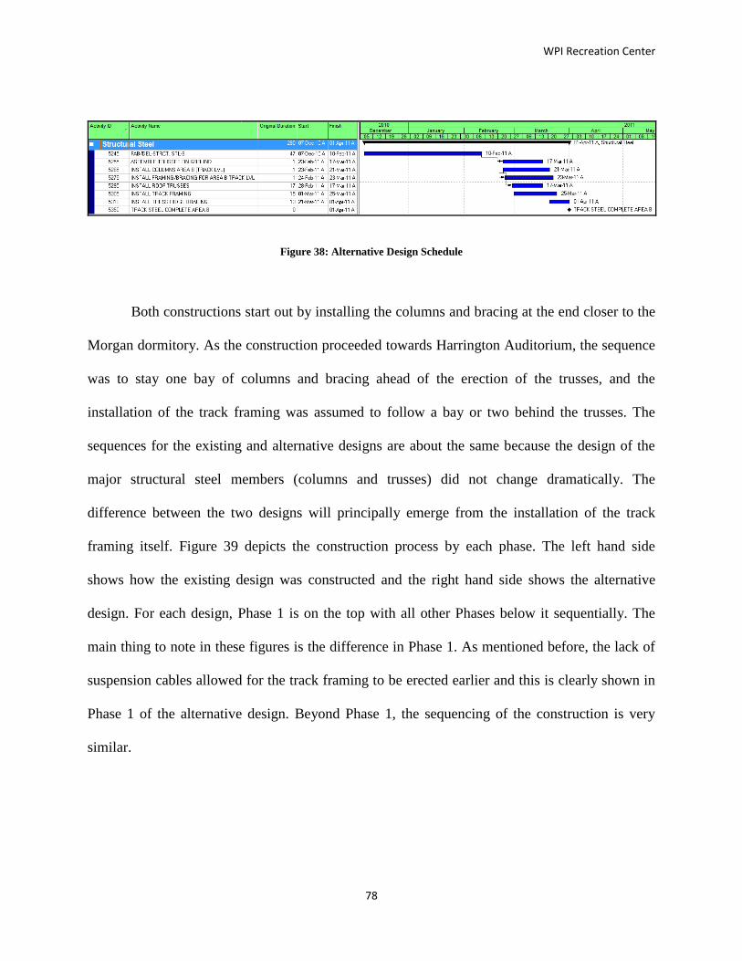
WPI Recreation Center
78
Figure 38: Alternative Design Schedule
Both constructions start out by installing the columns and bracing at the end closer to the
Morgan dormitory. As the construction proceeded towards Harrington Auditorium, the sequence
was to stay one bay of columns and bracing ahead of the erection of the trusses, and the
installation of the track framing was assumed to follow a bay or two behind the trusses. The
sequences for the existing and alternative designs are about the same because the design of the
major structural steel members (columns and trusses) did not change dramatically. The
difference between the two designs will principally emerge from the installation of the track
framing itself. Figure 39 depicts the construction process by each phase. The left hand side
shows how the existing design was constructed and the right hand side shows the alternative
design. For each design, Phase 1 is on the top with all other Phases below it sequentially. The
main thing to note in these figures is the difference in Phase 1. As mentioned before, the lack of
suspension cables allowed for the track framing to be erected earlier and this is clearly shown in
Phase 1 of the alternative design. Beyond Phase 1, the sequencing of the construction is very
similar.

WPI Recreation Center
79
Figure 39: Phase Comparisons from Revit
Because the suspended cables are being eliminated from the existing design, the erection
of the proposed alternative design should be a little faster for two or more reasons. First, the
alternative should be faster to erect because the workers will not need to take a lift up to the level
of the roof trusses to attach the cables. The second reason is because eliminating the cables will
make the design more uniform and repetitious. Without the cables, erecting the track framing
becomes the repetitive installation of beams, allowing the workers production to increase as they

WPI Recreation Center
80
do more. With these anticipated changes in the erection process it would be expected that the
alternative design would take a lot less time to install, but it does not. The reason it does not is
because the track framing cannot be installed until the columns, bracing, and trusses are
installed. For coordination purposes the track framing erection follows one or two column bays
behind the erection of the columns, bracing and trusses. This sequence of erection assures the
safety of the workers erecting the track framing so that no trusses are being flown in and erected
directly above where they are working. Therefore, the track framing cannot be installed any
faster than the trusses.
Both schedules were created with the same start date of February 23, 2011, and both
ended near the beginning of April. The alternative design’s completion date was projected at
April 1, 2011. The actual existing design’s completion date was April 6, 2011, which was
estimated to have been delayed a few days due to snow, and a couple other days due to reasons
not clear from looking at the time lapse photos. Because of the method used to project the
durations of the alternative design the estimated time intervals allow for several delays due to
unforeseen events. If the construction runs smoothly the alternative design could possibly be
installed a week or two faster than the existing design. But, because the new design does not
speed up the overall installation of the track significantly, the benefits of choosing the alternative
design because of schedule are not overwhelming. With the track being installed earlier there is a
chance that other trades such as plumbers and electricians could install there pipes and conduits
underneath the track earlier. This could in turn allow them to start earlier on other projects,
potentially shortening the entire project.

WPI Recreation Center
81
5.3.1 Phase Comparison through Revit
The other aspect of the schedule that could be compared through the Revit model was the
percent completed in each phase. Table 17 below shows the information for the existing design
on the left side and the alternative design on the right side of the table. The table shows the
percent complete for Phase 1 as slightly greater because of the additional erected steel that was
shown in Figure 39 of the previous section Table 17. Also, a final note to be made is that the
final phase in the alternative design was also assumed to be completed under perfect conditions
on 4/1/2011.
Table 17: % Complete by Tonnage and Schedule for Both Designs
Breakdown by Phase
Existing Design Alternate Design
Steel Date Phase# %Complete Date Steel
Tonnage %Complete Tonnage %Complete
20.49 7.50% 3/7/2011 1 25% 3/7/2011 21.05 11.00%
109.44 40% 3/17/2011 2 50% 3/17/2011 85.15 45%
179.82 66% 3/27/2011 3 75% 3/27/2011 146.4 77%
270.56 100% 4/6/2011 4 100% 4/1/2011 191.26 100%
The differences in the percentage complete for the other phases can be explained through
looking at the difference in total tonnage for the existing and alternate design. Because the total
tonnage is different, it causes the percentage complete of steel to be misleading. The percent
complete by phase appears to vary significantly between the two designs, even though the
figures and schedule show them to be more similar. The difference in these values can be
accounted for by many things. First, it could be caused by human error. The original phases were
made in the Revit model provided by Cannon. When creating these phases, the track construction
was isolated from the rest of the building by deleting those members and analytical lines that
were not considered relevant. Some of the analytical lines may have been missed, and

WPI Recreation Center
82
consequently were added to our schedule quantities. Another variance is due to including the
truss bracing in the schedules exported from the Cannon model. These brace members were not
addressed in the scope of the project and were not included when the alternative design was
modeled in Revit.
Overall, the Revit model supports the previous findings through the design, cost, and
schedule in determining that the alternative design does not have any significant advantages or
disadvantages in comparison to the existing design.
WPI Recreation Center
83
Chapter 6 – Conclusions & Recommendations
The focus of our results in this MQP was the comparative analysis between the existing
and alternative designs. The design, cost, and schedule were analyzed to make determinations
about each design against the other. The comparative analysis in this project was heavily
dependent on different software programs such as Revit, Robot, and Primavera. These three
programs were intended to help us create the design, cost estimate, and schedule for the alternate
track support structure. The main focus was on Revit and Robot, and the integration of these
programs into structural engineering and project management in a realistic project setting
allowed for the potential uses in these technologies to be realized. The heavy reliance on
software also put some constraints and difficulties on the project as well.
6.1 Recommendations Based on Comparisons
In creating an alternate design, the goal was to propose a structural solution that would
still meet the same needs that the original track design was intended to meet. The alternate
design was analyzed based on its structural capability, its cost, and its schedule. It was found that
the alternate design was almost equivalent to the existing design in every way.
Structurally, the alternate option was designed to hold the same loads as the existing and
serve the same purpose as an indoor walking/jogging track. Through the cost analysis, the
alternate design was 0.67% more expensive than the system currently in place. Schedule-wise,
the alternate design has the potential to finish 5 days sooner; this includes weather delays likely
during the winter months and other unexpected happenings. By accounting for unexpected
delays in the alternative schedule it allows for a chance that the construction could finish a few
days earlier in the case of no delays.
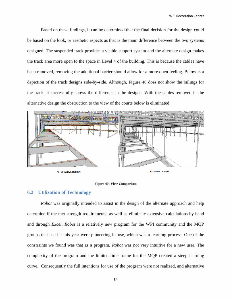
WPI Recreation Center
84
Based on these findings, it can be determined that the final decision for the design could
be based on the look, or aesthetic aspects as that is the main difference between the two systems
designed. The suspended track provides a visible support system and the alternate design makes
the track area more open to the space in Level 4 of the building. This is because the cables have
been removed, removing the additional barrier should allow for a more open feeling. Below is a
depiction of the track designs side-by-side. Although, Figure 40 does not show the railings for
the track, it successfully shows the difference in the designs. With the cables removed in the
alternative design the obstruction to the view of the courts below is eliminated.
Figure 40: View Comparison
6.2 Utilization of Technology
Robot was originally intended to assist in the design of the alternate approach and help
determine if the met strength requirements, as well as eliminate extensive calculations by hand
and through Excel. Robot is a relatively new program for the WPI community and the MQP
groups that used it this year were pioneering its use, which was a learning process. One of the
constraints we found was that as a program, Robot was not very intuitive for a new user. The
complexity of the program and the limited time frame for the MQP created a steep learning
curve. Consequently the full intentions for use of the program were not realized, and alternative

WPI Recreation Center
85
strategies were adopted to complete the structural design effort. For example, a separate plan
utilizing hand calculations and Excel was put into place.
Revit was used as a means of creating a 4-D model for the project and researching the
potential uses of Building Information Modeling (BIM). In the scope of this MQP, Revit was
able to create a 4-D model by incorporating schedule items through the use of phasing in the
program. In the future, BIM could be used to create a 5-D model by also incorporating cost into
the model. This would allow for even more information to be available to the building users in
the model. A 5-D model is not as common in construction as 4-D, but has potential to gain
significant popularity.
In the process of creating and comparing the designs, cost estimates, and schedules, it
was easy to see the potential for technology to play an even larger role in engineering and
construction. In future MQP’s the use of Robot can be built upon and used more effectively to
take advantage of the great possibilities that the program has. Also, the exploration of creating a
5-D model would be interesting to study and to explore how that advancing technology can be
integrated better decision making into the engineering and construction areas of a project.

WPI Recreation Center
86
Chapter 7 - References
Allen, Richard K. (1995). The Estimation of Construction Contract Liquidated Damages.
Retrieved 10/2, 2012 from http://library.findlaw.com/1995/Jan/1/129415.html.
Autodesk. (2011). Robot Structural Analysis Professional Brochure. Retrieved 10/2, 2011 from
http://images.autodesk.com/adsk/files/autodesk_robot_structural_analysis_professional_2
012_brochure.pdf
Autodesk. (2011). User’s Guide. Retrieved 2/1, 2012 from
http://images.autodesk.com/adsk/files/revit_architecture_2011_user_guide_en.pdf
Autodesk. (2007). Revit Structure and BIM. Retrieved 10/2, 2011 from
http://images.autodesk.com/adsk/files/revit_structure_and_bim.pdf
Bright Hub. (2011). The Top 5 Project Scheduling Software Programs. Retrieved 10/3, 2012
from http://www.brighthub.com/office/project-management/articles/2492.aspx
Cannon Design. Recreation Center Structural Plans. Structural Design Plans. Boston, MA:
Cannon Design, 2011.
Charney, Finley A. Seismic Loads: Guide to the Seismic Load Provisions of ASCE 7-05. Reston,
VA. 2010: American Society of Civil Engineers.
Delahay & Mehta. Guide to the Use of the Wind Load Provisions of ASCE 7-02. Reston, VA.
2004: American Society of Civil Engineers.
Department of Energy. Appendix B: Energy and Construction Cost Estimates. Retrieved 2/1,
2012 from http://www1.eere.energy.gov/femp/pdfs/buscase_appendixb.pdf.
Engineering News Record (ENR). (2011, August 15). Construction Economics. ENR.

WPI Recreation Center
87
Farah, Toni. (2005). Review of Current Estimating Capabilities of the 3D Building Information
Model Software to Support Design for Production/Construction. Worcester Polytechnic
Institute.
Fournier, Kristopher, et al. (2011). WPI Recreation Center: Construction Management and
Alternative Design Analysis. Worcester Polytechnic Institute.
Gilbane. (2011). Primavera Schedule Files. Worcester, MA: Gilbane.
Glaeser, et. al. (2004). Why Is Manhattan So Expensive? Regulation and the Rise in House
Prices. Harvard University. Retrieved 2/2, 2012 from
http://www.economics.harvard.edu/faculty/glaeser/files/Manhattan.pdf
Oberlender, G. (2000). Project Management for Engineering and Construction 2nd
Edition.
McGraw Hill.
Oracle. (2011). Oracle and Primavera. Retrieved 10/5, 2011 from
http://www.oracle.com/us/corporate/Acquisitions/primavera/index.html?origref=http://ww
w.google.com.au/search?gcx=c&sourceid=chrome&ie=UTF-8&q=primavera
Oracle. (2011). Oracle’s Primavera P6 Enterprise PPM Release 8.1. Retrieved 10/5, 2011 from
http://www.oracle.com/us/products/applications/primavera/primavera-p6-v8-release-
174720.html
RFF Flow. (2011). PERT, CPM, and WBS Charts. Retrieved 10/5, 2011 from
http://www.rff.com/sample_pert.htm
RS Means Company, Inc. (2012). Retrieved 1/27, 2012 from
http://rsmeans.reedconstructiondata.com/Reference-Books.aspx
RS Means Company, Inc. RS Means Heavy Construction Cost Data. Kingston, MA: RS Means
Company, Inc.

WPI Recreation Center
88
Salazar, Guillermo. (2011) Personal communication, October 2011.
Schinler, Dan, and Erik Nelson. Dec. 2008. "BIM and the Structural Engineering Community."
Structural Engineering Magazine. Retrieved 10/2, 2011 from
<http://www.structuremag.org/article.aspx?articleID=810>.
Turgeon, Walter. (2012), Personal communication, February 2012.

WPI Recreation Center
89