Embed Size (px)
Citation preview
www.KleinschmidtGroup.com
POTENTIAL FAILURE OF WEST GRAND LAKE DAM DIAGNOSING
AND AVERTING AN IMMINENT FAILURE
MR. DAVID B. NASH, P.E., KLEINSCHMIDT ASSOCIATES, PITTSFIELD, ME, USA
ABSTRACT
The West Grand Lake Dam is located in eastern Maine on the west branch of the St. Croix River.
The dam is approximately 487 feet in length, comprised of a 106 feet long concrete and rock-
filled timber crib gate structure bordered on either side by an earth embankment. In 2003, the
dam was subject to a Potential Failure Modes Analysis (PFMA) to conform to federal safety
standards.
Out of several potential failure modes identified, the PFMA team considered the possibility for
failure of the upstream cutoff wall leading to subsurface flow as the most severe candidate failure
mode. If this process were occurring, material could be removed from below the dam with little
to no indication visible to an observer.
On August 14, 2003, a potential failure situation developed at the West Grand Lake Dam. At that
time, a significant flow was observed bypassing the timber gate structure and a silt plume was
observed downstream of the dam, indicating erosion of foundation and ballast material from
within the timber crib structure. Emergency measures were taken to prevent undermining and
failure of the structure. At that time, a plan for permanent emergency repairs was conceived and
implementation began immediately.
The permanent repairs included installation of a new cutoff wall, reinforcement of the gate piers,
and placement of a new concrete apron. These modifications have effectively eliminated the
possibility for this mechanism to develop in the future. This paper is a chronological description
of the near failure of this dam, including the acknowledgement of the potential mechanism,
diagnosis of the developing mechanism, and the permanent construction remedy devised to avert
the failure.
INTRODUCTION
Prior to the potential failure and subsequent modifications, the West Grand Lake dam consisted
of an earth embankment and a timber crib gate structure set behind a concrete trash rack structure
and a fishway bordering the right abutment. Full pond in West Grand Lake is at elevation
301.43', and the available head of approximately 8.5 ft represents storage capacity of 160,900
acre-feet. The gate structure had five hand-operated wooden gates equipped with ratchet-type
hoists. Integral with the timber apron upstream of the gates was a vertical timber cut-off wall.
The existing project drawings indicated that the cut-off wall was installed to the naturally
deposited alluvial material. The purpose of this cut-off wall was to prevent potentially damaging
underflow.
POTENTIAL FAILURE OF WEST GRAND LAKE DAM DIAGNOSING
AND AVERTING AN IMMINENT FAILURE
MR. DAVID B. NASH, P.E., KLEINSCHMIDT ASSOCIATES, PITTSFIELD, ME, USA
www.KleinschmidtGroup.com 2
Recent dam break analyses for the structure indicated that a dam failure during both sunny day
and Probable Maximum Flood (PMF) conditions would potentially inundate both the State of
Maine fish hatchery facility, located approximately 0.2 miles downstream of the dam, and a few
residential structures along Grand Lake Stream. Analysis determined the incremental inundation
of the fish hatchery starts at a discharge rate of approximately 3,000 cfs and increases to 5.8 ft at
the PMF condition. Therefore, the Inflow Design Flood (IDF) for the West Grand Lake Dam was
determined to be the PMF. The project is rated as a significant hazard dam.
INITIAL RESPONSE
On August 14, 2003 at 9:00 a.m. Kleinschmidt Associates, the independent consultant for the
fifth Part 12 report and part of the PFMA core team, was notified of excessive flow (18 inch
depth across the width of 9 ft) passing through the number five gate bay at the dam. This flow
was occurring with the gate closed. Kleinschmidt was notified that some of the wood planking
was missing downstream of the gate and water was boiling up through the apron and from the
walls of the crib piers. It quickly became obvious that this was not a simple problem, rather
much worse, a dam failure in progress. Emergency protocols were initiated.
By 1:30 p.m. Cianbro Corporation, working locally at the nearby mill, was mobilized at the site
with plastic sheets, small sandbags, bulk grain bags, a mini excavator to fill the bags, and a truck
crane to lower them into place. Instruction was given to attempt to locate the source of the
underflow on the upstream side of the gates by use of a pick pole with a streamer (ribbon)
attached to the end. Particular attention was to be directed to the location of the upstream
vertical cut-off wall and the timber apron.
During the course of this inspection, several “hot spots” were detected along the cut-off location
as well as along an existing concrete training wall between the gate structure and fishway. Sheet
plastic was submerged with small sand bags over the suspect areas. Additionally, the contractor
placed one cubic yard sized bulk grain bags on the areas of most concern.

POTENTIAL FAILURE OF WEST GRAND LAKE DAM DIAGNOSING
AND AVERTING AN IMMINENT FAILURE
MR. DAVID B. NASH, P.E., KLEINSCHMIDT ASSOCIATES, PITTSFIELD, ME, USA
www.KleinschmidtGroup.com 3
SANDBAGS FILLING VOIDS UPSTREAM OF GATE APRON
The temporary measures were effective at reducing the flow to a more tolerable level by 5:00
p.m., however nine inches depth of flow was still passing through the gate area. The conclusion
was that the project was in an emergency condition. The Emergency Action Plan (EAP)
notification flow chart was partially enacted, regional agencies were notified and informed that
investigation was underway, and a security guard was put on 24-hour alert.
The emergency response team, consisting of a Domtar representative, Kleinschmidt Associates,
and Cianbro Corporation, met early on the morning of August 15. A plan was conceived by 8:00
a.m. similar in concept to one Kleinschmidt Associates had used in 2002 to mitigate a similar
type of failure of a timber structure. By noon that same day, the concept was faxed to regional
agencies and a conference call took place early in the afternoon. To add to the excitement, there
was a major power failure on the east coast going on at the same time adding to the
communication challenge.
By the morning of August 16 the regional dam inspector, Mr. Harold Kamara, was on site to
review the status of the situation and the temporary measures installed. The contractor was in the
process of mobilizing a larger crane and steel sheetpile to be used as the cofferdam. By Monday,
August 18, the contractor began driving steel sheetpile for the first phase of the planned
cofferdam.
POTENTIAL FAILURE OF WEST GRAND LAKE DAM DIAGNOSING
AND AVERTING AN IMMINENT FAILURE
MR. DAVID B. NASH, P.E., KLEINSCHMIDT ASSOCIATES, PITTSFIELD, ME, USA
www.KleinschmidtGroup.com 4
DESIGN
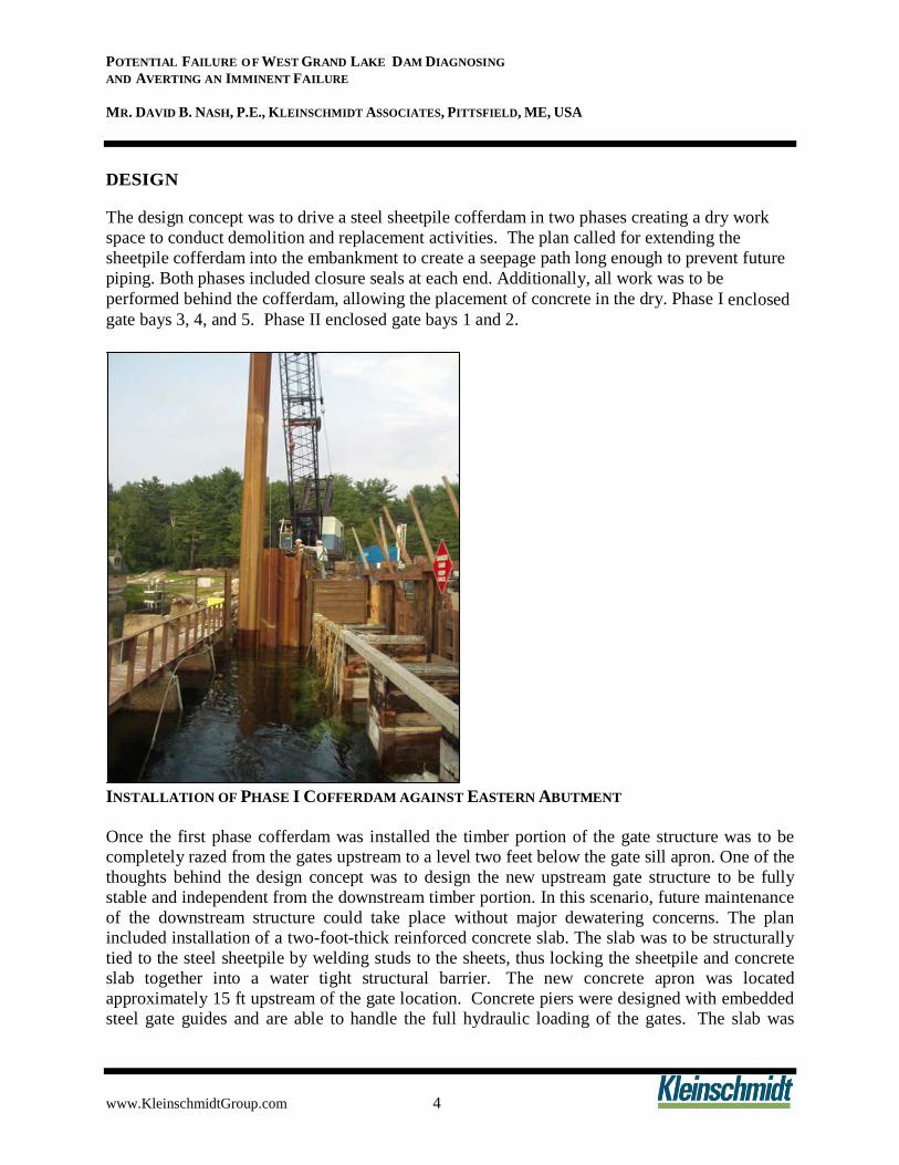
The design concept was to drive a steel sheetpile cofferdam in two phases creating a dry work
space to conduct demolition and replacement activities. The plan called for extending the
sheetpile cofferdam into the embankment to create a seepage path long enough to prevent future
piping. Both phases included closure seals at each end. Additionally, all work was to be
performed behind the cofferdam, allowing the placement of concrete in the dry. Phase I enclosed
gate bays 3, 4, and 5. Phase II enclosed gate bays 1 and 2.
INSTALLATION OF PHASE I COFFERDAM AGAINST EASTERN ABUTMENT
Once the first phase cofferdam was installed the timber portion of the gate structure was to be
completely razed from the gates upstream to a level two feet below the gate sill apron. One of the
thoughts behind the design concept was to design the new upstream gate structure to be fully
stable and independent from the downstream timber portion. In this scenario, future maintenance
of the downstream structure could take place without major dewatering concerns. The plan
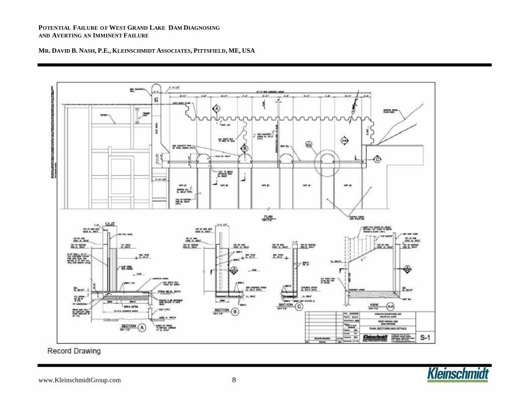
included installation of a two-foot-thick reinforced concrete slab. The slab was to be structurally
tied to the steel sheetpile by welding studs to the sheets, thus locking the sheetpile and concrete
slab together into a water tight structural barrier. The new concrete apron was located
approximately 15 ft upstream of the gate location. Concrete piers were designed with embedded
steel gate guides and are able to handle the full hydraulic loading of the gates. The slab was

POTENTIAL FAILURE OF WEST GRAND LAKE DAM DIAGNOSING
AND AVERTING AN IMMINENT FAILURE
MR. DAVID B. NASH, P.E., KLEINSCHMIDT ASSOCIATES, PITTSFIELD, ME, USA
www.KleinschmidtGroup.com 5
designed to take full hydraulic loading and the load transferred from the piers and gates without
any buttressing affect from the downstream wood crib piers.
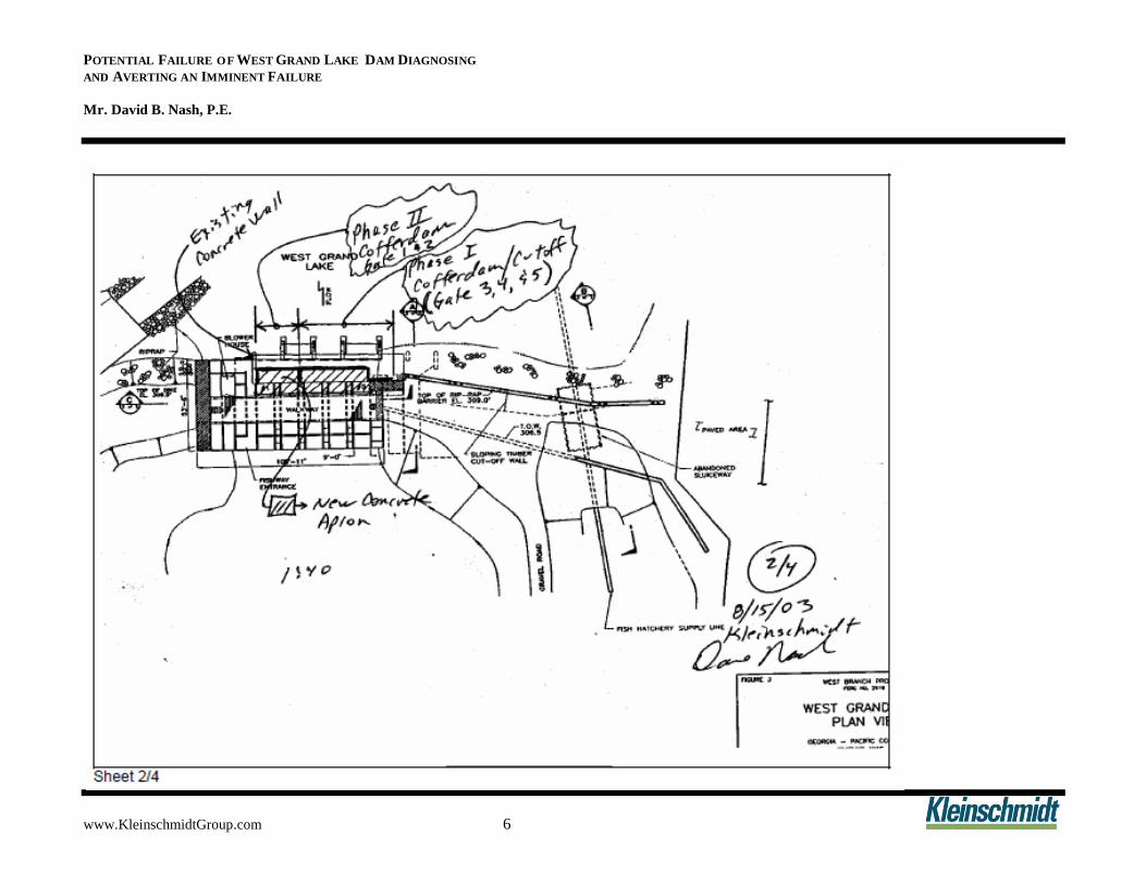
Once the Phase I cofferdam was installed and the flow could be transferred to the new gate
structure, the Phase II cofferdam was installed and the gate structure razed and then rebuilt. All
this work both in mobilization and design was done under emergency conditions and, as such,
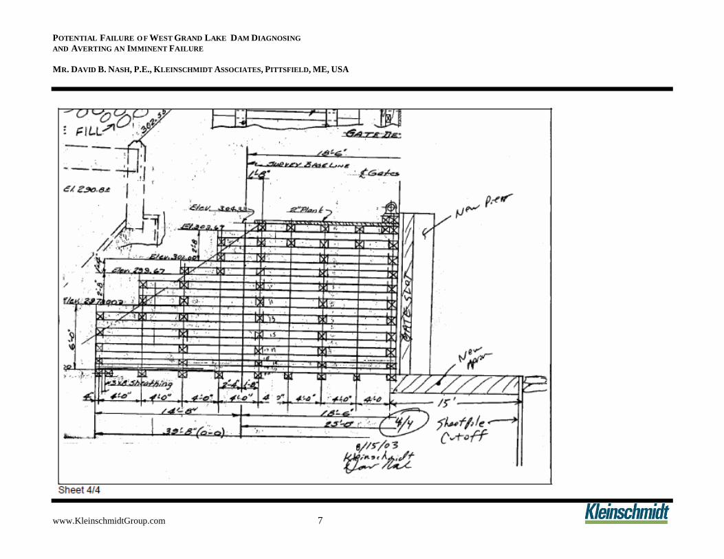
any method to expedite review, approval and construction was employed. For example, as you
can see from sheets 2/4 and 4/4, hand markups of existing plans were used to transmit the design
concept.
The sketches were developed one day after the event and faxed to the team for discussion. The
design concept never changed from the original concept. Other than details and CAD drafting,
you will see from the drawing developed there is not much difference between the conceptual
and final product.
POTENTIAL FAILURE OF WEST GRAND LAKE DAM DIAGNOSING
AND AVERTING AN IMMINENT FAILURE
Mr. David B. Nash, P.E.
www.KleinschmidtGroup.com 6
POTENTIAL FAILURE OF WEST GRAND LAKE DAM DIAGNOSING
AND AVERTING AN IMMINENT FAILURE
MR. DAVID B. NASH, P.E., KLEINSCHMIDT ASSOCIATES, PITTSFIELD, ME, USA
www.KleinschmidtGroup.com 7
POTENTIAL FAILURE OF WEST GRAND LAKE DAM DIAGNOSING
AND AVERTING AN IMMINENT FAILURE
MR. DAVID B. NASH, P.E., KLEINSCHMIDT ASSOCIATES, PITTSFIELD, ME, USA
www.KleinschmidtGroup.com 8
POTENTIAL FAILURE OF WEST GRAND LAKE DAM DIAGNOSING
AND AVERTING AN IMMINENT FAILURE
Mr. David B. Nash, P.E.
www.KleinschmidtGroup.com 9
This design concept had the unique benefit as the effectiveness of the water tightness could be
tested before committing to it. By using a steel sheetpile cofferdam with sheets driven to refusal,
it provided a good chance to seal the structure. It was anticipated that the real test would occur
when the coffer was dewatered, as any trouble spots such as underflow or end run flow would be
detected. The plan also required casting the concrete directly against the sheetpile and then
cutting the steel sheets flush with the concrete apron, which assured that the integrity of the
cutoff structure was maintained.
CONSTRUCTION
The project construction activities began almost immediately due to the emergency nature of the potential failure of the dam. Cianbro Corporation is credited with initiating work immediately. While on site Saturday discussing the plan and pace that had been started with Mr. Harold Kamara, Cianbro was already mobilizing a larger crane and steel sheetpile for the cofferdam, approximately two days from the onset of the problem. In fact, Cianbro Corporation was designing the details of the cofferdam and Kleinschmidt Associates was reviewing the design at
the times the sheets were being driven on Monday the 18th
.
The Phase I cofferdam was installed without major incident or changes required. The original
plan called for flat sheets to be driven against the timber crib abutment for a distance of fifteen
feet. As a result of difficulty in driving the sheets, they were flared away from the abutment and
extended into the embankment. This realignment allowed for the sheets to be driven, providing a
continuous cutoff on the east embankment. Once the cofferdam was dewatered, only minimal
seepage was observed in the area providing assurance of an effective seal. Upon dewatering the
coffer, it became apparent where some of the problems had developed. The vertical timber
cutoff wall was very shallow and did not penetrate the alluvial material. It appeared the original
construction only went down to the sub-grade and was built from a level granular surface up.
Additionally, many areas between the planking had significant water wear from past leakage. It
was possible to raze the entire crib apron and gate piers without incident. There was a
considerable amount of leakage end running from the cofferdam closure at the west end, but this
situation was adequately controlled for the Phase I work. A layer of stone was placed as a
subgrade of the slab prior to placing plastic sheeting and subsequent reinforcement. Phase I was
completed, including the proposed concrete apron and piers. The team felt confident that the gate
five area had been replaced and the leakage was well under control.
Work proceeded on to the Phase II cofferdam by putting in a steel diaphragm wall and
transferring flow to the new gate four and five area. Two difficulties developed in the Phase II
coffer, the first being interlocking the sheets to the phase one coffer and sealing at the fishway
side. This was resolved by installing a temporary gate in bay three, pulling the interlocking sheet
and driving new sheets. The second area was much more challenging as there appeared to be a
hole under the existing concrete wall. A number of sand bags were placed in the area with
minimal success at reducing the leakage to an acceptable level. An alternate cofferdam closure
plan was subsequently developed. This alternative consisted of entirely enclosing the gate
structure and fishway within the cofferdam. This was one of the best decisions the team made.
POTENTIAL FAILURE OF WEST GRAND LAKE DAM DIAGNOSING
AND AVERTING AN IMMINENT FAILURE
MR. DAVID B. NASH, P.E., KLEINSCHMIDT ASSOCIATES, PITTSFIELD, ME, USA
www.KleinschmidtGroup.com 10
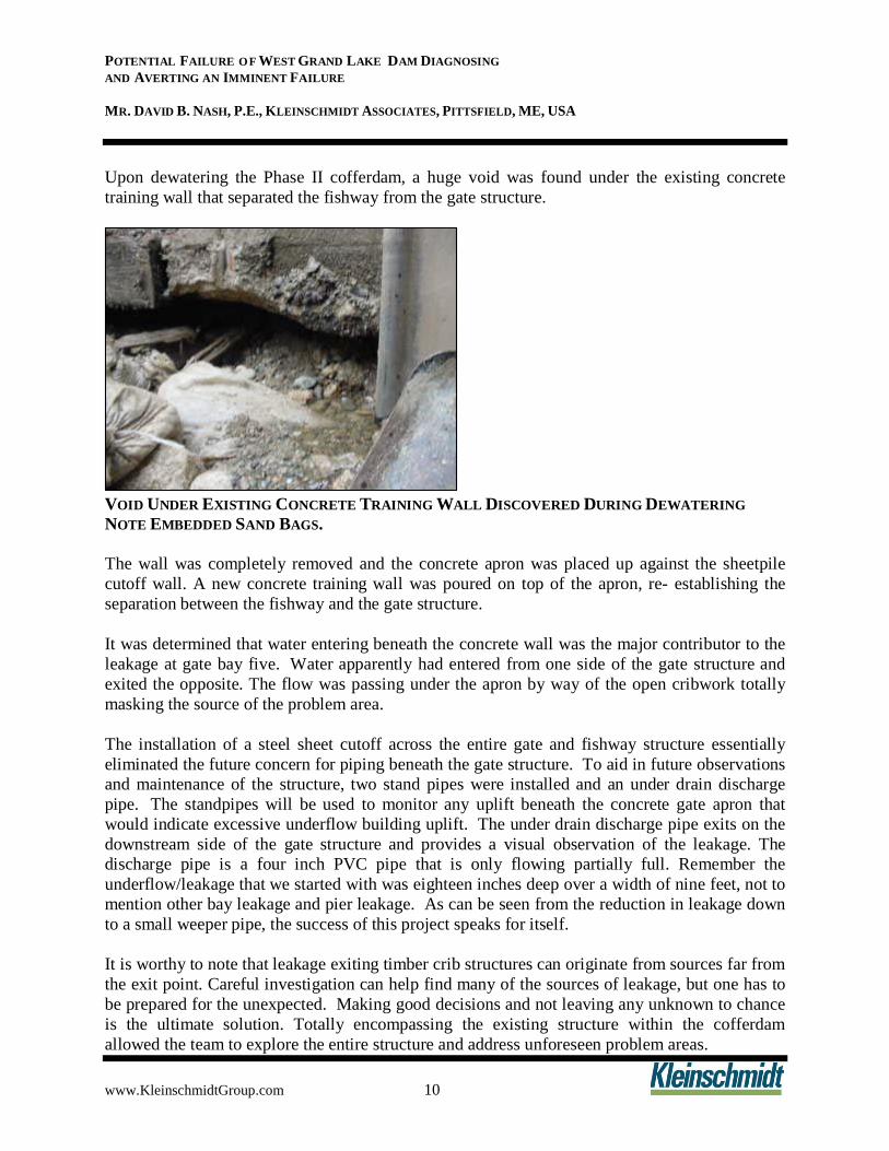
Upon dewatering the Phase II cofferdam, a huge void was found under the existing concrete
training wall that separated the fishway from the gate structure.
VOID UNDER EXISTING CONCRETE TRAINING WALL DISCOVERED DURING DEWATERING
NOTE EMBEDDED SAND BAGS.
The wall was completely removed and the concrete apron was placed up against the sheetpile
cutoff wall. A new concrete training wall was poured on top of the apron, re- establishing the
separation between the fishway and the gate structure.
It was determined that water entering beneath the concrete wall was the major contributor to the
leakage at gate bay five. Water apparently had entered from one side of the gate structure and
exited the opposite. The flow was passing under the apron by way of the open cribwork totally
masking the source of the problem area.
The installation of a steel sheet cutoff across the entire gate and fishway structure essentially
eliminated the future concern for piping beneath the gate structure. To aid in future observations
and maintenance of the structure, two stand pipes were installed and an under drain discharge
pipe. The standpipes will be used to monitor any uplift beneath the concrete gate apron that
would indicate excessive underflow building uplift. The under drain discharge pipe exits on the
downstream side of the gate structure and provides a visual observation of the leakage. The
discharge pipe is a four inch PVC pipe that is only flowing partially full. Remember the
underflow/leakage that we started with was eighteen inches deep over a width of nine feet, not to
mention other bay leakage and pier leakage. As can be seen from the reduction in leakage down
to a small weeper pipe, the success of this project speaks for itself.
It is worthy to note that leakage exiting timber crib structures can originate from sources far from
the exit point. Careful investigation can help find many of the sources of leakage, but one has to
be prepared for the unexpected. Making good decisions and not leaving any unknown to chance
is the ultimate solution. Totally encompassing the existing structure within the cofferdam
allowed the team to explore the entire structure and address unforeseen problem areas.

POTENTIAL FAILURE OF WEST GRAND LAKE DAM DIAGNOSING
AND AVERTING AN IMMINENT FAILURE
MR. DAVID B. NASH, P.E., KLEINSCHMIDT ASSOCIATES, PITTSFIELD, ME, USA
www.KleinschmidtGroup.com 11
CONCLUSIONS
It would be an understatement to say that the success of the design of this project under
emergency conditions was a team effort. Some examples of team work resulted in the owner,
Domtar Industries, under the direction of Mr. Tim Lowe, on the very next day after the
development of the emergency, accepting the situation and giving the go ahead for the design
concept and construction. The efforts of Mr. Steve Strout of the owners staff for coordination of
all aspects of the project and review of the design details and enhancing the design. Also, the
PFMA facilitator, Mr. Bruce Brand, reviewed the design concept and details on August 22, 2003,
after only receiving the design on August 18. Mr. Brand performed a structural analysis and
made suggestions as to areas of the slab that may need additional reinforcement. His comments
were directly applied to the constructed project.
Mr. Eugene Gall and his staff reviewed the design and construction plan and encouraged the
team with positive feedback. Additionally, Mr. Harold Kamara was on site on Saturday, August
16 to conduct an assessment of the situation and relay his findings back to New York. The
contractor, Cianbro Corporation, brought the equipment manpower and experience to this
dynamic team.
The implementation of the PFMA process was very timely on this project and correctly
identified a significant potential failure mode that was nearly tested. Timber crib structures all
leak, but there comes a point that certain indicators become tell-tale signs of developing
problems, such as excessive leakage and unexplained settlements. Emergency response teams
with qualified team members given decision making power result in very successful projects.
Even under emergency situations, one need not panic and positive environmental measures can
be undertaken.
COMPLETED PROJECT
POTENTIAL FAILURE OF WEST GRAND LAKE DAM DIAGNOSING
AND AVERTING AN IMMINENT FAILURE
MR. DAVID B. NASH, P.E., KLEINSCHMIDT ASSOCIATES, PITTSFIELD, ME, USA
www.KleinschmidtGroup.com 12
ACKNOWLEDGEMENTS
The authors would like to acknowledge that without a powerful team with the ability to make
decisions, this dam very well could have failed with significant social environmental fallout. It is
not possible to recognize all the individuals who had an impact to the success of this project
without inadvertently omitting some. However, had it not been for Domtar Industries willing to
do what was right, federal agencies expediting approval, Kleinschmidt Associates having the
experience and resources to complete the design, and Cianbro Corporation, a highly respected
and capable contractor, this could have been a very different outcome.