Embed Size (px)
Citation preview
________________________________________________
3213 Eastlake Ave E, Ste B
Seattle, WA 98102
Tel (206) 262-0370
Fax (206) 262-0374
Geotechnical & Earthquake
Engineering Consultants
February 1, 2018
File No. 18-007
Mr. Timothy Linehan
Monte Cristo Square LLC
9038 15th Avenue NW
Seattle, WA 98117
Subject: Subsurface Condition Characterization
12303 - 15th Avenue NE
Seattle, Washington
Dear Mr. Linehan,
As requested, PanGEO has completed a subsurface condition characterization for the proposed
development located at 12303 - 15th Avenue NE in Seattle, Washington. This study was
performed in general accordance with our mutually agreed scope of work outlined in our
proposal dated January 6, 2018 which was subsequently authorized by you on January 11, 2018.
Our service scope included reviewing readily available geologic data, conducting a site
reconnaissance, and drilling three test borings to evaluate the subsurface conditions at the site.
SITE AND PROJECT DESCRIPTION
The subject site consists of two parcels, 12303 and 12309 15th Avenue NE in Seattle,
Washington (see Figure 1). The combined site is roughly rectangular in shape and has a total
area of about 15,622 square feet. It is bordered to the east by 15th Avenue NE, to the south by NE
123rd Street, to the west by an existing single-family residence, and to the north by an apartment
building. The site is currently occupied by three one-story buildings. Based on review of the
topographic survey maps and our observations, the site grade gently slopes down from east to
west with a total elevation difference of about 5 feet across the site.
Mr. Timothy Linehan
Proposed Development: 12303 15th Avenue NE
February 1, 2018
18-007 12303 15th Ave NE Rpt PanGEO, Inc. Page 2
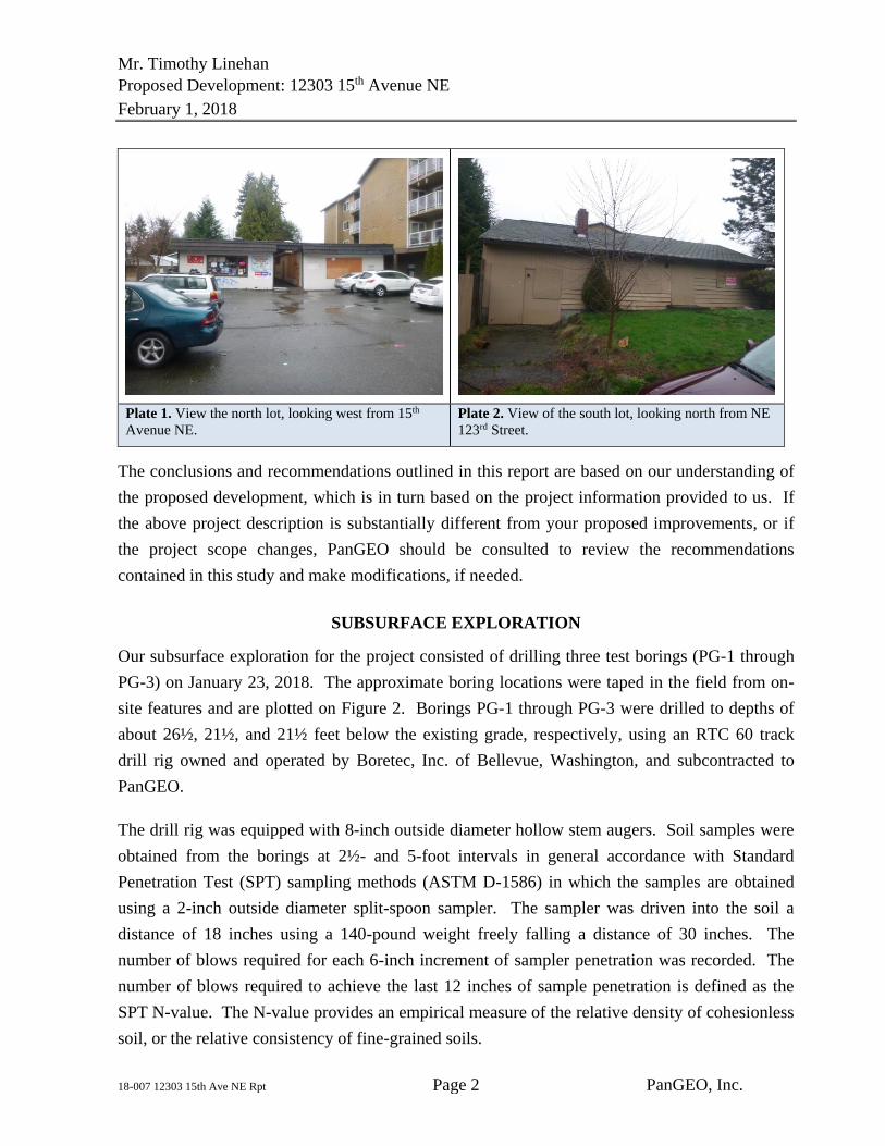
Plate 1. View the north lot, looking west from 15th
Avenue NE. Plate 2. View of the south lot, looking north from NE
123rd Street.
The conclusions and recommendations outlined in this report are based on our understanding of
the proposed development, which is in turn based on the project information provided to us. If
the above project description is substantially different from your proposed improvements, or if
the project scope changes, PanGEO should be consulted to review the recommendations
contained in this study and make modifications, if needed.
SUBSURFACE EXPLORATION
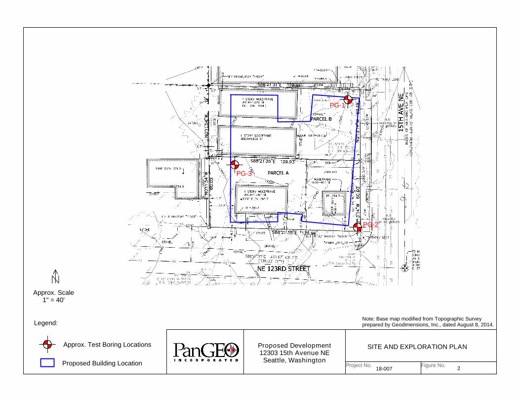
Our subsurface exploration for the project consisted of drilling three test borings (PG-1 through
PG-3) on January 23, 2018. The approximate boring locations were taped in the field from on-
site features and are plotted on Figure 2. Borings PG-1 through PG-3 were drilled to depths of
about 26½, 21½, and 21½ feet below the existing grade, respectively, using an RTC 60 track
drill rig owned and operated by Boretec, Inc. of Bellevue, Washington, and subcontracted to
PanGEO.
The drill rig was equipped with 8-inch outside diameter hollow stem augers. Soil samples were
obtained from the borings at 2½- and 5-foot intervals in general accordance with Standard
Penetration Test (SPT) sampling methods (ASTM D-1586) in which the samples are obtained
using a 2-inch outside diameter split-spoon sampler. The sampler was driven into the soil a
distance of 18 inches using a 140-pound weight freely falling a distance of 30 inches. The
number of blows required for each 6-inch increment of sampler penetration was recorded. The
number of blows required to achieve the last 12 inches of sample penetration is defined as the
SPT N-value. The N-value provides an empirical measure of the relative density of cohesionless
soil, or the relative consistency of fine-grained soils.
Mr. Timothy Linehan
Proposed Development: 12303 15th Avenue NE
February 1, 2018
18-007 12303 15th Ave NE Rpt PanGEO, Inc. Page 3
A geologist from PanGEO was present during the field exploration to observe the drilling, assist
in sampling, and to describe and document the soil samples obtained from the borings. The soil
samples were described and field classified in general accordance with the symbols and terms
outlined in Figure A-1 of Appendix A, and the summary boring logs are included as Figures A-2
through A-4.
SITE GEOLOGY
Based on review of The Geologic Map of Seattle – a Progress Report (Troost, et al., 2005), the
surficial geologic unit mapped in the vicinity of the subject site is Advance Outwash (Map Unit
Qva). Advance Outwash deposits are described by Troost, et al. as moderately- to well-sorted,
slightly oxidized sand and gravel that had been overridden by glacial ice. This unit is typically
dense.
SUBSURFACE CONDITIONS
SOIL
The soils encountered in our exploration appear to be generally consistent with the mapped
geologic unite at the site. The borings generally encountered a layer of fill overlying medium
dense to very dense, gray-brown, sand with trace gravel (Advance Outwash).
The following is a brief description of the soils encountered in the test borings drilled at the site.
Please refer to the summary test boring logs (Appendix A) for additional details.
UNIT 1 – Fill: We encountered about 3½ and 3 feet of fill in PG-1 and PG-2,
respectively. The fill consisted of loose, brown and gray, sand with silt and gravel, and
occasional rootlets. Fill was not encountered in PG-3.
UNIT 2 – Advance Outwash: Below the fill in PG-1 and PG-3, and topsoil in PG-3, we
encountered medium dense to very dense, sand with trace silt and gravel that we interpret
to be the mapped Advance Outwash deposits. The Advance Outwash was encountered to
the maximum exploration depths at about 21½ and 26½ feet below the existing grade.
The upper 4 to 6 feet of this unit is weathered.
It should be noted that our descriptions of subsurface conditions are based on the conditions
encountered at the time of our exploration. Soil conditions between our exploration locations
will vary from those encountered. The nature and extent of variations between our exploratory
Mr. Timothy Linehan
Proposed Development: 12303 15th Avenue NE
February 1, 2018
18-007 12303 15th Ave NE Rpt PanGEO, Inc. Page 4
locations may not become evident until construction. If variations do appear, PanGEO should be
requested to reevaluate the recommendations in this report and to modify or verify them in
writing prior to proceeding with earthwork and construction.
GROUNDWATER
Groundwater was not encountered at our boring locations at the time of drilling (up to 26½ feet
below grade). It should be noted that groundwater levels may vary depending on the season,
local subsurface conditions, and other factors. Groundwater levels are normally highest during
the winter and early spring.
GEOTECHNICAL OPINIONS
Based on the borings drilled, competent native soils are present at the proposed foundation level.
In our opinion, the proposed project as currently planned is feasible from a geotechnical
standpoint, and will not have adverse impacts on the site stability of the subject and surrounding
properties, provided that the proposed project is properly designed and constructed.
CLOSURE
We have prepared this report for Mr. Timothy Linehan and the project design team.
Recommendations contained in this report are based on a site reconnaissance, a subsurface
exploration program, review of pertinent subsurface information, and our understanding of the
project. The study was performed using a mutually agreed-upon scope of work.
Variations in soil conditions may exist between the locations of the explorations and the actual
conditions underlying the site. The nature and extent of soil variations may not be evident until
construction occurs. If any soil conditions are encountered at the site that are different from
those described in this report, we should be notified immediately to review the applicability of
our recommendations. Additionally, we should also be notified to review the applicability of our
recommendations if there are any changes in the project scope.
The scope of our work does not include services related to construction safety precautions. Our
recommendations are not intended to direct the contractors’ methods, techniques, sequences or
procedures, except as specifically described in our report for consideration in design.
Additionally, the scope of our work specifically excludes the assessment of environmental
characteristics, particularly those involving hazardous substances. We are not mold consultants
Mr. Timothy Linehan
Proposed Development: 12303 15th Avenue NE
February 1, 2018
18-007 12303 15th Ave NE Rpt PanGEO, Inc. Page 5
nor are our recommendations to be interpreted as being preventative of mold development. A
mold specialist should be consulted for all mold-related issues.
This report has been prepared for planning and design purposes for specific application to the
proposed project in accordance with the generally accepted standards of local practice at the time
this report was written. No warranty, express or implied, is made.
This report may be used only by the client and for the purposes stated, within a reasonable time
from its issuance. Land use, site conditions (both off and on-site), or other factors including
advances in our understanding of applied science, may change over time and could materially
affect our findings. Therefore, this report should not be relied upon after 24 months from its
issuance. PanGEO should be notified if the project is delayed by more than 24 months from the
date of this report so that we may review the applicability of our conclusions considering the
time lapse.
It is the client’s responsibility to see that all parties to this project, including the designer,
contractor, subcontractors, etc., are made aware of this report in its entirety. The use of
information contained in this report for bidding purposes should be done at the contractor’s
option and risk. Any party other than the client who wishes to use this report shall notify
PanGEO of such intended use and for permission to copy this report. Based on the intended use
of the report, PanGEO may require that additional work be performed and that an updated report
be reissued. Noncompliance with any of these requirements will release PanGEO from any
liability resulting from the use this report.
We appreciate the opportunity to be of service.
Sincerely,
PanGEO, Inc.
2/1/2018 John A. Manke H. Michael Xue, P.E.
Staff Geologist Senior Geotechnical Engineer
Mr. Timothy Linehan
Proposed Development: 12303 15th Avenue NE
February 1, 2018
18-007 12303 15th Ave NE Rpt PanGEO, Inc. Page 6
Attachments:
Figure 1 Vicinity Map
Figure 2 Site and Exploration Map
Appendix A – Summary Test Boring Logs
Figure A-1 Terms and Symbols for Boring and Test Pit Logs
Figure A-2 Log of Test Boring PG-1
Figure A-3 Log of Test Boring PG-2
Figure A-4 Log of Test Boring PG-3
Mr. Timothy Linehan
Proposed Development: 12303 15th Avenue NE
February 1, 2018
18-007 12303 15th Ave NE Rpt PanGEO, Inc. Page 7
REFERENCES
City of Seattle, 2017, Standard Specifications for Road, Bridges, and Municipal Construction.
Troost, K.G., Booth, D. B., Wisher, A. P., Shimel, S. A., 2005, The Geologic Map of Seattle-A
Progress Report, Seattle, Washington – U. S. Geological Survey Open File Report 2005-
1252, scale 1:24,000.

Figure No.Project No. 18-007
Proposed Development12303 15th Avenue NE
Seattle, Washington1
Base Map: Google Maps
VICINITY MAP
Not to Scale
PugetSound Project Site
LakeWashington
Project No. Figure No.
Proposed Development12303 15th Avenue NE
Seattle, Washington
SITE AND EXPLORATION PLAN
18-007 2
Approx. Scale1" = 40'
Approx. Test Boring Locations
PG-2
PG-1
Legend:Note: Base map modified from Topographic Survey prepared by Geodimensions, Inc., dated August 8, 2014.
PG-3
Proposed Building Location
APPENDIX A
SUMMARY TEST BORING LOGS
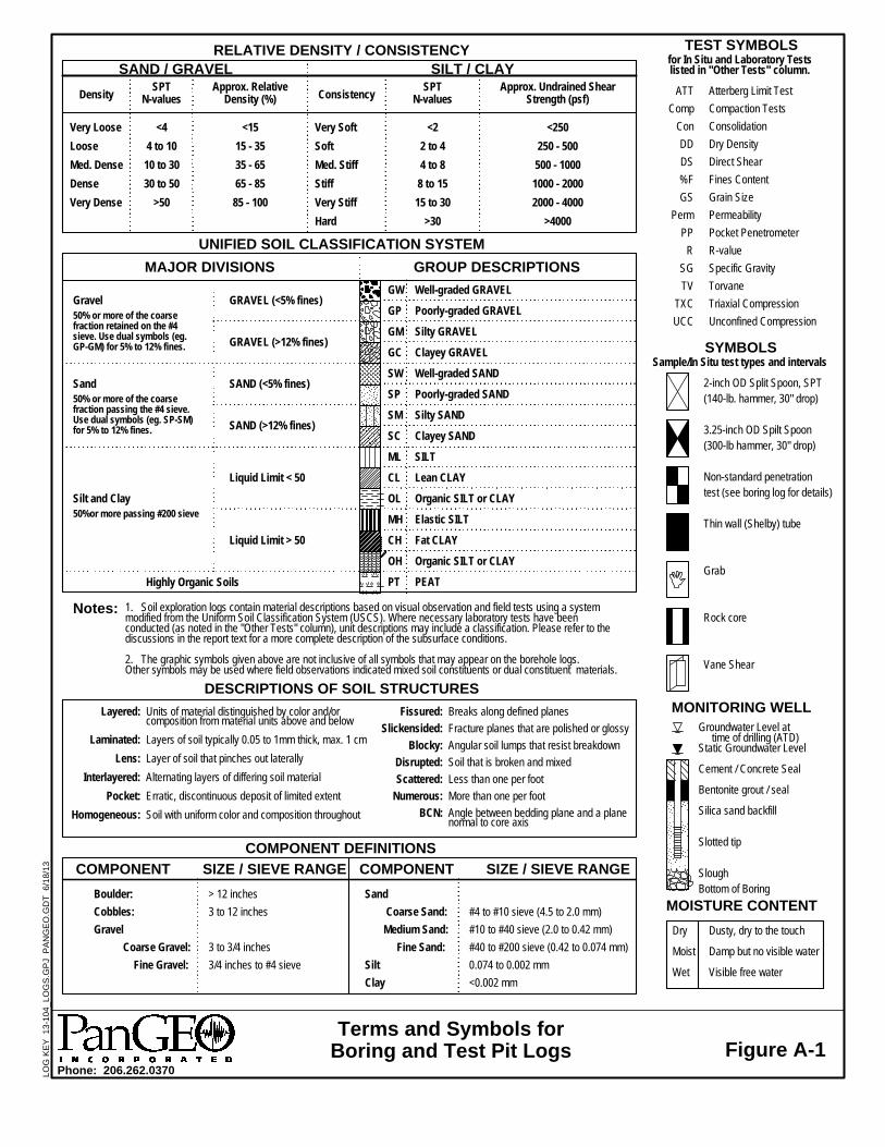
MOISTURE CONTENT
2-inch OD Split Spoon, SPT(140-lb. hammer, 30" drop)
3.25-inch OD Spilt Spoon(300-lb hammer, 30" drop)
Non-standard penetrationtest (see boring log for details)
Thin wall (Shelby) tube
Grab
Rock core
Vane Shear
Dusty, dry to the touch
Damp but no visible water
Visible free water
Terms and Symbols forBoring and Test Pit Logs
Density
SILT / CLAY
GRAVEL (<5% fines)
GRAVEL (>12% fines)
SAND (<5% fines)
SAND (>12% fines)
Liquid Limit < 50
Liquid Limit > 50
Breaks along defined planes
Fracture planes that are polished or glossy
Angular soil lumps that resist breakdown
Soil that is broken and mixed
Less than one per foot
More than one per foot
Angle between bedding plane and a planenormal to core axis
Very Loose
Loose
Med. Dense
Dense
Very Dense
SPTN-values
Approx. Undrained ShearStrength (psf)
<4
4 to 10
10 to 30
30 to 50
>50
<2
2 to 4
4 to 8
8 to 15
15 to 30
>30
SPTN-values
Units of material distinguished by color and/orcomposition from material units above and below
Layers of soil typically 0.05 to 1mm thick, max. 1 cm
Layer of soil that pinches out laterally
Alternating layers of differing soil material
Erratic, discontinuous deposit of limited extent
Soil with uniform color and composition throughout
Approx. RelativeDensity (%)
Gravel
Layered:
Laminated:
Lens:
Interlayered:
Pocket:
Homogeneous:
Highly Organic Soils
#4 to #10 sieve (4.5 to 2.0 mm)
#10 to #40 sieve (2.0 to 0.42 mm)
#40 to #200 sieve (0.42 to 0.074 mm)
0.074 to 0.002 mm
<0.002 mm
UNIFIED SOIL CLASSIFICATION SYSTEM
MAJOR DIVISIONS GROUP DESCRIPTIONS
Notes:
MONITORING WELL
<15
15 - 35
35 - 65
65 - 85
85 - 100
GW
GP
GM
GC
SW
SP
SM
SC
ML
CL
OL
MH
CH
OH
PT
TEST SYMBOLS
50%or more passing #200 sieve
Groundwater Level at time of drilling (ATD)Static Groundwater Level
Cement / Concrete Seal
Bentonite grout / seal
Silica sand backfill
Slotted tip
Slough
<250
250 - 500
500 - 1000
1000 - 2000
2000 - 4000
>4000
RELATIVE DENSITY / CONSISTENCY
Fissured:
Slickensided:
Blocky:
Disrupted:
Scattered:
Numerous:
BCN:
COMPONENT DEFINITIONS
Dry
Moist
Wet
1. Soil exploration logs contain material descriptions based on visual observation and field tests using a systemmodified from the Uniform Soil Classification System (USCS). Where necessary laboratory tests have beenconducted (as noted in the "Other Tests" column), unit descriptions may include a classification. Please refer to thediscussions in the report text for a more complete description of the subsurface conditions.
2. The graphic symbols given above are not inclusive of all symbols that may appear on the borehole logs.Other symbols may be used where field observations indicated mixed soil constituents or dual constituent materials.
COMPONENT SIZE / SIEVE RANGE COMPONENT SIZE / SIEVE RANGE
SYMBOLSSample/In Situ test types and intervals
Silt and Clay
Consistency
SAND / GRAVEL
Very Soft
Soft
Med. Stiff
Stiff
Very Stiff
Hard
Phone: 206.262.0370
Bottom of BoringBoulder:
Cobbles:
Gravel
Coarse Gravel:
Fine Gravel:
Sand
Coarse Sand:
Medium Sand:
Fine Sand:
Silt
Clay
> 12 inches
3 to 12 inches
3 to 3/4 inches
3/4 inches to #4 sieve
Figure A-1
Atterberg Limit Test
Compaction Tests
Consolidation
Dry Density
Direct Shear
Fines Content
Grain Size
Permeability
Pocket Penetrometer
R-value
Specific Gravity
Torvane
Triaxial Compression
Unconfined Compression
Sand50% or more of the coarsefraction passing the #4 sieve.Use dual symbols (eg. SP-SM)for 5% to 12% fines.
for In Situ and Laboratory Testslisted in "Other Tests" column.
50% or more of the coarsefraction retained on the #4sieve. Use dual symbols (eg.GP-GM) for 5% to 12% fines.
DESCRIPTIONS OF SOIL STRUCTURES
Well-graded GRAVEL
Poorly-graded GRAVEL
Silty GRAVEL
Clayey GRAVEL
Well-graded SAND
Poorly-graded SAND
Silty SAND
Clayey SAND
SILT
Lean CLAY
Organic SILT or CLAY
Elastic SILT
Fat CLAY
Organic SILT or CLAY
PEAT
ATT
Comp
Con
DD
DS
%F
GS
Perm
PP
R
SG
TV
TXC
UCC
LOG
KE
Y
13-1
04_L
OG
S.G
PJ
PA
NG
EO
.GD
T
6/18
/13
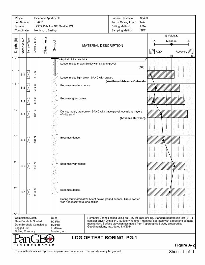
Asphalt: 2 inches thick.
Loose, moist, brown SAND with silt and gravel.(Fill).
Loose, moist, light brown SAND with gravel.(Weathered Advance Outwash).
Becomes medium dense.
Becomes gray-brown.
Dense, moist, gray-brown SAND with trace gravel; occasional layersof silty sand.
(Advance Outwash).
Becomes dense.
Becomes very dense.
Becomes dense.
Boring terminated at 26.5 feet below ground surface. Groundwaterwas not observed during drilling.
S-1
S-2
S-3
S-4
S-5
S-6
S-7
234
699
566
71019
151815
152927
152620
Remarks: Borings drilled using an RTC 60 track drill rig. Standard penetration test (SPT)sampler driven with a 140 lb. safety hammer. Hammer operated with a rope and catheadmechanism. Surface elevation estimated from Topographic Survey prepared byGeodimensions, Inc., dated 8/8/2014.
0
5
10
15
20
25
30
The stratification lines represent approximate boundaries. The transition may be gradual.
MATERIAL DESCRIPTION
Figure A-2
Oth
er T
ests
Sam
ple
No.
Completion Depth:Date Borehole Started:Date Borehole Completed:Logged By:Drilling Company:
Dep
th,
(ft)
Pinehurst Apartments
18-007
12303 15th Ave NE, Seattle, WA
Northing: , Easting:
26.5ft1/23/181/23/18J. MankeBoretec, Inc.
Sheet 1 of 1
Project:
Job Number:
Location:
Coordinates:
Sym
bol
Sam
ple
Typ
e
Blo
ws
/ 6
in.
354.0ft
N/A
HSA
SPT
Surface Elevation:
Top of Casing Elev.:
Drilling Method:
Sampling Method:
LOG OF TEST BORING PG-1
N-Value
0
Moisture LL
50
PL
RQD Recovery
100
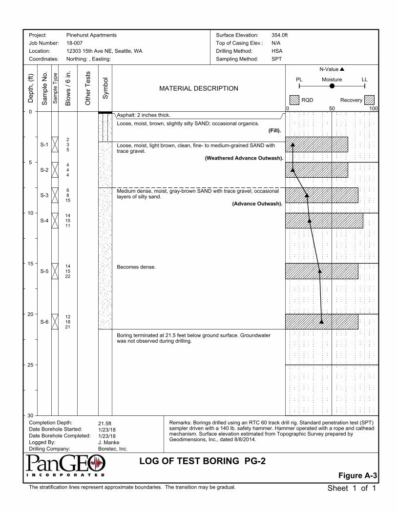
Asphalt: 2 inches thick.
Loose, moist, brown, slightly silty SAND; occasional organics.(Fill).
Loose, moist, light brown, clean, fine- to medium-grained SAND withtrace gravel.
(Weathered Advance Outwash).
Medium dense, moist, gray-brown SAND with trace gravel; occasionallayers of silty sand.
(Advance Outwash).
Becomes dense.
Boring terminated at 21.5 feet below ground surface. Groundwaterwas not observed during drilling.
S-1
S-2
S-3
S-4
S-5
S-6
235
444
6815
141511
141522
121821
Remarks: Borings drilled using an RTC 60 track drill rig. Standard penetration test (SPT)sampler driven with a 140 lb. safety hammer. Hammer operated with a rope and catheadmechanism. Surface elevation estimated from Topographic Survey prepared byGeodimensions, Inc., dated 8/8/2014.
0
5
10
15
20
25
30
The stratification lines represent approximate boundaries. The transition may be gradual.
MATERIAL DESCRIPTION
Figure A-3
Oth
er T
ests
Sam
ple
No.
Completion Depth:Date Borehole Started:Date Borehole Completed:Logged By:Drilling Company:
Dep
th,
(ft)
Pinehurst Apartments
18-007
12303 15th Ave NE, Seattle, WA
Northing: , Easting:
21.5ft1/23/181/23/18J. MankeBoretec, Inc.
Sheet 1 of 1
Project:
Job Number:
Location:
Coordinates:
Sym
bol
Sam
ple
Typ
e
Blo
ws
/ 6
in.
354.0ft
N/A
HSA
SPT
Surface Elevation:
Top of Casing Elev.:
Drilling Method:
Sampling Method:
LOG OF TEST BORING PG-2
N-Value
0
Moisture LL
50
PL
RQD Recovery
100
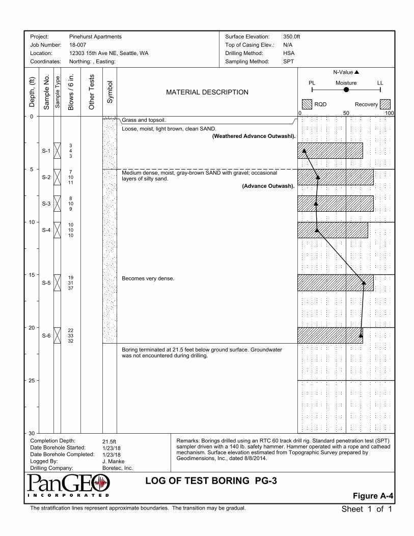
Grass and topsoil.
Loose, moist, light brown, clean SAND.(Weathered Advance Outwashl).
Medium dense, moist, gray-brown SAND with gravel; occasionallayers of silty sand.
(Advance Outwash).
Becomes very dense.
Boring terminated at 21.5 feet below ground surface. Groundwaterwas not encountered during drilling.
S-1
S-2
S-3
S-4
S-5
S-6
343
71011
8109
101010
193137
223332
Remarks: Borings drilled using an RTC 60 track drill rig. Standard penetration test (SPT)sampler driven with a 140 lb. safety hammer. Hammer operated with a rope and catheadmechanism. Surface elevation estimated from Topographic Survey prepared byGeodimensions, Inc., dated 8/8/2014.
0
5
10
15
20
25
30
The stratification lines represent approximate boundaries. The transition may be gradual.
MATERIAL DESCRIPTION
Figure A-4
Oth
er T
ests
Sam
ple
No.
Completion Depth:Date Borehole Started:Date Borehole Completed:Logged By:Drilling Company:
Dep
th,
(ft)
Pinehurst Apartments
18-007
12303 15th Ave NE, Seattle, WA
Northing: , Easting:
21.5ft1/23/181/23/18J. MankeBoretec, Inc.
Sheet 1 of 1
Project:
Job Number:
Location:
Coordinates:
Sym
bol
Sam
ple
Typ
e
Blo
ws
/ 6
in.
350.0ft
N/A
HSA
SPT
Surface Elevation:
Top of Casing Elev.:
Drilling Method:
Sampling Method:
LOG OF TEST BORING PG-3
N-Value
0
Moisture LL
50
PL
RQD Recovery
100