Embed Size (px)
Citation preview


Annexure –VIII
UNIVERSITY GRANTS COMMISSION
BAHADUR SHAH ZAFAR MARG
NEW DELHI – 110 002.
Final Report of the work done on the Major Research Project.
1. Project report No. 1st
/2nd
/3rd
/ Final : Final
2. UGC Reference No. : F.No.-43-299/2014 (SR)
3. Period of report: from : 01/07/2015 to 30/06/2018
4. Title of research project : Studies on Fuzzy Logic Thermal
Compensation Technique for High Speed
Precision Machine.
5. a) Name of the Principal Investigator : Dr. Mudholkar Ravindra Ramchandra
b) Deptt. : Department of Electronics
c) University/College where work has
progressed : Shivaji University, Kolhapur
India- 416004
6. Effective date of starting of the project : 01/07/2015
21/04/2016(Grant Received)
7. Grant approved and expenditure incurred during the period of the report:
a) Total amount approved Rs
b) Total expenditure Rs
: Rs. 9, 59,000/- (Nine Lakh Fifty Nine
Thousand only)
: Rs. 4, 39, 924/- ( Four Lakh Thirty Nine
Thousand Nine Hundred Twenty Four
only)
c) Report of the work done: Report Enclosed
i. Brief objective of the project: (See Annexure-I)
ii. Work done so far and results achieved and publications, if any, resulting
from the work (Give details of the papers and names of the journals in
which it has been published or accepted for publication (See Annexure-I)
iii. Has the progress been according to original plan of work and towards
achieving the objective? if not, state reasons: Yes


Annexure I
Objective
Studies on Fuzzy Logic Thermal Compensation Technique for High Speed Precision Machine.
Methodology
The entire research work will be consolidated as follows:
Study temperature response of spindle at various rpm and develop transfer function.
Simulation and performance study of fuzzy optimized cooling system controller using
simulating tools of MATLAB.
Hardware descriptions of the fuzzy logic controller (FUZZIER, RULE-BASE, and
DEFUZZIER modules) in Altera Quartus Development Environment.
Simulation and performance study of overall fuzzy optimized embedded system using
simulating tools of MATLAB/ Altera Quartus Development Environment.
After successful simulation, Implemention of the system hardware, which mainly
consists of Sensor system, Signal conditioning and dedicated fuzzy logic controller
design.
Optimization of process through tuning approach if required.
Work done
The literature survey reveals that temperature plays vital role in machine tool
performance. The spindle system is the core component of machine tool structure and its
performance dominates machine accuracy and productivity. Internal heat sources in machine tool
cause temperature distribution in structures and resulting heat flow causes thermal deformation
of component. The complex thermal behavior is the predominant factor for determining the
performance of machine tool. As the important component in machine tool, the spindle would
generate large amounts of heat when it is running at a high speed. The amount of heat generated
results in thermal error. Thermal error can be reduced by a number of methods as Thermal
Error Avoidance method can only be implemented in the phase of machine designing and
construction. Thermal Error Control is used to control the amount of heat transferred into the
spindle system or to avoid the generation of the non-uniform temperature distribution. In order to
control the thermal error jacket cooling is used which is complex system. Thermal error
compensation is more convenient and economical, as its principle is simple and can be easily
executed in the factory with minimal cost. Therefore to eliminate the thermal error thermal
compensation method has been used.
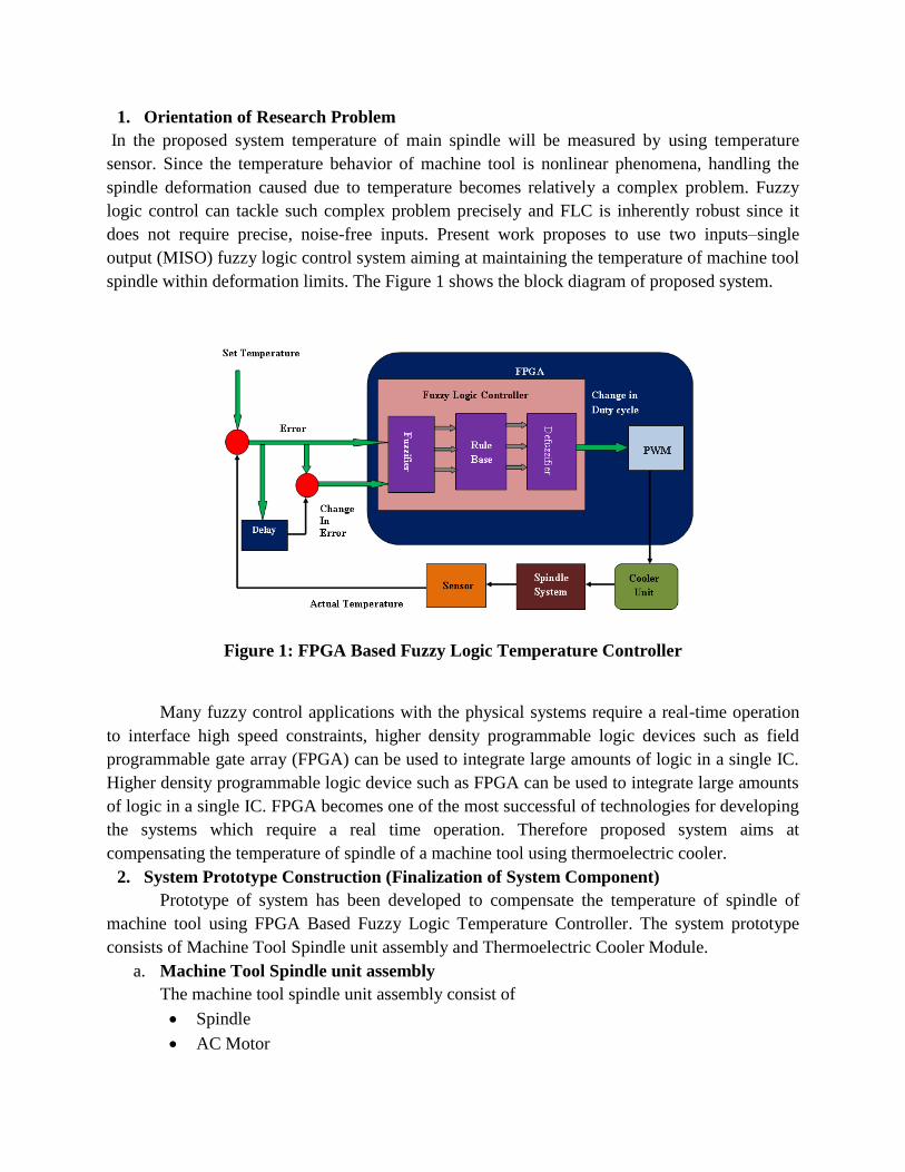
1. Orientation of Research Problem
In the proposed system temperature of main spindle will be measured by using temperature
sensor. Since the temperature behavior of machine tool is nonlinear phenomena, handling the
spindle deformation caused due to temperature becomes relatively a complex problem. Fuzzy
logic control can tackle such complex problem precisely and FLC is inherently robust since it
does not require precise, noise-free inputs. Present work proposes to use two inputs–single
output (MISO) fuzzy logic control system aiming at maintaining the temperature of machine tool
spindle within deformation limits. The Figure 1 shows the block diagram of proposed system.
Figure 1: FPGA Based Fuzzy Logic Temperature Controller
Many fuzzy control applications with the physical systems require a real-time operation
to interface high speed constraints, higher density programmable logic devices such as field
programmable gate array (FPGA) can be used to integrate large amounts of logic in a single IC.
Higher density programmable logic device such as FPGA can be used to integrate large amounts
of logic in a single IC. FPGA becomes one of the most successful of technologies for developing
the systems which require a real time operation. Therefore proposed system aims at
compensating the temperature of spindle of a machine tool using thermoelectric cooler.
2. System Prototype Construction (Finalization of System Component)
Prototype of system has been developed to compensate the temperature of spindle of
machine tool using FPGA Based Fuzzy Logic Temperature Controller. The system prototype
consists of Machine Tool Spindle unit assembly and Thermoelectric Cooler Module.
a. Machine Tool Spindle unit assembly
The machine tool spindle unit assembly consist of
Spindle
AC Motor

VFD (Variable frequency drive)
Belt-Pully system
Brake system
The spindle is externally driven by single to three phase asynchronous ac motor. The
maximum rpms (revolutions per minute) of the motor are 2800. It is Series Motor, It has 2 poles,
delta connected and has power of 1 HP. In order to obtain variable speed (rpm) Variable
frequency drive (VFD) has been used. Its input is single phase while output is three phase. It can
change frequency from 0.1 Hz to 600 Hz. A variable frequency drive controls the speed of an
AC motor by varying the frequency supplied to the motor. The drive also regulates the output
voltage in proportion to the output frequency to provide a relatively constant ratio of voltage to
frequency (V/Hz) . In verge of the obtaining the spindle roational speed higher than 2800 the
belt-pully system is being employed. The driver pulley and driven pulley diameter are selected in
the 7:3 ratio. So the speed of spindle will increase seven times greater than that of motor speed.
The roatational speed (rpm) of spindle are measured by using non-contact tachometer. In the
present system there is no load hence braking system is designed to apply radial friction on
spindle. Therefore with friction applied heat will be generated.The photo of machine tool spindle
tool assembly is displayed in Figure 2.
Figure 2: Machine Tool Spindle Unit Assembly (Top View)
b. Thermoelectric Cooler
Figure 3: Picture of Thermoelectric Cooler Module
The Thermoelectric cooler Module containing peltier element TEC1-12706 is used which has
maximum cooling power of 57 watt and maximum operating temperature is 67 0C. It can directly

powered by DC electricity sources TEC1-12706 operates on 12 V, 6 Amp DC supplies. The peltier
element has two sides hot and cold. In the TEC model the cold side of TEC is attached to the cooling
load component and heat sink is attached on the hot side. The cooling side of the TEC is forced by a
fan that carries cool air onto the spindle. The heat from the load is absorbed by cooling side and heat
produced on the hot side is pumped away in the atmosphere by using the heat sink.
3. Data Acquisition System
Figure 4: Connection Diagram of ADC with the FPGA Board
In order to measure the temperature of spindle of machine tool FPGA based data acquisition system
has been designed and implemented.
Figure 5: Data Acquisition System
With the help of Data Acquisition system the temperature of spindle was measured. 1000 to 4500
rpm. The transfer function estimated presented in Table 1. The transfer function was estimated and
simulated using Matlab-Simulink.
Table 1:Transfer Functions
Sr. No. Rotational
speed(rpm)
Transfer Function
01 1000 5 04 .8 8
(s )5 1 3 1
sG e
s
02 1500 2 07 .8 1
(s )2 4 5 .5 1
sG e
s
03 2000
2 08 .7 9(s )
3 4 6 1
sG e
s
04 2500
1 19 .7 6(s )
3 5 6 1
sG e
s

05 3000 1 0 .51 0 .2 5
(s )3 2 2 .7 5 1
sG e
s
06 3500
01 5 .1 2(s )
3 1 6 1
sG e
s
07 4000
01 6 .6(s )
4 3 5 .7 1
sG e
s
08 4500
01 8 .0 7(s )
3 8 6 .6 1
sG e
s
Transfer Function of Thermoelectric Cooler
02 .6G (S )=
5 0 1
sT em p era tu ree
C u rren t s
(1)
Figure 6: Simulink Model for Testing Estimated TF of Thermoelectric Cooler.
Figure 7:Comparison between real time response and modeled TF response
Figure 7:spindle Temperature at 1000 rpm Figure 8:Spindle Temperature at 1500 rpm

Figure 9:spindle Temperature at 2000 rpm Figure 10:spindle Temperature at 2500 rpm
Figure 11:spindle Temperature at 3000 rpm Figure 12:spindle Temperature at 3500 rpm
Figure 13:spindle Temperature at 4000 rpm Figure 14:spindle Temperature at 4500 rpm
The real time response and simulated response are in good agreement. The simulation response of
rpm from 1000 to 4500 rpm plotted together. The plot shows that as the rotational speed increases the
temperature of spindle increases.
Figure 15 : Thermal Behaviour Analysis

4. Fuzzy Temperature Controller Implementation
Figure 16: Structure of Fuzzy Temperature Controller
Fuzzy Temperature controller system consist of standard reference temperature, processing
unit, plant and feedback system. The reference temperature is set during the programming of
processing unit. The processing unit used for the implementation of fuzzy temperature controller is
Altera Cyclone IV EP4CE115F29 FPGA device (DE2-115 FPGA Board). The fuzzy controller
implemented in FPGA will produce control signal i.e. PWM (pulse width modulation) signal. This
PWM output will drive the thermoelectric cooler module. TEC1-12706 thermoelectric cooler has
been used for the cooling of spindle unit. The fuzzy temperature control system is as shown in Figure
16. The temperature feedback is applied using FPGA based temperature data acquisition system. The
fuzzy temperature controller is implemented in Fuzzy Logic. The feedback signal is processed using
FPGA and error, change in error these signals are engendered and control signal is generated through
FPGA to control the speed of Thermoelectric Cooler to compensate the temperature of spindle of
machine tool
4.1. PWM Driver Circuit
PWM (Pulse width modulation) is used to control the power of thermoelectric
cooler in order to maintain the temperature of spindle of a machine tool within a required range. In
industrial application for refrigeration H Bridge has been used which provides required power for
cooling as well as heating as per the application. In present system heat is generated so cooling is
required. Therefore only one section of H-Bridge containing driver IC U1 and MOSFET Q1 and Q2
was used for cooling purpose. Thermoelectric cooler uses peltier element that can be used for
heating or cooling purpose. If the supply to the peltier is given in accurate polarity then it provides
cooling and if the polarity is reversed then heating occurs. Here we are using peltier for cooling. This
circuit accepts the PWM gating pulses by implementing fuzzy temperature controller in FPGA and
provides control output to the TEC to maintain the temperature of spindle within a range.

Figure 17 : PWM driver circuit
To put together voltage level of PWM driver circuit (See Figure 17) compatible with FPGA
Board that supplies on board 3.3 V supplies, voltage regulator IC LM 1117 has been used which
provides 3.3 V regulated supply (See Figure 18). The 12 V input supply is given through 12V/10
Amp SMPS and generated output was provided to the H-Bridge.
Figure 18: LM 1117 voltage Regualtor
In the driver circuit Power MOSFET IRF 840 is used as switching device which is
connected in series with the TEC. It provides fast switching speed. IRS 2110 is high voltage, high
speed N-Channel power MOSFET driver with two separate channels for high and low side reference
voltage. It is operational up to 500 V/ 600 V and provides output up to 10 V to 20 V. It is compatible
to voltage level of 3.3 V.
4.2. PWM Implementation
Thermoelectric cooler is driven by PWM (pulse width modulated) signal. The duty
cycle of PWM signal is controlled by fuzzy controller. In fuzzy temperature controller the
temperature of spindle of machine tool is measured by IC sensor is feeded back.

Figure 19: Photo of H Bridge
The difference between the standard reference temperature and the present temperature is computed
as error and it is applied as input to the fuzzy controller. This error is processed by fuzzy controller to
find out the percentage of error and generate the required amount of PWM signal to retain the
temperature of spindle of a machine tool at specified value. The PWM is implemented in FPGA that
generates PWM signal of 1 KHz (See Figure 20).
Figure 20: PWM Waveform Generation
5. Matlab simulation of Fuzzy Logic Controller
The fuzzy temperature controller has been designed and simulated using Fuzzy Logic Tool Box and
Simulink of Matlab Ver 2015b. The Simulink model for MISO (Many Input and Single output)
displayed in Figure 21. It has two inputs Error and Change in Error these inputs are processed by
fuzzy logic temperature controller and provides the control signal to the TEC. The input and output
membership functions used in the fuzzy controller are shown in. Figure 22 and. Figure 23 and Figure
24. The range of input and output variables is represented in Table 2. The rules are represented in
Table 3.

Figure 21:Simulink Model for Fuzzy Logic Controller
Figure 22: Membership Function for Input Variable “error”
Figure 23: Membership Function for Input Variable “Change in Error (CE)”
Figure 24: Membership Function for Output Variable “Control Signal”
Input and Output membership functions contains trapezoidal and triangular membership functions.
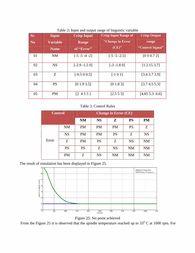
Table 2: Input and output range of linguistic variable
Sr.
No
Input
Variable
Name
Crisp Input
Range
of “Error”
Crisp Input Range of
“Change in Error
(CE)”
Crisp Output
range
“Control Signal”
01 NM [-5 -5 -4 -2] [-5 -5 -2.5] [0 0 0.7 2]
02 NS [-2.9 -1.5 0] [-3 -1.8 0] [1 2.15 3.7]
03 Z [-0.5 0 0.5] [-1 0 1] [3.4 3.7 3.9]
04 PS [0 1.9 3.5] [0 1.8 3] [3.7 4.5 5.3]
05 PM [2 4 5 5 ] [2.5 5 5] [4.65 5.3 6.6]
Table 3. Control Rules
The result of simulation has been displayed in Figure 25.
Figure 25: Set point achieved
From the Figure 25 it is observed that the spindle temperature reached up to 330 C at 1000 rpm. For
Control Change in Error (CE)
NM NS Z PS PM
Error
NM PM PM PM PS Z
NS PM PM PS Z NS
Z PM PS Z NS NM
PS PS Z NS NM NM
PM Z NS NM NM NM

the demonstration purpose 270C is chosen as Ideal Temperature for a spindle system prototype.
Thermoelectric cooler is able to reduce the temperature by 60 C.
Figure 26: Error Obtained
Figure 26 shows the result of simulation of spindle system prototype. The simulation is performed
from 0 to 5000 sec. The Error in simulation is 0.0150 C that is 0.25%. The settling time for the
simulation is 2000 sec. Figure 28 shows the output control signal generated by Fuzzy Logic
Temperature Controller that supplied to the Thermoelectric Cooler that compensate the temperature
of spindle. The control signal settles down at 2900 rpm.
Figure 27: Change in Error (CE)
Figure 28: Control Signal
Figure 29: Three dimensional surface view

6. Implementation of Fuzzy Temperature Controller in FPGA.
The fuzzy temperature controller has been implemented to compensate the temperature of the
spindle at 1000 rpm. In the present system the fuzzy logic temperature control has been implemented
by using software/Hardware Codesign approach on FPGA board. The hardware system has been
implemented using SOPC builder tool that is Qsys in combination with Quartus prime Edition 15.1.
Qsys allows creating a system based on Nios II Processor. The inputs to the fuzzy temperature
controller are error (E) and change in error (CE) and the output signal of controller is connected to
Pulse Width Modulation (PWM) Generator. PWM controls the cooling of Thermoelectric Cooler by
changing its current which controls the temperature of spindle. The simulation and performance
study of fuzzy Logic Temperature Controller (FLTC) has been performed with MATLAB. The Nios
II processor software has been written in C language using the Nios II IDE software provided by
Altera that is NIOS II Software Build Tool (SBT) for Eclipse. The hardware and software has been
implemented on Cyclone IV EP4CE115F29C7 DE2-115 FPGA Board. The design flow of the
system has been displayed in Figure 30.
Figure 30: Hardware and software codesign
6.1.Implementing System using NIOS II soft core processor
Altera’s Nios II is a soft processor, defined in a hardware description language that can be
implemented in altera’s FPGA devices by using the Quartus II CAD system. The Nios II processor
and the interfaces are interconnected to other components of FPGA board by means of the
interconnection network called the Avalon Switch Fabric Network. I/O interfaces are instantiated to
offer I/O connections to the system. The JTAG UART interface provides connection between
universal serial bus (USB) links providing circuit that is USB blaster and the host computer to which
DE2-115 FPGA Board has been connected. The USB blaster along with JTAG module makes it
possible to perform operations such as downloading programs into memory, starting and stopping
execution, setting program breakpoints, and collecting real-time execution trace data. By using USB
Blaster circuitry host computer can control Nios II processor. The Component required for
implementation of Nios II System is displayed in Figure 31.

Figure 31: A Nios II System Implemented on FPGA Board
6.2. Implementation of the Nios System with Qsys Tool
The temperature of spindle of a machine tool has been compensated by using fuzzy logic that
is implemented in FPGA. The system to be implemented is displayed in Figure 32. The DE2-115
FPGA board has been used. The temperature of spindle of a machine tool has been measured with the
IC temperature sensor LM 35. In order to process the analog data into digital and to record the real
time temperature analog to digital converter is required. As the FPGA board has no ADC therefore
external ADC ADS 7841 has been interfaced with the FPGA. In order to provide required cooling to
control the temperature of spindle of machine tool thermoelectric cooler TEC1-12706 has been used.
The control signal is generated through PWM circuit which is interfaced with the FPGA board. The
control signal has been generated by fuzzy temperature controller. Field Programmable Gate Arrays
(FPGA) provides very good hardware design flexibility. The thermoelectric cooler TEC-12706
requires operating voltage 0 to 12 V and current of 6 Amp. The advantage of using FPGA is that it is
used to generate High-frequency variable duty cycle PWM output. The DE2-115 Board contains an
FPGA that can be programmed that it includes NIOS-II soft core processor.
All components are interfaced with the GPIO pins of FPGA Board. The Quartus software 15.1 along
with Nios II Embedded design suit (EDS) has been used to develop Nios II hardware system design
that create software program that runs on Nios II system and the components are interfaced on Altera
development board.

Figure 32:The FPGA Based system
6.3 The Quartus Software
Altera Quartus II is programmable logic device design software produced by Altera. Quartus
II software features include SOPC Builder and Qsys tool. SOPC builder tool in Quartus II software
that eliminates manual system integration tasks by automatically generating interconnect logic and
creating a test bench to verify functionality while Qsys is a system integration tool that is the next
generation of SOPC Builder.
Figure 33: Quartus Prime Development Suite.
6.4 System Generation through Qsys Tool
The Qsys tool allows a designer to choose the components that are desired in the system by selecting
these components in a graphical user interface. It then automatically generates the hardware system
that connects all of the components together.
In order to implement the system following functional units are used.
Nios II processor
On-chip memory
Two parallel I/O interfaces
JTAG UART interface for communication with the host computer
The following steps are performed to implement the system
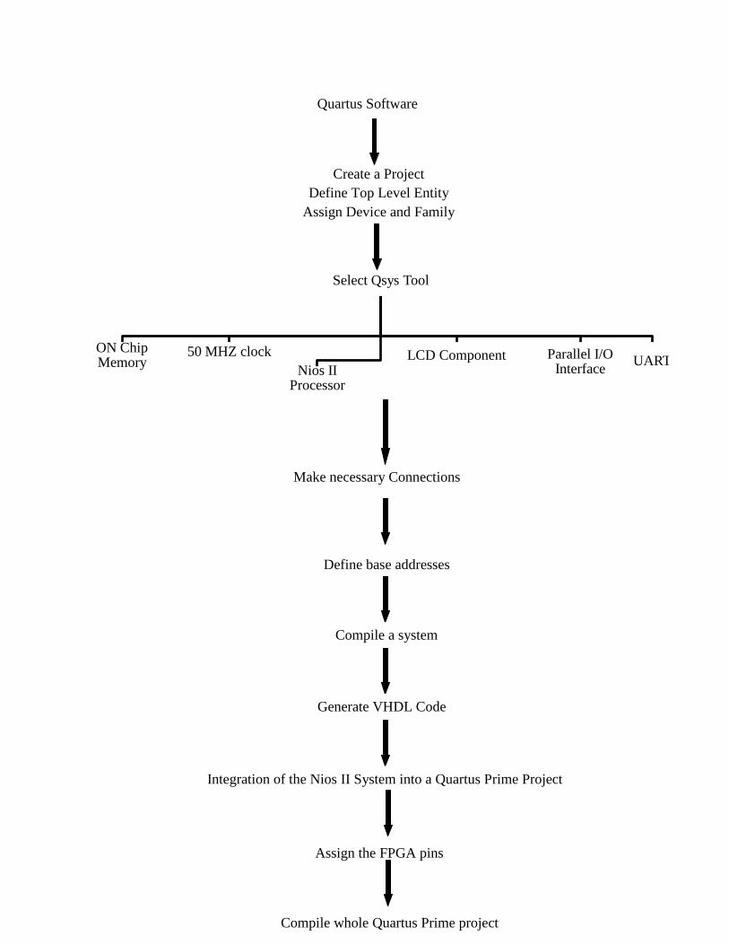
Select Qsys Tool
ON Chip Memory
50 MHZ clock
Nios II Processor
LCD Component Parallel I/O Interface
UART
Make necessary Connections
Define base addresses
Compile a system
Generate VHDL Code
Integration of the Nios II System into a Quartus Prime Project
Assign the FPGA pins
Compile whole Quartus Prime project
Create a Project
Define Top Level Entity
Assign Device and Family
Quartus Software

The designed circuit has been compiled. The system has been compiled successfully the result of
compilation was displayed in Figure 34.
Figure 34:Compilation Result
After the successful compilation device utilization report is obtained. That is represented in Table 4.
Table 4. Device Utilization Report
Used Available Utilization
Total Logic Elements 1,778 114,480 2 %
Total combinational functions 1,653 114,480 1 %
Dedicated logic registers 952 114,480 < 1 %
Embedded Multiplier 9-bit
elements
0 532 0
Total registers 952 -------- ------
Total Pins 47 529 9%
Total memory bits 1,648,64
0
3,981,312 41 %
Total PLLs 0 4 0%
From the Table 7, it has been observed that utilization of logic elements is only 2% that is 1,778
elements out of 114,480 elements are used. Total combinational functions used are 1,653 that is 1%
and use of dedicated logic registers less than 1%.
6.5. Programming and Configuring the FPGA device on the DE2-115 board
After successful compilation programmer has been selected from the tool option. The

hardware set up displays the present hardware. USB Blaster 0 has been selected as displayed Figure
35.a. then .sof file has been added program has been running on the hardware as displayed in Figure
35.b. After running the program the result is displayed on FPGA Board as shown in Figure 36.
Figure 35.a. Hardware Set up
Figure 35. b. Hardware Set up
Figure 36: Program Execution on FPGA Board

6.6 Nios II Software Development Tool (SBT) for Eclipse
The software development task has been performed for Nios Processor system by using Nios II
software development tool (SBT) for Eclipse. The system was generated with Qsys then C
application code has been designed with the Nios II SBT for Eclipse. The following steps are
performed
After running the program on FPGA Board the spindle temperature starts compensating the spindle
temperature as displayed in Figure 37.

Figure 37: Implementation of FPGA Based Fuzzy Logic Spindle Temperature Compensation.
The Figure 37 shows FPGA Based Fuzzy Logic temperature controller to compensate the
temperature of spindle of machine tool. The result of compensation is displayed in Figure 38. The
result of compensation presents that the spindle temperature which reached up to 330C after
compensation it attains the set temperature of 270C.
Figure 38. Real time Response of spindle temperature compensation system implemention.
The time response of spindle temperature compensation system shows that the system has time delay
of 30 Sec and the system settles down after 1480 seconds.
References:
1. Horejs, O., Mares, M., and Hornych, J. (2014). A General Approach to Thermal Error
Modelling of Machine tools, Conference on Machines et. Usinage à Grande Vitesse (MUGV),
Clermont Ferrand, France, 1-10.
2. Horejs, O., Mares, M., Kohut, P., Barta, P., and Hornych, J. (2010). Compensation of
Machine Tool Thermal Errors Based on Transfer Functions, MM Science Journal, 162-165.
3. Mathworks Inc. MATLAB, User Manual for MATLAB and Simulink Toolbox,

www.mathworks.in/help/pdf_doc/matlab/getstart.pdf.
4. Patil, P. S., and Mudholkar, R. R. (2016). Cooling Techniques for a Spindle of Machine Tool,
International Journal of Engineering and Computer Science, 5 (12), 19653-19656.
5. Lacalle, N. L. D., and Mentxaka, A. L. (2008), Technology & Engineering e-book on
Machine Tools for High Performance Machining, https://books.google.co.in/books?isbn
=1848003803.
6. R. L. Judd, K. Aftab, Elbestawi, M. A. (1994). An Investigation of the use of Heat Pipes for
Machine Tool Spindle Bearing Cooling, International Journal of Machine Tools
Manufacture, 34(7), 1031-1043.
7. Chiller Wikipedia: https://en.wikipedia.org/wiki/Chiller. Browsed on October 2017.
8. Cooling Systems or Chillers, spindle parts and services, LLC (2016).
http://www.spsspindle.com/cooling-systems chillers. Browsed on October 2017.
Publications
Journals
1. Poonam S. Patil, R. R. Mudholkar, “Cooling Techniques for a Spindle of Machine Tool”,
International Journal Of Engineering And Computer Science, Volume 5 Issue 12 Dec. 2016,
PP: 19653-19656.
2. Poonam S. Patil, R. R. Mudholkar, “Thermal Error Modeling In Machine Tool”, International
Journal of Engineering Science and Technology (IJEST), pp:344-352, Vol. 9 No.05 May
2017
3. Poonam S. Patil, R.K. Kamat, R. R. Mudholkar, “TF Estimation and Thermal Behavioral
Analysis of Spindle Cooler System”, Research Journal of Engineering and Technology. 9(1):
January- March, 2018.
Conference
1. Poonam S. Patil, R.R. Mudholkar “Student Performance Evaluation By Different
Defuzzification Techniques” International Interdisciplinary Conference On Curriculum
Reformsin Higher Education: Global Scenario (IICCRHE-2018) February 4-6, 2018.

Annexure II
Sr. No Title Name
a) Manpower Trained Poonam Siddu Patil (Project Fellow)
b) Publications of
Result
1. Poonam S. Patil, R. R. Mudholkar, “Cooling
Techniques for a Spindle of Machine Tool”,
International Journal Of Engineering And Computer
Science, Volume 5 Issue 12 Dec. 2016, PP: 19653-
19656.
2. Poonam S. Patil, R. R. Mudholkar, “Thermal Error
Modeling In Machine Tool”, International Journal of
Engineering Science and Technology (IJEST), pp:344-
352, Vol. 9 No.05 May 2017
3. Poonam S. Patil, R.K. Kamat, R. R. Mudholkar, “TF
Estimation and Thermal Behavioral Analysis of Spindle
Cooler System”, Research Journal of Engineering and
Technology. 9(1): January- March, 2018.
c) Ph.D awarded Ph.D Registered
Student Name: Poonam Siddu Patil
Guide Name: Dr. R. R. Mudholkar
Date of Registration:01/07/2015
Spiral Bound Ph.D Thesis submitted for Scrutiny.
Title of Thesis: FPGA Based Fuzzy Logic Spindle
Temperature Compensation

Annexure- IX
UNIVERSITY GRANTS COMMISSION
BAHADUR SHAH ZAFAR MARG
NEW DELHI – 110 002
PROFORMA FOR SUBMISSION OF INFORMATION AT THE TIME OF SENDING
THE FINAL REPORT ON THE WORK DONE ON THE PROJECT
1. Title of the project :
Studies on Fuzzy Logic Thermal Compensation
Technique for High Speed Precision Machine
2. Name and Address of the
Principal Investigator :
Dr. Mudholkar Ravindra Ramchandra
Shivam, 5, Jadhav Park, Line Bazar Kasaba Bawada
Kolhapur, INDIA – 416006. Mob. No.:-9637774815,
Email : [email protected]
3. Name and Address of The
Institution :
Department of Electronics
Shivaji University, Kolhapur, India – 416004
4. UGC Approval Letter No. and
Date :
F.No.-43-299/2014(SR) dated 29 December 2015
5. Date of Implementation
: 01/07/2015
22/04/2016(Grant Received)
6. Tenure of the Project :
3 Years w. e. f 01/07/2015
7. Total Grant Allocated :
Rs.9,59,000/- (Nine Lakh Fifty Nine Thousand Only)
8. Total Grant Received : :
Rs.5,99,000/- (Five Lakh Ninety Nine Thousand Only)
9. Final Expenditure :
Rs.4,39,924/- (Four Lakh Thirty Nine Thousand Nine
Hundred Twenty Four Only)
10. Title Of The Project :
Studies on Fuzzy Logic Thermal Compensation
Technique for High Speed Precision Machine
11. Objectives of The Project:
:
To design and implementation of Real Time Thermal
Compensation of High Speed Precision Machine by
Using the Fuzzy Control of The Cooling System.

12. Whether Objectives Were
Achieved:(Give Details) :
Objectives were achieved.
The following objectives has been successfully achieved
To design and fabricate the laboratory scale
machine spindle system.
To design and implement the signal conditioning
system for temperature control system.
To design and implement fuzzy control
algorithm for temperature controller.
To generate VHDL coding for fuzzy inference
To implement the Fuzzy Logic Control
Algorithm in FPGA.
To present the system response analysis and
performance of proposed system.
13. Achievements from the Project
:
Real Time Thermal Compensation of High Speed
Precision Machine by Using the Fuzzy Control of The
Cooling System has been achieved.
14. Summary of the Findings:
(In 500 Words) :
See Annexure I
15. Contribution to the Society
(Give Details) : The fuzzy temperature control system for spindle of
machine tool based on FPGA using thermoelectric
Cooler is unique due to its simplicity.
Present system uses the standard temperature
maintaining approach which is suitable for all type of
machine than predictive type of machine.
Due to reconfigurable hardware platform the system
adopted for other machine tool with some changes.
16. Whether Any Ph.D Enrolled/
Produced Out Of The Project:
: Registration Date: 01/07/2015
Name of research student: Poonam Siddu Patil
Research Topic: FPGA based Fuzzy Logic Spindle
Temperature Compensation
Research Guide: Dr. Mudholkar Ravindra Ramchandra
Spiral Bound Ph.D Thesis submitted for Scrutiny.


Annexure I
Summary of the Findings:
Machine tool is a stationary power-driven machine that is used to shape or form parts
made of metal or other materials. The spindle is the drive component of machine tool. The belt
driven spindle is used in the present system. The spindle generate large amount of heat as the
rotational speed increases. This changes property of material that results in thermal error.
Thermal error can be reduced by using thermal error avoidance method, thermal error control
and thermal error compensation method. Thermal error compensation method is used it can be
implemented in any stage of machine from designing to working. IC sensor is used to measure
the temperature of spindle since it has good linearity, wide power range, and it is small and easy
to install so that no compensating circuit is needed. In the present system two inputs–single
output (MISO) fuzzy logic control system aiming at maintaining the temperature of machine tool
spindle within deformation limits. A large number of fuzzy control applications require a real-
time operation to interface high speed constraints. As the FPGA’s becomes one of the most
successful of technologies for developing the systems for a real time operation.
In order to compensate the temperature of spindle of machine tool thermoelectric cooling
method has been used. Air to air thermoelectric cooler consisting of peltier element with two
passive heat sinks on both sides are used. As the industrial standard temperature is 200 C the
Single Input and Single output (SISO) system and Many Input and single output (MISO) system
has been designed and implemented. Matlab-Simulink is used for the simulation of SISO and
MISO system.
The different method of cooling are discussed, and the thermoelectric cooling method
was explained. Transfer function of already existing thermoelectric cooling system has been
studied. The work presents the simulation result of fuzzy temperature controller to achieve the
set temperature of 200 C and 27
0 C. It also presents the resulting temperature after compensation.
System prototype has been constructed to measure the spindle temperature of machine
tool. Prototype consists of spindle, VFD (Variable frequency drive) connected to the AC Motor
that drives the spindle with belt and pulley system. Brake system is used to apply the radial
friction so heat can be generated. FPGA based data acquisition system has been designed. ADC

ADS 7841 is used to convert the analog information into digital. Real time response of
temperature spindle at different rotational speed is measured and the transfer functions are
estimated. Also, the cooling response of Thermoelectric Cooler is observed. For the simulation
of transfer function of Matlab Simulink is used. In order to control the airflow of TEC PWM
implemented in FPGA.
Fuzzy Logic Temperature Controller for the compensation of spindle temperature at 1000
rpm has been implemented by using Hardware-software codesign.Quartus prime Edition 15.1.
Qsys was used to create a system based on Nios II Processor.The Nios II processor software has
been written in C language using the Nios II IDE software provided by Altera that is NIOS II
Software Build Tool (SBT) for Eclipse In order to compensate the temperature of spindle of
machine tool, Fuzzy logic temperature controller is implemented in FPGA by using hardware
and software codesign. The results of spindle temperature compensation are tested and verified.
The Hardware platform
Cyclone IV EP4CE115F29C7DE2-115 FPGA Board.
The software platform
Quartus prime Edition 15.1.
Qsys tool
NIOS II Software Build Tool (SBT) for Eclipse
After the successful compilation the system has been implemented on FPGA board. It was
observed that total logic elements used are only 2 % that is 1,778. Total combinational functions
used are only 1%.