Embed Size (px)
Citation preview

Technical Specification Transport and Main Roads Specifications MRTS222 Electronic School Zone Signs November 2012
SUPERSEDED

Transport and Main Roads Specifications, November 2012
Copyright
http://creativecommons.org/licenses/by/3.0/au/
© State of Queensland (Department of Transport and Main Roads) 2014
Feedback: Please send your feedback regarding this document to: [email protected]
SUPERSEDED

Contents
1 Introduction .................................................................................................................................... 1 2 Definition of terms ......................................................................................................................... 1 3 Reference documents ................................................................................................................... 2 4 Quality system requirements ....................................................................................................... 3 4.1 Samples for acceptance ................................................................................................................. 3 5 Functional requirements ............................................................................................................... 3 5.1 General ........................................................................................................................................... 3 5.2 Sign Types ...................................................................................................................................... 4
5.2.1 Type 1 - Enhanced school zone speed limit sign – TC1783 .......................................... 4 5.2.2 Type 2 – Variable speed limit sign – TC1785 ................................................................ 5 5.2.3 Type 3 – School zone speed limit sign speed activated – TC1786 ............................... 5
6 Mechanical & physical requirements........................................................................................... 6 6.1 General ........................................................................................................................................... 6 6.2 Environmental conditions ................................................................................................................ 6 6.3 Sign placement ............................................................................................................................... 6 6.4 Sign enclosures .............................................................................................................................. 6 6.5 Design life ....................................................................................................................................... 7 6.6 Design loads ................................................................................................................................... 7 6.7 Location of mounting structure ....................................................................................................... 7 6.8 Telecommunications field cabinets ................................................................................................. 7 6.9 Marking ........................................................................................................................................... 8 7 Operational requirements of sign displays ................................................................................. 8 7.1 General ........................................................................................................................................... 8 7.2 Display technology .......................................................................................................................... 8 7.3 LED output ...................................................................................................................................... 8 7.4 Character formats ........................................................................................................................... 8 7.5 Sign display ..................................................................................................................................... 8 7.6 Display colour ................................................................................................................................. 9 7.7 Default display ................................................................................................................................ 9 7.8 Event logging .................................................................................................................................. 9 7.9 Red annulus .................................................................................................................................. 10 7.10 Flashing display elements ............................................................................................................ 10 7.11 Conspicuity devices ...................................................................................................................... 10 7.12 Internal Clock ................................................................................................................................ 11 7.13 Local facility switch ....................................................................................................................... 11 7.14 Radar unit –Type 3 signs .............................................................................................................. 11 8 Optical performance ....................................................................................................................11 8.1 Test procedures ............................................................................................................................ 11
Transport and Main Roads Specifications, November 2012 i
SUPERSEDED
8.2 Luminance .................................................................................................................................... 11 8.3 LED intensity control ..................................................................................................................... 12 8.4 Luminance intensity half angle ..................................................................................................... 12 8.5 Sun phantom................................................................................................................................. 12 9 Sign control system ....................................................................................................................12 9.1 General ......................................................................................................................................... 12 9.2 Local control.................................................................................................................................. 12 9.3 Sign remote control ....................................................................................................................... 13 9.4 Sign management software .......................................................................................................... 13
9.4.1 General .........................................................................................................................13 9.4.2 Diagnostic software ......................................................................................................13 9.4.3 Remote sign management system ...............................................................................14
9.5 Communication protocol ............................................................................................................... 14 10 Installation requirements ............................................................................................................14 11 Environmental ..............................................................................................................................15 12 Electrical .......................................................................................................................................15 12.1 General ......................................................................................................................................... 15 12.2 Solar power requirements ............................................................................................................. 15
12.2.1 Batteries and capacitors ...............................................................................................16 12.2.2 PV module ....................................................................................................................16
13 ITS network telecommunications...............................................................................................16 14 Testing & commissioning ...........................................................................................................16 14.1 General ......................................................................................................................................... 16 14.2 Test signs ...................................................................................................................................... 16 14.3 Factory acceptance tests .............................................................................................................. 16 14.4 Site acceptance test ..................................................................................................................... 17 14.5 System acceptance test ................................................................................................................ 17 14.6 Sign configuration ......................................................................................................................... 17 15 Documentation .............................................................................................................................17 16 Training .........................................................................................................................................17 17 Maintenance .................................................................................................................................17 18 Handover ......................................................................................................................................17
Transport and Main Roads Specifications, November 2012 ii
SUPERSEDED

Technical Specification, MRTS222 Electronic School Zone Signs
1 Introduction
This specification applies to the design, supply, installation, testing and commissioning, performance, documentation, training, maintenance and handover requirements for electronic school zone speed limit signs.
These signs are intended to supplement an overall school environment safety treatment strategy to improve driver speed compliance in school zones.
This Technical Specification shall be read in conjunction with MRTS01 Introduction to Technical Specifications, MRTS50 Specific Quality System Requirements and other Technical Specification as appropriate.
This Technical Specification forms part of the Transport and Main Roads Specifications Manual.
2 Definition of terms
The terminology defined in MRTS201 General Equipment Requirements apply to this specification. Additional terminology relevant under this specification are defined in Table 2.
Table 2 - Definition of Terms
Term Definition
3G Third generation mobile phone technology
ADSL Asymmetric digital subscriber line, a broadband technology
Design Guide for Roadside Signs Transport and Main Roads Design Guide for Roadside Signs
Event Any operation of the sign signifying a change of state, occurrence of a fault or change in mode of operation of the sign.
Field Processor An industrial computer complying with requirements of MRTS232 Provision of Field Processors
ITS Intelligent Transport Systems
LED Light Emitting Diode
NATA National Association of Testing Authorities
PHCS Product Host Control System: control/diagnostic software that runs on a laptop/handheld device and can control, interrogate and program the signs
Pixel The smallest discreetly controlled light emitting component of the sign display
Principal Agency responsible for the contract (e.g. TMR/Local Govt). Unless explicitly stated, this does not refer to the school Principal.
PTN Principal’s Telecommunications Network
RAM Random Access Memory
Sign Any of the following: enhanced school zone speed limit sign, electronic school zone speed limit sign or vehicle activated school zone speed limit sign
Simultaneously At the same time as apparent to the eye of an observer
STREAMS The Principal’s traffic management system and primary user interface to ITS field devices
Transport and Main Roads Specifications, November 2012 1
SUPERSEDED

Technical Specification, MRTS222 Electronic School Zone Signs
Term Definition
Stroke width The apparent width of active pixel(s)
TMC Traffic Management Centre
TMS Traffic Management System (STREAMS) but may be supplier sign management system in the interim if so specified in the contract
3 Reference documents
The requirements of the referenced documents listed in Table 3 of MRTS201 General Equipment Requirements and Table 3 below apply to this specification. Where there are inconsistencies between this specification and referenced MRTS documents, the requirements specified in this specification take precedence.
Table 3 - Referenced Documents
Document ID Document Name / Description
AS 2898 Radar Speed Detection
AS 3011.2-1992 Electrical installations - Secondary batteries installed in buildings - Sealed cells
AS 4086.1-1993 Secondary batteries for use with stand-alone power systems - General requirements
AS 4086.2-1997 Secondary batteries for use with stand-alone power systems - Installation and maintenance
AS/NZS 4509.1:2009 Stand-alone power systems - Safety and installation
AS/NZS 4509.2:2010 Stand-alone power systems - System design
AS/NZS 5033:2012 Installation and safety requirements for photovoltaic (PV) arrays
AS/NZS 1170.1 Structural Design Actions, Permanent, imposed and other actions
AS/NZS 1170.2 Structural Design Actions, Wind Actions
AS/NZS 1664 Aluminium structures
AS/NZS 1665 Welding of aluminium structures
AS/NZS 2144 Traffic Signal Lanterns
AS/NZS 3000 Electrical installation - building structure and premises (Wiring Rules)
AS/NZS 3100 Approval and test – General requirements for electrical equipment
AS 1744 Forms of letters and numerals for road signs
AS 3990 Mechanical equipment – steelwork
AS 4100 Steel Structures
AS 5156 Electronic speed limit signs
AS 60529-2004 Degrees of protection provided by enclosures (IP Code)
AS 61508 Functional Safety of Electrical/Electronic/Programmable Electronic Safety Related Systems
EN12966 Road Vertical Signs - Variable Message Traffic Signs Part 1 Product Standards
MRTS14 Road Furniture
MRTS201 General Equipment Requirements
Transport and Main Roads Specifications, November 2012 2
SUPERSEDED

Technical Specification, MRTS222 Electronic School Zone Signs
Document ID Document Name / Description
MRTS91 Conduits and Pits
MUTCD Manual of Uniform Traffic Control Devices (Queensland)
TRUM Manual Traffic & Road Use Management Manual – Interim Technical Note: "Placement of Variable Speed Limit and Lane Control Signs for Motorways, Long Bridges and Tunnels"
4 Quality system requirements
The quality system requirements defined in MRTS201 apply to this specification. Additional quality system requirements relevant under this specification are defined in Table 4.
Table 4 – Hold Points, Witness Points and Milestones
Clause Hold Point Witness Point Milestone
4.1 1. Samples for acceptance (design) 2. Optical performance certification
6.7 3. Location of mounting structure
8.1 Optical performance test
10 Submission of civil works design documentation
14.3 Factory Acceptance Test
4.1 Samples for acceptance
Detailed designs of the sign, equipment layout, fabrication and assembly drawings, calculations, specifications of component parts and certifications shall be submitted and approved by the Principal or their delegate for verification prior to manufacture. Drawings shall specify the: sign face, enclosure, solar module(s), radar modules where necessary, posts and mounting accessories. The sign face drawings shall detail pixel rings, LED pixel arrangements showing horizontal and vertical pitch and character strokes as appropriate.
The Contractor’s specifications shall include the manufacturer and model of: LEDs to be used, power supply (charge controller and batteries), modems, communication ports, cable termination, enclosure and mounting accessories and wig-wags as appropriate.
Unless specified otherwise, a sample of the sign complete with software and hardware necessary for configuration, fabrication and assembly drawings, calculations, specifications, user manuals and certifications shall be submitted to the Principal for acceptance. Hold Point 1
NATA optical performance certificates shall be submitted before delivery to site. Hold Point 2
5 Functional requirements
5.1 General
The sign shall only display the regulatory school zone speed applicable at the school zone where the signs are installed.
Transport and Main Roads Specifications, November 2012 3
SUPERSEDED
Technical Specification, MRTS222 Electronic School Zone Signs
The signs shall be capable of autonomous operation and allow local and remote update of the clock and calendar. If specified, provision shall be made for connection of the signs to the Principal’s ITS platform (STREAMS).
5.2 Sign Types
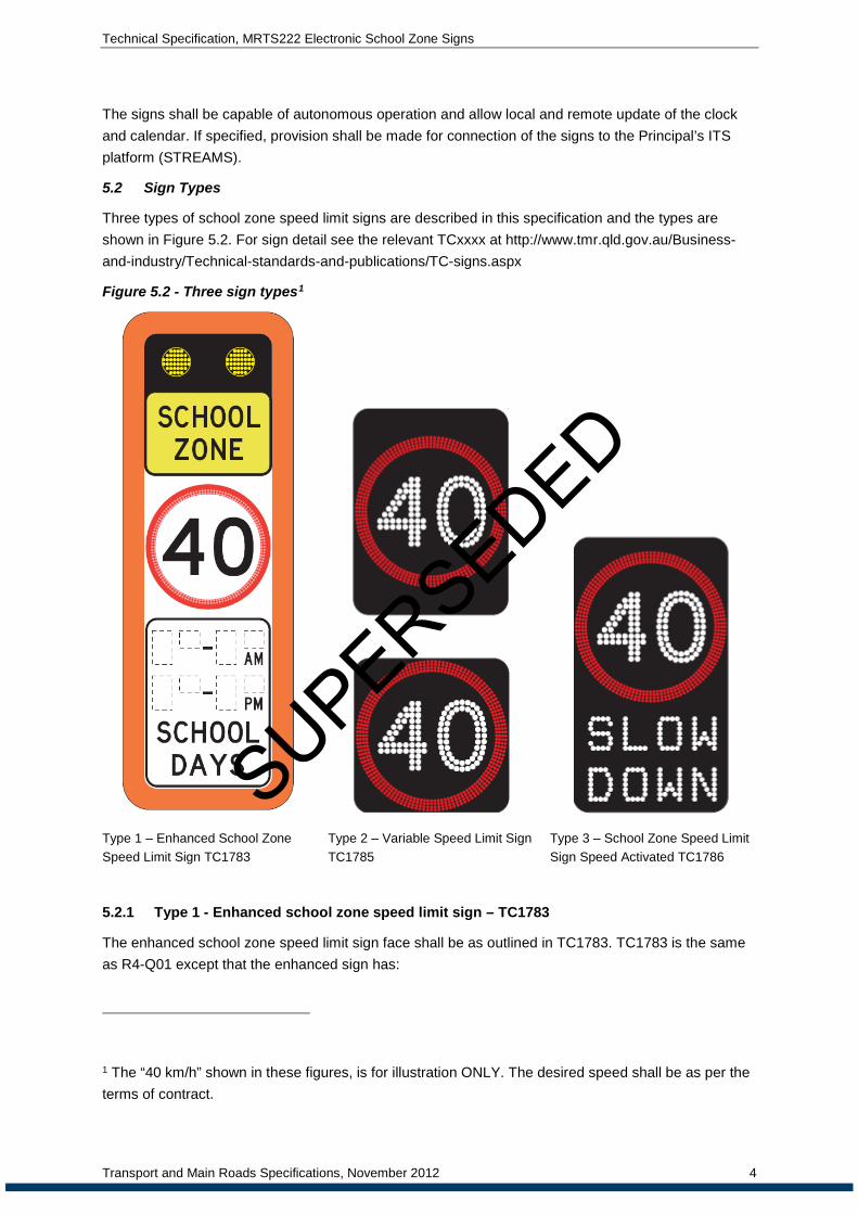
Three types of school zone speed limit signs are described in this specification and the types are shown in Figure 5.2. For sign detail see the relevant TCxxxx at http://www.tmr.qld.gov.au/Business-and-industry/Technical-standards-and-publications/TC-signs.aspx
Figure 5.2 - Three sign types1
Type 1 – Enhanced School Zone Speed Limit Sign TC1783
Type 2 – Variable Speed Limit Sign TC1785
Type 3 – School Zone Speed Limit Sign Speed Activated TC1786
5.2.1 Type 1 - Enhanced school zone speed limit sign – TC1783
The enhanced school zone speed limit sign face shall be as outlined in TC1783. TC1783 is the same as R4-Q01 except that the enhanced sign has:
1 The “40 km/h” shown in these figures, is for illustration ONLY. The desired speed shall be as per the terms of contract.
Transport and Main Roads Specifications, November 2012 4
SUPERSEDED
Technical Specification, MRTS222 Electronic School Zone Signs
• a set of flashing lights or wig-wags above the “school zone” wording, and
• has one or more LED based rings located within the confines of the static annulus.
The annulus and wig-wag LEDs shall be red and yellow respectively.
The annulus and wig-wags shall flash continuously during the designated school zone periods and at no other times. The flash rate of the annulus and the wig-wags shall be the same, meaning that the annulus will flash simultaneously with one of the wig-wag LED lanterns. The wig-wags shall flash alternately.
5.2.2 Type 2 – Variable speed limit sign – TC1785
Type 2 signs shall only be installed as a supplement to static signage. They must be installed in conjunction with a static R4-Q01 sign, as detailed in the School Environment Safety Technical Guidelines.
The face of the sign shall comply with the speed restriction sign (R4-1 specified in the MUTCD), except:
• with illuminated white numerals within an illuminated red annulus on a matt black background as shown in Figure 5.2; and
• the sign enclosure may be square but the active display elements shall still satisfy dimensions specified in R4-1.
The sign display shall remain blank at all times except during the designated school zone periods. During the school zone period, all the pixels constituting the numerals and the annulus outermost ring(s) shall be activated. Selected inner rings of the annulus shall flash continuously until expiry of the school zone time period. When this sign is used at school zones the sign shall only be capable of displaying the designated school zone speed limit.
5.2.3 Type 3 – School zone speed limit sign speed activated – TC1786
Type 3 signs shall only be installed as a supplement to static signage. They must be installed in conjunction with a static R4-Q01 sign, as detailed in the School Environment Safety Technical Guidelines.
The vehicle speed activated sign face shall be as outlined in TC1786.
The sign is similar to the Type 2 sign but in addition has the words “slow down” below the annulus.
The sign shall remain blank and disabled at all times outside the designated school zone periods. The display will only be enabled during the designated school zone periods but will remain blank unless a vehicle travelling above a set speed in the school zone is registered. The set detection speed shall be a configurable parameter of at least 10 km/h above the speed limit in 1 km/h increments. In this case, all pixels constituting annulus, the numerals and the words “slow down” shall switch on simultaneously. The sign display shall remain active for a set duration once activated. The sign shall remain active while the approaching vehicle remains at or over the speed threshold.
Vehicle speed detection shall be through use of a radar unit. The radar unit shall be mounted such that it is vandal proof and able to be aimed in different directions independently of the sign face. Speed threshold settings, detection distance and range of the radar unit shall be configurable values adjusted to suit the intended location of the sign. Where the carriageway at the school zone has more
Transport and Main Roads Specifications, November 2012 5
SUPERSEDED

Technical Specification, MRTS222 Electronic School Zone Signs
than one lane, the radar unit shall be capable of detecting approaching vehicles (including motorcycles and the like) in all lanes.
6 Mechanical & physical requirements
6.1 General
The signs shall comply with the requirements of MRTS14A and the Design Guidelines for Roadside Signs.
Where required, pits and conduits to accommodate power and communication cables shall be supplied and installed according to the requirements of MRTS91.
The mechanical and physical requirements defined in MRTS201 apply to this specification. Additional mechanical and physical requirements for equipment provided under this specification are described below.
The materials and methods of construction of the materials, equipment and enclosures shall be such that they have the strength and durability to withstand expected conditions of transportation, installation, and operation when installed in the intended environment.
The equipment and enclosures shall be of suitable design to protect against vandalism, and prevent infestation by vermin. Ingress protection (IP) rating for enclosures shall be no less than IP55 as defined in AS 60529. This includes all cable penetrations and equipment that may be located external to the enclosure. Physical LED protection shall be such that optical performance of the sign is unaffected. The signs shall be fitted with anti vandal features to reduce and deter vandalism to the sign and solar panel.
For Type 1 signs, the sign face material shall be aluminium. The flashing light assembly and accessories shall not cause the sign face to warp. The diameters of the flashing lanterns associated with each sign of sizes A, B or C, shall be in accordance with TC1783.
If LEDs are used for the flashing lights, the luminance of the LEDs, when measured under laboratory conditions shall comply with the requirements of Table 8.2.
6.2 Environmental conditions
The signs shall be capable of continuous, normal operation in the conditions described in MRTS201.
6.3 Sign placement
Sign placement shall be as directed by the Principal in accordance with requirements of the School Environmental and Safety Guidelines and the MUTCD. In addition, placement of Type 3 signs shall be such that sighting distance requirements and the distance to allow the proper function of the radar unit are met.
6.4 Sign enclosures
Associated sign control electronics shall be housed in an enclosure and in a manner which allows access for maintenance. Doors shall be capable of being hinged from either the left or right, but unless specified otherwise, shall be hinged from the left. The enclosure shall be fitted with a door switch to indicate if the enclosure door is open or improperly closed. All doors accessible to the public shall be lockable.
Transport and Main Roads Specifications, November 2012 6
SUPERSEDED

Technical Specification, MRTS222 Electronic School Zone Signs
Venting and air circulation arrangements shall be such that the thermal ratings of the electronics are not exceeded. Use of filters and forced cooling such as by use of fans is not allowed. Peltier devices or other similar means may be used for moisture control. Door seals are to ensure sustained ingress protection for the service life of the sign.
6.5 Design life
Unless otherwise specified, the design life of components shall be as follows;
• LEDs/pixels: a minimum of 10 years
• door switch: 50 000 operations
• other electrical systems: a minimum of 10 years
• sign enclosure: a minimum of 20 years
• structural supports: a minimum of 40 years.
6.6 Design loads
Static and wind design loads shall be in accordance with AS 1170.1 and AS 1170.2.
6.7 Location of mounting structure
Each sign and associated equipment shall be capable of being pole mounted.
Depending upon the road side safety assessment the system may use a separate support pole for the PV modules from that supporting the sign.
Frangible post or slip base construction may be used in high speed environments. The decision to use slip base or frangible posts shall be made by an Engineer with the appropriate RPEQ qualification.
Mounting hardware shall provide means to adjust the vertical and/or horizontal alignment of each sign and solar panel(s) during commissioning and subsequent maintenance activities.
Solar module(s) shall be mounted above the top of the sign at a height of no less than 4.5 metres. The solar module angle of elevation shall be suitably adjusted in order to optimise performance at the latitude where the sign is to be installed. The design of the solar modules shall include a deterrent mechanism for stopping birds from resting on the solar module structure. The solar module and mounting structure shall be fitted with anti-vandal features.
Unless otherwise specified the pole material and galvanised finish shall be as per MRTS94 and its referenced documents. Poles shall be designed and approved by a structural RPEQ. All footings shall be consistent with MRTS92 but shall be designed and approved by a structural RPEQ.
There shall be a fitting which allows the swivel adjustment of the azimuth about the vertical of 360° without stops. The swivel point shall be designed and fitted with a method which will stop the subsequent rotation of the solar PV module.
The location and type of mounting structure to be provided for each sign and solar panel shall be shown on the design documentation.
Final footing, support structure design and locations as shown in design documentation, shall be submitted to the Principal’s representative for acceptance before fabrication. Hold Point 3
6.8 Telecommunications field cabinets
Unless otherwise specified, no telecommunication field cabinets are required.
Transport and Main Roads Specifications, November 2012 7
SUPERSEDED

Technical Specification, MRTS222 Electronic School Zone Signs
If specified, provision for connection to field cabinets shall be made by way of ducts and pits if so specified in the design documents. Pits and ducts shall be installed in accordance with MRTS91.
6.9 Marking
Each sign shall be durably marked internally to show sign type, serial number, date of manufacture A-Tick and/or C-Tick compliance, and firmware release version. The details shall allow traceability of the sign manufacture according to the Contractor’s quality system.
The rear of each sign shall be affixed with a unique identification number as nominated by the Principal and a phone number to call in the event of a fault or damage to the sign. The label shall be designed to last 10 years in the range of environmental conditions described in MRTS201. The label shall be clearly legible from 1.5 meters above ground level, a distance of 5 meters from the base of the sign.
7 Operational requirements of sign displays
7.1 General
The operational requirements defined in MRTS201 apply to this specification. Additional operational requirements for equipment provided under this specification are described below.
The apparent width of all displayed elements including text shall match the respective sign display defined in the MUTCD. The minimum legibility (sight) distance shall be sufficient for both the respective school zone speed and the default speed limit before the sign.
The sign shall display only the regulatory speed applicable during the school zone designated time period.
The calendar function shall be able to be programmed three years in advance. The school days shall be confirmed during the commissioning activities and retained as part of the non-volatile information stored in the sign.
7.2 Display technology
The display technology shall be light emitting diode (LED). To achieve the required sign luminance levels, the display pixels may be formed by arranging one or more LEDs in a cluster.
7.3 LED output
Each individual LED shall be driven with a continuous current with no peak and/or magnitudes exceeding 70% of the LED manufacturer's maximum continuous rating. For LEDs in a 5 mm or smaller diameter package, peak magnitudes of the LED current shall not exceed 20 mA.
7.4 Character formats
Only fonts accepted by the Principal’s Representative shall be used.
Numerals for Type 1 signs shall be as per R4-Q01
Numerals for Type 2 and 3 signs shall meet the fonts defined for use on a Regulatory Sign R4-1.
The annulus shall not be less in size than that required for an equivalent static sign.
7.5 Sign display
There shall be no discernable flickering of the displayed numerals or static portion of the annulus. Background flickering as a result of checking the ‘on’ and ‘off’ pixel status shall not be visible.
Transport and Main Roads Specifications, November 2012 8
SUPERSEDED

Technical Specification, MRTS222 Electronic School Zone Signs
7.6 Display colour
For Type 1 signs LEDs for the wig-wags shall be yellow in colour and LEDs for the annulus shall be red.
For Type 2 and 3 signs, the display shall be generated by red and white LED's on a matte black background.
The red, yellow and white colours for all sign types shall fall within the chromaticity coordinates specified in Section 2 of AS/NZS 2144:2002.
7.7 Default display
Facilities shall be included to detect failures within the display control system with the sign blanking the display when major faults are detected.
In the case of Type 1 signs, loss of 20% of the annulus LEDs or 20% of either of the wig-wag lantern LEDs shall cause the sign to blank.
For Type 2 and 3 signs the sign shall be able to detect LED failure even if the LEDs may be required to be ‘off’ at the time of the periodic check. The display shall be blanked upon failure of 2% of contiguous pixels for the displayed image or failure of more than 20% of total LEDs.
The sign shall blank the display for the following conditions:
• a sign processor fault
• corruption of the calendar, time function, and
• failure of 20% of LEDs of the annulus and/or any digit or when displayed digit cannot be readily recognised.
The sign shall also blank whenever the battery voltage is lower than the set threshold. However, upon battery recharge, the sign shall resume normal operation.
Ambient light sensor failure should not result in blanking of the display. Upon failure of the ambient light sensor, the sign should fall back to time-of-day brightness levels.
7.8 Event logging
If required, the sign shall log all operational and fault events, including the date and time that the event occurs. Details of these events shall be available via the Remote Sign Management System. The logging capacity shall be such that the logged data is of a minimum of one month duration. These events include, but are not limited to:
• activation of the school zone period (all signs)
• activation of display during school zone period (Type 3 sign)
• speed data (Type 3 signs) with adjustable bins where minimum bin width is 1 km/h
• Lower Energy Alarm (sign will not work in 24 hours if the battery does not receive charge in that time)
• loss of power (main and auxiliary)
• power restoration (main and auxiliary)
• high or low battery voltage occurrence
Transport and Main Roads Specifications, November 2012 9
SUPERSEDED

Technical Specification, MRTS222 Electronic School Zone Signs
• door opening
• Daily Power Consumption
• failure to communicate with the remote control centre
• LED failure
• light sensor failure
• dimming level
• loss of solar module
• high enclosure temperature
• local or remote connection, commencement and termination
Type 3 signs shall store in non-volatile memory:
• aggregates of the total vehicle activations per day
• Minimum Speed
• Maximum Speed
• 85th percentile speed (the speed at which 85% of the traffic is travelling)
• Daily Average Speed (Morning, Afternoon, Combined)
Logs shall be recorded in Australia Eastern Standard Time (AEST)
The sign shall also log the sign enclosure temperature each minute.
7.9 Red annulus
The annulus for the Type 1 sign shall comply with the requirements of TC1783.
In the case of Type 2 and Type 3 signs, the red annulus shall consist of suitably constructed, evenly spaced pixel rings with at least three pixel rings.
For Type 2 signs, all LEDs shall be active during the designated school zone periods.
For Type 3 signs, LEDs will only be enabled during the designated school zone periods but will remain blank and become activated only when a vehicle travelling above a set speed in the school zone is registered. When activated by a speeding vehicle, the LEDs of the annulus, the numerals and the "Slow Down" message shall not flash, but shall remain ON for a duration that would be visible to the speeding motorist for at least three consecutive seconds.
The annulus rings in all cases shall be constructed so that LEDs connected in series are separated by at least 3 LEDs from other circuits.
7.10 Flashing display elements
The flash rate for elements of the sign that are required to flash shall be configurable and shall initially be set to 50/50 (lit/unlit) with a cycle time of 1 second.
7.11 Conspicuity devices
No conspicuity devices or lanterns are required for the Type 2 and 3 signs. However, the signs shall allow conspicuity devices to be added in future if desired.
Transport and Main Roads Specifications, November 2012 10
SUPERSEDED

Technical Specification, MRTS222 Electronic School Zone Signs
7.12 Internal Clock
The sign shall be provided with a 24 hour internal clock. The clock shall be able to be synchronised with the TMS system clock or other appropriate time source as determined by the Principal. Time error shall be no more than 1 second over a period of 1 week.
7.13 Local facility switch
Where specified, a 3-position key operated facility switch that complies with MRTS201, shall be provided to enable selection of the following 3 display functions:
• off – display blank; control via all communications ports inhibited; status and diagnostic commands via all communications ports remain functional
• test mode – display active; control via all communications ports inhibited; status and diagnostic commands via all communications ports remain functional, and
• normal – display active; displayed message selected via the maintenance communications port and/or the control communications port.
7.14 Radar unit – Type 3 signs
Radar detection shall comply with the requirements of AS 2898.
The radar unit shall be directional and detect only approaching vehicles. The radar unit shall be able to detect vehicles travelling at speeds ranging from 30 km/h to 160 km/h. Detection range shall be adjustable between 50 m and 100 m. Speed detection accuracy shall be better than 3%.
The radar unit shall be adjustable such that there is no interference with other radar units within the same carriageway.
8 Optical performance
8.1 Test procedures
The optical performance for all sign types shall be determined by measurement under laboratory conditions of the parameters listed in Table 8.2:
• minimum luminance ratio
• minimum and maximum luminance and luminous intensity uniformity, and
• colour as per AS/NZS 2144.
The performance of the sign displays shall meet or exceed the parameters listed in Table 8.2. Witness Point
8.2 Luminance
The luminance of the LEDs, when measured under laboratory conditions shall comply with the requirements of Table 8.2.
Transport and Main Roads Specifications, November 2012 11
SUPERSEDED

Technical Specification, MRTS222 Electronic School Zone Signs
Table 8.2 - LED performance parameters
Sign Illuminance
Level (lx)
White and Yellow Red
Minimum Luminance
Ratio
Luminance (Cd/m2) Minimum Luminance
Ratio
Luminance (Cd/m2)
Min. Max. Min. Max.
40,000 10 6,200 120,000 5 2,800 60,000
4,000 10 1,100 21,000 5 500 10,000
400 10 300 3,700 5 200 2,700
8.3 LED intensity control
The LED intensity must be controlled to provide constant apparent brightness and maximum legibility distance for the range of the ambient light under which the sign must operate.
The levels of brightness, the number of light sensors, and the automatic dimming control functionality shall be in accordance with the LED intensity control requirements in AS 5156.
8.4 Luminance intensity half angle
The luminance intensity half angle shall be no less than 10 degrees.
8.5 Sun phantom
The effect of sunlight or other light sources shining on the optical elements shall be controlled such that inactive pixels do not appear active.
For Type 1 signs, provision shall be made for each lantern to be fitted with a visor to minimize sun-phantom and veiling illuminance effects or to reduce the possibility of a flashing signal being seen by traffic for which it is not intended.
The visor shall be sufficiently rigid to withstand distortion due to wind and extreme temperatures.
The interior surface of visors shall be finished so as to minimize reflections of the illuminated signal.
9 Sign control system
The control system requirements defined in MRTS201 apply to this specification. Additional sign control system requirements for equipment provided under this specification are described below.
9.1 General
The sign shall be capable of autonomous operation and allow local as well as remote access by diagnostic software and remote sign management software respectively. Each sign shall be uniquely identifiable electronically and shall be able to create a character string for use by the remote sign management software for this purpose.
Type 2 and 3 signs shall be able to vary the display brightness based on the output of the light sensor(s) connected to it. LED intensity control shall allow signs located on opposite sides of the carriageway to appear to have the same brightness.
9.2 Local control
The sign shall allow local control via a maintenance communications port using a laptop or a handheld device. Local control shall be gained using the diagnostic software. The system shall provide secure access to the signs to prevent unauthorised access to the signs.
Transport and Main Roads Specifications, November 2012 12
SUPERSEDED

Technical Specification, MRTS222 Electronic School Zone Signs
All sign diagnostics and configuration parameters able to be changed in the field shall be accessible when the sign is selected for local control. Remote control of the sign shall be disabled when the sign is selected for local control.
Disconnection of a laptop or handheld device shall cause the sign to revert to autonomous operation.
Ending of the maintenance session shall not require further interaction from the user, nor in anyway interrupt operation or require rebooting of the sign but immediately let the sign to revert to autonomous operation.
9.3 Sign remote control
Each sign shall be capable of being accessed remotely via a communications port. The sign shall allow remote updates of the calendar and synchronisation of time with the remote sign management software.
The sign shall be able to service requests by the remote sign management software including status reports and a log of events.
The sign shall be able to send unsolicited status message/alarm to the remote sign management software should an event occur that requires blanking of the display, annulus, numerals, or lanterns (wig wags).
The sign shall support remote connectivity via 3G, GPRS, ADSL or the Principal’s Telecommunications network. The sign shall have session management ability in order to protect the system against unauthorised access via the communication ports.
For Type 3 signs, the sign shall provide functionality for setting and changing the activation speed remotely. The sign shall also log speeds in bins. The bins shall be remotely adjustable with minimum bin widths of 1 km/h.
If specified, connection to the Principal’s network shall be made through a field processor that meets the requirements of MRTS232.
9.4 Sign management software
9.4.1 General
The software shall
• request passwords as part of the access and configuration authorisation process, and
• be compatible with Microsoft Windows® operating system environment, Windows XP, Windows Vista, Windows 7, and those industry standards current at the time of delivery. Any software provided shall be capable of operating on all such operating systems.
9.4.2 Diagnostic software
Diagnostic software shall be supplied with the sign for the purpose of sign configuration, commissioning and maintenance activities.
The diagnostic software shall fully implement all the sign functions required for the commissioning and maintenance of the sign. The diagnostic software shall be configured to request passwords as part of the sign access and configuration authorisation process.
If required, the diagnostic software shall be capable of suggesting ranges for each parameter as applicable when programming and not allow these limits to be exceeded. The diagnostic software
Transport and Main Roads Specifications, November 2012 13
SUPERSEDED

Technical Specification, MRTS222 Electronic School Zone Signs
shall have the capability to save and upload sign configurations to and from the respective school zone signs.
A desirable feature of the diagnostic software is a test program. This would facilitate testing of all the essential sign features including ability to activate, deactivate all pixels, select the number of the annulus inner rings to flash and to vary LED brightness.
The software shall allow the request of a full log of events and querying of events according to set criteria such as by sign(s), time, date, event type, or by duration.
9.4.3 Remote sign management system
It is intended that some of these signs will be connected to STREAMS in the future. As a result, detailed protocol information is to be provided in order to enable a STREAMS device driver to be written. The provision of this detailed protocol information may be used in the assessment of the product, both for tender evaluation purposes and for assessment of the product against this MRTS.
A remote Sign Management System must be supplied. The remote Sign Management Software should:
• detail the location and current status of all signs (operational, idle, fault condition)
• show signs on a map-based GUI
• implement multiple levels of user access such as
− Administrator
− maintenance
− standard user
− read only
• allow querying of events according to set criteria such as by sign(s), time, date, event type, or by duration
• poll the signs in the field every 24 hours to verify the communications link and that the sign has not failed. Failure of the sign management system to gain a response from the sign shall result in an event being logged in the system that highlights that the sign status is unknown and possibly failed or damaged
• allow updating and programming of each sign calendar; and
• backup/export/import of sign configuration and calendar.
9.5 Communication protocol
Communication with the sign shall be in accordance with a protocol accepted by the Principal’s Representative and the requirements of MRTS201.
10 Installation requirements
The installation requirements defined in MRTS201 apply to this specification. Additional installation requirements relevant under this specification are described below.
Transport and Main Roads Specifications, November 2012 14
SUPERSEDED

Technical Specification, MRTS222 Electronic School Zone Signs
a) the general layout, positions, reduced level for the footing (where applicable), and speed zones for the sign and details of the barrier and other mounting requirements shall be as shown on the design documentation
b) the position of in-ground mounting structures shall comply with the requirements of the MUTCD
c) the positioning of sign shall provide sight distances as described in the TRUM Manual; and
d) the sign location shall be verified by site inspection and shall be shown on the design documentation. The design documentation shall be submitted to the Verifier not less than seven days prior to the commencement of civil works for the sign foundations. Milestone
Before installation, the Contractor shall confirm the final sign location and the type, location and positioning of the mounting arrangements and/or protection barrier as shown in the design documentation to the Verifier.
11 Environmental
The environmental requirements defined in MRTS201 apply to this specification.
12 Electrical
12.1 General
Options to energize the sign shall include Mains power and solar power. The electrical requirements defined in MRTS201 Clause 10, apply to this specification. Additional solar power requirements relevant under this specification are described below.
The sign shall be able to operate normally for voltage variation of between -13% and +25% of normal supply voltage. Battery back-up shall be provided for the real time clock and processor to allow orderly power down in the case of loss of power supply.
Power supply and control wiring connection/disconnection shall be designed without requirement for personnel to be holders of an electrical licence to perform this task. This will generally require the use of modular type connections.
Electrical Protection, Switching and Isolation and Lightning Protection shall be provided in accordance with AS 4509.2. High Rupture Capacity (HRC) fuses only shall be used for circuit protection. The switchboard shall be labelled with nominal voltage and current, DC or AC as well as the requirements of Fire Emergency Information required by AS 5033.
An electrical wiring diagram shall be provided in each enclosure, with details specific to each installation.
Detailed designs of the electrical wiring including the solar power and charging assembly shall be reviewed and signed by the Contractor’s RPEQ. They shall then be submitted and approved by the Principal or their delegate for verification and acceptance.
12.2 Solar power requirements
The total warranty for the solar power system shall be at least five years.
The solar power system shall be capable of operating the sign autonomously without recharge for a minimum period of seven days throughout the entire warranty period.
Transport and Main Roads Specifications, November 2012 15
SUPERSEDED

Technical Specification, MRTS222 Electronic School Zone Signs
12.2.1 Batteries and capacitors
The selection of the batteries shall be consistent with AS 4086.1 and subject to the following additional conditions.
• the Secondary Battery technology shall have a high cycle life (>2000) and of a low-maintenance type
• the battery must be able to handle high levels of Depth of Discharge (DOD)
• the battery shall be of the type suitable for charging by solar cells, and
• Batteries with liquid electrolytes shall NOT be used.
Batteries (and capacitors) shall be installed to minimize risk of
• impact by a motor vehicle
• theft or vandalism, and
• explosion.
12.2.2 PV module
The choice, configuration, installation and testing of PV modules shall be consistent with AS 4509.1, AS 4509.2 and AS/NZS 5033.
All PV module fittings and adjustments shall be designed, manufactured and tested with appropriate theft prevention methods.
Solar modules shall have a deterrent mechanism for stopping birds from resting on the module.
13 ITS network telecommunications
The telecommunications requirements defined in MRTS201 apply to this specification.
14 Testing & commissioning
14.1 General
The testing and commissioning requirements defined in MRTS201 apply to this specification. Additional testing and commissioning requirements relevant under this specification are described below.
14.2 Test signs
Where specified in the design documentation, a test sign complete with accessories shall be provided to the Principal as part of the STREAMS Acceptance Test Plan (SAT) for testing of software components used to control signs within the ITS Network. Provision of the test sign will not be necessary if a test sign has previously passed a SAT or if the Principal specifies otherwise.
14.3 Factory acceptance tests
Compliance with the optical performance requirements shall be determined by measurement under laboratory conditions of the parameters listed in Table 8.2, as detailed in Clause 8 for each batch of signs provided by the contractor. Witness Point
Transport and Main Roads Specifications, November 2012 16
SUPERSEDED

Technical Specification, MRTS222 Electronic School Zone Signs
14.4 Site acceptance test
All equipment shall be subject to production testing and each commission sign shall be functionally tested before the handover to customer. The test shall, as a minimum, include the following procedures:
• simulation of all fault conditions, including:
− total power failure/sign knockdown
− removal of solar panel
− communications failure
− LED Fault; both annulus and wig-wags
• commissioning tests defined in AS 5033
The Contractor shall provide a test report with the results of the witnessed tests.
For single panel installations the open circuit voltage must be confirmed, when connected to the cable loom
14.5 System acceptance test
After all sites pass a site acceptance test, the system shall be tested, by visual verification of each sign site, during and outside school zone periods. The contractor shall verify the correct operation of each sign, with the parameters observed in sign management system.
14.6 Sign configuration
Setting of the time, calendar functions, and display duration and activation speed (for Type 3) shall be performed as part of the commissioning process. The Principal will provide the set speed for vehicle activation and the active display duration time.
15 Documentation
If required, the Contractor shall provide, with each sign, specific details and calculations of the battery size, solar panel size and battery charger/regulator. This documentation shall contain all the applicable elements provided in the worked example of Appendix A of AS 4509.2. The manufacturer specification sheet of the PV array, batteries and battery charger/regulator shall be provided.
An Operations and Maintenance Manual shall be provided with each sign.
The documentation requirements defined in MRTS201 apply to this specification
16 Training
The training requirements defined in MRTS201 apply to this specification.
17 Maintenance
The maintenance requirements defined in MRTS201 apply to this specification.
18 Handover
The handover requirements defined in MRTS201 apply to this specification.
Transport and Main Roads Specifications, November 2012 17
SUPERSEDED

SUPERSEDED