Embed Size (px)
Citation preview

MSC O N N E C T O R Saccording to MIL-C-5015
MS-6/0100

2
MS
Dimensions are mmSubject to changes
Contents
General Information ........................................ 2Shell Styles .................................................... 3Technical Data ................................................ 4Part number Explanation ................................ 5Contact Arrangements .................................... 6Wall Mounting Receptacle .............................. 17Cable Connecting Plug ....................................18Box Mounting Receptacle ............................... 19Straight Plug ................................................... 1990° Angle Plug .............................................. 20Straight Plug, CA-F Type ............................... 21Straight Plug, CA-E Type ............................... 22Through-Bulkhead ......................................... 22Accessories ................................................... 23Contacts ....................................................... 27Tooling ........................................................... 29Product Safety Information ........................... 30
Different Classes
Connector classes MS 3106F, MS 3106R andMS 3108R feature an O-ring under the couplingnut. It is missing on connectors class MS 3106Eand MS 3108E.
To reduce size and weight, connector classesMS 3100R, MS 3101R and MS 3106R have nocable strain relief. The 90° angle plug MS 3106Rhas no cable clamp and is suitable for hoseconnection. Strain relief for this connector hasto be ordered separately (see page 23). More-over, construction and materials used are identi-cal for all connector classes.
Different Designations
Connectors with MS designation conform toMIL-C-5015 in respect of dimensions and con-tact arrangements.
Deviations from this specification, e. g. crimpcontacts, other shell or contact finishes, aredesignated CA.
Introduction
This catalogue describes Cannon connectorsdesigned and manufactured to MIL-C-5015, themilitary specification covering MS electricalconnectors. These connectors were originallydesigned for aircraft, but are now widely used inmany other fields. They are particularly suitablefor commercial applications requiring low costand high reliability.
The design of connector classes MS-E, MS-F andMS-R conforms to MIL-C-5015 D. The new classF connectors supersede the previous class Econnectors. For new programs only class Fshould be ordered.The coupling measurementsas well as the dimensions of class MS-E, -F and-R are in accordance with the latest revision ofVG 0095342. Wall mount receptacle, box re-ceptacle, cable connector and straight plug havethe same coupling dimensions. This allowsmating of the different classes of these connec-tors.
The connectors of class E, F and R are designedto operate in extreme environmental conditions.These connectors are completely sealed towithstand moisture, condensation, vibration andflash-over. MS-F and MS-R connectors have aresilient grommet around each wire. This allowsthe wires to slide through the grommet with aminimum of friction. Yet when the ferrule issealed and the endbells are tightened, it providesperfect wire seal through a wide variety of wirediameters. This seal at the rear plus the interfacialseal at the front, effect a completely environmen-tal resistant assembly when the plug is matedto an F or R receptacle.
Design Features
Straight Plug (E- and F-Types) O RingMS-Fonly
Straight Plug (R-Type)
Bushing Endbell Ferrule Grommet Pin contacts Insulator Coupling Nut Barrel O Ring
MS
3
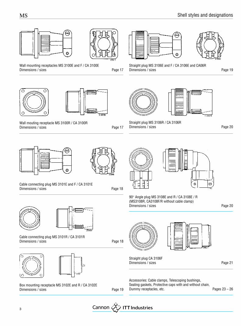
Wall mounting receptacles MS 3100E and F / CA 3100EDimensions / sizes Page 17
Wall mouting receptacle MS 3100R / CA 3100RDimensions / sizes Page 17
Cable connecting plug MS 3101E and F / CA 3101EDimensions / sizes Page 18
Cable connecting plug MS 3101R / CA 3101RDimensions / sizes Page 18
Box mounting receptacle MS 3102E and R / CA 3102EDimensions / sizes Page 19
Straight plug MS 3106E and F / CA 3106E and CA06RDimensions / sizes Page 19
Straight plug MS 3106R / CA 3106RDimensions / sizes Page 20
90° Angle plug MS 3108E and R / CA 3108E / R(MS3108R, CA3108F/R without cable clamp)Dimensions / sizes Page 20
Straight plug CA 3106FDimensions / sizes Page 21
Accessories: Cable clamps, Telescoping bushings,Sealing gaskets, Protective caps with and without chain,Dummy receptacles, etc. Pages 23 – 26
Shell styles and designations
4
MS
Dimensions are mmSubject to changes
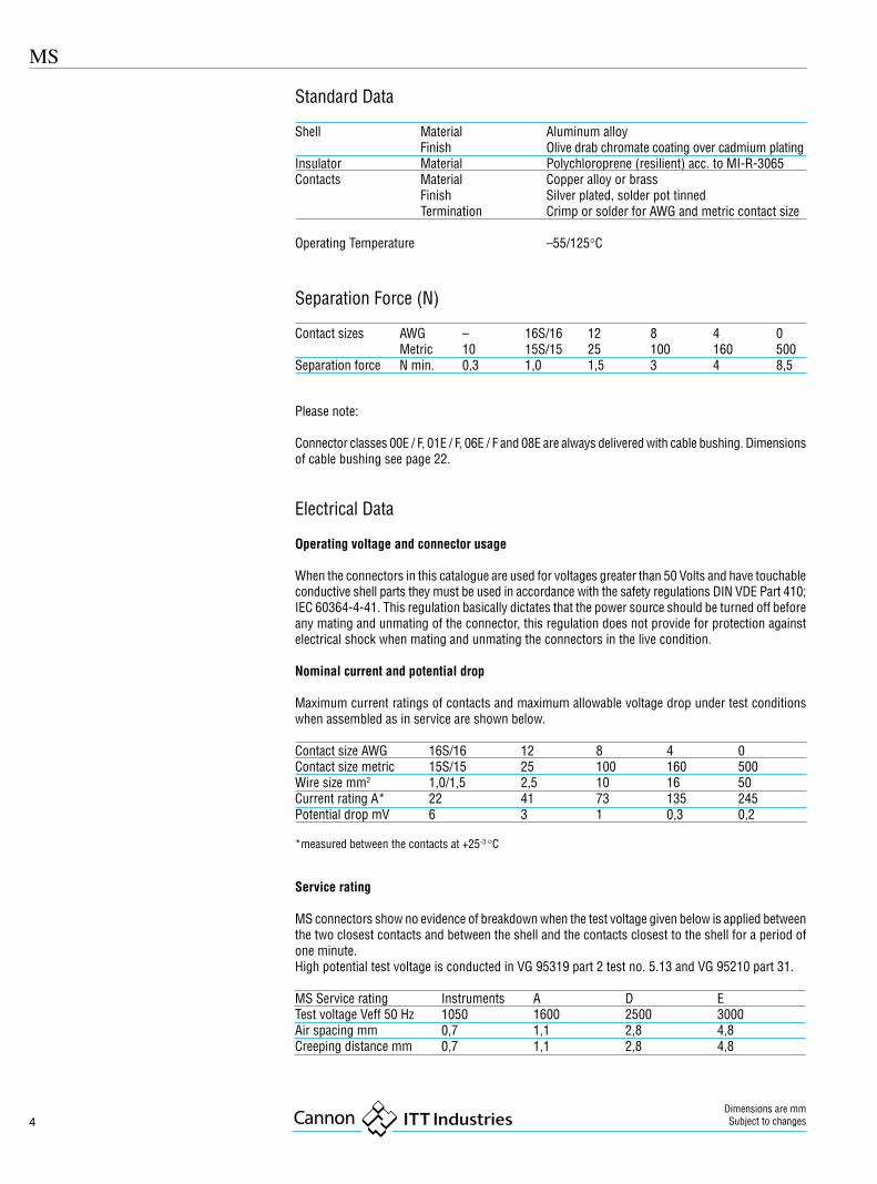
Standard Data
Shell Material Aluminum alloyFinish Olive drab chromate coating over cadmium plating
Insulator Material Polychloroprene (resilient) acc. to MI-R-3065Contacts Material Copper alloy or brass
Finish Silver plated, solder pot tinnedTermination Crimp or solder for AWG and metric contact size
Operating Temperature –55/125°C
Separation Force (N)
Contact sizes AWG – 16S/16 12 8 4 0Metric 10 15S/15 25 100 160 500
Separation force N min. 0,3 1,0 1,5 3 4 8,5
Please note:
Connector classes 00E / F, 01E / F, 06E / F and 08E are always delivered with cable bushing. Dimensionsof cable bushing see page 22.
Electrical Data
Operating voltage and connector usage
When the connectors in this catalogue are used for voltages greater than 50 Volts and have touchableconductive shell parts they must be used in accordance with the safety regulations DIN VDE Part 410;IEC 60364-4-41. This regulation basically dictates that the power source should be turned off beforeany mating and unmating of the connector, this regulation does not provide for protection againstelectrical shock when mating and unmating the connectors in the live condition.
Nominal current and potential drop
Maximum current ratings of contacts and maximum allowable voltage drop under test conditionswhen assembled as in service are shown below.
Contact size AWG 16S/16 12 8 4 0Contact size metric 15S/15 25 100 160 500Wire size mm2 1,0/1,5 2,5 10 16 50Current rating A* 22 41 73 135 245Potential drop mV 6 3 1 0,3 0,2
*measured between the contacts at +25-3 °C
Service rating
MS connectors show no evidence of breakdown when the test voltage given below is applied betweenthe two closest contacts and between the shell and the contacts closest to the shell for a period ofone minute.High potential test voltage is conducted in VG 95319 part 2 test no. 5.13 and VG 95210 part 31.
MS Service rating Instruments A D ETest voltage Veff 50 Hz 1050 1600 2500 3000Air spacing mm 0,7 1,1 2,8 4,8Creeping distance mm 0,7 1,1 2,8 4,8
MS
5
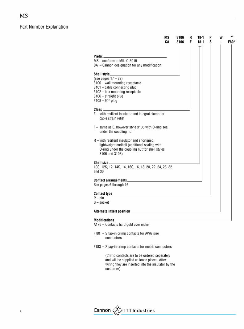
PrefixMS – conform to MIL-C-5015CA – Cannon designation for any modification
Shell style(see pages 17 – 22)3100 – wall mounting receptacle3101 – cable connecting plug3102 – box mounting receptacle3106 – straight plug3108 – 90° plug
ClassE – with resilient insulator and integral clamp for
cable strain relief
F – same as E, however style 3106 with O-ring sealunder the coupling nut
R – with resilient insulator and shortened,lightweight endbell (additional sealing withO-ring under the coupling nut for shell styles3106 and 3108)
Shell size10S, 12S, 12, 14S, 14, 16S, 16, 18, 20, 22, 24, 28, 32and 36
Contact arrangementsSee pages 6 through 16
Contact typeP – pinS – socket
Alternate insert position
ModificationsA176 – Contacts hard gold over nickel
F 80 – Snap-in crimp contacts for AWG sizeconductors
F183 – Snap-in crimp contacts for metric conductors
(Crimp contacts are to be ordered separatelyand will be supplied as loose pieces. Afterwiring they are inserted into the insulator by thecustomer)
MS 3106 R 18-1 P W * CA 3106 F 18-1 S - F80*
Part Number Explanation

6
MS
Dimensions are mmSubject to changes
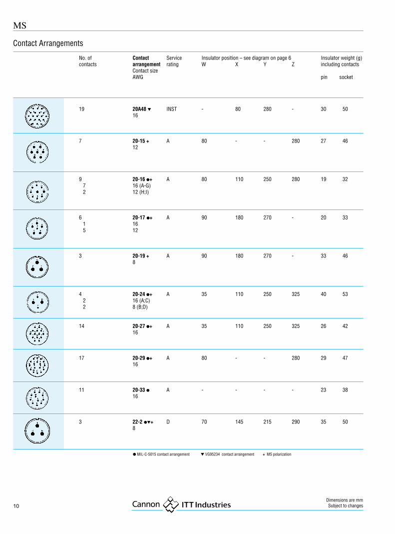
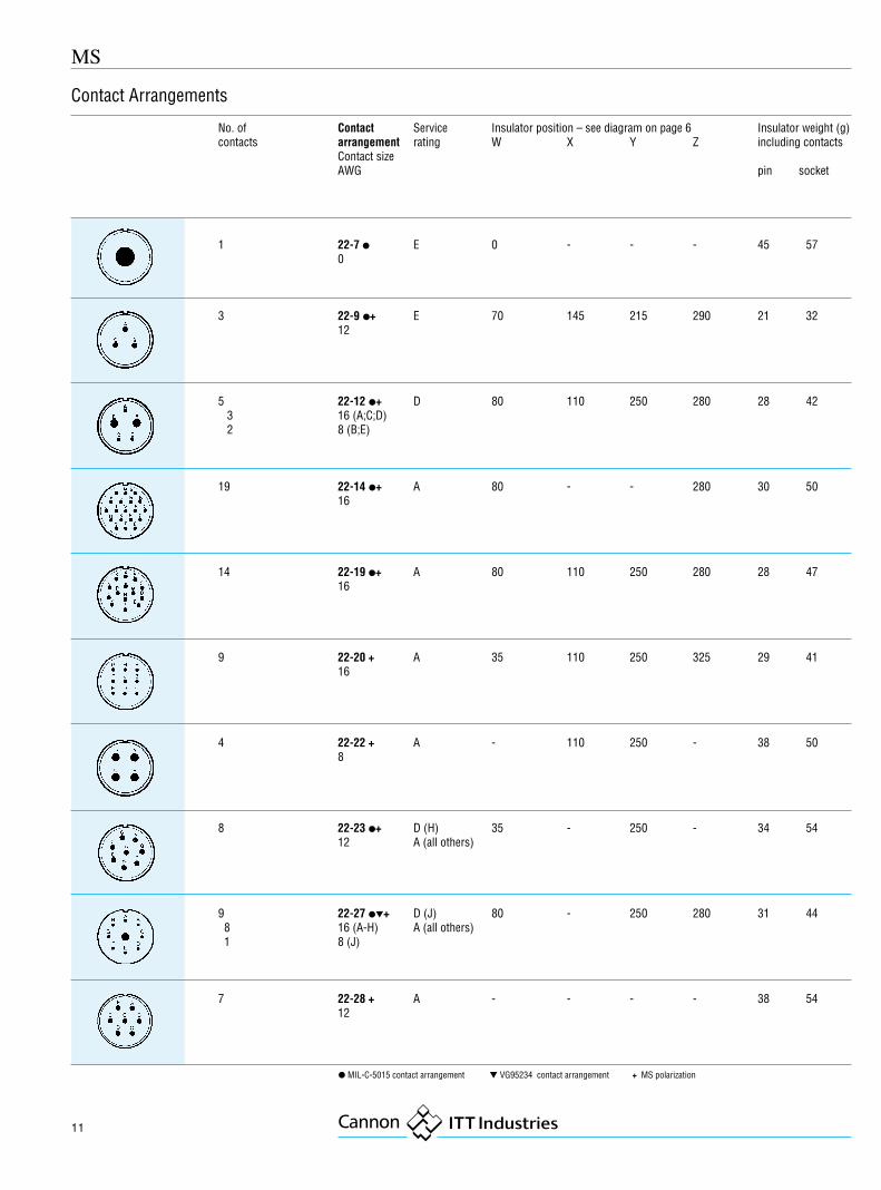
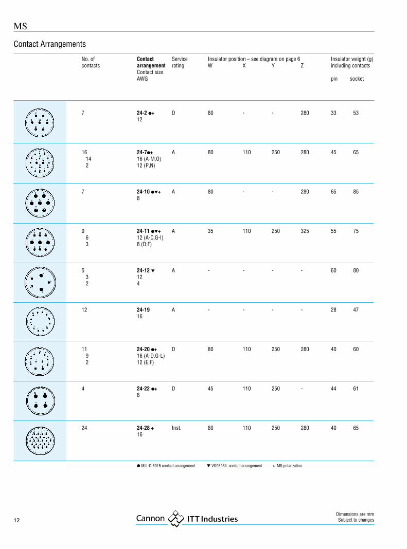
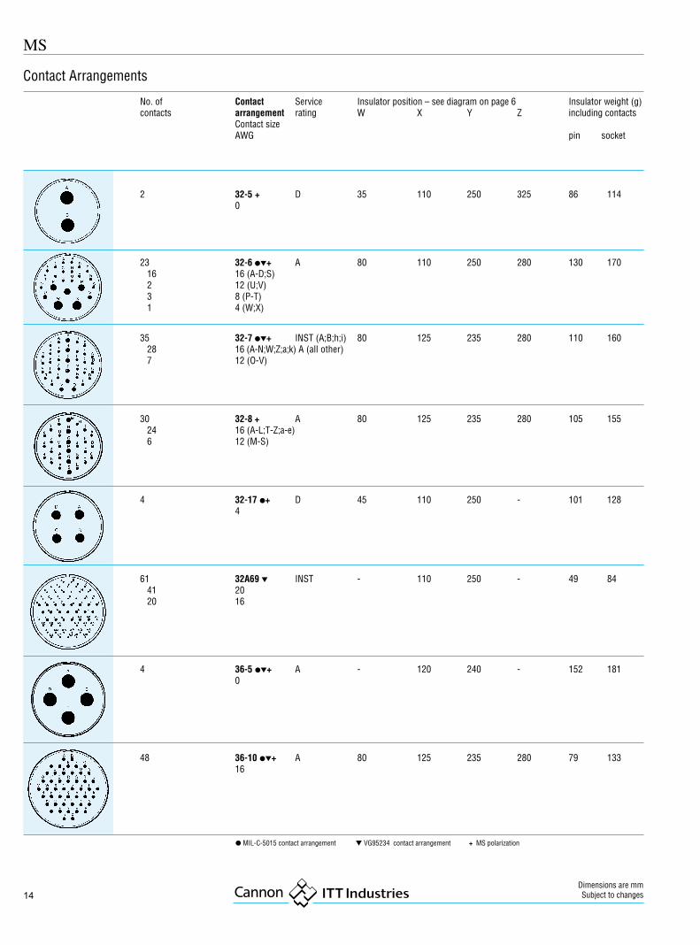
In the table on pages 7 – 14 the contact arran-gements are listed by shell sizes. The shell sizeand the contact arrangement number are givenin the designation printed in bold typefaces: thedigits following the dash are the contact arran-gement number (see Part Number Explanationon page 5).
Furthermore, the number of contacts and theAWG wire sizes are included in the table. Therecommended wire sizes are shown on this page,the electrical data on page 4.
Contact size Conductor size Insulation sizesfor solder contacts for crimp contacts (in mm) forAWG mm2 AWG conductor ∅ metric conductor ∅ AWG metric
mm mm2 mm contacts contacts– / 10 – – – – 0,75 1,0 1,0 - 1,4 – 2,0 - 2,516S/15S 16-22 1,2 - 0,4 16 1,25 - 1,7 1,0 - 1,7 1,25 - 1,7 1,63 - 3,3 2,2 - 2,816 / 15 16-22 1,2 - 0,4 16 1,25 - 1,7 1,0 - 1,5 1,25 - 1,7 1,63 - 3,3 2,2 - 2,812 / 15 12-14 3,5 - 2,0 12 1,95 - 2,2 2,5 1,95 - 2,2 2,9 - 4,3 3,1 - 3,58 / 100 8 - 10 8,5 - 4,5 8 4,0 - 4,5 10 4,3 - 4,8 2,9 - 6,4 5,9 - 6,54 / 160 4 - 6 21,5 - 13,5 4 6,0 - 6,9 16 5,2 - 6,0 7,0 - 9,4 7,1 - 7,70 / 500 0 - 2 53,0 - 33,5 0 10,6 - 11,5 50 9,6 - 10,7 10,6 - 14,0 12,1 - 12,8
Pin insert front view
The connectors are designed for individualwiring. Spray water and moisture resistance areonly guaranteed if wires according to MIL-W-5086, LN 9251 (for AWG diameters), TL 6145-009 and TL 6145-011 (for metric diameters) are
Wire Selection
Contact Arrangements
used. When using wires which do not cor-respond to these specifications the wire dia-meters and outer dimensions of the insulationindicated in below table have to be adhered to.
Alternate Insert PositionsAlternate insert positions can be offered to preventmismating of adjacent identic connectors.
The standard insert position is without designa-tion. The four alternate positions are designatedW, X, Y and Z (see diagram below).
Please note:All MS qualified insert positions are listed onpages 7 – 14. Other positions than normal arenot available from stock.
MS
7
Contact Arrangements
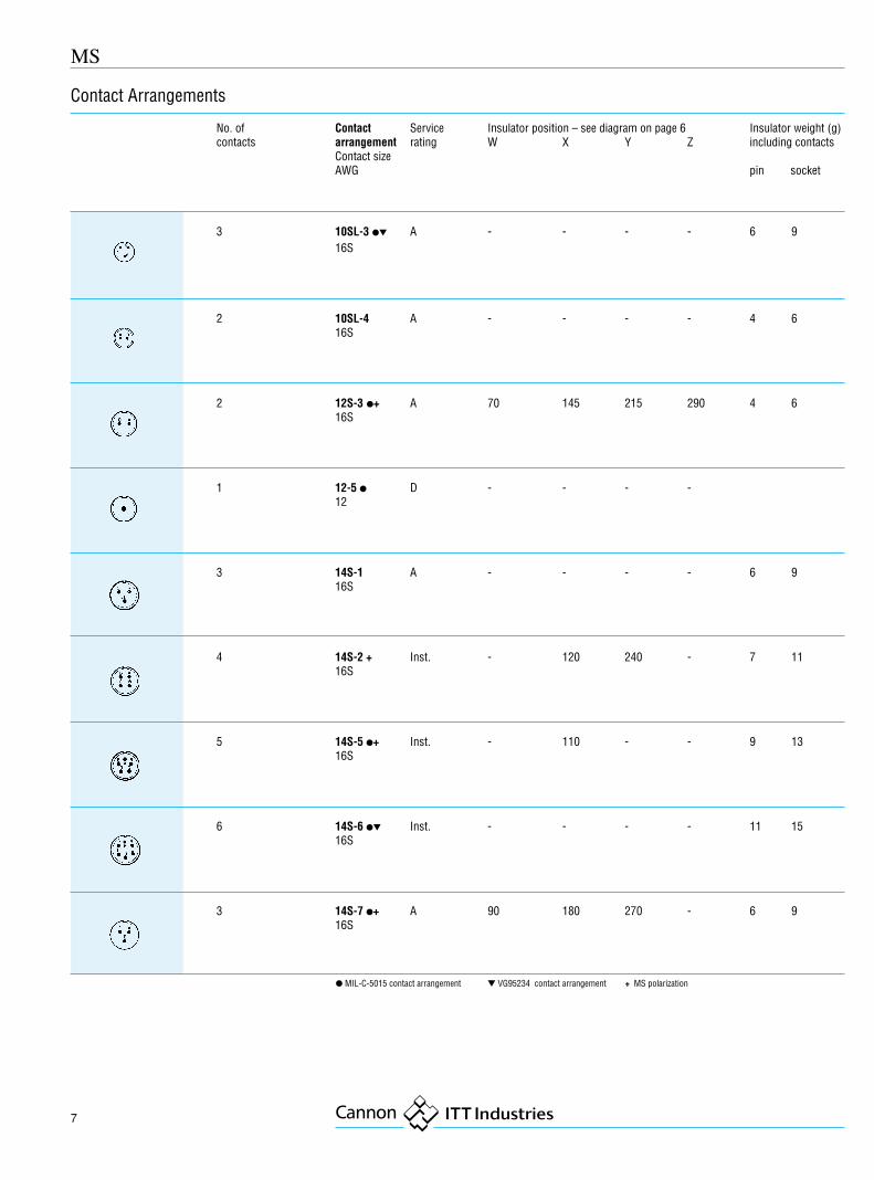
No. of Contact Service Insulator position – see diagram on page 6 Insulator weight (g)contacts arrangement rating W X Y Z including contacts
Contact sizeAWG pin socket
3 10SL-3 �� A - - - - 6 916S
2 10SL-4 A - - - - 4 616S
2 12S-3 �+ A 70 145 215 290 4 616S
1 12-5 � D - - - -12
3 14S-1 A - - - - 6 916S
4 14S-2 + Inst. - 120 240 - 7 1116S
5 14S-5 �+ Inst. - 110 - - 9 1316S
6 14S-6 �� Inst. - - - - 11 1516S
3 14S-7 �+ A 90 180 270 - 6 916S
� MIL-C-5015 contact arrangement � VG95234 contact arrangement + MS polarization
8
MS
Dimensions are mmSubject to changes
Contact Arrangements
Contact Arrangements
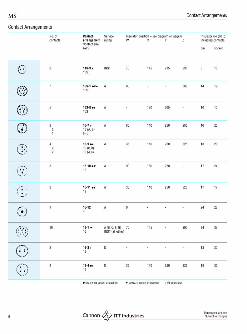
No. of Contact Service Insulator position – see diagram on page 6 Insulator weight (g)contacts arrangement rating W X Y Z including contacts
Contact sizeAWG pin socket
2 14S-9 + INST 70 145 215 290 5 1816S
7 16S-1 ��+ A 80 - - 280 14 1916S
5 16S-8 �+ A - 170 265 - 10 1516S
3 16-7 + A 80 110 250 280 16 25 2 16 (A, B) 1 8 (C)
4 16-9 �+ A 35 110 250 325 13 20 2 16 (B,D) 2 12 (A,C)
3 16-10 �� A 90 180 270 - 17 2412
2 16-11 �+ A 35 110 250 325 11 1712
1 16-12 A 0 - - - 24 284
10 18-1 �+ A (B, C, F, G) 70 145 - 290 24 3716 INST (all other)
2 18-3 + D - - - - 13 2212
4 18-4 �+ D 35 110 250 325 19 3016
� MIL-C-5015 contact arrangement � VG95234 contact arrangement + MS polarization
MS
9
Contact Arrangements
Contact Arrangements
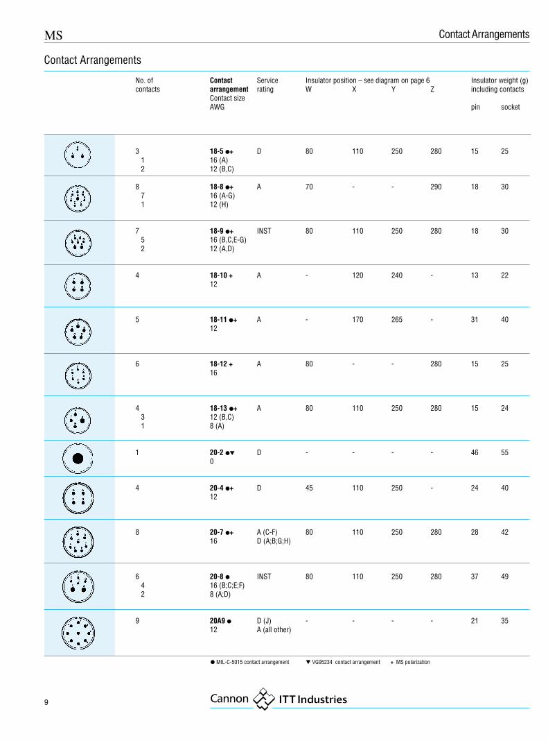
No. of Contact Service Insulator position – see diagram on page 6 Insulator weight (g)contacts arrangement rating W X Y Z including contacts
Contact sizeAWG pin socket
3 18-5 �+ D 80 110 250 280 15 25 1 16 (A) 2 12 (B,C)
8 18-8 �+ A 70 - - 290 18 30 7 16 (A-G) 1 12 (H)
7 18-9 �+ INST 80 110 250 280 18 30 5 16 (B,C,E-G) 2 12 (A,D)
4 18-10 + A - 120 240 - 13 2212
5 18-11 �+ A - 170 265 - 31 4012
6 18-12 + A 80 - - 280 15 2516
4 18-13 �+ A 80 110 250 280 15 24 3 12 (B,C) 1 8 (A)
1 20-2 �� D - - - - 46 550
4 20-4 �+ D 45 110 250 - 24 4012
8 20-7 �+ A (C-F) 80 110 250 280 28 4216 D (A;B;G;H)
6 20-8 � INST 80 110 250 280 37 49 4 16 (B;C;E;F) 2 8 (A;D)
9 20A9 � D (J) - - - - 21 3512 A (all other)
� MIL-C-5015 contact arrangement � VG95234 contact arrangement + MS polarization
10
MS
Dimensions are mmSubject to changes
Contact Arrangements
No. of Contact Service Insulator position – see diagram on page 6 Insulator weight (g)contacts arrangement rating W X Y Z including contacts
Contact sizeAWG pin socket
19 20A48 � INST - 80 280 - 30 5016
7 20-15 + A 80 - - 280 27 4612
9 20-16 �+ A 80 110 250 280 19 32 7 16 (A-G) 2 12 (H;I)
6 20-17 �+ A 90 180 270 - 20 33 1 16 5 12
3 20-19 + A 90 180 270 - 33 468
4 20-24 �+ A 35 110 250 325 40 53 2 16 (A;C) 2 8 (B;D)
14 20-27 �+ A 35 110 250 325 26 4216
17 20-29 �+ A 80 - - 280 29 4716
11 20-33 � A - - - - 23 3816
3 22-2 ��+ D 70 145 215 290 35 508
� MIL-C-5015 contact arrangement � VG95234 contact arrangement + MS polarization
MS
11
Contact Arrangements
No. of Contact Service Insulator position – see diagram on page 6 Insulator weight (g)contacts arrangement rating W X Y Z including contacts
Contact sizeAWG pin socket
1 22-7 � E 0 - - - 45 570
3 22-9 �+ E 70 145 215 290 21 3212
5 22-12 �+ D 80 110 250 280 28 42 3 16 (A;C;D) 2 8 (B;E)
19 22-14 �+ A 80 - - 280 30 5016
14 22-19 �+ A 80 110 250 280 28 4716
9 22-20 + A 35 110 250 325 29 4116
4 22-22 + A - 110 250 - 38 508
8 22-23 �+ D (H) 35 - 250 - 34 5412 A (all others)
9 22-27 ��+ D (J) 80 - 250 280 31 448 16 (A-H) A (all others)1 8 (J)
7 22-28 + A - - - - 38 5412
� MIL-C-5015 contact arrangement � VG95234 contact arrangement + MS polarization
12
MS
Dimensions are mmSubject to changes
Contact Arrangements
No. of Contact Service Insulator position – see diagram on page 6 Insulator weight (g)contacts arrangement rating W X Y Z including contacts
Contact sizeAWG pin socket
7 24-2 �+ D 80 - - 280 33 5312
16 24-7�+ A 80 110 250 280 45 65 14 16 (A-M,O) 2 12 (P,N)
7 24-10 ��+ A 80 - - 280 65 858
9 24-11 ��+ A 35 110 250 325 55 75 6 12 (A-C,G-I) 3 8 (D;F)
5 24-12 � A - - - - 60 80 3 12 2 4
12 24-19 A - - - - 28 4716
11 24-20 �+ D 80 110 250 280 40 60 9 16 (A-D,G-L) 2 12 (E;F)
4 24-22 �+ D 45 110 250 - 44 618
24 24-28 + Inst. 80 110 250 280 40 6516
� MIL-C-5015 contact arrangement � VG95234 contact arrangement + MS polarization

MS
13
Contact Arrangements
No. of Contact Service Insulator position – see diagram on page 6 Insulator weight (g)contacts arrangement rating W X Y Z including contacts
Contact sizeAWG pin socket
22 28-11 + A 80 110 250 280 65 110 18 16 (A-I,N-X) 4 12 (J-M)
26 28-12 �+ A 90 180 270 - 47 7716
35 28-15 + A 80 110 250 280 54 9016
14 28-20 �+ A 80 110 250 280 65 110 4 16 (K-N) 10 12 (A-J,P)
37 28-21 ��+ A 80 110 250 280 58 9316
9 28A16 A (e) - 100 260 - 85 135 5 16 (A;D-F;J) INST (all other) 4 4 (B;C;G;H)
28 28A63 � - - - - 85 135 9 12 A (e) 19 16 INST (all other)
5 32-1 ��+ E (A) 80 110 250 280 - - 3 12 (A, C, D) D (all other) 2 0 (B, E)
� MIL-C-5015 contact arrangement � VG95234 contact arrangement + MS polarization
14
MS
Dimensions are mmSubject to changes
Contact Arrangements
No. of Contact Service Insulator position – see diagram on page 6 Insulator weight (g)contacts arrangement rating W X Y Z including contacts
Contact sizeAWG pin socket
2 32-5 + D 35 110 250 325 86 1140
23 32-6 ��+ A 80 110 250 280 130 170 16 16 (A-D;S) 2 12 (U;V) 3 8 (P-T) 1 4 (W;X)
35 32-7 ��+ INST (A;B;h;i) 80 125 235 280 110 160 28 16 (A-N;W;Z;a;k) A (all other) 7 12 (O-V)
30 32-8 + A 80 125 235 280 105 155 24 16 (A-L;T-Z;a-e) 6 12 (M-S)
4 32-17 �+ D 45 110 250 - 101 1284
61 32A69 � INST - 110 250 - 49 84 41 20 20 16
4 36-5 ��+ A - 120 240 - 152 1810
48 36-10 ��+ A 80 125 235 280 79 13316
� MIL-C-5015 contact arrangement � VG95234 contact arrangement + MS polarization

MS
15
Contact No. of Wire size Amp. Service Weightarrange- contacts AWG mm2 group Polychloroprenement insert
lbs. gr.
Shell size 10S/10SL
10SL-3 3 16 1,5 22 A P.010 4S.017 8
10SL-4 2 16 1,5 22 A P.009 4S.014 6
Shell size 12/12
12S-3 2 16 1,5 22 A P.010 5S.016 7
12-5 1 12 2,5 41 D P.- -
Shell size 14/14S
14S-1 3 16 1,5 22 A P.- -S.- -
14S-2 4 16 1,5 22 Inst. P.019 9S.028 13
14S-5 5 16 1,5 22 Inst. P.017 8S.029 13
14S-6 6 16 1,5 22 Inst. P.031 15S.015 7
14S-7 3 16 1,5 22 A P.015 7S.024 11
14S-9 2 16 1,5 22 A P.013 6S.022 10
Shell size 16/16S
16S-1 7 16 1,5 22 A P.025 11S.042 19
16-7 1 8 10,0 73 A P.- -2 16 1,5 22 S.- -
16S-8 5 16 1,5 22 A P.023 10S.039 18
16S-9 5 16 1,5 22 A P.023 10S.039 18
16-9 2 12 2,5 41 A P.031 142 16 1,5 22 A S.044 20
16-10 3 12 2,5 41 A P.031 14S.047 21
16-11 2 12 2,5 41 A P.028 13S.042 19
16-12 1 4 16,0 135 A P.031 14S.047 21
Shell size 18
18-1 10 18 1,5 22 A (B,C,F,G) P.044 20Inst.(all others) S.058 26
18-3 2 12 2,5 41 D P.038 17S.057 26
18-4 4 16 1,5 22 D P.037 17S.053 24
Contact No. of Wire size Amp. Service Weightarrange- contacts AWG mm2 group Polychloroprenement insert
lbs. gr.
Shell size 18 (continued)
18-5 2 12 2,5 41 D P.040 181 16 1,5 22 S.059 27
18-6 1 4 16,0 13,5 D P.048 22S. - -
18-8 1 12 2,5 41 A P.044 207 16 1,5 22 S.062 28
18-9 2 12 2,5 4 Inst. P.045 205 16 1,5 22 S.062 28
18-10 4 12 2,5 41 A P.046 21S.067 30
18-11 5 12 2,5 41 A P.049 22S.071 32
18-12 6 16 1,5 22 A P.039 18S.054 24
18-13 1 8 10,0 73 A P.- -S.- -
Shell size 20
20-2 1 0 50 245 D P.092 41S.101 45
20-4 4 12 2,5 41 D P.057 26S.086 38
20-7 8 16 1,5 22 A(C,D,E,F) P.053 26D(A,B.H.G) S.076 34
20-15 7 12 2,5 41 A P.068 30S.100 45
20-16 2 12 2,5 41 A P.059 267 16 1,5 22 S.084 38
20-17 5 12 2,5 41 A P.068 311 16 1,5 22 S.098 38
20-19 3 8 10,0 73 A P.068 31S.091 41
20-24 2 8 10,0 73 A P.062 282 16 1,5 22 S.085 38
20-27 14 16 1,5 22 A P.062 28S.082 37
20-29 17 16 1,5 22 A P.065 29S.085 38
20-33 11 16 1,5 22 A P.057 25S.079 35
20A9 9 - 2,5 41 D for J P.020 9S.033 15
20A48 19 - 1,5 22 Inst. P .020S.036 16
20-8 4 16 1,5 22 Inst. P.059 262 8 10 73 S.080 36
Contact Arrangements
16
MS
Dimensions are mmSubject to changes
Contact No. of Wire size Amp. Service Weightarrange- contacts AWG mm2 group Polychloroprenement insert
lbs. gr.
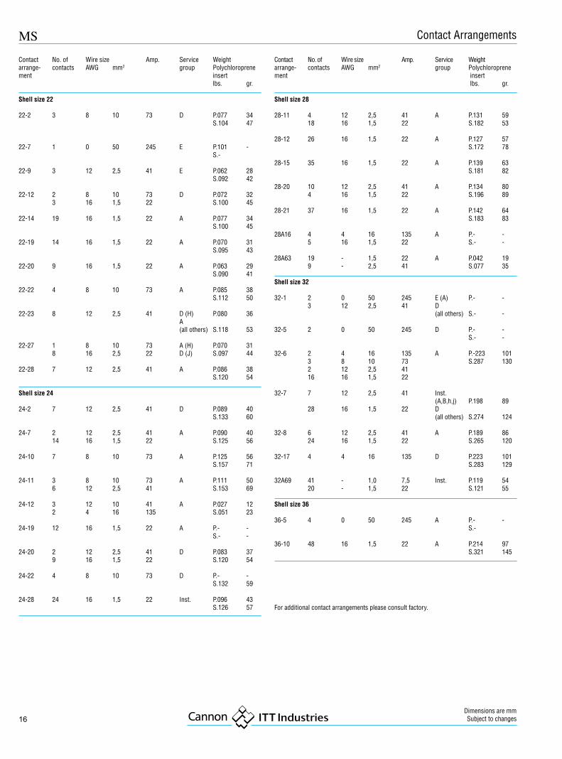
Shell size 22
22-2 3 8 10 73 D P.077 34S.104 47
22-7 1 0 50 245 E P.101 -S.-
22-9 3 12 2,5 41 E P.062 28S.092 42
22-12 2 8 10 73 D P.072 323 16 1,5 22 S.100 45
22-14 19 16 1,5 22 A P.077 34S.100 45
22-19 14 16 1,5 22 A P.070 31S.095 43
22-20 9 16 1,5 22 A P.063 29S.090 41
22-22 4 8 10 73 A P.085 38S.112 50
22-23 8 12 2,5 41 D (H) P.080 36A(all others) S.118 53
22-27 1 8 10 73 A (H) P.070 318 16 2,5 22 D (J) S.097 44
22-28 7 12 2,5 41 A P.086 38S.120 54
Shell size 24
24-2 7 12 2,5 41 D P.089 40S.133 60
24-7 2 12 2,5 41 A P.090 4014 16 1,5 22 S.125 56
24-10 7 8 10 73 A P.125 56S.157 71
24-11 3 8 10 73 A P.111 506 12 2,5 41 S.153 69
24-12 3 12 10 41 A P.027 122 4 16 135 S.051 23
24-19 12 16 1,5 22 A P.- -S.- -
24-20 2 12 2,5 41 D P.083 379 16 1,5 22 S.120 54
24-22 4 8 10 73 D P.- -S.132 59
24-28 24 16 1,5 22 Inst. P.096 43S.126 57
Contact No. of Wire size Amp. Service Weightarrange- contacts AWG mm2 group Polychloroprenement insert
lbs. gr.
Shell size 28
28-11 4 12 2,5 41 A P.131 5918 16 1,5 22 S.182 53
28-12 26 16 1,5 22 A P.127 57S.172 78
28-15 35 16 1,5 22 A P.139 63S.181 82
28-20 10 12 2,5 41 A P.134 804 16 1,5 22 S.196 89
28-21 37 16 1,5 22 A P.142 64S.183 83
28A16 4 4 16 135 A P.- -5 16 1,5 22 S.- -
28A63 19 - 1,5 22 A P.042 199 - 2,5 41 S.077 35
Shell size 32
32-1 2 0 50 245 E (A) P.- -3 12 2,5 41 D
(all others) S.- -
32-5 2 0 50 245 D P.- -S.- -
32-6 2 4 16 135 A P.-223 1013 8 10 73 S.287 1302 12 2,5 4116 16 1,5 22
32-7 7 12 2,5 41 Inst.(A,B,h,j) P.198 89
28 16 1,5 22 D(all others) S.274 124
32-8 6 12 2,5 41 A P.189 8624 16 1,5 22 S.265 120
32-17 4 4 16 135 D P.223 101S.283 129
32A69 41 - 1,0 7,5 Inst. P.119 5420 - 1,5 22 S.121 55
Shell size 36
36-5 4 0 50 245 A P.- -S.-
36-10 48 16 1,5 22 A P.214 97S.321 145
For additional contact arrangements please consult factory.
Contact Arrangements

MS
17
Order reference A B K L M P R S TPin insert* Thread min. ±0,7 max. +0,4 max. ±0,1 ±0,3 +0,2 / –0,1MS3100R-10SL-**P 5/8-24NEF-2A 9,5 3,0 45 14,2 24,4 18,2 25,4 3,1MS3100R-12S-**P 3/4-20UNEF-2A 9,5 3,0 45 14,2 24,4 20,6 28,0 3,1MS3100R14S-**P 7/8-20UNEF-2A 9,5 3,0 55 14,2 29,0 23,0 30,0 3,1MS3100R16S-**P 1 -20UNEF-2A 9,5 3,0 55 14,2 31,5 24,6 32,5 3,1MS3100R12-**P 3/4-20UNEF-2A 15,8 3,0 55 19,0 24,4 20,6 28,0 3,1MS3100R14-**P 7/8-20UNEF-2A 15,8 3,0 55 19,0 29,0 23,0 30,0 3,1MS3100R16-**P 1 -20UNEF-2A 15,8 3,0 55 19,0 31,5 24,6 32,5 3,1MS3100R18-**P 1 1/8-18NEF-2A 15,8 3,9 60 19,0 36,6 27,0 35,0 3,1MS3100R20-**P 1-1/4-18NEF-2A 15,8 3,9 60 19,0 39,7 29,4 38,0 3,1MS3100R22-**P 1-3/8-18NEF-2A 15,8 3,9 60 19,0 39,7 31,8 41,0 3,1MS3100R24-**P 1-1/2-18NEF-2A 15,8 3,9 60 20,6 47,4 34,9 44,5 3,7MS3100R26-**P 1-3/4-18 S-2A 15,8 3,9 67 20,6 47,4 39,7 50,8 3,7MS3100R32-**P 2 -18NS-2A 15,8 3,9 67 22,2 55,9 44,5 57,0 4,4MS3100R36-**P 2-1/4-16UN-2A 15,8 3,9 85 22,2 60,8 49,2 63,5 4,4
*For socket inserts substitute S for P **Add contact arrangement number (see pages 7 – 14)
MS3100R / CA3100R
The MS3100R receptacles feature a shorterand lightweight endbell and mate with 3106and 3108 plugs.
If crimp version is required please orderCA3100R...F80 or CA3100R...F183
Order reference A B E1) K L M R S V W TPin insert* Thread min. max. ±0,7 max. +0,4 ±0,1 ±0,3 max. max. +0,2 / –0,1MS3100E10SL-**P 5/8-24 EF-2A 9,5 6,5 3,0 60 14,2 18,2 25,4 22,7 27,0 3,1MS3100E-12S-**P 3/4-20UNEF-2A 9,5 6,5 3,0 60 14,2 20,6 28,0 22,7 27,0 3,1MS3100E14S-**P 1/8-20UNEF-2A 9,5 9,0 3,0 70 14,2 23,0 30,0 27,5 34,0 3,1MS3100E16S-**P 1 -20UNEF2A 9,5 11,0 3,0 70 14,2 24,6 32,5 30,0 38,0 3,1MS3100E12-**P 3/4-20UNEF-2A 15,8 6,5 3,0 70 19,0 20,6 28,0 22,7 27,0 3,1MS3100E14-**P 7/8-20UNEF-2A 15,8 9,0 3,0 70 19,0 23,0 30,0 27,5 34,0 3,1MS3100E16-**P 1 -20UNEF-2A 15,8 11,0 3,0 70 19,0 24,6 32,5 30,0 38,0 3,1MS3100E18-**P 1-1/8-18NEF-2A 15,8 14,2 3,9 77 19,0 27,0 35,0 32,2 40,5 3,1MS3100E20-**P 1-1/4-18NEF-2A 15,8 15,8 3,9 77 19,0 29,4 38,0 37,5 47,5 3,1MS3100E22-**P 1-3/8-18NEF-2A 15,8 15,8 3,0 77 19,0 31,8 41,0 37,5 47,5 3,1MS3100E24-**P 1-1/2-18NEF-2A 15,8 21,4 3,9 77 20,6 34,9 44,5 43,3 54,0 3,7MS3100E28-**P 1-3/4-18NS-2A 15,8 21,4 3,0 85 20,6 39,7 50,8 43,3 54,0 3,7MS3100E32-**P 1 -18NS-2A 15,8 26,7 3,9 85 22,2 44,5 57,0 51,7 64,5 4,4MS3100E36-**P 2-1/4-16UN-2A 15,8 31,7 3,9 105 22,2 49,2 63,5 58,0 73,0 4,4
*For socket inserts substitute S for P **Add contact arrangement number (see pages 7 – 14) 1) maximum cable diameter
MS3100E / CA3100E /MS3100F
MS3100E and F are wall mounting recep-tacles which mate with 3106 and 3108 plugs.
Note: MS3100E corresponds to MS3100Fand is available upon request. For newprograms please order MS3100F only.
If crimp version is required please orderCA3100E...F80 or CA3100E...F183
Wall Mounting Receptacle

18
MS
Dimensions are mmSubject to changes
MS3101R / CA3101R
MS3101 cable connecting plugs withoutcoupling nut feature a shorter and light-weight endbell than MS3101E and matewith 3106 and 3108 plugs.
If crimp version is required please orderCA3101R..F80 or CA3101R...F183
Order reference A B G K L M P SPin insert* Thread min. max. ±0,7 max. +0,4 max. maxMS3101R10SL-**P 5/8-24NEF-2A 9,5 21,8 3,0 45 14,2 24,4 16,2MS3101R12S-**P 3/4-20UNEF-2A 9,5 25,0 3,0 45 14,2 24,4 19,9MS3101R14S-**P 7/8-20UNEF-2A 9,5 28,2 3,0 55 14,2 29,0 22,5MS3101R16S-**P 1 -20UNEF-2A 9,5 31,4 3,0 55 14,1 31,5 25,6MS3101R12-**P 3/4-0UNEF-2A 15,8 25,0 3,0 55 19,0 24,4 19,3MS3101R14-**P 7/8-20UNEF-2A 15,8 28,2 3,0 55 19,0 29,0 22,5MS3101R16-**P 1 -20UNEF-2A 15,8 31,4 3,0 55 19,0 31,5 25,6MS3101R18-**P 1-1/8-18NEF-2A 15,8 34,5 3,9 60 19,0 36,6 28,8MS3101R20-**P 1-1/4-18NEF-2A 15,8 37,6 3,9 60 19,0 39,7 32,0MS3101R22-**P 1-3/8-18 EF-2A 15,8 41,0 3,0 60 19,0 39,7 35,2MS3101R24-*P 1-1/2-18NEF-2A 15,8 43,8 3,9 60 20,6 47,4 38,4MS3101R28.**P 1-3/4-18NS-2A 15,8 50,5 3,9 67 20,6 47,4 44,8MS3101R32-**P 2 -18NS-2A 15,8 57,0 3,9 67 22,2 55,9 51,2MS3101R36-**P 2-1/4-16UN-2A 15,8 63,2 3,9 85 22,2 60,8 57,5
*For socket inserts substitute S for P **Add contact arrangement number (see pages 7 – 14)
Order reference A B E 1) G K L M S V WPin insert* Thread min. max. max. ±0,7 max. +0,4 max. max. max.MS3101E10SL-**P 5/8-2ENEF-2A 9,5 6,5 21,8 3,0 60 14,2 16,2 22,7 27,6MS3101E12S-**P 3/4-20UNEF-2A 9,5 6,5 25,0 3,0 60 14,2 19,3 22,7 27,0MS3101E14S-**P 7/8-20UNEF-2A 9,5 9,0 28,2 3,0 70 14,2 22,5 27,5 34,0MS3101E16S-**P 1 -20U EF-2A 9,5 11,0 31,4 3,0 70 14,2 25,6 30,0 38,0MS3101E12-**P 3/4-20UNEF-2A 15,8 6,5 25,0 3,0 70 19,0 19,3 22,7 27,0MS3101E14-**P 7/8-20UNEF-2A 15,8 9,0 28,2 3,0 70 19,0 22,5 27,5 34,0MS3101E16-**P 1 -20UNEF-2A 15,8 11,0 31,4 3,0 70 19,0 25,6 30,0 38,0MS3101E18-**P 1-1/8-18NEF-2A 15,8 14,2 34,5 3,9 77 19,0 28,8 32,2 40,5MS3101E20-**P 1-1/4-18NEF-2A 15,8 15,8 37,6 3,9 77 19,0 32,0 37,5 47,5MS3101E22-**P 1-3/8-18NEF-2A 15,8 15,8 41,0 3,9 77 19,0 35,2 37,5 47,5MS3101E24-**P 1-1/2-18NEF-2A 15,9 21,4 43,8 3,9 77 20,6 38,4 43,3 54,0MS3101E28-**P 1-3/4-18NS-2A 15,8 21,4 50,5 3,9 85 20,6 44,8 43,3 54,0MS3101E32-**P 2 -18NS-2A 15,8 26,7 57,0 3,9 85 22,2 51,2 51,7 64,5MS3101E36-**P 2-1/4-16UN-2A 15,8 31,7 63,2 3,9 105 22,2 57,5 58,0 72,0
*For socket inserts substitute S for P **Add contact arrangement number (see pages 7 – 14) 1) maximum cable diameter
Cable Connecting Plug
MS3101E/CA3101EMS3101F
MS3101E and F are cable connecting plugswithout flange and coupling nut. MS3101Eand F mate with 3106 and 3108 plugs.
For new programs order MS3101F only.If crimp version is required please orderCA3101E...F80 or CA3101E...183
MS
19
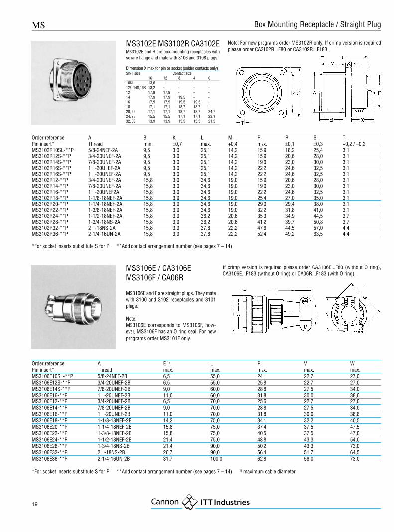
Order reference A B K L M P R S TPin insert* Thread min. ±0,7 max. +0,4 max. ±0,1 ±0,3 +0,2 / –0,2MS3102R10SL-**P 5/8-24NEF-2A 9,5 3,0 25,1 14,2 15,9 18,2 25,4 3,1MS3102R12S-**P 3/4-20UNEF-2A 9,5 3,0 25,1 14,2 15,9 20,6 28,0 3,1MS3102R14S-**P 7/8-20UNEF-2A 9,5 3,0 25,1 14,2 19,0 23,0 30,0 3,1MS3102R16S-**P 1 -20U EF-2A 9,5 3,0 25,1 14,2 22,2 24,6 32,5 3,1MS3102R16S-**P 1 -20UNEF-2A 9,5 3,0 25,1 14,2 22,2 24,6 32,5 3,1MS3102R12-**P 3/4-20UNEF-2A 15,8 3,0 34,6 19,0 15,9 20,6 28,0 3,1MS3102R14-**P 7/8-20UNEF-2A 15,8 3,0 34,6 19,0 19,0 23,0 30,0 3,1MS3102R16-**P 1 -20UNEF2A 15,8 3,0 34,6 19,0 22,2 24,6 32,5 3,1MS3102R18-**P 1-1/8-18NEF-2A 15,8 3,9 34,6 19,0 25,4 27,0 35,0 3,1MS3102R20-**P 1-1/4-18NEF-2A 15,8 3,9 34,6 19,0 29,0 29,4 38.0 3,1MS3102R22-**P 1-3/8-18NEF-2A 15,8 3,9 34,6 19,0 32,2 31,8 41,0 3,1MS3102R24-**P 1-1/2-18NEF-2A 15,8 3,9 36,2 20,6 35,3 34,9 44,5 3,7MS3102R28-**P 1-3/4-18NS-2A 15,8 3,9 36,2 20,6 41,2 39,7 50,8 3,7MS3102R32-**P 2 -18NS-2A 15,8 3,9 37,8 22,2 47,6 44,5 57,0 4,4MS3102R36-**P 2-1/4-16UN-2A 15,8 3,9 37,8 22,2 52,4 49,2 63,5 4,4
*For socket inserts substitute S for P **Add contact arrangement number (see pages 7 – 14)
Order reference A E 1) L P V WPin insert* Thread max. max. max. max. max.MS3106E10SL-**P 5/8-24NEF-2B 6,5 55,0 24,1 22,7 27,0MS3106E12S-**P 3/4-20UNEF-2B 6,5 55,0 25,8 22,7 27,0MS3106E14S-**P 7/8-20UNEF-2B 9,0 60,0 28,8 27,5 34,0MS3106E16-**P 1 -20UNEF-2B 11,0 60,0 31,8 30,0 38,0MS3106E12-**P 3/4-20UNEF-2B 6,5 70,0 25,6 22,7 27,0MS3106E14-**P 7/8-20UNEF-2B 9,0 70,0 28,8 27,5 34,0MS3106E16-**P 1 -20UNEF-2B 11,0 70,0 31,8 30,0 38,8MS3106E18-**P 1-1/8-18NEF-2B 14,2 75,0 34,1 32,2 40,5MS3106E20-**P 1-1/4-18NEF-2B 15,8 75,0 37,4 37,5 47,5MS3106E22-**P 1-3/8-18NEF-2B 15,8 75,0 40,5 37,5 47,0MS3106E24-**P 1-1/2-18NEF-2B 21,4 75,0 43,8 43,3 54,0MS3106E28-**P 1-3/4-18NS-2B 21,4 90,0 50,2 43,3 73,0MS3106E32-**P 2 -18NS-2B 26,7 90,0 56,4 51,7 64,5MS3106E36-**P 2-1/4-16UN-2B 31,7 100,0 62,8 58,0 73,0
*For socket inserts substitute S for P **Add contact arrangement number (see pages 7 – 14) 1) maximum cable diameter
MS3106E / CA3106EMS3106F / CA06R
MS3106E and F are straight plugs. They matewith 3100 and 3102 receptacles and 3101plugs.
Note:MS3106E corresponds to MS3106F, how-ever, MS3106F has an O ring seal. For newprograms order MS3101F only.
If crimp version is required please order CA3106E...F80 (without O ring),CA3106E...F183 (without O ring) or CA06R...F183 (with O ring).
MS3102E MS3102R CA3102EMS3102E and R are box mounting receptacles withsquare flange and mate with 3106 and 3108 plugs.
Dimension X max for pin or socket (solder contacts only)Shell size Contact size
16 12 8 4 010SL 13,6 - - - -12S, 14S,16S 13,2 - - - -12 17,9 17,9 - - -14 17,9 17,9 19,5 - -16 17,9 17,9 19,5 19,5 -18 17,1 17,1 18,7 18,7 -20, 22 17,1 17,1 18,7 18,7 24,724, 28 15,5 15,5 17,1 17,1 23,132, 36 13,9 13,9 15,5 15,5 21,5
Box Mounting Receptacle / Straight Plug
Note: For new programs order MS3102R only. If crimp version is requiredplease order CA3102R...F80 or CA3102R...F183.
20
MS
Dimensions are mmSubject to changes
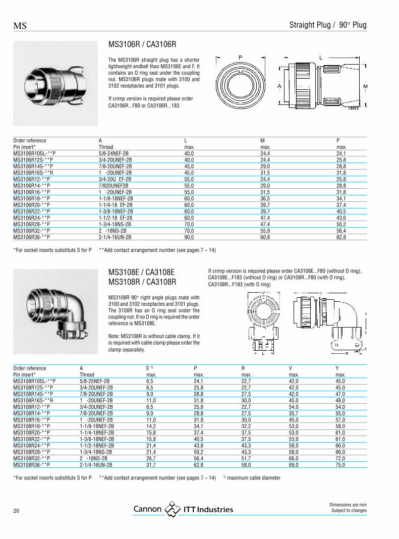
Order reference A E 1) P R V YPin insert* Thread max. max. max. max. max.MS3108R10SL-**P 5/8-25NEF-2B 6,5 24,1 22,7 42,0 45,0MS3108R12S-**P 3/4-20UNEF-2B 6,5 25,8 22,7 42,0 45,0MS3108R14S-**P 7/8-20UNEF-2B 9,0 28,8 27,5 42,0 47,0MS3108R16S-**R 1 -20UNEF-2B 11,0 31,8 30,0 45,0 48,0MS3108R12-**P 3/4-20UNEF-2B 6,5 25,8 22,7 54,0 54,0MS3108R14-**P 7/8-20UNEF-2B 9,0 28,8 27,5 35,7 55,0MS3108R16-**P 1 -20UNEF-2B 11,0 31,8 30,0 45,0 57,0MS3108R18-**P 1-1/8-18NEF-2B 14,2 34,1 32,2 53,0 58,0MS3108R20-**P 1-1/4-18NEF-2B 15,8 37,4 37,5 53,0 61,0MS3108R22-**P 1-3/8-18NEF-2B 15,8 40,5 37,5 53,0 61,0MS3108R24-**P 1-1/2-18NEF-2B 21,4 43,8 43,3 58,0 66,0MS3108R28-**P 1-3/4-18NS-2B 21,4 50,2 43,3 58,0 66,0MS3108R32-**P 2 -18NS-2B 26,7 56,4 51,7 66,0 72,0MS3108R36-**P 2-1/4-16UN-2B 31,7 62,8 58,0 69,0 75,0
*For socket inserts substitute S for P **Add contact arrangement number (see pages 7 – 14) 1) maximum cable diameter
MS3108E / CA3108EMS3108R / CA3108R
MS3108R 90° right angle plugs mate with3100 and 3102 receptacles and 3101 plugs.The 3108R has an O ring seal under thecoupling nut. If no O ring is required the orderreference is MS3108E.
Note: MS3108R is without cable clamp. If itis required with cable clamp please order theclamp separately.
If crimp version is required please order CA3108E...F80 (without O ring),CA3108E...F183 (without O ring) or CA3108R...F80 (with O ring),CA3108R...F183 (with O ring)
Order reference A L M PPin insert* Thread max. max. max.MS3106R10SL-**P 5/8-24NEF-2B 40,0 24,4 24,1MS3106R12S-**P 3/4-20UNEF-2B 40,0 24,4 25,8MS3106R14S-**P 7/8-20UNEF-2B 45,0 29.0 28,8MS3106R16S-**R 1 -20UNEF-2B 45,0 31,5 31,8MS3106R12-**P 3/4-20U EF-2B 55,0 24,4 25,8MS3106R14-**P 7/820UNEF2B 55,0 29,0 28,8MS3106R16-**P 1 -20UNEF-2B 55,0 31,5 31,8MS3106R18-**P 1-1/8-18NEF-2B 60,0 36,5 34,1MS3106R20-**P 1-1/4-18 EF-2B 60,0 39,7 37,4MS3106R22-**P 1-3/8-18NEF-2B 60,0 39,7 40,5MS3106R24-**P 1-1/2-18 EF-28 60,0 47,4 43,6MS3106R28-**P 1-3/4-18NS-2B 70,0 47,4 50,2MS3106R32-**P 2 -18NS-2B 70,0 55,9 56,4MS3106R36-**P 2-1/4-16UN-2B 90,0 60,8 62,8
*For socket inserts substitute S for P **Add contact arrangement number (see pages 7 – 14)
MS3106R / CA3106R
The MS3106R straight plug has a shorterlightweight endbell than MS3106E and F. Itcontains an O ring seal under the couplingnut. MS3106R plugs mate with 3100 and3102 receptacles and 3101 plugs.
If crimp version is required please orderCA3106R...F80 or CA3106R...183
Straight Plug / 90° Plug
MS
21
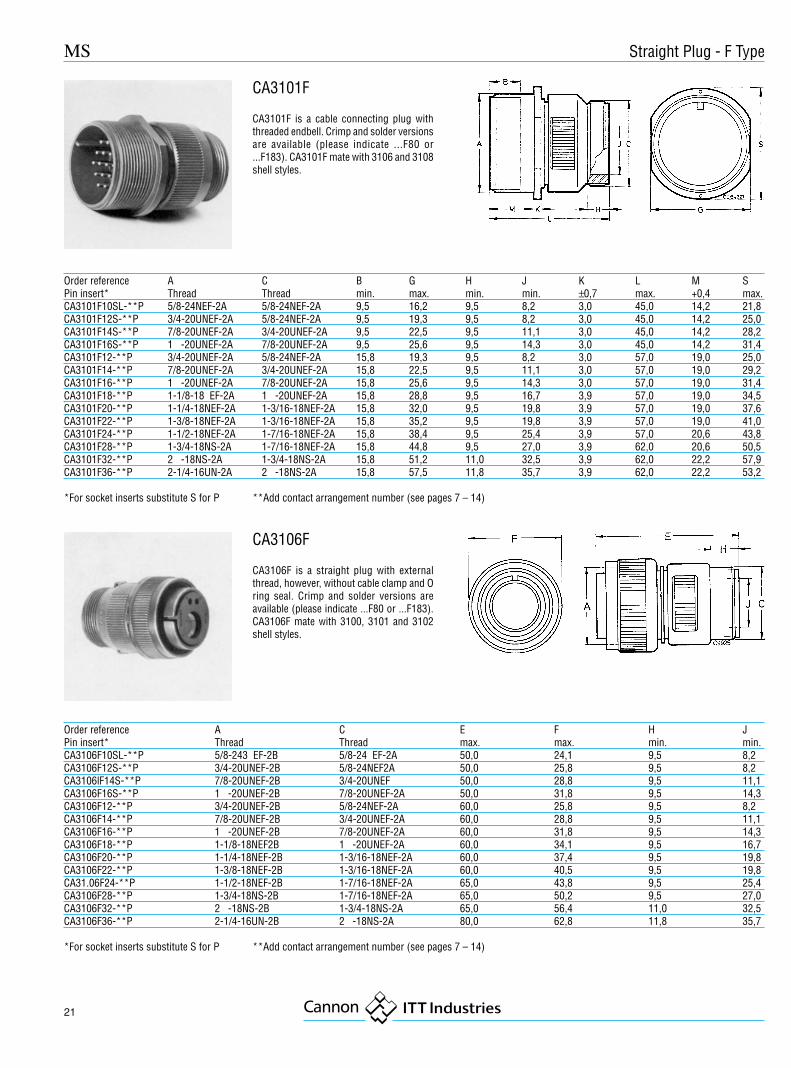
Order reference A C B G H J K L M SPin insert* Thread Thread min. max. min. min. ±0,7 max. +0,4 max.CA3101F10SL-**P 5/8-24NEF-2A 5/8-24NEF-2A 9,5 16,2 9,5 8,2 3,0 45,0 14,2 21,8CA3101F12S-**P 3/4-20UNEF-2A 5/8-24NEF-2A 9,5 19,3 9,5 8,2 3,0 45,0 14,2 25,0CA3101F14S-**P 7/8-20UNEF-2A 3/4-20UNEF-2A 9,5 22,5 9,5 11,1 3,0 45,0 14,2 28,2CA3101F16S-**P 1 -20UNEF-2A 7/8-20UNEF-2A 9,5 25,6 9,5 14,3 3,0 45,0 14,2 31,4CA3101F12-**P 3/4-20UNEF-2A 5/8-24NEF-2A 15,8 19,3 9,5 8,2 3,0 57,0 19,0 25,0CA3101F14-**P 7/8-20UNEF-2A 3/4-20UNEF-2A 15,8 22,5 9,5 11,1 3,0 57,0 19,0 29,2CA3101F16-**P 1 -20UNEF-2A 7/8-20UNEF-2A 15,8 25,6 9,5 14,3 3,0 57,0 19,0 31,4CA3101F18-**P 1-1/8-18 EF-2A 1 -20UNEF-2A 15,8 28,8 9,5 16,7 3,9 57,0 19,0 34,5CA3101F20-**P 1-1/4-18NEF-2A 1-3/16-18NEF-2A 15,8 32,0 9,5 19,8 3,9 57,0 19,0 37,6CA3101F22-**P 1-3/8-18NEF-2A 1-3/16-18NEF-2A 15,8 35,2 9,5 19,8 3,9 57,0 19,0 41,0CA3101F24-**P 1-1/2-18NEF-2A 1-7/16-18NEF-2A 15,8 38,4 9,5 25,4 3,9 57,0 20,6 43,8CA3101F28-**P 1-3/4-18NS-2A 1-7/16-18NEF-2A 15,8 44,8 9,5 27,0 3,9 62,0 20,6 50,5CA3101F32-**P 2 -18NS-2A 1-3/4-18NS-2A 15,8 51,2 11,0 32,5 3,9 62,0 22,2 57,9CA3101F36-**P 2-1/4-16UN-2A 2 -18NS-2A 15,8 57,5 11,8 35,7 3,9 62,0 22,2 53,2
*For socket inserts substitute S for P **Add contact arrangement number (see pages 7 – 14)
CA3101F
CA3101F is a cable connecting plug withthreaded endbell. Crimp and solder versionsare available (please indicate ...F80 or...F183). CA3101F mate with 3106 and 3108shell styles.
Order reference A C E F H JPin insert* Thread Thread max. max. min. min.CA3106F10SL-**P 5/8-243 EF-2B 5/8-24 EF-2A 50,0 24,1 9,5 8,2CA3106F12S-**P 3/4-20UNEF-2B 5/8-24NEF2A 50,0 25,8 9,5 8,2CA3106lF14S-**P 7/8-20UNEF-2B 3/4-20UNEF 50,0 28,8 9,5 11,1CA3106F16S-**P 1 -20UNEF-2B 7/8-20UNEF-2A 50,0 31,8 9,5 14,3CA3106F12-**P 3/4-20UNEF-2B 5/8-24NEF-2A 60,0 25,8 9,5 8,2CA3106F14-**P 7/8-20UNEF-2B 3/4-20UNEF-2A 60,0 28,8 9,5 11,1CA3106F16-**P 1 -20UNEF-2B 7/8-20UNEF-2A 60,0 31,8 9,5 14,3CA3106F18-**P 1-1/8-18NEF2B 1 -20UNEF-2A 60,0 34,1 9,5 16,7CA3106F20-**P 1-1/4-18NEF-2B 1-3/16-18NEF-2A 60,0 37,4 9,5 19,8CA3106F22-**P 1-3/8-18NEF-2B 1-3/16-18NEF-2A 60,0 40,5 9,5 19,8CA31.06F24-**P 1-1/2-18NEF-2B 1-7/16-18NEF-2A 65,0 43,8 9,5 25,4CA3106F28-**P 1-3/4-18NS-2B 1-7/16-18NEF-2A 65,0 50,2 9,5 27,0CA3106F32-**P 2 -18NS-2B 1-3/4-18NS-2A 65,0 56,4 11,0 32,5CA3106F36-**P 2-1/4-16UN-2B 2 -18NS-2A 80,0 62,8 11,8 35,7
*For socket inserts substitute S for P **Add contact arrangement number (see pages 7 – 14)
CA3106F
CA3106F is a straight plug with externalthread, however, without cable clamp and Oring seal. Crimp and solder versions areavailable (please indicate ...F80 or ...F183).CA3106F mate with 3100, 3101 and 3102shell styles.
Straight Plug - F Type

22
MS
Dimensions are mmSubject to changes
Order reference A B L M R S TPin / Socket insert Thread min. max. +0,4 ±0,1 ±0,3 +0,2 / –0,1TBF10SL-**PS 5/8-24NEF-2A 9,5 40,1 14,2 18,2 25,4 3,1TBF12S-**PS 3/4-20UNEF-2A 9,5 40,1 14,2 20,6 28,0 3,1TBF14S-**PS 7/8-20UNEF-2A 9,5 40,1 14,2 23,0 30,0 3,1TBF16S-**PS 1 -20UNEF-2A 9,5 40,1 14,2 24,6 32,5 3,1TBF12-**PS 3/4-20UNEF-2A 15,8 54,4 19,0 20,6 28,0 3,1TBF14-**PS 7/8-20UNEF-2A 15,8 54,4 19,0 23,0 30,0 3,1TBF16-**PS 1 -20UNEF-2A 15,8 54,4 19,0 24,6 32,5 3,1TBF18-**PS 1-1/8-18NEF-2A 15,8 54,5 19,0 27,0 35,0 3,1TBF20-**PS 1-1/4-18NEF-2A 15,8 54,5 19,0 29,4 38,0 3,1TBF22-**PS 1-3/8-18NEF-2A 15,8 54,5 19,0 31,8 41,0 3,1TBF24-**PS 1-1/2-18NEF-2A 15,8 54,5 20,5 34,9 44,5 3,7TBF28-**PS 1-3/4-18NS-2A 15,8 54,5 20,6 39,7 50,8 3,7TBF32-**PS 2 -18NS-2A 15,8 54,5 22,2 44,5 57,0 4,4TBF36-**PS 2-1/4-16UN-2A 15,8 54,5 22,2 49,2 63,5 4,4
*For socket inserts substitute S for P **Add contact arrangement number (see pages 7 – 14)
TBF
TBF is a through-bulkhead which mates with3106 and 3108 plugs.
Order reference A B C D E F L PPin insert* Thread min. max. ±0,2 ±0,2 ±0,5 max. max.CA3106E10SL--**-P-DN 5/8-24NEF-2B 7,7 13,2 15,5 17,0 11,7 11,7 50,0CA3105E12S-**-P-DN 3/4-20UNEF-2B 7,9 13,2 15,5 17,8 11.8 5ß.ß 25,6CA3106E14S-**-P-DN 7/8-20UNEF-2B 10,6 17,0 19,1 19,1 11,7 50,0 28,6CA3106E16S-**-P-DN 1 -20UNEF-2B 13,5 21,9 23,9 23,9 11,5 50,0 31,8CA3106E12-**-P-DN 3/4-20UNEF-2B 7,9 13,2 15,5 17,8 11,7 50,0 25,6CA3106E14-**-P-DN 7/8-20UNEF-2B 10,6 17,0 19,1 20,1 11,7 60,0 28,6CA3106E16-**-P-DN 1 -20UNEF-2B 13,5 21,9 23,9 23,5 11,5 60,0 31,8CA3106E18-**-P-DN 1-1/8-18NEF-2B 14,6 21,9 23,9 26,5 12,7 60,0 34,1CA3106E20-**-P-DN 1-1/4-18NEF-2B 18,5 26,6 29,6 30,2 12,7 65,0 37,3CA3106E22-**-P-DN 1-3/8-18NEF-2B 20,8 26,2 29,6 33,6 12,7 65,0 40,5CA3106E24-**-P-DN 1-1/2-16NEF-2B 24,6 34,5 37,8 36,1 12,7 65,0 43,8CA3106E28-**-P-DN 1-3/4-18NS-2B 27,0 34,5 37,8 41,4 12,7 65,0 50,0CA3106E32-**-P-DN 2 -18NS-2B 33,3 43,6 47,8 48,6 15,2 70,0 56,3CA3106E36-**-P-DN 2-1/4-16UN-2B 38,5 43,6 47,8 54,8 15,2 80,0 62,7
*For socket inserts substitute S for P **Add contact arrangement number (see pages 7 – 14)
CA3106E-DN
CA3106E-DN is a straight plug with endbellfor shrink boot adapters. Crimp and solderversions are available (please indicate ...F80or ...F183). CA3106-DN mate with 3100,3101 and 3102 shell styles.
Straight Plug with Shrink Boot Adapter / Through-Bulkhead
MS
23
Order reference Shell size C L R Smax. max. –0,3 –0,3
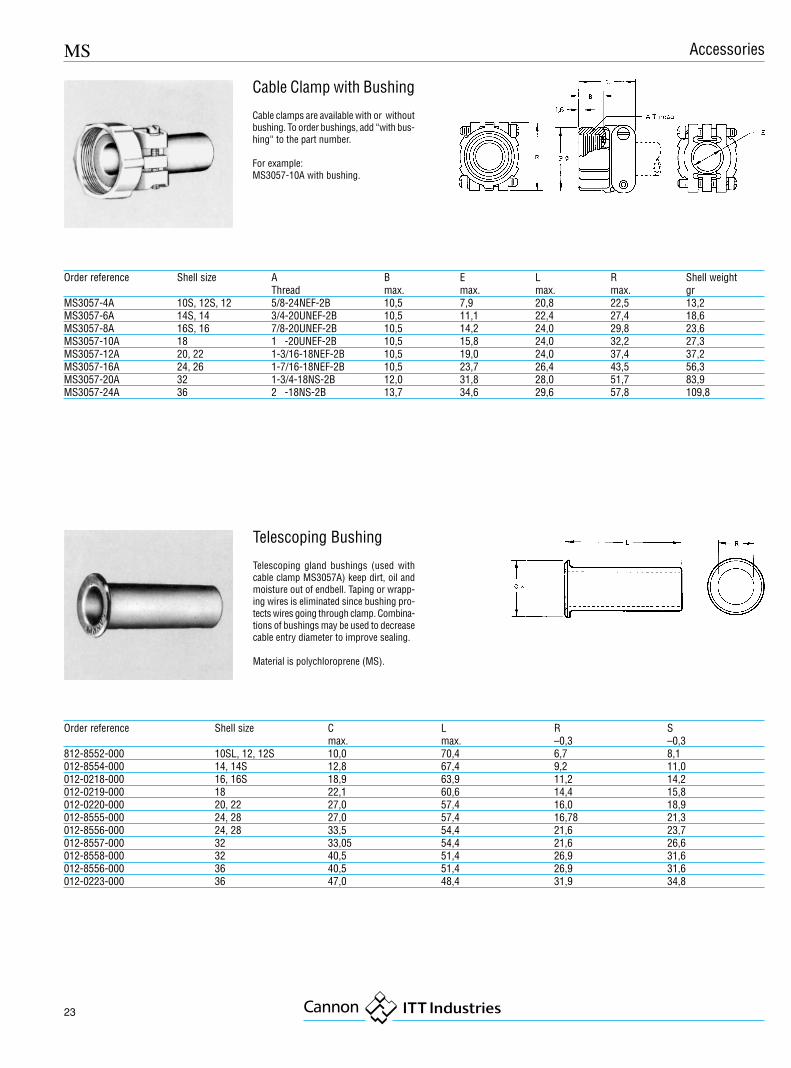
812-8552-000 10SL, 12, 12S 10,0 70,4 6,7 8,1012-8554-000 14, 14S 12,8 67,4 9,2 11,0012-0218-000 16, 16S 18,9 63,9 11,2 14,2012-0219-000 18 22,1 60,6 14,4 15,8012-0220-000 20, 22 27,0 57,4 16,0 18,9012-8555-000 24, 28 27,0 57,4 16,78 21,3012-8556-000 24, 28 33,5 54,4 21,6 23,7012-8557-000 32 33,05 54,4 21,6 26,6012-8558-000 32 40,5 51,4 26,9 31,6012-8556-000 36 40,5 51,4 26,9 31,6012-0223-000 36 47,0 48,4 31,9 34,8
Telescoping Bushing
Telescoping gland bushings (used withcable clamp MS3057A) keep dirt, oil andmoisture out of endbell. Taping or wrapp-ing wires is eliminated since bushing pro-tects wires going through clamp. Combina-tions of bushings may be used to decreasecable entry diameter to improve sealing.
Material is polychloroprene (MS).
Order reference Shell size A B E L R Shell weightThread max. max. max. max. gr
MS3057-4A 10S, 12S, 12 5/8-24NEF-2B 10,5 7,9 20,8 22,5 13,2MS3057-6A 14S, 14 3/4-20UNEF-2B 10,5 11,1 22,4 27,4 18,6MS3057-8A 16S, 16 7/8-20UNEF-2B 10,5 14,2 24,0 29,8 23,6MS3057-10A 18 1 -20UNEF-2B 10,5 15,8 24,0 32,2 27,3MS3057-12A 20, 22 1-3/16-18NEF-2B 10,5 19,0 24,0 37,4 37,2MS3057-16A 24, 26 1-7/16-18NEF-2B 10,5 23,7 26,4 43,5 56,3MS3057-20A 32 1-3/4-18NS-2B 12,0 31,8 28,0 51,7 83,9MS3057-24A 36 2 -18NS-2B 13,7 34,6 29,6 57,8 109,8
Cable Clamp with Bushing
Cable clamps are available with or withoutbushing. To order bushings, add “with bus-hing“ to the part number.
For example:MS3057-10A with bushing.
Accessories

24
MS
Dimensions are mmSubject to changes
Plastic protective caps
Material: PolyethyleneColour: Red
Order reference MS3100 / 3101 / 3102 MS3106 / 3108 A B C Dmax. max. ±0,2 max.
025-0460-000 10SL 21,5 17,8 15,2 16,9025-0477-000 10 SL 20,4 12,5 14,0 15,7025-0478-000 12S, 12 23,1 14,6 16,8 18,5025-0462-000 12S, 12 24,7 17,8 18,5 20,2025-0479-000 14S, 14 26,3 14,6 19,9 21,6025-0463-000 14S, 14 27,8 17,8 21,6 23,3025-0480-000 16S, 16 29,5 14,6 23,1 24,8025-0498-000 16S, 16 31,5 17,8 25,1 26,8025-0484-000 18 32,8 14,6 25,9 27,8025-0507-000 18 34,7 17,8 28,2 30,1025-0467-000 20 35,4 17,8 28,3 30,2025-0468-000 20 38,1 17,8 31,8 33,4025-0469-000 22 39,1 14,6 32,6 34,2025-0486-000 22 41,4 17,8 34,5 36,5025-0487-000 24 42,3 14,6 35,5 37,4025-0510-000 24 44,2 17,8 37,8 39,8025-0488-000 28 48,4 14,6 41,6 43,5025-0501-000 28 50,4 17,8 43,9 45,9025-0489-000 32 54,8 14,6 48,0 49,9025-0502-000 32 57,0 17,8 50,3 52,2025-0490-000 36 61,3 14,6 54,2 56,3025-0503-000 36 63,4 17,8 56,6 58,6
Dust caps for mating side of plugs only.
Accessories
Wire hole fillers
Where contacts are not used, the contact cavities are to be closed with wire hole filers
Contact size Wire size Part number ColourAWG metric AWG- 10 20 225-1000-000 red16S/16 15S/15 16 225-0017-000 blue12 25 12 225-0018-000 yellow8 60/100 8 225-0019-000 white4 160 4 225-8502-000 green0 500 0 225-8503-000 black
MS
25
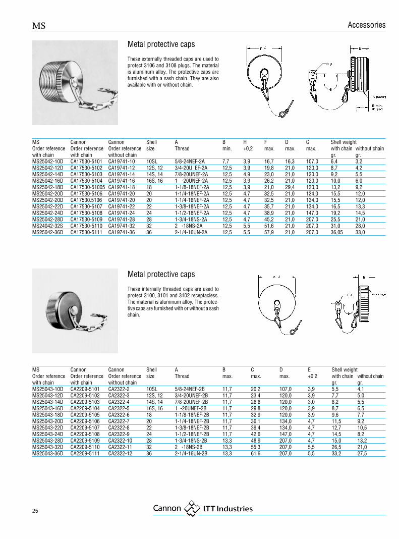
MS Cannon Cannon Shell A B C D E Shell weightOrder reference Order reference Order reference size Thread max. max. max. +0,2 with chain without chainwith chain with chain without chain gr. gr.MS25043-10D CA2209-5101 CA2322-2 10SL 5/8-24NEF-2B 11,7 20,2 107,0 3,9 5,5 4,1MS25043-12D CA2209-5102 CA2322-3 12S, 12 3/4-20UNEF-2B 11,7 23,4 120,0 3,9 7,7 5,0MS25043-14D CA2209-5103 CA2322-4 14S, 14 7/8-20UNEF-2B 11,7 26,6 120,0 3,0 8,2 5,5MS25043-16D CA2209-5104 CA2322-5 16S, 16 1 -20UNEF-2B 11,7 29,8 120,0 3,9 8,7 6,5MS25043-18D CA2209-5105 CA2322-6 18 1-1/8-18NEF-2B 11,7 32,9 120,0 3,9 9,6 7,7MS25043-20D CA2209-5106 CA2322-7 20 1-1/4-18NEF-2B 11,7 36,1 134,0 4,7 11,5 9,2MS25043-22D CA2209-5107 CA2322-8 22 1-3/8-18NEF-2B 11,7 39,4 134,0 4,7 12,7 10,5MS25043-24D CA2209-5108 CA2322-9 24 1-1/2-18NEF-2B 11,7 42,6 147,0 4,7 14,5 8,2MS25043-28D CA2209-5109 CA2322-10 28 1-3/4-18NS-2B 13,3 48,9 207,0 4,7 15,0 13,2MS25043-32D CA2209-5110 CA2322-11 32 2 -18NS-2B 13,3 55,3 207,0 5,5 26,5 21,0MS25043-36D CA2209-5111 CA2322-12 36 2-1/4-16UN-2B 13,3 61,6 207,0 5,5 33,2 27,5
Metal protective caps
These externally threaded caps are used toprotect 3106 and 3108 plugs. The materialis aluminum alloy. The protective caps arefurnished with a sash chain. They are alsoavailable with or without chain.
MS Cannon Cannon Shell A B H F D G Shell weightOrder reference Order reference Order reference size Thread min. +0,2 max. max. max. with chain without chainwith chain with chain without chain gr. gr.MS25042-10D CA17530-5101 CA19741-10 10SL 5/8-24NEF-2A 7,7 3,9 16,7 16,3 107,0 6,4 3,2MS25042-12D CA17530-5102 CA19741-12 12S, 12 3/4-20U EF-2A 12,5 3,9 19,8 21,0 120,0 8,7 4,2MS25042-14D CA17530-5103 CA19741-14 14S, 14 7/8-20UNEF-2A 12,5 4,9 23,0 21,0 120,0 9,2 5,5MS25042-16D CA17530-5104 CA19741-16 16S, 16 1 -20UNEF-2A 12,5 3,9 26,2 21,0 120,0 10,0 6,0MS25042-18D CA17530-51005 CA19741-18 18 1-1/8-18NEF-2A 12,5 3,9 21,0 29,4 120,0 13,2 9,2MS25042-20D CA17530-5106 CA19741-20 20 1-1/4-18NEF-2A 12,5 4,7 32,5 21,0 124,0 15,5 12,0MS25042-20D CA17530.5106 CA19741-20 20 1-1/4-18NEF-2A 12,5 4,7 32,5 21,0 134,0 15,5 12,0MS25042-22D CA17530-5107 CA19741-22 22 1-3/8-18NEF-2A 12,5 4,7 35,7 21,0 134,0 16,5 13,3MS25042-24D CA17530-5108 CA19741-24 24 1-1/2-18NEF-2A 12,5 4,7 38,9 21,0 147,0 19,2 14,5MS25042-28D CA17530-5109 CA19741-28 28 1-3/4-18NS-2A 12,5 4,7 45,2 21,0 207.0 25,5 21,0MS24042-32S CA17530-5110 CA19741-32 32 2 -18NS-2A 12,5 5,5 51,6 21,0 207,0 31,0 28,0MS25042-36D CA17530-5111 CA19741-36 36 2-1/4-16UN-2A 12,5 5,5 57,9 21,0 207,0 36,05 33,0
Metal protective caps
These internally threaded caps are used toprotect 3100, 3101 and 3102 receptacless.The material is aluminum alloy. The protec-tive caps are furnished with or without a sashchain.
Accessories
26
MS
Dimensions are mmSubject to changes
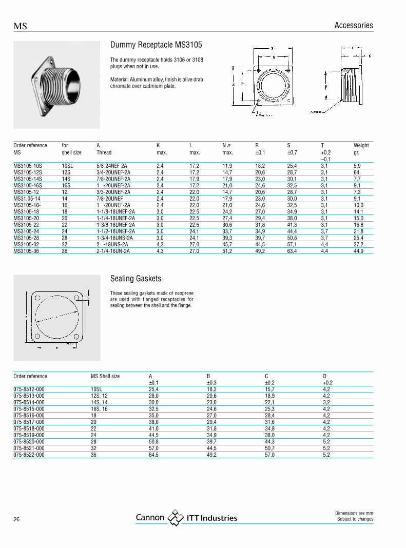
Order reference MS Shell size A B C D±0,1 ±0,3 ±0,2 +0,2
075-8512-000 10SL 25,4 18,2 15,7 4,2075-8513-000 12S, 12 28,0 20,6 18,9 4,2075-8514-000 14S, 14 30,0 23,0 22,1 3,2075-8515-000 16S, 16 32,5 24,6 25,3 4,2075-8516-000 18 35,0 27,0 28,4 4,2075-8517-000 20 38,0 29,4 31,6 4,2075-8518-000 22 41,0 31,8 34,8 4,2075-8519-000 24 44,5 34,9 38,0 4,2075-8520-000 28 50,8 39,7 44,3 5,2075-8521-000 32 57,0 44,5 50,7 5,2075-8522-000 36 64,5 49,2 57,0 5,2
Order reference for A K L N Æ R S T WeightMS shell size Thread max. max. max. ±0,1 ±0,7 +0,2 gr.
–0,1MS3105-10S 10SL 5/8-24NEF-2A 2,4 17,2 11,9 18,2 25,4 3,1 5,9MS3105-12S 12S 3/4-20UNEF-2A 2,4 17,2 14,7 20,6 28,7 3,1 64,MS3105-14S 14S 7/8-20UNEF-2A 2,4 17,9 17,9 23,0 30,1 3,1 7,7MS3105-16S 16S 1 -20UNEF-2A 2,4 17,2 21,0 24,6 32,5 3,1 9,1MS3105-12 12 3/3-20UNEF-2A 2,4 22,0 14,7 20,6 28,7 3,1 7,3MS31,05-14 14 7/8-20UNEF 2,4 22,0 17,9 23,0 30,0 3,1 9,1MS3105-16- 16 1 -20UNEF-2A 2,4 22,0 21,0 24,6 32,5 3,1 10,0MS3105-18 18 1-1/8-18UNEF-2A 3,0 22,5 24,2 27,0 34,9 3,1 14,1MS3105-20 20 1-1/4-18UNEF-2A 3,0 22,5 27,4 29,4 38,0 3,1 15,0MS3105-22 22 1-3/8-18UNEF-2A 3,0 22,5 30,6 31,8 41,3 3,1 16,8MS3105-24 24 1-1/2-18UNEF-2A 3,0 24,1 33,7 34,9 44,4 3,7 21,8MS3105-28 28 1-3/4-18UNS-2A 3,0 24,1 39,3 39,7 50,8 3,7 25,4MS3105-32 32 2 -18UNS-2A 4,3 27,0 45,7 44,5 57,1 4,4 37,2MS3105-36 36 2-1/4-16UN-2A 4,3 27,0 51,2 49,2 63,4 4,4 44,9
Dummy Receptacle MS3105
The dummy receptacle holds 3106 or 3108plugs when not in use.
Material: Aluminum alloy, finish is olive drabchromate over cadmium plate.
Accessories
Sealing Gaskets
These sealing gaskets made of neopreneare used with flanged receptacles forsealing between the shell and the flange.

MS
27
Contact Termination size Cannon Part number d1 d4 d6 d7 l1 l3size mm2 AWG with finish +0,05 ± 0,15 ± 0,5
A36 A17610/20 0,50 - 1,0 20/18 030-8585-006 030-8585-006 1,04 1,5-0,05 1,5+0,05 2,4-0,05 28,4 4,75
0,2 - 0,4 24/22 030-8585-010 - 1,04 1,5-0,05 1,5+0,05 2,4-0,05 28,4 4,7515S/16S 0,75 - 1,5 18 / 16 030-8586-000 030-8586-006 1,6 1,75-0,1 1,75+0,08 2,75-0,05 27,4 3,85
0,3 - 0,6 22 / 20 030-8744-000 030-8744-006 1,6 1,75-0,1 1,2+0,1 2,75-0,05 27,4 3,850,14 - 0,38 22 / 26 030-8586-010 - 1,6 1,75-0,1 0,9+0,05 2,75-0,05 27,4 3,85
15/16 0,75 - 1,5 18 / 16 030-8587-000 030-8587-006 1,6 1,75-0,1 1,75+0,08 2,75-0,05 31,4 7,90,3 - 0,6 22 / 20 030-8659-000 030-8659-006 1,6 1,75-0,1 1,2+0,1 2,75-0,05 31,4 7,90,14 - 0,38 22 / 26 030-8587-030 030-8687-036 1,6 1,75-0,1 0,9+0,05 2,75-0,05 31,4 7,9
25/12 2,0 - 3,0 14 / 12 030-8588-000 030-8588-006 2,4 3,3-0,15 2,5+0,1 3,8-0,1 37,0 7,90,75 - 1, 5 18 / 16 030-8588-010 030-8588-016 2,4 3,3-0,15 1,75+0,08 3,8-0,1 37,0 7,94,0 - 030-8588-054 - 2,4 3,3-0,15 2,8+0,1 3,8-0,1 37,0 7,9
330-8588-000 030-8588-006 2,4 3,3-0,15 2,5+0,1 3,8-0,1 37,0 7,9100/60/8 - 8 030-8612-000 030-8612-006 3,6 6,25-0,15 4,55+0,1 6,8-0,1 39,6 6,35
6,0 10 030-8589-000 030-8589-006 3,6 6,25-0,15 3,5+0,1 6,8-0,1 39,6 6,3510,0 - 030-8590-000 030-8590-006 3,6 6,25-0,15 4,8+0,1 6,8-0,1 39,6 6,352,0 - 3,0 14 / 12 030-8612-010 - 3,6 6,25-0,15 2,5+0,05 6,8-0,1 39,6 6,354,0 - 030-8612-020 - 3,6 6,25-0,15 2,8+0,1 6,8-0,1 39,6 6,35
160/4 - 4 030-8613-000 030-8613-006 5,75 9,55-0,15 7,10+0,15 9,55-0,1 39,6 6,3516,00 - 030-8591-000 030-8591-006 5,75 9,55-0,15 6,20+0,15 9,55-0,1 39,6 6,3510,00 - 030-8591-020 - 5,75 9,55-0,15 4,80+0,15 9,55-0,1 39,6 6,35- 6 030-8613-010 - 5,75 9,55-0,15 5,70+0,15 9,55-0,1 39,6 6,35
500/0 - 0 030-8614-000 030-8614-006 9,10 13,55-0,15 11,5+0,15 14,35-0,1 41,0 6,3550,00 - 030-8592-000 030-8592-006 9,10 13,55-0,15 10,7+0,15 14,35-0,1 41,0 6,3525,00 4 030-8614-010 - 9,10 13,55-0,15 7,6+0,15 14,35-0,1 41,0 6,3535,00 2 030-8614-020 - 9,10 13,55-0,15 9,1+0,15 14,35-0,1 41,0 6,3516,00 - 030-8614-030 - 9,10 13,55-0,15 6,2+0,15 14,35-0,1 41,0 6,35
Pin Contacts
Dimensions are mm
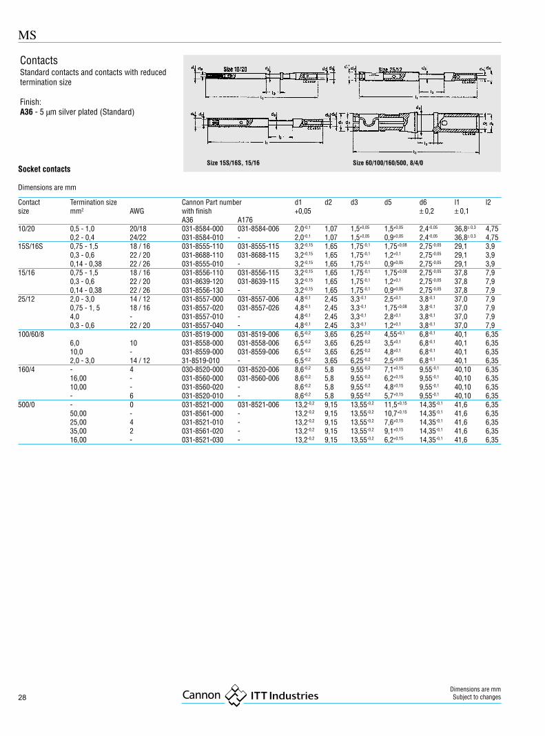
ContactsStandard contacts and contacts with reducedtermination size
Finish:A36 - 5 µm silver plated (Standard)
Size 15S/16S, 15/16, 25/12, 60/100/8, 160/4, 500/0 Size 10/20
28
MS
Dimensions are mmSubject to changes
Contact Termination size Cannon Part number d1 d2 d3 d5 d6 l1 l2size mm2 AWG with finish +0,05 ± 0,2 ± 0,1
A36 A17610/20 0,5 - 1,0 20/18 031-8584-000 031-8584-006 2,0-0,1 1,07 1,5+0,05 1,5+0,05 2,4-0,05 36,8± 0,3 4,75
0,2 - 0,4 24/22 031-8584-010 - 2,0-0,1 1,07 1,5+0,05 0,9+0,05 2,4-0,05 36,8± 0,3 4,7515S/16S 0,75 - 1,5 18 / 16 031-8555-110 031-8555-115 3,2-0,15 1,65 1,75-0,1 1,75+0,08 2,75-0,05 29,1 3,9
0,3 - 0,6 22 / 20 031-8688-110 031-8688-115 3,2-0,15 1,65 1,75-0,1 1,2+0,1 2,75-0,05 29,1 3,90,14 - 0,38 22 / 26 031-8555-010 - 3,2-0,15 1,65 1,75-0,1 0,9+0,05 2,75-0,05 29,1 3,9
15/16 0,75 - 1,5 18 / 16 031-8556-110 031-8556-115 3,2-0,15 1,65 1,75-0,1 1,75+0,08 2,75-0,05 37,8 7,90,3 - 0,6 22 / 20 031-8639-120 031-8639-115 3,2-0,15 1,65 1,75-0,1 1,2+0,1 2,75-0,05 37,8 7,90,14 - 0,38 22 / 26 031-8556-130 - 3,2-0,15 1,65 1,75-0,1 0,9+0,05 2,75-0,05 37,8 7,9
25/12 2,0 - 3,0 14 / 12 031-8557-000 031-8557-006 4,8-0,1 2,45 3,3-0,1 2,5+0,1 3,8-0,1 37,0 7,90,75 - 1, 5 18 / 16 031-8557-020 031-8557-026 4,8-0,1 2,45 3,3-0,1 1,75+0,08 3,8-0,1 37,0 7,94,0 - 031-8557-010 - 4,8-0,1 2,45 3,3-0,1 2,8+0,1 3,8-0,1 37,0 7,90,3 - 0,6 22 / 20 031-8557-040 - 4,8-0,1 2,45 3,3-0,1 1,2+0,1 3,8-0,1 37,0 7,9
100/60/8 031-8519-000 031-8519-006 6,5-0,2 3,65 6,25-0,2 4,55+0,1 6,8-0,1 40,1 6,356,0 10 031-8558-000 031-8558-006 6,5-0,2 3,65 6,25-0,2 3,5+0,1 6,8-0,1 40,1 6,3510,0 - 031-8559-000 031-8559-006 6,5-0,2 3,65 6,25-0,2 4,8+0,1 6,8-0,1 40,1 6,352,0 - 3,0 14 / 12 31-8519-010 - 6,5-0,2 3,65 6,25-0,2 2,5+0,05 6,8-0,1 40,1 6,35
160/4 - 4 030-8520-000 031-8520-006 8,6-0,2 5,8 9,55-0,2 7,1+0,15 9,55-0,1 40,10 6,3516,00 - 031-8560-000 031-8560-006 8,6-0,2 5,8 9,55-0,2 6,2+0,15 9,55-0,1 40,10 6,3510,00 - 031-8560-020 - 8,6-0,2 5,8 9,55-0,2 4,8+0,15 9,55-0,1 40,10 6,35- 6 031-8520-010 - 8,6-0,2 5,8 9,55-0,2 5,7+0,15 9,55-0,1 40,10 6,35
500/0 - 0 031-8521-000 031-8521-006 13,2-0,2 9,15 13,55-0,2 11,5+0,15 14,35-0,1 41,6 6,3550,00 - 031-8561-000 - 13,2-0,2 9,15 13,55-0,2 10,7+0,15 14,35-0,1 41,6 6,3525,00 4 031-8521-010 - 13,2-0,2 9,15 13,55-0,2 7,6+0,15 14,35-0,1 41,6 6,3535,00 2 031-8561-020 - 13,2-0,2 9,15 13,55-0,2 9,1+0,15 14,35-0,1 41,6 6,3516,00 - 031-8521-030 - 13,2-0,2 9,15 13,55-0,2 6,2+0,15 14,35-0,1 41,6 6,35
ContactsStandard contacts and contacts with reducedtermination size
Finish:A36 - 5 µm silver plated (Standard)
Socket contacts
Dimensions are mm
Size 15S/16S, 15/16 Size 60/100/160/500, 8/4/0

MS
29
Extraction tools
for contact extraction from insulator
Part No. Order reference Contact sizeCET-F80-16 121 086-0081 15S/15/10CET-F80-12 121 086-0080 25CET-8 121086-0079 8/100CET-4 121086-0078 4/160CET-0 121086-0077 0/500
for pin contacts acc to VG95234 and Cannon contacts with reduced termination size
Contact Wire size Hand crimp tools Pneumatic crimp toolssize mm2 AWG Type Crimp locator Standard model Crimp locator Universal model Crimp locator
10/20 10 – 2 8 – 14 600 098 600 325
15S/16S 0,2 – 1,0 16 – 22 M22520-1-01 600 082(Order reference TH 452 612 871* 612 141* TH 452
15/16 0,2 – 1,0 16 – 22 995-0001-585) 604 092
25/12 0,2 – 1,0 12 – 18 600 099
Hydraulic basic tool: Hydraulic pumps: Crimp locators100/60/8 10 – 2 8 – 14 - Crimp head 463200000.601 - Hand pump 4601.00000.330 317-8531-000
- High pressure hose, 2 m, 4604.0000.020 - Foot pedal 4601.510000.330 317-8531-001160/4 10 – 16 4 – 6 - Electric pump, foot operated, 4609.00000.020 317-8532-000
317-8532-001500/0 14 – 50 0 – 4 317-8533-000
317-8533-001* bench mount with foot pedal 611 380
Tooling
for socket contacts acc to VG95234 and Cannon contacts with reduced termination size
Contact Wire size Hand crimp tools Pneumatic crimp toolssize mm2 AWG Type Crimp locator Standard model Crimp locator Universal model Crimp locator
10/20 0,2 – 1,0 18 – 24 600 098 600 325
15S/16S 0,2 – 1,0 16 – 22 M22520-1-01 600 083(Order reference TH 452 612 871* 612 141* TH 452
15/16 0,2 – 1,0 16 – 22 995-0001-585) 600 081
25/12 0,2 – 1,0 12 – 18 600 099
Hydraulic basic tool: Hydraulic pumps: Crimp locators100/60/8 2 – 10 8 – 14 - Crimp head 463200000.601 - Hand pump 4601.00000.330 317-8531-000
- High pressure hose, 2 m, 4604.0000.020 - Foot pedal 4601.510000.330 317-8531-001160/4 10 – 16 4 – 6 - Electric pump, foot operated, 4609.00000.020 317-8532-000
317-8532-001500/0 14 – 50 0 – 4 317-8533-000
317-8533-001* bench mount with foot pedal 611 380
Insertion tools
for contact insertion into insulator
Part No. Order reference Contact sizeCIT-F80-16 or 121 086-0097 orCIT-16 121 086-3008 15S/15CIT-F80-12 or 121 086-0096 orCIT-12 121 086-3007 25CIT-F80-20 121086-0098 10CIT-8 121086-0095 8/100CIT-4 121086-0094 4/160CIT-0 121086-0093 0/500
Crimp contacts
Connectors of series MS-E and MS-R are alsoavailable with crimp contacts for metric wiresizes. In order to wire, insert and extract thesecontacts the tools mentioned on this page areneeded. All tools have to be ordered separately.
Ask for our detailed Wiring and AssemblyInstruction.

30
MS
Dimensions are mmSubject to changes
Product Safety InformationTHIS NOTE SHOULD BE READ IN CONJUNCTIONWITH THE PRODUCT DATA SHEET/CATALOGUE.FAILURE TO OBSERVE THE ADVICE IN THIS INFOR-MATION SHEET AND THE OPERATING CONDITIONSSPECIFIED IN THE PRODUCT DATA SHEET/CATALOGUE COULD RESULT IN HAZARDOUSSITUATIONS.
1. MATERIAL CONTENT AND PHYSICALFORMElectrical connectors do not usually containhazardous materials. They contain conducting andnon-conducting materials and can be divided intotwo groups.
a) Printed circuit types and low cost audio typeswhich employ all plastic insulators and casings.
b) Rugged, Fire Barrier and High Reliability typeswith metal casings and either natural rubber,synthetic rubber, plastic or glass insulatingmaterials.
Contact materials vary with type of connector andalso application and are usually manufactured fromeither copper, copper alloys, nickel, alumel, chromelor steel. In special applications, other alloys maybe specified.
2. FIRE CHARACTERISTICS AND ELECTRICSHOCK HAZARDThere is no fire hazard when the connector iscorrectly wired and used within the specifiedparameters. Incorrect wiring or assembly of theconnector or careless use of metal tools orconductive fluids, or transit damage to any of thecomponent parts may cause electric shock orburns. Live circuits must not be broken by sepa-rating mated connectors as this may cause arcing,ionisation and burning.Heat dissipation is greater at maximum resistancein a circuit. Hot spots may occur when resistanceis raised locally by damage, e.g. cracked ordeformed contacts, broken strands of wire. Localoverheating may also result from the use of theincorrect application tools or from poor qualitysoldering or slack screw terminals. Overheating mayoccur if the ratings in the Product Data Sheet/Catalogue are exceeded and can cause breakdownof insulation and hence electric shock.If heating is allowed to continue it intensifies byfurther increasing the local resistance through lossof temper of spring contacts, formation of oxidefilm on contacts and wires, and leakage currentsthrough carbonisation of insulation and trackingpaths. Fire can then result in the presence ofcombustible materials and this may release noxiousfumes. Overheating may not be visually apparent.Burns may result from touching overheatedcomponents.
ITT Industries, Cannon manufactures the highest quality products available in the marketplace; however these productsare intended to be used in accordance with the specifications in this catalog. Any use or application that deviates fromstated operating specifications is not recommended and may be unsafe. No information and data contained in this catalogshall be construed to create any liability on the part of Cannon. Any new issue of this catalog shall automatically invalidateand supersede any and all previous issues. A limited warranty applies to Cannon products. Except for obligationsassumed by Cannon under this warranty, Cannon shall not be liable for any loss, damage, cost of repairs, incidentalor consequential damages of any kind, whether or not based on express or implied warranty, contract, negligence orstrict liability arising in connection with the design, manufacture, sale, use or repair of the products. Product availability,prices and delivery dates are exclusively subject to our respective order confirmation form; the same applies to ordersbased on development samples delivered. This catalog is not to be construed as an offer. It is intended merely as aninvitation to make an offer. By this publication, Cannon does not assume responsibility or any liability for any patentinfringements or other rights of third parties which may result from its use. Reprinting this catalog is generally permitted,indicating the source. However, Cannon's prior consent must be obtained in all cases.
Cannon is a trademark of ITT Industries, Inc
3. HANDLINGCare must be taken to avoid damage to anycomponent parts of electrical connectors duringinstallation and use. Although there are normallyno sharp edges, care must be taken when handlingcertain components to avoid injury to fingers.Electrical connectors may be damaged in transit tothe customers, and damage may result in creationof hazards. Products should therefore be examinedprior to installation/use and rejected if found to bedamaged.
4. DISPOSALIncineration of certain materials may releasenoxious or even toxic fumes.
5. APPLICATIONConnectors with exposed contacts should not beselected for use on the current supply side of anelectrical circuit, because an electric shock couldresult from touching exposed contacts on anunmated connector. Voltages in excess of 30 V acor 42.5 V dc are potentially hazardous and careshould be taken to ensure that such voltages cannot be transmitted in any way to exposed metal partsof the connector body. The connector and wiringshould be checked, before making live, to have nodamage to metal parts or insulators, no solder blobs,loose strands, conducting lubricants, swarf, or anyother undesired conducting particles. Insulationresistance should be checked to make certain thatno low resistance joints or spurious conducting pathare existing between contacts and exposed metalparts of the connector body. Further the contactresistance of the connectors should be measuredwithin the electrical circuit in order to identify highresistances which result in excessive connectorheating.
Always use the correct application tools as specifiedin the Data Sheet/Catalogue.
Do not permit untrained personnel to wire, assembleor tramper with connectors.
For operation voltage please see appropriate nationalregulations.
IMPORTANT GENERAL INFORMATION.
1. Air and creepage paths/Operating voltageThe admissible operating voltages depend on theindividual applications and the valid national andother applicable safety regulations.
For this reason the air and creepage path dataare only reference values. Observe reduction of airand creepage paths due to PC board and/or harness-ing.
2. TemperatureAll information given are temperature limits. Theoperation temperature depends on the individualapplication.
3. Other important informationCannon continuously endeavours to improve theirproducts. Therefore, Cannon products may deviatefrom the description, technical data and shape asshown in this catalogue and data sheets.
4. Harnessing and Assembly InstructionsIf applicable, our special harnessing and/or assem-bly instruction has to be adhered to. This is provid-ed at request.
Cannon Worldwide Facilities
AustriaAfrikanergasse 31020 ViennaFAX: (1) 2160948 PH: (1) 2160947BeneluxRue Col. Bourg Str. 105A1140 Brussels, BelgiumFAX: (02) 7269201 PH: (02) 726 75 94NLFAX: 31.35.691.8796 PH: 31.35.691.6855ChinaNo. 24, 2 BlockTaohuawu New DistrictZhenjiang, JiangsuP.R.C.FAX: 86 511 4428616 PH: 86 511 443 3399DenmarkPark Allé 287 A2605 BrøndbyFAX: 43 43 58 58 PH: 43 45 52 88FinlandVirkatie 11510 VantaaFAX:+358 9 70039188 PH: +358 9 70039180France2, Ave Sablons Bouillants, B.P. 13377109 MeauxFAX: (1) 64 33 16 82 PH: (1) 60 24 51 51GermanyPostfach 11 20, 71365 WeinstadtCannonstrasse 1, 71384 WeinstadtFAX: (07151) 699217 P H: (07151) 699-0Hong Kong906 New World Office BuildingWest Wing, 20 Salisbury RoadTsim Sha Tsui, KowloonFAX: (852) 2369-5651 PH: (852) 2732-2720
ItalyVia Panzeri 1020123 MilanoFAX: (02) 8372036 PH: (02) 581801Japan5362-1, 5-chome, HibarigaokaZama-shi, Kanagawa 228FAX: 0462-57-1680 PH: 0462-57-2010Korea620, Changkang Bldg.#22, Dohwa-dong, Mapo-kuSeoulFAX: (02) 717 7330 PH: (02) 702 7111SpainParque Empresarial San FernandoEdificio Italia 1a Planta28830 MadridFAX: (34) 91 656 15 83 PH: (34) 91 656 03 11SwedenNorr Mälarstrand 64Jaktvarvet 111235 StockholmFAX: (46) 8 650 0072 PH: (46) 8 650 0071SwitzerlandHerzogenmühle 188304 WallisellenFAX: (01) 830-3104 PH: (01) 830-3888, 830-3613United KingdomJays Close, Viables EstateBasingstoke Hampshire RG22 4BAFAX: (01256) 323356 PH: (01256) 311200United States666 E. Dyer RoadSanta Ana, CA 92705-5612FAX: 714.628.2142 PH: 714.557.4700
© 2000 ITT Industries, Cannon. Printed in Germany. All Rights Reserved.
INTERNEThttp://www.ittcannon.com