Embed Size (px)
Citation preview

Proposal for a European Guidance for the use of the R1 energy efficiency formula for
incineration facilities dedicated to the processing of Municipal Solid Waste according to
(Waste Framework Directive 2000/98/EC, Annex II, R1 formula) (10.05.2010)
This guidance serves the purpose to make the calculation of the R1 factor transparent and to ensure a harmonized application of the R1 formula. It constitutes a technical document.
1. Introduction
The energy efficiency formula, for simplicity referred to as the R1‐formula, determines whether or not a Municipal Solid Waste Incinerator (MSWI) is a recovery operation.
In this context it is important to note, that ‘recovery’ means any operation the principal result of which is waste serving a useful purpose by replacing other materials which would otherwise have been used to fulfill a particular function, or waste being prepared to fulfill that function, in the plant or in the wider economy (Art 3 (15) WFD).
The non‐exhaustive list presented in Annex II of the Waste Framework Directive (WFD) defines R1 as recovery operations “Use principally as a fuel or other means to generate energy”. This includes incineration facilities dedicated to the processing of Municipal Solid Waste (MSW) only where their energy efficiency is equal to or above:
0.60 for installations in operation and permitted in accordance with applicable Community legislation before 1 January 2009,
0.65 for installations permitted after 31 December 2008, using the following formula:
In which:
Ep means annual energy produced as heat or electricity. It is calculated with energy in the form of electricity being
multiplied by 2.6 and heat produced for commercial use multiplied by 1.1 (GJ/year)
Ef means annual energy input to the system from fuel contributing to the production of steam (GJ/year) Ew means annual energy contained in the treated waste calculated using the net calorific value of the waste (GJ/year) Ei means annual energy imported excluding Ew and Ef (GJ/year)
0.97 is a factor accounting for energy losses due to bottom ash and radiation

In addition, Annex II of the WFD highlights that this formula shall be applied in accordance with the Reference Document on Best Available Techniques for Waste Incineration (BREF WI).
The “R1‐formula” is not strictly speaking an expression of efficiency in physics its outcome must not be given as a percentage but as a decimal number, as it is done in the directive where thresholds to achieve the R1 status are given as decimal numbers (0.60 and 0.65).
The Formula in the WFD is based on the boiler efficiency (ηb) and the plant efficiency formula (Pl ef) in the “Integrated Pollution Prevention and Control Reference Document on the Best Available Techniques for Waste Incineration, from August 2006 (hereinafter referred to as BREF Document), Annex 10.4.5 as described hereinafter.
Pl ef = (Oexp - (Ef + E imp))/(Ef + E imp + E circ)
all figures as equivalents in accordance to BREF, Chapter 3.5.6 Ef = annual energy input to the system by fuels with steam production (GJ/y) E imp = annual imported energy (Note: energy from the treated waste (Ew) is not included) E circ = annual energy circulated Oexp = annual exported energy (combined total of heat plus electricity as equivalents) “If the result is higher than 1: This shows that the plant minus imported energy with steam production is exporting (BREF) or producing (ECJ) more energy than that which is required to operate the total waste incineration process”
According to the BREF document all amounts of energy (Ep, Ef, Ei, and Ew) are declared in GJ/a or MWh/a and equivalent values are used for heat and electricity. Primary fuels are put into account without equivalent value, because no conversion of energy is connected with it.
The R1 formula can be deduced from the formula presented in BREF WI (Annex 10.4.4) as follows:
The denominator of the boiler efficiency by heat/steam production in correlation to the total heat/steam producing energy input ‐ taking into account energy losses due to bottom ash and radiation (factor 0.97).
was used to derive the denominator of the R1 formula “0.97 * (Ef + Ew)”.
The numerator of the R1 energy efficiency formula is related to the numerator of the boiler efficiency (Eh st boiler). However, instead of the total thermal energy (Eh/st boiler) generated by the boiler only the energy (heat and or electricity) factually recovered ‐ or in other words produced –from the waste, as the sum of the exported energy and the energy used internally for the waste treatment for either internal or external use, forms the calculation basis for Ep . The numerator of the R1 energy

efficiency formula can also be deducted from the numerator of the plant efficiency (Pl ef) formula in, Pl ef = Oexp – (Ef + Eimp)
In contrast to Pl ef however, the energy in terms of heat and electricity factually used from the energy generated at the boiler (Oprod) instead of the annual exported energy (Oexp), is used for characterization of the recovery efficiency of an incineration plant. (For standardization the marking Oprod was changed to Ep and Eimp to Ei.
Oexp ‐ (Ef + Eimp) => Oprod ‐ (Ef + Eimp) =>Ep ‐ (Ef + Ei).
That means that the energy efficiency formula in the new WFD corresponds to the “recovery of energy from waste” as stipulated in chapter 3.5.4.1 and 3.5.4.2 (Tables 3.40 to 3.43) p. 195/196 of the WI BREF and not to the plant efficiency potential as described in chapter 3.5.6 titled “data comparing energy required by, and output from, the installation”.
The calculated R1‐factor gives the relation between:
(a) the really used energy (exported energy plus technically and economically feasible internally used energy) minus the imported energy, and
(b) the energy from waste plus other imported energy used for steam production (this are 97% of the energy used in the fire)

2. The Scope of the Energy Efficiency Formula
The scope of the formula comprises aspects such as the types of facility and of waste eligible for the the application of the R1 status and to be considered in the calculation of the energy efficiency.
• Facilities dedicated to the incineration of municipal waste (MWI)
Annex II clearly restricts the scope of the formula to “Incineration facilities dedicated to the processing of Municipal Solid Waste (MSW)”. Hence installations shall correspond to IPPC category 5.2. “Installations for the incineration of municipal waste (household waste and similar commercial, industrial and institutional wastes)”. Plants for co‐incineration or incineration plants for hazardous waste, hospital waste, sewage sludge or industrial waste are thus excluded from the scope of the formula.
The decisive parameter for the potential inclusion in the scope of the formula is the classification of a plant in the permit. This permit as a minimum has to be in line with the WID 2000/76/EC and the classification in the IPPC Directive 2008/1/EC as well as with the provisions of the BREF document on Waste Incineration. As a mandatory prerequisite the facility shall have the technical design and capability to incinerate residual mixed municipal solid waste.
• Municipal waste and other waste streams incinerated in a MWI plant
The Definition of MSW can be best derived the WI Directive and the List of Waste. Thus MSW means waste from households as well as commercial, industrial and institutional waste which, because of its nature and composition, is similar to waste from households.
The permit granted by the competent authority for an incineration or co‐incineration plant shall list explicitly the categories of waste which may be treated”. (Article 4(4) WID)
The BREF Document for Waste Incineration (August 2006) includes a list1 of MSWI input wastes” such as “Mixed municipal solid waste”, “Bulky waste”, Waste similar to MSW”, “Residual MSW after recycling operations”, “Commercial waste”, “Packaging waste”, “RDF‐refuse derived fuels”, which can give an additional indication about practice conditions in MWI plants.
The decisive parameter for the R1 classification is to recover as much as possible of the energy available in a given waste and not to get waste with a high NCV. In practice waste input into an MSWI seems to be mixed of different fractions, being composed to the extent possible to assure an optimized combustion process.
1 chapter 2.4.2.1, table 2.10

As the WI Directive is the most relevant legislation for MSWI, it is quite clear that municipal waste primarily means mixed household waste and similar waste collected together with mixed household waste. Other wastes may be acceptable to a certain extent as long as specified in the permit in accordance with the WI Directive and the BREF document although primarily other treatment options should be the preferred option. This includes non‐municipal waste or waste with a low calorific value (<6000 KJ/kg). Separately collected waste fractions should be left as matter of the waste hierarchy2
The principle of self‐sufficiency and proximity (Art 16(1) WFD) is applicable on all wastes destined to incinerators that are classified as recovery. It should be avoided that wastes that are currently incinerated in other plants (e.g. incinerators for hazardous waste) are directed to R1‐incinerators.
All waste input into a MSWI plant shall be counted as Ew but it is still an open question how to deal with inclusion of certain wastes for calculation as recovered in waste statistics. For the calculation of national waste recovery rates pursuant to the EU Waste Statistics Regulation (EC) No 2150/2002, waste with a calorific value of <6,000 kJ/kg, (e.g. C&D waste such as soils and stones as well as sludges with high water content) may not be regarded as recovered.
There are no other provisions of the WFD that lead to additional restrictions in the application of the R1 formula. The R1 is sufficient to distinguish recovery from disposal for a particular subset of operations.
Implementation of Article 4 should influence Member States towards the future building of MSWIs which meet the energy efficiency threshold; and influence the choice of treatment by incineration towards treatment in an incinerator which meets the threshold. Protection of the environment and human health (Art 13) is the basic requirement of all environmental legislation and equally applicable to a plant which is R1 or D10.
Note: We would like to get the views of the working group concerning the following open point: Even if hazardous waste which may be accepted according to the permit of the MWI should not be excluded from the calculation of the factor Ew in the R1 formula the possible impact on the proper management of hazardous waste has to be considered. The incineration of hazardous waste usually requires according to the BREF on Waste Incineration (chapter 5.4) specific precautionary measures, including higher temperatures to ensure an efficient destruction level, which are provided by specialized facilities dedicated to the incineration of hazardous waste. The legislator restricted the scope of the R1 formula to ensure that the R1 status would not interfere with the sound treatment of hazardous waste in suitable incineration plants. Therefore it should be considered that hazardous waste which are incinerated in a MWI should not benefit from the R1 status of the MWI and not be regarded as recovered.
2 Including and in the meaning of Recitals (7), (28), (29)

3. System Boundaries for application of the R1 formula
The definition of system boundaries has considerable implications for the calculation of the energy efficiency, because if affects the energy streams to be calculated as Ei, Ef and Ew, thus influencing the R1 factor.
Directive 2008/98/EC does not contain a definition of the compounds of an “incineration facility”. Hence definitions in other relevant law and guidance shall apply.
The boundaries of a waste incineration ‘installation’ according the IPPC Directive 2008/1/EC are defined by the limits of the operator’s permit.
’Installation’ means a stationary technical unit where one or more activities listed in Annex I are carried out, and any other directly associated activities which have a technical connection with the activities carried out on that site and which could have an effect on emissions and pollution;”
Depending on local conditions, the installation may simply include an ‘incineration facility’ and its offices or many other additional processes/activities, such as: ash processing, recovery or metals from ash, other waste treatment processes, sewage sludge treatment, a classic boiler etc.
The ‘incineration facility’ according to the WID includes in general the waste feed to the oven(s), the waste incineration oven(s), the boiler(s), the incineration flue gas cleaning system and, often, energy transformation equipment such as heat exchanger feeding a District Heating (DH) network and/or a Turbine Generator (TG) set.
The system boundaries for the calculation of the R1 factor are not necessarily identical with the IED permit boundaries.
Depending on local conditions, the installation may simply include an ‘incineration facility’ and its offices or many other additional processes/activities, such as:
‐ ash processing, recovery of metals from ash, on site manufacture of products from those recovered materials.
‐ other waste treatment processes, such as a sorting facility, an aerobic and/or anaerobic digestion facility, a station for waste collection vehicles maintenance, etc.
‐ other activities such as sewage sludge treatment, …
‐ a classical boiler (fired with classical fuels), a complex process such as a combined cycle with gas turbine, an industrial complex, …
Note: In order to assure correct calculation of the R1 formula, measurement points have to be established at the system boundaries.
A basic illustration of system boundaries and energy flows is provided in Annex 1 to this document.

• Flue gas treatment and turbine
In line with the description in the related BREF Document (Annex 10.4.1, figure 10.14), they system boundaries shall comprise only the essential parts of the incineration and energy recovery process. This includes the combustion chamber (boiler), flue gas treatment, and heat exchanger and potential turbine (as electricity production according to the definition of the formula in Annex II is part of Ep) as well as all electricity systems (e.g. pumps, motors, fans, compressors, trace heating, control systems etc.) and heat consuming procedures needed for their proper functioning.
Note: The inclusion of the flue gas cleaning system gives the incentive to use also lower temperature heat, which otherwise would be wasted.
The inclusion of the turbine into the system boundaries is underpinned by the WID requesting combined heat and power recovery from waste to the extent possible. (For more details see BREF Document)
• Pre‐treatment, post‐treatment, conventional boiler and combined processes
Pre‐treatment and other waste treatment shall not be included in the system boundary. This is justified by the fact, that pre‐treatment is typically not included in the permit of the installation and is not a necessary part of the incineration process, is not included in the plant efficiency (Pl ef) calculation formula BREF document and apart from mixing, crushing or shredding in general is not essential for the incineration process in MWI. Furthermore is listed as separate recovery operation (R12) in Annex II to the WFD. R 12 can include preliminary waste treatment operations prior to recovery including pre‐processing such as, dismantling, sorting, crushing, compacting, pelletising, drying, shredding, conditioning, repackaging, separating, blending or mixing.
A similar approach applies to bottom ash (post‐)treatment, which also is not considered in the WI BREF Document and classified in Annex II to the WFD as R4/R5 operation.
Pre‐treatment might in exceptional cases be included into the system boundaries and the calculation if essential for the incineration process (fluidized bed incinerators, grate plants using bulky waste) if within the permit and operated by the same operator. In this case however it would be necessary to determine the Ew prior to the pre‐treatment, which in practice is difficult to achieve.
• Processes outside the scope of the incineration facility permit
It is important to note that the ‘R1‐formula system’ cannot be extended outside the incineration facility or installation as defined by the permit, and that installations outside the responsibility of the operator are to be excluded from system boundaries in particular because the operator has no authority there.
The stationary technical unit (according to article 3(4) Reg. EC (No) 2000/76) dedicated to the thermal treatment of wastes with recovery of the combustion heat generated, as specified in the

permit, shall be the decisive factor as regards inclusion or exclusion of scope of a turbine for generation of electricity and their consideration in the calculation of the R1 efficiency.
Existing plant permits may not be changes to include/exclude electricity production in order to reach R1 classification.
4. The Energy Flows/Single Factors of the Energy Efficiency Formula/
According to the principle of energy balances, Ew, Ef, Ei and Eexp have always to be defined as energy flow (at the system boundaries. In this context Ew, Ef and Ei constitute the input to the system, whereas the output from the system to third parties and/or the grid is Eexp.
Ep is not necessarily related to system boundaries but is clearly defined by means of the formula itself.
Equivalence factors
Equivalence factors as specified in the calculation formula apply to electricity and heat not regarding whether produced, imported, self‐consumed or taken back into the system as return flow or backflow. No equivalence factor applies for fuels (fuel‐oil, gas …).
Electricity is to be multiplied with the equivalence factor of 2,6. The equivalence factor for heat (steam or hot water) is 1,1.
Ep
Annex II of the WFD defines Ep as “annual energy produced as heat or electricity”.
“Produced” in this context is to be interpreted as “Energy generated from waste” (see ECJ ruling C 548) or “recovery of energy from waste” as stipulated in chapter 3.5.4 p. 194ff of the WI BREF Document, and not the “plant efficiency potential” or “Output from the incineration facility” (Pl ef)
3 as described in chapter 3.5.6 of the BREF, titled “data comparing energy required by, and output from, the installation”.
COM(2005)667 clearly indicates that Ep = Eexp and E internal uses and not Ep = Eexp.
3

Ep thus includes the energy (heat and electricity) recovered from the waste which is exported outside of the installation (to third parties) as well as the energy which is used inside the incineration facility to treat the waste, including emission reduction measures by means of flue gas treatment and other essentially related purposes.
Note: Exported heat and electricity can only be counted in Ep if the operator can prove consumption/commercial use by means of valid contracts with third parties.
This implies that internal heat consumption if regarded as commercial use, as it directly replaces energy which otherwise would have to be imported.
Examples of the internal users of heat and electricity are given in annex 2 to this guideline document.
In order to avoid double counting:
‐ The heat used in the incineration facility to generate electricity being counted as produced electricity cannot be counted as produced heat.
‐ The electricity generated by a third party using the steam from the Incineration facility is not to be counted as electricity but only as produced heat.
Most efficient internal use of energy and external use of heat shall be requested by the permit in accordance with the limits for heat and electricity set by the best available techniques (BAT 61 ff) as specified in the BREF document.
• Factors for electricity and heat production/ consumption?
According to the definition of the R1 formula Ep is calculated with energy in the form of electricity being multiplied by 2.6 and heat produced for commercial use multiplied by 1.1 (GJ/year)”.
The justification for applying the factors of 1.1 and 2.6 is valid independently whether the energy is used outside or inside the system boundary. In this context it should also be taken into consideration whether the factor was applied in calculation of the threshold values of 0.6 and 0.65.
• Transport losses, inefficient use by third parties and transformation of heat into electricity by third parties.
Ep is the energy produced by the incineration facility. The fact that energy is either used inefficiently by third parties shall not be taken into account and shall have no effect on the R1 energy efficiency formula. The same applies in the case of energy losses due to transport of heat energy.
Following the logic of external responsibility heat into transformed into electricity by third parties, will account in Ep as heat and not as the electricity finally generated.
• Backflows and return flows of generated energies

Backflows and return flows are energy flows (e.g. steam or warm water) that come back from the stack as condensation water or from external customer in a closed circuit, e.g. from district heating or a power plant.
Backflows from internal or external sources shall be deducted from Ep as they directly lower the rate of energy recovery from waste.
Ef Ef is defined as annual energy input to the system from fuels contributing to the production of steam (GJ/year). • Fuels
Fuels are “combustible non waste substances” (e.g. diesel, natural gas) compliant with the Fuel Quality Directive 2009/30/EC, used for start‐up and shutdown of the incineration process, fuels to maintain required temperatures >850°C by using auxiliary burners, or fuels for increasing the energy input (by additional coal, unpolluted wood etc.) if waste with lower CV is burned and finally fuel for flue‐gas reheating before treatment or release (BREF Document).
Note that the energy of all waste, such as RDF (Refuse Derived Fuel), SRF etc. or waste (exhaust) gas is to be counted within Ew and not within Ef. This shall apply also for waste oil, although exclusively used in the burner, due its definition as waste and the fact that it can only be used when the legally required incineration temperature has been reached.
In start‐up and shut down, the period where fuel contributes to the production of steam (counting as Ef), starts when the steam generator is connected to the steam grid and lasts until the legal minimum flue gas temperature (required by the legislation and or the permit) is reached when the burner(s) is (are) shut down.
Ei Ei “means annual energy imported excluding Ew and Ef (GJ/year)”.
Ei consists of electricity and other kinds of non fuel energy such as steam and hot water.
In addition amounts of fuel used during start‐up and shut down processes (before connecting to steam grid), the energy for the re‐heating of the flue‐gas for catalysts or after the washing systems (e.g. with gas or oil) as well as other used extra‐energies for the plant, which are not used for steam and hot water production are another source of energy to be counted in Ei.
Avoid double counting: The condensate (or cold water) from the chimneys or backflows returned from the export of steam (or hot water) are not counted in Ei, but are to be deducted from Ep.

Circulating heat and electricity for own uses are part of Ep but are not to be counted in Ei.
This aspect gives an incentive to incineration facilities to make use of own energy produced (namely heat) and avoids that sophisticated flue gas treatment used to minimize air emissions would have a negative impact on the ability to reach the R1 efficiency.
In this context it has to be taken into consideration that own consumption of incineration facilities is limited by process design and BATs 61 ff of the BREF Document.
• Distinction between Ef and Ei
Distinction between Ef and Ei has in theory to be made for fuel used by the burner for start up and shut down. The consumption at the burner during start‐up and shut down periods is roughly 50% without steam being produced (Ei) and 50 % with steam production (Ef).
Although specified separately in the calculation formula, in practice there is in general no need to make a distinction in imported fuel consumption between Ef and Ei, because the numerator of the R1 formula requests the sum Ef + Ei . This corresponds to the totally imported energy, for which data are readily available for operators.
The routine measurements performed by operators give direct access on the one hand to Ew + Ef and on the other to Ef + Ei which are the terms addressed by the R1 formula.
Ew Annex II of the WFD defines Ew as: “…annual energy contained in the treated waste calculated using the net calorific value of the waste (GJ/year)”. This comprises all types of waste acceptable at the Municipal waste incineration facility as defined in IPPC and Waste Incineration Directives (see scope of the formula). This includes secondary fuels derived from waste as long as not having reached the end‐of‐waste status. • Determination of the net caloric value (NCV)
Ew has to be calculated for waste entering the system, which means after pre‐treatment, if in place.
The best method for the NCV is a calculation with proofed process data over longer time periods (energy balances).
The determination of the energy content of the waste entering the incineration facility (Ew) should be based on the energy balance of the incinerator. Analysis of individual waste samples is not a feasible determination method, because the amount of the waste to be sampled and the frequency of sampling for a reliable outcome would be too high.

The method to be used relies on the European standard EN 12952‐154 which is developed, for the specific case of Waste‐to‐Energy incinerators and on relevant reference documents such as the FDBR Guideline5 in Germany or the CCAG Fascicule 826 in France. These documents describe the detailed procedure for the Acceptance Test which is performed in the course of the tests on completion of the plant.
All of these methods use an energy balance on the furnace and the boiler considered together as a calorimeter. The energy inputs equal the energy outputs plus the energy losses (in flue gas, in bottom ash, by convection and radiation). The main energy outputs are measured (steam flow, flue gas losses) and the small ones are assessed.
Note: To achieve sufficient reliability of the energy balance, energy streams double counted or not counted by the measuring device (dependent on facility design) have to be thoroughly determined and documented during the first calculation.
The energy coming from the waste (Ew) is then obtained by deducting the total energy input of the energy in the fuels contributing to the production of steam/hot water (Ef) used over the same period of time.
The average NCV (net calorific value) of the waste is obtained by dividing this waste energy input by the waste flow entering the incineration oven over the corresponding period of time. Ew is equal to the product of the NCV by the waste flow.
Although specified separately in the calculation formula, in practice there is in general no need to specifically determine Ew and NCV, because the denominator of the R1 formula requests the sum of Ew + Ef, which corresponds directly to the total energy input measured at the boiler. (see above)
However in view of cross‐checking, it is usually fair to assess the NCV. For that, Ef is to be deduced from Ew + Ef, then Ew is to be divided by the waste flow. But accuracy for the R1 formula is not needed.
As it can be seen, if one wants to calculate the R1 formula with the NCV, one must now, in reverse order, multiply the NCV by the mass flow and add Ef again.
4 EN 12952‐15 deals with the Acceptance Tests of water‐tube boilers in general. However, this standard does not deal with the specificities of special fuels such as waste. 5 ‘Acceptance Testing of Waste Incineration Plants with Grate Firing System’ Guideline Edition 04/2000 by FDBR. Available from FDBR in German and in English. 6 ‘Cahier des clauses techniques générales (CCTG) applicables aux marchés publics de travaux, Fascicule.’ approved by “Arrêté du 6 mars 2008” of “Ministère de l’économie, de l’industrie et de l’emploi. Available in French from Mininstry of ecology: http://www.developpement‐durable.gouv.fr/IMG/pdf/F82_06_03_2008_cle58488e_1_.pdf.
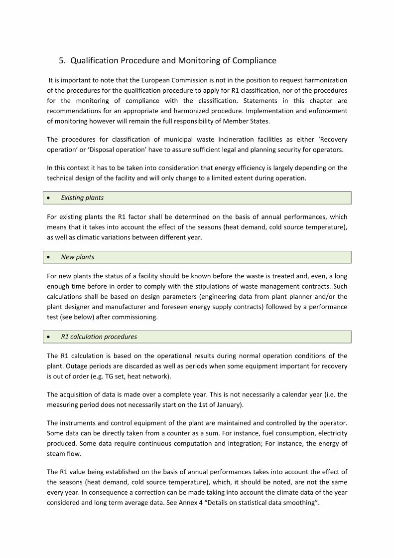
5. Qualification Procedure and Monitoring of Compliance
It is important to note that the European Commission is not in the position to request harmonization of the procedures for the qualification procedure to apply for R1 classification, nor of the procedures for the monitoring of compliance with the classification. Statements in this chapter are recommendations for an appropriate and harmonized procedure. Implementation and enforcement of monitoring however will remain the full responsibility of Member States.
The procedures for classification of municipal waste incineration facilities as either ‘Recovery operation’ or ‘Disposal operation’ have to assure sufficient legal and planning security for operators.
In this context it has to be taken into consideration that energy efficiency is largely depending on the technical design of the facility and will only change to a limited extent during operation.
• Existing plants
For existing plants the R1 factor shall be determined on the basis of annual performances, which means that it takes into account the effect of the seasons (heat demand, cold source temperature), as well as climatic variations between different year.
• New plants
For new plants the status of a facility should be known before the waste is treated and, even, a long enough time before in order to comply with the stipulations of waste management contracts. Such calculations shall be based on design parameters (engineering data from plant planner and/or the plant designer and manufacturer and foreseen energy supply contracts) followed by a performance test (see below) after commissioning.
• R1 calculation procedures
The R1 calculation is based on the operational results during normal operation conditions of the plant. Outage periods are discarded as well as periods when some equipment important for recovery is out of order (e.g. TG set, heat network).
The acquisition of data is made over a complete year. This is not necessarily a calendar year (i.e. the measuring period does not necessarily start on the 1st of January).
The instruments and control equipment of the plant are maintained and controlled by the operator. Some data can be directly taken from a counter as a sum. For instance, fuel consumption, electricity produced. Some data require continuous computation and integration; For instance, the energy of steam flow.
The R1 value being established on the basis of annual performances takes into account the effect of the seasons (heat demand, cold source temperature), which, it should be noted, are not the same every year. In consequence a correction can be made taking into account the climate data of the year considered and long term average data. See Annex 4 “Details on statistical data smoothing”.

Uncertainties on the measurements and their overall effect on the R1 value can be calculated. As in the EN 12952‐15 standard, Section 9.6.3, and the FDBR guideline, § 7.3.1, p. 33 (see annex 3) for guaranteed performance, the R1 criteria is satisfied on the condition that:
R1 calculated with measured and corrected data + Overall uncertainty = R1 threshold where ‘R1 threshold’ value is 0.6 for existing plants and 0.65 for new plants.
An exemplary calculation of the R1 factor is provided in Annex 5 (draft needs to be revised).
• Revision of monitoring results/ verification of R1 status
For application of R1 classification plant operators provide to the competent authority the data required to calculate the R1 value and the R1 value calculated.
The competent authority verifies and approves the calculation sheet and requests further information or independent control measurements if needed.
When the calculated R1 value is above or equal to the threshold, within three months, issues a certificate attesting that the plant complies with the R1 formula condition.
As the calculated value of the R1 factor for year ‘n’ has been adjusted in reference to long term average climate conditions, it is not necessary to repeat the test every year.
The operator shall annually report on the activity of its plant with main data:
Waste incinerated, electricity generated, heat used outside the incinerator facility. For the additional energy flows lump sum data based on the previous R1 formula calculation of the plant might be used, in the context of reporting under Art 12(2) of the WI Directive.
Testing is to be repeated after maximum 10 years or in case of a substantial change of the basic conditions on which the first verification was based (in such a way that the R1 value may be reduced): modification on boiler, turbine generator, heat supply contract, possibly the flue gas cleaning system.
The R1/D10 status should be confirmed by the waste authority every year. This validation shall be based on routine operator`s monitoring results (annual report to authorities) and a check whether any structural changes occurred during the past year (e.g. technical modification, change of customers, etc.). If not, the installation can keep its R1/D10 status without any recalculations.
If necessary, or in case of doubts, the authorities have the right to send inspectors or to ask for any additional calculations/measurements they need.

• Transitional periods, new application
In case, the E‐parameter change due to circumstances which cannot be influenced by the plant operator (e.g. the loss of industrial heat consumer) the R1 status of a MWI plant with not be withdrawn immediately. The plant operator will be authorized by means of derogation to adjust/remediate the efficiency ratio to comply with the thresholds again until the annual reporting deadline in the following year.
Short time decrease of energy production or energy consumption will not be taken into consideration.
When a plant cannot reach the R1 status or loses it, the operator can try again by applying for new test, after documentation of procedural changes or changed energy supply contracts.
• Communication on R1 status in the context of transboundary shipments
A valid permit is a prerequisite for transboundary movement. The procedural requirements of the waste shipment regulation should apply for R1 MSWI as for any other facility. The Commission should make the data available to the public. Involved authorities shall take into account the R1 classification of receiving plants in its decision.

ANNEX 1: System Boundaries of R1 Formula
(Source: CEWEP‐ESWET‐FEAD Proposal for a Guideline for the use of the R1 energy efficiency formula for incineration facilities dedicated to the processing of Municipal Solid Waste (Waste Framework Directive 2008/98/EC, Annex II, R1 formula), 30 Nov 2009.

ANNEX 2: Typical examples for Incineration facility energy self‐use to be counted in Ep
Electricity
Turbo compressors
Electrical systems (pumps, motors, fans, compressors, trace heating, control systems etc.),
Buildings and infrastructure (e.g. illumination, air conditioning etc.)
Heat (Steam/Warm Water)
Soot blowers
NH4OH injection with steam
Pre-heating of the air
Pre-heating of feed water
Heating of water/steam cycle
Reheating of the condensate from the air cooled condenser
Steam trace heating
Re-heating of flue-gas (before catalytic reactor, after scrubber, before fabric filter)
Concentration processes (salt concentration, spray drier)
Apparatus, silos and buildings heating incl. warm water feed
Administration, social buildings, other constructions

Optional annex, comments invited about need to have it in
ANNEX 4: Long term statistical data smoothing (Source: CEWEP‐ESWET‐FEAD Proposal for a Guideline for the use of the R1 energy efficiency formula for incineration facilities dedicated to the processing of Municipal Solid Waste (Waste Framework Directive 2008/98/EC, Annex II, R1 formula), April 2010)
1.1.1.1 Weather statistical data reference
In order to avoid that the R1 value depends on the weather and thus varies from one year to another, some of the data can be smoothed by comparison with long term statistical data on local weather. ‘Long term’ is typically 30 years but it can be longer if data are available or shorter if not. Periods shorter than 10 years should be avoided as far as possible since it may generate sampling bias. The weather data (T and HDD, see below) are the ones of the site. The weather statistical data source can be :
• Either measurements systematically made on site
• Or measurements made for instance by the District heating network nearby
• Or data provided by a weather forecast centre, either in the area of the installation or obtained by interpolation (developed by JRC‐Ispra?)
1.1.1.2 Heat smoothing
The heat demand is quantified by indices called HDD (Heating Degree Days) derived from daily temperature observations (directly proportional). The European formula is described as follows by Eurostat7. “Heating degree days express the severity of the cold in a specific time period taking into consideration outdoor temperature and room temperature.
To establish a common and comparable basis, Eurostat uses the following method for the calculation of heating degree days
(18 °C ‐ Tm) x d if T
m is lower than or equal to 15 °C (heating threshold)
and are nil if Tm is greater than 15 °C
where Tm is the mean ((T
min + T
max)/ 2) outdoor temperature over a period of d days.
Calculations are executed on a daily basis (d=1), added up to a calendar month ‐ and subsequently to a year ‐ and published for each Member State separately.
Actual heating degree days based on the Eurostat methodology are calculated by the Joint Research Centre at regional (NUTS 2), national and European level.
Respectively, relative heating degree days (dt) are defined as the ratio of
7 Eurostat : ‘Statistics in focus — Environment and energy — 5/2006’, p. 4. Download : http://epp.eurostat.ec.europa.eu/cache/ITY_OFFPUB/KS-NQ-06-005/EN/KS-NQ-06-005-EN.PDF

Actual degree days
Long‐term average degree days”
This figure shows the ratio between the annual EU‐25 average HDD value of year in abscissa and the long term (25 year, 1980 to 2004) average HDD value. It can be seen on it that the average HDD value of a particular year can be up to 12% above the long term average (e.g. in 1985) or 8% below (e.g. in 2000). The heat supplied to a District heating network or for other heating purpose during year n, Qheat, n can be corrected taking into account the annual HDD of year n, HDDn, and the long term average HDD, e.g. HDD30y.
This is done proportionally : Qheat, n corrected = Qheat, n measured x (HDD30y / HDDn)
Heat directly used by an industry (not via District Heating) is in general not to be corrected like that. Correction parameters and formula may be provided by the industry if relevant. In general there is no correction for the heat used by the incineration process itself.
The correction on heat can be done as well for CHP plants (Combined Heat and Power): Although a reduction in heat demand (resulting from lower HDD) may lead to an increased part of the energy being turned into electricity, the electricity cycle will be reduced since the temperature is higher.
1.1.1.3 Electricity smoothing
In Waste‐to‐Energy plants equipped with a condensing turbine, the cold source of the cycle generating electricity is usually provided by an air condenser and therefore the atmospheric ambient air temperature is critical.
The annual average ambient air temperature of the considered year n, Tair n can be compared to the average value over the past reference years, e.g. the past 30 years, Tair 30y.
The electricity generated by the alternator during year ‘n’ may thus be corrected taking into account the average ambient air temperature over the year and the average ambient temperature over 30 years. This may be done according to the curve provided by the manufacturer for the performance tests which gives the electrical output of the TG set in function of the ambient temperature.
For condensing turbines with an extraction supplying steam to a third party such as a district heating, it will usually be enough to make a correction on the heat (see previous §).

ANNEX 5: Example for the determination of the R1 energy efficiency factor
(Source: Draft Guidance for the determination of the energy efficiency factor R1 (Waste Framework Directive 2000/98/EC, Annex II, R1 formula elaborated by ITAD in coordination with the German Environment Ministry and the Environment Agency, May 2009)
## alternative exemplary calculations would be appreciated (draft)
status 2007
Type of energy unit amount [Mg(tonne)]
NCV [kJ/kg] energy Ex [MWh]
1.1 amount of incinerated waste (without 1.2 and 1.3) 701.182 10.264 1.999.148 1.2 e.g. amount of incinerated sewage sludge 0 0 1.3 e.g. amount used activated carbon incinerated 0 0
1 Ew: energy input to the system by waste MWh 1.999.148
2.1 Ef 1: amount of light fuel oil for start up (after connection with the steam grid) liter 335.834 42.000 3.370
2.2 Ef 2: amount of light fuel oil for keeping the incineration temperature liter 323.193 42.000 3.243
2.3 Ef 3: amount of natural gas for start up and keeping incineration temperature Nm3 0
2 S Ef: energy input by imported energy with steam production MWh 6.612
3.1 Ei 1: amount of light fuel oil for start up/shut down (no connection with the steam grid) liter 111.945 42.000 1.123
3.2 Ei 2: e.g. natural gas for heating up of flue gas temperature for SCR Nm3 0 0
3.3 Ei 3: imported electricity (multiplided with the equivalence factor 2.6) 0 0
3.4 Ei 4: imported heat (multiplided with the equivalence factor 1.1) 0 0
3 S Ei: energy input by imported energy without steam production MWh 1.123
4.1 Epel internal used: electricity produced and internally used for the incineration process MWh 82.807
4.2 Epel exported: electricity delivered to a third party MWh 339.982

4 S Epel produced = Epel internal used + Epel exported MWh 422.789
amount [Mg]
net enthalpy ∆c [kJ/kg]
energy Ex [MWh]
5.1 Epheat exp.1: steam delivered to a third party without backflow as condensate 11.750 3.023 9.867
5.2 Epheat exp.2: district heat delivered to a third party with backflow as condensate (hot water) 71.445
5 S Epheat exported = Epheat exp.1 + Epheat exp.2 MWh 81.312
6.1 Epheat int.used1: for steam driven turbo pumps for boiler water, backflow as steam 42.831 397 4.723
6.2 Epheat int.used2: for heating up of flue gas with steam, backflow as condensate 120.404 2.225 74.416
6.3 Epheat int.used3: for heating up combustion air with steam, backflow as condensate 66.225 2.606 47.940
6.4 Epheat int.used4: for concentration of liquid APC residues with steam, backflow as condensate 23.863 2.730 18.097
6.5 Epheat int.used5: for soot blowing without backflow as steam or condensate 38.026 2.918 30.822
6.6 Epheat int.used6: for deaeration and heating up of condensate, input as boiler (feed) water 211.343 2.499 146.679
6.7 Epheat int.used7: for heating purposes of buildings/instrumentes/silos, backflow as condensate 23.638 2.490 16.351
6.8 Epheat int.used8: for deaeration‐demineralization with condensate as boiler water input 21.972 2.699 16.475
6.9 Epheat int.used9: for NH4OH (water) injection without backflow as steam or condensate 10.517 2.918 8.525
6 S Epheat int.used = S Epheat int.used1‐9 MWh 364.027
R1 = (Ep ‐ (Ef + Ei)) / (0.97 * (Ew + Ef)) [‐]
Ep = 2.6*(S Epel int.used+S Epel exported) + 1.1*(S Epheat int.used+S Epheat exported) MWh 1.589.124
R1 = ((2.6*(422,789) + 1.1*(445,339)) ‐ (6,612+1,123))/(0.97*(1,999,148+6,612) [‐] 0,81
Remarks:
to 2.1 Amount of light fuel oil (ρlfoil = 0,86 kg/liter) during start up/shut down with steam production, determined from the light fuel oil demand
during the relevant time period: connected to the steam grid but yet without release of waste into the furnace.
to Amount of light fuel oil (ρlfoil = 0,86 kg/liter) with steam production, during the relevant time period: keeping incineration temperature.

2.2
to 3.1 Determined as difference out of total light fuel oil demand minus demand by 2.1 and 2.2. to 5.1 In this example there is no backflow of condensate, therefore difference of enthalpy equal to the enthalpy of middle pressure (mp) steam
(advice: in case of backflow of condensate Dc is the difference out of enthalpy from delivered steam minus enthalpy of condensate). to 5.2 Amount of district heat determined from the quantity of transported hot water (deviation concerning the steam quantity about 3%). to 6.1 Steam driven turbo pumps for boiler water using high pressure (hp) steam, decompressing to low pressure (lp) steam; ∆c = 397 kJ/kg. to 6.2 Heat exchangers for heating up flue gas are operated with middle (mp) pressure steam (13 bar). Depending on the fouling of the heat
exchangers and throughput, so that the steam pressure is in the range of 9‐12 bar. Only the difference of enthalpy, that means the enthalpy
of mp steam (as average 10 bar) with backflow of the condensate into the condensate collecting tank (3.2 bar) and therefore
on energy losses are taken into account (in the condensate collecting tank decompression to lp steam, which goes into the lp steam net). to 6.3 Heat exchangers for combustion air are fed with mp steam and are operated at about 1 bar. The condensate goes back into the condensate
collecting tank (100°C), therefore ∆c = 3,023 ‐ 100 *4,18 = 2,606 kJ/kg . to 6.4 Liquid APC residues are treated with mp steam, condensate at 70°C flows back into the boiler (feed) water tank. to 6.5 Hp steam used for soot blowing with an energy demand of ∆c = 3,211 ‐ 293 = 2,918 kJ/kg (see also NCV calculation, Annex III).
Amount of energy used for soot blowing taking part in the hp steam production was neglected. to 6.6 For deaeration and heating up of condensate for boiler (feed) water reason lp steam with 2,783 kJ/kg is used which commutes in this
process steam to boiler water with a temperature of 122°C (2.1 bar). Incomming temperature of the different mixed condensates is about 68°C. to 6.7 Heating of buildings e.g. administration, boiler houses and other sectors of the WtE plant as well as preparation of warm water
for sanitary demand is processed by heat exchangers with lp steam. Backflow of condensate at about 70°C. to 6.8 Temperature of fresh water from the demineralization installation about 20°C. to 6.9 NH4OH injection with hp steam.