Embed Size (px)
Citation preview

Document No.: M-W3334AE-43.0
ANRITSU CORPORATION
MS2830A Signal Analyzer
Operation Manual Mainframe Operation
For safety and warning information, please read this manual before attempting to use the equipment. Keep this manual with the equipment.
43rd Edition

ii
Safety Symbols To prevent the risk of personal injury or loss related to equipment malfunction, Anritsu Corporation uses the following safety symbols to indicate safety-related information. Ensure that you clearly understand the meanings of the symbols BEFORE using the equipment. Some or all of the following symbols may be used on all Anritsu equipment. In addition, there may be other labels attached to products that are not shown in the diagrams in this manual.
Symbols used in manual This indicates a very dangerous procedure that could result in serious injury or death if not performed properly. This indicates a hazardous procedure that could result in serious injury or death if not performed properly. This indicates a hazardous procedure or danger that could result in light-to-severe injury, or loss related to equipment malfunction, if proper precautions are not taken.
Safety Symbols Used on Equipment and in Manual The following safety symbols are used inside or on the equipment near operation locations to provide information about safety items and operation precautions. Ensure that you clearly understand the meanings of the symbols and take the necessary precautions BEFORE using the equipment.
This indicates a prohibited operation. The prohibited operation is indicated symbolically in or near the barred circle.
This indicates an obligatory safety precaution. The obligatory operation is
indicated symbolically in or near the circle. This indicates a warning or caution. The contents are indicated symbolically in or
near the triangle. This indicates a note. The contents are described in the box. These indicate that the marked part should be recycled.
MS2830A Signal Analyzer Operation Manual Mainframe Operation 15 December 2009 (First Edition) 31 July 2020 (43rd Edition) Copyright © 2009-2020, ANRITSU CORPORATION. All rights reserved. No part of this manual may be reproduced without the prior written permission of the publisher. The operational instructions of this manual may be changed without prior notice. Printed in Japan
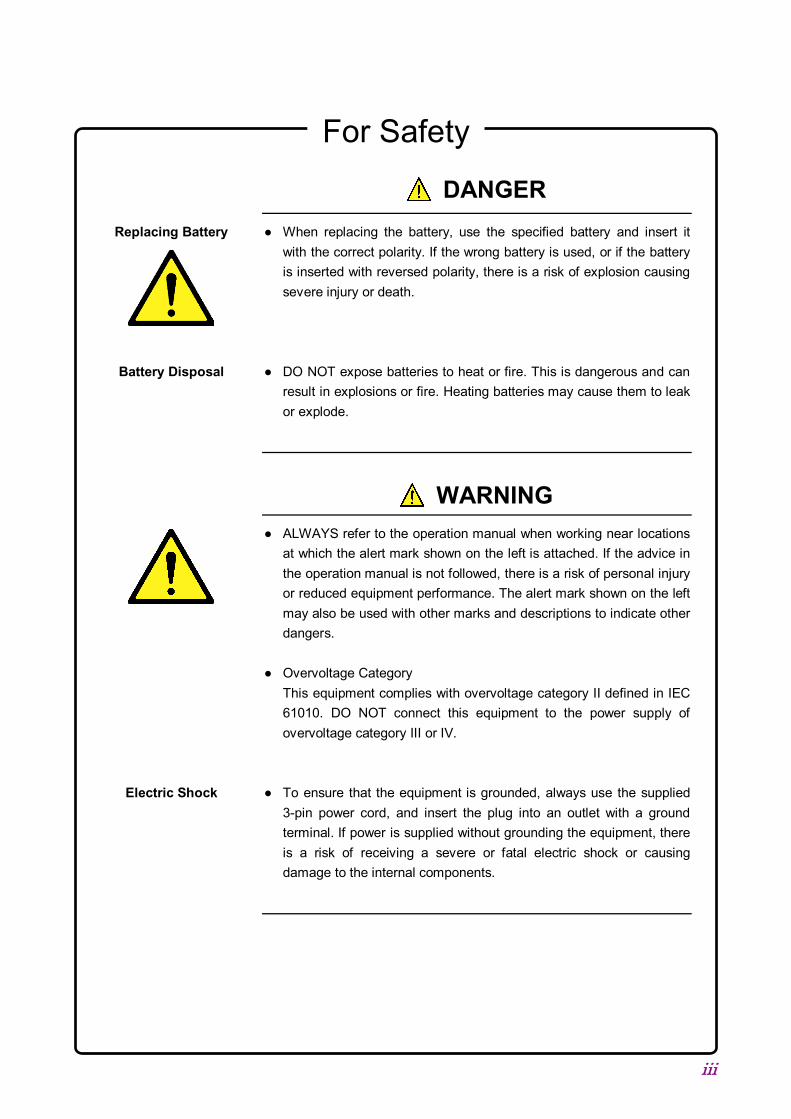
DANGER
WARNING
CAUTION
For Safety
iii
DANGER When replacing the battery, use the specified battery and insert it
with the correct polarity. If the wrong battery is used, or if the battery is inserted with reversed polarity, there is a risk of explosion causing severe injury or death.
DO NOT expose batteries to heat or fire. This is dangerous and can
result in explosions or fire. Heating batteries may cause them to leak or explode.
WARNING ALWAYS refer to the operation manual when working near locations
at which the alert mark shown on the left is attached. If the advice in the operation manual is not followed, there is a risk of personal injury or reduced equipment performance. The alert mark shown on the left may also be used with other marks and descriptions to indicate other dangers.
Overvoltage Category
This equipment complies with overvoltage category II defined in IEC 61010. DO NOT connect this equipment to the power supply of overvoltage category III or IV.
To ensure that the equipment is grounded, always use the supplied
3-pin power cord, and insert the plug into an outlet with a ground terminal. If power is supplied without grounding the equipment, there is a risk of receiving a severe or fatal electric shock or causing damage to the internal components.
Replacing Battery
Battery Disposal
Electric Shock

For Safety
iv
WARNING Only qualified service personnel with a knowledge of electrical fire and
shock hazards should service this equipment. This equipment cannot be repaired by the operator. DO NOT attempt to remove the equipment covers or unit covers or to disassemble internal components. There are high-voltage parts in this equipment presenting a risk of severe injury or fatal electric shock to untrained personnel. In addition, there is a risk of damage to precision components.
The performance-guarantee seal verifies the integrity of the
equipment. To ensure the continued integrity of the equipment, only Anritsu service personnel, or service personnel of an Anritsu sales representative, should break this seal to repair or calibrate the equipment. Be careful not to break the seal by opening the equipment or unit covers. If the performance-guarantee seal is broken by you or a third party, the performance of the equipment cannot be guaranteed.
Repair
Calibration
For Safety
v
WARNING This equipment should always be positioned in the correct manner. If
the cabinet is turned on its side, etc., it will be unstable and may be damaged if it falls over as a result of receiving a slight mechanical shock. Always set up the equipment in a position where the power switch can be reached without difficulty.
DO NOT short the battery terminals and never attempt to disassemble
the battery or dispose of it in a fire. If the battery is damaged by any of these actions, the battery fluid may leak.
This fluid is poisonous. DO NOT touch the battery fluid, ingest it, or get in your eyes. If it is accidentally ingested, spit it out immediately, rinse your mouth with water and seek medical help. If it enters your eyes accidentally, do not rub your eyes, rinse them with clean running water and seek medical help. If the liquid gets on your skin or clothes, wash it off carefully and thoroughly with clean water.
This equipment uses a Liquid Crystal Display (LCD). DO NOT subject
the equipment to excessive force or drop it. If the LCD is subjected to strong mechanical shock, it may break and liquid may leak. This liquid is very caustic and poisonous. DO NOT touch it, ingest it, or get in your eyes. If it is ingested accidentally, spit it out immediately, rinse your mouth with water and seek medical help. If it enters your eyes accidentally, do not rub your eyes, rinse them with clean running water and seek medical help. If the liquid gets on your skin or clothes, wash it off carefully and thoroughly with soap and water.
Falling Over
Battery Fluid
LCD

For Safety
vi
CAUTION Always remove the main power cable from the power outlet before
cleaning dust around the power supply and fan. - Clean the power inlet regularly. If dust accumulates around the
power pins, there is a risk of fire. - Keep the cooling fan clean so that the ventilation holes are not
obstructed. If the ventilation is obstructed, the cabinet may overheat and catch fire.
Never input a signal of more than the indicated value between the
measured terminal and ground. Input of an excessive signal may damage the equipment.
Cleaning
Check Terminal

For Safety
vii
CAUTION This equipment uses a Poly-carbon monofluoride lithium battery to backup the memory. This battery must be replaced by service personnel when it has reached the end of its useful life; contact the Anritsu sales section or your nearest representative.
Note: The battery used in this equipment has a maximum useful life of 7 years. It should be replaced before this period has elapsed.
This equipment uses USB flash drive as external storage media for storing data and programs. If this media is mishandled or becomes faulty, important data may be lost. It is recommended to periodically back up all important data and programs to protect them from being lost accidentally. Anritsu will not be held responsible for lost data. Pay careful attention to the following points. Never remove the USB flash drive from the equipment while it is
being accessed. The USB flash drive may be damaged by static electric charges. Anritsu has thoroughly tested all external storage media shipped with
this equipment. Users should note that external storage media not shipped with this equipment may not have been tested by Anritsu, thus Anritsu cannot guarantee the performance or suitability of such media.
Replacing Memory Back-up Battery
External Storage Media

For Safety
viii
CAUTION
The equipment is equipped with an internal hard disk from which, as with any hard disk, data may be lost under certain conditions. It is recommended to periodically back up all important data and programs to protect them from being lost accidentally. Anritsu will not be held responsible for lost data. To reduce the possibility of data loss, particular attention should be given to the following points. The equipment should only be used within the recommend
temperature range, and should not be used in locations where the temperature may fluctuate suddenly.
Always follow the guidelines to ensure that the equipment is set up in the specified manner.
Always ensure that the fans at the rear and side of the equipment are not blocked or obstructed in any way.
Exercise care not to bang or shake the equipment whilst the power is on.
Never disconnect the mains power at the plug or cut the power at the breaker with the equipment turned on.
This equipment is designed for an industrial environment. In a residential environment this equipment may cause radio interference in which case the user may be required to take adequate measures. Exposure to corrosive gases such as hydrogen sulfide, sulfurous acid, and hydrogen chloride will cause faults and failures. Note that some organic solvents release corrosive gases.
Hard disk
Use in a Residential Environment
Use in Corrosive Atmospheres

ix
Equipment Certificate Anritsu Corporation certifies that this equipment was tested before shipment using calibrated measuring instruments with direct traceability to public testing organizations recognized by national research laboratories, including the National Institute of Advanced Industrial Science and Technology, and the National Institute of Information and Communications Technology, and was found to meet the published specifications.
Anritsu Warranty Anritsu Corporation will repair this equipment free-of-charge if a malfunction occurs within one year after shipment due to a manufacturing fault, and software bug fixes will be performed in accordance with the separate Software End-User License Agreement, provide, however, that Anritsu Corporation will deem this warranty void when: The fault is outside the scope of the warranty conditions separately
described in the operation manual. The fault is due to mishandling, misuse, or unauthorized modification or
repair of the equipment by the customer. The fault is due to severe usage clearly exceeding normal usage. The fault is due to improper or insufficient maintenance by the customer. The fault is due to natural disaster, including fire, wind or flood,
earthquake, lightning strike, or volcanic ash, etc. The fault is due to damage caused by acts of destruction, including civil
disturbance, riot, or war, etc. The fault is due to explosion, accident, or breakdown of any other
machinery, facility, or plant, etc. The fault is due to use of non-specified peripheral or applied equipment
or parts, or consumables, etc. The fault is due to use of a non-specified power supply or in a
non-specified installation location. The fault is due to use in unusual environments(Note). The fault is due to activities or ingress of living organisms, such as
insects, spiders, fungus, pollen, or seeds. In addition, this warranty is valid only for the original equipment purchaser. It is not transferable if the equipment is resold. Anritsu Corporation shall assume no liability for damage or financial loss of the customer due to the use of or a failure to use this equipment, unless the damage or loss is caused due to Anritsu Corporation’s intentional or gross negligence.

x
Note: For the purpose of this Warranty, "unusual environments" means use: In places of direct sunlight In dusty places Outdoors In liquids, such as water, oil, or organic solvents, and medical fluids, or
places where these liquids may adhere In salty air or in place chemically active gases (sulfur dioxide, hydrogen
sulfide, chlorine, ammonia, nitrogen dioxide, or hydrogen chloride etc.) are present
In places where high-intensity static electric charges or electromagnetic fields are present
In places where abnormal power voltages (high or low) or instantaneous power failures occur
In places where condensation occurs In the presence of lubricating oil mists In places at an altitude of more than 2,000 m In the presence of frequent vibration or mechanical shock, such as in
cars, ships, or airplanes
Anritsu Corporation Contact In the event of this equipment malfunctions, please contact an Anritsu Service and Sales office. Contact information can be found on the last page of the printed version of this manual, and is available in a separate file on the PDF version.

xi
Notes On Export Management This product and its manuals may require an Export License/Approval by the Government of the product's country of origin for re-export from your country. Before re-exporting the product or manuals, please contact us to confirm whether they are export-controlled items or not. When you dispose of export-controlled items, the products/manuals need to be broken/shredded so as not to be unlawfully used for military purpose.
Trademark and Registered Trademark IQproducerTM is a registered trademark of Anritsu Corporation in the United States and/or other countries.
Lifetime of Parts The life span of certain parts used in this instrument is determined by the operating time or the power-on time. Due consideration should be given to the life spans of these parts when performing continuous operation over an extended period. These parts must be replaced at the customer's expense even if within the guaranteed period described in Warranty at the beginning of this manual. For details on life span, refer to the corresponding section in this manual. Example: Display backlight, internal hard disk, removable hard disk, connector for hard disk, cooling fan

xii
Crossed-out Wheeled Bin Symbol Equipment marked with the Crossed-out Wheeled Bin Symbol complies with council directive 2012/19/EU (the “WEEE Directive”) in European Union.
For Products placed on the EU market after August 13, 2005, please contact your local Anritsu representative at the end of the product's useful life to arrange disposal in accordance with your initial contract and the local law.

xiii
Software End-User License Agreement (EULA) Please carefully read and accept this Software End-User License Agreement (hereafter this EULA) before using (includes executing, copying, installing, registering, etc.) this Software (includes programs, databases, scenarios, etc., used to operate, set, etc., Anritsu electronic equipment, etc.). By using this Software, you shall be deemed to have agreed to be bound by the terms of this EULA, and Anritsu Corporation (hereafter Anritsu) hereby grants you the right to use this Software with the Anritsu specified equipment (hereafter Equipment) for the purposes set out in this EULA. Article 1. Grant of License and Limitations
1. You may not to sell, transfer, rent, lease, lend, disclose, sublicense, or otherwise distribute this Software to third parties, whether or not paid therefor.
2. You may make one copy of this Software for backup purposes only.
3. You are not permitted to reverse engineer, disassemble, decompile, modify or create derivative works of this Software.
4. This EULA allows you to install one copy of this Software on one piece of Equipment.
Article 2. Disclaimers To the extent not prohibited by law, in no
event shall Anritsu be liable for direct, or any incidental, special, indirect or consequential damages whatsoever, including, without limitation, damages for loss of profits, loss of data, business interruption or any other commercial damages or losses, and damages claimed by third parties, arising out of or related to your use or inability to use this Software, unless the damages are caused due to Anritsu’s intentional or gross negligence.
Article 3. Limitation of Liability
1. If a fault (bug) is discovered in this Software, failing this Software to operate as described in the operation manual or specifications even though you have used this Software as described in the manual, Anritsu shall at its own discretion, fix the bug, or replace the software, or suggest a workaround, free-of-charge, provided, however, that the faults caused by the following items and any
of your lost or damaged data whatsoever shall be excluded from repair and the warranty.
i) If this Software is deemed to be used for purposes not described in the operation manual or specifications.
ii) If this Software has been used in conjunction with other non-Anritsu-approved software.
iii) If this Software or the Equipment has been modified, repaired, or otherwise altered without Anritsu's prior approval.
iv) For any other reasons out of Anritsu's direct control and responsibility, such as but not limited to, natural disasters, software virus infections, or any devices other than this Equipment, etc.
2. Expenses incurred for transport, hotel, daily allowance, etc., for on-site repairs or replacement by Anritsu engineers necessitated by the above faults shall be borne by you.
3. The warranty period for faults listed in Section 1 of this Article shall be either 6 months from the date of purchase of this Software or 30 days after the date of repair or replacement, whichever is longer.

xiv
Article 4. Export Restrictions You shall not use or otherwise export or
re-export directly or indirectly this Software except as authorized by the laws and regulations of Japan and the United States, etc. In particular, this Software shall not be exported or re-exported (a) into any Japan or US embargoed countries or (b) to anyone restricted by the Japanese export control regulations, or the US Treasury Department's list of Specially Designated Nationals or the US Department of Commerce Denied Persons List or Entity List. In using this Software, you warrant that you are not located in any such embargoed countries or on any such lists. You also agree that you will not use or otherwise export or re-export this Software for any purposes prohibited by the Japanese and US laws and regulations, including, without limitation, the development, design and manufacture or production of missiles or nuclear, chemical or biological weapons of mass destruction, and conventional weapons.
Article 5. Change of Terms Anritsu may change without your approval
the terms of this EULA if the changes are for the benefit of general customers, or are reasonable in light of the purpose of this EULA and circumstances of the changes. At the time of change, Anritsu will inform you of those changes and its effective date, as a general rule 45 days, in advance on its website, or in writing or by e-mail.
Article 6. Termination 1. Anritsu may terminate this EULA
immediately if you violate any conditions described herein. This EULA shall also be terminated immediately by Anritsu if there is any good reason that it is deemed difficult to continue this EULA, such as your violation of Anritsu copyrights, patents, etc. or any laws and ordinances, or if it turns out that you belong to an antisocial organization
or has a socially inappropriate relationship with members of such organization.
2. You and Anritsu may terminate this EULA by a written notice to the other party 30 days in advance.
Article 7. Damages If Anritsu suffers any damages or loss,
financial or otherwise, due to your violation of the terms of this EULA, Anritsu shall have the right to seek proportional damages from you.
Article 8. Responsibility after Termination Upon termination of this EULA in
accordance with Article 6, you shall cease all uses of this Software immediately and shall as directed by Anritsu either destroy or return this Software and any backup copies, full or partial, to Anritsu
Article 9. Negotiation for Dispute Resolution
If matters of interpretational dispute or items not covered under this EULA arise, they shall be resolved by negotiations in good faith between you and Anritsu.
Article 10. Governing Law and Court of Jurisdiction
This EULA shall be governed by and interpreted in accordance with the laws of Japan without regard to the principles of the conflict of laws thereof, and any disputes arising from or in relation to this EULA that cannot be resolved by negotiation described in Article 9 shall be subject to and be settled by the exclusive agreed jurisdiction of the Tokyo District Court of Japan.
Revision History:
February 29th, 2020
xv
Using VISA Driver for Remote Control of This Equipment
When controlling this measuring equipment remotely using the Ethernet port, a VISA*1 driver must be installed in the PC controller. We recommend using NI-VISA™*2 from National Instruments™ (NI hereafter) as the VISA driver. Although a license is generally required to use NI-VISA™, the licensed NI-VISA™ driver is provided free-of-charge for use when performing remote control (Note) of this measuring equipment. The NI-VISA™ driver can be downloaded from the NI website at:
http://sine.ni.com/psp/app/doc/p/id/psp-411
Be sure to comply with the NI license agreement for the usage and license scope. Be sure to uninstall the NI-VISA™ driver when disposing of this measuring equipment or transferring it to a third party, etc., when ceasing to use NI-VISA™, or upon completion of the contract term when using this equipment on a rental contract.
(Notes) Although the NI-VISA™ driver itself can be downloaded free-of-charge from the web, an implementation license is required for legal reasons when some requirements are not met. (Check the NI web page for the detailed requirements.) If these requirements are not met, permission is not granted to use NI hardware and software and an NI implementation license must be purchased. However, since this measuring equipment incorporates NI hardware (GPIB ASIC), the NI-VISA™ driver can be downloaded and used free-of-charge.
Glossary of Terms:
*1: VISA: Virtual Instrument Software Architecture I/O software specification for remote control of measuring
instruments using interfaces such as GPIB, Ethernet, USB, etc. *2: NI-VISA™ World de facto standard I/O software interface developed by NI
and standardized by the VXI Plug&Play Alliance. Trademarks:
- National Instruments™, NI™, NI-VISA™ and National Instruments Corporation are all trademarks of National Instruments Corporation.
xvi
Cautions Against Computer Virus Infection Copying files and data Only files that have been provided directly from Anritsu or generated
using Anritsu equipment should be copied to the instrument. All other required files should be transferred by means of USB flash
drive or CompactFlash media after undergoing a thorough virus check.
Adding software Do not download or install software that has not been specifically
recommended or licensed by Anritsu. Network connections Ensure that the network has sufficient anti-virus security protection in
place. Protection against malware (malicious software such as viruses). This equipment runs on Windows Operating System. To connect this equipment to network, the following is advised.
- Activate Firewall. - Install important updates of Windows. - Use antivirus software.

xvii
CE Conformity Marking Anritsu affixes the CE conformity marking on the following product(s) in accordance with the Decision 768/2008/EC to indicate that they conform to the EMC, LVD, and RoHS directive of the European Union (EU).
CE marking
1. Product Model Model: MS2830A Signal Analyzer
2. Applied Directive EMC: Directive 2014/30/EU LVD: Directive 2014/35/EU RoHS: Directive 2011/65/EU 3. Applied Standards
EMC: Emission: EN 61326-1: 2013 (Class A) Immunity: EN 61326-1: 2013 (Table 2)
Performance Criteria*
IEC 61000-4-2 (ESD) B IEC 61000-4-3 (EMF) A IEC 61000-4-4 (Burst) B IEC 61000-4-5 (Surge) B IEC 61000-4-6 (CRF) A IEC 61000-4-8 (RPFMF) A IEC 61000-4-11 (V dip/short) B, C *: Performance Criteria
A: The equipment shall continue to operate as intended during and after the test. No degradation of performance or loss of function is allowed below a performance level specified by the manufacturer, when the equipment is used as intended. The performance level may be replaced by a permissible loss of performance. If the minimum performance level or the permissible performance loss is not specified by the manufacturer, either of these may be derived from the

xviii
product description and documentation and what the user may reasonably expect from the equipment if used as intended.
B: The equipment shall continue to operate as intended after the test. No degradation of performance or loss of function is allowed below a performance level specified by the manufacturer, when the equipment is used as intended. The performance level may be replaced by a permissible loss of performance. During the test, degradation of performance is however allowed. No change of actual operating state or stored data is allowed. If the minimum performance level or the permissible performance loss is not specified by the manufacturer, either of these may be derived from the product description and documentation and what the user may reasonably expect from the equipment if used as intended.
C: Temporary loss of function is allowed, provided the
function is self-recoverable or can be restored by the operation of the controls.
Harmonic current emissions:
EN 61000-3-2: 2014 (Class A equipment) LVD: EN 61010-1: 2010 (Pollution Degree 2) • RoHS: EN 50581: 2012 (Category 9)
Serial number example
If the third digit of the serial number is "7", the product complies with Directive 2011/65/EU as amended by (EU) 2015/863. (Pb,Cd,Cr6+,Hg,PBB,PBDE,DEHP,BBP,DBP,DIBP) If the third digit of the serial number is "6", the product complies with Directive 2011/65/EU. (Pb,Cd,Cr6+,Hg,PBB,PBDE)
Third digit

xix
4. Contact Name: Anritsu GmbH Address, city: Nemetschek Haus, Konrad-Zuse-Platz 1 81829 München, Country: Germany Name: ANRITSU EMEA Ltd. Address, city: 200 Capability Green, Luton Bedfordshire, LU1 3LU Country: United Kingdom

xx
RCM Conformity Marking Anritsu affixes the RCM mark on the following product(s) in accordance with the regulation to indicate that they conform to the EMC framework of Australia/New Zealand.
RCM marking
1. Product Model
Model: MS2830A Signal Analyzer 2. Applied Standards
EMC:Emission: EN 61326-1: 2013 (Class A equipment)

xxi
About Eco label The label shown on the left is attached to Anritsu products meeting our environmental standards. Details about this label and the environmental standards are available on the Anritsu website at https://www.anritsu.com/

xxii
I
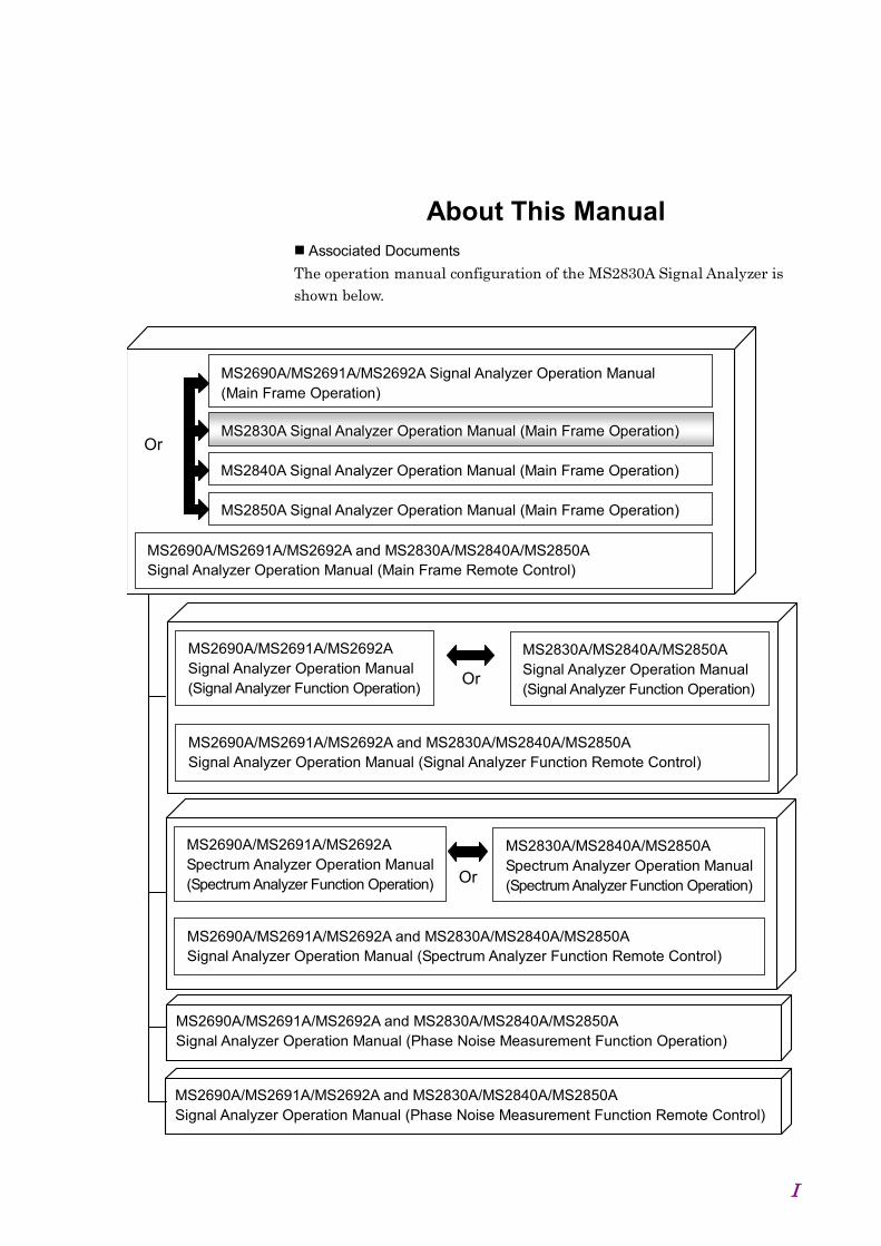
About This Manual Associated Documents The operation manual configuration of the MS2830A Signal Analyzer is shown below.
MS2690A/MS2691A/MS2692A Signal Analyzer Operation Manual (Main Frame Operation)
MS2690A/MS2691A/MS2692A and MS2830A/MS2840A/MS2850A Signal Analyzer Operation Manual (Phase Noise Measurement Function Operation)
MS2690A/MS2691A/MS2692A and MS2830A/MS2840A/MS2850A Signal Analyzer Operation Manual (Phase Noise Measurement Function Remote Control)
MS2690A/MS2691A/MS2692A and MS2830A/MS2840A/MS2850A Signal Analyzer Operation Manual (Main Frame Remote Control)
MS2830A Signal Analyzer Operation Manual (Main Frame Operation) Or
MS2850A Signal Analyzer Operation Manual (Main Frame Operation)
MS2690A/MS2691A/MS2692A Signal Analyzer Operation Manual (Signal Analyzer Function Operation)
MS2690A/MS2691A/MS2692A and MS2830A/MS2840A/MS2850A Signal Analyzer Operation Manual (Signal Analyzer Function Remote Control)
MS2830A/MS2840A/MS2850A Signal Analyzer Operation Manual (Signal Analyzer Function Operation) Or
MS2690A/MS2691A/MS2692A Spectrum Analyzer Operation Manual (Spectrum Analyzer Function Operation)
MS2690A/MS2691A/MS2692A and MS2830A/MS2840A/MS2850A Signal Analyzer Operation Manual (Spectrum Analyzer Function Remote Control)
MS2830A/MS2840A/MS2850A Spectrum Analyzer Operation Manual (Spectrum Analyzer Function Operation) Or
MS2840A Signal Analyzer Operation Manual (Main Frame Operation)

II
• Signal Analyzer Operation Manual (Mainframe) <This document> • Signal Analyzer Operation Manual (Mainframe Remote Control)
Description of basic operations, maintenance procedures, common functions and common remote functions of the mainframe
• Signal Analyzer Operation Manual (Signal Analyzer Function) • Signal Analyzer Operation Manual (Signal Analyzer Function Remote
Control) Description of basic operations, functions and remote functions of the signal analyzer
• Signal Analyzer Operation Manual (Spectrum Analyzer Function) • Signal Analyzer Operation Manual (Spectrum Analyzer Function Remote
Control) Description of basic operations, functions and remote functions of the spectrum analyzer
• Signal Analyzer Operation Manual (Phase Noise Measurement Function) • Signal Analyzer Operation Manual (Phase Noise Measurement Function
Remote Control) Description of basic operations, common functions and common remote functions of the Phase Noise Measurement function
In this document, indicates a panel key.

1
III
2
3
4
5
6
7
Appendix Index
8
9
Table of Contents For Safety ..................................................... iii
About This Manual ........................................ I
Overview ............................................ 1-1 Chapter 11.1 Product Overview........................................................ 1-3 1.2 Product Configuration ................................................. 1-4 1.3 Specifications............................................................ 1-11
Before Use ......................................... 2-1 Chapter 22.1 Installation Location .................................................... 2-2 2.2 Items to Check Before Use ......................................... 2-4 2.3 Power Connection ....................................................... 2-9
Common Operations ........................ 3-1 Chapter 33.1 Part Names ................................................................. 3-2 3.2 Turning Power On/Off ............................................... 3-11 3.3 Auto Calibration ........................................................ 3-14 3.4 Settings on Configuration Screen .............................. 3-17 3.5 Loading, Unloading, and Switching Applications ........ 3-34 3.6 Save and Recall Functions ........................................ 3-43 3.7 Initializing .................................................................. 3-52 3.8 Installing and Uninstalling .......................................... 3-54
Chapter 4 Tutorial ............................................... 4-1 4.1 Spectrum Analysis Using Signal Analyzer ................... 4-2 4.2 Spectrum Analysis Using Spectrum Analyzer .............. 4-6
Chapter 5 System ............................................... 5-1 5.1 Setting Windows ......................................................... 5-2 5.2 Storage Device Configuration .................................... 5-12 5.3 System Recovery Functions ...................................... 5-13 5.4 Windows Security Measures ..................................... 5-19

IV
Performance Test ............................. 6-1 Chapter 66.1 Overview of Performance Test .................................... 6-2 6.2 Performance Test Items .............................................. 6-5
Power Meter ...................................... 7-1 Chapter 77.1 Power Meter ............................................................... 7-2 7.2 Display Description ..................................................... 7-3 7.3 Function Menu ............................................................ 7-5 7.4 Initialization ............................................................... 7-15
BER Measurement Function ........... 8-1 Chapter 88.1 Outline of BER Measurement ...................................... 8-2 8.2 Display Description ..................................................... 8-5 8.3 BER Measurement Function Menu .............................. 8-9 8.4 Connecting MS2830A-026/126 to External System ... 8-11 8.5 Performing BER Measurement .................................. 8-12 8.6 Setting Automatic Resynchronization Function .......... 8-23 8.7 Setting Input Interface ............................................... 8-28 8.8 Setting PN_Fix Pattern .............................................. 8-29 8.9 Setting User-defined Pattern ..................................... 8-36 8.10 Description of BER Measurement Operation ............. 8-44
Maintenance ...................................... 9-1 Chapter 99.1 Daily Maintenance and Storage................................... 9-2 9.2 Repackaging and transporting when returning product ........... 9-4 9.3 Calibration .................................................................... 9-5

1
V
Appendix Index
8
9
2
3
4
5
6
7
Appendix A Performance Test Result Form... A-1
Appendix B Panel Keys and Keyboard Operations ....................................... B-1
Appendix C Virus Check Procedure (WES 2009) ..................................... C-1
Appendix D Virus Check Procedure (WES 7) . D-1
Appendix E Virus Check Procedure (Windows 10) .................................. E-1
Appendix F Error Messages .............................. F-1
Appendix G Initial Value List ............................ G-1
Index ........................................................... Index-1

VI.
1-1
1 O
verview
Overview Chapter 1 This chapter provides an overview of the MS2830A Signal Analyzer and product configuration.
1.1 Product Overview........................................................ 1-3 1.2 Product Configuration ................................................. 1-4
1.2.1 Standard configuration .................................... 1-4 1.2.2 Options ........................................................... 1-5 1.2.3 Applicable Parts .............................................. 1-8 1.2.4 Application Software ..................................... 1-10
1.3 Specifications............................................................ 1-11 1.3.1 Mainframe (MS2830A) .................................. 1-11 1.3.2 Rubidium Reference Oscillator Option
(MS2830A-001/101) ...................................... 1-54 1.3.3 High Stability Reference Oscillator Option
(MS2830A-002/102) ...................................... 1-54 1.3.4 Preamplifier Option (MS2830A-008/108) ....... 1-55 1.3.5 Analysis Bandwidth Extension to 31.25 MHz
Option (MS2830A-005/105) ........................ 1-56 1.3.6 Analysis Bandwidth Extension to 10 MHz Option
(MS2830A-006/106) ...................................... 1-56 1.3.7 Phase Noise Measurement Option
(MS2830A-010/110) ...................................... 1-56 1.3.8 Secondary HDD Option (MS2830A-011/111) . 1-56 1.3.9 Precompliance EMI Function
(MS2830A-016/116) ...................................... 1-56 1.3.10 Low Phase Noise Performance Option
(MS2830A-062/066) ...................................... 1-57 1.3.11 Removable HDD option (MS2830A-313) ....... 1-58 1.3.12 Microwave Preamplifier Option
(MS2830A-068/168) ...................................... 1-59 1.3.13 Microwave Preselector Bypass Option
(MS2830A-067/167) ...................................... 1-60 1.3.14 Bandwidth Extension to 31.25 MHz with
Preselector Bypass Option (MS2830A-007)... 1-62 1.3.15 Analysis Bandwidth Extension Option,
62.5 MHz (MS2830A-077/177).................... 1-63 1.3.16 Analysis Bandwidth Extension Option, 125 MHz
(MS2830A-078/178) ...................................... 1-64 1.3.17 Bandwidth Extension to 31.25 MHz for
Millimeter-wave (MS2830A-009/109) .......... 1-64 1.3.18 BER Measurement function
(MS2830A-026/126) ...................................... 1-65 1.3.19 Audio Analyzer Option (MS2830A-018/118) .. 1-66
Chapter 1 Overview
1-2
1.3.20 Two-handle Frame with Connecting Parts (for
Single-handle Frame) (MS2830A-171) ........ 1-66 1.3.21 Connecting parts (for two-handle frame)
(MS2830A-081/181) ...................................... 1-66 1.3.22 3.6 GHz Analog Signal Generator Option
(MS2830A-088/188) ...................................... 1-66 1.3.23 Vector Function Extension for Analog Signal
Generator Option (MS2830A-189) ................. 1-66 1.3.24 Internal Signal Generator Control Function
Option (MS2830A-052/152/352) ................. 1-67 1.3.25 Noise Figure Measurement Function Option
(MS2830A-017/117) ...................................... 1-67 1.3.26 Rubidium Reference Oscillator Option
(MS2830A-037/137) ...................................... 1-67

1.1 Product Overview
1-3
1 O
verview
1.1 Product Overview The MS2830A Signal Analyzer ("the MS2830A" hereafter) is a spectrum analyzer to which options such as real-time signal analysis and vector modulation analysis can be added.
The MS2830A enables high-speed and high-accuracy signal processing of wide-ranging analyses at full-span, a characteristic of conventional sweep-type spectrum analyzers, using a digital IF block. In addition, the FFT process (high-speed Fourier conversion) realizes high-speed spectrum analysis and simultaneous analysis on frequency and time axes not possible with conventional sweep-type spectrum analyzers. Also, added option enables recording of the RF input signal as digital data (digitize function). It can be used in a variety of applications from research and development to manufacturing thanks to its characteristics.
The key features are listed below:
Wide frequency band (3.6 GHz/6 GHz/13.5 GHz/26.5 GHz/43 GHz) Wide analysis bandwidth (Option 006/106: 10 MHz, Option
005/105/007/009/109: 31.25 MHz, Option 077/177: 62.5 MHz, Option 078/178: 125 MHz)
High dynamic range High-speed measurement High-speed, high-accuracy signal analysis using digital IF Enables time-continuous analysis of loaded data Large-capacity waveform memory and digitization function that
records RF signals without missing (when option 006/106, 005/105, 007, 077/177, 009/109, or 078/178 is used)
BER Measurement function (when option 026/126 is used) Rich measurement functions The MS2830A is equipped with the hardware product made by National Instruments and comes with the license for NI-VISA. NI-VISA can be used for the purpose of controlling the MS2830A.
Chapter 1 Overview
1-4
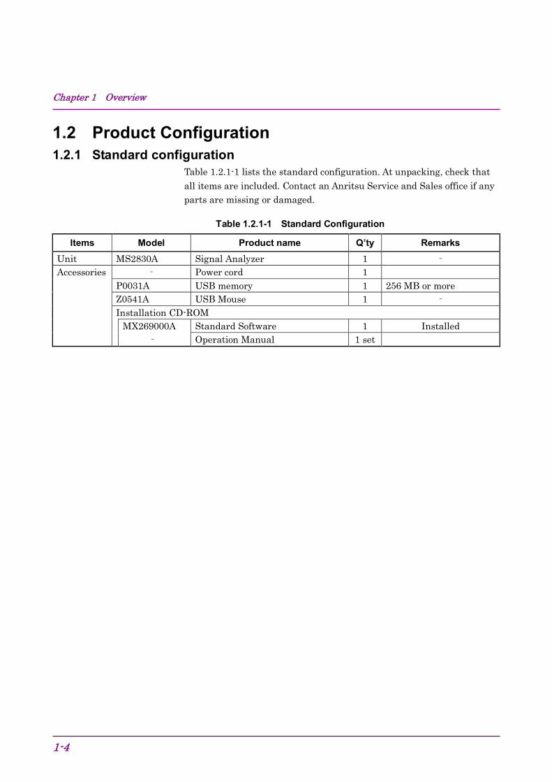
1.2 Product Configuration 1.2.1 Standard configuration
Table 1.2.1-1 lists the standard configuration. At unpacking, check that all items are included. Contact an Anritsu Service and Sales office if any parts are missing or damaged.
Table 1.2.1-1 Standard Configuration
Items Model Product name Q’ty Remarks Unit MS2830A Signal Analyzer 1 – Accessories – Power cord 1
P0031A USB memory 1 256 MB or more Z0541A USB Mouse 1 – Installation CD-ROM MX269000A Standard Software 1 Installed – Operation Manual 1 set

1.2 Product Configuration
1-5
1
Overview
1.2.2 Options Table 1.2.2-1 through Table 1.2.2-2 list the options. They are sold separately. Note:
There is a risk of losing the data when adding additional option(s), so back up the data stored on the hard disk, in advance. Anritsu is not responsible for any loss of data.
Table 1.2.2-1 Additional Options at/after shipment
Option Number Product Name Remarks MS2830A-040 3.6 GHz Signal Analyzer 9 kHz to 3.6 GHz MS2830A-041 6 GHz Signal Analyzer 9 kHz to 6 GHz MS2830A-043 13.5 GHz Signal Analyzer 9 kHz to 13.5 GHz MS2830A-044 26.5 GHz Signal Analyzer 9 kHz to 26.5 GHz MS2830A-045 43 GHz Signal Analyzer 9 kHz to 43 GHz MS2830A-001 Rubidium Reference Oscillator See Table 1.3.1-1 “Internal reference
oscillator”. MS2830A-101 Rubidium Reference Oscillator Retrofit MS2830A-002 High Stability Reference Oscillator
MS2830A-102 High Stability Reference Oscillator, Retrofit
MS2830A-037 Rubidium Reference Oscillator MS2830A-137 Rubidium Reference Oscillator Retrofit MS2830A-006 Analysis Bandwidth 10 MHz Analysis bandwidth: Max. 10 MHz MS2830A-106 Analysis Bandwidth 10 MHz, Retrofit MS2830A-005 Analysis Bandwidth Extension to
31.25 MHz Extends Analysis Bandwidth to 31.25 MHz Unavailable when MS2830A-045 is installed.
MS2830A-105 Analysis Bandwidth Extension to 31.25 MHz, Retrofit
MS2830A-007 Bandwidth Extension to 31.25 MHz with Preselector Bypass
Extends Analysis Bandwidth to 31.25 MHz Available only when MS2830A-045 is installed.
MS2830A-009 Bandwidth Extension to 31.25 MHz for Millimeter-wave
Extends Analysis Bandwidth to 31.25 MHz Available only when MS2830A-045 is installed.
MS2830A-109 Bandwidth Extension to 31.25 MHz for Millimeter-wave, Retrofit
MS2830A-077 Analysis Bandwidth Extension to 62.5 MHz
Extends Analysis Bandwidth to 62.5 MHz
MS2830A-177 Analysis Bandwidth Extension to 62.5 MHz, Retrofit
MS2830A-078 Analysis Bandwidth Extension to 125 MHz
Extends Analysis Bandwidth to 125 MHz
MS2830A-178 Analysis Bandwidth Extension to 125 MHz, Retrofit

Chapter 1 Overview
1-6
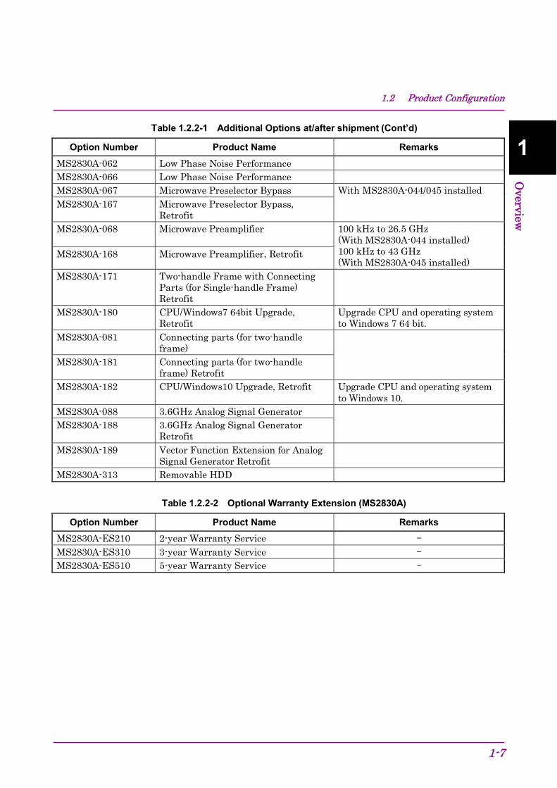
Table 1.2.2-1 Additional Options at/after shipment (Cont’d)
Option Number Product Name Remarks MS2830A-008 Preamplifier 100 kHz to 3.6 GHz (With
MS2830A-040) 100 kHz to 6 GHz (With MS2830A-041/043)
MS2830A-108 Preamplifier, Retrofit
MS2830A-010 Phase Noise Measurement Function 10 MHz to Upper frequency limit MS2830A-110 Phase Noise Measurement Function,
Retrofit
MS2830A-011 Secondary HDD MS2830A-111 Secondary HDD, Retrofit MS2830A-016 Precompliance EMI Function MS2830A-116 Precompliance EMI Function Retrofit MS2830A-017 Noise Figure Measurement Function MS2830A-117 Noise Figure Measurement Function
Retrofit
MS2830A-018 Audio Analyzer MS2830A-118 Audio Analyzer Retrofit MS2830A-020 3.6 GHz Vector Signal Generator 250 kHz to 3.6 GHz MS2830A-120 3.6 GHz Vector Signal Generator,
Retrofit
MS2830A-021 6 GHz Vector Signal Generator 250 kHz to 6 GHz MS2830A-121 6 GHz Vector Signal Generator,
Retrofit
MS2830A-022 Low Power Extension for Vector Signal Generator
Lower setting limit of output signal level: –136 dBm
MS2830A-122 Low Power Extension for Vector Signal Generator, Retrofit
MS2830A-026 BER Measurement function MS2830A-126 BER Measurement function, Retrofit MS2830A-027 ARB Memory Upgrade 256 MSample
for Vector Signal Generator
MS2830A-127 ARB Memory Upgrade 256 MSample for Vector Signal Generator, Retrofit
MS2830A-028 AWGN MS2830A-128 AWGN, Retrofit MS2830A-052 Internal Signal Generator Control
Function MS2830A-020/120/021/121/088/188 is required
MS2830A-152 Internal Signal Generator Control Function Retrofit
MS2830A-352 Internal Signal Generator Control Function User-installable
1.2 Product Configuration
1-7
1
Overview
Table 1.2.2-1 Additional Options at/after shipment (Cont’d)
Option Number Product Name Remarks MS2830A-062 Low Phase Noise Performance MS2830A-066 Low Phase Noise Performance MS2830A-067 Microwave Preselector Bypass With MS2830A-044/045 installed MS2830A-167 Microwave Preselector Bypass,
Retrofit
MS2830A-068 Microwave Preamplifier 100 kHz to 26.5 GHz (With MS2830A-044 installed) 100 kHz to 43 GHz (With MS2830A-045 installed)
MS2830A-168 Microwave Preamplifier, Retrofit
MS2830A-171 Two-handle Frame with Connecting Parts (for Single-handle Frame) Retrofit
MS2830A-180 CPU/Windows7 64bit Upgrade, Retrofit
Upgrade CPU and operating system to Windows 7 64 bit.
MS2830A-081 Connecting parts (for two-handle frame)
MS2830A-181 Connecting parts (for two-handle frame) Retrofit
MS2830A-182 CPU/Windows10 Upgrade, Retrofit Upgrade CPU and operating system to Windows 10.
MS2830A-088 3.6GHz Analog Signal Generator MS2830A-188 3.6GHz Analog Signal Generator
Retrofit
MS2830A-189 Vector Function Extension for Analog Signal Generator Retrofit
MS2830A-313 Removable HDD
Table 1.2.2-2 Optional Warranty Extension (MS2830A)
Option Number Product Name Remarks MS2830A-ES210 2-year Warranty Service – MS2830A-ES310 3-year Warranty Service – MS2830A-ES510 5-year Warranty Service –

Chapter 1 Overview
1-8
1.2.3 Applicable Parts Table 1.2.3-1 lists the application parts. They are sold separately.
Table 1.2.3-1 Applicable Parts
Model Number Product Name Remarks
W3334AE MS2830A Signal Analyzer Operation Manual (Mainframe Operation) Printed version
W2851AE MS2690A/MS2691A/MS2692A and MS2830A/MS2840A/MS2850A Signal Analyzer Operation Manual (Mainframe Remote Control)
Printed version
W3335AE MS2830A/MS2840A/MS2850A Signal Analyzer Operation Manual (Signal Analyzer Function Operation)
Printed version
W2853AE MS2690A/MS2691A/MS2692A and MS2830A/MS2840A/MS2850A Signal Analyzer Operation Manual (Signal Analyzer Function Remote Control)
Printed version
W3336AE MS2830A/MS2840A/MS2850A Signal Analyzer Operation Manual (Spectrum Analyzer Function Operation)
Printed version
W2855AE MS2690A/MS2691A/MS2692A and MS2830A/MS2840A/MS2850A Signal Analyzer Operation Manual (Spectrum Analyzer Function Remote Control)
Printed version
W3117AE MS2690A/MS2691A/MS2692A and MS2830A/MS2840A/MS2850A Signal Analyzer Operation Manual (Phase Noise Measurement Function Operation)
Printed version
W3118AE MS2690A/MS2691A/MS2692A and MS2830A/MS2840A/MS2850A Signal Analyzer Operation Manual (Phase Noise Measurement Function Remote Control)
Printed version
W3337AE MS2830A/MS2840A Signal Analyzer Vector Signal Generator Operation Manual (Operation) Printed version
W3338AE MS2830A/MS2840A Signal Analyzer Vector Signal Generator Operation Manual (Remote Control)
Printed version
W2914AE MS2690A/MS2691A/MS2692A and MS2830A/MS2840A Signal Analyzer Vector Signal Generator Operation Manual (IQproducer™)
Printed version
W2929AE MS2690A/MS2691A/MS2692A and MS2830A/MS2840A Signal Analyzer Vector Signal Generator Operation Manual (Standard Waveform Pattern)
Printed version
1.2 Product Configuration
1-9
1
Overview
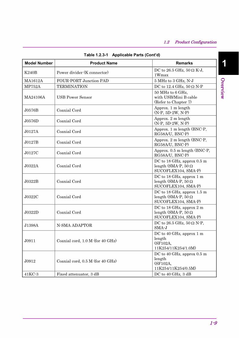
Table 1.2.3-1 Applicable Parts (Cont’d)
Model Number Product Name Remarks
K240B Power divider (K connector) DC to 26.5 GHz, 50 Ω K-J, 1Wmax
MA1612A FOUR-PORT Junction PAD 5 MHz to 3 GHz, N-J MP752A TERMINATION DC to 12.4 GHz, 50 Ω N-P
MA24106A USB Power Sensor 50 MHz to 6 GHz, with USB/Mini B cable (Refer to Chapter 7)
J0576B Coaxial Cord Approx. 1 m length (N-P, 5D-2W, N-P)
J0576D Coaxial Cord Approx. 2 m length (N-P, 5D-2W, N-P)
J0127A Coaxial Cord Approx. 1 m length (BNC-P, RG58A/U, BNC-P)
J0127B Coaxial Cord Approx. 2 m length (BNC-P, RG58A/U, BNC-P)
J0127C Coaxial Cord Approx. 0.5 m length (BNC-P, RG58A/U, BNC-P)
J0322A Coaxial Cord DC to 18 GHz, approx 0.5 m length (SMA-P, 50 Ω SUCOFLEX104, SMA-P)
J0322B Coaxial Cord DC to 18 GHz, approx 1 m length (SMA-P, 50 Ω SUCOFLEX104, SMA-P)
J0322C Coaxial Cord DC to 18 GHz, approx 1.5 m length (SMA-P, 50 Ω SUCOFLEX104, SMA-P)
J0322D Coaxial Cord DC to 18 GHz, approx 2 m length (SMA-P, 50 Ω SUCOFLEX104, SMA-P)
J1398A N-SMA ADAPTOR DC to 26.5 GHz, 50 Ω N-P, SMA-J
J0911 Coaxial cord, 1.0 M (for 40 GHz) DC to 40 GHz, approx 1 m length (SF102A, 11K254/11K254/1.0M)
J0912 Coaxial cord, 0.5 M (for 40 GHz) DC to 40 GHz, approx 0.5 m length (SF102A, 11K254/11K254/0.5M)
41KC-3 Fixed attenuator, 3 dB DC to 40 GHz, 3 dB
Chapter 1 Overview
1-10
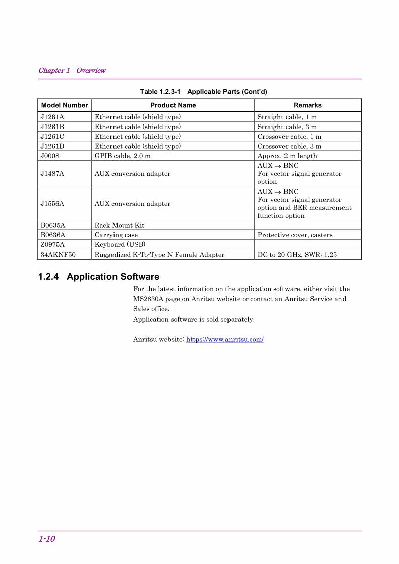
Table 1.2.3-1 Applicable Parts (Cont’d)
Model Number Product Name Remarks J1261A Ethernet cable (shield type) Straight cable, 1 m J1261B Ethernet cable (shield type) Straight cable, 3 m J1261C Ethernet cable (shield type) Crossover cable, 1 m J1261D Ethernet cable (shield type) Crossover cable, 3 m J0008 GPIB cable, 2.0 m Approx. 2 m length
J1487A AUX conversion adapter AUX → BNC For vector signal generator option
J1556A AUX conversion adapter AUX → BNC For vector signal generator option and BER measurement function option
B0635A Rack Mount Kit B0636A Carrying case Protective cover, casters Z0975A Keyboard (USB) 34AKNF50 Ruggedized K-To-Type N Female Adapter DC to 20 GHz, SWR: 1.25
1.2.4 Application Software For the latest information on the application software, either visit the MS2830A page on Anritsu website or contact an Anritsu Service and Sales office. Application software is sold separately. Anritsu website: https://www.anritsu.com/

1.3 Specifications
1-11
1
Overview
1.3 Specifications 1.3.1 Mainframe (MS2830A)
Table 1.3.1-1 through Table 1.3.1-3 show the specifications.
The following specification values are those under the conditions after 30-min warm-up at stable ambient temperature.
Typical values are only for reference and are not guaranteed.
Nominal values are not guaranteed.
The following conditions should apply (unless otherwise noted): Auto Sweep Time Select : Normal Auto Swp Type Rules : Swept Only Switching Speed mode : Normal (Best Phase Noise) Attenuator Mode : Mechanical Atten Only
The specifications of the Signal Analyzer function are values at the center frequency if not specified.
Chapter 1 Overview
1-12
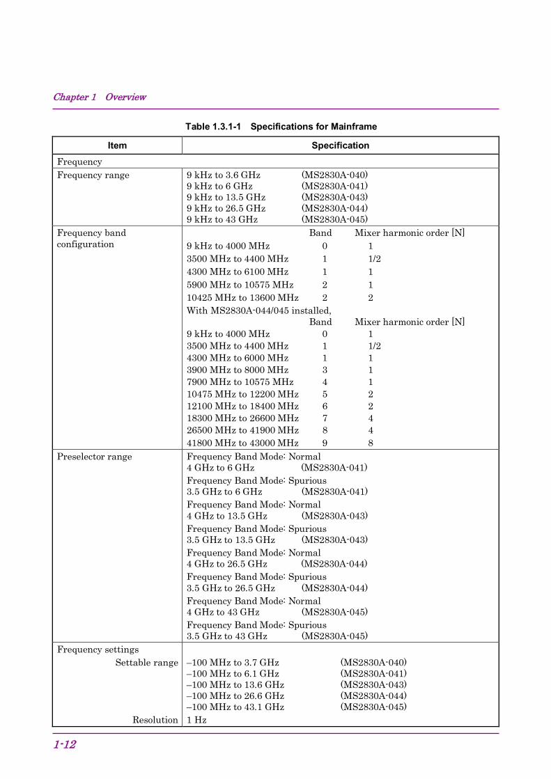
Table 1.3.1-1 Specifications for Mainframe
Item Specification Frequency Frequency range 9 kHz to 3.6 GHz (MS2830A-040)
9 kHz to 6 GHz (MS2830A-041) 9 kHz to 13.5 GHz (MS2830A-043) 9 kHz to 26.5 GHz (MS2830A-044) 9 kHz to 43 GHz (MS2830A-045)
Frequency band configuration
Band Mixer harmonic order [N] 9 kHz to 4000 MHz 0 1 3500 MHz to 4400 MHz 1 1/2 4300 MHz to 6100 MHz 1 1 5900 MHz to 10575 MHz 2 1 10425 MHz to 13600 MHz 2 2 With MS2830A-044/045 installed, Band Mixer harmonic order [N] 9 kHz to 4000 MHz 0 1 3500 MHz to 4400 MHz 1 1/2 4300 MHz to 6000 MHz 1 1 3900 MHz to 8000 MHz 3 1 7900 MHz to 10575 MHz 4 1 10475 MHz to 12200 MHz 5 2 12100 MHz to 18400 MHz 6 2 18300 MHz to 26600 MHz 7 4 26500 MHz to 41900 MHz 8 4 41800 MHz to 43000 MHz 9 8
Preselector range Frequency Band Mode: Normal 4 GHz to 6 GHz (MS2830A-041) Frequency Band Mode: Spurious 3.5 GHz to 6 GHz (MS2830A-041) Frequency Band Mode: Normal 4 GHz to 13.5 GHz (MS2830A-043) Frequency Band Mode: Spurious 3.5 GHz to 13.5 GHz (MS2830A-043) Frequency Band Mode: Normal 4 GHz to 26.5 GHz (MS2830A-044) Frequency Band Mode: Spurious 3.5 GHz to 26.5 GHz (MS2830A-044) Frequency Band Mode: Normal 4 GHz to 43 GHz (MS2830A-045) Frequency Band Mode: Spurious 3.5 GHz to 43 GHz (MS2830A-045)
Frequency settings Settable range
Resolution
–100 MHz to 3.7 GHz (MS2830A-040) –100 MHz to 6.1 GHz (MS2830A-041) –100 MHz to 13.6 GHz (MS2830A-043) –100 MHz to 26.6 GHz (MS2830A-044) –100 MHz to 43.1 GHz (MS2830A-045) 1 Hz
1.3 Specifications
1-13
1
Overview
Table 1.3.1-1 Specifications for Mainframe (Cont’d)
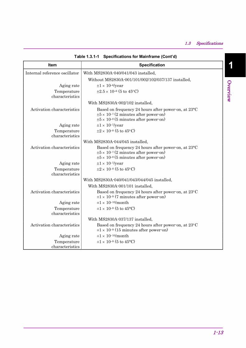
Item Specification
Internal reference oscillator With MS2830A-040/041/043 installed, Without MS2830A-001/101/002/102/037/137 installed,
Aging rate ±1 × 10⁻⁶/year Temperature
characteristics ±2.5 × 10⁻⁶ (5 to 45°C)
With MS2830A-002/102 installed, Activation characteristics
Based on frequency 24 hours after power-on, at 23°C ±5 × 10⁻⁷ (2 minutes after power-on) ±5 × 10⁻⁸ (5 minutes after power-on)
Aging rate ±1 × 10⁻⁷/year Temperature
characteristics ±2 × 10⁻⁸ (5 to 45°C)
With MS2830A-044/045 installed, Activation characteristics
Based on frequency 24 hours after power-on, at 23°C ±5 × 10⁻⁷ (2 minutes after power-on) ±5 × 10⁻⁸ (5 minutes after power-on)
Aging rate ±1 × 10⁻⁷/year Temperature
characteristics ±2 × 10⁻⁸ (5 to 45°C)
With MS2830A-040/041/043/044/045 installed, With MS2830A-001/101 installed,
Activation characteristics
Based on frequency 24 hours after power-on, at 23°C ±1 × 10⁻⁹ (7 minutes after power-on)
Aging rate ±1 × 10⁻¹⁰/month Temperature
characteristics ±1 × 10⁻⁹ (5 to 45°C)
With MS2830A-037/137 installed, Activation characteristics
Based on frequency 24 hours after power-on, at 23°C ±1 × 10⁻⁹ (15 minutes after power-on)
Aging rate ±1 × 10⁻¹⁰/month Temperature
characteristics ±1 × 10⁻⁹ (5 to 45°C)

Chapter 1 Overview
1-14
Table 1.3.1-1 Specifications for Mainframe (Cont’d)
Item Specification Single side band noise At 18 to 28°C, 500 MHz, spectrum analyzer function
Switching Speed mode: Normal (Best Phase Noise) (Frequency offset)
100 kHz 1 MHz
–115 dBc/Hz –133 dBc/Hz
With MS2830A-062 installed and operating (062: Enabled, Center frequency: 500 MHz, and SPAN ≤ 1 MHz as spectrum analyzer) at the temperature of 18 to 28°C.
(Frequency Offset) 1 kHz
10 kHz 100 kHz 1 MHz
–107 dBc/Hz –113 dBc/Hz –133 dBc/Hz –148 dBc/Hz Nominal
With MS2830A-066 installed and operating (066: Enabled, Center frequency: 500 MHz, and SPAN ≤ 1 MHz as spectrum analyzer) at the temperature of 18 to 28°C.
(Frequency Offset) 1 kHz
10 kHz 100 kHz 1 MHz
–109 dBc/Hz –118 dBc/Hz –133 dBc/Hz –148 dBc/Hz Nominal
With MS2830A-066 installed and operating (066: Enabled, Center frequency: 220 MHz, and SPAN ≤ 500 kHz as spectrum analyzer) at the temperature of 18 to 28°C.
(Frequency Offset) 25 kHz
–122 dBc/Hz

1.3 Specifications
1-15
1
Overview
Table 1.3.1-1 Specifications for Mainframe (Cont’d)
Item Specification Amplitude Measurement range Without MS2830A-008/108/068/168 or with Preamplifier turned off
Average noise level up to +30 dBm With MS2830A-008/108/068/168 and Preamplifier turned on
Average noise level up to +10 dBm Maximum input level
Continuous wave
average power DC
Continuous wave
average power DC
Continuous wave average power
DC
Continuous wave average power
DC
With MS2830A-040/041/043 installed, Without MS2830A-008/108 or with Preamplifier turned off:
+30 dBm (Input attenuator ≥ 10 dB) +20 dBm (Input attenuator = 0 dB) ±10 Vdc
With MS2830A-008/108 and Preamplifier turned on: +10 dBm (Input attenuator = 0 dB) ±10 Vdc
With MS2830A-044/045 installed, Without MS2830A-008/108/068/168 or with Preamplifier turned off:
+30 dBm (Input attenuator ≥ 10 dB) +20 dBm (Input attenuator = 0 dB) ±0 Vdc
With MS2830A-008/108/068/168 and Preamplifier turned on: +10 dBm (Input attenuator = 0 dB) ±0 Vdc
Input attenuator With MS2830A-040/041/043/044 installed, 0 to 60 dB, 2 dB steps
With MS2830A-045 installed, Attenuator Mode: E-ATT Combined Mode, Frequency Band Mode: Normal, and Stop frequency ≤ 6 GHz. or Attenuator Mode: E-ATT Combined Mode, Frequency Band Mode: Spurious, and Stop frequency ≤ 4 GHz. 0 to 10 dB, 10 dB steps 10 to 40 dB, 2 dB steps 40 to 60 dB, 10 dB steps Attenuator Mode: M-ATT Only. or Attenuator Mode: E-ATT Combined Mode, Frequency Band Mode: Normal, and Stop frequency > 6 GHz. or Attenuator Mode: E-ATT Combined Mode, Frequency Band Mode: Spurious, and Stop frequency > 4 GHz. 0 to 60 dB, 10 dB steps
Chapter 1 Overview
1-16
Table 1.3.1-1 Specifications for Mainframe (Cont’d)
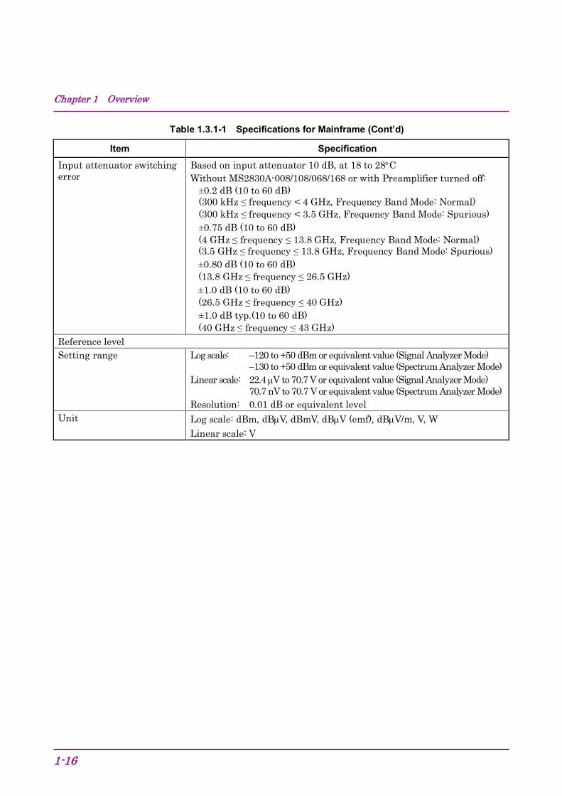
Item Specification Input attenuator switching error
Based on input attenuator 10 dB, at 18 to 28°C Without MS2830A-008/108/068/168 or with Preamplifier turned off:
±0.2 dB (10 to 60 dB) (300 kHz ≤ frequency < 4 GHz, Frequency Band Mode: Normal) (300 kHz ≤ frequency < 3.5 GHz, Frequency Band Mode: Spurious) ±0.75 dB (10 to 60 dB) (4 GHz ≤ frequency ≤ 13.8 GHz, Frequency Band Mode: Normal) (3.5 GHz ≤ frequency ≤ 13.8 GHz, Frequency Band Mode: Spurious) ±0.80 dB (10 to 60 dB) (13.8 GHz ≤ frequency ≤ 26.5 GHz) ±1.0 dB (10 to 60 dB) (26.5 GHz ≤ frequency ≤ 40 GHz) ±1.0 dB typ.(10 to 60 dB) (40 GHz ≤ frequency ≤ 43 GHz)
Reference level Setting range Log scale: –120 to +50 dBm or equivalent value (Signal Analyzer Mode)
−130 to +50 dBm or equivalent value (Spectrum Analyzer Mode) Linear scale: 22.4 µV to 70.7 V or equivalent value (Signal Analyzer Mode)
70.7 nV to 70.7 V or equivalent value (Spectrum Analyzer Mode) Resolution: 0.01 dB or equivalent level
Unit Log scale: dBm, dBµV, dBmV, dBµV (emf), dBµV/m, V, W Linear scale: V
1.3 Specifications
1-17
1
Overview
Table 1.3.1-1 Specifications for Mainframe (Cont’d)
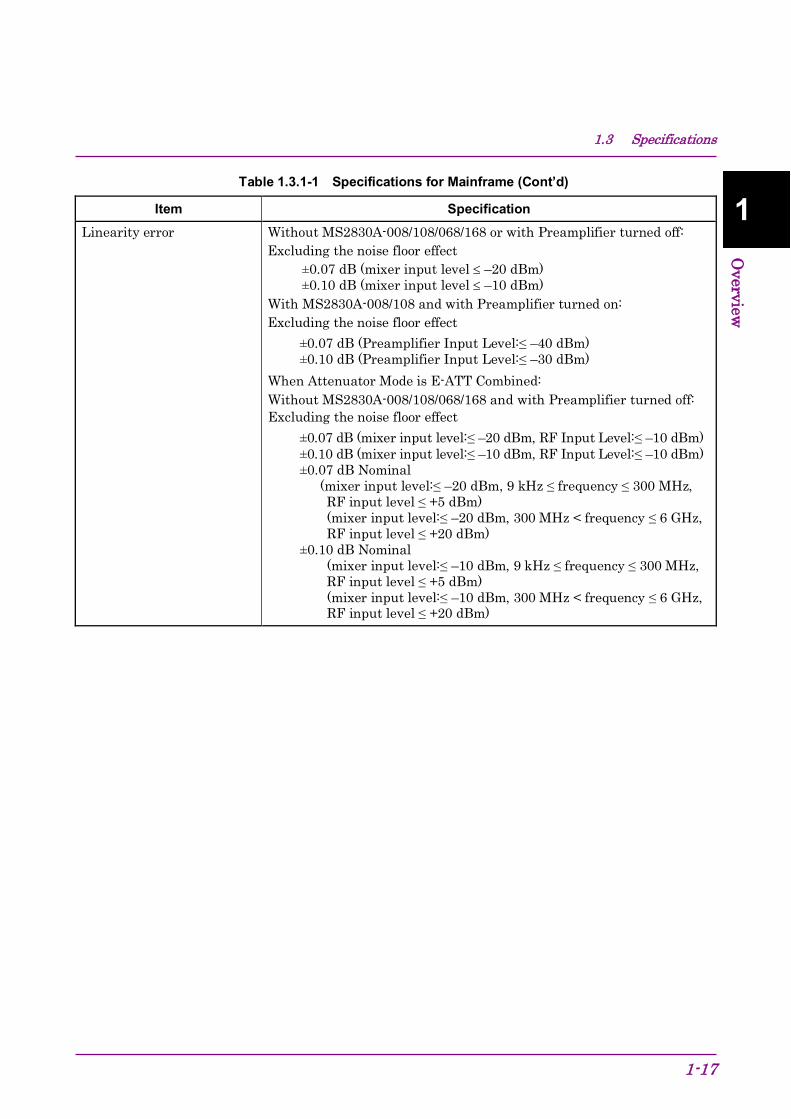
Item Specification Linearity error Without MS2830A-008/108/068/168 or with Preamplifier turned off:
Excluding the noise floor effect ±0.07 dB (mixer input level ≤ –20 dBm) ±0.10 dB (mixer input level ≤ –10 dBm)
With MS2830A-008/108 and with Preamplifier turned on: Excluding the noise floor effect
±0.07 dB (Preamplifier Input Level:≤ –40 dBm) ±0.10 dB (Preamplifier Input Level:≤ –30 dBm)
When Attenuator Mode is E-ATT Combined: Without MS2830A-008/108/068/168 and with Preamplifier turned off: Excluding the noise floor effect
±0.07 dB (mixer input level:≤ –20 dBm, RF Input Level:≤ –10 dBm) ±0.10 dB (mixer input level:≤ –10 dBm, RF Input Level:≤ –10 dBm) ±0.07 dB Nominal (mixer input level:≤ –20 dBm, 9 kHz ≤ frequency ≤ 300 MHz, RF input level ≤ +5 dBm) (mixer input level:≤ –20 dBm, 300 MHz < frequency ≤ 6 GHz, RF input level ≤ +20 dBm) ±0.10 dB Nominal (mixer input level:≤ –10 dBm, 9 kHz ≤ frequency ≤ 300 MHz, RF input level ≤ +5 dBm) (mixer input level:≤ –10 dBm, 300 MHz < frequency ≤ 6 GHz, RF input level ≤ +20 dBm)

Chapter 1 Overview
1-18
Table 1.3.1-1 Specifications for Mainframe (Cont’d)
Item Specification RF frequency characteristics
After CAL execution at 18 to 28°C, input attenuator = 10 dB, With MS2830A-040/041/043, and without MS2830A-008/108, or with Preamplifier turned off:
±1.0 dB (9 kHz ≤ frequency < 300 kHz) ±0.35 dB (300 kHz ≤ frequency < 4 GHz, Frequency Band Mode: Normal) (300 kHz ≤ frequency < 3.5 GHz, Frequency Band Mode: Spurious) ±1.50 dB (4 GHz ≤ frequency ≤ 6 GHz, Frequency Band Mode: Normal) (3.5 GHz ≤ frequency ≤ 6 GHz, Frequency Band Mode: Spurious) ±1.50 dB (6 GHz < frequency)
With MS2830A-040/041/043, and with MS2830A-008/108, and with Preamplifier turned on:
±0.65 dB (300 kHz ≤ frequency < 4 GHz, Frequency Band Mode: Normal) (300 kHz ≤ frequency < 3.5 GHz, Frequency Band Mode: Spurious) ±1.8 dB (4 GHz ≤ frequency ≤ 6 GHz, Frequency Band Mode: Normal) (3.5 GHz ≤ frequency ≤ 6 GHz, Frequency Band Mode: Spurious)
With MS2830A-044/045, Without MS2830A-008/108/068/168, or with Preamplifier turned off, Without MS2830A-067/167 or with Microwave Preselector Bypass turned off and after Preselector Auto Tune is done:
±1.0 dB (9 kHz ≤ frequency < 300 kHz) ±0.35 dB (300 kHz ≤ frequency < 4 GHz, Frequency Band Mode: Normal) (300 kHz ≤ frequency < 3.5 GHz, Frequency Band Mode: Spurious) ±1.50 dB (4 GHz ≤ frequency ≤ 6 GHz, Frequency Band Mode: Normal) (3.5 GHz ≤ frequency ≤ 6 GHz, Frequency Band Mode: Spurious) ±1.50 dB (6 GHz < frequency ≤ 13.8 GHz) ±2.50 dB (13.8 GHz < frequency ≤ 26.5 GHz) ±2.50 dB (26.5 GHz < frequency ≤ 40 GHz) ±2.50 dB typ. (40 GHz < frequency ≤ 43 GHz)
1.3 Specifications
1-19
1
Overview
Table 1.3.1-1 Specifications for Mainframe (Cont’d)
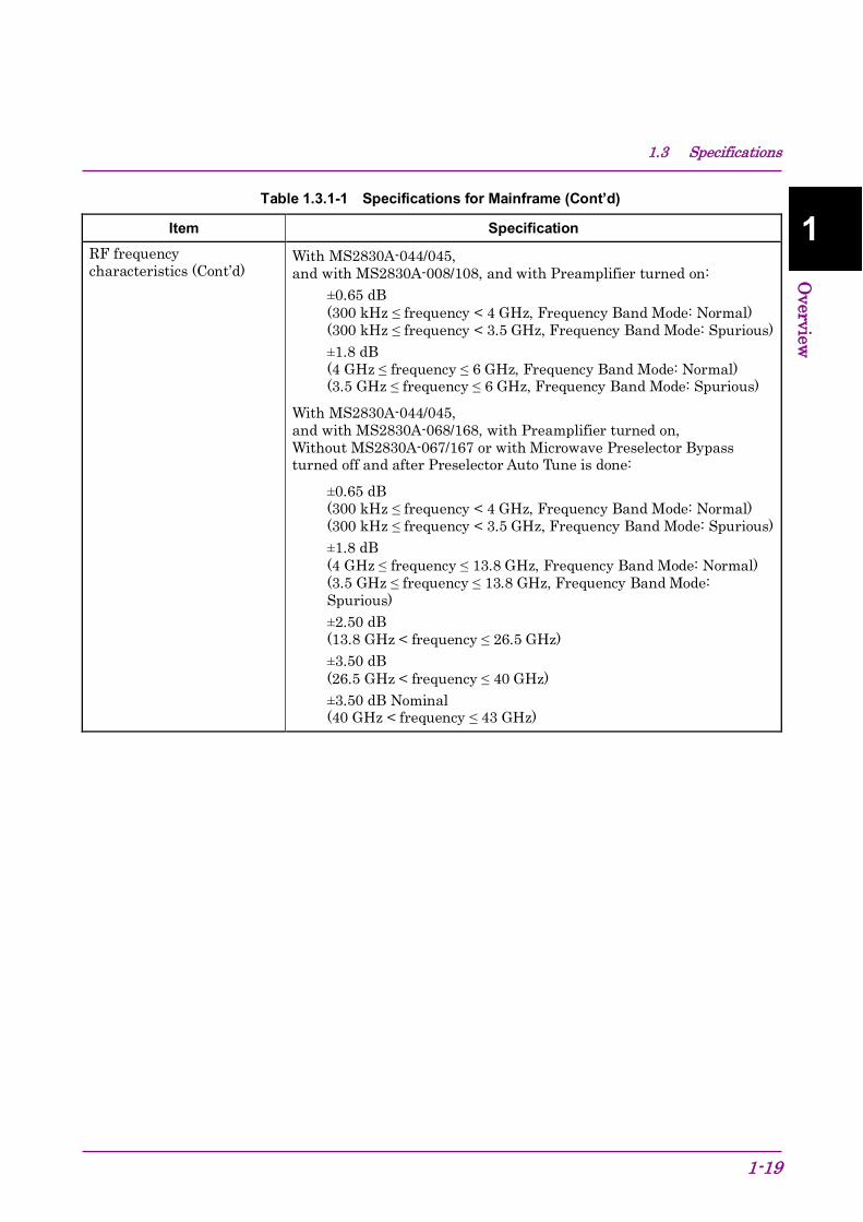
Item Specification RF frequency characteristics (Cont’d)
With MS2830A-044/045, and with MS2830A-008/108, and with Preamplifier turned on:
±0.65 dB (300 kHz ≤ frequency < 4 GHz, Frequency Band Mode: Normal) (300 kHz ≤ frequency < 3.5 GHz, Frequency Band Mode: Spurious) ±1.8 dB (4 GHz ≤ frequency ≤ 6 GHz, Frequency Band Mode: Normal) (3.5 GHz ≤ frequency ≤ 6 GHz, Frequency Band Mode: Spurious)
With MS2830A-044/045, and with MS2830A-068/168, with Preamplifier turned on, Without MS2830A-067/167 or with Microwave Preselector Bypass turned off and after Preselector Auto Tune is done:
±0.65 dB (300 kHz ≤ frequency < 4 GHz, Frequency Band Mode: Normal) (300 kHz ≤ frequency < 3.5 GHz, Frequency Band Mode: Spurious) ±1.8 dB (4 GHz ≤ frequency ≤ 13.8 GHz, Frequency Band Mode: Normal) (3.5 GHz ≤ frequency ≤ 13.8 GHz, Frequency Band Mode: Spurious) ±2.50 dB (13.8 GHz < frequency ≤ 26.5 GHz) ±3.50 dB (26.5 GHz < frequency ≤ 40 GHz) ±3.50 dB Nominal (40 GHz < frequency ≤ 43 GHz)
Chapter 1 Overview
1-20
Table 1.3.1-1 Specifications for Mainframe (Cont’d)
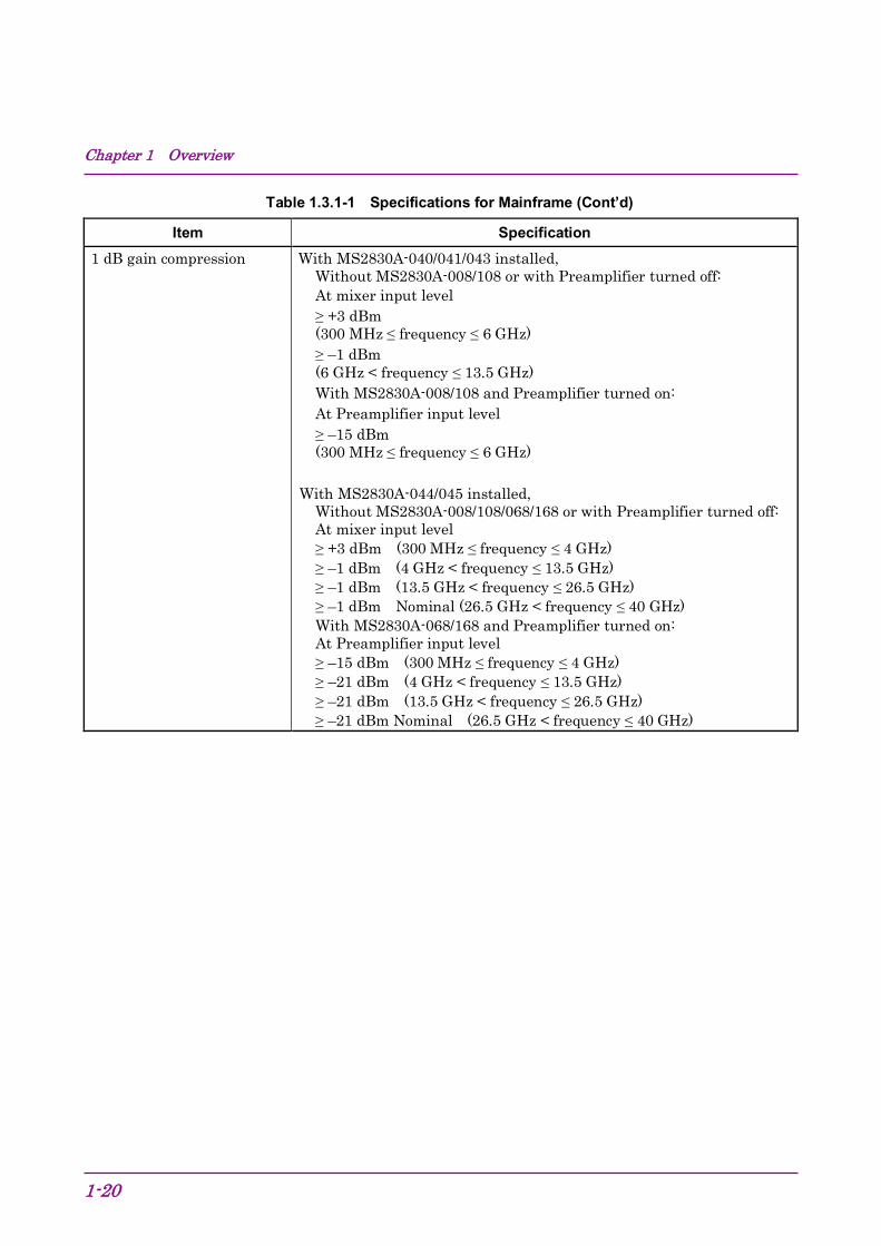
Item Specification 1 dB gain compression With MS2830A-040/041/043 installed,
Without MS2830A-008/108 or with Preamplifier turned off: At mixer input level ≥ +3 dBm (300 MHz ≤ frequency ≤ 6 GHz) ≥ –1 dBm (6 GHz < frequency ≤ 13.5 GHz) With MS2830A-008/108 and Preamplifier turned on: At Preamplifier input level ≥ –15 dBm (300 MHz ≤ frequency ≤ 6 GHz)
With MS2830A-044/045 installed,
Without MS2830A-008/108/068/168 or with Preamplifier turned off: At mixer input level ≥ +3 dBm (300 MHz ≤ frequency ≤ 4 GHz) ≥ –1 dBm (4 GHz < frequency ≤ 13.5 GHz) ≥ –1 dBm (13.5 GHz < frequency ≤ 26.5 GHz) ≥ –1 dBm Nominal (26.5 GHz < frequency ≤ 40 GHz) With MS2830A-068/168 and Preamplifier turned on: At Preamplifier input level ≥ –15 dBm (300 MHz ≤ frequency ≤ 4 GHz) ≥ –21 dBm (4 GHz < frequency ≤ 13.5 GHz) ≥ –21 dBm (13.5 GHz < frequency ≤ 26.5 GHz) ≥ –21 dBm Nominal (26.5 GHz < frequency ≤ 40 GHz)

1.3 Specifications
1-21
1
Overview
Table 1.3.1-1 Specifications for Mainframe (Cont’d)
Item Specification Spurious response Second harmonic wave distortion
With MS2830A-040/041/043 installed, Without MS2830A-008/108 or with Preamplifier turned off: At mixer input level = –30 dBm Harmonics [dBc] SHI [dBm] ≤ –60 ≥ +30 (10 MHz ≤ Input frequency ≤ 300 MHz) ≤ –65 ≥ +35 (300 MHz < Input frequency ≤ 1 GHz) ≤ –65 ≥ +35 (1 GHz < Input frequency ≤ 2 GHz) At mixer input level = –10 dBm Harmonics [dBc] SHI [dBm] ≤ –70 ≥ +60 (2 GHz < Input frequency ≤ 3 GHz, Frequency Band Mode: Normal) ≤ –70 ≥ +60 (1.75 GHz ≤ Input frequency≤ 3 GHz, Frequency Band Mode: Spurious) At mixer input level = –10 dBm Harmonics [dBc] SHI [dBm] ≤ –70 ≥ +60 (3 GHz < Input frequency ≤ 6.75 GHz) With MS2830A-008/108 and with Preamplifier turned on: At preamplifier input level = –45 dBm Harmonics [dBc] SHI [dBm] ≤ –50 ≥ +5 (10 MHz ≤ frequency ≤ 300 MHz) ≤ –55 ≥ +10 (300 MHz ≤ frequency ≤ 3 GHz)
With MS2830A-044/045 installed, Without MS2830A-008/108/068/168 and MS2830A-067/167: At mixer input level = –30 dBm Harmonics [dBc] SHI [dBm] ≤ –60 ≥ +30 (10 MHz ≤ Input frequency ≤ 300 MHz) ≤ –65 ≥ +35 (300 MHz < Input frequency ≤ 1 GHz) ≤ –65 ≥ +35 (1 GHz < Input frequency ≤ 2 GHz, Frequency Band Mode: Normal) ≤ –65 ≥ +35 (1 GHz < Input frequency ≤ 1.75 GHz, Frequency Band Mode: Spurious)
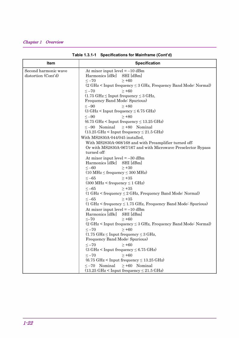
Chapter 1 Overview
1-22
Table 1.3.1-1 Specifications for Mainframe (Cont’d)
Item Specification
Second harmonic wave distortion (Cont’d)
At mixer input level = –10 dBm Harmonics [dBc] SHI [dBm] ≤ –70 ≥ +60 (2 GHz < Input frequency ≤ 3 GHz, Frequency Band Mode: Normal) ≤ –70 ≥ +60 (1.75 GHz ≤ Input frequency ≤ 3 GHz, Frequency Band Mode: Spurious) ≤ –90 ≥ +80 (3 GHz < Input frequency ≤ 6.75 GHz) ≤ –90 ≥ +80 (6.75 GHz < Input frequency ≤ 13.25 GHz) ≤ –90 Nominal ≥ +80 Nominal (13.25 GHz < Input frequency ≤ 21.5 GHz)
With MS2830A-044/045 installed, With MS2830A-068/168 and with Preamplifier turned off: Or with MS2830A-067/167 and with Microwave Preselector Bypass turned off: At mixer input level = –30 dBm Harmonics [dBc] SHI [dBm] ≤ –60 ≥ +30 (10 MHz ≤ frequency ≤ 300 MHz) ≤ –65 ≥ +35 (300 MHz < frequency ≤ 1 GHz) ≤ –65 ≥ +35 (1 GHz < frequency ≤ 2 GHz, Frequency Band Mode: Normal) ≤ –65 ≥ +35 (1 GHz < frequency ≤ 1.75 GHz, Frequency Band Mode: Spurious) At mixer input level = –10 dBm Harmonics [dBc] SHI [dBm] ≤–70 ≥ +60 (2 GHz < Input frequency ≤ 3 GHz, Frequency Band Mode: Normal) ≤ –70 ≥ +60 (1.75 GHz ≤ Input frequency ≤ 3 GHz, Frequency Band Mode: Spurious) ≤ –70 ≥ +60 (3 GHz < Input frequency ≤ 6.75 GHz) ≤ –70 ≥ +60 (6.75 GHz < Input frequency ≤ 13.25 GHz) ≤ –70 Nominal ≥ +60 Nominal (13.25 GHz < Input frequency ≤ 21.5 GHz)
1.3 Specifications
1-23
1
Overview
Table 1.3.1-1 Specifications for Mainframe (Cont’d)
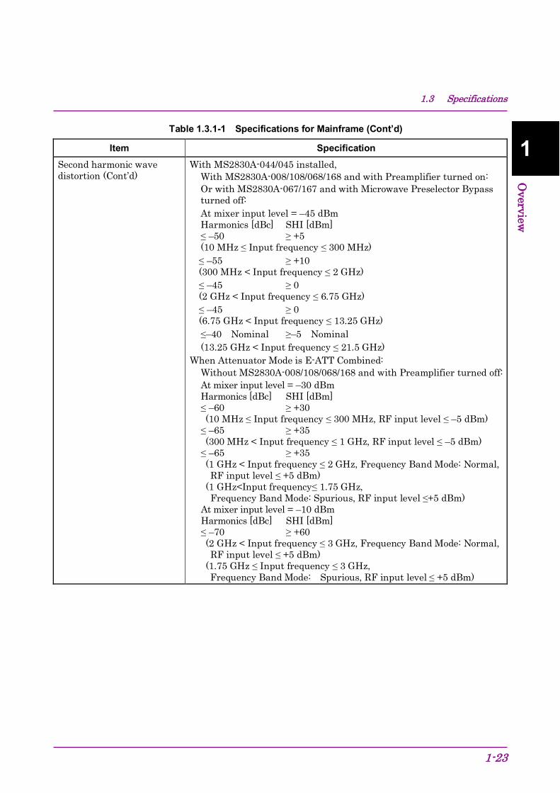
Item Specification Second harmonic wave distortion (Cont’d)
With MS2830A-044/045 installed, With MS2830A-008/108/068/168 and with Preamplifier turned on: Or with MS2830A-067/167 and with Microwave Preselector Bypass turned off: At mixer input level = –45 dBm Harmonics [dBc] SHI [dBm] ≤ –50 ≥ +5 (10 MHz ≤ Input frequency ≤ 300 MHz) ≤ –55 ≥ +10 (300 MHz < Input frequency ≤ 2 GHz) ≤ –45 ≥ 0 (2 GHz < Input frequency ≤ 6.75 GHz) ≤ –45 ≥ 0 (6.75 GHz < Input frequency ≤ 13.25 GHz) ≤–40 Nominal ≥–5 Nominal (13.25 GHz < Input frequency ≤ 21.5 GHz)
When Attenuator Mode is E-ATT Combined: Without MS2830A-008/108/068/168 and with Preamplifier turned off: At mixer input level = –30 dBm Harmonics [dBc] SHI [dBm] ≤ –60 ≥ +30 (10 MHz ≤ Input frequency ≤ 300 MHz, RF input level ≤ –5 dBm) ≤ –65 ≥ +35 (300 MHz < Input frequency ≤ 1 GHz, RF input level ≤ –5 dBm) ≤ –65 ≥ +35 (1 GHz < Input frequency ≤ 2 GHz, Frequency Band Mode: Normal, RF input level ≤ +5 dBm) (1 GHz<Input frequency≤ 1.75 GHz, Frequency Band Mode: Spurious, RF input level ≤+5 dBm) At mixer input level = –10 dBm Harmonics [dBc] SHI [dBm] ≤ –70 ≥ +60 (2 GHz < Input frequency ≤ 3 GHz, Frequency Band Mode: Normal, RF input level ≤ +5 dBm) (1.75 GHz ≤ Input frequency ≤ 3 GHz, Frequency Band Mode: Spurious, RF input level ≤ +5 dBm)

Chapter 1 Overview
1-24
Table 1.3.1-1 Specifications for Mainframe (Cont’d)
Item Specification Second harmonic wave distortion (Cont’d)
At mixer input level = –30 dBm Harmonics [dBc] SHI [dBm] ≤ –60 Nominal ≥ +30 Nominal (10 MHz ≤ Input frequency ≤ 300 MHz, RF input level ≤ 0 dBm) ≤ –65 Nominal ≥ +35 Nominal (300 MHz < Input frequency ≤ 1 GHz, RF input level ≤ +15 dBm) ≤ –65 Nominal ≥ +35 Nominal (1 GHz < Input frequency ≤ 2 GHz, Frequency Band Mode: Normal, RF input level ≤ +15 dBm) (1 GHz < Input frequency ≤ 1.75 GHz, Frequency Band Mode: Spurious, RF input level ≤ +15 dBm) At mixer input level = –10 dBm Harmonics [dBc] SHI [dBm] ≤ –70 Nominal ≥ +60 Nominal (2 GHz ≤ Input frequency ≤ 3 GHz, Frequency Band Mode: Normal, RF input level ≤ +15 dBm) (1.75 GHz ≤ Input frequency ≤ 3 GHz, Frequency Band Mode: Spurious, RF input level ≤ +15 dBm)
SHI: Second Harmonic Intercept Residual response Frequency ≥1 MHz, Input attenuator = 0 dB, at 50 Ω terminator
(With MS2830A-077/177/078/178 installed, excluding Bandwidth > 31.25 MHz.)
Up to 1 GHz ≤ –100 dBm 1 GHz to 6 GHz ≤ –90 dBm typ. 6 GHz to 13.5 GHz ≤ –90 dBm Nominal 13.5 GHz to 26.5 GHz ≤ –90 dBm Nominal. 26.5 GHz to 40 GHz ≤ –80 dBm Nominal.
Connector RF input
Connector With MS2830A-040/041/043/044, Front panel, N-J, 50 Ω VSWR: Input attenuator ≥ 10 dB, 18 to 28ºC ≤ 1.2 (Nominal) (40 MHz ≤ frequency ≤ 3 GHz) ≤ 1.5 (Nominal) (3 GHz < frequency ≤ 6 GHz) ≤ 1.6 (Nominal) (6 GHz < frequency ≤ 13.5 GHz) ≤ 1.9 (Nominal) (13.5 GHz < frequency ≤ 26.5 GHz) With MS2830A-045, Front panel, N-J, 50 Ω VSWR: Input attenuator ≥ 10 dB, 18 to 28ºC ≤ 1.2 (Nominal) (40 MHz ≤ frequency ≤ 3 GHz) ≤ 1.3 (Nominal) (3 GHz < frequency ≤ 6 GHz) ≤ 1.3 (Nominal) (6 GHz < frequency ≤ 13.5 GHz) ≤ 1.4 (Nominal) (13.5 GHz < frequency ≤ 26.5 GHz) ≤ 1.6 (Nominal) (26.5 GHz < frequency ≤ 40 GHz) ≤ 1.6 (Nominal) (40 GHz < frequency ≤ 43 GHz) 40 GHz < frequency ≤ 43 GHz is a value with the V-K converter mounted and included
1.3 Specifications
1-25
1
Overview
Table 1.3.1-1 Specifications for Mainframe (Cont’d)
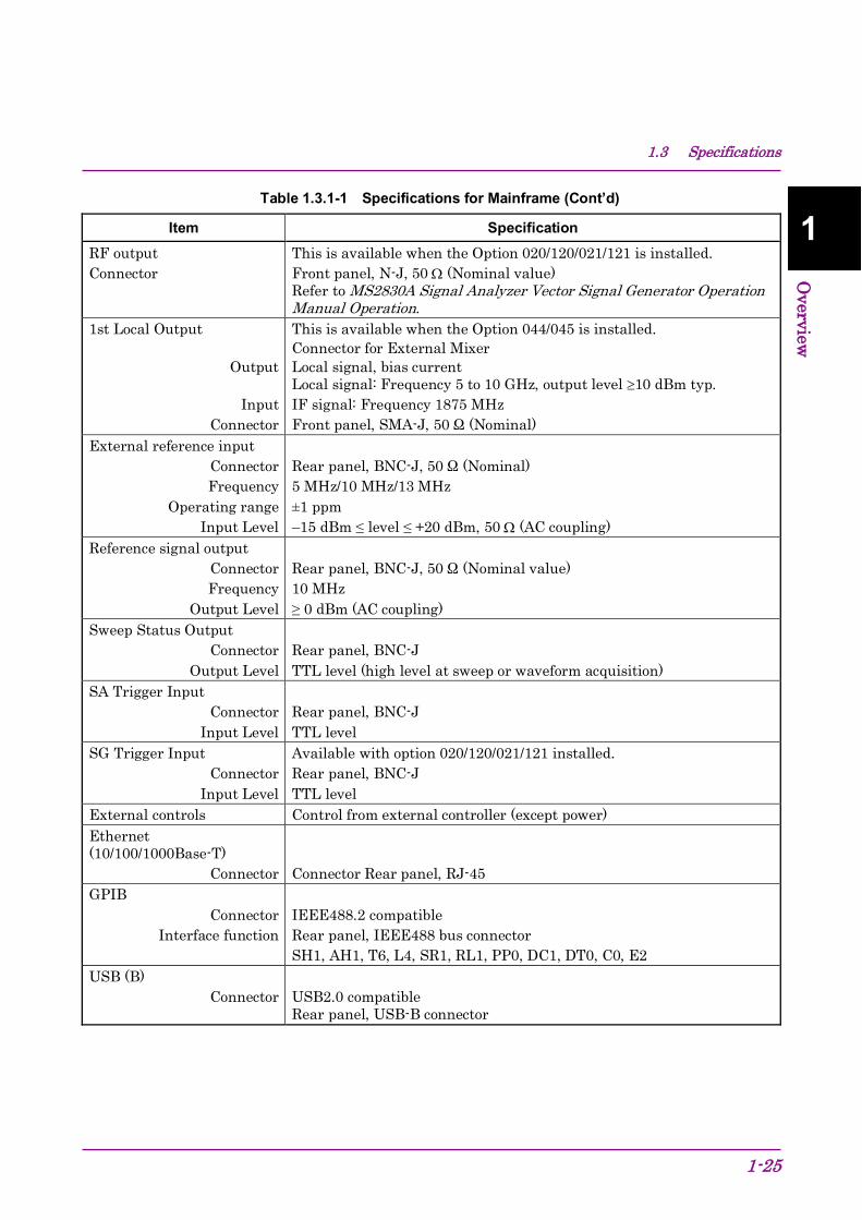
Item Specification RF output Connector
This is available when the Option 020/120/021/121 is installed. Front panel, N-J, 50 Ω (Nominal value) Refer to MS2830A Signal Analyzer Vector Signal Generator Operation Manual Operation.
1st Local Output
Output
Input Connector
This is available when the Option 044/045 is installed. Connector for External Mixer Local signal, bias current Local signal: Frequency 5 to 10 GHz, output level ≥10 dBm typ. IF signal: Frequency 1875 MHz Front panel, SMA-J, 50 Ω (Nominal)
External reference input Connector Frequency
Operating range Input Level
Rear panel, BNC-J, 50 Ω (Nominal) 5 MHz/10 MHz/13 MHz ±1 ppm –15 dBm ≤ level ≤ +20 dBm, 50 Ω (AC coupling)
Reference signal output Connector Frequency
Output Level
Rear panel, BNC-J, 50 Ω (Nominal value) 10 MHz ≥ 0 dBm (AC coupling)
Sweep Status Output Connector
Output Level
Rear panel, BNC-J TTL level (high level at sweep or waveform acquisition)
SA Trigger Input Connector
Input Level
Rear panel, BNC-J TTL level
SG Trigger Input Connector
Input Level
Available with option 020/120/021/121 installed. Rear panel, BNC-J TTL level
External controls Control from external controller (except power) Ethernet (10/100/1000Base-T)
Connector
Connector Rear panel, RJ-45
GPIB Connector
Interface function
IEEE488.2 compatible Rear panel, IEEE488 bus connector SH1, AH1, T6, L4, SR1, RL1, PP0, DC1, DT0, C0, E2
USB (B) Connector
USB2.0 compatible Rear panel, USB-B connector
Chapter 1 Overview
1-26
Table 1.3.1-1 Specifications for Mainframe (Cont’d)
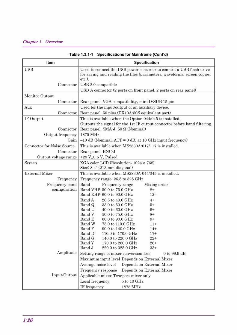
Item Specification USB
Connector
Used to connect the USB power sensor or to connect a USB flash drive for saving and reading the files (parameters, waveforms, screen copies, etc.). USB 2.0 compatible USB-A connector (2 ports on front panel, 2 ports on rear panel)
Monitor Output Connector
Rear panel, VGA compatibility, mini D-SUB 15 pin
Aux Connector
Used for the input/output of an auxiliary device. Rear panel, 50 pins (DX10A-50S equivalent part)
IF Output
Connector Output frequency
Gain
This is available when the Option 044/045 is installed. Outputs the signal for the 1st IF output connector before band filtering. Rear panel, SMA-J, 50 Ω (Nominal) 1875 MHz –10 dB (Nominal, ATT = 0 dB, at 10 GHz input frequency)
Connector for Noise Source Connector
Output voltage range
This is available when MS2830A-017/117 is installed. Rear panel, BNC-J +28 V±0.5 V, Pulsed
Screen XGA color LCD (Resolution: 1024 × 768) Size: 8.4” (213 mm diagonal)
External Mixer Frequency
Frequency band configuration
Amplitude
Input/Output
This is available when MS2830A-044/045 is installed. Frequency range: 26.5 to 325 GHz Band Frequency range Mixing order Band VHP 50.0 to 75.0 GHz 8+ Band EHP 60.0 to 90.0 GHz 12– Band A 26.5 to 40.0 GHz 4+ Band Q 33.0 to 50.0 GHz 5+ Band U 40.0 to 60.0 GHz 6+ Band V 50.0 to 75.0 GHz 8+ Band E 60.0 to 90.0 GHz 9+ Band W 75.0 to 110.0 GHz 11+ Band F 90.0 to 140.0 GHz 14+ Band D 110.0 to 170.0 GHz 17+ Band G 140.0 to 220.0 GHz 22+ Band Y 170.0 to 260.0 GHz 26+ Band J 220.0 to 325.0 GHz 33+ Setting range of mixer conversion loss 0 to 99.9 dB Maximum input level Depends on External Mixer Average noise level Depends on External Mixer Frequency response Depends on External Mixer Applicable mixer: Two-port mixer only Local frequency 5 to 10 GHz IF frequency 1875 MHz
1.3 Specifications
1-27
1
Overview
Table 1.3.1-1 Specifications for Mainframe (Cont’d)
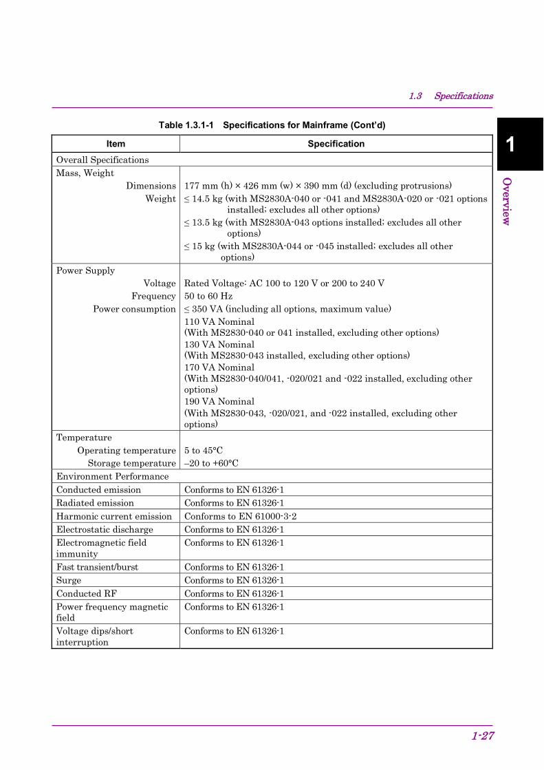
Item Specification Overall Specifications Mass, Weight
Dimensions Weight
177 mm (h) × 426 mm (w) × 390 mm (d) (excluding protrusions) ≤ 14.5 kg (with MS2830A-040 or -041 and MS2830A-020 or -021 options
installed; excludes all other options) ≤ 13.5 kg (with MS2830A-043 options installed; excludes all other
options) ≤ 15 kg (with MS2830A-044 or -045 installed; excludes all other
options) Power Supply
Voltage Frequency
Power consumption
Rated Voltage: AC 100 to 120 V or 200 to 240 V 50 to 60 Hz ≤ 350 VA (including all options, maximum value) 110 VA Nominal (With MS2830-040 or 041 installed, excluding other options) 130 VA Nominal (With MS2830-043 installed, excluding other options) 170 VA Nominal (With MS2830-040/041, -020/021 and -022 installed, excluding other options) 190 VA Nominal (With MS2830-043, -020/021, and -022 installed, excluding other options)
Temperature Operating temperature
Storage temperature
5 to 45°C –20 to +60°C
Environment Performance Conducted emission Conforms to EN 61326-1 Radiated emission Conforms to EN 61326-1 Harmonic current emission Conforms to EN 61000-3-2 Electrostatic discharge Conforms to EN 61326-1 Electromagnetic field immunity
Conforms to EN 61326-1
Fast transient/burst Conforms to EN 61326-1 Surge Conforms to EN 61326-1 Conducted RF Conforms to EN 61326-1 Power frequency magnetic field
Conforms to EN 61326-1
Voltage dips/short interruption
Conforms to EN 61326-1

Chapter 1 Overview
1-28
Table 1.3.1-2 Specifications for Signal Analyzer Function
Item Specification Common Trace mode Spectrum, Power vs Time, Frequency vs Time, CCDF, Spectrogram, No
Trace Bandwidth
Specifies the capture analysis bandwidth from the center frequency 1 kHz to 10 MHz (1-2.5-5 sequence)
(With MS2830A-006/106) 1 kHz to 25 MHz (1-2.5-5 sequence), 31.25 MHz
(With MS2830A-005/105, MS2830A-007 or MS2830A-009/109 installed.) (MS2830A-005/105 is not available when MS2830A-045 is installed.)
1 kHz to 25 MHz (1-2.5-5 sequence), 31.25 MHz, 50 MHz, 62.5 MHz
(With MS2830A-077/177 installed.) 1 kHz to 25 MHz (1-2.5-5 sequence), 31.25 MHz, 50 MHz, 62.5 MHz,
100 MHz, 125 MHz (With MS2830A-078/178 installed.)
Sampling rate
Automatically set depending on analysis bandwidth 2 kHz to 20 MHz (1-2-5 sequence)
(With MS2830A-006/106) 2 kHz to 50 MHz (1-2-5 sequence)
(With MS2830A-005/105, MS2830A-007 or MS2830A-009/109 installed.)
2 kHz to 100 MHz (1-2-5 sequence) (With MS2830A-077/177 installed.)
2 kHz to 200 MHz (1-2-5 sequence) (With MS2830A-078/178 installed.)
1.3 Specifications
1-29
1
Overview
Table 1.3.1-2 Specifications for Signal Analyzer Function (Cont’d)
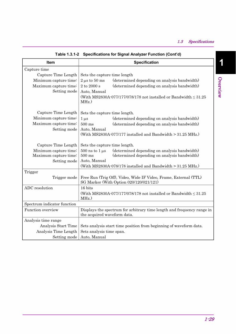
Item Specification Capture time
Capture Time Length Minimum capture time:
Maximum capture time: Setting mode
Capture Time Length Minimum capture time: Maximum capture time:
Setting mode
Capture Time Length Minimum capture time: Maximum capture time:
Setting mode
Sets the capture time length 2 µs to 50 ms (determined depending on analysis bandwidth) 2 to 2000 s (determined depending on analysis bandwidth) Auto, Manual (With MS2830A-077/177/078/178 not installed or Bandwidth ≤ 31.25 MHz.) Sets the capture time length. 1 µs (determined depending on analysis bandwidth) 500 ms (determined depending on analysis bandwidth) Auto, Manual (With MS2830A-077/177 installed and Bandwidth > 31.25 MHz.) Sets the capture time length. 500 ns to 1 µs (determined depending on analysis bandwidth) 500 ms (determined depending on analysis bandwidth) Auto, Manual (With MS2830A-078/178 installed and Bandwidth > 31.25 MHz.)
Trigger Trigger mode
Free Run (Trig Off), Video, Wide IF Video, Frame, External (TTL) SG Marker (With Option 020/120/021/121)
ADC resolution 16 bits (With MS2830A-077/177/078/178 not installed or Bandwidth ≤ 31.25 MHz.)
Spectrum indicator function Function overview Displays the spectrum for arbitrary time length and frequency range in
the acquired waveform data. Analysis time range
Analysis Start Time Analysis Time Length
Setting mode
Sets analysis start time position from beginning of waveform data. Sets analysis time span. Auto, Manual
Chapter 1 Overview
1-30
Table 1.3.1-2 Specifications for Signal Analyzer Function (Cont’d)
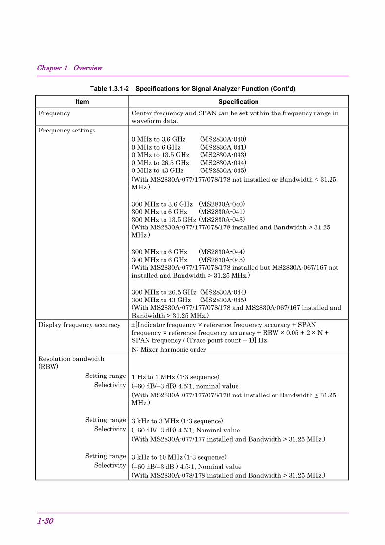
Item Specification Frequency Center frequency and SPAN can be set within the frequency range in
waveform data. Frequency settings
0 MHz to 3.6 GHz (MS2830A-040) 0 MHz to 6 GHz (MS2830A-041) 0 MHz to 13.5 GHz (MS2830A-043) 0 MHz to 26.5 GHz (MS2830A-044) 0 MHz to 43 GHz (MS2830A-045) (With MS2830A-077/177/078/178 not installed or Bandwidth ≤ 31.25 MHz.) 300 MHz to 3.6 GHz (MS2830A-040) 300 MHz to 6 GHz (MS2830A-041) 300 MHz to 13.5 GHz (MS2830A-043) (With MS2830A-077/177/078/178 installed and Bandwidth > 31.25 MHz.) 300 MHz to 6 GHz (MS2830A-044) 300 MHz to 6 GHz (MS2830A-045) (With MS2830A-077/177/078/178 installed but MS2830A-067/167 not installed and Bandwidth > 31.25 MHz.) 300 MHz to 26.5 GHz (MS2830A-044) 300 MHz to 43 GHz (MS2830A-045) (With MS2830A-077/177/078/178 and MS2830A-067/167 installed and Bandwidth > 31.25 MHz.)
Display frequency accuracy ±[Indicator frequency × reference frequency accuracy + SPAN frequency × reference frequency accuracy + RBW × 0.05 + 2 × N + SPAN frequency / (Trace point count – 1)] Hz N: Mixer harmonic order
Resolution bandwidth (RBW)
Setting range Selectivity
Setting range Selectivity
Setting range Selectivity
1 Hz to 1 MHz (1-3 sequence) (–60 dB/–3 dB) 4.5:1, nominal value (With MS2830A-077/177/078/178 not installed or Bandwidth ≤ 31.25 MHz.) 3 kHz to 3 MHz (1-3 sequence) (–60 dB/–3 dB) 4.5:1, Nominal value (With MS2830A-077/177 installed and Bandwidth > 31.25 MHz.) 3 kHz to 10 MHz (1-3 sequence) (–60 dB/–3 dB ) 4.5:1, Nominal value (With MS2830A-078/178 installed and Bandwidth > 31.25 MHz.)
1.3 Specifications
1-31
1
Overview
Table 1.3.1-2 Specifications for Signal Analyzer Function (Cont’d)
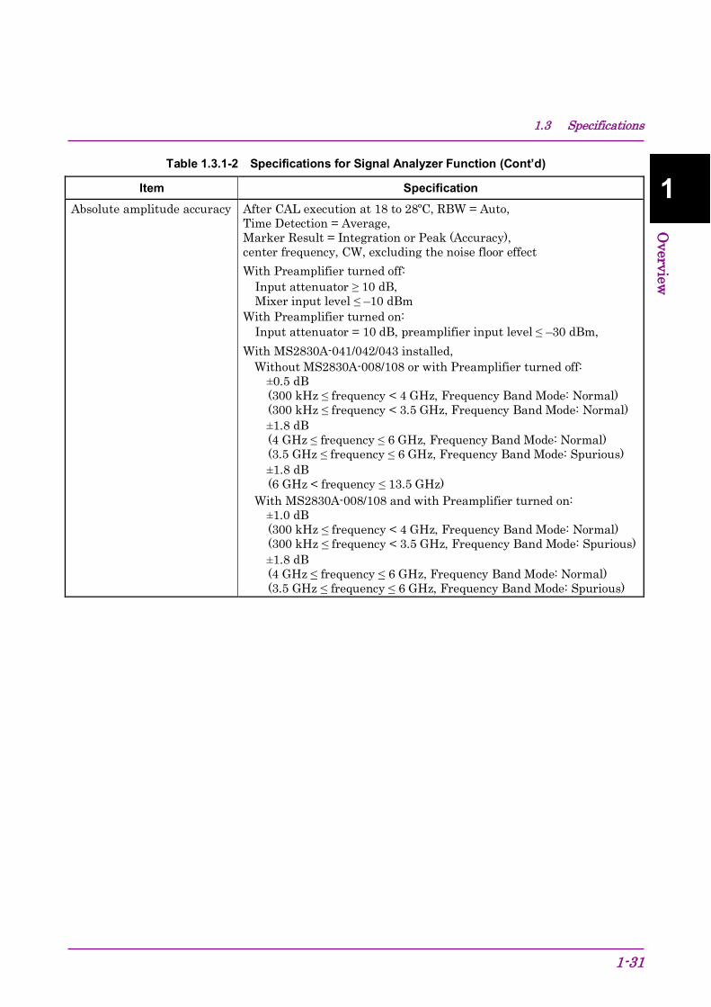
Item Specification Absolute amplitude accuracy After CAL execution at 18 to 28ºC, RBW = Auto,
Time Detection = Average, Marker Result = Integration or Peak (Accuracy), center frequency, CW, excluding the noise floor effect With Preamplifier turned off: Input attenuator ≥ 10 dB, Mixer input level ≤ –10 dBm With Preamplifier turned on: Input attenuator = 10 dB, preamplifier input level ≤ –30 dBm, With MS2830A-041/042/043 installed,
Without MS2830A-008/108 or with Preamplifier turned off: ±0.5 dB
(300 kHz ≤ frequency < 4 GHz, Frequency Band Mode: Normal) (300 kHz ≤ frequency < 3.5 GHz, Frequency Band Mode: Normal)
±1.8 dB (4 GHz ≤ frequency ≤ 6 GHz, Frequency Band Mode: Normal) (3.5 GHz ≤ frequency ≤ 6 GHz, Frequency Band Mode: Spurious)
±1.8 dB (6 GHz < frequency ≤ 13.5 GHz)
With MS2830A-008/108 and with Preamplifier turned on: ±1.0 dB
(300 kHz ≤ frequency < 4 GHz, Frequency Band Mode: Normal) (300 kHz ≤ frequency < 3.5 GHz, Frequency Band Mode: Spurious)
±1.8 dB (4 GHz ≤ frequency ≤ 6 GHz, Frequency Band Mode: Normal) (3.5 GHz ≤ frequency ≤ 6 GHz, Frequency Band Mode: Spurious)
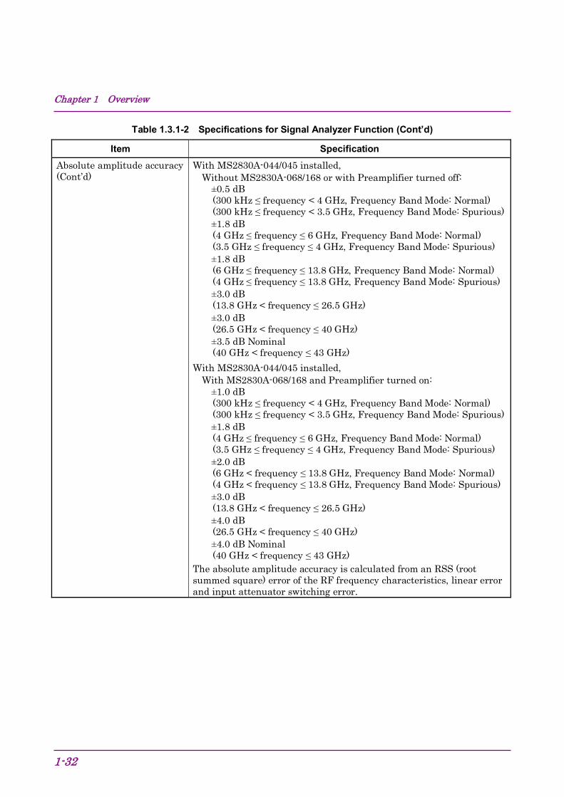
Chapter 1 Overview
1-32
Table 1.3.1-2 Specifications for Signal Analyzer Function (Cont’d)
Item Specification Absolute amplitude accuracy (Cont’d)
With MS2830A-044/045 installed, Without MS2830A-068/168 or with Preamplifier turned off: ±0.5 dB
(300 kHz ≤ frequency < 4 GHz, Frequency Band Mode: Normal) (300 kHz ≤ frequency < 3.5 GHz, Frequency Band Mode: Spurious)
±1.8 dB (4 GHz ≤ frequency ≤ 6 GHz, Frequency Band Mode: Normal) (3.5 GHz ≤ frequency ≤ 4 GHz, Frequency Band Mode: Spurious)
±1.8 dB (6 GHz ≤ frequency ≤ 13.8 GHz, Frequency Band Mode: Normal) (4 GHz ≤ frequency ≤ 13.8 GHz, Frequency Band Mode: Spurious)
±3.0 dB (13.8 GHz < frequency ≤ 26.5 GHz)
±3.0 dB (26.5 GHz < frequency ≤ 40 GHz)
±3.5 dB Nominal (40 GHz < frequency ≤ 43 GHz)
With MS2830A-044/045 installed, With MS2830A-068/168 and Preamplifier turned on: ±1.0 dB
(300 kHz ≤ frequency < 4 GHz, Frequency Band Mode: Normal) (300 kHz ≤ frequency < 3.5 GHz, Frequency Band Mode: Spurious)
±1.8 dB (4 GHz ≤ frequency ≤ 6 GHz, Frequency Band Mode: Normal) (3.5 GHz ≤ frequency ≤ 4 GHz, Frequency Band Mode: Spurious)
±2.0 dB (6 GHz < frequency ≤ 13.8 GHz, Frequency Band Mode: Normal) (4 GHz < frequency ≤ 13.8 GHz, Frequency Band Mode: Spurious)
±3.0 dB (13.8 GHz < frequency ≤ 26.5 GHz)
±4.0 dB (26.5 GHz < frequency ≤ 40 GHz)
±4.0 dB Nominal (40 GHz < frequency ≤ 43 GHz)
The absolute amplitude accuracy is calculated from an RSS (root summed square) error of the RF frequency characteristics, linear error and input attenuator switching error.

1.3 Specifications
1-33
1
Overview
Table 1.3.1-2 Specifications for Signal Analyzer Function (Cont’d)
Item Specification In-band frequency characteristics
With MS2830A-040/041/043 installed, (With MS2830A-077/177/078/178 not installed or Bandwidth ≤ 31.25 MHz.) On the basis of a level of the center frequency, at 18 to 28°C in center frequency ±10 MHz ±0.31 dB
(30 MHz ≤ frequency ≤ 4 GHz, Frequency Band Mode: Normal) (30 MHz ≤ frequency < 3.5 GHz, Frequency Band Mode: Spurious)
With MS2830A-044/045 installed, (With MS2830A-077/177/078/178 not installed or Bandwidth ≤ 31.25 MHz.) On the basis of a level of the center frequency, at 18 to 28°C in center frequency ±10 MHz ±0.31 dB
(30 MHz ≤ frequency ≤ 4 GHz, Frequency Band Mode: Normal) (30 MHz ≤ frequency < 3.5 GHz, Frequency Band Mode: Spurious)

Chapter 1 Overview
1-34
Table 1.3.1-2 Specifications for Signal Analyzer Function (Cont’d)
Item Specification
Display average noise level At 18 to 28ºC, Time Detection = Average, input attenuator = 0 dB, With MS2830A-040/041/043 installed, (With MS2830A-077/177/078/178 not installed or Bandwidth ≤ 31.25 MHz.)
Without MS2830A-062/066, Without MS2830A-008/108 or with Preamplifier turned off:
100 kHz –131.5 [dBm/Hz] 1 MHz –141.5 [dBm/Hz] 30 MHz ≤ frequency < 1 GHz –150.5 [dBm/Hz] 1 GHz ≤ frequency < 2.4 GHz –148.5 [dBm/Hz] 2.4 GHz ≤ frequency ≤ 3.5 GHz –146.5 [dBm/Hz] With MS2830A-041/043 3.5 GHz < frequency ≤ 6 GHz –143.5 [dBm/Hz] With MS2830A-043 6 GHz < frequency ≤ 13.5 GHz –139.5 [dBm/Hz]
Without MS2830A-062/066, With MS2830A-008/108 or with Preamplifier turned on:
100 kHz –144.5 [dBm/Hz] Nominal 1 MHz –153.5 [dBm/Hz] 30 MHz ≤ frequency < 1 GHz –160.5 [dBm/Hz] 1 GHz ≤ frequency < 2 GHz –159.5 [dBm/Hz] 2 GHz ≤ frequency ≤ 3.5 GHz –157.5 [dBm/Hz] With MS2830A-041/043, Frequency Band Mode: Normal 3.5 GHz < frequency ≤ 4 GHz –154.5 [dBm/Hz] With MS2830A-041/043, Frequency Band Mode: Spurious 3.5 GHz < frequency ≤ 4 GHz –154.5 [dBm/Hz] With MS2830A-041/043 4 GHz < frequency ≤ 6 GHz –154.5 [dBm/Hz]
With MS2830A-062/066 installed, Without MS2830A-008/108 or with Preamplifier turned off:
100 kHz –130.5 [dBm/Hz] 1 MHz –140.5 [dBm/Hz] 30 MHz ≤ frequency < 1 GHz –149.5 [dBm/Hz] 1 GHz ≤ frequency < 2.4 GHz –147.5 [dBm/Hz] 2.4 GHz ≤ frequency ≤ 3.5 GHz –144.5 [dBm/Hz] With MS2830A-041/043 installed, 3.5 GHz < frequency ≤ 6 GHz –141.5 [dBm/Hz] With MS2830A-043 installed, 6 GHz < frequency ≤ 13.5 GHz –139.5 [dBm/Hz]

1.3 Specifications
1-35
1
Overview
Table 1.3.1-2 Specifications for Signal Analyzer Function (Cont’d)
Item Specification
Display average noise level (Cont’d)
With MS2830A-062/066 installed, With MS2830A-008/108 and with Preamplifier turned on:
100 kHz –143.5 [dBm/Hz] Nominal 1 MHz –152.5 [dBm/Hz] 30 MHz ≤ frequency < 1 GHz –159.5 [dBm/Hz] 1 GHz ≤ frequency < 2 GHz –158.5 [dBm/Hz] 2 GHz ≤ frequency ≤ 3.5 GHz –155.5 [dBm/Hz] With MS2830A-041/043 installed, Frequency Band Mode: Normal 3.5 GHz < frequency ≤ 4 GHz –151.5 [dBm/Hz] With MS2830A-041/043 installed, Frequency Band Mode: Spurious 3.5 GHz < frequency ≤ 4 GHz –151.5 [dBm/Hz] With MS2830A-041/043 installed, 4 GHz < frequency ≤ 6 GHz –151.5 [dBm/Hz]
With MS2830A-040/041/043 installed, With MS2830A-077/177/078/178, analysis bandwidth > 31.25 MHz
Without MS2830A-062/066, Without MS2830A-008/108, or with Preamplifier turned off:
300 MHz ≤ frequency < 1 GHz –146.5 [dBm/Hz] 1 GHz ≤ frequency < 2.4 GHz –144.5 [dBm/Hz] 2.4 GHz ≤ frequency ≤ 3.5 GHz –142.5 [dBm/Hz] With MS2830A-041/043 installed, 3.5 GHz < frequency ≤ 6 GHz –139.5 [dBm/Hz] With MS2830A-043 installed, 6 GHz < frequency ≤ 13.5 GHz –135.5 [dBm/Hz]
Without MS2830A-062/066, With MS2830A-008/108, and with Preamplifier turned on:
300 MHz ≤ frequency < 1 GHz –156.5 [dBm/Hz] 1 GHz ≤ frequency < 2 GHz –155.5 [dBm/Hz] 2 GHz ≤ frequency ≤ 3.5 GHz –153.5 [dBm/Hz] With MS2830A-043 installed, 3.5 GHz < frequency ≤ 6 GHz –150.5 [dBm/Hz]
With MS2830A-062/066, Without MS2830A-008/108, or with Preamplifier turned off:
300 MHz ≤ frequency < 1 GHz –143.5 [dBm/Hz] 1 GHz ≤ frequency < 2.4 GHz –141.5 [dBm/Hz] 2.4 GHz ≤ frequency ≤ 3.5 GHz –138.5 [dBm/Hz] With MS2830A-041/043 installed, 3.5 GHz < frequency ≤ 6 GHz –135.5 [dBm/Hz] With MS2830A-043 installed, 6 GHz < frequency ≤ 13.5 GHz –135.5 [dBm/Hz]
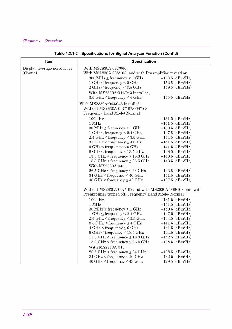
Chapter 1 Overview
1-36
Table 1.3.1-2 Specifications for Signal Analyzer Function (Cont’d)
Item Specification Display average noise level (Cont’d)
With MS2830A-062/066, With MS2830A-008/108, and with Preamplifier turned on
300 MHz ≤ frequency < 1 GHz –153.5 [dBm/Hz] 1 GHz ≤ frequency < 2 GHz –152.5 [dBm/Hz] 2 GHz ≤ frequency ≤ 3.5 GHz –149.5 [dBm/Hz] With MS2830A-041/043 installed, 3.5 GHz ≤ frequency < 6 GHz –145.5 [dBm/Hz]
With MS2830A-044/045 installed, Without MS2830A-067/167/068/168 Frequency Band Mode: Normal
100 kHz –131.5 [dBm/Hz] 1 MHz –141.5 [dBm/Hz] 30 MHz ≤ frequency < 1 GHz –150.5 [dBm/Hz] 1 GHz ≤ frequency < 2.4 GHz –147.5 [dBm/Hz] 2.4 GHz ≤ frequency ≤ 3.5 GHz –144.5 [dBm/Hz] 3.5 GHz < frequency ≤ 4 GHz –141.5 [dBm/Hz] 4 GHz < frequency ≤ 6 GHz –141.5 [dBm/Hz] 6 GHz < frequency ≤ 13.5 GHz –148.5 [dBm/Hz] 13.5 GHz < frequency ≤ 18.3 GHz –146.5 [dBm/Hz] 18.3 GHz < frequency ≤ 26.5 GHz –143.5 [dBm/Hz] With MS2830A-045, 26.5 GHz < frequency ≤ 34 GHz –143.5 [dBm/Hz] 34 GHz < frequency ≤ 40 GHz –141.5 [dBm/Hz] 40 GHz < frequency ≤ 43 GHz –137.5 [dBm/Hz]
Without MS2830A-067/167 and with MS2830A-068/168, and with Preamplifier turned off, Frequency Band Mode: Normal
100 kHz –131.5 [dBm/Hz] 1 MHz –141.5 [dBm/Hz] 30 MHz ≤ frequency < 1 GHz –150.5 [dBm/Hz] 1 GHz ≤ frequency < 2.4 GHz –147.5 [dBm/Hz] 2.4 GHz ≤ frequency ≤ 3.5 GHz –144.5 [dBm/Hz] 3.5 GHz < frequency ≤ 4 GHz –141.5 [dBm/Hz] 4 GHz < frequency ≤ 6 GHz –141.5 [dBm/Hz] 6 GHz < frequency ≤ 13.5 GHz –144.5 [dBm/Hz] 13.5 GHz < frequency ≤ 18.3 GHz –142.5 [dBm/Hz] 18.3 GHz < frequency ≤ 26.5 GHz –138.5 [dBm/Hz] With MS2830A-045, 26.5 GHz < frequency ≤ 34 GHz –138.5 [dBm/Hz] 34 GHz < frequency ≤ 40 GHz –132.5 [dBm/Hz] 40 GHz < frequency ≤ 43 GHz –129.5 [dBm/Hz]
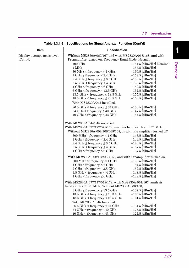
1.3 Specifications
1-37
1
Overview
Table 1.3.1-2 Specifications for Signal Analyzer Function (Cont’d)
Item Specification Display average noise level (Cont’d)
Without MS2830A-067/167 and with MS2830A-068/168, and with Preamplifier turned on, Frequency Band Mode: Normal
100 kHz –144.5 [dBm/Hz] Nominal 1 MHz –153.5 [dBm/Hz] 30 MHz ≤ frequency < 1 GHz –160.5 [dBm/Hz] 1 GHz ≤ frequency < 2.4 GHz –158.5 [dBm/Hz] 2.4 GHz ≤ frequency ≤ 3.5 GHz –156.5 [dBm/Hz] 3.5 GHz < frequency ≤ 4 GHz –152.5 [dBm/Hz] 4 GHz < frequency ≤ 6 GHz –152.5 [dBm/Hz] 6 GHz < frequency ≤ 13.5 GHz –157.5 [dBm/Hz] 13.5 GHz < frequency ≤ 18.3 GHz –155.5 [dBm/Hz] 18.3 GHz < frequency ≤ 26.5 GHz –153.5 [dBm/Hz] With MS2830A-045 installed, 26.5 GHz < frequency ≤ 34 GHz –153.5 [dBm/Hz] 34 GHz < frequency ≤ 40 GHz –147.5 [dBm/Hz] 40 GHz < frequency ≤ 43 GHz –144.5 [dBm/Hz]
With MS2830A-044/045 installed, With MS2830A-077/177/078/178, analysis bandwidth > 31.25 MHz
Without MS2830A-008/108/068/168, or with Preamplifier turned off: 300 MHz ≤ frequency < 1 GHz –146.5 [dBm/Hz] 1 GHz ≤ frequency < 2.4 GHz –143.5 [dBm/Hz] 2.4 GHz ≤ frequency ≤ 3.5 GHz –140.5 [dBm/Hz] 3.5 GHz < frequency ≤ 4 GHz –137.5 [dBm/Hz] 4 GHz < frequency ≤ 6 GHz –137.5 [dBm/Hz]
With MS2830A-008/108/068/168, and with Preamplifier turned on. 300 MHz ≤ frequency < 1 GHz –156.5 [dBm/Hz] 1 GHz ≤ frequency < 2 GHz –154.5 [dBm/Hz] 2 GHz ≤ frequency ≤ 3.5 GHz –152.5 [dBm/Hz] 3.5 GHz < frequency ≤ 4 GHz –148.5 [dBm/Hz] 4 GHz < frequency ≤ 6 GHz –148.5 [dBm/Hz]
With MS2830A-077/177/078/178, with MS2830A-067/167, analysis bandwidth > 31.25 MHz, Without MS2830A-068/168,
6 GHz ≤ frequency ≤ 13.5 GHz –137.5 [dBm/Hz] 13.5 GHz < frequency ≤ 18.3 GHz –135.5 [dBm/Hz] 18.3 GHz < frequency ≤ 26.5 GHz –131.5 [dBm/Hz] With MS2830A-045 Installed 26.5 GHz < frequency ≤ 34 GHz –131.5 [dBm/Hz] 34 GHz < frequency ≤ 40 GHz –125.5 [dBm/Hz] 40 GHz < frequency ≤ 43 GHz –122.5 [dBm/Hz]

Chapter 1 Overview
1-38
Table 1.3.1-2 Specifications for Signal Analyzer Function (Cont’d)
Item Specification Display average noise level (Cont’d)
With MS2830A-068/168, and with Preamplifier turned off. 6 GHz ≤ frequency ≤ 13.5 GHz –132.5 [dBm/Hz] 13.5 GHz < frequency ≤ 18.3 GHz –130.5 [dBm/Hz] 18.3 GHz < frequency ≤ 26.5 GHz –126.5 [dBm/Hz] With MS2830A-045 Installed 26.5 GHz < frequency ≤ 34 GHz –126.5 [dBm/Hz] 34 GHz < frequency ≤ 40 GHz –121.5 [dBm/Hz] 40 GHz < frequency ≤ 43 GHz –118.5 [dBm/Hz]
With MS2830A-068/168, and with Preamplifier turned on. 6 GHz ≤ frequency ≤ 13.5 GHz –147.5 [dBm/Hz] 13.5 GHz < frequency ≤ 18.3 GHz –145.5 [dBm/Hz] 18.3 GHz < frequency ≤ 26.5 GHz –143.5 [dBm/Hz] With MS2830A-045 Installed 26.5 GHz < frequency ≤ 34 GHz –143.5 [dBm/Hz] 34 GHz < frequency ≤ 40 GHz –137.5 [dBm/Hz] 40 GHz < frequency ≤ 43 GHz –134.5 [dBm/Hz]
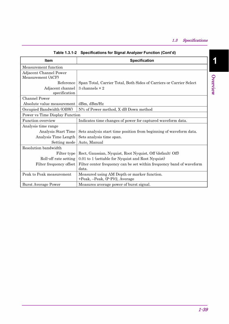
1.3 Specifications
1-39
1
Overview
Table 1.3.1-2 Specifications for Signal Analyzer Function (Cont’d)
Item Specification Measurement function Adjacent Channel Power Measurement (ACP)
Reference Adjacent channel
specification
Span Total, Carrier Total, Both Sides of Carriers or Carrier Select 3 channels × 2
Channel Power Absolute value measurement
dBm, dBm/Hz
Occupied Bandwidth (OBW) N% of Power method, X dB Down method Power vs Time Display Function Function overview Indicates time changes of power for captured waveform data. Analysis time range
Analysis Start Time Analysis Time Length
Setting mode
Sets analysis start time position from beginning of waveform data. Sets analysis time span. Auto, Manual
Resolution bandwidth Filter type
Roll-off rate setting Filter frequency offset
Rect, Gaussian, Nyquist, Root Nyquist, Off (default: Off) 0.01 to 1 (settable for Nyquist and Root Nyquist) Filter center frequency can be set within frequency band of waveform data.
Peak to Peak measurement Measured using AM Depth or marker function. +Peak, –Peak, (P-P)/2, Average
Burst Average Power Measures average power of burst signal.

Chapter 1 Overview
1-40
Table 1.3.1-2 Specifications for Signal Analyzer Function (Cont’d)
Item Specification Frequency vs Time Display Function Function overview Displays frequency time fluctuations of input signal from captured
waveform data. Analysis time range
Analysis Start Time Analysis Time Length
Setting mode
Sets analysis start time position from beginning of waveform data. Sets analysis time span. Auto, Manual
Operating level range –17 to +30 dBm (Input attenuator ≥ 10 dB) Frequency (vertical axis)
Display frequency range Input frequency range
Center frequency and SPAN can be set within the frequency range in waveform data Selectable from 1/25, 1/10, 1/5 and 1/2 of analysis bandwidth 10 MHz to 6 GHz
Display frequency accuracy
Input level = –17 to +30 dBm, SPAN ≤ 31.25 MHz, scale = SPAN/25: At CW input ±(reference oscillator accuracy × center frequency + indicator frequency range×0.01) Hz
Peak to Peak measurement Measured using FM Depth or marker function. +Peak, –Peak, (P-P)/2, Average
FM CW measurement Measures the following items after detecting chirp signals automatically or specifying the range by marker. FM Error Peak, FM Error RMS, Chirp Deviation, Chirp Rate, Chirp Length
CCDF Display Function Function overview Displays CCDF and APD of waveform data captured at specific time. Analysis time range
Analysis Start Time Analysis Time Length
Setting mode
Sets analysis start time position from beginning of waveform data. Sets analysis time span. Auto, Manual
Display
Histogram resolution Numerical value
Graphically displays CCDF and APD. 0.01 dB Average Power, Max Power, Crest Factor
Resolution Bandwidth Filter type
Filter frequency offset
Rectangle, Off (default: Off) Filter center frequency can be set within frequency band of waveform data.

1.3 Specifications
1-41
1
Overview
Table 1.3.1-2 Specifications for Signal Analyzer Function (Cont’d)
Item Specification Spectrogram Display Function Function overview Displays the spectrum for selected time length in the acquired
waveform data. Analysis time range
Analysis Start Time Analysis Time Length
Setting mode
Sets analysis start time position from beginning of waveform data. Sets analysis time span. Auto, Manual
Frequency
Center frequency and SPAN can be set within the frequency range in waveform data.
Resolution bandwidth (RBW)
Setting range Selectivity
1 Hz to 1 MHz (1-3 sequence) (–60 dB/–3 dB ) 4.5:1, Nominal value
Digitize function Function overview Capable of outputting captured waveform data to internal hard disk or
external device Waveform data
Format Level
Level accuracy
I, Q (32-bit Float Binary format) √(I2 + Q2) = 1 at 0 dBm input Same as absolute amplitude accuracy of signal analyzer
External output Capable of outputting to external PC through Ethernet

Chapter 1 Overview
1-42
Table 1.3.1-2 Specifications for Signal Analyzer Function (Cont’d)
Item Specification Replay Function Function overview Analyzes traces of saved waveform data Conditions for measurable waveform data
I, Q (Binary format)
Conditions for measurable waveform data
SPAN Sampling rate 1 kHz 2 kHz 2.5 kHz 5 kHz 5 kHz 10 kHz 10 kHz 25 kHz 25 kHz 50 kHz 50 kHz 100 kHz 100 kHz 200 kHz 250 kHz 500 kHz 500 kHz 1 MHz 1 MHz 2 MHz 2.5 MHz 5 MHz 5 MHz 10 MHz 10 MHz 20 MHz 18.6 MHz 20 MHz 20 MHz 25 MHz 25 MHz 50 MHz 31.25 MHz 50 MHz 50 MHz 100 MHz 62.5 MHz 100 MHz 100 MHz 200 MHz 125 MHz 200 MHz

1.3 Specifications
1-43
1
Overview
Table 1.3.1-2 Specifications for Signal Analyzer Function (Cont’d)
Item Specification Combinations of SPAN and minimum capture sample
SPAN Minimum Capture Sample 1 kHz 74000 (37 s) 2.5 kHz 160000 (32 s) 5 kHz 310000 (31 s) 10 kHz 610000 (30.5 s) 25 kHz 730000 (14.6 s) 50 kHz 730000 (7.3 s) 100 kHz 730000 (3.65 s) 250 kHz 730000 (1.46 s) 500 kHz 730000 (730 ms) 1 MHz 730000 (365 ms) 2.5 MHz 730000 (146 ms) 5 MHz 730000 (73 ms) 10 MHz 730000 (36.5 ms) 18.6 MHz 730000 (36.5 ms) 20 MHz 730000 (29.2 ms) 25 MHz 730000 (14.6 ms) 31.25 MHz 730000 (14.6 ms) 50 MHz 730000 (7.3 ms) 62.5 MHz 730000 (7.3 ms) 100 MHz 730000 (3.65 ms) 125 MHz 730000 (3.65 ms)
Phase vs Time Function overview Displays the phase time fluctuation of the input signal in the acquired
waveform data. Analysis Time Range
Available Mode Analysis Start Time
Analysis Time Length
Auto, Manual Sets analysis start time position from beginning of waveform data. Sets analysis time span.
Phase (Vertical Axis) Display Mode
Phase Display Range Offset
Wrap, Unwrap 0.01 deg./div to 200 Gdeg./div −100 to 100 Mdeg.

Chapter 1 Overview
1-44
Table 1.3.1-3 Specifications for spectrum analyzer function
Item Specification Frequency SPAN
Range
Resolution SPAN accuracy
0 Hz, 300 Hz to 3.6 GHz (MS2830A-040) 0 Hz, 300 Hz to 6 GHz (MS2830A-041) 0 Hz, 300 Hz to 13.5 GHz (MS2830A-043) 0 Hz, 300 Hz to 1 MHz (MS2830A-062/066) 0 Hz, 300 Hz to 26.5 GHz (MS2830A-044) 0 Hz, 300 Hz to 43 GHz (MS2830A-045) 2 Hz ±0.2% When number of trace points = 10001
Display frequency accuracy ±[Indicator frequency × reference frequency accuracy + SPAN frequency × SPAN accuracy + RBW × 0.05 + 2 × N + SPAN frequency/(Trace point count–1)] Hz N is Mixing order
Resolution bandwidth (RBW)
Settable range
Selectivity
1 Hz to 3 MHz (1-3 sequence), 500 Hz, 50 kHz, 2 MHz, 5 MHz, 10 MHz Only when MS2830A-005/105/007/009/109 is installed. 20 MHz, 31.25 MHz
1 Hz to 10 Hz: Not available when SPAN = 0 Hz 31.25 MHz: Available when SPAN = 0 Hz
(–60 dB/–3 dB) 4.5:1, Nominal value, when 1 Hz to 10 MHz is set. Video bandwidth (VBW)
Setting range VBW mode
1 Hz to 10 MHz (1-3 sequence), 5 kHz, off Video Average/Power Average

1.3 Specifications
1-45
1
Overview
Table 1.3.1-3 Specifications for spectrum analyzer function (Cont’d)
Item Specification Amplitude Display average noise level At 18 to 28ºC, Detector = Sample, VBW = 1 Hz (Video Average), Input
attenuator 0 dB, With MS2830A-040/041/043,
Without MS2830A-062/066, Without MS2830A-008/108 or with Preamplifier turned off:
9 kHz ≤ frequency < 100 kHz –120 [dBm/Hz] Nominal 100 kHz < frequency < 1 MHz –134 [dBm/Hz] Nominal 1 MHz < frequency < 10 MHz –144 [dBm/Hz] Nominal 10 MHz ≤ frequency < 30 MHz –150 [dBm/Hz] Nominal 100 kHz –134 [dBm/Hz] 1 MHz –144 [dBm/Hz] 30 MHz ≤ frequency < 1 GHz –153 [dBm/Hz] 1 GHz ≤ frequency < 2.4 GHz –151 [dBm/Hz] 2.4 GHz ≤ frequency ≤ 3.5 GHz –149 [dBm/Hz] With MS2830A-041/043 3.5 GHz < frequency ≤ 6 GHz –146 [dBm/Hz] With MS2830A-043 6 GHz < frequency ≤ 13.5 GHz –142 [dBm/Hz]
Without MS2830A-062/066, With MS2830A-008/108 and with Preamplifier turned on
100 kHz –147 [dBm/Hz] Nominal 1 MHz –156 [dBm/Hz] 30 MHz ≤ frequency < 1 GHz –163 [dBm/Hz] 1 GHz ≤ frequency < 2 GHz –162 [dBm/Hz] 2 GHz ≤ frequency ≤ 3.5 GHz –160 [dBm/Hz] With MS2830A-041/043, Frequency Band Mode: Normal 3.5 GHz < frequency ≤ 4 GHz –157 [dBm/Hz] With MS2830A-041/043, Frequency Band Mode: Spurious 3.5 GHz < frequency ≤ 4 GHz –157 [dBm/Hz] With MS2830A-041/043, 4 GHz < frequency ≤ 6 GHz –157 [dBm/Hz]
With MS2830A-062/066 installed and inactive, Without MS2830A-008/108 or with Preamplifier turned off:
9 kHz ≤ frequency < 100 kHz –120 [dBm/Hz] Nominal 100 kHz < frequency < 1 MHz –133 [dBm/Hz] Nominal 1 MHz < frequency < 10 MHz –143 [dBm/Hz] Nominal 10 MHz ≤ frequency < 30 MHz –149 [dBm/Hz] Nominal 100 kHz –133 [dBm/Hz] 1 MHz –143 [dBm/Hz] 30 MHz ≤ frequency < 1 GHz –152 [dBm/Hz] 1 GHz ≤ frequency < 2.4 GHz –150 [dBm/Hz] 2.4 GHz ≤ frequency ≤ 3.5 GHz –147 [dBm/Hz] With MS2830A-041/043 installed, 3.5 GHz < frequency ≤ 6 GHz –144 [dBm/Hz] With MS2830A-043 installed, 6 GHz < frequency ≤ 13.5 GHz –142 [dBm/Hz]

Chapter 1 Overview
1-46
Table 1.3.1-3 Specifications for spectrum analyzer function (Cont’d)
Item Specification Display average noise level (Cont’d)
With MS2830A-062/066 installed and active, Without MS2830A-008/108 or with Preamplifier turned off:
100 kHz –133 [dBm/Hz] 1 MHz –143 [dBm/Hz] 30 MHz ≤ frequency < 1 GHz –152 [dBm/Hz] 1 GHz ≤ frequency < 2.4 GHz –150 [dBm/Hz] 2.4 GHz ≤ frequency ≤ 3.5 GHz –147 [dBm/Hz] With MS2830A-041/043 installed, 3.5 GHz < frequency ≤ 6 GHz –144 [dBm/Hz] With MS2830A-043 installed, 6 GHz < frequency ≤ 13.5 GHz –142 [dBm/Hz]
With MS2830A-062/066 installed, With MS2830A-008/108 and with Preamplifier turned on:
100 kHz –146 [dBm/Hz] Nominal 1 MHz –155 [dBm/Hz] 30 MHz ≤ frequency < 1 GHz –162 [dBm/Hz] 1 GHz ≤ frequency < 2 GHz –161 [dBm/Hz] 2 GHz ≤ frequency ≤ 3.5 GHz –158 [dBm/Hz] With MS2830A-041/043 installed, Frequency Band Mode: Normal 3.5 GHz < frequency ≤ 4 GHz –154 [dBm/Hz] With MS2830A-041/043 installed, Frequency Band Mode: Spurious 3.5 GHz < frequency ≤ 4 GHz –154 [dBm/Hz] With MS2830A-041/043 installed, 4 GHz < frequency ≤ 6 GHz –154 [dBm/Hz]
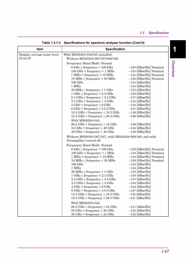
1.3 Specifications
1-47
1
Overview
Table 1.3.1-3 Specifications for spectrum analyzer function (Cont’d)
Item Specification Display average noise level (Cont’d)
With MS2830A-044/045 installed, Without MS2830A-067/167/068/168. Frequency Band Mode: Normal
9 kHz ≤ frequency < 100 kHz –120 [dBm/Hz] Nominal 100 kHz < frequency < 1 MHz –134 [dBm/Hz] Nominal 1 MHz < frequency < 10 MHz –144 [dBm/Hz] Nominal 10 MHz ≤ frequency < 30 MHz –150 [dBm/Hz] Nominal 100 kHz –134 [dBm/Hz] 1 MHz –144 [dBm/Hz] 30 MHz ≤ frequency < 1 GHz –153 [dBm/Hz] 1 GHz ≤ frequency < 2.4 GHz –150 [dBm/Hz] 2.4 GHz ≤ frequency ≤ 3.5 GHz –147 [dBm/Hz] 3.5 GHz < frequency ≤ 4 GHz –144 [dBm/Hz] 4 GHz < frequency ≤ 6 GHz –144 [dBm/Hz] 6 GHz < frequency ≤ 13.5 GHz –151 [dBm/Hz] 13.5 GHz < frequency ≤ 18.3 GHz –149 [dBm/Hz] 18.3 GHz < frequency ≤ 26.5 GHz –146 [dBm/Hz] With MS2830A-045, 26.5 GHz < frequency ≤ 34 GHz –146 [dBm/Hz] 34 GHz < frequency ≤ 40 GHz –144 [dBm/Hz] 40 GHz < frequency ≤ 43 GHz –140 [dBm/Hz]
Without MS2830A-067/167, with MS2830A-068/168, and with Preamplifier turned off. Frequency Band Mode: Normal
9 kHz ≤ frequency < 100 kHz –120 [dBm/Hz] Nominal 100 kHz < frequency < 1 MHz –134 [dBm/Hz] Nominal 1 MHz < frequency < 10 MHz –144 [dBm/Hz] Nominal 10 MHz ≤ frequency < 30 MHz –150 [dBm/Hz] Nominal 100 kHz –134 [dBm/Hz] 1 MHz –144 [dBm/Hz] 30 MHz ≤ frequency < 1 GHz –153 [dBm/Hz] 1 GHz ≤ frequency < 2.4 GHz –150 [dBm/Hz] 2.4 GHz ≤ frequency ≤ 3.5 GHz –147 [dBm/Hz] 3.5 GHz < frequency ≤ 4 GHz –144 [dBm/Hz] 4 GHz < frequency ≤ 6 GHz –144 [dBm/Hz] 6 GHz < frequency ≤ 13.5 GHz –147 [dBm/Hz] 13.5 GHz < frequency ≤ 18.3 GHz –145 [dBm/Hz] 18.3 GHz < frequency ≤ 26.5 GHz –141 [dBm/Hz] With MS2830A-045, 26.5 GHz < frequency ≤ 34 GHz –141 [dBm/Hz] 34 GHz < frequency ≤ 40 GHz –135 [dBm/Hz] 40 GHz < frequency ≤ 43 GHz –132 [dBm/Hz]

Chapter 1 Overview
1-48
Table 1.3.1-3 Specifications for spectrum analyzer function (Cont’d)
Item Specification Display average noise level (Cont’d)
Without MS2830A-067/167 or with Microwave Preselector Bypass turned off, with MS2830A-068/168, and with Preamplifier turned on. Frequency Band Mode: Normal
100 kHz –147 [dBm/Hz] Nominal 1 MHz –156 [dBm/Hz] 30 MHz ≤ frequency < 1 GHz –163 [dBm/Hz] 1 GHz ≤ frequency < 2 GHz –161 [dBm/Hz] 2 GHz ≤ frequency ≤ 3.5 GHz –159 [dBm/Hz] 3.5 GHz < frequency ≤ 4 GHz –155 [dBm/Hz] 4 GHz < frequency ≤ 6 GHz –155 [dBm/Hz] 6 GHz < frequency ≤ 13.5 GHz –160 [dBm/Hz] 13.5 GHz < frequency ≤ 18.3 GHz –158 [dBm/Hz] 18.3 GHz < frequency ≤ 26.5 GHz –156 [dBm/Hz] With MS2830A-045, 26.5 GHz < frequency ≤ 34 GHz –156 [dBm/Hz] 34 GHz < frequency ≤ 40 GHz –150 [dBm/Hz] 40 GHz < frequency ≤ 43 GHz –147 [dBm/Hz]
Absolute amplitude accuracy
After CAL execution at 18 to 28ºC, Auto Sweep Time Select = Normal, 30 Hz ≤ RBW ≤ 1 MHz, Detection = Positive, CW, excluding the noise floor effect, and not when FFT is being executed (displayed on the screen). With Preamplifier turned off: Input attenuator ≥ 10 dB, Mixer input level ≤ –10 dBm With Preamplifier turned on: Input attenuator = 10 dB, preamplifier input level ≤ –20 dBm, With MS2830A-040/041/043 installed,
Without MS2830A-008/108, or with Preamplifier turned off ±0.5 dB
(300 kHz ≤ frequency < 4 GHz, Frequency Band Mode: Normal) (300 kHz ≤ frequency < 3.5 GHz, Frequency Band Mode: Spurious)
±1.8 dB (4 GHz ≤ frequency ≤ 6 GHz, Frequency Band Mode: Normal) (3.5 GHz ≤ frequency ≤ 6 GHz, Frequency Band Mode: Spurious)
±1.8 dB (6 GHz < frequency ≤ 13.5 GHz)
With MS2830A-008/108 and with Preamplifier turned on ±1.0 dB
(300 kHz ≤ frequency < 4 GHz, Frequency Band Mode: Normal) (300 kHz ≤ frequency < 3.5 GHz, Frequency Band Mode: Spurious)
±1.8 dB (4 GHz ≤ frequency ≤ 6 GHz, Frequency Band Mode: Normal) (3.5 GHz ≤ frequency ≤ 6 GHz, Frequency Band Mode: Spurious)
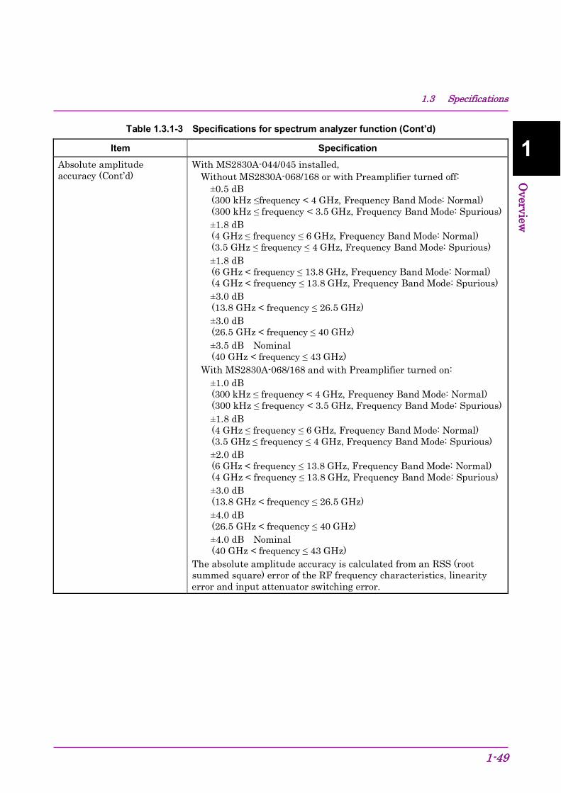
1.3 Specifications
1-49
1
Overview
Table 1.3.1-3 Specifications for spectrum analyzer function (Cont’d)
Item Specification Absolute amplitude accuracy (Cont’d)
With MS2830A-044/045 installed, Without MS2830A-068/168 or with Preamplifier turned off: ±0.5 dB
(300 kHz ≤frequency < 4 GHz, Frequency Band Mode: Normal) (300 kHz ≤ frequency < 3.5 GHz, Frequency Band Mode: Spurious)
±1.8 dB (4 GHz ≤ frequency ≤ 6 GHz, Frequency Band Mode: Normal) (3.5 GHz ≤ frequency ≤ 4 GHz, Frequency Band Mode: Spurious)
±1.8 dB (6 GHz < frequency ≤ 13.8 GHz, Frequency Band Mode: Normal) (4 GHz < frequency ≤ 13.8 GHz, Frequency Band Mode: Spurious)
±3.0 dB (13.8 GHz < frequency ≤ 26.5 GHz)
±3.0 dB (26.5 GHz < frequency ≤ 40 GHz)
±3.5 dB Nominal (40 GHz < frequency ≤ 43 GHz)
With MS2830A-068/168 and with Preamplifier turned on: ±1.0 dB
(300 kHz ≤ frequency < 4 GHz, Frequency Band Mode: Normal) (300 kHz ≤ frequency < 3.5 GHz, Frequency Band Mode: Spurious)
±1.8 dB (4 GHz ≤ frequency ≤ 6 GHz, Frequency Band Mode: Normal) (3.5 GHz ≤ frequency ≤ 4 GHz, Frequency Band Mode: Spurious)
±2.0 dB (6 GHz < frequency ≤ 13.8 GHz, Frequency Band Mode: Normal) (4 GHz < frequency ≤ 13.8 GHz, Frequency Band Mode: Spurious)
±3.0 dB (13.8 GHz < frequency ≤ 26.5 GHz)
±4.0 dB (26.5 GHz < frequency ≤ 40 GHz)
±4.0 dB Nominal (40 GHz < frequency ≤ 43 GHz)
The absolute amplitude accuracy is calculated from an RSS (root summed square) error of the RF frequency characteristics, linearity error and input attenuator switching error.

Chapter 1 Overview
1-50
Table 1.3.1-3 Specifications for spectrum analyzer function (Cont’d)
Item Specification Spurious Response Two-tone third-order intermodulation distortion
With MS2830A-040/041/043 Without MS2830A-008/108, or with Preamplifier turned off: At 18 to 28°C, with mixer input level = –15 dBm (per tone) and using ≥ 300 kHz separation, at RBW ≤ 30 kHz:
≤ –54 dBc (TOI = +12 dBm) (30 MHz ≤ frequency < 300 MHz) ≤ –60 dBc (TOI = +15 dBm) (300 MHz ≤ frequency < 3.5 GHz) ≤ –58 dBc (TOI = +14 dBm) (3.5 GHz ≤ frequency ≤ 6 GHz) ≤ –50 dBc (TOI = +10 dBm) (6 GHz ≤ frequency ≤ 13.5 GHz)
With MS2830A-008/108 installed and with Preamplifier turned on At 18 to 28°C, with Preamplifier input level = –45 dBm (per wave) and using ≥ 300 kHz separation, at RBW ≤30 kHz:
≤ –73 dBc (TOI = –8.5 dBm) (30 MHz ≤ frequency < 300 MHz) ≤ –78 dBc (TOI = –6 dBm) (300 MHz ≤ frequency ≤ 700 MHz) ≤ –81 dBc (TOI = –4.5 dBm) (700 MHz ≤ frequency < 4 GHz, Frequency Band Mode: Normal) (700 MHz ≤ frequency < 3.5 GHz, Frequency Band Mode: Spurious) ≤ –78 dBc (TOI = –6 dBm) (4 GHz ≤ frequency ≤ 6 GHz, Frequency Band Mode: Normal) (3.5 GHz ≤ frequency ≤ 6 GHz, Frequency Band Mode: Spurious)
With MS2830A-044/045 installed Without MS2830A-068/168 or with Preamplifier turned off, At 18 to 28°C, with mixer input level = –15 dBm (per wave) and using ≥ 300 kHz separation, at RBW ≤30 kHz:
≤ –54 dBc (TOI = +12 dBm) (30 MHz ≤ frequency < 300 MHz) ≤ –60 dBc (TOI = +15 dBm) (300 MHz ≤ frequency < 3.5 GHz) ≤ –58 dBc (TOI = +14 dBm) (3.5 GHz ≤ frequency ≤ 6 GHz, Frequency Band Mode: Normal) ≤–56 dBc (TOI = +13 dBm) (6 GHz < frequency ≤ 13.5 GHz) ≤ –56 dBc (TOI = +13 dBm) (13.5 GHz < frequency ≤ 26.5 GHz) ≤ –56 dBc (TOI = +13 dBm) Nominal (26.5 GHz < frequency ≤ 40 GHz) With MS2830A-045 installed

1.3 Specifications
1-51
1
Overview
Table 1.3.1-3 Specifications for spectrum analyzer function (Cont’d)
Item Specification Two-tone third-order intermodulation distortion (Cont’d)
With MS2830A-044/045 installed With MS2830A-067/167 and with Microwave Preselector Bypass turned off, and with MS2830A-068/168 and with Preamplifier turned on, At 18 to 28°C, with Preamplifier input level = –45 dBm (per wave) and using ≥ 300 kHz separation, at RBW ≤ 30 kHz:
≤ –73 dBc (TOI = –8.5 dBm) (30 MHz ≤ frequency < 300 MHz) ≤ –78 dBc (TOI = –6 dBm) (300 MHz ≤ frequency ≤ 700 MHz) ≤ –81 dBc (TOI = –4.5 dBm) (700 MHz < frequency < 4 GHz, Frequency Band Mode: Normal) (700 MHz < frequency < 3.5 GHz, Frequency Band Mode: Spurious) ≤ –78 dBc (TOI = –6 dBm) (4 GHz ≤ frequency ≤ 6 GHz, Frequency Band Mode: Normal) (3.5 GHz ≤ frequency ≤ 4 GHz, Frequency Band Mode: Spurious) ≤ –70 dBc (TOI = –10 dBm) (6 GHz < frequency ≤ 13.5 GHz, Frequency Band Mode: Normal) (4 GHz < frequency ≤ 13.5 GHz, Frequency Band Mode: Spurious) ≤ –70 dBc (TOI = –10 dBm) (13.5 GHz < frequency ≤ 26.5 GHz) ≤ –70 dBc (TOI = –10 dBm) Nominal (26.5 GHz < frequency ≤ 40 GHz) With MS2830A-045 installed
When Attenuator Mode is E-ATT Combined: Without MS2830A-008/108/068/168 and with Preamplifier turned off, at 18 to 28°C, with mixer input level = –15 dBm (per wave) and using ≥ 300 kHz separation, at RBW ≤30 kHz:
≤ –54 dBc (TOI = +12 dBm) (30 MHz ≤ frequency < 300 MHz, RF input level ≤ –5 dBm) ≤ –60 dBc (TOI = +15 dBm) (300 MHz ≤ frequency ≤ 1 GHz, RF input level ≤ –5 dBm) ≤ –60 dBc (TOI = +15 dBm) (1 GHz < frequency < 3.5 GHz, RF input level ≤ +5 dBm) ≤ –58 dBc (TOI = +14 dBm) (3.5 GHz ≤ frequency ≤ 6 GHz, Frequency Band Mode: Normal, RF input level ≤ +5 dBm) ≤ –54 dBc (TOI = +12 dBm) Nominal (30 MHz≤ frequency < 300 MHz, RF input level ≤0 dBm) ≤ –60 dBc (TOI = +15 dBm) Nominal (300 MHz ≤ frequency < 3.5 GHz, RF input level ≤+15 dBm) ≤ –58 dBc (TOI = +14 dBm) Nominal (3.5 GHz ≤ frequency ≤ 6 GHz, Frequency Band Mode: Normal, RF input level ≤+15 dBm)

Chapter 1 Overview
1-52
Table 1.3.1-3 Specifications for spectrum analyzer function (Cont’d)
Item Specification Image response With MS2830A-040/041/043 installed,
Frequency Band Mode: Normal ≤ –70 dBc (10 MHz ≤ frequency < 4 GHz) ≤ –55 dBc (4 GHz ≤ frequency ≤ 6 GHz) ≤ –60 dBc (6 GHz < frequency ≤ 13.5 GHz)
With MS2830A-062 installed and operating (Opt-062 enabled, 3.6 GHz max. center frequency, ≤ 1 MHz SPAN as spectrum analyzer)
≤ –10 dBc (This is generated at “input signal + 150 MHz”.) (330 MHz ≤ frequency < 3.6 GHz)
With MS2830A-066 installed and operating (066: Enabled, Center frequency: 3.6 GHz or less, and SPAN ≤ 1 MHz as spectrum analyzer).
≤ –10 dBc (This is generated at “input signal + 150 MHz”.) (110 MHz ≤ frequency < 3.6 GHz)
With MS2830A-044/045 installed, When MS2830A-067/167 is NOT installed
≤ –70 dBc (10 MHz ≤ frequency < 4 GHz) ≤ –55 dBc (4 GHz ≤ frequency ≤ 6 GHz) ≤ –70 dBc (6 GHz < frequency ≤ 13.5 GHz) ≤ –70 dBc (13.5 GHz < frequency ≤ 26.5 GHz)
Multiple Response (330 MHz ≤ Frequency < 3.6 GHz)
With MS2830A-040/041/043 installed, With MS2830A-062/066 installed and operating (Opt-062/066 enabled, 3.6 GHz max. center frequency, SPAN ≤ 1 MHz as spectrum analyzer), and –15 dBm mixer input level
≤ –10 dBc Nominal
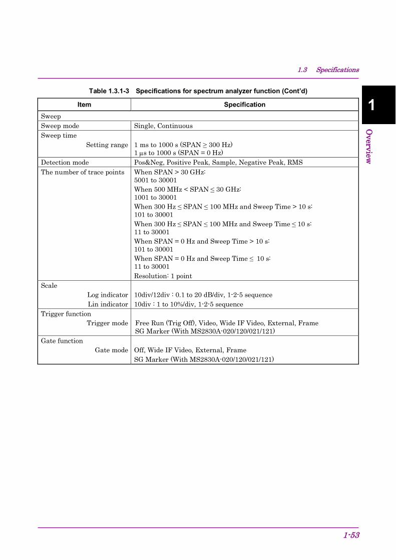
1.3 Specifications
1-53
1
Overview
Table 1.3.1-3 Specifications for spectrum analyzer function (Cont’d)
Item Specification Sweep Sweep mode Single, Continuous Sweep time
Setting range 1 ms to 1000 s (SPAN ≥ 300 Hz) 1 µs to 1000 s (SPAN = 0 Hz)
Detection mode Pos&Neg, Positive Peak, Sample, Negative Peak, RMS The number of trace points When SPAN > 30 GHz:
5001 to 30001 When 500 MHz < SPAN ≤ 30 GHz: 1001 to 30001 When 300 Hz ≤ SPAN ≤ 100 MHz and Sweep Time > 10 s: 101 to 30001 When 300 Hz ≤ SPAN ≤ 100 MHz and Sweep Time ≤ 10 s: 11 to 30001 When SPAN = 0 Hz and Sweep Time > 10 s: 101 to 30001 When SPAN = 0 Hz and Sweep Time ≤ 10 s: 11 to 30001 Resolution: 1 point
Scale Log indicator Lin indicator
10div/12div : 0.1 to 20 dB/div, 1-2-5 sequence 10div : 1 to 10%/div, 1-2-5 sequence
Trigger function Trigger mode
Free Run (Trig Off), Video, Wide IF Video, External, Frame SG Marker (With MS2830A-020/120/021/121)
Gate function Gate mode
Off, Wide IF Video, External, Frame SG Marker (With MS2830A-020/120/021/121)

Chapter 1 Overview
1-54
Table 1.3.1-3 Specifications for spectrum analyzer function (Cont’d)
Item Specification Measurement function Adjacent Channel Power Measurement (ACP)
Reference Adjacent channel
specification
Span Total, Carrier Total, Both Sides of Carriers or Carrier Select 3 channels × 2 (Normal Mode) 8 channels × 2 (Advanced Mode)
Burst arrange Indicates average power of specified time in the time domain mode. Channel Power
Absolute value measurement
dBm, dBm/Hz
Occupied Bandwidth (OBW) N% of Power method, X dB Down method Spectrum Emission Mask (SEM)
Peak/Margin measurement: Pass/fail judgment is performed by Peak/Margin measurement.
Spurious Emission Worst/Peaks measurement: Pass/fail judgment is performed by Worst/Peaks measurement
Frequency counter Counter accuracy
±(marker frequency × reference frequency accuracy + (0.1 × N/Gate Time[s])) Hz) at SPAN ≤ 1 MHz, RBW = 1 kHz, S/N ≤ 50 dB, Gate Time ≥ 100 ms Mixer harmonic order [N]
Two-tone third-order intermodulation distortion Measures IM3 and TOI from two-tone signal.
Signal Generator Control The DUT transfer characteristics can be measured by interlinking the internal signal generator and spectrum analyzer operations. MS2830A-052/152/352, and MS2830A-020/120/021/121/088/188 is required.
1.3.2 Rubidium Reference Oscillator Option (MS2830A-001/101) Table 1.3.2-1 Rubidium Reference Oscillator Specifications
Items Specifications Function and Performance See Table 1.3.1-1, “Internal reference oscillator”.
1.3.3 High Stability Reference Oscillator Option (MS2830A-002/102) Table 1.3.3-1 High Stability Reference Oscillator Option Specifications
Item Specification Function and Performance See Table 1.3.1-1, “Internal reference oscillator”. Others This option is not available when MS2830A-044/045 is installed.

1.3 Specifications
1-55
1
Overview
1.3.4 Preamplifier Option (MS2830A-008/108) Table 1.3.4-1 lists the specifications for the preamplifier.
The following specification values are those under the conditions after 30-min warm-up at stable ambient temperature. Typical values are only for reference and are not guaranteed.
Table 1.3.4-1 Preamplifier Option Specifications
Item Specification Frequency Frequency range 100 kHz to 3.6 GHz (With MS2830A-040)
100 kHz to 6 GHz (With MS2830A-041/043) Amplitude Measurement range See Table 1.3.1-1, “Measurement range”. Maximum input level See Table 1.3.1-1, “Maximum input level”. Display average noise level (Signal Analyzer function)
See Table 1.3.1-2, “Display average noise level”.
Display average noise level (Spectrum analyzer function)
See Table 1.3.1-3, “Display average noise level”.
RF Frequency Characteristics
See Table 1.3.1-1, “RF frequency characteristics”.
Input attenuator switching error
See Table 1.3.1-1, “Input attenuator switching error”.
Linearity error See Table 1.3.1-1, “Linearity error”. Second harmonic wave distortion
See Table 1.3.1-1, “Second harmonic wave distortion”.
1 dB gain compression See Table 1.3.1-1, “1 dB gain compression”. Two-tone third-order intermodulation distortion
See Table 1.3.1-3, “Two-tone third-order intermodulation distortion”.
Others Cannot install simultaneously with MS2830A-068/168.
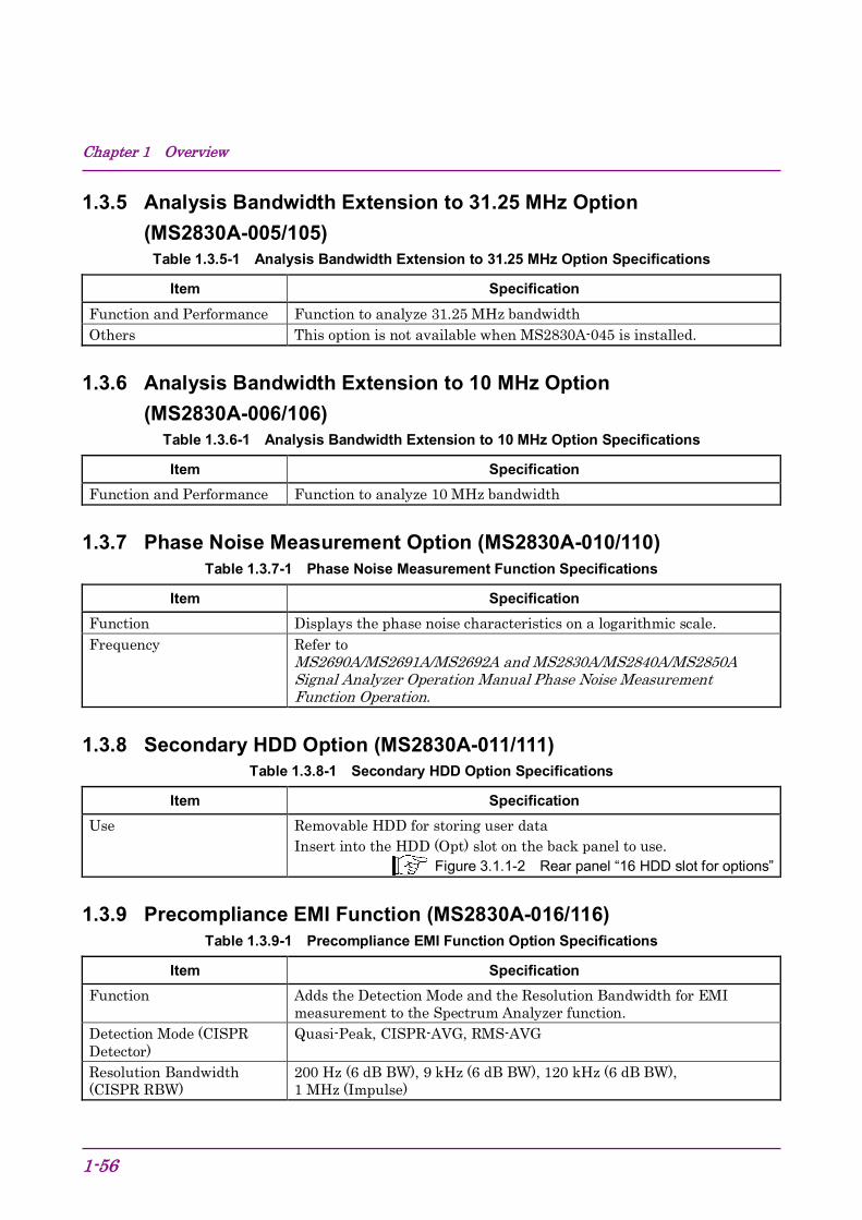
Chapter 1 Overview
1-56
1.3.5 Analysis Bandwidth Extension to 31.25 MHz Option (MS2830A-005/105)
Table 1.3.5-1 Analysis Bandwidth Extension to 31.25 MHz Option Specifications
Item Specification Function and Performance Function to analyze 31.25 MHz bandwidth Others This option is not available when MS2830A-045 is installed.
1.3.6 Analysis Bandwidth Extension to 10 MHz Option (MS2830A-006/106)
Table 1.3.6-1 Analysis Bandwidth Extension to 10 MHz Option Specifications
Item Specification Function and Performance Function to analyze 10 MHz bandwidth
1.3.7 Phase Noise Measurement Option (MS2830A-010/110) Table 1.3.7-1 Phase Noise Measurement Function Specifications
Item Specification Function Displays the phase noise characteristics on a logarithmic scale. Frequency
Refer to MS2690A/MS2691A/MS2692A and MS2830A/MS2840A/MS2850A Signal Analyzer Operation Manual Phase Noise Measurement Function Operation.
1.3.8 Secondary HDD Option (MS2830A-011/111) Table 1.3.8-1 Secondary HDD Option Specifications
Item Specification Use Removable HDD for storing user data
Insert into the HDD (Opt) slot on the back panel to use. Figure 3.1.1-2 Rear panel “16 HDD slot for options”
1.3.9 Precompliance EMI Function (MS2830A-016/116) Table 1.3.9-1 Precompliance EMI Function Option Specifications
Item Specification Function Adds the Detection Mode and the Resolution Bandwidth for EMI
measurement to the Spectrum Analyzer function. Detection Mode (CISPR Detector)
Quasi-Peak, CISPR-AVG, RMS-AVG
Resolution Bandwidth (CISPR RBW)
200 Hz (6 dB BW), 9 kHz (6 dB BW), 120 kHz (6 dB BW), 1 MHz (Impulse)
1.3 Specifications
1-57
1
Overview
1.3.10 Low Phase Noise Performance Option (MS2830A-062/066) Summary: The SSB phase noise is improved for RF input signals by provision of an internal dedicated frequency converter. Near-carrier phase noise is reduced by installing the Low Phase Noise option (MS2830A-062/066) and turning On the Low Phase Noise option function.
Example of Improvement: The Low Phase Noise Performance option brings the following improvements in the measurement of narrow-band radio device (radio for commercial use) and of transmitter for digital TV broadcasting.
Allows near-carrier spurious measurement.
The adjacent channel power (ACP) measurement is performed with accuracy because noise power over the adjacent channel is reduced.
S/N and EVM are improved due to reduced residual FM.
Precautions when Low Phase Noise option enabled (On). The operation principle of the frequency converter is generation of a spurious response at a specific frequency. As a result, sometimes it is better not to use, such as when measuring spurious.
When the DUT signal frequency is known, when the MS2830A Rx frequency is set to 35 MHz beyond that frequency, measurement can be made as if the Low Phase Noise Function is Off (disabled) because the spurious response cannot be observed.
However, even if the DUT signal frequency is unknown, measurement can be made after setting the Low Phase Noise Function to Off (disabled) and verifying the presence of a response at about the same level (in other words, confirming that the observed signal has the correct response).
The spurious responses are as follows:
(1) Image Response This response is generated when a signal with frequency fin is input to the MS2830A RF input connector and the MS2830A Rx frequency is set to fin –150 MHz, and more than 330 MHz (with MS2830A-062) or more than 110 MHz (with MS2830A-066). The generated level is about –20 dBc.
Chapter 1 Overview
1-58
(2) Multiple Response This response is generated when a signal with frequency fin is input to the MS2830A RF input connector and the MS2830A Rx frequency is set to (fin ±75 MHz)/N–75 MHz (N = 1,2,3 …),and more than 330 MHz (with MS2830A-062) or more than 110 MHz (with MS2830A-066). The generated level is about –10 dBc.
Table 1.3.10-1 Low Phase Noise Performance Specifications
Item Specification Frequency Frequency Range
9 kHz to 3.7 GHz 9 kHz to 3.5 GHz (Frequency Band Mode: Spurious)
SPAN 1 kHz to 31.25 MHz (Signal Analyzer function) 300 Hz to 1 MHz (Spectrum Analyzer function)
Single side band noise See Table 1.3.1-1, “Single side band noise”. Resolution bandwidth (RBW)
See Table 1.3.1-3, “Specifications for spectrum analyzer function, Resolution bandwidth (RBW)”.
Amplitude Display average noise level (Signal Analyzer function)
See Table 1.3.1-2, “Specifications for Signal Analyzer Function, Display average noise level”.
Display average noise level (Spectrum analyzer function)
See Table 1.3.1-3, “Specifications for spectrum analyzer function, Display average noise level”.
Spurious Response Image response See Table 1.3.1-3, “Specifications for spectrum analyzer function, Image
response”.
1.3.11 Removable HDD option (MS2830A-313) Table 1.3.11-1 Removable HDD Option Specification
Item Specification Use This is a spare hard disk for the MS2830A to replace the disk.
Insert into the HDD slot on the back panel to use. Figure 3.1.1-2 Rear panel “15 HDD slot”

1.3 Specifications
1-59
1
Overview
1.3.12 Microwave Preamplifier Option (MS2830A-068/168) This option amplifies signal prior to 1st mixer to enhance sensitivity.
This option is the wideband version of Preamplifier Option (MS2830A-008/108), and can be used on the application software in a similar way.
Table 1.3.12-1 Microwave Preamplifier Option Specifications
Item Specification Frequency Frequency range 100 kHz to 26.5 GHz (With MS2830A-044)
100 kHz to 43 GHz (With MS2830A-045) Amplitude Measurement range See Table 1.3.1-1, “Measurement range”. Maximum input level See Table 1.3.1-1, “Specifications for Mainframe, Maximum input
level”. Display average noise level (Signal Analyzer function)
See Table 1.3.1-2, “Specifications for Signal Analyzer Function, Display average noise level”.
Display average noise level (Spectrum analyzer function)
See Table 1.3.1-3, “Display average noise level”.
RF Frequency Characteristics
See Table 1.3.1-1, “Specifications for Mainframe, RF frequency characteristics”.
Input attenuator switching error
See Table 1.3.1-1, “Specifications for Mainframe, Input attenuator switching error”.
Linearity error See Table 1.3.1-1, “Specifications for Mainframe, Linearity error”. Second harmonic wave distortion
See Table 1.3.1-1, “Specifications for Mainframe, Second harmonic wave distortion”.
1 dB gain compression See Table 1.3.1-1, “Specifications for Mainframe, 1 dB gain compression”.
Two-tone third-order intermodulation distortion
See Table 1.3.1-3, “Specifications for spectrum analyzer function, Two-tone third-order intermodulation distortion”.
Others Cannot install simultaneously with MS2830A-008/108.

Chapter 1 Overview
1-60
1.3.13 Microwave Preselector Bypass Option (MS2830A-067/167) Summary:
By bypassing the preselector (image response elimination filter), the RF frequency characteristics and the in-band frequency characteristics are improved, and level accuracy improvement can be achieved.
Notes on default values when this option is installed: To improve the in-band frequency characteristics, the default value is set to On for the Signal Analyzer function, and is always set to On for all other applications.
To avoid measuring the image signals generated internally, the default value is set to Off for the Spectrum Analyzer function.
Table 1.3.13-1 Microwave Preselector Bypass Option Specifications
Item Specification Intended Use Bypasses the preselector to improve the RF frequency characteristics
and the in-band frequency characteristics. When this function is set to On, the image response elimination filter is bypassed. Therefore, this function is not appropriate for image response reception and spurious measurement.
Function and performance Frequency Frequency range 4 GHz to 26.5 GHz (MS2830A-044)
4 GHz to 43 GHz (MS2830A-045) Amplitude RF frequency characteristics After CAL execution at 18 to 28ºC, input attenuator = 10 dB,
With Microwave Preselector Bypass turned on, Without MS2830A-068/168 or with Preamplifier turned off:
±1.00 dB (6 GHz ≤ frequency ≤ 13.8 GHz, Frequency Band Mode: Normal) (4 GHz ≤ frequency ≤ 13.8 GHz, Frequency Band Mode: Spurious) ±1.50 dB (13.8 GHz < frequency ≤ 26.5 GHz) ±2.00 dB (26.5 GHz < frequency ≤ 40 GHz) ±2.00 dB typ. (40 GHz < frequency ≤ 43 GHz)

1.3 Specifications
1-61
1
Overview
Table 1.3.13-1 Microwave Preselector Bypass Option Specifications (Cont’d)
Item Specification RF frequency characteristics (Cont’d)
With Microwave Preselector Bypass turned on, With MS2830A-068/168 or with Preamplifier turned on:
±1.8 dB (6 GHz ≤ frequency ≤ 13.8 GHz, Frequency Band Mode: Normal) (4 GHz ≤ frequency ≤ 13.8 GHz, Frequency Band Mode: Spurious) ±2.50 dB (13.8 GHz < frequency ≤ 26.5 GHz) ±3.00 dB (26.5 GHz < frequency ≤ 40 GHz) ±3.00 dB Nominal (40 GHz < frequency ≤ 43 GHz)
Display average noise level At 18 to 28ºC, Detector = Sample, VBW = 1 Hz (Video Average) At input attenuator 0 dB, If the frequency ≤ 6 GHz, the specifications are the same as those in the state without MS2830A-067/167. Refer to Table 1.3.1-3 “Specifications for spectrum analyzer function: Display average noise level.” Irrespective of Microwave Preselector Bypass turned on/off, Without MS2830A-068/168 installed,
With MS2830A-044/045, 6 GHz < frequency ≤ 13.5 GHz –147 [dBm/Hz] 13.5 GHz < frequency ≤ 18.4 GHz –145 [dBm/Hz] 18.4 GHz < frequency ≤ 26.5 GHz –141 [dBm/Hz] With MS2830A-045, 26.5 GHz < frequency ≤ 34 GHz –141 [dBm/Hz] 34 GHz < frequency ≤ 40 GHz –135 [dBm/Hz] 40 GHz < frequency ≤ 43 GHz –132 [dBm/Hz]
With MS2830A-068/168 or with Preamplifier turned off: With MS2830A-044/045, 6 GHz < frequency ≤ 13.5 GHz –142 [dBm/Hz] 13.5 GHz < frequency ≤ 18.4 GHz –140 [dBm/Hz] 18.4 GHz < frequency ≤ 26.5 GHz –136 [dBm/Hz] With MS2830A-045, 26.5 GHz < frequency ≤ 34 GHz –136 [dBm/Hz] 34 GHz < frequency ≤ 40 GHz –131 [dBm/Hz] 40 GHz < frequency ≤ 43 GHz –128 [dBm/Hz]

Chapter 1 Overview
1-62
Table 1.3.13-1 Microwave Preselector Bypass Option Specifications (Cont’d)
Item Specification Display average noise level (Cont’d)
With Microwave Preselector Bypass turned on, With MS2830A-068/168 and with Preamplifier turned on:
With MS2830A-044/045, 6 GHz < frequency ≤ 13.5 GHz –154 [dBm/Hz] 13.5 GHz < frequency ≤ 18.4 GHz –152 [dBm/Hz] 18.4 GHz < frequency ≤ 26.5 GHz –150 [dBm/Hz] With MS2830A-045, 26.5 GHz < frequency ≤ 34 GHz –150 [dBm/Hz] 34 GHz < frequency ≤ 40 GHz –144 [dBm/Hz] 40 GHz < frequency ≤ 43 GHz –141 [dBm/Hz]
Image response With Microwave Preselector Bypass turned off, –60 dBc (6 GHz < frequency ≤ 13.5 GHz) –60 dBc (13.5 GHz < frequency ≤ 13.5 GHz)
With Microwave Preselector Bypass turned on, Generated at the frequency at the distance of 1875 MHz × 2
0 dBc Nominal (4 GHz < frequency ≤ 26.5 GHz) 0 dBc Nominal (26.5 GHz < frequency ≤ 43 GHz)
Others Cannot be installed together with MS2830A-007
1.3.14 Bandwidth Extension to 31.25 MHz with Preselector Bypass Option (MS2830A-007)
This option adds a function to analyze 31.25 MHz bandwidth and a preselector option to MS2830A-045. It can be used in a similar way as MS2830A-005/105 and MS2830A-067/167 on the application software.
Table 1.3.14-1 Bandwidth Extension to 31.25 MHz with Preselector Bypass - Option Specifications
Item Specification Application This option adds a function to analyze 31.25 MHz bandwidth and a
preselector option to MS2830A-045 (43 GHz Signal Analyzer). When the preselector option is set to On, the image response elimination filter is bypassed. Therefore, this function is not appropriate for image response reception and spurious measurement.
Function and performance Display average noise level Refer to Table 1.3.13-1 “Microwave Preselector Bypass Option
Specifications: Display average noise level.” RF frequency characteristics
Refer to Table 1.3.13-1 “Microwave Preselector Bypass Option Specifications: RF frequency characteristics.”
Others Cannot be installed together with MS2830A-067/167. Available only when MS2830A-045 is installed.

1.3 Specifications
1-63
1
Overview
1.3.15 Analysis Bandwidth Extension Option, 62.5 MHz (MS2830A-077/177)
Table 1.3.15-1 Analysis Bandwidth Extension to 62.5 MHz Option Specifications
Item Specification Application Extends the analysis bandwidth to 62.5 MHz in single analyzer mode
by bypassing a bandwidth-limiting filter such as a preselector and performing fast sampling. On the other hand, because an image response is received due to bypassing the image response elimination filter, this is not adequate for measuring spurious or out-of-analysis-band signals and analyzing signals.
ADC resolution 14 bits Display average noise level Refer to Table 1.3.1-2 “Specifications for Signal Analyzer Function:
Display average noise level” Image response With MS2830A-077/177 installed and Bandwidth > 31.25 MHz.
To be generated at a frequency that is 200 MHz away. 0 dBc Nominal (300 MHz < frequency ≤ 43 GHz)
With MS2830A-077/177 and MS2830A-067/167 installed and Bandwidth > 31.25 MHz.
To be generated at a frequency that is 1875 MHz × 2 away. 0 dBc Nominal (6 GHz < frequency ≤ 43 GHz)
Chapter 1 Overview
1-64
1.3.16 Analysis Bandwidth Extension Option, 125 MHz (MS2830A-078/178)
Table 1.3.16-1 Analysis Bandwidth Extension to 125 MHz Option Specifications
Item Specification Application Extends the analysis bandwidth to 125 MHz in single analyzer mode
by bypassing a bandwidth-limiting filter such as a preselector and performing fast sampling. On the other hand, because an image response is received due to bypassing the image response elimination filter, this is not adequate for measuring spurious or out-of-analysis-band signals and analyzing signals.
ADC resolution 14 bits Display average noise level Refer to Table 1.3.1-2 “Specifications for Signal Analyzer Function:
Display average noise level” Image response With MS2830A-078/178 installed and Bandwidth > 31.25 MHz.
To be generated at a frequency that is 200 MHz away. 0 dBc Nominal (300 MHz < frequency ≤ 43 GHz)
With MS2830A-078/178 and MS2830A-067/167 installed and Bandwidth > 31.25 MHz.
To be generated at a frequency that is 1875 MHz × 2 away. 0 dBc Nominal (6 GHz < frequency ≤ 43 GHz)
1.3.17 Bandwidth Extension to 31.25 MHz for Millimeter-wave (MS2830A-009/109)
Table 1.3.17-1 Bandwidth Extension to 31.25 MHz for Millimeter-wave Specifications
Item Specification Application Extends the analysis bandwidth to 31.25 MHz in signal analyzer mode. Others This option is available only when MS2830A-045 is installed.

1.3 Specifications
1-65
1
Overview
1.3.18 BER Measurement function (MS2830A-026/126) Table 1.3.18-1 BER Measurement function Specifications
Item Specification Connector Rear panel Aux connector Input level TTL level Input signal Data, Clock, Enable Input bit rate 100 bps to 10 Mbps
Measurable patterns PN9, PN11, PN15, PN20, PN23, ALL0, ALL1, repetition of 01 PN9Fix, PN11Fix, PN15Fix, PN20Fix, PN23Fix UserDefine (4096 bits max.)
Synchronization establishing condition
PN signal: No error has been detected for (PN stage count × 2) bits
PNFix signal: Synchronization with the PN signal is established if no error has been detected for (PN stage count × 2) bits. Next, the cycle and synchronization of the PNFix signal are established if no error has been detected for PN stage count bits beginning with the start bit of the PNFix signal.
ALL0, ALL1, repetition of 01: No error has been detected for 10 bits.
UserDefine: No error has been detected for 8 to 1024 bits (variable). The start bit used for synchronization detection can also be selected.
Re-synchronization judgment condition
x/y (Resynchronization is executed if x bits out of y bits are errors.) y (Measurement bit count): Selected from 500 bits, 5000 bits,
and 50000 bits x (Error bit count out of y bits): 1 to y/2 bits
Measurable bit count ≤ 232 − 1 bits Measurable error bit count ≤ 231 − 1 bits Measurement termination condition Measurement bit count, measurement error bit count
Auto Resync function Can be switched between enable/disable. Count operation at resynchronization Can be selected from Count Clear and Count Keep.
Measurement mode Continuous, Single, Endless
Display Status, Error, Sync Loss, Error Rate, Error Count, SyncLoss Count Measurement bit count
Polarity reversal function Data, Clock, and Enable polarities can be reversed.
Measured value clear function
It is possible to clear the measured values to 0 while retaining synchronization during BER measurement, and start the measurement again from 0.

Chapter 1 Overview
1-66
1.3.19 Audio Analyzer Option (MS2830A-018/118) This option adds the audio generator and audio analyzer function.
For specifications of the Audio Analyzer, refer to the MX269018A Analog Measurement Software/MS2830A Signal Analyzer Analog Signal Generator Operation Manual.
1.3.20 Two-handle Frame with Connecting Parts (for Single-handle Frame) (MS2830A-171)
This is an option to connect singled-handled MS2830A with a measurement module like the MN2555A Duplexer Box.
1.3.21 Connecting parts (for two-handle frame) (MS2830A-081/181) This is an option to connect doubled-handled MS2830A with a measurement module like the MN2555A Duplexer Box.
1.3.22 3.6 GHz Analog Signal Generator Option (MS2830A-088/188)
Table 1.3.22-1 3.6 GHz Analog Signal Generator Option Specifications
Item Specification Application Adds the analog signal generator function to MS2830A.
1.3.23 Vector Function Extension for Analog Signal Generator Option (MS2830A-189)
Table 1.3.23-1 Vector Function Extension for Analog Signal Generator Option Specifications
Item Specification Application Adds the vector modulation function to MS2830A-088/188.
1.3 Specifications
1-67
1
Overview
1.3.24 Internal Signal Generator Control Function Option (MS2830A-052/152/352)
Table 1.3.24-1 Internal Signal Generator Control Function Option Specifications
Item Specification Application The DUT transfer characteristics can be measured by interlinking the
internal signal generator and spectrum analyzer operations. Others This option is available only when one of the following options is
installed. MS2830A-020/120, MS2830A-021/121, MS2830A-088/188
User needs to install the license before using the MS2830A-352 Internal Signal Generator Control Function User-installable. For how to install the license, refer to “Installing software or licenses” in 3.8.1 “Installing software or hardware licenses”.
1.3.25 Noise Figure Measurement Function Option (MS2830A-017/117) Table 1.3.25-1 Noise Figure Measurement Function Option Specifications
Item Specification
Function Adds the function to measure Noise Figure, Noise Factor, Gain and Y factor.
Frequency Refer to MS2690A/MS2691A/MS2692A and MS2830A/MS2840A/MS2850A Signal Analyzer Operation Manual Noise Figure Measurement Function Operation.
Noise Figure Gain Resolution Bandwidth
1.3.26 Rubidium Reference Oscillator Option (MS2830A-037/137) Table 1.3.26-1 Rubidium Reference Oscillator Specifications
Items Specifications Function and Performance See Table 1.3.1-1, “Internal reference oscillator”.

Chapter 1 Overview
1-68.

2-1
2 Before U
se
Before Use Chapter 2 This chapter describes items that you should know before using the MS2830A. Be sure to read this section at least once as it contains safety tips and cautions for avoiding failure during use.
2.1 Installation Location ...................................................... 2-2 2.1.1 Installation orientation....................................... 2-2 2.1.2 Distance from surrounding objects ................... 2-3 2.1.3 Installation location conditions .......................... 2-3
2.2 Items to Check Before Use ........................................... 2-4 2.2.1 Safety labels ..................................................... 2-4 2.2.2 Input level and reverse power (when vector
signal generator is installed) to RF Input ....... 2-5 2.2.3 Electrostatic ...................................................... 2-6 2.2.4 Notes on handling input connector and SG
output connector (when vector signal generator is installed) ....................................... 2-8
2.2.5 USB memory stick ............................................ 2-8 2.3 Power Connection ........................................................ 2-9
2.3.1 Power requirements ......................................... 2-9 2.3.2 Connecting power cord..................................... 2-9

Chapter 2 Before Use
2-2
2.1 Installation Location 2.1.1 Installation orientation
Install the MS2830A horizontally or at an angle using the tilted legs as shown in Figure 2.1.1-1. Do not place objects on top of the MS2830A when tilted.
Figure 2.1.1-1 Installation orientation
CAUTION If the MS2830A is not installed in a “OK” direction as above, a small shock may turn it over and harm the user.
NG OK

2.1 Installation Location
2-3
2 Before U
se
2.1.2 Distance from surrounding objects A fan is installed to the MS2830A to prevent the internal temperature from rising. Install the MS2830A in a location with the vents at least 10 cm away from walls, peripherals or other obstructions so as not to block the fan perimeter.
Figure 2.1.2-1 Distance from surrounding objects
2.1.3 Installation location conditions Although the MS2830A operates at an ambient temperature of 5° to 45°C, avoid using it in locations, such as the following, since it may cause failure.
Locations with strong vibrations Humid and dusty locations Locations with direct sunlight Locations where there is the risk of exposure to active gases Locations where power voltage severely fluctuates
At least 10 cm space
At least 10 cm space
At least 10 cm space
At least 10 cm space

Chapter 2 Before Use
2-4
2.2 Items to Check Before Use 2.2.1 Safety labels
To protect the safety of the user, the WARNING label shown in Figure 2.2.1-1 is affixed to the rear panel. Observe the instructions on the label.
Figure 2.2.1-1 Warning labels
WARNING THIS MEASURING EQUIPMENT IS A PRECISION ELECTRONIC DEVICE THAT CONTAINS HAZARDOUS PARTS, AND THEREFORE MUST NOT BE SERVICED BY THE CUSTOMER. UNDER NO CIRCUMSTANCES DISASSEMBLE THIS EQUIPMENT. THIS EQUIPMENT MUST BE SERVICED ONLY BY QUALIFIED SERVICE PERSONNEL.

2.2 Items to Check Before Use
2-5
2 Before U
se
2.2.2 Input level and reverse power (when vector signal generator is installed) to RF Input
The MS2830A is not provided with over-power protection. Be careful not to apply the power to the RF Input connector as described below:
For Option 040/041/043, without Option 008/108 installed, or with Preamplifier turned off:
+30 dBm Max (Input attenuator ≥10 dB), ±10 Vdc Max For Option 040/041/043, with Option 008/108 installed, and with Preamplifier turned on:
+10 dBm Max (Input attenuator = 0 dB), ±10 Vdc Max
For Option 044/045, without Option 068/168 installed, or with Preamplifier turned off:
+30 dBm Max (Input attenuator ≥ 10 dB), ±0 Vdc Max For Option 044/045, with Option 068/168 installed, and with Preamplifier turned on:
+10 dBm Max (Input attenuator = 0 dB), ±0 Vdc Max There is no reverse power protection for the SG output connector when the Vector Signal Generator Option is installed. Be careful not to apply reverse power to the SG Output connector as described below: When Option 022/122 is NOT installed:
+12 dBm Max (<20 MHz), +24 dBm Max (≥20 MHz) When Option 022/122 is installed:
+18 dBm Max (<20 MHz), +30 dBm Max (≥20 MHz) In addition, do not apply DC voltage even when within the range described above.

Chapter 2 Before Use
2-6
2.2.3 Electrostatic
CAUTION Always use the supplied 3-pin power cord to ground
both the MS2830A and DUT (included in test circuit). After confirming that both the MS2830A and DUT are grounded, use coaxial cables to connect them. NEVER connect the MS2830A and DUT without grounding, otherwise electrostatic discharge may damage the MS2830A.
Do not touch the core conductor of the connector or bring it into contact with metal. Doing so may damage the input circuit of the MS2830A.

2.2 Items to Check Before Use
2-7
2 Before U
se
CAUTION Do not touch the core conductor of the coaxial cable connected to the input connector or bring it into contact with metal.
Doing so may damage the input circuit of the MS2830A.
CAUTION Do not touch the core conductor to the metal when connecting the coaxial cable to the connector.
Doing so may damage the input circuit of the MS2830A.

Chapter 2 Before Use
2-8
2.2.4 Notes on handling input connector and SG output connector (when vector signal generator is installed)
For Option 040/041/043, only connect N-type connector to RF Input and SG Output. For Option 044, only connect N-type connector and for Option 045, only connect K-type connector to RF Input. Connecting a different connector will damage the connector.
2.2.5 USB memory stick Note the orientation of the connection when using a USB memory stick. Plugging in a USB memory stick in the wrong direction may damage the connector.

2.3 Power Connection
2-9
2 Before U
se
2.3 Power Connection This section describes the procedures for supplying power.
2.3.1 Power requirements For normal operation of the MS2830A, observe the power voltage range described below.
Power source Voltage range Frequency
100 Vac system 100 to 120 V 50 to 60 Hz 200 Vac system 200 to 240 V 50 to 60 Hz
Operating voltage is within the range of +10% to –15% from the rated voltage (Max. 250 V). Changeover between 100 and 200 V system is made automatically. The maximum power consumption of the MS2830A is 350 VA. Provide sufficient power capacity.
CAUTION Supplying power exceeding the above range may result in electrical shock, fire, failure, or malfunction.
2.3.2 Connecting power cord Insert the power plug into a grounded outlet, and connect the other end to the power inlet on the rear panel. To ensure that the instrument is properly grounded, always use the supplied 3-pin power cord.

Chapter 2 Before Use
2-10.
WARNING Always connect the instrument to a properly grounded outlet. Do not use the instrument with an extension cord or transformer that does not have a ground wire.
If the instrument is connected to an ungrounded outlet, there is a risk of receiving a fatal electric shock. In addition, the peripheral devices connected to the instrument may be damaged.
Unless otherwise specified, the signal-connector ground terminal, like an external conductor of the coaxial connector, of the instrument is properly grounded when connecting the power cord to a grounded outlet. Connect the ground terminal of DUT to a ground having the same potential before connecting with the instrument. Failure to do so may result in an electric shock, fire, failure, or malfunction.
CAUTION If an emergency arises causing the instrument to fail or malfunction, disconnect the instrument from the power supply by disconnecting either end of the power cord.
When installing the instrument, place the instrument so that an operator may easily connect or disconnect the power cord from the power inlet and outlet. Moreover, DO NOT fix the power cord around the plug and the power inlet with a holding clamp or similar device.
If the instrument is mounted in a rack, a power switch for the rack or a circuit breaker may be used for power disconnection.
It should be noted that, the power switch on the front panel of the instrument is a standby switch, and cannot be used to cut the main power.

3-1
3
Com
mon
Operation
s
Common Operations Chapter 3
This chapter describes items to be understood before actually operating the MS2830A, including part names, basic parameter setting methods, modulation operation method and useful functions.
3.1 Part Names ................................................................... 3-2 3.1.1 Part names ....................................................... 3-2
3.2 Turning Power On/Off ................................................. 3-11 3.2.1 Turning power On ........................................... 3-11 3.2.2 Turning power Off ........................................... 3-12
3.3 Auto Calibration .......................................................... 3-14 3.4 Settings on Configuration Screen ............................... 3-17
3.4.1 Display description ......................................... 3-18 3.4.2 Interface Settings ............................................ 3-19 3.4.3 Copy Settings ................................................. 3-20 3.4.4 System Settings .............................................. 3-21 3.4.5 Application Switch Settings ............................ 3-24 3.4.6 System Information ......................................... 3-25 3.4.7 Option Information .......................................... 3-26 3.4.8 File Operation ................................................. 3-26 3.4.9 Software Install/Uninstall ................................ 3-27 3.4.10 Correction ....................................................... 3-27 3.4.11 Display Annotation .......................................... 3-31 3.4.12 Calibration Alert .............................................. 3-32
3.5 Loading, Unloading, and Switching Applications ........ 3-34 3.5.1 Loading applications ....................................... 3-35 3.5.2 Unloading applications ................................... 3-37 3.5.3 Switching applications .................................... 3-39 3.5.4 Changing application layout ........................... 3-40
3.6 Save and Recall Functions ......................................... 3-43 3.6.1 Saving parameters and waveform data .......... 3-43 3.6.2 Recalling parameters ...................................... 3-45 3.6.3 Screen copy .................................................... 3-47 3.6.4 Simple Save&Recall ....................................... 3-48
3.7 Initializing .................................................................... 3-52 3.7.1 Preset ............................................................. 3-52 3.7.2 System Reset ................................................. 3-53
3.8 Installing and Uninstalling ........................................... 3-54 3.8.1 Installing software or licenses ........................ 3-54 3.8.2 Uninstalling software or licenses .................... 3-59

Chapter 3 Common Operations
3-2
3.1 Part Names 3.1.1 Part names
Front Panel This section describes the keys and connectors located on the front panel.
Figure 3.1.1-1 Front Panel
1 Power Switch Press to switch between the standby state in which AC power is supplied and the Power On state in which the MS2830A is under operation. The Power lamp lights up orange in the standby state, and lights up green in the Power On state. Press the power switch for a reasonably long duration (for about two seconds).
2 Hard disk access lamp Lights up when the MS2830A internal hard disk is being accessed.
3 Copy key Press to capture a screen image from the display and save it to a file.
4 Recall key Press to recall a parameter file.
9 8 7 6 5 4
3 2 1
17 20 18
19 16
1115
13
10 21 12 14
22

3.1 Part Names
3-3
3
Com
mon
Operation
s
5 Save key Press to save a parameter file.
6 Cal key Press to display the calibration execution menu.
7 Local key Press to return to local operation from remote control operation through GPIB, Ethernet or USB (B), and enable panel settings.
8 Remote lamp Lights up when the MS2830A is in a remote control state.
9 Preset key Resets parameters to their initial settings.
10 Function keys Used for selecting or executing function menu displayed on the right of the screen. The function menu contents are provided in multiple pages and layers.
The number on the bottom of the screen indicates the menu page number.
Next key Press to go to the next page. Back key Press to go back to the previous layer within the function menu. Top key Press to go back to the uppermost (top) layer.

Chapter 3 Common Operations
3-4
11 Main function keys 1 Used to set or execute main functions of the MS2830A. Executable functions vary depending on the application currently selected.
Press to set parameters related to frequency.
Press to set parameters related to level.
Press to set parameters related to frequency span.
Press to set parameters related to trigger.
Press to set parameters related to RBW/VBW.
Press to set parameters related to Time/Sweep.
12 Main function keys 2 Used to set or execute main functions of the MS2830A. Executable functions vary depending on the application currently selected.
Press to switch an application.
Press to display the Configuration screen.
Press to set parameters related to trace.
Press to set parameters related to the measurement function.
Press to set parameters related to the marker function.
Press to set parameters related to the peak search function.
Press to start a single measurement.
Press to start continuous measurements.
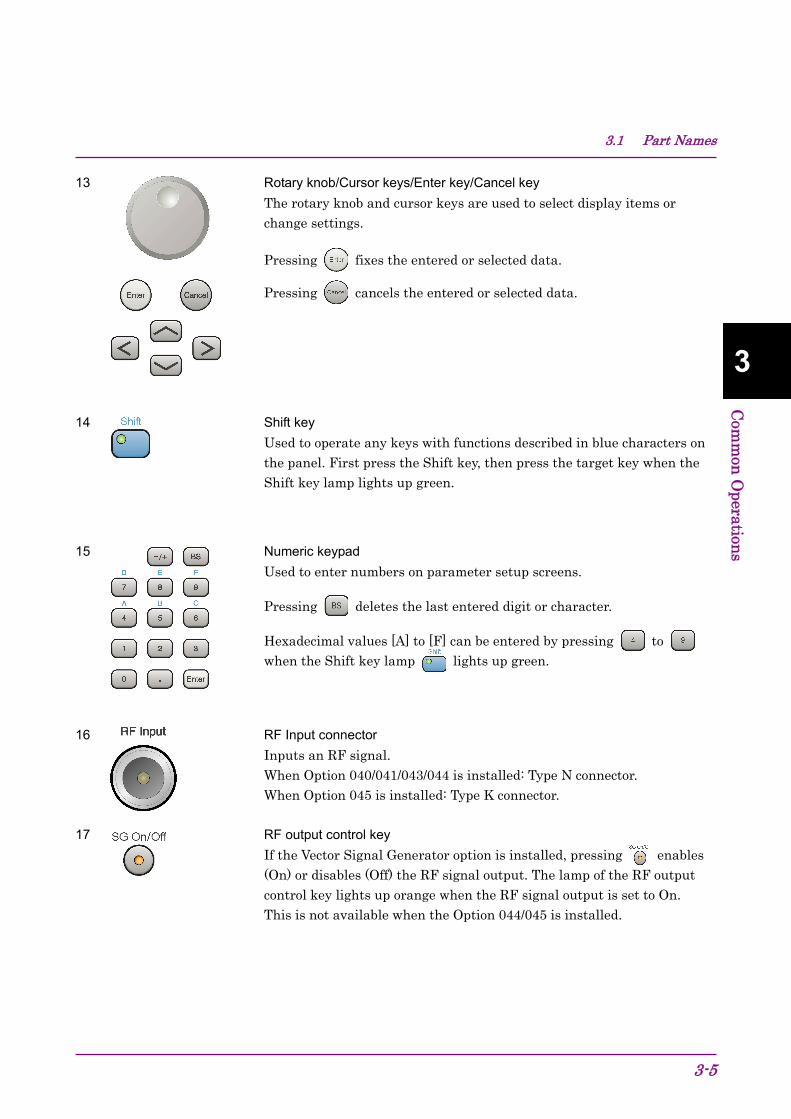
3.1 Part Names
3-5
3
Com
mon
Operation
s
13 Rotary knob/Cursor keys/Enter key/Cancel key The rotary knob and cursor keys are used to select display items or change settings.
Pressing fixes the entered or selected data.
Pressing cancels the entered or selected data.
14 Shift key Used to operate any keys with functions described in blue characters on the panel. First press the Shift key, then press the target key when the Shift key lamp lights up green.
15 Numeric keypad Used to enter numbers on parameter setup screens.
Pressing deletes the last entered digit or character.
Hexadecimal values [A] to [F] can be entered by pressing to when the Shift key lamp lights up green.
16 RF Input connector Inputs an RF signal. When Option 040/041/043/044 is installed: Type N connector. When Option 045 is installed: Type K connector.
17 RF output control key If the Vector Signal Generator option is installed, pressing enables (On) or disables (Off) the RF signal output. The lamp of the RF output control key lights up orange when the RF signal output is set to On. This is not available when the Option 044/045 is installed.

Chapter 3 Common Operations
3-6
18 RF output connector Outputs an RF signal, when the vector signal generator option is installed. This is not available when the Option 044/045 is installed.
19 USB connector (type A) Used to connect a USB keyboard or mouse or the USB flash drive supplied with the MS2830A.
20 Modulation control key When the vector signal generator option is installed, RF signal modulation can be turned on and off by pressing . When modulation is on, the key lamp lights up green. This is not available when the Option 044/045 is installed.
21 Application key Press to switch between applications.
SPA key Press to display the Spectrum Analyzer main screen.
SA key Press to display the Signal Analyzer main screen, when Option 005/105/006/106/007/009/109/077/177/078/178 is installed.
SG key Press to display the Signal Analyzer main screen, when Vector Signal Generator option is installed.
Blank key Not used.
Appli key When Auto is specified, the application selected by using the Application Switch is displayed. When Manual is specified, the pre-specified Application is displayed. Refer to 3.5.4 “Changing application layout”.

3.1 Part Names
3-7
3
Com
mon
Operation
s
22 1st Local Output connector This is available when the Option 044/045 is installed. Supplies local signal and bias current to the external mixer, and receives the IF signal with its frequency converted.

Chapter 3 Common Operations
3-8
Rear panel This section describes the connectors located on the rear panel.
Figure 3.1.1-2 Rear panel
1 Ref Input connector (reference frequency signal input connector) Inputs an external reference frequency signal (5 MHz/10 MHz/13 MHz). It is used for inputting reference frequency signals with accuracy higher than that of those inside the MS2830A, or for synchronizing the frequency of the MS2830A to that of other device.
2 Buffer Out connector (reference frequency signal output connector)
Outputs the reference frequency signal (10 MHz) generated inside the MS2830A. It is used for synchronizing the frequencies between other devices and the MS2830A based on the reference frequency signal output from this connector.
4 Sweep Status Out connector Outputs a signal that is enabled when an internal measurement is performed or measurement data is obtained.
12
11981067144 13 2 1 16 1517

3.1 Part Names
3-9
3
Com
mon
Operation
s
6 AUX connector This is a complex connector for inputting a baseband clock reference signal of the Vector Signal Generator (optional), and BER Measurement function (optional). See Table 3.1.1-1 for the internal pin assignment of the AUX connector.
Table 3.1.1-1 Pin assignment of AUX connector
Function Pin Number Signal Name
BER
24 BER_CLK 25 GND 48 BER_EN 45 GND 49 BER_DATA 50 GND
SG
13 MARKER1 11 GND 38 MARKER2 36 GND 39 MARKER3 16 GND 42 PULS_MOD 41 GND 22 BB_REF_CLK 20 GND
Do not connect anything to connectors not listed in Table 3.1.1-1, because they are interface connectors provided for device maintenance.
7 GPIB connector
Used when controlling the MS2830A externally via GPIB.
8 USB connector (type B) Used when controlling the MS2830A externally via USB.
9 Ethernet connector Used for connecting to a personal computer (PC) or for Ethernet connection.
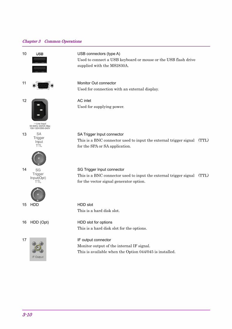
Chapter 3 Common Operations
3-10
10 USB connectors (type A) Used to connect a USB keyboard or mouse or the USB flash drive supplied with the MS2830A.
11 Monitor Out connector Used for connection with an external display.
12 AC inlet Used for supplying power.
13 SA Trigger Input connector This is a BNC connector used to input the external trigger signal (TTL) for the SPA or SA application.
14 SG Trigger Input connector This is a BNC connector used to input the external trigger signal (TTL) for the vector signal generator option.
15 HDD HDD slot This is a hard disk slot.
16 HDD (Opt) HDD slot for options This is a hard disk slot for the options.
17 IF output connector Monitor output of the internal IF signal.
This is available when the Option 044/045 is installed.
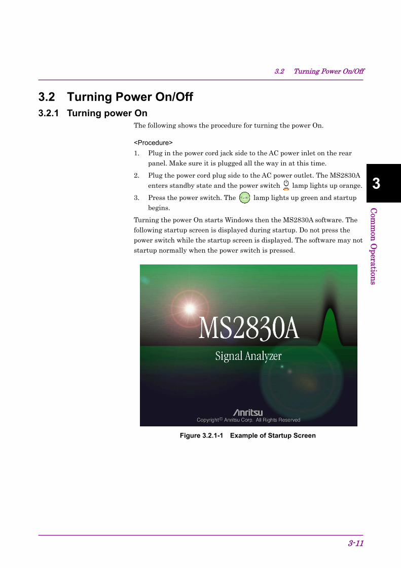
3.2 Turning Power On/Off
3-11
3
Com
mon
Operation
s
3.2 Turning Power On/Off 3.2.1 Turning power On
The following shows the procedure for turning the power On.
<Procedure> 1. Plug in the power cord jack side to the AC power inlet on the rear
panel. Make sure it is plugged all the way in at this time.
2. Plug the power cord plug side to the AC power outlet. The MS2830A enters standby state and the power switch lamp lights up orange.
3. Press the power switch. The lamp lights up green and startup begins.
Turning the power On starts Windows then the MS2830A software. The following startup screen is displayed during startup. Do not press the power switch while the startup screen is displayed. The software may not startup normally when the power switch is pressed.
Figure 3.2.1-1 Example of Startup Screen

Chapter 3 Common Operations
3-12
3.2.2 Turning power Off The following shows the procedure for turning the power Off.
When turning power Off using panel keys <Procedure> • Press the power switch to close applications and start shutdown.
The green power switch power lamp lights off, the lamp lights up orange, and the power is turned Off. The main power is On at this time.
Note:
Do not press the power switch for more than 4 seconds. Doing so will forcibly shut down the system during software closing processing.
When turning power Off using mouse connected to MS2830A <Procedure> Other than Windows 10
1. Connect the supplied mouse to the MS2830A and open the Start Menu from the Windows Taskbar. Refer to 5.1.1 “Displaying Windows Desktop”.
2. Select Turn off computer.
3. Select Turn off.
4. Shutdown begins, the green power switch power lamp lights off, the lamp lights up orange, and the power is turned Off. The main
power is On at this time.
Windows 10
1. Connect the supplied mouse to the MS2830A and open the Start Menu from the Windows Taskbar. Refer to 5.1.1 “Displaying Windows Desktop”.
2. Select Power.
3. Select Shut down.
4. Shutdown begins, the green power switch power lamp lights off, the lamp lights up orange, and the power is turned Off. The main
power is On at this time.
3.2 Turning Power On/Off
3-13
3
Com
mon
Operation
s
Forced shutdown <Procedure> • Press the power switch for four seconds or more. The green power
switch power lamp lights off, the lamp lights up orange, and the power is turned Off.
Notes:
Use forced shutdown as an emergency operation only when key, mouse, or keyboard operations are disabled. A failure may have occurred in the event the power cannot be turned Off even after pressing the power switch for 4 or more seconds. Unplug the power cord from the outlet and contact an Anritsu Service and Sales office or agent.
Unplugging the power plug while accessing the hard disk may result in hard disk failures. Unplug the power plug when the power is turned Off.

Chapter 3 Common Operations
3-14
3.3 Auto Calibration An auto calibration function that uses an internal calibrating oscillator is provided to minimize measurement errors of the MS2830A.
CAUTION Do not input signals to RF input when calibrating. Correct
calibration values cannot be obtained when the auto calibrating function is executed while signals are being input.
Do not turn off the power while executing the auto calibration because it will cause a malfunction or a failure.
Press (Cal) to display the Cal function menu.
Figure 3.3-1 Cal key
Table 3.3-1 Cal function menu
Function Key
Menu Display Function
F1 SIGANA All Executes all calibrations (Level Cal, Band Cal, Local Leak Suppression, Extra Band Cal) except Extra Band Cal.
F2 Level Cal Executes level calibration. F3 Band Cal Executes analysis band calibration.
F4 Local Leak Suppression Executes local leak suppression.
F6 Extra Band Cal Executes band calibration within the current frequency.
F7 Extra Band Cal Clear Clears the calibration values obtained by Extra Band Cal to zero.
F8 Close Returns to the application screen.
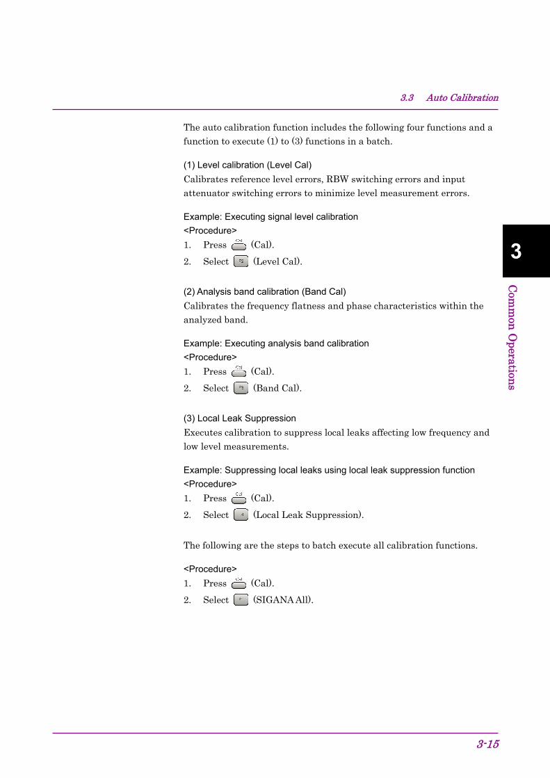
3.3 Auto Calibration
3-15
3
Com
mon
Operation
s
The auto calibration function includes the following four functions and a function to execute (1) to (3) functions in a batch.
(1) Level calibration (Level Cal) Calibrates reference level errors, RBW switching errors and input attenuator switching errors to minimize level measurement errors.
Example: Executing signal level calibration <Procedure> 1. Press (Cal).
2. Select (Level Cal).
(2) Analysis band calibration (Band Cal) Calibrates the frequency flatness and phase characteristics within the analyzed band.
Example: Executing analysis band calibration <Procedure> 1. Press (Cal).
2. Select (Band Cal).
(3) Local Leak Suppression Executes calibration to suppress local leaks affecting low frequency and low level measurements.
Example: Suppressing local leaks using local leak suppression function <Procedure> 1. Press (Cal).
2. Select (Local Leak Suppression).
The following are the steps to batch execute all calibration functions.
<Procedure> 1. Press (Cal).
2. Select (SIGANA All).

Chapter 3 Common Operations
3-16
(4) Extra Band Cal
Executes band calibration within the current frequency.
Example: Executes band calibration within the current frequency. <Procedure> 1. Press (Cal).
2. Select (Extra Band Cal).
The calibration value is applied if both of the following conditions are met:
• The difference between “the center frequency at the time of executing Extra Band Cal” and “the set value for the current center frequency” is 100 kHz or less.
• Both of the center frequencies are on the same frequency band.
This function cannot be executed when Spectrum Analyzer is selected. To activate Extra Band Cal, select any function other than Spectrum Analyzer, Signal Generator, BER Measurement, and Power Meter when Spectrum Analyzer is selected.
Extra Band Cal calibration values cannot be applied when Low Phase Noise is enabled. For Low Phase Noise, refer to 3.4.4 “System Settings”.
Depending on the version of the software you install, the existing Extra Band Cal calibration values might be cleared when installing the software. When the software is installed successfully, retry to execute Extra Band Cal and obtain a calibration value. For how to install the software, refer to 3.8.1 “Installing software or licenses”.
(5) Extra Band Cal Clear
Clears the calibration values obtained by Extra Band Cal.
Example: Clearing the calibration values obtained by Extra Band Cal. <Procedure>
1. Press (Cal)
2. Select (Extra Band Cal).
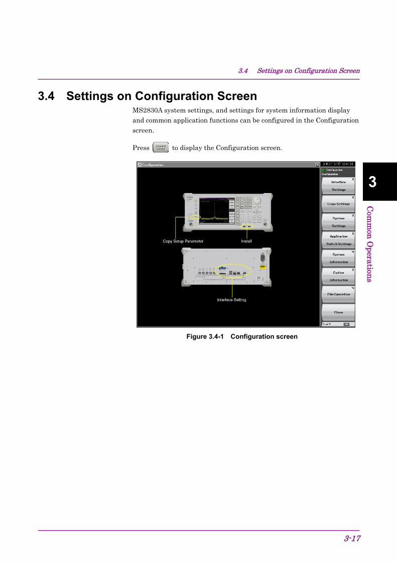
3.4 Settings on Configuration Screen
3-17
3
Com
mon
Operation
s
3.4 Settings on Configuration Screen MS2830A system settings, and settings for system information display and common application functions can be configured in the Configuration screen.
Press to display the Configuration screen.
Figure 3.4-1 Configuration screen
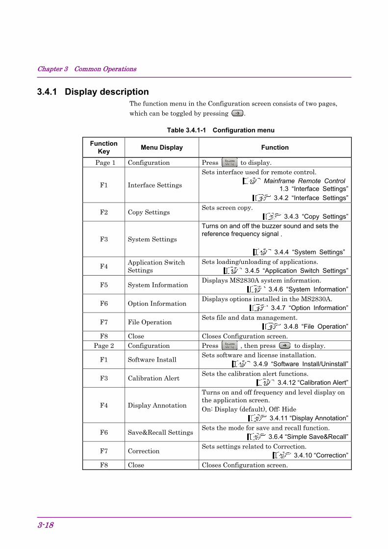
Chapter 3 Common Operations
3-18
3.4.1 Display description The function menu in the Configuration screen consists of two pages, which can be toggled by pressing .
Table 3.4.1-1 Configuration menu
Function Key
Menu Display Function
Page 1 Configuration Press to display.
F1 Interface Settings
Sets interface used for remote control. Mainframe Remote Control
1.3 “Interface Settings” 3.4.2 “Interface Settings”
F2 Copy Settings Sets screen copy.
3.4.3 “Copy Settings”
F3 System Settings
Turns on and off the buzzer sound and sets the reference frequency signal .
3.4.4 “System Settings”
F4 Application Switch Settings
Sets loading/unloading of applications. 3.4.5 “Application Switch Settings”
F5 System Information Displays MS2830A system information.
3.4.6 “System Information”
F6 Option Information Displays options installed in the MS2830A.
3.4.7 “Option Information”
F7 File Operation Sets file and data management.
3.4.8 “File Operation”F8 Close Closes Configuration screen.
Page 2 Configuration Press , then press to display.
F1 Software Install Sets software and license installation.
3.4.9 “Software Install/Uninstall”
F3 Calibration Alert Sets the calibration alert functions.
3.4.12 “Calibration Alert”
F4 Display Annotation
Turns on and off frequency and level display on the application screen. On: Display (default), Off: Hide
3.4.11 “Display Annotation”
F6 Save&Recall SettingsSets the mode for save and recall function.
3.6.4 “Simple Save&Recall”
F7 Correction Sets settings related to Correction.
3.4.10 “Correction”F8 Close Closes Configuration screen.

3.4 Settings on Configuration Screen
3-19
3
Com
mon
Operation
s
3.4.2 Interface Settings Pressing (Interface Settings) after displays the Interface Settings screen. GPIB, Ethernet and USB interface conditions used for remote control can be set in this screen. Select the item to be set with the cursor, and then press (Set) to reflect the settings of that item.
Refer to Section 1.3 “Interface Settings” in the MS2690A/MS2691A/MS2692A and MS2830A/MS2840A/MS2850A Signal Analyzer Operation Manual (Mainframe Remote Control) for details.
Figure 3.4.2-1 Interface Settings screen

Chapter 3 Common Operations
3-20
3.4.3 Copy Settings Pressing (Copy Settings) after displays the Copy Settings screen. Screen copy conditions can be set in this screen. Select the item to be set with the cursor, and then press (Set) to reflect the settings of that item.
Figure 3.4.3-1 Copy Settings screen
Table 3.4.3-1 Copy Settings items
Item Description
File Type Settings Selects the file format. BMP or PNG can be set.
Color Settings
Sets the screen copy color. Normal (same as screen display), Reverse, Monochrome, or Reversed monochrome can be selected.
File Name Settings
The file naming method can be selected from auto (date + sequence number) or random. This setting is applied also to determining name for parameters and waveform data saving file.
3.6.1 “Saving parameters and waveform data”
Storage Place Settings The file save location can be selected
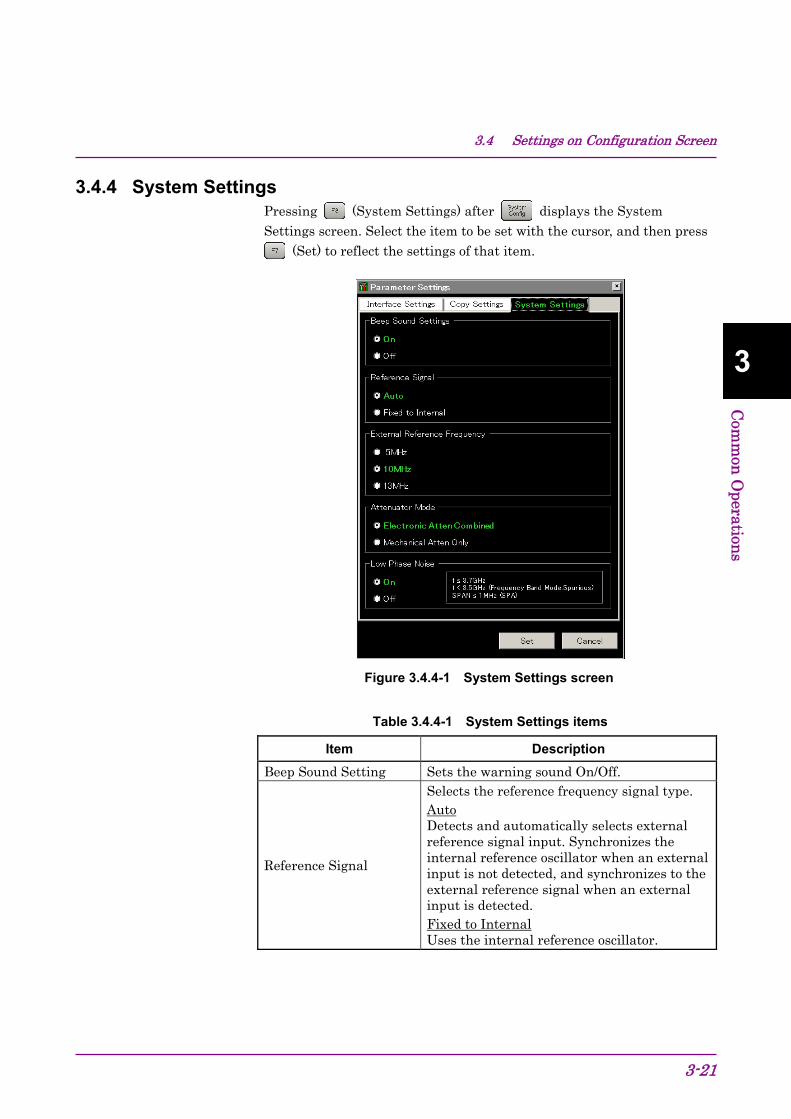
3.4 Settings on Configuration Screen
3-21
3
Com
mon
Operation
s
3.4.4 System Settings Pressing (System Settings) after displays the System Settings screen. Select the item to be set with the cursor, and then press
(Set) to reflect the settings of that item.
Figure 3.4.4-1 System Settings screen
Table 3.4.4-1 System Settings items
Item Description
Beep Sound Setting Sets the warning sound On/Off.
Reference Signal
Selects the reference frequency signal type. Auto Detects and automatically selects external reference signal input. Synchronizes the internal reference oscillator when an external input is not detected, and synchronizes to the external reference signal when an external input is detected. Fixed to Internal Uses the internal reference oscillator.

Chapter 3 Common Operations
3-22
Table 3.4.4-1 System Settings items (Cont’d)
Item Description
External Reference Frequency
Selects signal frequency, when using external reference signal as the signal source for reference frequency.
Attenuator Mode*1
Switches between Electronic attenuator (E-ATT) and Mechanical attenuator (M-ATT). *2
Electronic Atten Combined : Mostly uses E-ATT with partial use of M-ATT.
Mechanical Atten Only : Exclusively uses M-ATT.
Low Phase Noise*3
Sets Low Phase Noise option On/Off (enable/disable). The setting range is displayed at the right side of the frame.
*1: This is displayed for MS2830A-040/041/043/044/045.
*2: The switching is made according to the table shown below.
*3: This is displayed when the MS2830A-062/066 Low Phase Noise Performance Option is installed. Figure 3.4.4-1 is an example for other than Option 040. For Option 040, the setting range display is only for SPAN ≤1 MHz (SPA).
3.4 Settings on Configuration Screen
3-23
3
Com
mon
Operation
s
Table 3.4.4-2 Attenuator Mode switching
Option Frequency*1 Electronic Atten
Combined Mechanical Atten Only
040 041 043 044
≤ 6 GHz 0 to 10 dB → M-ATT 12 to 40 dB → E-ATT 42 to 60 dB → M-ATT
All M-ATT
> 6 GHz All M-ATT All M-ATT 045 ≤ 6 GHz*2 0, 10 dB → M-ATT*4
12 to 40 dB → E-ATT 50, 60 dB → M-ATT
All M-ATT
> 6 GHz*3 All M-ATT All M-ATT
*1: The following reference frequency is used:
Spectrum analyzer mode: STOP frequency
Signal analyzer mode: Center frequency
*2: Spurious Mode: Stop frequency ≤ 4.1 GHz and Start frequency < 4 GHz
*3: Spurious Mode: Stop frequency > 4.1 GHz or Start frequency ≥ 4 GHz
*4: Attenuator for 040/041/043/044 uses 2 dB step for both M-ATT and E-ATT Attenuator for 045 uses 10 dB step for M-ATT and 2 dB step for E-ATT.

Chapter 3 Common Operations
3-24
3.4.5 Application Switch Settings Pressing (Application Switch Settings) after displays the Application Switch Settings function menu. The loading/unloading of applications can be set from this menu. Select the item to be set with the cursor, and then press (Set) to display the setting window of that item or start performing the setting.
Table 3.4.5-1 Application Switch Settings items
Function Key
Menu Display Function
F1 Load Application Select
Selects an application located in the Unloaded Applications frame to startup the selected application.
3.5.1 “Loading applications”
F2 Unload Application Select
Selects an application located in the Loaded Applications frame to end the selected application.
3.5.2 “Unloading applications”
F3 Position Change Sets the loaded application anywhere on the Application Switch menu.
3.5.4 “Changing application layout”
F7 Set Displays the setting window for the items selected by pressing F1, F2, or F3, or starts performing the setting.
F8 Close Returns to the Configuration screen.
3.4 Settings on Configuration Screen
3-25
3
Com
mon
Operation
s
3.4.6 System Information Pressing (System Information) after displays the System Information menu. The MS2830A system information can be viewed from this menu. Pressing the function key corresponding to the system information to be viewed displays the window of the selected item.
Table 3.4.6-1 System Information setting items
Function Key
Menu Display Function
Page 1 System Information Press and then press (System Information) to display.
F1 System Information View
Displays the MS2830A product type, serial number, operating time, and attenuator switching counts. ATT01: 2 dB (With MS2830A-045: No display) ATT02: 4 dB (With MS2830A-045: No display) ATT03: 8 dB (With MS2830A-045: No display) ATT04: 10 dB ATT05: 16 dB (With MS2830A-045: 30 dB) ATT06: 20 dB
F2 Software Version View
Displays the version of the software installed in the MS2830A.
F3 FPGA Version View Displays the FPGA version for each board installed in the MS2830A.
F4 Board Revision View Displays the revisions of each board installed in the MS2830A. (Some boards are not displayed.)
F5 Software License View
Displays the license of software installed in the MS2830A.
F6 SG Wave License View
Displays the license of SG waveforms installed in the MS2830A (only when a vector signal generator is installed).
Page 2 System Information Press , and then press (System Information) to display.
F1 System Reset Initializes the system. F7 Information Save Saves the MS2830A system information.
Chapter 3 Common Operations
3-26
3.4.7 Option Information Pressing (Option Information) after displays the option screen. Information on options installed in the MS2830A can be viewed in this screen.
3.4.8 File Operation Pressing (File Operation) after displays the File Operation function menu. Data files can be managed from this menu. Pressing the function key corresponding to the data file to be managed displays the setting window of that item.
Table 3.4.8-1 Description of File Operation setting items
Function Key
Menu Display Function
F1 Device (D:) Selects drive.
F2 Parameter Save Data Manages save data for parameter settings file.
F3 Copy Data Manages copied file data. F4 Trace Data Manages trace data. F5 Digitizer Data Manages digitized data. F7 System Information Manages system information.

3.4 Settings on Configuration Screen
3-27
3
Com
mon
Operation
s
3.4.9 Software Install/Uninstall Press , and then press to move to page 2 of the Configuration function menu. Press (Software Install) to display the Software Install menu. Software can be installed and uninstalled to/from the MS2830A from this menu. Pressing the function key corresponding to the item to be set executes the selected item. Refer to Section 3.8 “Installing and Uninstalling” for details.
3.4.10 Correction When making measurements with a spectrum analyzer, it may be necessary to correct the error and gain of the measurement system. The following are examples of them:
• Frequency characteristics and loss of measurement cables • Frequency characteristics and loss of pre-amplifier, etc. connected to
RF input connector. • When wanting to measure the field strength with an antenna or
near-field probe connected (antenna factor correction).
In the cases above, Correction functions allow you to correct the error and gain.
You can input correction value via csv file or remote control operation. If inputting via csv file, refer to the Recall Correction Table. For details of remote command input, see “Correction Make Up” in Chapter 4 of the MS2690A/MS2691A/MS2692A and MS2830A/MS2840A/MS2850A Signal Analyzer Operation Manual (Mainframe Remote Control).
Chapter 3 Common Operations
3-28
Correction
Press , and then press to move to page 2 of the Configuration function menu. Press (Correction) to display the Correction function menu. Those functions are used to set correction factors for frequency characteristics.
Table 3.4.10-1 Correction function menu
Function Key
Menu Display Function
F1 Correction (On/Off) Sets Correction to On/Off. When set to On, the level correction processing function is executed.
F2 Save Correction Table Opens the Save Correction Table function menu.
F3 Recall Correction Table Opens the Recall Correction Table function menu.
F8 Close Returns to the Configuration menu.
Save Correction Table
Pressing (Save Correction Table) on Correction function menu displays Save Correction Table function menu. Those functions are used to save level frequency characteristics.
Table 3.4.10-2 Save Correction Table function menu
Function Key
Menu Display Function
F1 Device (D:) Selects the drive.
F7 Save Correction Table
Saves the level frequency characteristics. When File Name Setting is set to Data + sequential, the file is automatically named ”Corr date_sequential number”. The file is in CSV format and is saved in “[Selected drive]:\Anritsu Corporation\Signal Analyzer\User Data\Corrections\”. Up to 1000 files can be saved in the folder.
F8 Close Returns to the Configuration menu.

3.4 Settings on Configuration Screen
3-29
3
Com
mon
Operation
s
Recall Correction Table
Pressing (Recall Correction Table) on Correction function menu displays the Recall Correction Table function menu. Those functions are used to recall the saved level frequency characteristics.
Table 3.4.10-3 Recall Correction Table function menu
Function Key
Menu Display Function
F1 Device (D:) Selects the drive.
F7 Recall Correction Table
Recalls the level frequency characteristics. A file is in CSV format.
F8 Close Returns to the Configuration menu.
A Correction file is in CSV format, as shown below. Signal levels can be corrected by sets of frequency and level in the Correction file. Also, the correction factors between Fa and Fb are calculated by the linear interpolation of log value at Fa and Fb.
Frequency(Hz),Level(dB) 0,0 980000000,1 1000000000,4 1200000000,1
Describe the frequency and level to be corrected within the following range for the CSV file.
Up to 4096 items of correction data can be set.
[Frequency] Range –1 to 400 GHz Resolution 1 Hz Set the unit in Hz.
[Level] Range –100 to 100 dB Resolution 0.001 dB

Chapter 3 Common Operations
3-30
As shown in Figure 3.4.10-1, if the frequency range over which the correction factors are entered is from Fa to Fb, displayed frequency ranges lower than Fa or higher than Fb have correction factors applied. The correction factor for frequencies lower than Fa is the same as that (La) for Fa and the correction factor for frequencies higher than Fb is the same as that (Lb) for Fb. The correction factors between Fa and Fb are calculated by the linear interpolation of log value at Fa and Fb.
Figure 3.4.10-1 Operation When Correction Factors Are Entered
Correction factors apply to all the applications other than Signal Generator.
In Signal Analyzer functions, the correction factors of the center frequency are applied to all the trace data in the same span.
Executing the following functions initializes the correction factors. Installing application software does not initialize the correction factors.
• To execute System Reset. • To execute the system recovery functions.
Fa Fb Frequency (Hz)
Level (dBm)
Correction Factor Input Range
La
Lb

3.4 Settings on Configuration Screen
3-31
3
Com
mon
Operation
s
3.4.11 Display Annotation When Display Annotation is OFF, the measurement target’s frequency and level included in the frequency-related settings, level-related settings, marker values, and measurement results are hidden from the application screen to avoid being seen.
Press and then press . Switch On/Off the display by pressing (Display Annotation) on Page 2 of the Configuration function menu.
On Displays frequency and signal level. (Default) Off Hides frequency and signal level.
Note:
When Display Annotation is Off, only applications that support Display Annotation function are displayed in the Application Switch menu.

Chapter 3 Common Operations
3-32
3.4.12 Calibration Alert Calibration Alert displays an alert when the temperature change or the elapsed time based on the last automatic calibration (SIGANA All) meets the trigger conditions. The trigger conditions for alerts, or temperature thresholds and elapsed time, can be specified.
Press and then press . Pressing (Calibration Alert) on Page 2 of the Configuration function menu displays the Calibration Alert function menu.
Table 3.4.12-1 Calibration Alert function menu
Function Key
Item Description
F1 Alert Mode
Specifies the trigger conditions for alerts. None No alert occurs. Temperature An alert occurs when a temperature goes outsides the specified thresholds based on the internal temperature measured at the last automatic calibration (SIGANA All). Elapsed Time An alert occurs when the time passes longer than the specified Elapsed Time since the last automatic calibration time (SIGANA All) Both An alert occurs when either of temperature change or elapsed time meets the trigger conditions.
F2 Temperature
Specifies the temperature thresholds for alerts. Range 0.5 to 50.0°C Resolution 0.5°C Default 2.0°C
F3 Elapsed Time
Specifies the elapsed time for alerts. Range 1 to 200 h (hours) Resolution 1 h (hour) Default 1 h (hour)
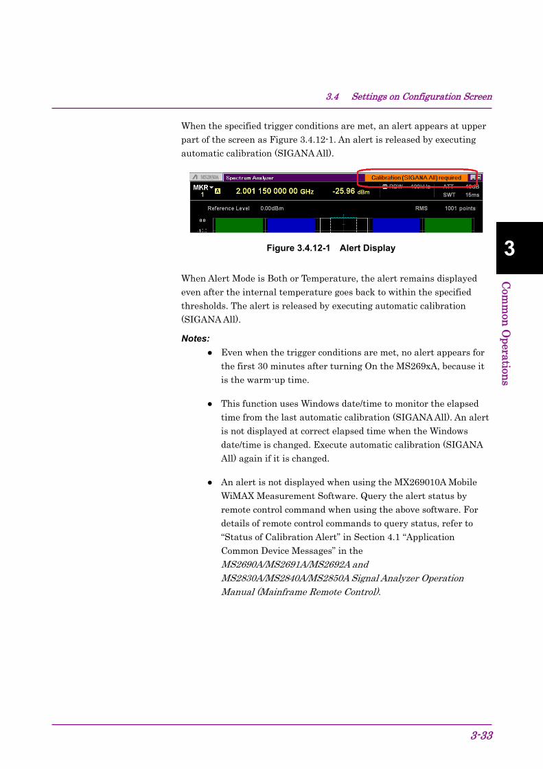
3.4 Settings on Configuration Screen
3-33
3
Com
mon
Operation
s
When the specified trigger conditions are met, an alert appears at upper part of the screen as Figure 3.4.12-1. An alert is released by executing automatic calibration (SIGANA All).
Figure 3.4.12-1 Alert Display
When Alert Mode is Both or Temperature, the alert remains displayed even after the internal temperature goes back to within the specified thresholds. The alert is released by executing automatic calibration (SIGANA All).
Notes:
Even when the trigger conditions are met, no alert appears for the first 30 minutes after turning On the MS269xA, because it is the warm-up time.
This function uses Windows date/time to monitor the elapsed time from the last automatic calibration (SIGANA All). An alert is not displayed at correct elapsed time when the Windows date/time is changed. Execute automatic calibration (SIGANA All) again if it is changed.
An alert is not displayed when using the MX269010A Mobile WiMAX Measurement Software. Query the alert status by remote control command when using the above software. For details of remote control commands to query status, refer to “Status of Calibration Alert” in Section 4.1 “Application Common Device Messages” in the MS2690A/MS2691A/MS2692A and MS2830A/MS2840A/MS2850A Signal Analyzer Operation Manual (Mainframe Remote Control).
Chapter 3 Common Operations
3-34
3.5 Loading, Unloading, and Switching Applications The following describes the procedures for loading, unloading and switching applications (signal analyzer, spectrum analyzer, etc.).
Loading applications refers to the setting of applications already installed to an execution state. Loaded applications are registered to the Application Switch menu and are in an operable state. In addition, these applications enter an execution state when the power is turned on after registration. At the factory default, all applications are installed thus in “loaded” state. However, application in excess of maximum number of loadable applications is listed as “Unloaded”.
Unloading applications refers to the halting and ending of applications in an execution state. Unloaded applications are released from Application Switch menu registration and will not run until they are re-loaded.
Switching applications refers to the operation for selecting the applications to be operated from the applications in an execution state. You can select the target applications from the Application Switch menu.
CAUTION
Applications registered to the Application Switch menu
automatically enter an execution state when starting up
the MS2830A. The more registered applications, the
longer startup will take.
In the event running applications are suddenly ended
while operating Windows, press , turn the MS2830A
power Off or shutdown Windows, and then turn the
MS2830A power On again.
When many applications are running simultaneously
and the measurement software calls a measurement
function from the signal or spectrum analyzer functions,
sometimes the application may take a long time to
switch. Reducing the number of simultaneously
running applications by unloading them will help
prevent this problem.

3.5 Loading, Unloading, and Switching Applications
3-35
3
Com
mon
Operation
s
3.5.1 Loading applications Applications can be loaded from the Configuration screen.
<Procedure> 1. After pressing , press (Application Switch Settings) to
display the Application Switch Registration screen.
2. Press (Load Application Select), select the applications to be loaded from the applications displayed in “Unloaded Applications” at the bottom part of the screen, and then press (Set). Press (Load Application Select) once again, when an error message “Loading application failed” is displayed.
Figure 3.5.1-1 Application Switch Registration screen
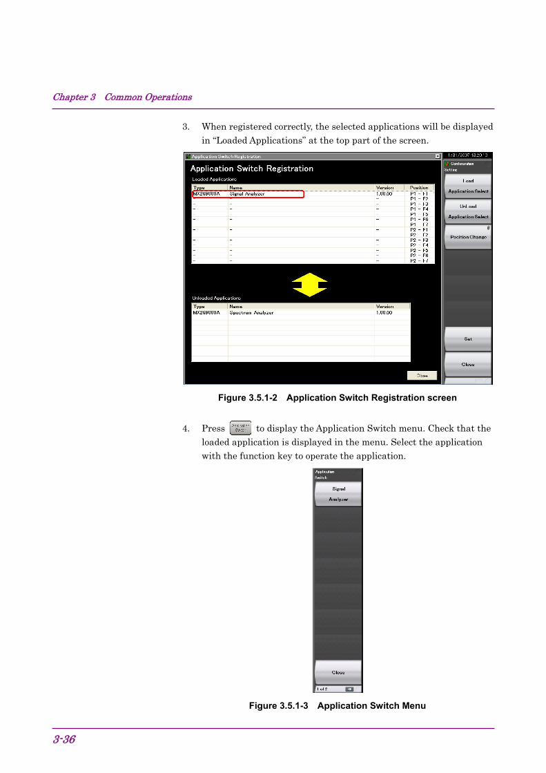
Chapter 3 Common Operations
3-36
3. When registered correctly, the selected applications will be displayed in “Loaded Applications” at the top part of the screen.
Figure 3.5.1-2 Application Switch Registration screen
4. Press to display the Application Switch menu. Check that the loaded application is displayed in the menu. Select the application with the function key to operate the application.
Figure 3.5.1-3 Application Switch Menu

3.5 Loading, Unloading, and Switching Applications
3-37
3
Com
mon
Operation
s
3.5.2 Unloading applications Applications can be unloaded from the Configuration screen.
<Procedure> 1. After pressing , press (Application Switch Settings) to
display the Application Switch Registration screen.
2. Press (Unload Application Select), select the application to be unloaded from the applications displayed in “Loaded Applications” at the top part of the screen with the cursor, and then press (Set).
Figure 3.5.2-1 Application Switch Registration screen

Chapter 3 Common Operations
3-38
3. When ended correctly, the selected applications will be displayed in “Unloaded Applications” at the bottom part of the screen.
Figure 3.5.2-2 Application Switch Settings screen

3.5 Loading, Unloading, and Switching Applications
3-39
3
Com
mon
Operation
s
3.5.3 Switching applications Applications to be operated can be switched in the Application Switch menu.
Pressing displays the Application Switch menu. Pressing the function key corresponding to the application switches to the selected application screen.
If the Application (Auto/Manual) setting is set to Auto as explained
in 3.5.4 “Changing application layout”, the application you selected above
is assigned. From the next time on, you can call up the application by
only pressing .
Note:
When Display Annotation is Off, only applications that support Display Annotation function are displayed in the Application Switch menu.
Figure 3.5.3-1 Application Switch menu

Chapter 3 Common Operations
3-40
3.5.4 Changing application layout The layout of applications can be changed as desired in the Application Switch menu. Set the application layout in the Configuration screen.
<Procedure> 1. After pressing , press (Application Switch Settings) to
display the Application Switch Registration screen.
2. Press (Position Change) to display the Application Switch Function Position Edit screen. The Setting function menu is also displayed.
Note:
The arrangement in the Function Position area is the arrangement of the function keys displayed according to the Application Switch key. The arrangement in the Application Key area is the same as the Application Key arrangement.
Table 3.5.4-1 Setting function menu description
Function Key
Menu Display Function
F1 Application (Auto/Manual)
Auto: The setting of Application Key slot 5 is performed automatically, and an application is assigned to the key automatically.
3.5.3 “Switching applications”Manual: The setting of Application Key slot 5 is performed manually, and the assignment of an application to the key is fixed.
F7 Set Finalizes the assignment of applications. F8 Cancel Returns to the Configuration screen.
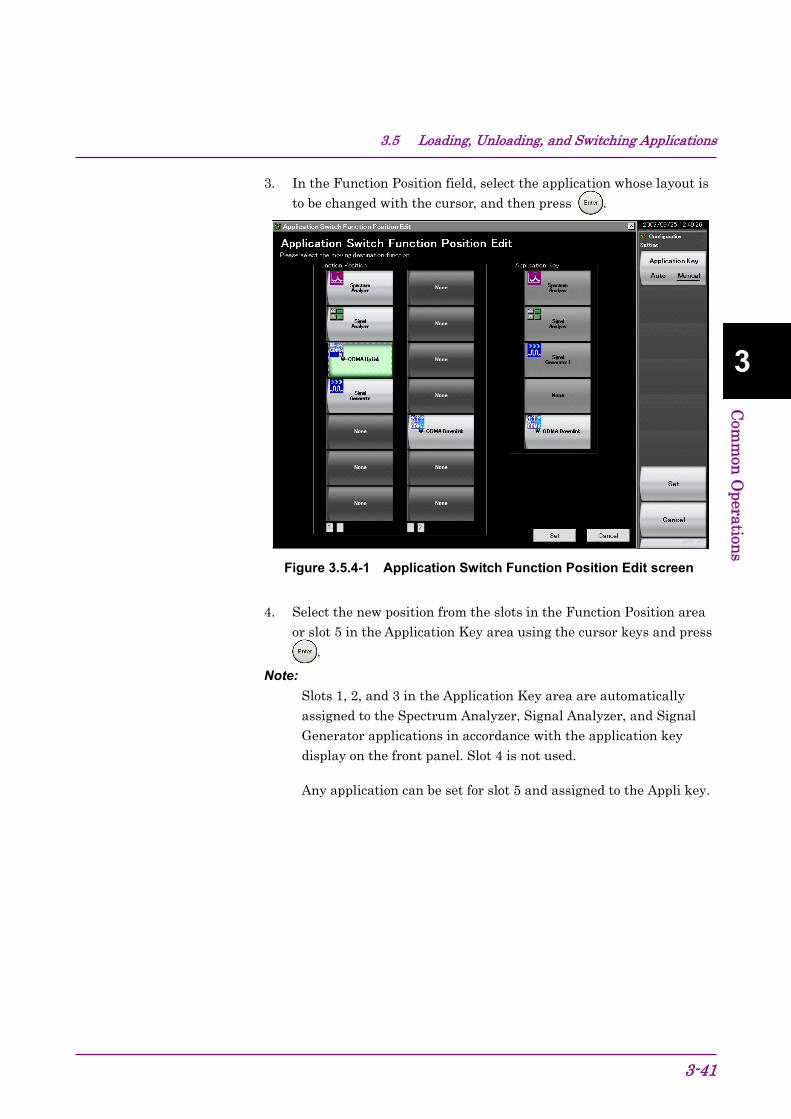
3.5 Loading, Unloading, and Switching Applications
3-41
3
Com
mon
Operation
s
3. In the Function Position field, select the application whose layout is to be changed with the cursor, and then press .
Figure 3.5.4-1 Application Switch Function Position Edit screen
4. Select the new position from the slots in the Function Position area or slot 5 in the Application Key area using the cursor keys and press
.
Note:
Slots 1, 2, and 3 in the Application Key area are automatically assigned to the Spectrum Analyzer, Signal Analyzer, and Signal Generator applications in accordance with the application key display on the front panel. Slot 4 is not used.
Any application can be set for slot 5 and assigned to the Appli key.
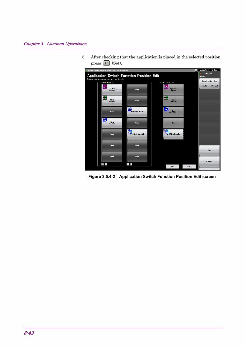
Chapter 3 Common Operations
3-42
5. After checking that the application is placed in the selected position, press (Set).
Figure 3.5.4-2 Application Switch Function Position Edit screen

3.6 Save and Recall Functions
3-43
3
Com
mon
Operation
s
3.6 Save and Recall Functions This section describes the conditions for setting parameters to the internal hard disk and USB flash drive (Parameter) and saving (Save) and recalling (Recall) of waveform data (Trace).
Note:
Use the USB flash drive supplied with the MS2830A. Using other USB flash drive may cause malfunction due to device incompatibility.
3.6.1 Saving parameters and waveform data With the MS2830A, the current setting conditions and waveform data can be saved to the internal hard disk or a USB flash drive.
Saving parameter settings <Procedure> 1. Press from the Configuration screen, Signal Analyzer screen,
or Spectrum Analyzer screen to display the Save function menu shown in Table 3.6.1-1.
2. Press (Device) to change the save destination. When the Setting window is displayed, select the drive to be saved and then press (Set) to set.
3. When the save destination has been determined, press (Save Application). The save target will be all parameter setting conditions (Parameter) of the launched applications.
The parameter saving file will be output with the name “Param_date_ sequential number.xml.” If a parameter is saved on the same date, the file is automatically named in the order “Param_date_000.xml,” “Param_date_001.xml,” “Param_date_002.xml” and so on. Parameter saves of up to “Param_date_999.xml” can be made.
A sequential number from 000 to 999 will be added to the file name.
To specify the file name, set User Specified Name in File Name Settings in Copy Settings. The parameter saving file name can be specified when saving.
3.4.3 “Copy Settings”
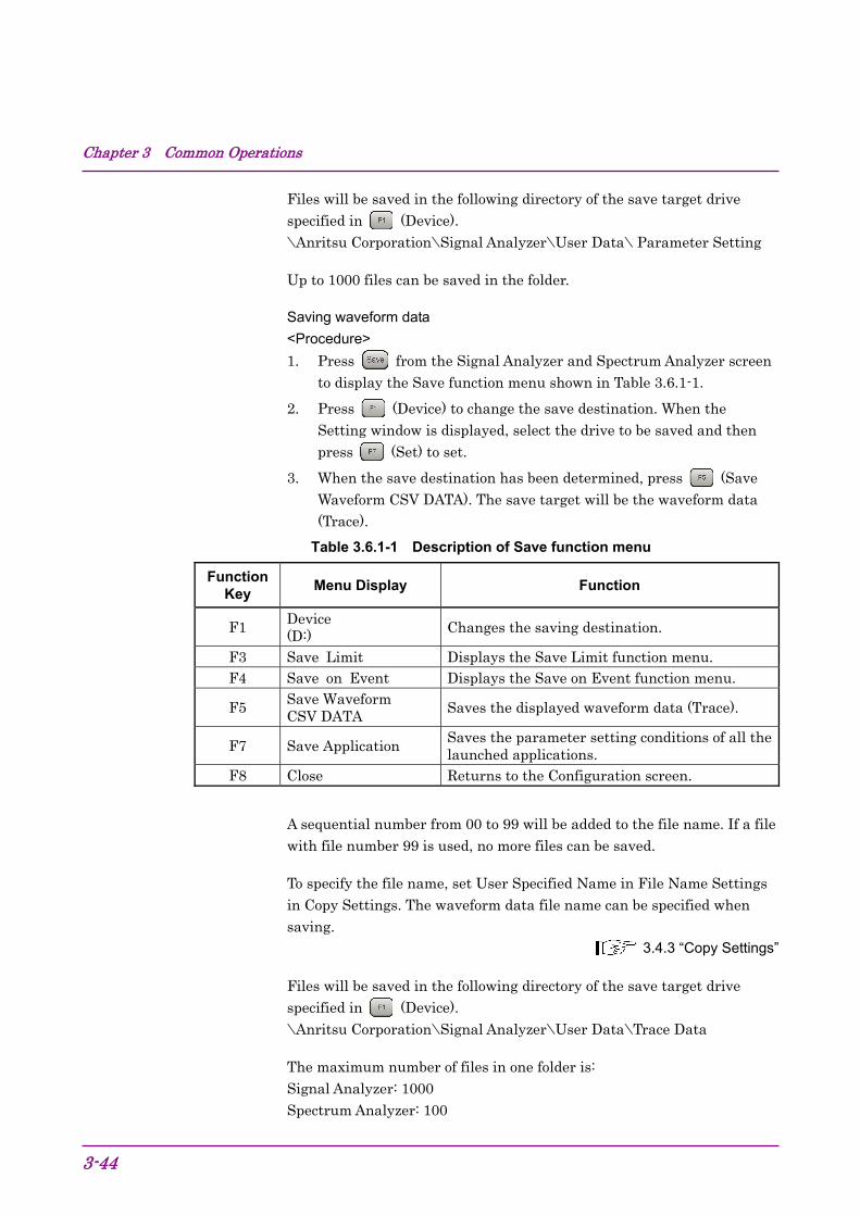
Chapter 3 Common Operations
3-44
Files will be saved in the following directory of the save target drive specified in (Device). \Anritsu Corporation\Signal Analyzer\User Data\ Parameter Setting
Up to 1000 files can be saved in the folder.
Saving waveform data <Procedure> 1. Press from the Signal Analyzer and Spectrum Analyzer screen
to display the Save function menu shown in Table 3.6.1-1.
2. Press (Device) to change the save destination. When the Setting window is displayed, select the drive to be saved and then press (Set) to set.
3. When the save destination has been determined, press (Save Waveform CSV DATA). The save target will be the waveform data (Trace).
Table 3.6.1-1 Description of Save function menu
Function Key
Menu Display Function
F1 Device (D:) Changes the saving destination.
F3 Save Limit Displays the Save Limit function menu. F4 Save on Event Displays the Save on Event function menu.
F5 Save Waveform CSV DATA Saves the displayed waveform data (Trace).
F7 Save Application Saves the parameter setting conditions of all the launched applications.
F8 Close Returns to the Configuration screen.
A sequential number from 00 to 99 will be added to the file name. If a file with file number 99 is used, no more files can be saved.
To specify the file name, set User Specified Name in File Name Settings in Copy Settings. The waveform data file name can be specified when saving.
3.4.3 “Copy Settings”
Files will be saved in the following directory of the save target drive specified in (Device). \Anritsu Corporation\Signal Analyzer\User Data\Trace Data
The maximum number of files in one folder is: Signal Analyzer: 1000 Spectrum Analyzer: 100

3.6 Save and Recall Functions
3-45
3
Com
mon
Operation
s
3.6.2 Recalling parameters With the MS2830A, settings can be restored by loading saved setting conditions from the internal hard disk or a USB flash drive.
Recalling parameter setting conditions only of applications to be operated using Application Switch <Procedure> 1. Press from the Configuration, Signal Analyzer, or Spectrum
Analyzer screen to display the Recall function menu shown in Table 3.6.2-1.
2. Press (Device) to change the location of saved parameter setting conditions. When the Setting window is displayed, select the drive in which parameter setting conditions are saved, and then press (Set) to set.
3. Press (Recall Current Application) to display the Parameter Save Data List.
4. Select the parameter setting conditions to be recalled with the cursor, and then press (Set) to recall parameter setting conditions to the application.

Chapter 3 Common Operations
3-46
Recalling parameter setting conditions for all launched applications. <Procedure> 1. Press from the Configuration, Signal Analyzer or Spectrum
Analyzer screen to display the Recall function menu shown in Table 3.6.2-1.
2. Press (Device) to change the location of saved setting parameters. When the Setting window is displayed, select the drive in which setting parameters are saved, and then press (Set) to set.
3. Press (Recall All Application) to display the Parameter Save Data List.
4. Select the parameter setting conditions to be recalled with the cursor, and then press (Set) to recall the parameter setting conditions to all loaded applications.
Table 3.6.2-1 Recall Menu Items
Function Key
Menu Display Function
F1 Device (D:) Changes the saving destination.
F6 Recall Current Application
Displays the Parameter Save Data List. This function is used to recall the parameter setting conditions of only the current application.
F7 Recall all ApplicationDisplays the Parameter Save Data List. This function is used to recall the parameter setting conditions of all the loaded applications.
F8 Close Returns to the Configuration screen.
3.6 Save and Recall Functions
3-47
3
Com
mon
Operation
s
3.6.3 Screen copy A displayed screen image can be saved to the internal hard disk or a USB flash drive as a BMP or PNG formatted file.
The conditions for copying a screen image can be set in the Copy Settings screen. Refer to the following section for details.
3.4.3 “Copy Settings” Executing screen copy <Procedure> 1. Display the screen to be saved.
2. Press to save the screen image to the selected media in BMP or PNG format. A saved file name is displayed when saving is completed.
The image file will be output with the file name “Copy_Date_Sequence_Number.bmp”. When screen copies are made on the same date, they are automatically named in an order as “Copy_Date_000.bmp”, “Copy_Date_001.bmp”, “Copy_Date_002.bmp”, and so on. Screen copies of up to “Copy_Date_999.bmp” can be made. A sequential number from 000 to 999 will be added to the file name.
Files will be saved in the following directory of the save target drive specified in (Device). \Anritsu Corporation\Signal Analyzer\User Data\Copy Files
Up to 1000 files can be saved in the folder.

Chapter 3 Common Operations
3-48
3.6.4 Simple Save&Recall This function allows parameter setting conditions to be recalled with little operations.
Enabling Simple Save&Recall
<Procedure> 1. Press to display the Configuration screen.
2. Press to display page 2 of the Configuration function menu.
3. Press (Save&Recall Settings) to display the Save&Recall Settings function menu in Figure 3.6.4-1.
Figure 3.6.4-1 Save&Recall Settings function menu
Table 3.6.4-1 Save&Recall Settings function menu
Menu Display Description
Save&Recall Mode
Switches the Save&Recall mode. Set the Standard mode or Simple mode.
3.6.1 “Saving parameters and waveform data”
3.6.2 “Recalling parameters”
Simple Save&Recall Name
Use this item to change the parameter name (file name) to be saved from the default setting in Simple mode.
F1
F2
F3
F4
F5
F6
F7
F8

3.6 Save and Recall Functions
3-49
3
Com
mon
Operation
s
Changing the parameter name (file name) to be saved from the default setting
Pressing (Simple Save&Recall Name) in Figure 3.6.4-1 displays the Simple Save&Recall Name function menu in Figure 3.6.4-2. Up to ten parameter names can be registered in Simple mode.
The default parameter names are PRM_1 to PRM_10. To change the parameter name, press the function key to be changed.
Figure 3.6.4-2 Simple Save&Recall Name function menu
F1
F2
F3
F4
F5
F6
F7
F8
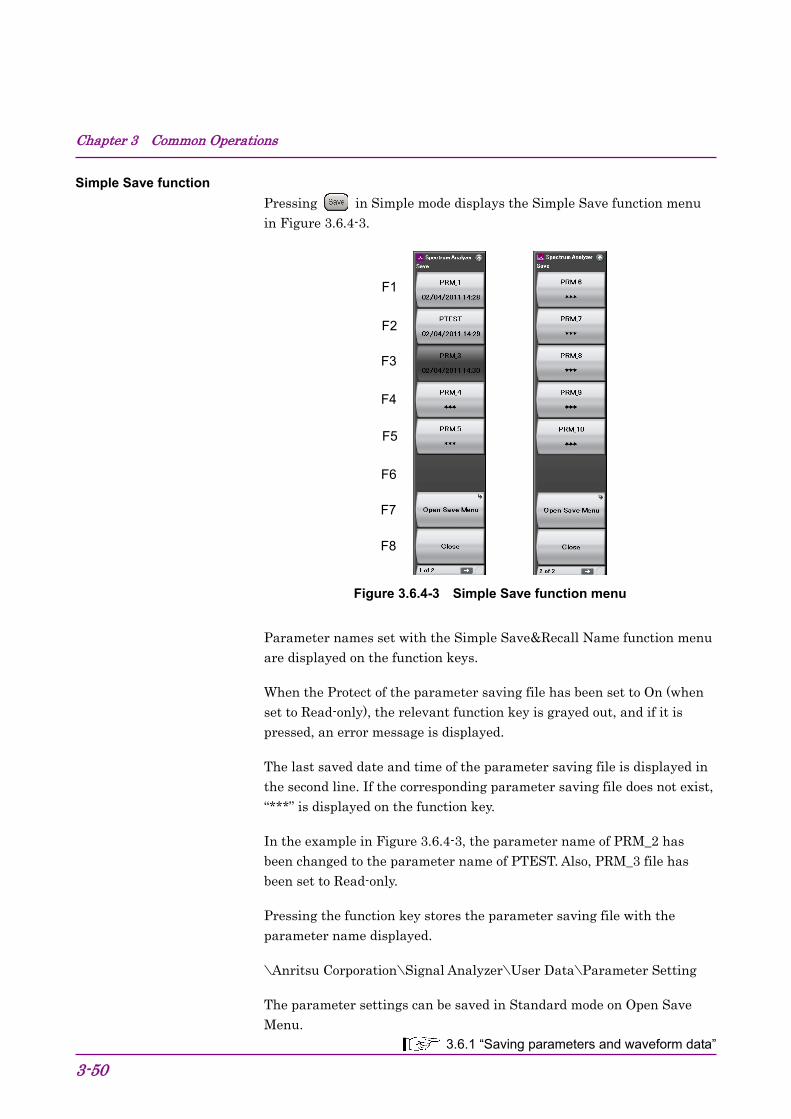
Chapter 3 Common Operations
3-50
Simple Save function
Pressing in Simple mode displays the Simple Save function menu in Figure 3.6.4-3.
Figure 3.6.4-3 Simple Save function menu
Parameter names set with the Simple Save&Recall Name function menu are displayed on the function keys.
When the Protect of the parameter saving file has been set to On (when set to Read-only), the relevant function key is grayed out, and if it is pressed, an error message is displayed.
The last saved date and time of the parameter saving file is displayed in the second line. If the corresponding parameter saving file does not exist, “***” is displayed on the function key.
In the example in Figure 3.6.4-3, the parameter name of PRM_2 has been changed to the parameter name of PTEST. Also, PRM_3 file has been set to Read-only.
Pressing the function key stores the parameter saving file with the parameter name displayed.
\Anritsu Corporation\Signal Analyzer\User Data\Parameter Setting
The parameter settings can be saved in Standard mode on Open Save Menu.
3.6.1 “Saving parameters and waveform data”
F1
F2
F3
F4
F5
F6
F7
F8
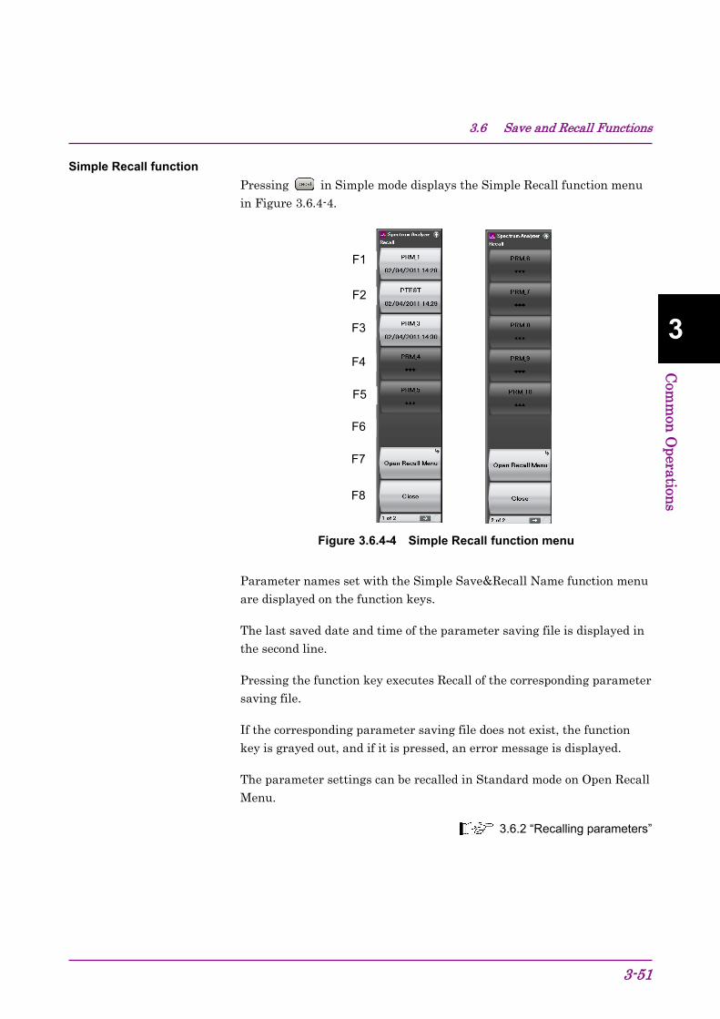
3.6 Save and Recall Functions
3-51
3
Com
mon
Operation
s
Simple Recall function
Pressing in Simple mode displays the Simple Recall function menu in Figure 3.6.4-4.
Figure 3.6.4-4 Simple Recall function menu
Parameter names set with the Simple Save&Recall Name function menu are displayed on the function keys.
The last saved date and time of the parameter saving file is displayed in the second line.
Pressing the function key executes Recall of the corresponding parameter saving file.
If the corresponding parameter saving file does not exist, the function key is grayed out, and if it is pressed, an error message is displayed.
The parameter settings can be recalled in Standard mode on Open Recall Menu.
3.6.2 “Recalling parameters”
F1
F2
F3
F4
F5
F6
F7
F8

Chapter 3 Common Operations
3-52
3.7 Initializing This section describes how to initialize settings.
3.7.1 Preset Preset is a function for initializing application settings. Configuration screen settings are not initialized using this function. Similarly, there is no effect on user data saved to the internal hard disk.
<Procedure> 1. Press to display the Preset function menu.
2. Press (Preset) to initialize only applications to be operated using the Application Switch.
3. Press (Preset All Application) to initialize all loaded applications.
Table 3.7.1-1 Preset function menu items
Function Key
Menu Display Function
F1 Preset Initializes only the application subject to operation by the Application Switch.
F3 Preselector Tune Preset
Sets the preselector peaking bias value to factory default. For details, refer to the following operation manuals*.
F5 Preset All Application Initializes all the loaded applications. F6 Reboot Restarts the equipment. F8 Close Closes the current menu.
*: • MS2830A/MS2840A/MS2850A Signal Analyzer Operation Manual (Signal Analyzer Function Operation) 6.7 “Setting Preselector”
• MS2830A/MS2840A/MS2850A Signal Analyzer Operation Manual (Spectrum Analyzer Function Operation) 7.8 “Preselector Tuning”
• MX269017A Vector Modulation Analysis Software Operation Manual (Operation) 3.2.2 “Preselector function menu”

3.7 Initializing
3-53
3
Com
mon
Operation
s
3.7.2 System Reset System Reset is a function for initializing all installed applications and Configuration screen settings, and deleting all user data saved to the internal hard disk.
Note:
User data deleted by executing this function cannot be recovered.
<Procedure> 1. Press to display the Configuration screen.
2. Press (System Information) and then press to display page 2 of the System Information function menu.
3. Press (System Reset) to execute System Reset.
4. The MS2830A restarts automatically when System Reset is completed.
Table 3.7.2-1 System Information function menu (2/2)
Function Key
Menu Display Function
Page 2 System Information Pressing , then , and then displays page 2 of the System Information menu.
F1 System Reset
Initializes all the installed applications and the Configuration screen settings, and erases all the user data saved on the internal hard disk. Erased user data cannot be recovered.
F7 Information Save Saves the system information

Chapter 3 Common Operations
3-54
3.8 Installing and Uninstalling This section describes the procedure for installing application software and licenses.
3.8.1 Installing software or licenses Preparation for installing USB flash drive
<Procedure> 1. Connect the USB flash drive to the PC, and then insert the
installation disk.
2. Select MS2830A Install from Install Software on the installation menu.
3. Specify the root directory of the connected USB flash drive on the installation directory specification window (e.g., “E:\” when the USB flash drive is drive E).
4. Click OK to copy the installation data into the USB flash drive. The installation data is copied into the “E:\Anritsu Corporation\Signal Analyzer\Install” folder, when the USB flash drive is drive E. Set the same folder configuration before the installation, in order to manually install by copying a set of the installation files in the USB flash drive and drive D.
3.8 Installing and Uninstalling
3-55
3
Com
mon
Operation
s
Installing software <Procedure> 1. Remove the peripheral devices from the USB ports of the MS2830A,
other than mouse and keyboard.
2. Press to display the Configuration screen, and then press (Software Install) from page 2 of the Configuration function menu.
3. The Software Install menu shown in Figure 3.8.1-1 is displayed. Press (Install).
4. The installation selection menu is displayed. Insert the USB flash drive containing the purchased software data into the USB port of the MS2830A.
Note:
Do not insert any devices other than USB flash drive to the USB ports during installation.
5. Press (Software) to display the device selection window.
6. Select the USB flash drive device containing the software with the cursor, and then press (Set). The versions of the already installed software (Installed Applications) and of the software to install (Installation Package on XX) are displayed. They cannot be selected and installed individually.
7. When pressing (Install), a message box asking "Do you install the application software?" is displayed. Press Yes to start installation.
8. The MS2830A restarts automatically when the installation is completed.

Chapter 3 Common Operations
3-56
Figure 3.8.1-1 Software Install menu

3.8 Installing and Uninstalling
3-57
3
Com
mon
Operation
s
Installing software or hardware licenses <Procedure> 1. Press to display the Configuration function screen, and then
press (Software Install) from page 2 of the Configuration function menu.
2. The Software Install menu shown in Figure 3.8.1-2 is displayed. Press (Install).
3. The installation selection menu is displayed. Insert the USB flash drive containing the purchased software or hardware license data into the USB port of the MS2830A.
4. For both software or hardware, press (Software License) to display the device selection window.
5. Select the USB flash drive device containing the software or hardware license with the cursor, and then press (Set). The licenses already installed (Installed Licenses) and the licenses to install (Installation Licenses on XX) are displayed. Select licenses to install.
6. When pressing (Install), a message box asking "Do you install the selected application software license?" is displayed. Press Yes to start installation.
7. The license becomes valid when the MS2830A is restarted after installation is completed.
Figure 3.8.1-2 Software Install menu

Chapter 3 Common Operations
3-58
Installing waveform pattern licenses <Procedure> 1. Press to display the Configuration screen, and then press
(Software Install) from page 2 of the Configuration function menu.
2. The Software Install menu shown in Figure 3.8.1-3 is displayed. Press (Install).
3. The installation selection menu is displayed. Insert the USB flash drive containing the purchased waveform pattern data into the USB port of the MS2830A.
4. Press (SG Wave License) to display the device selection window.
5. Select the USB flash drive device containing the waveform pattern with the cursor, and then press (Set). The licenses already installed (Installed Licenses) and the licenses to install (Installation Licenses on XX) are displayed. Select licenses to install.
6. When pressing (Install), a message box asking "Do you install the selected SG Waveform license?" is displayed. Press Yes to start installation.
7. The license will be valid when the MS2830A is restarted after installation is completed.
Figure 3.8.1-3 Software Install menu
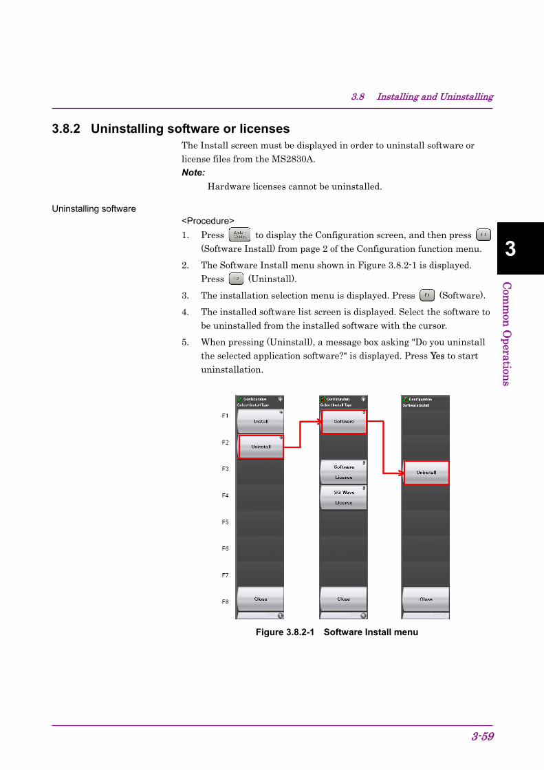
3.8 Installing and Uninstalling
3-59
3
Com
mon
Operation
s
3.8.2 Uninstalling software or licenses The Install screen must be displayed in order to uninstall software or license files from the MS2830A. Note:
Hardware licenses cannot be uninstalled.
Uninstalling software <Procedure> 1. Press to display the Configuration screen, and then press
(Software Install) from page 2 of the Configuration function menu.
2. The Software Install menu shown in Figure 3.8.2-1 is displayed. Press (Uninstall).
3. The installation selection menu is displayed. Press (Software).
4. The installed software list screen is displayed. Select the software to be uninstalled from the installed software with the cursor.
5. When pressing (Uninstall), a message box asking "Do you uninstall the selected application software?" is displayed. Press Yes to start uninstallation.
Figure 3.8.2-1 Software Install menu

Chapter 3 Common Operations
3-60
Uninstalling software licenses <Procedure> 1. Press to display the Configuration screen, and then press
(Software Install) from page 2 of the Configuration function menu.
2. The Software Install menu shown in Figure 3.8.2-2 is displayed. Press (Uninstall).
3. The installation selection menu is displayed. Press (Software License).
4. The installed software license list screen is displayed. Select the software license to be uninstalled from the installed software licenses with the cursor.
5. When pressing (Uninstall), a message box asking "Do you uninstall the selected application software license?" is displayed. Press Yes to start uninstallation.
Figure 3.8.2-2 Software Install menu
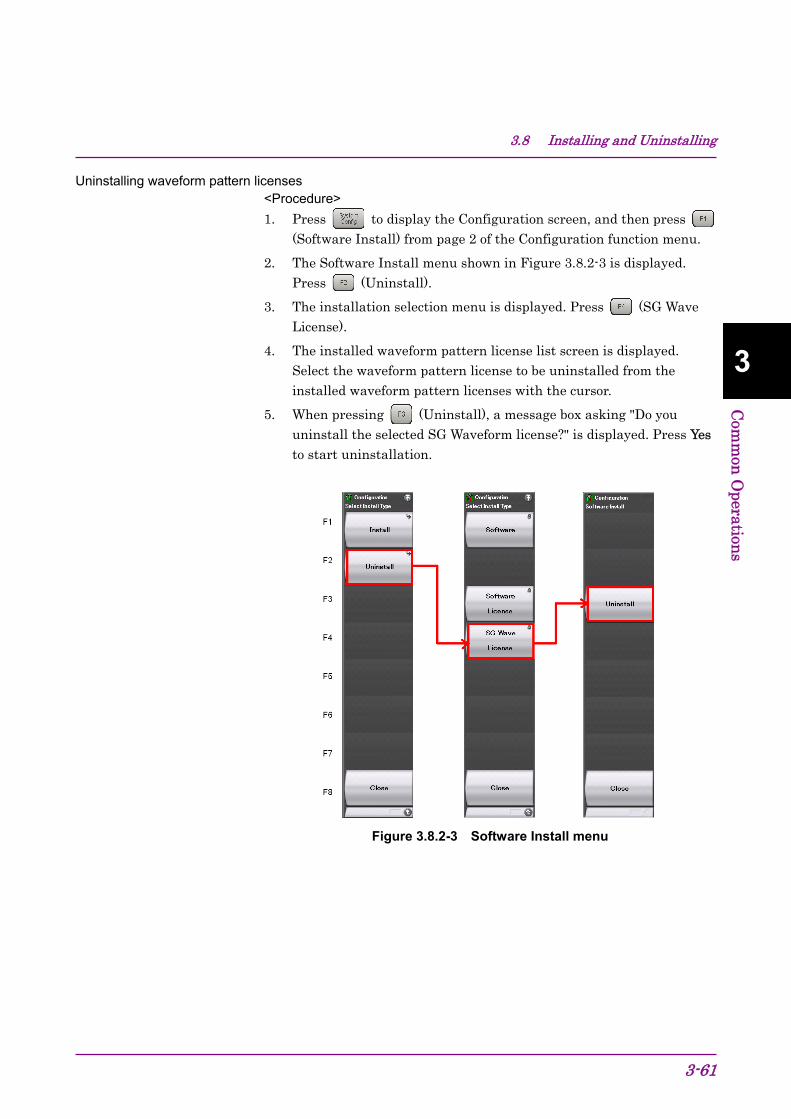
3.8 Installing and Uninstalling
3-61
3
Com
mon
Operation
s
Uninstalling waveform pattern licenses <Procedure> 1. Press to display the Configuration screen, and then press
(Software Install) from page 2 of the Configuration function menu.
2. The Software Install menu shown in Figure 3.8.2-3 is displayed. Press (Uninstall).
3. The installation selection menu is displayed. Press (SG Wave License).
4. The installed waveform pattern license list screen is displayed. Select the waveform pattern license to be uninstalled from the installed waveform pattern licenses with the cursor.
5. When pressing (Uninstall), a message box asking "Do you uninstall the selected SG Waveform license?" is displayed. Press Yes to start uninstallation.
Figure 3.8.2-3 Software Install menu

Chapter 3 Common Operations
3-62.

4-1
4 Tutorial
Chapter 4 Tutorial This chapter describes the waveform display of the signal analyzer and spectrum analyzer.
4.1 Spectrum Analysis Using Signal Analyzer .................... 4-2 4.1.1 Spectrum analysis ............................................ 4-2
4.2 Spectrum Analysis Using Spectrum Analyzer .............. 4-6 4.2.1 Spectrum Analysis ............................................ 4-6

Chapter 4 Tutorial
4-2
4.1 Spectrum Analysis Using Signal Analyzer Option 006/106 is required to use the signal analyzer function.
4.1.1 Spectrum analysis This section describes the operation procedure for displaying input signal waveforms to the application screen of the signal analyzer.
Figure 4.1.1-1 Front panel
Example: Input Signal: Frequency: 1 GHz (CW) Level: 10 dBm
Input signal
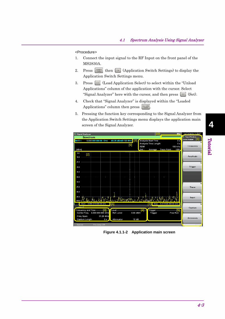
4.1 Spectrum Analysis Using Signal Analyzer
4-3
4 Tutorial
4 Tutorial
<Procedure> 1. Connect the input signal to the RF Input on the front panel of the
MS2830A.
2. Press then (Application Switch Settings) to display the Application Switch Settings menu.
3. Press (Load Application Select) to select within the “Unload Applications” column of the application with the cursor. Select “Signal Analyzer” here with the cursor, and then press (Set).
4. Check that “Signal Analyzer” is displayed within the “Loaded Applications” column then press .
5. Pressing the function key corresponding to the Signal Analyzer from the Application Switch Settings menu displays the application main screen of the Signal Analyzer.
Figure 4.1.1-2 Application main screen
[9] [8]
[10]
[6] [7]
[3] [4] [5]
[2]
[1]

Chapter 4 Tutorial
4-4
Table 4.1.1-1 Display items for Signal Analyzer
Item Description
[1]
This is the main function key of the signal analyzer. Basic parameter settings of the signal analyzer are configured here.
Signal Analyzer Function Operation 2.1 “Display Description”
[2] Displays signal waveforms.
[3]
Displays the center frequency, frequency span and other frequency parameters.
Signal Analyzer Function Operation 2.2 “Setting Frequency”
[4]
Displays the reference level, input attenuator value and other level parameters.
Signal Analyzer Function Operation 2.3 “Setting Level”
[5]
Displays the trigger source, trigger level and other trigger parameters.
Signal Analyzer Function Operation 3.2 “Trigger Function”
[6] Displays the start frequency.
Signal Analyzer Function Operation 2.2.3 “Setting start frequency”
[7] Displays the stop frequency.
Signal Analyzer Function Operation 2.2.4 “Setting stop frequency”
[8]
Displays the analysis start time, analysis time span, resolution bandwidth and other Spectrum trace parameters.
Signal Analyzer Function Operation 4.2.1 “What is Spectrum trace?”
[9] Displays marker values.
Signal Analyzer Function Operation 4.2.9 “Setting marker search”
[10] This is used as an indictor expressing an analysis progression rate.
6. Frequency settings must be changed to display the input signal in
the waveform display screen. Press (Frequency).
7. Press (Center Frequency) and then enter the desired frequency using the numeric keypad. The center frequency setup window is displayed.
Figure 4.1.1-3 Center frequency setup window

4.1 Spectrum Analysis Using Signal Analyzer
4-5
4 Tutorial
4 Tutorial
8. Enter the center frequency then select the unit, from GHz, MHz, kHz, and Hz.
Example: To set 1 GHz for the center frequency, press and then (GHz).
The waveform of the input signal is now displayed on the screen (see Figure 4.1.1-4).
Figure 4.1.1-4 Waveform display using Signal Analyzer
Refer to the MS2830A/MS2840A Signal Analyzer Operation Manual (Signal Analyzer Function Operation) for how to use the Signal Analyzer.

Chapter 4 Tutorial
4-6
4.2 Spectrum Analysis Using Spectrum Analyzer 4.2.1 Spectrum Analysis
This section describes the operation procedure for displaying input signal waveforms to the application screen of the spectrum analyzer.
Figure 4.2.1-1 Front panel
Example: Input Signal: Frequency: 1 GHz (CW) Level: −10 dBm
Input signal
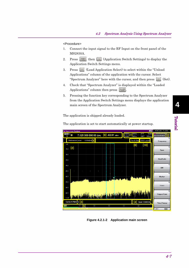
4.2 Spectrum Analysis Using Spectrum Analyzer
4-7
4 Tutorial
4 Tutorial
<Procedure> 1. Connect the input signal to the RF Input on the front panel of the
MS2830A.
2. Press then (Application Switch Settings) to display the Application Switch Settings menu.
3. Press (Load Application Select) to select within the “Unload Applications” column of the application with the cursor. Select “Spectrum Analyzer” here with the cursor, and then press (Set).
4. Check that “Spectrum Analyzer” is displayed within the “Loaded Applications” column then press .
5. Pressing the function key corresponding to the Spectrum Analyzer from the Application Switch Settings menu displays the application main screen of the Spectrum Analyzer.
The application is shipped already loaded.
The application is set to start automatically at power startup.
Figure 4.2.1-2 Application main screen
[1]
[2]
[4] [5]
[6]
[7]
[8]
[9]
[3]
[10]
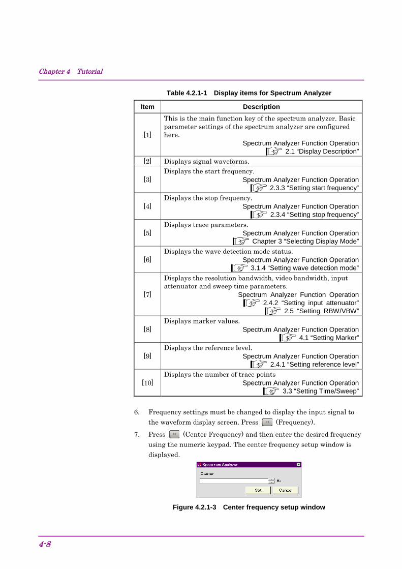
Chapter 4 Tutorial
4-8
Table 4.2.1-1 Display items for Spectrum Analyzer
Item Description
[1]
This is the main function key of the spectrum analyzer. Basic parameter settings of the spectrum analyzer are configured here.
Spectrum Analyzer Function Operation 2.1 “Display Description”
[2] Displays signal waveforms.
[3] Displays the start frequency.
Spectrum Analyzer Function Operation 2.3.3 “Setting start frequency”
[4] Displays the stop frequency.
Spectrum Analyzer Function Operation 2.3.4 “Setting stop frequency”
[5] Displays trace parameters.
Spectrum Analyzer Function Operation Chapter 3 “Selecting Display Mode”
[6] Displays the wave detection mode status.
Spectrum Analyzer Function Operation 3.1.4 “Setting wave detection mode”
[7]
Displays the resolution bandwidth, video bandwidth, input attenuator and sweep time parameters.
Spectrum Analyzer Function Operation 2.4.2 “Setting input attenuator”
2.5 “Setting RBW/VBW”
[8] Displays marker values.
Spectrum Analyzer Function Operation 4.1 “Setting Marker”
[9] Displays the reference level.
Spectrum Analyzer Function Operation 2.4.1 “Setting reference level”
[10] Displays the number of trace points
Spectrum Analyzer Function Operation 3.3 “Setting Time/Sweep”
6. Frequency settings must be changed to display the input signal to
the waveform display screen. Press (Frequency).
7. Press (Center Frequency) and then enter the desired frequency using the numeric keypad. The center frequency setup window is displayed.
Figure 4.2.1-3 Center frequency setup window
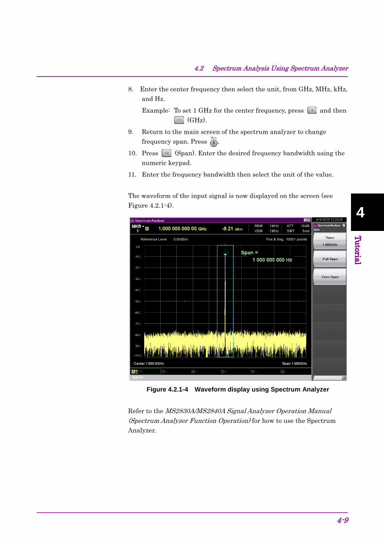
4.2 Spectrum Analysis Using Spectrum Analyzer
4-9
4 Tutorial
4 Tutorial
8. Enter the center frequency then select the unit, from GHz, MHz, kHz, and Hz.
Example: To set 1 GHz for the center frequency, press and then (GHz).
9. Return to the main screen of the spectrum analyzer to change frequency span. Press .
10. Press (Span). Enter the desired frequency bandwidth using the numeric keypad.
11. Enter the frequency bandwidth then select the unit of the value.
The waveform of the input signal is now displayed on the screen (see Figure 4.2.1-4).
Figure 4.2.1-4 Waveform display using Spectrum Analyzer
Refer to the MS2830A/MS2840A Signal Analyzer Operation Manual (Spectrum Analyzer Function Operation) for how to use the Spectrum Analyzer.

Chapter 4 Tutorial
4-10.

5-1
5 System
Chapter 5 System The MS2830A uses one of the following Microsoft Windows (hereinafter, referred to as “Windows”) as the operating system (hereinafter, OS). • Windows Embedded Standard 2009 (hereinafter, WES 2009) • Windows Embedded Standard 7 64 bit ver. (hereinafter, WES 7) • Windows 10 IoT 64 bit ver. (hereinafter, Win 10) Settings for Windows and the system can be operated by connecting a mouse and a keyboard. This section describes how to perform operations on Windows installed to the MS2830A and general notes.
5.1 Setting Windows ......................................................... 5-2 5.1.1 Displaying Windows Desktop .......................... 5-3 5.1.2 Setting Control Panel ...................................... 5-4 5.1.3 Using external display ..................................... 5-6 5.1.4 General notes ............................................... 5-11
5.2 Storage Device Configuration .................................... 5-12 5.3 System Recovery Functions ...................................... 5-13
5.3.1 Phoenix Recover Pro .................................... 5-16 5.3.2 Paragon Drive Backup .................................. 5-17 5.3.3 Windows Backup........................................... 5-18
5.4 Windows Security Measures ..................................... 5-19 5.4.1 Activating Firewall ......................................... 5-21 5.4.2 Installing Important Windows Update Programs
(Windows Update)......................................... 5-34 5.4.3 Using Antivirus Software ............................... 5-38

Chapter 5 System
5-2
5.1 Setting Windows The MS2830A is set to default settings at factory shipment so as to perform optimal measurements. Changing the Windows settings without instructions is outside the scope of operation warranty. In addition, performance may drop or functions may not operate correctly when Windows settings are changed. Carefully read the general notes of this section when changes to Windows settings are required.
When the system fails to operate correctly due to Windows operation, execute system recovery functions to restore the MS2830A to its status at factory shipment. See 5.3 “System Recovery Functions” for details.
WARNING MS2830A operations are not guaranteed when the Windows settings are changed from the default shipment status without instructions.
Installing a program not recommended or admitted by Anritsu Corporation is prohibited by the license with Microsoft. However, it is the customer's responsibility to purchase, install, and operate antivirus software.
WARNING Performing system recovery will cause software installation (including updates) after factory shipment of the MS2830A and application settings to be lost. In addition, data (measurements, parameters, etc.) recorded by the customer may be deleted depending on the method to perform system recovery.

5.1 Setting Windows
5-3
5 System
5.1.1 Displaying Windows Desktop Connect a mouse and a keyboard to operate Windows. Use the USB mouse included as standard equipment and a compatible keyboard (USB).
The following are methods to display the Windows Desktop. To display applications of the MS2830A again, press or select an application in the Windows Taskbar.
Show Windows desktop Mouse Right-click anywhere on the screen, and click the Show the Desktop
on the displayed list to display the Windows desktop. Click the “Minimize” button located in the upper right corner of the
application window of the MS2830A. Minimizing all applications displays the Windows desktop.
Keyboard Pressing the Windows logo key + D minimizes all windows and
displays the Windows Desktop.
Show Start button When the OS is WES 2009 The Start button appears on the left side of the Windows taskbar at
the bottom of the Windows desktop. On the application window, move the mouse pointer to the bottom of
the screen to display the Windows taskbar. The Start button appears on the left side of the Windows taskbar.
When the OS is WES 7 or Win 10 On the Windows desktop, move the mouse pointer to the bottom of the
screen to display the Windows taskbar. The Start button or Start icon appears on the left side of the Windows taskbar.
Show Start menu Mouse Click the Start button or Start icon to display the start menu.
Keyboard Press the Windows logo key to display the start menu.
Show Control Panel When the OS is WES 2009 or WES 7 Click the Control Panel in the start menu.
When the OS is Win 10 Click Windows System > Control Panel in the W column of the app list
displayed.

Chapter 5 System
5-4
5.1.2 Setting Control Panel Various Windows settings can be configured using the Control Panel. The following describes general notes on each setting. Although each setting can be configured without using the Control Panel, use within the scope of the following restrictions.
The MS2830A may not operate normally when any other Windows settings are changed from the factory defaults.
Program and Hardware • Do not delete the installed devices or update/delete the drivers.
• The MS2830A may not operate normally due to conflicts with device drivers when new hardware is added.
• Do not update or remove programs installed at the factory.
• Anritsu does not warrant operations of the MS2830A when programs not guaranteed are installed.
Windows Update • Automatic updating of Windows is turned off at the factory.
Refer to 5.4 “Windows Security Measures” for details.
Network Connection • TCP/IP settings may change when the MS2830A is remote-controlled
through Ethernet. For details, refer to the MS2690A/MS2691A/MS2692A and MS2830A/MS2840A/MS2850A Signal Analyzer Operation Manual (Mainframe Remote Control).
• The IP address is set to use DHCP before shipment from the factory. Ensure that the network administrator settings are appropriate when connecting the MS2830A to a network.
User Account • Automatic login with the following settings is enabled at the factory.
Do not change the User Account settings shown below. Account Name “ANRITSU” Password (None) (WES 2009 or WES 7) “ANRITSU” (Win 10) Account Type Computer Administrator
• New user accounts can be created. Specify “Computer Administrator” for the account type of the user account to be created. Applications will not start up normally with user accounts created using Limited (Power User).
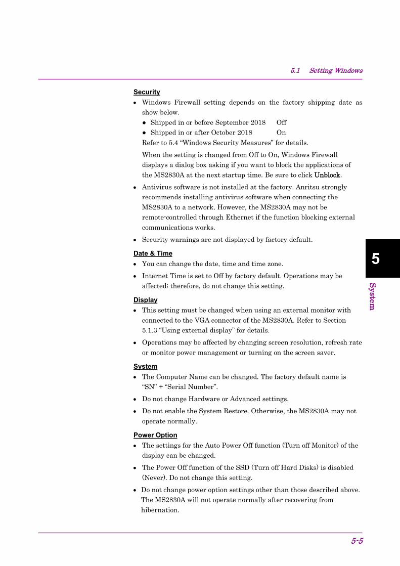
5.1 Setting Windows
5-5
5 System
Security • Windows Firewall setting depends on the factory shipping date as
show below. Shipped in or before September 2018 Off Shipped in or after October 2018 On Refer to 5.4 “Windows Security Measures” for details. When the setting is changed from Off to On, Windows Firewall displays a dialog box asking if you want to block the applications of the MS2830A at the next startup time. Be sure to click Unblock.
• Antivirus software is not installed at the factory. Anritsu strongly recommends installing antivirus software when connecting the MS2830A to a network. However, the MS2830A may not be remote-controlled through Ethernet if the function blocking external communications works.
• Security warnings are not displayed by factory default.
Date & Time • You can change the date, time and time zone.
• Internet Time is set to Off by factory default. Operations may be affected; therefore, do not change this setting.
Display • This setting must be changed when using an external monitor with
connected to the VGA connector of the MS2830A. Refer to Section 5.1.3 “Using external display” for details.
• Operations may be affected by changing screen resolution, refresh rate or monitor power management or turning on the screen saver.
System • The Computer Name can be changed. The factory default name is
“SN” + “Serial Number”.
• Do not change Hardware or Advanced settings.
• Do not enable the System Restore. Otherwise, the MS2830A may not operate normally.
Power Option • The settings for the Auto Power Off function (Turn off Monitor) of the
display can be changed.
• The Power Off function of the SSD (Turn off Hard Disks) is disabled (Never). Do not change this setting.
• Do not change power option settings other than those described above. The MS2830A will not operate normally after recovering from hibernation.
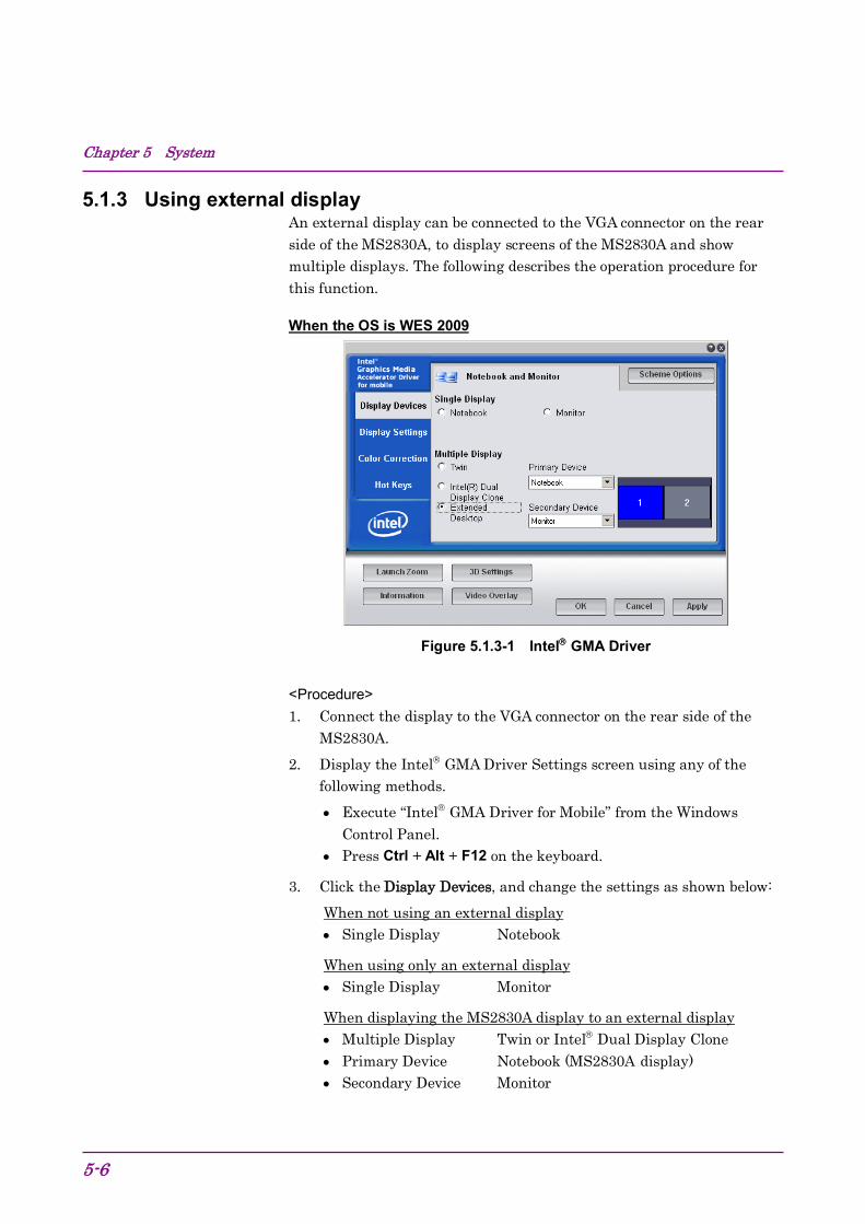
Chapter 5 System
5-6
5.1.3 Using external display An external display can be connected to the VGA connector on the rear side of the MS2830A, to display screens of the MS2830A and show multiple displays. The following describes the operation procedure for this function.
When the OS is WES 2009
Figure 5.1.3-1 Intel GMA Driver
<Procedure> 1. Connect the display to the VGA connector on the rear side of the
MS2830A. 2. Display the Intel GMA Driver Settings screen using any of the
following methods.
• Execute “Intel GMA Driver for Mobile” from the Windows Control Panel.
• Press Ctrl + Alt + F12 on the keyboard.
3. Click the Display Devices, and change the settings as shown below: When not using an external display • Single Display Notebook
When using only an external display • Single Display Monitor
When displaying the MS2830A display to an external display • Multiple Display Twin or Intel Dual Display Clone • Primary Device Notebook (MS2830A display) • Secondary Device Monitor

5.1 Setting Windows
5-7
5 System
When displaying with the MS2830A and external display connected Multiple Display Extended Desktop Primary Device Notebook (MS2830A display) Secondary Device Monitor
When the OS is WES 7 (Intel Graphics and Media)
Figure 5.1.3-2 Intel Graphics and Media Control Panel
<Procedure> 1. Connect the display to the VGA connector on the rear of the
MS2830A. 2. Open the Intel Graphics and Media Control Panel by the following
method:
• In Control Panel of Windows, launch the Intel Graphics and Media.
3. Click Basic Mode > OK > Display > Multiple Displays, and change settings as shown below: When not using an external display • Operating Mode Single Display • Primary Display Built-in Display (MS2830A display) When using only an external display • Operating Mode Single Display • Primary Display (Connected external display)

Chapter 5 System
5-8
When displaying the same content on each of the MS2830A display and external display Operating Mode Clone Display Primary Device Built-in Display (MS2830A display) Secondary Device (Connected external display) When displaying with the MS2830A and external display connected Operating Mode Extended Desktop Primary Device Built-in Display (MS2830A display) Secondary Device (Connected external display)
When the OS is WES 7 (Intel HD Graphics) <Procedure> 1. Connect the display to the VGA connector on the rear of the
MS2830A. 2. Open the Intel HD Graphics Control Panel by the following method:
In Control Panel of Windows, launch the Intel HD Graphics.
Figure 5.1.3-3 Intel HD Graphics Control Panel (WES 7)

5.1 Setting Windows
5-9
5 System
3. Click the Display to expand the Display menu and select Multiple Displays.
Figure 5.1.3-4 Intel HD Graphics Control Panel (WES 7, Display)
4. Click Display > Multiple Displays, and change the settings as shown below: When not using an external display Select Display Mode Single Select Active Displays Built-in Display (MS2830A display) When using only an external display Select Display Mode Single Select Active Displays Monitor (Connected external display) When displaying the same content on each of the MS2830A display and external display Select Display Mode Clone Select Active Displays Built-in Display, Monitor When displaying with the MS2830A and external display connected Select Display Mode Extended Select Active Displays (1) Built-in Display, (2) Monitor
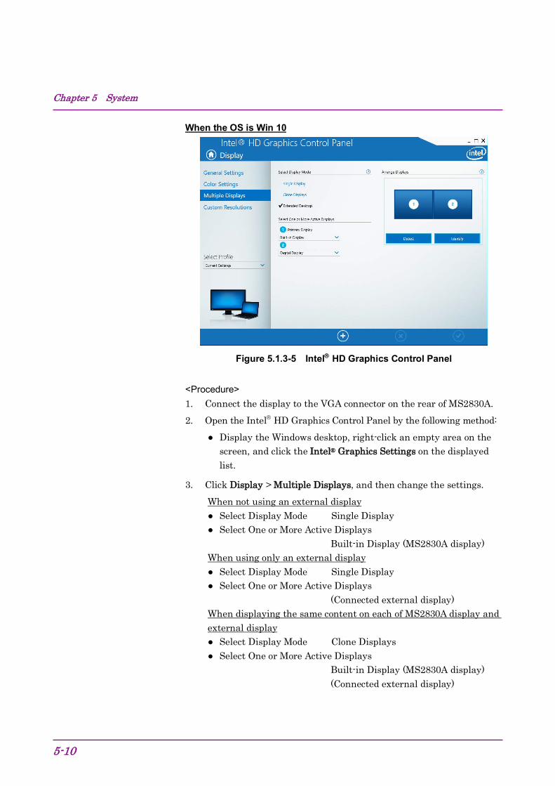
Chapter 5 System
5-10
When the OS is Win 10
Figure 5.1.3-5 Intel HD Graphics Control Panel
<Procedure> 1. Connect the display to the VGA connector on the rear of MS2830A. 2. Open the Intel HD Graphics Control Panel by the following method:
Display the Windows desktop, right-click an empty area on the screen, and click the Intel® Graphics Settings on the displayed list.
3. Click Display > Multiple Displays, and then change the settings. When not using an external display Select Display Mode Single Display Select One or More Active Displays
Built-in Display (MS2830A display) When using only an external display Select Display Mode Single Display Select One or More Active Displays
(Connected external display) When displaying the same content on each of MS2830A display and external display Select Display Mode Clone Displays Select One or More Active Displays
Built-in Display (MS2830A display) (Connected external display)

5.1 Setting Windows
5-11
5 System
When displaying with MS2830A and external display connected Select Display Mode Extended Desktop Select One or More Active Displays
1. Primary Display Built-in Display (MS2830A display) 2. (Connected external display)
CAUTION Turning the MS2830A power On when an external display is not connected to the VGA connector initializes to mainframe display only. When continuously using an external display, it is recommended to keep the external monitor connected for use.
CAUTION Do not change the resolution, refresh rate or power management settings of the mainframe monitor.
5.1.4 General notes
The MS2830A operations are guaranteed provided it is in factory default settings. The following situations may affect the MS2830A operations.
Install software that is not factory-installed and operate it on the MS2830A. e.g.) Install antivirus software and execute virus scan.
Enable or operate a Windows program service that is disabled or stopped at factory. e.g.) Transfer files by FTP while the MS2830A is running.
In addition to the above, note the below. The MS2830A may not work properly when the registries are changed.
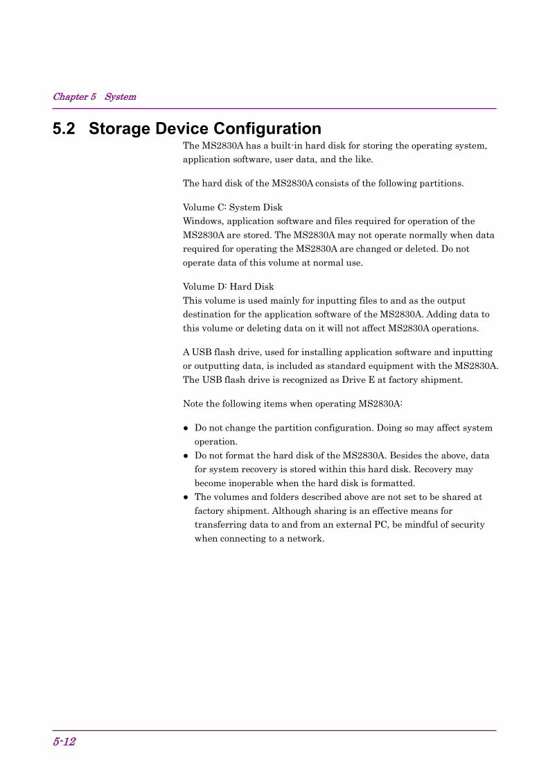
Chapter 5 System
5-12
5.2 Storage Device Configuration The MS2830A has a built-in hard disk for storing the operating system, application software, user data, and the like.
The hard disk of the MS2830A consists of the following partitions.
Volume C: System Disk Windows, application software and files required for operation of the MS2830A are stored. The MS2830A may not operate normally when data required for operating the MS2830A are changed or deleted. Do not operate data of this volume at normal use.
Volume D: Hard Disk This volume is used mainly for inputting files to and as the output destination for the application software of the MS2830A. Adding data to this volume or deleting data on it will not affect MS2830A operations.
A USB flash drive, used for installing application software and inputting or outputting data, is included as standard equipment with the MS2830A. The USB flash drive is recognized as Drive E at factory shipment.
Note the following items when operating MS2830A:
Do not change the partition configuration. Doing so may affect system operation.
Do not format the hard disk of the MS2830A. Besides the above, data for system recovery is stored within this hard disk. Recovery may become inoperable when the hard disk is formatted.
The volumes and folders described above are not set to be shared at factory shipment. Although sharing is an effective means for transferring data to and from an external PC, be mindful of security when connecting to a network.

5.3 System Recovery Functions
5-13
5 System
5.3 System Recovery Functions The MS2830A has system recovery functions to restore data on the hard disk to the factory default. These functions can be used in the event of system instability.
When the OS is WES 2009 or WES 7 The MS2830A comes with factory-installed recovery software, Phoenix Recover Pro or Paragon Drive Backup. To confirm the installed recovery software, start the MS2830A, and press the F4 on the BIOS screen to start the recovery software.
<Procedure> 1. Disconnect the MS2830A from the network if connected. 2. Connect the keyboard and mouse to the mainframe, and then turn
the MS2830A power On. The BIOS screen will appear in a few seconds after (The message “Press F2 for System Utilities” appears at the bottom part of the screen).
3. Press the F4 (not on the front panel of the mainframe) while the screen in Step 2 is displayed.
4. Only when the screen displays the message “Press F4 to start recovery from Backup Capsule”, press the F4 again.
5. According to the software instructions on the screen, perform a system recovery. Phoenix Always Refer to Section 5.3.1 “Phoenix Recover Pro”. Paragon Drive Backup Refer to Section 5.3.2 “Paragon Drive Backup”.
Chapter 5 System
5-14
CAUTION To execute these functions, understand the following items for their use.
All applications and updates added after factory shipment will be lost. Additionally, all data recorded to Volume C will be restored to the factory default. Backup important data before executing these functions.
The user data area of Volume D can be restored to the factory default depending on the function to be selected. So as not to lose important user data due to incorrect operations, it is recommended to backup data in Volume D before executing these functions.
Data deleted by these functions cannot be restored.
When the Paragon Drive Backup software is installed, the backup data is saved to an unknown partition on the Disk 0. If the unknown partition is accidentally deleted, the backup data required for system recovery is deleted as well.
5.3 System Recovery Functions
5-15
5 System
When the OS is Win 10 The MS2830A has the standard Windows system recovery functions. See 5.3.3 “Windows Backup” for the system recovery procedure.
CAUTION To execute these functions, understand the following items for their use.
All applications and updates added after factory shipment will be lost. Additionally, all data recorded to Volume C and D will be restored to the factory default. Backup important data before executing these functions.
Unlike WES 2009 and WES 7, the Win 10 system recovery functions cannot restore only Volume C to the factory default. Data stored on both Volume C and D will be restored to the factory default.
Data deleted by these functions cannot be restored.

Chapter 5 System
5-16
5.3.1 Phoenix Recover Pro This subsection describes how to perform a system recovery with factory-installed recovery software “Phoenix Recover Pro”.
Restore System drive (partition) only This function restores only Volume C, in which Windows, application software, and files required for operations of the MS2830A are stored, to the factory default.
Restore entire hard disk This function restores Volume C and Volume D to the factory default. Although Volume D is mainly used as a storage area for user data, all data on Volume D will be erased.
<Procedure> 1. After the screen displaying “Phoenix Always” appears, the following
alternatives are displayed on the screen: Restore System drive (partition) only
Recovers only Volume C. Restore entire hard disk
Recovers Volumes C and D.
Select one of the two alternatives, and then click NEXT. To cancel, press and hold the Power Switch of the mainframe to power off.
2. After clicking NEXT, the confirmation screen appears. Click OK to start a system recovery. Although the required time for recovery varies depending on the conditions, it normally takes between 10 and 30 minutes. The progress of recovery is shown during recovery. Although the progress indicator may close during recovery, this is a normal operation.
The MS2830A will restart automatically then normal startup will be executed.
5.3 System Recovery Functions
5-17
5 System
5.3.2 Paragon Drive Backup This subsection describes how to perform a system recovery with factory-installed recovery software “Paragon Drive Backup”.
Type: Partition This function restores only Volume C, in which Windows, application software, and files required for operations of the MS2830A are stored, to the factory default.
Type: Disk This function restores Volume C and Volume D to the factory default. Although Volume D is mainly used as a storage area for user data, all data on Volume D will be erased.
<Procedure> 1. After the screen displaying “Drive Backup” appears, the following
alternatives are displayed on the screen: Normal Mode
Safe Mode
Select Normal Mode with the arrow keys, and then press the Enter. 2. When the menu screen appears in about a minute, double-click
Simple Restore Wizard. 3. The Paragon Simple Restore Wizard appears, so click Next. 4. The following alternatives are displayed on the screen: Type: Partition
Recovers only Volume C. Type: Disk
Recovers Volumes C and D. Double-click either of them, and then click Next. 5. When the confirmation screen appears, click Yes to start a system
recovery. Then, the Progress information screen appears, and the recovery process starts. Do not click Cancel when a system recovery is in progress. Although the required time for recovery varies depending on the conditions, it normally takes between 10 and 30 minutes. The progress of recovery is shown during recovery. Although the progress indicator may close during recovery, this is a normal operation.
6. Upon completion of the recovery process, click Close. (Close appears after the recovery process is completed.)
7. When the completion screen appears, click Finish to return to the menu screen described in Step 5. Click Reboot the computer to reboot the MS2830A, or click Power off to turn the power Off.

Chapter 5 System
5-18
5.3.3 Windows Backup This subsection describes how to perform a system recovery when the installed OS is Win 10.
<Procedure> 1. Disconnect the MS2830A from the network if connected. 2. Connect the keyboard and mouse to the mainframe, and then turn
the MS2830A power On. 3. While the Anritsu logo is displayed, press F8 on the keyboard. 4. The boot options menu is launched. Select Repair Your computer,
and then press the Enter. 5. The Choose an option appears, select Troubleshoot, and press Enter. 6. The Troubleshoot appears, select Advanced options, and press Enter. 7. The Advanced options appears, select System Image Recovery, and
press Enter. 8. The System Image Recover appears, select ANRITSU, and press Enter. 9. When you are prompted to enter a password, enter “ANRITSU”, and
then click Continue.
10. The Select a system image backup appears, select Use the latest available system image (recommended), and click Next.
11. The Choose additional restore options appears, and click Next without any changes.
12. When “Your computer will be restored from the following system image:” appears, click Finish.
13. When the confirmation screen appears, click Yes to start a system recovery. The Progress bar appears, and the recovery process starts. Do not click Stop restore when a system recovery is in progress. Although the required time for recovery varies depending on the conditions, it normally takes between 20 and 30 minutes.
14. After the system recovery is completed, the MS2830A restarts automatically, and Windows starts.
5.4 Windows Security Measures
5-19
5 System
5.4 Windows Security Measures To apply security measures described in this section, the MS2830A must run WES 7 or Win 10. The following options upgrade the CPU and operating system.
MS2830A-182: Upgrades to Win 10. In terms of security measures and antivirus, we do not recommend connecting the MS2830A running WES 2009 to a network.
“C1” label is affixed on the rear panel of the MS2830A that runs on WES 7. “C2” label is affixed on the rear panel of the MS2830A that runs on Win 10.
When connecting the MS2830A with WES 7 or Win 10 to a network, make sure the network is secure and protected from viruses. Additionally, it is recommended to take the following security measures to add protection against malware (malicious software such as viruses). Activating firewall Installing important Windows update programs Using antivirus software
The security measure settings condition of the MS2830A can be confirmed from the Control Panel of Windows.
When the OS is WES 7 1. Use the mouse to right-click anywhere on the screen, and click Show
the desktop to reveal the Windows desktop. 2. Move the mouse pointer to the bottom of the screen to display the
Windows taskbar. Click Start > Control Panel. 3. Set “View by: Category” at the upper right of the Control Panel, click
System and Security > Action Center. 4. Click Security, and confirm security measures settings condition.
When the OS is Win 10 1. Use the mouse to right-click anywhere on the screen, and click Show
the desktop to reveal the Windows desktop. 2. Move the mouse pointer to the bottom of the screen to display the
Windows task bar. Click the Start icon to open the Start menu, and then click Windows System > Control Panel in the W column of the app list displayed.
3. Set “View by: Category” at the upper right of the Control Panel, click System and Security > Security and Maintenance.
4. Click Security, and confirm security measures settings condition.
Note: Security warnings are not displayed by factory default.
Chapter 5 System
5-20
CAUTION If the MS2830A is connected to an external network like the Internet, there may be a risk of causing unexpected problems or suffering unexpected losses. Anritsu Corporation is not responsible for any losses caused by connecting it to a network.
CAUTION Adding any options or repair may restore the Windows settings to factory default settings. In this case, reinstall Windows updates, turn the firewall on again, and reinstall antivirus software.
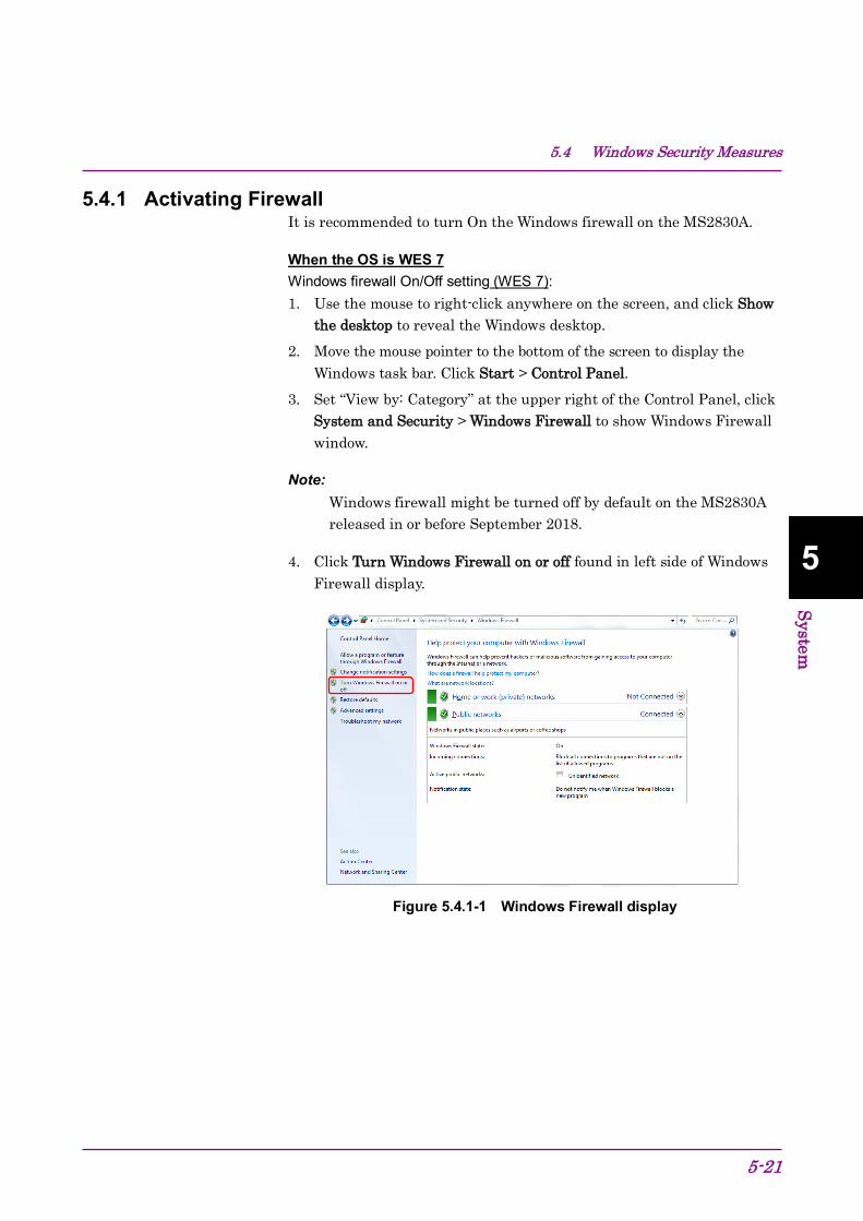
5.4 Windows Security Measures
5-21
5 System
5.4.1 Activating Firewall It is recommended to turn On the Windows firewall on the MS2830A.
When the OS is WES 7 Windows firewall On/Off setting (WES 7): 1. Use the mouse to right-click anywhere on the screen, and click Show
the desktop to reveal the Windows desktop. 2. Move the mouse pointer to the bottom of the screen to display the
Windows task bar. Click Start > Control Panel. 3. Set “View by: Category” at the upper right of the Control Panel, click
System and Security > Windows Firewall to show Windows Firewall window.
Note: Windows firewall might be turned off by default on the MS2830A released in or before September 2018.
4. Click Turn Windows Firewall on or off found in left side of Windows Firewall display.
Figure 5.4.1-1 Windows Firewall display

Chapter 5 System
5-22
5. Customize Settings display will be shown where Windows firewall On/Off settings can be changed.
Use the MS2830A with the following checkboxes Off (unchecked). Block all incoming connections, including those in the list of
allowed programs Notify me when Windows Firewall blocks a new program
Figure 5.4.1-2 Customize Settings display
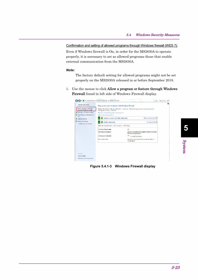
5.4 Windows Security Measures
5-23
5 System
Confirmation and setting of allowed programs through Windows firewall (WES 7):
Even if Windows firewall is On, in order for the MS2830A to operate properly, it is necessary to set as allowed programs those that enable external communication from the MS2830A.
Note: The factory default setting for allowed programs might not be set properly on the MS2830A released in or before September 2018.
1. Use the mouse to click Allow a program or feature through Windows Firewall found in left side of Windows Firewall display.
Figure 5.4.1-3 Windows Firewall display

Chapter 5 System
5-24
2. Allowed Programs display will be shown where programs allowed through Windows firewall can be confirmed. Confirm if MS269xA AppMgr is found and set to On (checked) under Allowed programs and features. When no such information is displayed, it is necessary to add MS269xA AppMgr.
Figure 5.4.1-4 Allowed Programs display
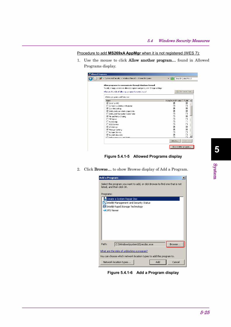
5.4 Windows Security Measures
5-25
5 System
Procedure to add MS269xA AppMgr when it is not registered (WES 7):
1. Use the mouse to click Allow another program… found in Allowed Programs display.
Figure 5.4.1-5 Allowed Programs display
2. Click Browse… to show Browse display of Add a Program.
Figure 5.4.1-6 Add a Program display
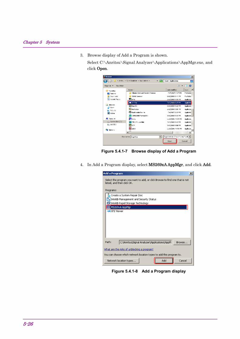
Chapter 5 System
5-26
3. Browse display of Add a Program is shown. Select C:\Anritsu\Signal Analyzer\Applications\AppMgr.exe, and click Open.
Figure 5.4.1-7 Browse display of Add a Program
4. In Add a Program display, select MS269xA AppMgr, and click Add.
Figure 5.4.1-8 Add a Program display
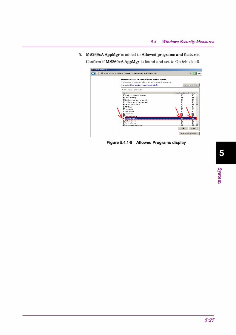
5.4 Windows Security Measures
5-27
5 System
5. MS269xA AppMgr is added to Allowed programs and features. Confirm if MS269xA AppMgr is found and set to On (checked).
Figure 5.4.1-9 Allowed Programs display
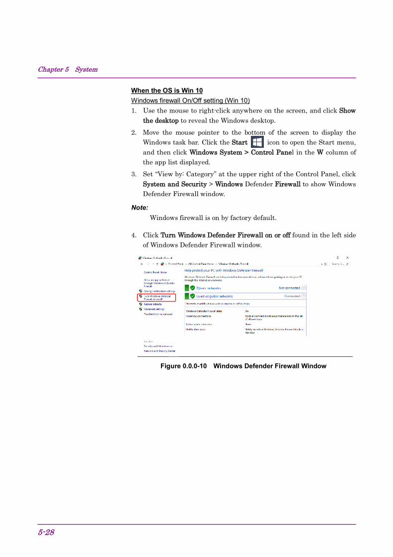
Chapter 5 System
5-28
When the OS is Win 10 Windows firewall On/Off setting (Win 10) 1. Use the mouse to right-click anywhere on the screen, and click Show
the desktop to reveal the Windows desktop. 2. Move the mouse pointer to the bottom of the screen to display the
Windows task bar. Click the Start icon to open the Start menu, and then click Windows System > Control Panel in the W column of the app list displayed.
3. Set “View by: Category” at the upper right of the Control Panel, click System and Security > Windows Defender Firewall to show Windows Defender Firewall window.
Note: Windows firewall is on by factory default.
4. Click Turn Windows Defender Firewall on or off found in the left side of Windows Defender Firewall window.
Figure 0.0.0-10 Windows Defender Firewall Window

5.4 Windows Security Measures
5-29
5 System
5. Customize Settings window will be shown where Windows firewall On/Off settings can be changed.
Use the MS2830A with the following checkboxes Off (unchecked). Block all incoming connections, including those in the list of
allowed apps Notify me when Windows Firewall blocks a new app
Figure 0.0.0-11 Customize Settings Window

Chapter 5 System
5-30
Confirmation and setting of allowed programs through Windows firewall (Win 10) Even if Windows firewall is On, in order for the MS2830A to operate properly, it is necessary to set as allowed programs those that enable external communication from the MS2830A. 1. Use the mouse to click Allow an app or feature through Windows
Defender Firewall found in left side of Windows Defender Firewall window.
Figure 0.0.0-12 Windows Defender Firewall Window
2. Allowed apps window will be shown where programs allowed through Windows firewall can be confirmed. Confirm if MS269xA AppMgr is found and set to On (checked) under Allowed apps and features.
When no such information is displayed, it is necessary to add MS269xA AppMgr.
Figure 0.0.0-13 Allowed apps Window

5.4 Windows Security Measures
5-31
5 System
Procedure to add MS269xA AppMgr when it is not registered (Win 10) 1. Use the mouse to click Allow another app… found in Allowed apps
window.
Figure 0.0.0-14 Allowed apps Window
2. Add an app window is shown. Click Browse….
Figure 0.0.0-15 Add an app Window

Chapter 5 System
5-32
3. Browse window of Add an app is shown. Select C:\Anritsu\Signal Analyzer\Applications\AppMgr.exe, and click Open.
Figure 0.0.0-16 Browse Window of Add an app
4. In Add an app window select MS269xA AppMgr, and click Add.
Figure 0.0.0-17 Add an app Window
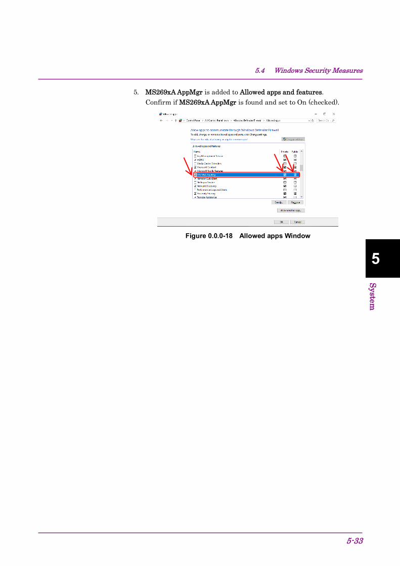
5.4 Windows Security Measures
5-33
5 System
5. MS269xA AppMgr is added to Allowed apps and features. Confirm if MS269xA AppMgr is found and set to On (checked).
Figure 0.0.0-18 Allowed apps Window
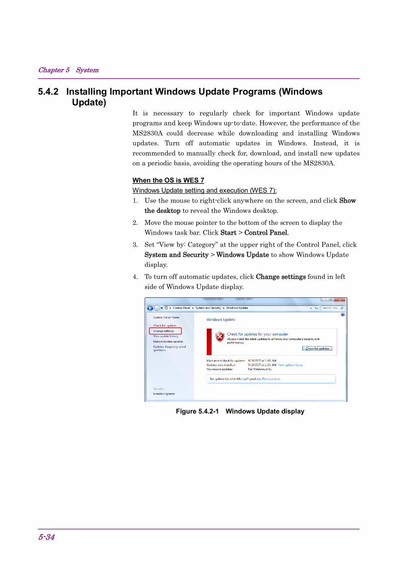
Chapter 5 System
5-34
5.4.2 Installing Important Windows Update Programs (Windows Update)
It is necessary to regularly check for important Windows update programs and keep Windows up-to-date. However, the performance of the MS2830A could decrease while downloading and installing Windows updates. Turn off automatic updates in Windows. Instead, it is recommended to manually check for, download, and install new updates on a periodic basis, avoiding the operating hours of the MS2830A.
When the OS is WES 7 Windows Update setting and execution (WES 7): 1. Use the mouse to right-click anywhere on the screen, and click Show
the desktop to reveal the Windows desktop. 2. Move the mouse pointer to the bottom of the screen to display the
Windows task bar. Click Start > Control Panel. 3. Set “View by: Category” at the upper right of the Control Panel, click
System and Security > Windows Update to show Windows Update display.
4. To turn off automatic updates, click Change settings found in left side of Windows Update display.
Figure 5.4.2-1 Windows Update display

5.4 Windows Security Measures
5-35
5 System
5. Select Never check for updates (not recommended) in Important updates, then click OK.
Figure 5.4.2-2 Change settings display
6. To check for newly available update programs (manual update), click Check for updates in Windows Update display.
Figure 5.4.2-3 Windows Update display (manual update)
7. When a new update program is found, download and install following the displayed instructions.

Chapter 5 System
5-36
When the OS is Win 10 Windows Update setting and execution (Win 10) 1. Use the mouse to right-click anywhere on the screen, and click Show
the desktop to reveal the Windows desktop. 2. Move the mouse pointer to the bottom of the screen to display the
Windows task bar. Click the Start icon to open the Start menu, and then click Settings icon.
3. Click Update and Security to show Windows Update window. 4. To turn off automatic updates, select Windows Update found in left
side of Windows Update window, and then click Advanced options.
Figure 0.0.0-4 Windows Update Window

5.4 Windows Security Measures
5-37
5 System
5. Advanced options window will be shown. Confirm if Automatically download updates. even over metered data connections (charges may apply) is set to Off.
Figure 0.0.0-5 Advanced options Window
6. To check for newly available update programs (manual update), click Check for updates in Windows Update window.
Figure 0.0.0-6 Windows Update Window (manual update)
7. When a new update program is found, download and install following the displayed instructions.
Chapter 5 System
5-38.
5.4.3 Using Antivirus Software It is recommended to install antivirus software on the MS2830A. However, if the antivirus software updates virus definition data automatically or runs full scan in the background, the performance of the MS2830A could decrease. Do not allow the software to execute them. Instead, it is recommended to manually run them on a periodic basis, avoiding the operating hours of the MS2830A.
The antivirus software that checked operation in the MS2830A is shown below.
Trend Micro OfficeScan XG
Note: Refer to the antivirus software operation manual for its installation and operation procedures. It is confirmed that no negative effects in the general usage of the MS2830A are caused by using the software mentioned above, however, we do not guarantee the behavior of all functions of this antivirus software and other software containing similar functions.
6-1
6
Perform
ance Test
Performance Test Chapter 6
This chapter describes measurement devices, setup methods, and performance test procedures required for performing performance tests as preventive maintenance of the MS2830A.
6.1 Overview of Performance Test ..................................... 6-2 6.1.1 Performance test .............................................. 6-2 6.1.2 Performance test items and instruments used . 6-3
6.2 Performance Test Items ............................................... 6-5 6.2.1 Display frequency accuracy ............................. 6-6 6.2.2 Frequency span display accuracy .................... 6-8 6.2.3 Single sideband noise level ............................ 6-10 6.2.4 RF frequency characteristics .......................... 6-13 6.2.5 Display average noise level ............................ 6-18 6.2.6 Second harmonic wave distortion .................. 6-24

Chapter 6 Performance Test
6-2
6.1 Overview of Performance Test 6.1.1 Performance test
Performance tests are performed as part of preventive maintenance in order to prevent the performance of the MS2830A from being degraded before it occurs.
Use performance tests when required for acceptance inspection, routine inspection and performance verification after repairs. Perform items deemed critical at regular intervals as preventive maintenance. Perform the following performance tests for acceptance inspection, routine inspection and performance verification after repairs of the MS2830A.
Display frequency accuracy
Frequency span display accuracy
Single sideband noise level
RF frequency characteristics
Display average noise level
Second harmonic wave distortion
Perform items deemed critical at regular intervals as preventive maintenance. A recommended cycle for routine tests of once or twice a year is desirable.
If items that do not meet the required level are detected during performance testing, contact an Anritsu Service and Sales office. Contact information is available in a separate file (for the PDF version), and on the last page of this manual (for the printed version).

6.1 Overview of Performance Test
6-3
6
Perform
ance Test
6.1.2 Performance test items and instruments used Table 6.1.2-1 lists measuring instruments used or performance tests.
Table 6.1.2-1 List of measuring instruments for performance test
Test Items Required Performance Name of Recommended
Device (Model Name)
Display frequency accuracy Frequency range: 500 MHz to 31 GHz 1 Hz resolution available
Output level range: 20 to 0 dBm 0.1 dB resolution available
Signal generator (MG3691C/92C/94C) With Option 004 or 005
Frequency span display accuracy
Frequency range: 300 MHz to 40 GHz 1 Hz resolution available
Output level range: 20 to 0 dBm 0.1 dB resolution available
Signal generator (MG3691C/92C/94C) With Option 004 or 005
Single sideband noise level Frequency range: 1 GHz, 1 MHz offset1 Hz resolution available
Output level range: 10 to 10 dBm 0.1 dB resolution available
SSB phase noise: 130 dBc/Hz or less (at 100 kHz offset)
SSB phase noise: 150 dBc/Hz or less (at 1 MHz offset)
External reference input: (10 MHz) available
Signal generator (HP8665B Equivalent)

Chapter 6 Performance Test
6-4
Table 6.1.2-1 List of measuring instruments for performance test (Cont’d)
Test Items Required Performance Name of Recommended
Device (Model Name)
RF frequency characteristics
Frequency range: 10 MHz to 40 GHz 1 Hz resolution available
Output level range: 20 to 0 dBm 0.1 dB resolution available
Signal generator (MG3710A) 6 GHz or less Signal generator (MG3691C/92C/94C) 6 GHz or more
Frequency range: 10 MHz to 40 GHz Measurement power range –67 to +20
dBm Mainframe accuracy ±0.02 dB
Power meter (ML2488B)
Power sensor (MA2444D)
Display average noise level Frequency range: DC to 43 GHz VSWR: 1.2 or less 50 Ω
MS2830A-040/041/043/044 Standard terminator (28N50-2) MS2830A-045 Standard terminator (28K50)
Second harmonic wave distortion
Frequency range: 50 MHz to 6.75 GHz External reference input: (10 MHz)
available Second harmonic wave: 30 dBc or less At 2 frequency of SG output:
Loss < 40 dB (LPF)
Signal generator (MG3710A) 6 GHz or less Signal generator (MG3692C) 6 GHz or more Low pass filter SLP-50+ VLF-400 (+) VLF-2250 (+) VLF-3000+ VLF-6000(+) VLF-6700+
: fc=55 MHz : fc=560 MHz : fc=2575 MHz: fc=3600 MHz: fc=6800 MHz: fc=7600 MHz

6.2 Performance Test Items
6-5
6
Perform
ance Test
6.2 Performance Test Items Warm up the subject testing device and measuring instruments for at least 30 minutes except where directed, in order to stabilize them sufficiently before running performance tests. Demonstrating maximum measurement accuracy requires, in addition to the above, conducting performance tests under ambient temperatures, little AC power supply voltage fluctuations, as well as the absence of noise, vibrations, dust, humidity or other problems.
Figure 6.2-1 Performance test
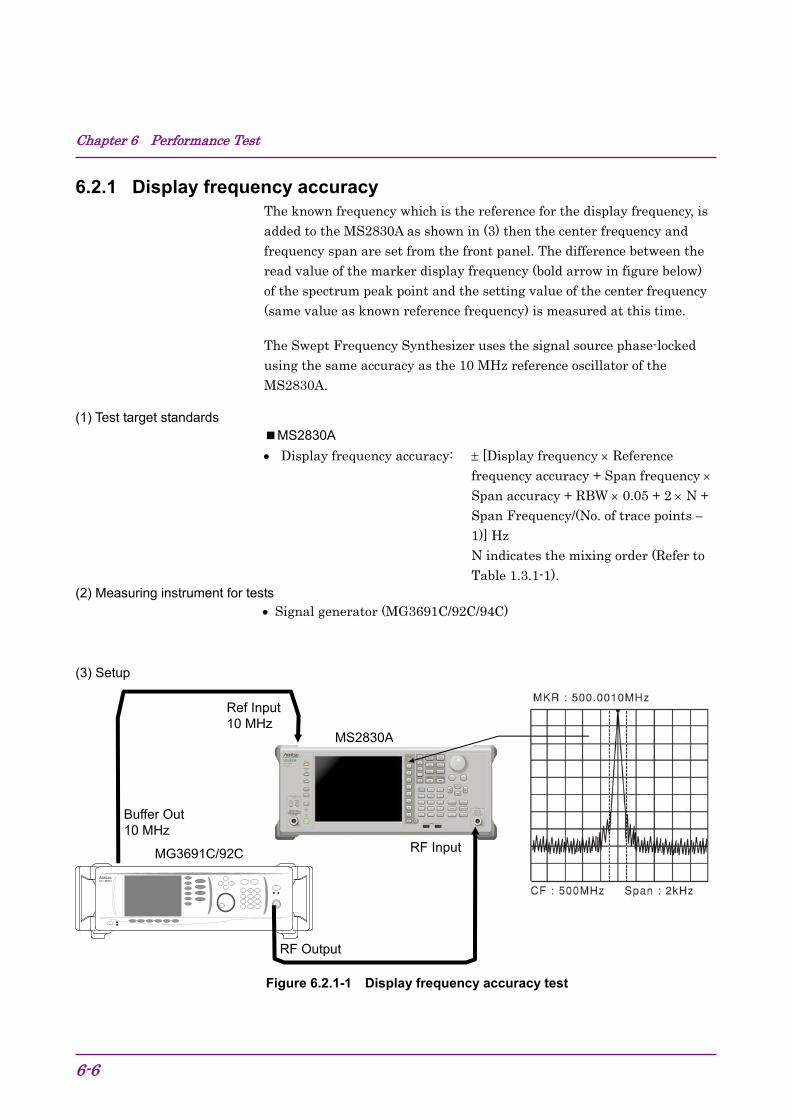
Chapter 6 Performance Test
6-6
6.2.1 Display frequency accuracy The known frequency which is the reference for the display frequency, is added to the MS2830A as shown in (3) then the center frequency and frequency span are set from the front panel. The difference between the read value of the marker display frequency (bold arrow in figure below) of the spectrum peak point and the setting value of the center frequency (same value as known reference frequency) is measured at this time.
The Swept Frequency Synthesizer uses the signal source phase-locked using the same accuracy as the 10 MHz reference oscillator of the MS2830A.
(1) Test target standards MS2830A Display frequency accuracy: [Display frequency Reference
frequency accuracy + Span frequency Span accuracy + RBW 0.05 + 2 N + Span Frequency/(No. of trace points 1)] Hz N indicates the mixing order (Refer to Table 1.3.1-1).
(2) Measuring instrument for tests Signal generator (MG3691C/92C/94C)
(3) Setup
Figure 6.2.1-1 Display frequency accuracy test
Anritsu M キ 3692A
MS2830A
Buffer Out 10 MHz
RF Output
Ref Input 10 MHz
MG3691C/92C RF Input

6.2 Performance Test Items
6-7
6
Perform
ance Test
(4) Notes on test Set the output level of the MG3691C/92C/94C to 20 to 10 dBm
(5) Test procedure 1. Press of the MS2830A, and then select the Spectrum
Analyzer.
2. Press of the MS2830A.
3. Press (Preset) to perform Preset.
4. Press of the MS2830A to display the Frequency function menu.
5. Set the output frequency of the MG3691C/92C/94C to the center frequency (500 MHz) shown in the Display Frequency Accuracy table of Appendix A.
6. Set the center frequency shown in the Display Frequency Accuracy table of Appendix A to the MS2830A.
7. Set the frequency span (10 kHz) and the resolution bandwidth (300 Hz) corresponding to the center frequency (500 MHz) shown in the Display Frequency Accuracy table of Appendix A to the MS2830A.
8. Read the marker frequency value (MKR value) shown on the screen, then check whether this value is within the range of the maximum value and minimum value in the specified range shown in the Display Frequency Accuracy table of Appendix A.
9. Repeat Steps 5 to 8 for the center frequency and frequency span according to the center frequency and frequency span combination shown in the Display Frequency Accuracy table of Appendix A.

Chapter 6 Performance Test
6-8
6.2.2 Frequency span display accuracy Set to the signal generator the frequencies of the first div and ninth div from the left edge of the screen as shown in (3), and read their frequency difference to obtain the span accuracy.
(1) Test target standards MS2830A Frequency span accuracy: 0.2%
(2) Measuring instrument for tests Signal generator (MG3691C/92C/94C)
(3) Setup
Figure 6.2.2-1 Frequency span display accuracy test
MS2830A
RF Input
Buffer Out 10MHz
Ref Input 10 MHz
RF Output
Anritsu M キ 36 92A
MG3691C/92C
Frequencymeasured with
SG
6.2 Performance Test Items
6-9
6
Perform
ance Test
(4) Notes on test Although the output level of the MG3691C/92C/94C is not specified, set normally to 10 to 0 dBm.
(5) Test procedure 1. Press of the MS2830A, and then select the Spectrum
Analyzer.
2. Press of the MS2830A.
3. Press (Preset) to perform Preset.
4. Connect the output of the MG3691C/92C/94C to the RF input of the MS2830A.
5. Set the frequency span (10 kHz) and center frequency (1.8 GHz) of the MS2830A from the Frequency Span Display Accuracy table of Appendix A.
6. Set the output frequency of the MG3691C/92C/94C to the frequency (1799.996 MHz) for f1 shown in the Frequency Span Display Accuracy table of Appendix A.
7. Measure the spectrum waveform peak frequency by using the marker function of the MS2830A. This frequency is set to f1’.
8. Set to the frequency of output frequency f2 of the MG3691C/92C/94C (1800.004 MHz), and then measure the spectrum waveform peak frequency by using the marker function. This frequency is set to f2’.
9. Calculate (f2’ f1’)/0.8/SPAN 100 100 [%] then check whether it satisfies the specified range (minimum value to maximum value) shown in the Frequency Span Display Accuracy table of Appendix A.
10. Repeat Steps 5 to 9 for each frequency span of the center frequency shown in the Frequency Span Display Accuracy table of Appendix A.

Chapter 6 Performance Test
6-10
6.2.3 Single sideband noise level Set the resolution bandwidth to a specific value then input a signal with a single sideband noise level far smaller than the subject test device. Test how far the dB drops from the peak point for a noise level which is distanced by a specific frequency from the spectrum waveform peak point at this time.
Figure 6.2.3-1 Single sideband noise level
(1) Test target standards Single sideband noise: At 18 to 28C, 500 MHz
115 dBc/Hz (Frequency 500 MHz, 100 kHz Offset)
133 dBc/Hz (Frequency 500 MHz, 1 MHz Offset)
(2) Measuring instrument for tests Signal generator (HP8665B)
Sideband Noise
Actual Filter Envelope

6.2 Performance Test Items
6-11
6
Perform
ance Test
(3) Setup
Figure 6.2.3-2 Signal sideband noise level
(4) Notes on test Perform the test at an ambient temperature of 18 to 28C and after warming up for at least 30 minutes.
(5) Test procedure 1. Start the application Spectrum Analyzer of the MS2830A.
2. Press .
3. Press (Preset).
4. Press and then (SIGANA All).
5. Set 500 MHz, 0 dBm for the HP8665B.
6. Set as follows for the MS2830A: Reference level 0 dBm Attenuator 0 dB Center Frequency 500 MHz VBW mode Power Det mode Sample Auto Sweep Time Select Normal Auto Swp Type Rules Swept Only Trace points 1001 Marker Zone Width 100 Hz
7. Set the following parameters according to the offset frequency (100 kHz) of the table “Single Sideband Noise Level” in Appendix A. Span Frequency 250 kHz RBW 10 kHz VBW 3 Hz
Ref Input 10 MHz
RF Input RF Output
Buffer Out 10 MHz
HP8665B MS2830A
Chapter 6 Performance Test
6-12
8. Set Marker to Normal and Marker Result to Peak.
9. Set the center frequency of the Marker zone to 500 MHz, and adjust the HP8665B output level so that the input level to the MS2830A is 0 dBm±0.06 dB.
10. After setting Marker to Delta, set Marker Result to Density.
11. Shift the center frequency of the Marker zone by 100 kHz and measure the single sideband noise level [p1] dBc/Hz.
12. Set the following parameters according to the offset frequency (1 MHz) of the table “Single Sideband Noise Level” in Appendix A. Span Frequency 2.5 MHz RBW 100 kHz VBW 3 Hz
13. Set Marker to Normal and Marker Result to Peak, and perform Step 9 and 10.
14. Shift the center frequency of the Marker zone by 1 MHz and measure the single sideband noise level [p2] dBc/Hz.

6.2 Performance Test Items
6-13
6
Perform
ance Test
6.2.4 RF frequency characteristics Even if multiple signals with different frequencies and the same amplitude are input to a spectrum analyzer, the amplitude of each spectrum must be displayed equally on the screen. This section describes how to obtain the level deviation of the frequency for each band by inputting calibrated signals from an external device.
(1) Test target standards RF frequency characteristics
After CAL execution, 18 to 28°C, input attenuator = 10 dB, Frequency Band Mode: Normal
MS2830A With MS2830A-040/041/043 installed,
Without MS2830A-008/108 or with Preamplifier turned off: ±1.0 dB (9 kHz frequency < 300 kHz)
±0.35 dB (300 kHz frequency < 4 GHz, Frequency Band Mode: Normal) (300 kHz frequency < 3.5 GHz, Frequency Band Mode: Spurious)
±1.50 dB (4 GHz frequency 6 GHz, Frequency Band Mode: Normal) (3.5 GHz frequency 6 GHz, Frequency Band Mode: Spurious)
±1.50 dB (6 GHz < frequency)
With MS2830A-008/108 and Preamplifier turned on: 0.65 dB (300 kHz frequency < 4 GHz, Frequency Band Mode: Normal) (300 kHz frequency < 3.5 GHz, Frequency Band Mode: Spurious)
±1.8 dB (4 GHz frequency 6 GHz, Frequency Band Mode: Normal) (3.5 GHz frequency 6 GHz, Frequency Band Mode: Spurious)
With MS2830A-044/045 installed, Without MS2830A-008/108/068/168, or with Preamplifier turned off, Without MS2830A-067/167 or with Microwave Preselector Bypass turned off and after Preselector Auto Tune is done:
±1.0 dB (9 kHz Frequency < 300 kHz) ±0.35 dB (300 kHz Frequency < 4 GHz, Frequency Band Mode: Normal) (300 kHz Frequency < 3.5 GHz, Frequency Band Mode: Spurious) ±1.50 dB (4 GHz Frequency 6 GHz, Frequency Band Mode: Normal) (3.5 GHz Frequency 6 GHz, Frequency Band Mode: Spurious)
Chapter 6 Performance Test
6-14
±1.50 dB (6 GHz < Frequency 13.8 GHz) ±2.50 dB (13.8 GHz < Frequency 26.5 GHz) ±2.50 dB (26.5 GHz < Frequency 40 GHz)
With MS2830A-008/108 and Preamplifier turned on: ±0.65 dB (300 kHz Frequency < 4 GHz, Frequency Band Mode: Normal) (300 kHz Frequency < 3.5 GHz, Frequency Band Mode: Spurious) ±1.8 dB (4 GHz Frequency ≤ 6 GHz, Frequency Band Mode: Normal) (3.5 GHz Frequency 6 GHz, Frequency Band Mode: Spurious)
With MS2830A-068/168, with Preamplifier turned on, Without MS2830A-067/167 or with Microwave Preselector Bypassturned off and after Preselector Auto Tune is done:
±0.65 dB (300 kHz Frequency < 4 GHz, Frequency Band Mode: Normal) (300 kHz Frequency < 3.5 GHz, Frequency Band Mode: Spurious) ±1.8 dB (4 GHz Frequency 13.8 GHz, Frequency Band Mode: Normal) (3.5 GHz Frequency 13.8 GHz, Frequency Band Mode: Spurious) ±2.50 dB (13.8 GHz < Frequency 26.5 GHz) ±3.00 dB (26.5 GHz < Frequency 40 GHz)
(2) Measuring instrument for tests
Signal generator (MG3710A) 6 GHz or less (MG3691C/92C/94C) 6 GHz or more
MG3691C is valid for MS2830A-041 and MG3692C is valid for MS2830A-043.
Power meter (ML2488B)
Power sensor (MA2444D)

6.2 Performance Test Items
6-15
6
Perform
ance Test
(3) Setup
Figure 6.2.4-1 RF frequency characteristics test
(4) Notes on test Perform the test at an ambient temperature of 18 to 28C and after warming up for at least 30 minutes.
Regarding the cable, attenuator, and conversion adapter, the applied parts below are recommended.
Cable: J0912 Coaxial cord (for 40 GHz) Attenuator: 41KC-3 Fixed Attenuator, 3 dB Conversion adapter: J1398A N-SMA ADAPTOR
Anritsu MS2487A
Attenuator (3 dB)
Power meter (ML2488B)
Power sensor (MA2444D)
RF Input
T
MG3710A or MG3691C/92C
Ref Input 10 MHz
MS2830A
RF Output
Buffer Out 10 MHz
T
Attenuator (3 dB)
At initial setup, connect the MG3710A and MA2444D. At measurement points from 6 GHz or more, replace the MG3710A with the MG3691C/92C.
Calibrator

Chapter 6 Performance Test
6-16
(5) Test procedure (a) Calibrating the MG3710A (MG3691C/92C/94C) output level
1. Set the MG3710A (MG3691C/92C/94C) as follows: OUTPUT FREQ 10 MHz OUTPUT LEVEL 4 dBm
2. Connect the MG3710A (MG3691C/92C/94C) output to the power sensor of the power meter via the coaxial cable.
3. Check the power meter display.
4. Change the output frequency of the MG3710A (MG3691C/92C/94C) to the center frequency shown in the RF Frequency Characteristics table of Appendix A. Perform calibration by using the power meter so that the signal level at each frequency becomes 10 dBm 0.06 dB, and then read the setting value on the MG3710A (MG3691C/92C/94C) and the indicated value (calibration value) on the power meter.
(b) Measuring RF frequency characteristics 1. Connect the MG3710A (MG3691C/92C/94C) RF output to the
RF input of the MS2830A using the coaxial cable.
2. Start the application Spectrum Analyzer of the MS2830A.
3. Press of the MS2830A.
4. Press (Preset).
5. Press and then (SIGANA All).
6. Set as follows for the MS2830A: Center Freq 10 MHz Span 0 Hz ATT 10 dB Reference Level 10 dBm RBW 100 Hz Sweep Time 50 ms Trace Point 1001 Det Mode RMS
7. Output the signal (calibration value) of the MG3710A (MG3691C/92C/94C) calibrated in Step (a) 4 to the MS2830A.
8. Using the burst average measurement function, set the following parameters and measure the level. Start Time 5 ms Stop Time 45 ms

6.2 Performance Test Items
6-17
6
Perform
ance Test
9. Repeat the measurement, changing the frequency as shown in the RF Frequency Characteristics table of Appendix A.
10. Calculate the RF frequency characteristics, using the calibration value of the MG3710A (MG3691C/92C/94C) and the indicated value on the MS2830A. RF frequency characteristics = Indicated value on MS2830A – calibration value (indicated value on power meter)
11. Set this instrument shown as below, only when Preamplifier option is installed:
In the same way as shown in (a) Calibrating the MG3710A (MG3691C/92C/94C) output level, perform calibration by using the power meter so that the signal level at each frequency becomes 30 dBm 0.06 dB.
12. Press to display the amplitude menu, and then press (Pre-amp) to set the pre-amplitude settings to On. Calculate RF frequency characteristic, according to steps 8 and 9. Center Freq 50 MHz Span 0 Hz ATT 10 dB Reference Level 30 dBm RBW 100 Hz Sweep Time 50 ms Trace Point 1001 Det Mode RMS
Chapter 6 Performance Test
6-18
6.2.5 Display average noise level Internal noise evenly distributed in proportion to the resolution bandwidth across the entire measurement frequency band is referred to as the display average noise level.
(1) Test target standards Display average noise level
VBW = 1 Hz (Video Average), detection mode: Sample, input attenuator 0 dB, at 18 to 28C, Frequency Band Mode: Normal.
MS2830A With MS2830A-040/041/043 installed, Without MS2830A-062/066,
and without MS2830A-008/108 or with Preamplifier turned off:
≤ –134 dBm/Hz (100 kHz) ≤ –144 dBm/Hz (1 MHz) ≤ –153 dBm/Hz (30 MHz ≤ frequency < 1 GHz) ≤ –151 dBm/Hz (1 GHz ≤ frequency < 2.4 GHz) ≤ –149 dBm/Hz (2.4 GHz ≤ frequency ≤ 3.5 GHz) MS2830A-041/043 installed, ≤ –146 dBm/Hz (3.5 GHz < frequency ≤ 6 GHz) MS2830A-043 installed ≤ –142 dBm/Hz (6 GHz < frequency ≤ 13.5 GHz)
Without MS2830A-062/066, and with MS2830A-008/108 and Preamplifier turned on:
≤ –156 dBm/Hz (1 MHz) ≤ –163 dBm/Hz (30 MHz ≤ frequency < 1 GHz) ≤ –162 dBm/Hz (1 GHz ≤ frequency < 2 GHz) ≤ –160 dBm/Hz (2 GHz ≤ frequency ≤ 3.5 GHz) MS2830A-041/043 installed, Frequency Band Mode: Normal ≤ –157 dBm/Hz (3.5 GHz < frequency ≤ 4 GHz) MS2830A-041/043 installed, Frequency Band Mode: Spurious ≤ –157 dBm/Hz (3.5 GHz < frequency ≤ 4 GHz) MS2830A-041/043 installed ≤ –157 dBm/Hz (4 GHz < frequency ≤ 6 GHz)

6.2 Performance Test Items
6-19
6
Perform
ance Test
With MS2830A-062/066 installed, and without MS2830A-008/108 or with Preamplifier turned off:
≤ –133 dBm/Hz (100 kHz) ≤ –143 dBm/Hz (1 kHz) ≤ –152 dBm/Hz (30 MHz ≤ Frequency < 1 GHz) ≤ –150 dBm/Hz (1 GHz ≤ Frequency < 2.4 GHz) ≤ –147 dBm/Hz (2.4 GHz ≤ Frequency < 3.5 GHz)
With MS2830A-041/043 installed: ≤ –144 dBm/Hz (3.5 GHz < Frequency ≤ 6 GHz)
With MS2830A-043 installed ≤ –142 dBm/Hz (6 GHz < Frequency ≤ 13.5 GHz)
With MS2830A-062/066 installed, and with MS2830A-008/108 and Preamplifier turned on:
≤ –155 dBm/Hz (1 MHz) ≤ –162 dBm/Hz (30 MHz ≤ Frequency < 1 GHz) ≤ –161 dBm/Hz (1 GHz ≤ Frequency < 2 GHz) ≤ –158 dBm/Hz (2 GHz ≤ Frequency < 3.5 GHz)
With MS2830A-041/043 installed, Frequency Band Mode: Normal ≤ –154 dBm/Hz (3.5 GHz < Frequency ≤ 4 GHz)
With MS2830A-041/043 installed, Frequency Band Mode: Spurious ≤ –154 dBm/Hz (3.5 GHz < Frequency ≤ 4 GHz)
With MS2830A-041/043 installed, ≤ –154 dBm/Hz (4 GHz < Frequency ≤ 6 GHz)
With MS2830A-044/045 installed,
Without MS2830A-067/167/068/168,
≤ –134 dBm/Hz (100 kHz) ≤ –144 dBm/Hz (1 MHz) ≤ –153 dBm/Hz (30 MHz ≤ Frequency < 1 GHz) ≤ –150 dBm/Hz (1 GHz ≤ Frequency < 2.4 GHz) ≤ –147 dBm/Hz (2.4 GHz ≤ Frequency ≤ 3.5 GHz) ≤ –144 dBm/Hz (3.5 GHz < Frequency ≤ 4 GHz) ≤ –144 dBm/Hz (4 GHz < Frequency ≤ 6 GHz) ≤ –151 dBm/Hz (6 GHz < Frequency ≤ 13.5 GHz) ≤ –149 dBm/Hz (13.5 GHz < Frequency ≤ 18.3 GHz) ≤ –146 dBm/Hz (18.3 GHz < Frequency ≤ 26.5 GHz)
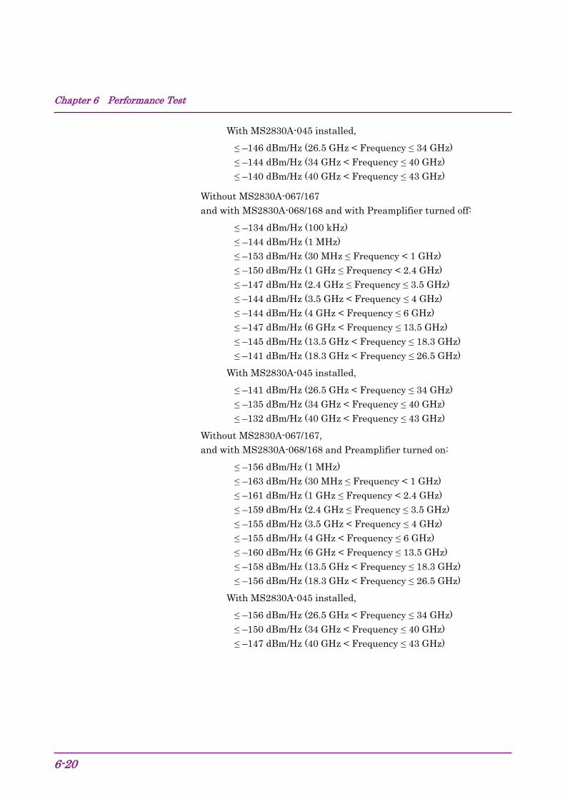
Chapter 6 Performance Test
6-20
With MS2830A-045 installed,
≤ –146 dBm/Hz (26.5 GHz < Frequency ≤ 34 GHz) ≤ –144 dBm/Hz (34 GHz < Frequency ≤ 40 GHz) ≤ –140 dBm/Hz (40 GHz < Frequency ≤ 43 GHz)
Without MS2830A-067/167 and with MS2830A-068/168 and with Preamplifier turned off:
≤ –134 dBm/Hz (100 kHz) ≤ –144 dBm/Hz (1 MHz) ≤ –153 dBm/Hz (30 MHz ≤ Frequency < 1 GHz) ≤ –150 dBm/Hz (1 GHz ≤ Frequency < 2.4 GHz) ≤ –147 dBm/Hz (2.4 GHz ≤ Frequency ≤ 3.5 GHz) ≤ –144 dBm/Hz (3.5 GHz < Frequency ≤ 4 GHz) ≤ –144 dBm/Hz (4 GHz < Frequency ≤ 6 GHz) ≤ –147 dBm/Hz (6 GHz < Frequency ≤ 13.5 GHz) ≤ –145 dBm/Hz (13.5 GHz < Frequency ≤ 18.3 GHz) ≤ –141 dBm/Hz (18.3 GHz < Frequency ≤ 26.5 GHz)
With MS2830A-045 installed,
≤ –141 dBm/Hz (26.5 GHz < Frequency ≤ 34 GHz) ≤ –135 dBm/Hz (34 GHz < Frequency ≤ 40 GHz) ≤ –132 dBm/Hz (40 GHz < Frequency ≤ 43 GHz)
Without MS2830A-067/167, and with MS2830A-068/168 and Preamplifier turned on:
≤ –156 dBm/Hz (1 MHz) ≤ –163 dBm/Hz (30 MHz ≤ Frequency < 1 GHz) ≤ –161 dBm/Hz (1 GHz ≤ Frequency < 2.4 GHz) ≤ –159 dBm/Hz (2.4 GHz ≤ Frequency ≤ 3.5 GHz) ≤ –155 dBm/Hz (3.5 GHz < Frequency ≤ 4 GHz) ≤ –155 dBm/Hz (4 GHz < Frequency ≤ 6 GHz) ≤ –160 dBm/Hz (6 GHz < Frequency ≤ 13.5 GHz) ≤ –158 dBm/Hz (13.5 GHz < Frequency ≤ 18.3 GHz) ≤ –156 dBm/Hz (18.3 GHz < Frequency ≤ 26.5 GHz)
With MS2830A-045 installed,
≤ –156 dBm/Hz (26.5 GHz < Frequency ≤ 34 GHz) ≤ –150 dBm/Hz (34 GHz < Frequency ≤ 40 GHz) ≤ –147 dBm/Hz (40 GHz < Frequency ≤ 43 GHz)

6.2 Performance Test Items
6-21
6
Perform
ance Test
With MS2830A-067/167 and without MS2830A-068/168 installed,
≤ –147 dBm/Hz (6 GHz < Frequency ≤ 13.5 GHz) ≤ –145 dBm/Hz (13.5 GHz < Frequency ≤ 18.3 GHz) ≤ –141 dBm/Hz (18.3 GHz < Frequency ≤ 26.5 GHz)
With MS2830A-045 installed,
≤ –141 dBm/Hz (26.5 GHz < Frequency ≤ 34 GHz) ≤ –135 dBm/Hz (34 GHz < Frequency ≤ 40 GHz) ≤ –132 dBm/Hz (40 GHz < Frequency ≤ 43 GHz)
With MS2830A-067/167, and with MS2830A-068/168, or with Preamplifier turned off:
≤ –143 dBm/Hz (6 GHz < Frequency ≤ 13.5 GHz) ≤ –141 dBm/Hz (13.5 GHz < Frequency ≤ 18.3 GHz) ≤ –137 dBm/Hz (18.3 GHz < Frequency ≤ 26.5 GHz)
With MS2830A-045 installed,
≤ –137 dBm/Hz (26.5 GHz < Frequency ≤ 34 GHz) ≤ –131 dBm/Hz (34 GHz < Frequency ≤ 40 GHz) ≤ –128 dBm/Hz (40 GHz < Frequency ≤ 43 GHz)
With MS2830A-067/167, and with MS2830A-068/168, or with Preamplifier turned on:
≤ –154 dBm/Hz (6 GHz < Frequency ≤ 13.5 GHz) ≤ –152 dBm/Hz (13.5 GHz < Frequency ≤ 18.3 GHz) ≤ –150 dBm/Hz (18.3 GHz < Frequency ≤ 26.5 GHz)
With MS2830A-045 installed,
≤ –150 dBm/Hz (26.5 GHz < Frequency ≤ 34 GHz) ≤ –144 dBm/Hz (34 GHz < Frequency ≤ 40 GHz) ≤ –141 dBm/Hz (40 GHz < Frequency ≤ 43 GHz)
(2) Measuring instrument for tests
Standard terminator (28N50-2) In case of MS2830A-040/041/043/044: (28K50) In case of MS2830A-045:

Chapter 6 Performance Test
6-22
(3) Setup
Figure 6.2.5-1 Display average noise level
(4) Notes on test Perform the test at an ambient temperature of 18 to 28C and after warming up for at least 30 minutes.
(5) Test procedure 1. Start the application Spectrum Analyzer of the MS2830A.
2. Press of the MS2830A.
3. Press (Preset).
4. Press and then (SIGANA All).
5. Terminate the RF input with the standard terminator.
6. Set as follows for the MS2830A (time domain mode). Center Freq 100 kHz Span 0 Hz Reference Level 100 dBm RBW 1 kHz VBW 1 Hz VBW Mode Video Attenuator 0 dB Detection Sample Sweep Time 1 s
7. Press .
8. Press (Trace-A Storage Mode) then select (Average).
9. Press to return to the original page.
10. Press (Storage Count).
11. Set the average count to 16 times.
12. Press (Single) to start averaging then wait until the sweep for an average count of 16 times is completed.
Standard Terminator
(Terminates RF Input)
MS2830A
6.2 Performance Test Items
6-23
6
Perform
ance Test
13. Using the burst average measurement function, set the Start Time and Stop Time parameters as follows and measure the level.
Start Time 100 ms Stop Time 900 ms
14. The (Burst average measurement value [dBm] 30 dB) will be the display average noise level (dBm/Hz).
15. Set the center frequency according to the Display Average Noise Level table in Appendix A, then obtain the display average noise level according to Steps 7 to 14.
16. Set this instrument as shown below, only when Preamplifier option is installed: Press to display the amplitude menu, and then press (Pre-amp) to set the pre-amplifier settings to On. Calculate the display average noise level, according to steps 11 to 15.

Chapter 6 Performance Test
6-24
6.2.6 Second harmonic wave distortion A harmonic wave is generated and displayed on the screen due to analyzer input mixer nonlinearity even when an input signal without harmonic wave distortion is applied to the spectrum analyzer.
The second harmonic wave level will be the highest among the harmonic waves displayed on this screen.
For the test method point, apply a distortion signal (at least 20 dB) lower than the internal harmonic wave of the MS2830A then measure the level difference between the fundamental wave and the second harmonic wave. In the event a low distortion signal source cannot be obtained, apply a low distortion signal to the MS2830A after passing through LPF.
(1) Test Target Standards Second harmonic wave distortion MS2830A With MS2830A-040/041/043 installed, Without MS2830A-008/108 or with Preamplifier turned off, and at Attenuator Mode = Mechanical Atten Only At mixer input level: –30 dBm:
≤ –60 dBc ( 10 MHz ≤ Input frequency ≤ 300 MHz) ≤ –65 dBc ( 300 MHz ≤ Input frequency ≤ 1 GHz) ≤ –65 dBc ( 1 GHz < Input frequency ≤ 2 GHz)
At mixer input level: –10 dBm: ≤ –70 dBc ( 2 GHz < Input frequency ≤ 3 GHz, Frequency Band
Mode: Normal)
≤ –70 dBc ( 1.75 GHz ≤ Input frequency ≤ 3 GHz, Frequency Band Mode: Spurious)
At mixer input level: –10 dBm: ≤ –70 dBc ( 3 GHz ≤ Input frequency ≤6.75 GHz)
With MS2830A-008/108 and Preamplifier turned on, and at Attenuator Mode = Mechanical Atten Only: At preamplifier input level: –45 dBm:
≤ –50 dBc ( 10 MHz ≤ Input frequency ≤ 300 MHz) ≤ –55 dBc ( 300 MHz < Input frequency ≤ 3 GHz)
With MS2830A-044/045 Without MS2830A-008/108/068/168 and without MS2830A-067/167, and at Attenuator Mode = Mechanical Atten Only:
At mixer input level –30 dBm ≤ –60 dBc (10 MHz ≤ Input frequency ≤ 300 MHz) ≤ –65 dBc (300 MHz < Input frequency ≤ 1 GHz) ≤ –65 dBc (1 GHz < Input frequency ≤ 2 GHz, Frequency Band
Mode: Normal)
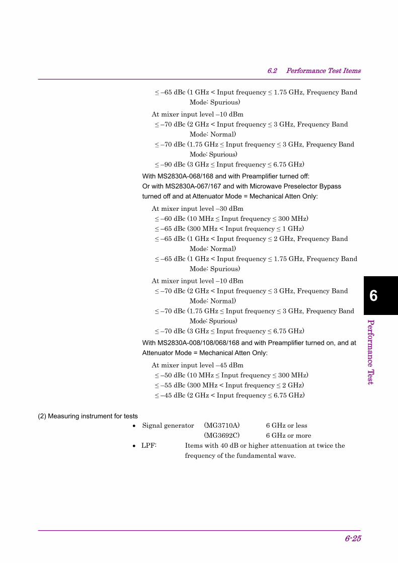
6.2 Performance Test Items
6-25
6
Perform
ance Test
≤ –65 dBc (1 GHz < Input frequency ≤ 1.75 GHz, Frequency Band Mode: Spurious)
At mixer input level –10 dBm ≤ –70 dBc (2 GHz < Input frequency ≤ 3 GHz, Frequency Band
Mode: Normal) ≤ –70 dBc (1.75 GHz ≤ Input frequency ≤ 3 GHz, Frequency Band
Mode: Spurious) ≤ –90 dBc (3 GHz ≤ Input frequency ≤ 6.75 GHz)
With MS2830A-068/168 and with Preamplifier turned off: Or with MS2830A-067/167 and with Microwave Preselector Bypass turned off and at Attenuator Mode = Mechanical Atten Only:
At mixer input level –30 dBm ≤ –60 dBc (10 MHz ≤ Input frequency ≤ 300 MHz) ≤ –65 dBc (300 MHz < Input frequency ≤ 1 GHz) ≤ –65 dBc (1 GHz < Input frequency ≤ 2 GHz, Frequency Band
Mode: Normal) ≤ –65 dBc (1 GHz < Input frequency ≤ 1.75 GHz, Frequency Band
Mode: Spurious)
At mixer input level –10 dBm ≤ –70 dBc (2 GHz < Input frequency ≤ 3 GHz, Frequency Band
Mode: Normal) ≤ –70 dBc (1.75 GHz ≤ Input frequency ≤ 3 GHz, Frequency Band
Mode: Spurious) ≤ –70 dBc (3 GHz ≤ Input frequency ≤ 6.75 GHz)
With MS2830A-008/108/068/168 and with Preamplifier turned on, and at Attenuator Mode = Mechanical Atten Only:
At mixer input level –45 dBm ≤ –50 dBc (10 MHz ≤ Input frequency ≤ 300 MHz) ≤ –55 dBc (300 MHz < Input frequency ≤ 2 GHz) ≤ –45 dBc (2 GHz < Input frequency ≤ 6.75 GHz)
(2) Measuring instrument for tests Signal generator (MG3710A) 6 GHz or less (MG3692C) 6 GHz or more
LPF: Items with 40 dB or higher attenuation at twice the frequency of the fundamental wave.
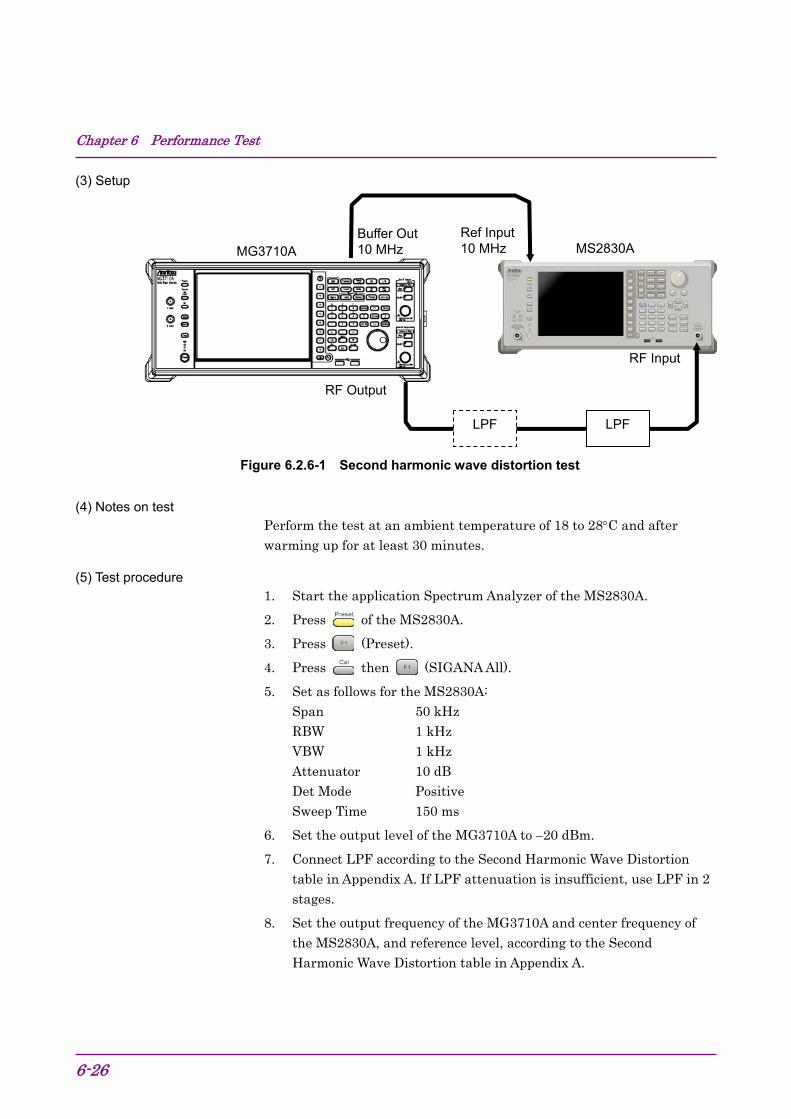
Chapter 6 Performance Test
6-26
(3) Setup
Figure 6.2.6-1 Second harmonic wave distortion test
(4) Notes on test Perform the test at an ambient temperature of 18 to 28C and after warming up for at least 30 minutes.
(5) Test procedure 1. Start the application Spectrum Analyzer of the MS2830A.
2. Press of the MS2830A.
3. Press (Preset).
4. Press then (SIGANA All).
5. Set as follows for the MS2830A: Span 50 kHz RBW 1 kHz VBW 1 kHz Attenuator 10 dB Det Mode Positive Sweep Time 150 ms
6. Set the output level of the MG3710A to 20 dBm.
7. Connect LPF according to the Second Harmonic Wave Distortion table in Appendix A. If LPF attenuation is insufficient, use LPF in 2 stages.
8. Set the output frequency of the MG3710A and center frequency of the MS2830A, and reference level, according to the Second Harmonic Wave Distortion table in Appendix A.
RF Input
RF Output
LPF
MS2830A MG3710A
LPF
Buffer Out 10 MHz
Ref Input 10 MHz

6.2 Performance Test Items
6-27
6
Perform
ance Test
9. Adjust the output level of the signal generator so as to get the peak point of the spectrum waveform into the range of 0.06 dB.
10. Press to perform a peak search. Set so as to include the signal trace peak point to the zone marker.
11. Press to display the Marker function menu, and then press (Delta) to set to the delta marker.
Figure 6.2.6-2 Fundamental wave
12. In order to display the second harmonic wave on the screen, set twice as much frequency as the center frequency. Delta marker level reading indicates the level difference between the fundamental wave and the second harmonic wave. In the event the level difference is 80 dB or higher, set the reference level to 50 dBm. Check whether the setting value of the input attenuator is 10 dB.

Chapter 6 Performance Test
6-28.
Figure 6.2.6-3 Second harmonic wave
13. Repeat Steps 7 to 12, according to the Second Harmonic Wave Distortion table in Appendix A.
14. When the Preamplifier option is installed Press and turn on the preamplifier by pressing (Pre-amp). Follow the same procedure as shown in 1 to 5 above, and then set the MG3710A output level to –35 dBm.
15. Measure the 2nd harmonic wave distortion when the preamplifier is on by using the procedure shown in 7 to 13 above.

7-1
7
Pow
er Meter
Power Meter Chapter 7
This chapter describes basic operations of the power meter functions.
7.1 Power Meter .................................................................. 7-2 7.2 Display Description ....................................................... 7-3 7.3 Function Menu .............................................................. 7-5
7.3.1 Setting the frequency........................................ 7-6 7.3.2 Level setting ..................................................... 7-7 7.3.3 Measure ............................................................ 7-9 7.3.4 Accessory ....................................................... 7-10 7.3.5 Power Meter ................................................... 7-11 7.3.6 Aperture Setting .............................................. 7-14
7.4 Initialization ................................................................. 7-15 7.4.1 Preset ............................................................. 7-15 7.4.2 Default value list ............................................. 7-15

Chapter 7 Power Meter
7-2
7.1 Power Meter You can connect a USB power sensor to the MS2830A and read the measurement values.
Preparation
For the setup procedure of the application software for this function, refer to Section 3.8 “Installing and Uninstalling” and Section 3.5 “Loading, Unloading, and Switching Applications.”
The MS2830A can accept any USB power sensor in the following table, automatically recognize its model name, and automatically set the COM Port regardless of the USB Port to which the USB power sensor is connected.
Table 7.1-1 shows the models and specifications of compatible power sensors.
Table 7.1-1 USB Power Sensors
Model Frequency Resolution Dynamic Range
MA24104A 600 MHz to 4 GHz 1 kHz +3 dBm to +51.76 dBm MA24105A 350 MHz to 4 GHz 100 kHz +3 dBm to +51.76 dBm MA24106A 50 MHz to 6 GHz 1 kHz –40 dBm to +23 dBm MA24108A 10 MHz to 8 GHz 100 kHz –40 dBm to +20 dBm MA24118A 10 MHz to 18 GHz 100 kHz –40 dBm to +20 dBm MA24126A 10 MHz to 26 GHz 100 kHz –40 dBm to +20 dBm
Follow the procedure below to select a USB power meter function:
<Procedure> 1. Plug in the USB power sensor connector to the USB port of the
MS2830A Signal Analyzer.
2. Press to display the Application Switch function menu.
3. Press the Power Meter function key.
You can select the application also by clicking the Power Meter icon on the task bar.

7.2 Display Description
7-3
7
Pow
er Meter
7.2 Display Description Press to display the Application Switch function menu. Then, select the Power Meter, and you can display the power meter application main screen and the function menu.
Figure 7.2-1 Power meter application main screen
2
6
7
8
5 43
9
11 12
1
13
10
14
15
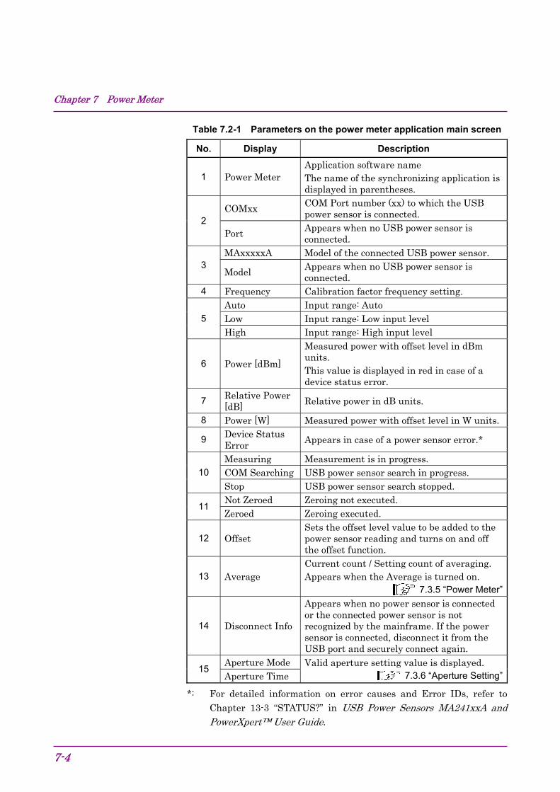
Chapter 7 Power Meter
7-4
Table 7.2-1 Parameters on the power meter application main screen
No. Display Description
1 Power Meter Application software name The name of the synchronizing application is displayed in parentheses.
2 COMxx COM Port number (xx) to which the USB
power sensor is connected.
Port Appears when no USB power sensor is connected.
3 MAxxxxxA Model of the connected USB power sensor.
Model Appears when no USB power sensor is connected.
4 Frequency Calibration factor frequency setting.
5 Auto Input range: Auto Low Input range: Low input level High Input range: High input level
6 Power [dBm]
Measured power with offset level in dBm units. This value is displayed in red in case of a device status error.
7 Relative Power [dB] Relative power in dB units.
8 Power [W] Measured power with offset level in W units.
9 Device Status Error Appears in case of a power sensor error.*
10 Measuring Measurement is in progress. COM Searching USB power sensor search in progress. Stop USB power sensor search stopped.
11 Not Zeroed Zeroing not executed. Zeroed Zeroing executed.
12 Offset Sets the offset level value to be added to the power sensor reading and turns on and off the offset function.
13 Average Current count / Setting count of averaging. Appears when the Average is turned on.
7.3.5 “Power Meter”
14 Disconnect Info
Appears when no power sensor is connected or the connected power sensor is not recognized by the mainframe. If the power sensor is connected, disconnect it from the USB port and securely connect again.
15 Aperture Mode Valid aperture setting value is displayed.
7.3.6 “Aperture Setting”Aperture Time
*: For detailed information on error causes and Error IDs, refer to Chapter 13-3 “STATUS?” in USB Power Sensors MA241xxA and PowerXpert™ User Guide.
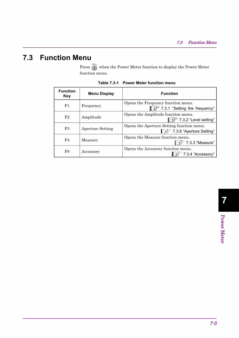
7.3 Function Menu
7-5
7
Pow
er Meter
7.3 Function Menu Press when the Power Meter function to display the Power Meter
function menu.
Table 7.3-1 Power Meter function menu
Function Key
Menu Display Function
F1 Frequency Opens the Frequency function menu.
7.3.1 “Setting the frequency”
F2 Amplitude Opens the Amplitude function menu.
7.3.2 “Level setting”
F3 Aperture Setting Opens the Aperture Setting function menu.
7.3.6 “Aperture Setting”
F4 Measure Opens the Measure function menu.
7.3.3 “Measure”
F8 Accessory Opens the Accessory function menu.
7.3.4 “Accessory”

Chapter 7 Power Meter
7-6
7.3.1 Setting the frequency In the Frequency function menu, you can set the calibration factor frequency of the USB power sensor.
Press (Frequency) in the Power Meter function menu to display the Frequency function menu.
Table 7.3.1-1 Frequency function menu
Function Key
Menu Display Function
F1 Frequency Sets the calibration factor frequency of the power sensor.
Press (Frequency) in the Frequency function menu or to display the Frequency dialog box, and then set the measurement frequency.
Table 7.3.1-2 USB Power Sensor
Model Setting range Resolution
Disconnected 10 MHz to 26 GHz 1 Hz MA24104A 600 MHz to 4 GHz 1 kHz MA24105A 350 MHz to 4 GHz 100 kHz MA24106A 50 MHz to 6 GHz 1 kHz MA24108A 10 MHz to 8 GHz 100 kHz MA24118A 10 MHz to 18 GHz 100 kHz MA24126A 10 MHz to 26 GHz 100 kHz
Note:
The values below resolutions are rounded.

7.3 Function Menu
7-7
7
Pow
er Meter
7.3.2 Level setting Press (Amplitude) or in the Power Meter function menu to display the Amplitude function menu.
Table 7.3.2-1 Amplitude function menu
Function Key
Menu Display Function
F1 Range Opens the Range function menu.
F7 Offset (On/Off)
Turns on and off the level offset function.
F8 Offset Value Sets the level offset value.
Setting the range
Press (Range) in the Amplitude function menu to display the Range function menu.
You can select the measurement range of the power sensor among Auto, High, and Low. (High and Low require manually setting.)
Note:
This parameter is always Auto when the model is MA24104A or MA24106A.
Table 7.3.2-2 Range function menu
Function Key
Menu Display Function
F1 Auto Automatic setting (Default)
F2 Low
When the model is MA24108A, MA24118A, or MA24126A: Input range: –40 dBm to –7 dBm When the model is MA24105A: Input range: +3 dBm to +38 dBm
F3 High
When the model is MA24108A, MA24118A, or MA24126A: Input range: –7 dBm to +20 dBm When the model is MA24105A: Input range: +38 dBm to +51.76 dBm

Chapter 7 Power Meter
7-8
Setting the level offset
An arbitrary offset value is added to the measurement value, and their sum is displayed.
Press (Offset) in the Amplitude function menu to turn on and off the addition of the offset value.
Offset: Level offset On Turns on the addition of the offset value. Off Turns off the addition of the offset value (Default).
Press (Offset Value) in the Amplitude function menu to display the Offset Value dialog box, and then set the offset value.
Offset Value: Setting range and minimum resolution of level offset Setting range –100.00 to 100.00 dB Resolution 0.01 dB Default 0.00 dB
When this function is used, the displayed power sensor value is offset with the value specified in the Offset Value dialog box. It is used when the path loss or gain from the MS2830A to DUT is corrected.
[Power sensor reading after offset] = [Power sensor reading] + [Offset level]
Figure 7.3.2-1 Summary of offset level
MS2830A
RF output level–45.3 dBm
(Att:1.7 dB) USB
Offset level 1.7 dB
Power sensor reading
–47 dBm
Power sensor reading (after offset) –45.3 dBm
Power sensor
DUT Path to be corrected such as cables
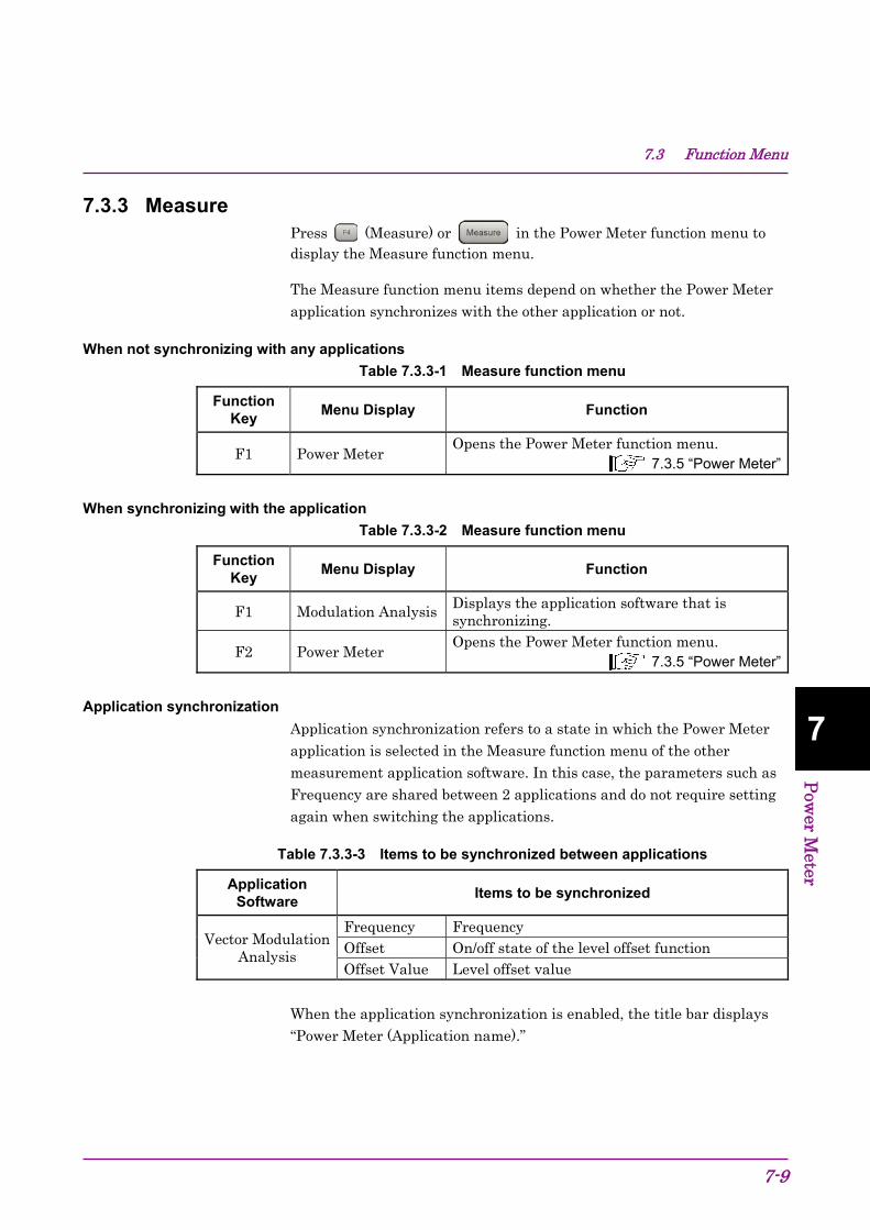
7.3 Function Menu
7-9
7
Pow
er Meter
7.3.3 Measure Press (Measure) or in the Power Meter function menu to display the Measure function menu.
The Measure function menu items depend on whether the Power Meter application synchronizes with the other application or not.
When not synchronizing with any applications
Table 7.3.3-1 Measure function menu
Function Key
Menu Display Function
F1 Power Meter Opens the Power Meter function menu.
7.3.5 “Power Meter”
When synchronizing with the application
Table 7.3.3-2 Measure function menu
Function Key
Menu Display Function
F1 Modulation Analysis Displays the application software that is synchronizing.
F2 Power Meter Opens the Power Meter function menu.
7.3.5 “Power Meter”
Application synchronization
Application synchronization refers to a state in which the Power Meter application is selected in the Measure function menu of the other measurement application software. In this case, the parameters such as Frequency are shared between 2 applications and do not require setting again when switching the applications.
Table 7.3.3-3 Items to be synchronized between applications
Application Software
Items to be synchronized
Vector Modulation Analysis
Frequency Frequency Offset On/off state of the level offset function Offset Value Level offset value
When the application synchronization is enabled, the title bar displays “Power Meter (Application name).”
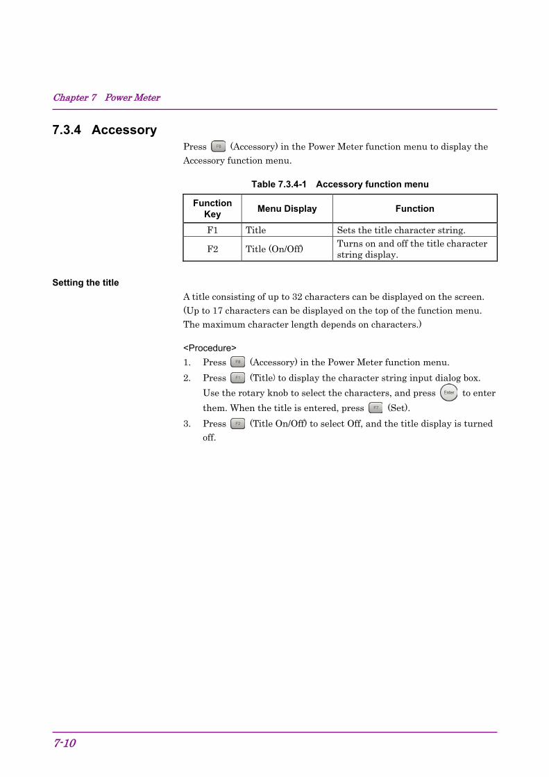
Chapter 7 Power Meter
7-10
7.3.4 Accessory Press (Accessory) in the Power Meter function menu to display the Accessory function menu.
Table 7.3.4-1 Accessory function menu
Function Key
Menu Display Function
F1 Title Sets the title character string.
F2 Title (On/Off) Turns on and off the title character string display.
Setting the title
A title consisting of up to 32 characters can be displayed on the screen. (Up to 17 characters can be displayed on the top of the function menu. The maximum character length depends on characters.)
<Procedure> 1. Press (Accessory) in the Power Meter function menu.
2. Press (Title) to display the character string input dialog box.
Use the rotary knob to select the characters, and press to enter
them. When the title is entered, press (Set).
3. Press (Title On/Off) to select Off, and the title display is turned off.
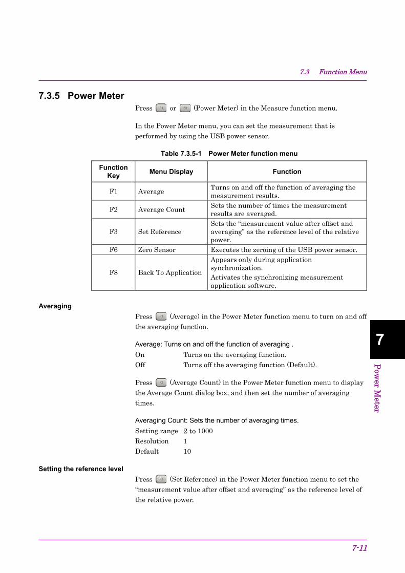
7.3 Function Menu
7-11
7
Pow
er Meter
7.3.5 Power Meter Press or (Power Meter) in the Measure function menu.
In the Power Meter menu, you can set the measurement that is performed by using the USB power sensor.
Table 7.3.5-1 Power Meter function menu
Function Key
Menu Display Function
F1 Average Turns on and off the function of averaging the measurement results.
F2 Average Count Sets the number of times the measurement results are averaged.
F3 Set Reference Sets the “measurement value after offset and averaging” as the reference level of the relative power.
F6 Zero Sensor Executes the zeroing of the USB power sensor.
F8 Back To Application
Appears only during application synchronization. Activates the synchronizing measurement application software.
Averaging
Press (Average) in the Power Meter function menu to turn on and off the averaging function.
Average: Turns on and off the function of averaging . On Turns on the averaging function. Off Turns off the averaging function (Default).
Press (Average Count) in the Power Meter function menu to display the Average Count dialog box, and then set the number of averaging times.
Averaging Count: Sets the number of averaging times. Setting range 2 to 1000 Resolution 1 Default 10
Setting the reference level
Press (Set Reference) in the Power Meter function menu to set the “measurement value after offset and averaging” as the reference level of the relative power.

Chapter 7 Power Meter
7-12
Zeroing the USB power sensor
Press (Zero Sensor) in the Power Meter function menu to execute the zeroing.
When you execute the function, a progress dialog box appears.
Please do not operate the MS2830A during the zeroing.
Figure 7.3.5-1 “Power Meter zeroing” dialog box (Progress)
If the zeroing fails, the following dialog box appears.
Figure 7.3.5-2 “Power Meter zeroing” dialog box (Zeroing failed)

7.3 Function Menu
7-13
7
Pow
er Meter
Zeroing the power sensor <Procedure> 1. Plug in the USB power sensor connector to the USB port of the
MS2830A.
2. Turn off the RF output of DUT (device under test).
3. Connect the RF Input connector of the power sensor to the RF output terminal of DUT.
CAUTION
Avoid excessive input levels when connecting the power
sensor to DUT(device under test). The power sensor may
be damaged depending on output levels of DUT.
4. Execute the Zero Sensor menu.
Activating the synchronizing application
Press (Back To Application) in the Power Meter function menu to return to the synchronizing application software.
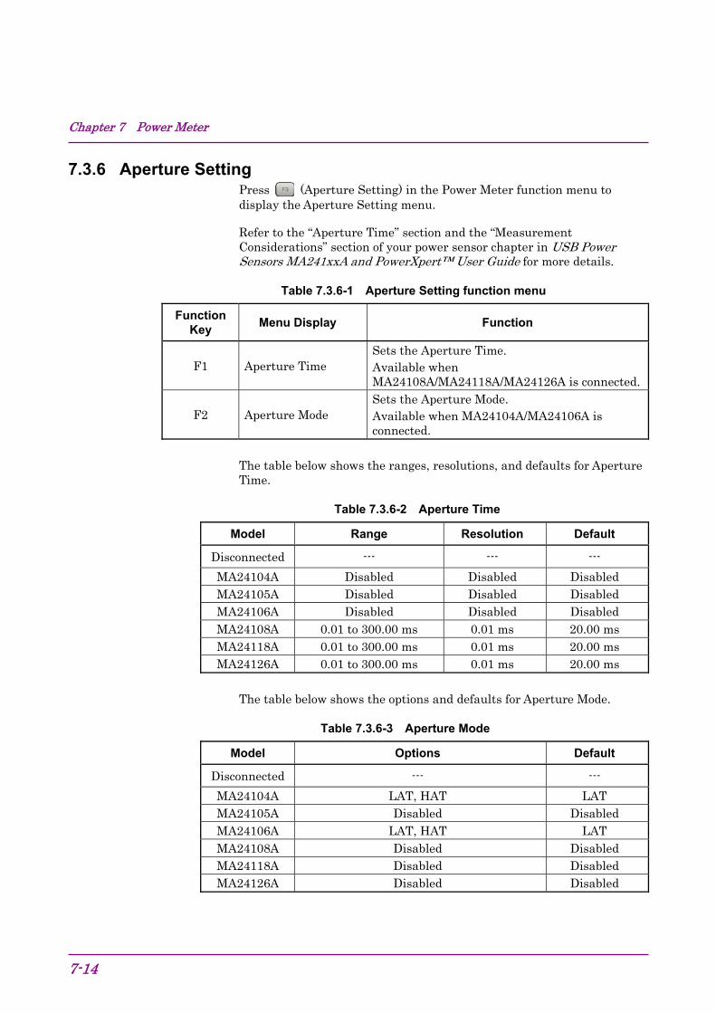
Chapter 7 Power Meter
7-14
7.3.6 Aperture Setting Press (Aperture Setting) in the Power Meter function menu to display the Aperture Setting menu.
Refer to the “Aperture Time” section and the “Measurement Considerations” section of your power sensor chapter in USB Power Sensors MA241xxA and PowerXpert™ User Guide for more details.
Table 7.3.6-1 Aperture Setting function menu
Function Key
Menu Display Function
F1 Aperture Time Sets the Aperture Time. Available when MA24108A/MA24118A/MA24126A is connected.
F2 Aperture Mode Sets the Aperture Mode. Available when MA24104A/MA24106A is connected.
The table below shows the ranges, resolutions, and defaults for Aperture Time.
Table 7.3.6-2 Aperture Time
Model Range Resolution Default
Disconnected --- --- ---
MA24104A Disabled Disabled Disabled MA24105A Disabled Disabled Disabled MA24106A Disabled Disabled Disabled MA24108A 0.01 to 300.00 ms 0.01 ms 20.00 ms MA24118A 0.01 to 300.00 ms 0.01 ms 20.00 ms MA24126A 0.01 to 300.00 ms 0.01 ms 20.00 ms
The table below shows the options and defaults for Aperture Mode.
Table 7.3.6-3 Aperture Mode
Model Options Default
Disconnected --- ---
MA24104A LAT, HAT LAT MA24105A Disabled Disabled MA24106A LAT, HAT LAT MA24108A Disabled Disabled MA24118A Disabled Disabled MA24126A Disabled Disabled

7.4 Initialization
7-15
7
Pow
er Meter
7.4 Initialization 7.4.1 Preset
Power Meter function is a kind of application. For the presetting procedure, refer to Section 3.7.1 “Preset.”
7.4.2 Default value list This section lists the default values of the Power Meter function. Frequency 1 GHz Level Offset State Off Level Offset Value 0.00 dB Average State Off Average Count 10 Reference Level 0.00 dBm Reference Level Set Off Range Auto Sensor Connected Disconnected Sensor Model Disconnected Aperture LAT (MA24104A, MA24106A) 20.00 ms (MA24108A, MA24118A, MA24126A)

Chapter 7 Power Meter
7-16.
8-1
8 B
ER Measurem
ent Function
BER Measurement Function Chapter 8 This chapter describes the operation methods for the BER measurement function of the MS2830A-026/126.
Note: This application is available only when MS2830A-026/126 is installed.
8.1 Outline of BER Measurement ....................................... 8-2 8.2 Display Description ....................................................... 8-5 8.3 BER Measurement Function Menu............................... 8-9 8.4 Connecting MS2830A-026/126 to External System ... 8-11 8.5 Performing BER Measurement ................................... 8-12 8.6 Setting Automatic Resynchronization Function .......... 8-22 8.7 Setting Input Interface ................................................. 8-27 8.8 Setting PN_Fix Pattern ............................................... 8-28 8.9 Setting User-defined Pattern ...................................... 8-34 8.10 Description of BER Measurement Operation ............. 8-42

Chapter 8 BER Measurement Function
8-2
8.1 Outline of BER Measurement The MS2830A-026/126 can measure the bit error rate (BER) of signals incoming from external systems. By pressing the Application Switch and then BER Test, the MS2830A-026/126 can be switched to BER measurement mode.
Figure 8.1-1 BER function main screen
Features of the MS2830A-026/126 BER measurement function are as listed below:
Input signals Data, Clock, Enable (Polarity inversion is enabled.)
Input level TTL level
Measurement bit rate 100 bps to 10 Mbps

8.1 Outline of BER Measurement
8-3
8 B
ER Measurem
ent Function
Measured pattern PN9, PN11, PN15, PN20, PN23, ALL0, ALL1, repetition of 01, PN9Fix, PN11Fix, PN15Fix, PN20Fix, PN23Fix, and user-defined patterns
Measurement bit count 1000 to 4294967295 bits (232 − 1 bits)
Measurement error bit count 1 to 2147483647 bits (231 − 1 bits) The maximum value that can be set as the measurement error bit count is (231 − 1 bits). If Count Mode is set to Data, however, counting of the error bit count will continue even if (231 − 1 bits) is exceeded.
Operation modes Auto Resync: On, Off Measure Mode: Continuous, Single, Endless Count Mode: Data, Error
Synchronization conditions Depends on the measurement pattern. PN 9, 11, 15, 20, 23: No errors occur for (PN stage count × 2)
consecutive bits ALL0, ALL1, repetition of 01: No errors occur for 10 consecutive bits PN_Fix pattern: See Section 8.8 User-defined pattern: No errors occur during the period that is
set for synchronization judgment

Chapter 8 BER Measurement Function
8-4
Synchronization probability The condition required for MS2830A-026/126 to synchronize with a PN signal is that no error occurs for (PN stage count × 2) consecutive bits. The table below lists the probabilities that no error will occur for (PN stage count × 2) consecutive bits for a PN signal that includes random errors. These probabilities thus can be referred to as the probabilities that the MS2830A-026/126 synchronizes with a PN signal at a certain error rate in one cycle.
Table 8.1-1 Probabilities that MS2830A-026/126 synchronizes with PN signal
PN stage counts
Error rate of PN signal (%)
PN9 PN15 PN23
10 15.0 4.2 0.79 3 57.8 40.1 24.6 1 83.5 74.0 63.0
0.1 98.2 97.0 95.5 SyncLoss detection condition The SyncLoss detection condition can be changed. However, SyncLoss detection is not executed if Auto Resync is set to Off.
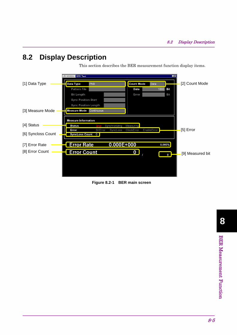
8.2 Display Description
8-5
8 B
ER Measurem
ent Function
8.2 Display Description This section describes the BER measurement function display items.
Figure 8.2-1 BER main screen
[1] Data Type
[3] Measure Mode
[2] Count Mode
[4] Status [5] Error
[6] Syncloss Count
[7] Error Rate
[8] Error Count [9] Measured bit

Chapter 8 BER Measurement Function
8-6
Table 8.2-1 Display items in BER measurement mode
No. Display Description
[1] Data Type
Displays the names of data selected on the list selection popup screen. Characters cannot be directly entered. Displays the data set on the data input screen. When User Pattern is selected in the data settings, parameters related to the loaded User Pattern are displayed. 1) Pattern File
Displays the name of the loaded User Pattern. 2) Bit Length
Displays the length (bit count) of the loaded User Pattern.
3) Sync Position Start Displays the bit at which synchronization of the User Pattern will be started.
4) Sync Position Length Displays the length (bit count) which is compared when synchronizing the User Pattern.
[2] Count Mode
Characters cannot be directly entered. The count mode set in the setup screen will be displayed. 1) Count Mode
Displays the count mode set on the input screen.
2) Bit length Displays the bit length of Data and Error set on the input screen.
[3] Measure Mode
Displays the measurement mode selected in the list selection popup screen. Characters cannot be directly entered. Displays the data set in the data setup screen.

8.2 Display Description
8-7
8 B
ER Measurem
ent Function
Table 8.2-2 Display items in Measure Information area
No. Display Description [4] Status Displays Stop, Synchronizing, and Measuring.
[5] Error
These messages light up when the following errors occur. BitError: Error bit occurrence SyncLoss: SyncLoss occurrence ClockError: Input clock signal failure EnableError: Input enable signal failure Displays OverflowDataCount or OverflowSyncLoss when the following errors occur. OverflowDataCount: The number of received
bits exceeds the maximum value (232 − 1 bits).
OverflowSyncLoss: The number of SyncLoss errors exceeds the maximum value (65535).
[6] SyncLoss Count Displays the number of SyncLoss errors.

Chapter 8 BER Measurement Function
8-8
Table 8.2-3 Error rate display
No. Display Description [7] Error Rate Displays the error rate. [8] Error Count Displays the error count. [9] Bit Displays the number of measured bits.
Error Rate display Error Rate may be displayed in either floating-point form or fixed-point percentage, which complies with the following rules:
• Floating-point display Rounding down to the 1/10000th digit from the maximum significant value, the digits up to the 1/1000th digit are displayed.
Example: For 0.00978495 → Displayed as 9.785E-003.
• Fixed-point percentage display The value is displayed in percentage. With the fourth digit of the fraction part rounded, the digits down to the third digit of the fraction part are displayed.
Example: For 0.00978495 → Displayed as 0.978%.
If BER measurement has not yet been performed, the error rate, error count, and received bits count are all displayed as 0.

8.3 BER Measurement Function Menu
8-9
8 B
ER Measurem
ent Function
8.3 BER Measurement Function Menu This section describes the main function menu on the BER measurement screen.
Figure 8.3-1 Main function menu
Page 1
F1
Page 2
F2
F3
F4
F5
F6
F7
F8
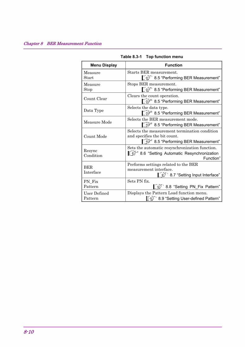
Chapter 8 BER Measurement Function
8-10
Table 8.3-1 Top function menu
Menu Display Function
Measure Start
Starts BER measurement. 8.5 “Performing BER Measurement”
Measure Stop
Stops BER measurement. 8.5 “Performing BER Measurement”
Count Clear Clears the count operation.
8.5 “Performing BER Measurement”
Data Type Selects the data type.
8.5 “Performing BER Measurement”
Measure Mode Selects the BER measurement mode.
8.5 “Performing BER Measurement”
Count Mode Selects the measurement termination condition and specifies the bit count.
8.5 “Performing BER Measurement”
Resync Condition
Sets the automatic resynchronization function. 8.6 “Setting Automatic Resynchronization
Function”
BER Interface
Performs settings related to the BER measurement interface.
8.7 “Setting Input Interface” PN_Fix Pattern
Sets PN fix. 8.8 “Setting PN_Fix Pattern”
User Defined Pattern
Displays the Pattern Load function menu. 8.9 “Setting User-defined Pattern”

8.4 Connecting MS2830A-026/126 to External System
8-11
8 B
ER Measurem
ent Function
8.4 Connecting MS2830A-026/126 to External System To perform BER measurement, signals must be input from an external system. Signals can be input from the AUX connector on the rear panel.
Details of BER signal input
The following are signal pins used for BER measurement.
• BER_CLK Inputs a clock signal that is generated in sync with data.
• BER_DATA Inputs the data signal. • BER_EN Inputs the gate (enable) signal.
Refer to Table 3.1.1-1 “AUX Connector” for details on pin assignment.
Figure 8.4-1 Input connector
If the enable signal is not used, set “Enable Active” to “Disable.”
Change the settings of the MS2830A-026/126 in accordance with the specifications of the input signal.
8.7 “Setting Input Interface”

Chapter 8 BER Measurement Function
8-12
8.5 Performing BER Measurement This function performs various BER measurement settings, and executes the measurement.
BER measurement <Procedure> 1. Input the signals from the external system according to the
instructions in Section 8.4 “Connecting MS2830A-026/126 to External System.”
2. Select the data type. Press (Data Type) to display the Data Type selection window. Move the cursor to the pattern to be used for the measurement and press (Set) to select a pattern.
Figure 8.5-1 Data Type selection window
The following patterns can be selected.
PN9, PN11, PN15, PN20, PN23, PN9Fix, PN11Fix, PN15Fix, PN20Fix, PN23Fix, ALL0, ALL1, ALT(0/1), UserDefine ALT(0/1) indicates a repetition pattern of 0 and 1. For details on PN_Fix and UserDefine, refer to the following sections respectively:
8.8 “Setting PN_Fix Pattern” 8.9 “Setting User-defined Pattern”

8.5 Performing BER Measurement
8-13
8 B
ER Measurem
ent Function
3. Select BER measure mode. Press (Measure Mode) to display the Measurement Mode selection window. Move the cursor to the desired measurement mode and press (Set) to select it.
One of the following three types can be selected for the measurement mode:
Continuous Performs the measurement continuously for the set bit count or set error bit count. Single Performs the measurement for the set bit count or set error bit count. Endless Performs the measurement for 4294967295 bits.
Figure 8.5-2 Measure Mode selection window

Chapter 8 BER Measurement Function
8-14
When “Endless” is selected for the measurement mode, the count mode (Count Mode), data bit (Data), and the display of error bit (Error) setting items is darkened.
Figure 8.5-3 When Single or Continuous is selected
Figure 8.5-4 When Endless is selected
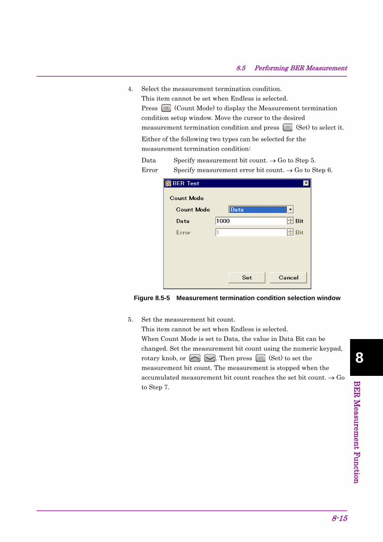
8.5 Performing BER Measurement
8-15
8 B
ER Measurem
ent Function
4. Select the measurement termination condition. This item cannot be set when Endless is selected. Press (Count Mode) to display the Measurement termination condition setup window. Move the cursor to the desired measurement termination condition and press (Set) to select it.
Either of the following two types can be selected for the measurement termination condition:
Data Specify measurement bit count. → Go to Step 5. Error Specify measurement error bit count. → Go to Step 6.
Figure 8.5-5 Measurement termination condition selection window
5. Set the measurement bit count. This item cannot be set when Endless is selected. When Count Mode is set to Data, the value in Data Bit can be changed. Set the measurement bit count using the numeric keypad, rotary knob, or . Then press (Set) to set the measurement bit count. The measurement is stopped when the accumulated measurement bit count reaches the set bit count. → Go to Step 7.

Chapter 8 BER Measurement Function
8-16
Figure 8.5-6 Measurement bit count setup window
Measurement bit count setting range: 1000 to 4294967295 bits
6. Set the measurement error bit count. This item cannot be set when Endless is selected. When Count Mode is set to Error, the value in Error Bit can be changed. Specify the measurement error bit count using the numeric keypad, rotary knob, or . Then press (Set) to count the measurement error bit count. The measurement is stopped when the accumulated measurement error bit count reaches the set bit count.
Figure 8.5-7 Measurement error bit count setup window
Measurement error bit count setting range: 1 to 2147483647 bits

8.5 Performing BER Measurement
8-17
8 B
ER Measurem
ent Function
7. Configure settings for the automatic resynchronization function. The automatic resynchronization function can be enabled/disabled and the SyncLoss error judgment condition can be set. Refer to the following section for details on the settings.
8.6 “Setting Automatic Resynchronization Function”
8. Press the (Measure Start) panel key to start BER measurement. If (Measure Stop) is pressed while BER measurement is in progress, the operation is stopped.
Operation termination conditions differ depending on the operation mode.
Press to perform BER measurement in Single measurement
mode. Press to perform BER measurement in Continuous
measurement mode. If measurement is started using these panel
keys, the BER measurement mode settings will be switched automatically.
Table 8.5-1 Operation termination conditions for BER measurement
(Single measurement mode)
Auto Resync
Count Mode On Off
Data
• The set measurement bit count is reached.
• The SyncLoss count reaches the maximum value (65535).
• The set measurement bit count is reached.
Error
• The set measurement error bit count is reached.
• The measurement bit count reaches the maximum value (232 − 1 bits).
• The SyncLoss count reaches the maximum value (65535).
• The set measurement error bit count is reached.
• The measurement bit count reaches the maximum value (232 − 1 bits).
Measurement is stopped when setting parameters (except for BER Interface).
If a condition listed in Table 8.5-1 above is met in the Continuous measurement mode, measurement is stopped once and then started again.

Chapter 8 BER Measurement Function
8-18
Measurement continues even if the view moves to another screen while BER measurement is in progress.
If the power is turned off while BER measurement is in progress, the measurement will remain stopped.
When measurement is started with a 10 Mbps signal, the upper limit of the measurement bit count is reached about 430 seconds (max.) later, and measurement is stopped.
BER measurement will be stopped if any of the following operations is performed when the Option 077/177 Analysis Bandwidth Extension to 62.5 MHz, or Option 078/178 Analysis Bandwidth Extension to 125 MHz is installed in the MS2830A.
Switching the frequency span of the signal analyzer function to 31.25 MHz or less (lower) and to 50 MHz or more (upper).
Switching the application to/from the spectrum analyzer function when the frequency span of the signal analyzer is set to 50 MHz or more.
Switching the application to/from measurement software when the frequency span of the signal analyzer is set to 50 MHz or more.

8.5 Performing BER Measurement
8-19
8 B
ER Measurem
ent Function
Display in each BER measurement mode The following figures show the difference in the measurement display among BER measurement modes. For the progress state and error rate display during measurement, see Figure 8.2-1 “BER main screen”.
Measurement Mode: Continuous The Measured result is not updated during measurement. When the measurement is completed, the measured result is updated and the measurement then starts again.
Figure 8.5-8 Measure Mode Continuous
Measure Mode: Single and Endless The received bit count, error bit count, error rate are updated as needed during measurement. When the measurement is completed, the display update is stopped.
Figure 8.5-9 Measure Mode: Single and Endless
During measurement
Measurement starts. Measurement stops.
Display is successively updated. Display is not updated.
0 clear
Count display, Error rate display
During measurement
Measurement starts. Measurement stops. Measurement restarts.
During measurement
Measurement stops.
Display is not updated. Display is not updated.
Event
Count display, Error rate display
Display is not updated.
Measurement results are updated. 0 clear Measurement results are updated.

Chapter 8 BER Measurement Function
8-20
Note: The measurement results may not be displayed correctly when “synchronizing” and “measuring” appear in the Status field alternately and repeatedly. In that case, check the settings and input signals and restart the measurement.
Count Clear operation
The operation when (Count Clear) is pressed is described below. The Count Clear operation is disabled when Continuous is selected for the measurement mode.
During measurement (Synchronizing or Measuring): The received bit count, error rate, and SyncLoss count are cleared during measurement while the synchronization state is held. Therefore, if Count Clear is executed during measurement, the received bit count at the end of measurement is smaller than the set measurement bit count. The same applies to the error bit count.
Example: Display when Count Clear is pressed when measuring 100000 bits
[1] Start the measurement.
[2] Press Count Clear. The count bit count when the switch is pressed is 35612, however the display is 0 bits.
[3] The total count bit count is 100000 bits upon measurement completion, however the display is 64388 bits (100000 − 35612).
Measurement starts. Measurement ends.
Received bit display 0 bits
Count Clear is pressed.
Measurement starts. Measurement ends.
Received bit display 35612 bits

8.5 Performing BER Measurement
8-21
8 B
ER Measurem
ent Function
Figure 8.5-10 Count Clear operation
When measurement is stopped (Stop):
The received bit count, error rate, and progress state displays are cleared.
Measurement starts. Measurement ends.
Received bit display 64388 bits

Chapter 8 BER Measurement Function
8-22
8.6 Setting Automatic Resynchronization Function This section describes the settings for the automatic resynchronization function of BER measurement.
Figure 8.6-1 Resync Condition setup screen
Setting procedure for automatic resynchronization function Press (Resync Condition) from page 2 of the main function menu to perform various settings for the automatic resynchronization function of BER measurement. Use the cursor to select the item to be set and press
(Set) to display the setting window associated with that item.
The following items can be set in this menu.
[1] Auto Resync Sets the resynchronization operation when SyncLoss occurs. On SyncLoss is detected. Resynchronization is automatically
performed when SyncLoss occurs. Off SyncLoss is not detected. The following items are enabled only when Auto Resync is set to On.
[2] Threshold Sets the SyncLoss detection conditions. When X bits out of Y bits are errors, it is judged as SyncLoss. The values of X and Y can be set here. Setting range of X (numerator): 1 to (Y/2) bits Setting range of Y (denominator): 500, 5000, 50000 bits Any value within the setting range can be set for X, while one of the three preset value should be set for Y.
[1]
[2] [3]
8.6 Setting Automatic Resynchronization Function
8-23
8 B
ER Measurem
ent Function
[3] at SyncLoss Sets whether to clear the measurement bit count when SyncLoss occurs. Count Clear Clears the measurement bit count to 0. Count Keep Retains the measurement bit count.
Details of Auto Resync The difference in operation when Auto Resync is set to On and Off is described below.
Auto Resync On If the number of occurred errors exceeds the set Threshold value when synchronization is established, it is judged as SyncLoss, the measurement is stopped, and resynchronization is executed. When Threshold is set to 200/500 (default) and the number of error bits out of 500 bits is 200 or less, measurement can be performed without SyncLoss being detected.
When measuring a signal with a high error rate, a high Threshold value, such as 200/500, can be set to suppress the detection of SyncLoss when block errors occur due to phasing.
When measuring a signal with a low error rate, a low Threshold setting, such as 50/500, can be set to enable resynchronization by quickly detecting SyncLoss when errors occur.
Auto Resync Off SyncLoss is not detected during measurement. When a signal with a high error rate is measured, the measurement is performed without interruption with this setting. Note, however, that the clock and data may be out of synchronization when the clock is not regenerated on the DUT side. In such a case, set Auto Resync to On for measurement.
The correspondence between the error rate of the measurement target and the recommended setting is shown in the table below.

Chapter 8 BER Measurement Function
8-24
Table 8.6-1 Error rate of measurement target and recommended setting
Settings
Error Rate of Measurement target
AutoResync On
AutoResync Off Threshold
value: 50/500
Threshold value:
200/500
Lower than 0.3% Optimum Applicable Applicable
0.3% or Higher Not recommended Optimum Applicable
Optimum: Most suitable setting Applicable: Measurement is possible with this setting. Not recommended: SyncLoss may occur frequently with this setting.
Reference: Default Threshold value of the MG3710A: 200/500 Threshold setting value of the MP1201C: 200/512 Default Threshold value of the MD6420A: 200/512 Threshold setting value of the MT8820C (WCDMA) BER function: 23/64
The differences between the Auto Resync operation supported in the MS2830A and the Auto Sync operation supported in the MP1201C and MD6420A are described below.
Details of Auto Resync operation The details of the Auto Resync operation supported in the MS2830A are as follows.
Auto Resync On Synchronization is executed at the start of measurement, and the measurement is started when synchronization is established. If SyncLoss is detected during measurement, resynchronization is automatically executed.
Figure 8.6-2 Auto Resync On
Measurement starts.
Synchronizing Measuring
Synchronization is established.
SyncLoss is detected.
Synchronization is established.
Resynchronizing Measuring

8.6 Setting Automatic Resynchronization Function
8-25
8 B
ER Measurem
ent Function
Auto Resync Off Synchronization is executed at the start of measurement, and the measurement is started when synchronization is established. SyncLoss is not detected during measurement.
Figure 8.6-3 Auto Resync Off
Details of Auto Sync operation The Auto Sync operation supported in the MP1201C and MD6420A is as follows.
Auto Sync On Synchronization is executed at the start of measurement, and the measurement is started when synchronization is established. If SyncLoss is detected during measurement, resynchronization is automatically executed.
Figure 8.6-4 Auto Sync On
Measurement starts.
Synchronizing Measuring
Synchronization is established.
SyncLoss is detected.
Synchronization is established.
Resynchronizing Measuring
Measurement starts.
Measuring Synchronizing
Synchronization is established.
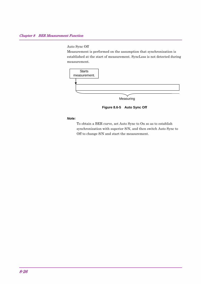
Chapter 8 BER Measurement Function
8-26
Auto Sync Off Measurement is performed on the assumption that synchronization is established at the start of measurement. SyncLoss is not detected during measurement.
Figure 8.6-5 Auto Sync Off
Note: To obtain a BER curve, set Auto Sync to On so as to establish synchronization with superior S/N, and then switch Auto Sync to Off to change S/N and start the measurement.
Starts measurement.
Measuring
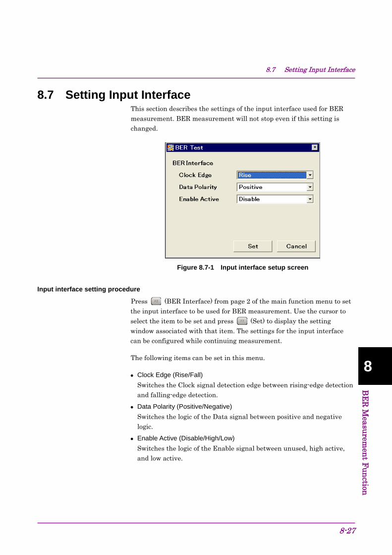
8.7 Setting Input Interface
8-27
8 B
ER Measurem
ent Function
8.7 Setting Input Interface This section describes the settings of the input interface used for BER measurement. BER measurement will not stop even if this setting is changed.
Figure 8.7-1 Input interface setup screen
Input interface setting procedure
Press (BER Interface) from page 2 of the main function menu to set the input interface to be used for BER measurement. Use the cursor to select the item to be set and press (Set) to display the setting window associated with that item. The settings for the input interface can be configured while continuing measurement.
The following items can be set in this menu.
• Clock Edge (Rise/Fall) Switches the Clock signal detection edge between rising-edge detection and falling-edge detection.
• Data Polarity (Positive/Negative) Switches the logic of the Data signal between positive and negative logic.
• Enable Active (Disable/High/Low) Switches the logic of the Enable signal between unused, high active, and low active.
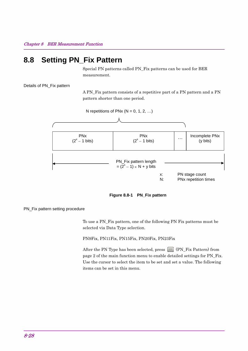
Chapter 8 BER Measurement Function
8-28
8.8 Setting PN_Fix Pattern Special PN patterns called PN_Fix patterns can be used for BER measurement.
Details of PN_Fix pattern A PN_Fix pattern consists of a repetitive part of a PN pattern and a PN pattern shorter than one period.
Figure 8.8-1 PN_Fix pattern
PN_Fix pattern setting procedure To use a PN_Fix pattern, one of the following PN Fix patterns must be selected via Data Type selection.
PN9Fix, PN11Fix, PN15Fix, PN20Fix, PN23Fix
After the PN Type has been selected, press (PN_Fix Pattern) from page 2 of the main function menu to enable detailed settings for PN_Fix. Use the cursor to select the item to be set and set a value. The following items can be set in this menu.
PNx (2x − 1 bits)
Incomplete PNx (y bits)
PNx (2x − 1 bits)
…
PN_Fix pattern length = (2x − 1) × N + y bits
x: PN stage count N: PNx repetition times
N repetitions of PNx (N = 0, 1, 2, …)

8.8 Setting PN_Fix Pattern
8-29
8 B
ER Measurem
ent Function
[1] PN Pattern Initial Sets the initial bit pattern of the PN_Fix pattern.
Figure 8.8-2 PN Pattern Initial setup screen
1. Enter the initial bit pattern of the PN_Fix pattern. Enter the initial bit pattern in binary. Use the numeric key pad (only 0 and 1) to enter numeric values.
2. The settable bit count varies depending on the selected PN type: PN9Fix: 9 bits PN11Fix: 11 bits PN15Fix: 15 bits PN20Fix: 20 bits PN23Fix: 23 bits
[2] PN_Fix Pattern Length Specifies the length of the entire PN_Fix pattern.
Figure 8.8-3 PN_Fix Pattern Length setup screen

Chapter 8 BER Measurement Function
8-30
Setting range: 96 to 134217728 bits
<Note on setting PN_Fix> When the initial value of PN_Fix is set to All0, the following signals are output: PN9, PN11, PN20: ALL0 signal PN15, PN23: ALL1 signal
Synchronization establishing condition for PN_Fix patterns
The synchronization establishing conditions for the PN_Fix pattern are described below.
In the description below, x is assumed as “PN stage count” (x = 9 for PN9).
Synchronization establishment is performed in the following three steps:
[1] Synchronization with the PN pattern is established if no error is detected for (x × 2) bits.
[2] The last bit of the PNxFix pattern is detected from the set initial bit pattern length of the PN pattern.
[3] Synchronization with the entire PN_Fix pattern is established if no error is detected for x bits beginning with the head of the PN_Fix pattern.
An example of synchronization establishment with the PN9Fix pattern is shown below.

8.8 Setting PN_Fix Pattern
8-31
8 B
ER Measurem
ent Function
Figure 8.8-4 Example of synchronization establishment operation for PN9Fix pattern
PN9 (511 bits)
PN9 (511 bits)
Incomplete PN9
(200 bits)
One cycle of PN9Fix
[1] No error detection for 18 bits (PN9 synchronization establishment condition)
PN9 (511 bits)
PN9 (511 bits)
Incomplete PN9
(200 bits)
[2] Discontinuous point detection
Discontinuous point
Incomplete PN9 (200 bits)
Discontinuous point
PN9 (511 bits)
[3] No error detection for 9 bits
PN9Fix synchronization is established.
Measurement starts.
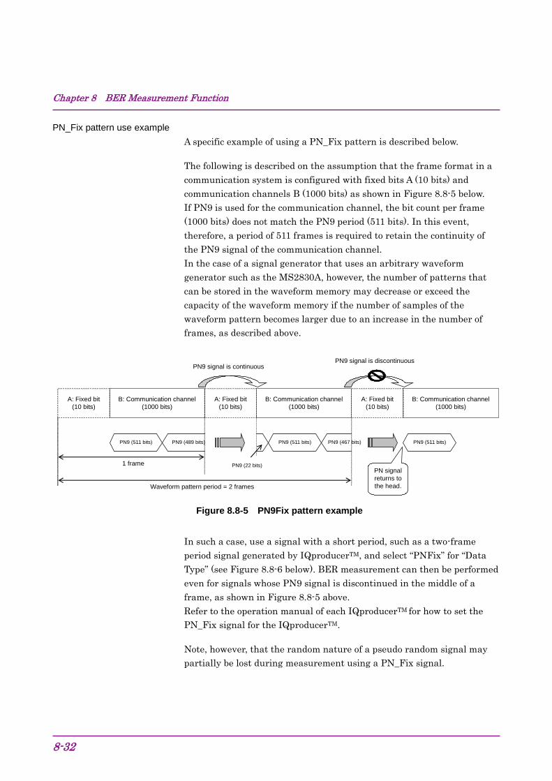
Chapter 8 BER Measurement Function
8-32
PN_Fix pattern use example A specific example of using a PN_Fix pattern is described below.
The following is described on the assumption that the frame format in a communication system is configured with fixed bits A (10 bits) and communication channels B (1000 bits) as shown in Figure 8.8-5 below. If PN9 is used for the communication channel, the bit count per frame (1000 bits) does not match the PN9 period (511 bits). In this event, therefore, a period of 511 frames is required to retain the continuity of the PN9 signal of the communication channel. In the case of a signal generator that uses an arbitrary waveform generator such as the MS2830A, however, the number of patterns that can be stored in the waveform memory may decrease or exceed the capacity of the waveform memory if the number of samples of the waveform pattern becomes larger due to an increase in the number of frames, as described above.
A: Fixed bit (10 bits)
B: Communication channel (1000 bits)
A: Fixed bit (10 bits)
B: Communication channel (1000 bits)
PN9 (511 bits) PN9 (489 bits)
PN9 (22 bits)
PN9 (511 bits) PN9 (467 bits)
PN9 signal is continuous
A: Fixed bit (10 bits)
B: Communication channel (1000 bits)
PN9 (511 bits)
PN9 signal is discontinuous
Waveform pattern period = 2 frames
1 frame PN signal returns to the head.
Figure 8.8-5 PN9Fix pattern example
In such a case, use a signal with a short period, such as a two-frame period signal generated by IQproducerTM, and select “PNFix” for “Data Type” (see Figure 8.8-6 below). BER measurement can then be performed even for signals whose PN9 signal is discontinued in the middle of a frame, as shown in Figure 8.8-5 above. Refer to the operation manual of each IQproducerTM for how to set the PN_Fix signal for the IQproducerTM.
Note, however, that the random nature of a pseudo random signal may partially be lost during measurement using a PN_Fix signal.

8.8 Setting PN_Fix Pattern
8-33
8 B
ER Measurem
ent Function
Figure 8.8-6 BER measurement using PN_Fix data
DUT
Clock,Data,Enable
Waveform pattern (PN_Fix data) RF signal
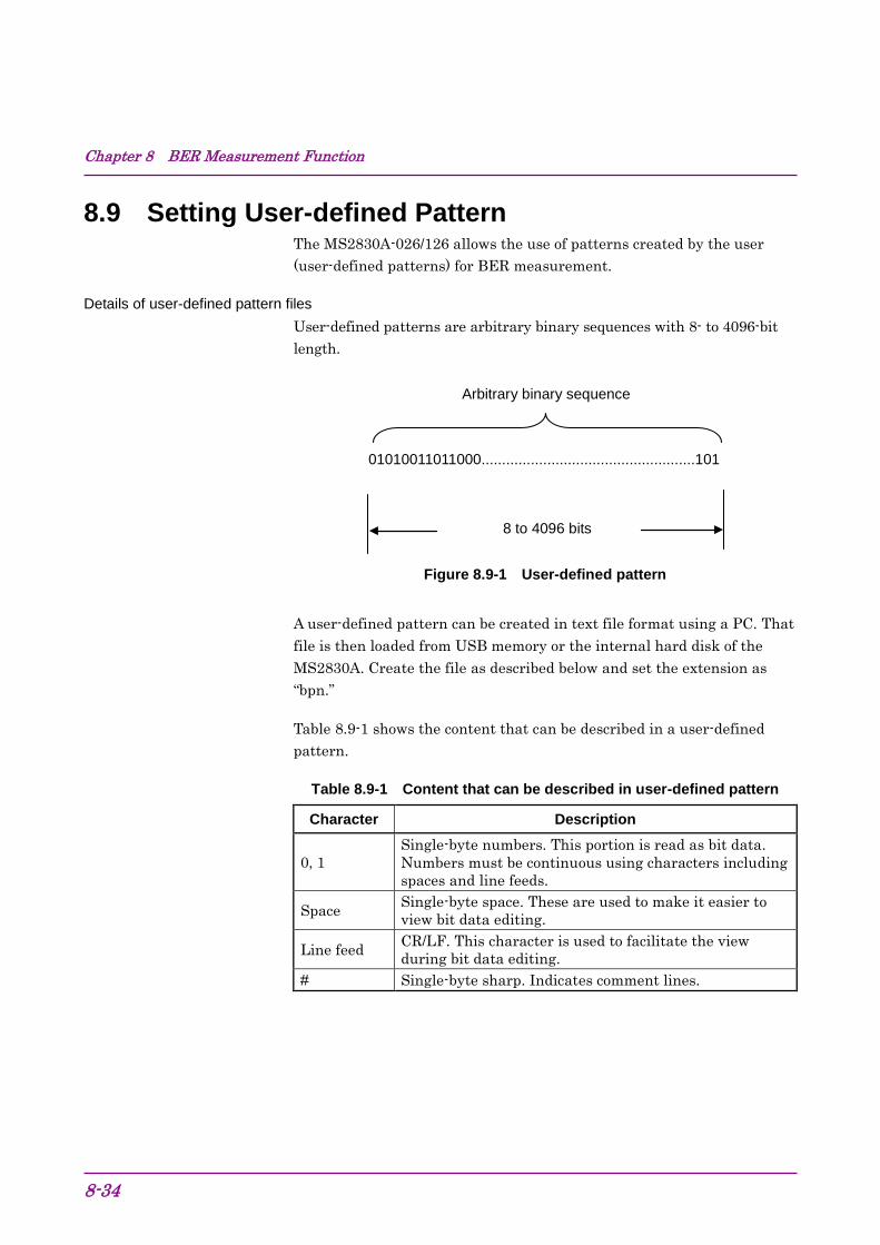
Chapter 8 BER Measurement Function
8-34
8.9 Setting User-defined Pattern The MS2830A-026/126 allows the use of patterns created by the user (user-defined patterns) for BER measurement.
Details of user-defined pattern files User-defined patterns are arbitrary binary sequences with 8- to 4096-bit length.
Figure 8.9-1 User-defined pattern
A user-defined pattern can be created in text file format using a PC. That file is then loaded from USB memory or the internal hard disk of the MS2830A. Create the file as described below and set the extension as “bpn.”
Table 8.9-1 shows the content that can be described in a user-defined pattern.
Table 8.9-1 Content that can be described in user-defined pattern
Character Description
0, 1 Single-byte numbers. This portion is read as bit data. Numbers must be continuous using characters including spaces and line feeds.
Space Single-byte space. These are used to make it easier to view bit data editing.
Line feed CR/LF. This character is used to facilitate the view during bit data editing.
# Single-byte sharp. Indicates comment lines.
01010011011000....................................................101
8 to 4096 bits
Arbitrary binary sequence

8.9 Setting User-defined Pattern
8-35
8 B
ER Measurem
ent Function
The following shows examples of file content that can be loaded.
Example 1: #20070216 Marked by Anritsu Co. 0010 0111 0110 0011 0000 1111 0101
Example 2: #UserPattern Start 0000 0000 1111 1111 #mark001 0101 0101 #mark002 1111 1111 0000 0000

Chapter 8 BER Measurement Function
8-36
Displaying user-defined patterns To use a user-defined pattern, select UserDefine for Data Type. The parameters for the loaded user-defined pattern will be displayed on the main screen. Blanks will be displayed if no user-defined pattern is loaded.
Figure 8.9-2 User-defined pattern parameter display
[1] Pattern File Displays the name of the loaded user pattern.
[2] Bit Length Displays the length (number of bits) of the loaded user pattern.
[3] Sync Position Start Displays the bit at which synchronizing the user pattern is to be started.
[4] Sync Position Length Displays a length (number of bits) to be compared with when synchronizing a user pattern.
[1] Pattern File [2] Bit Length [3] Sync Position Start [4] Sync Position Length

8.9 Setting User-defined Pattern
8-37
8 B
ER Measurem
ent Function
User-defined pattern function menu Select User Pattern for Data Type and press (User Defined Pattern) from page 2 of the main function menu to display the user-defined pattern file function menu.
Figure 8.9-3 User-defined pattern function menu
Table 8.9-2 User-defined pattern function menu
Menu Display Function
User Pattern Detail
Performs settings related for synchronizing loaded user-defined patterns.
Load User Pattern
Loads user-defined patterns from the USB memory or the internal hard disk of the MS2830A.
Device Selects the media among the USB memory and internal hard disk from which user-defined patterns are to be loaded.
F1
F2
F3
F4
F5
F6
F7
F8
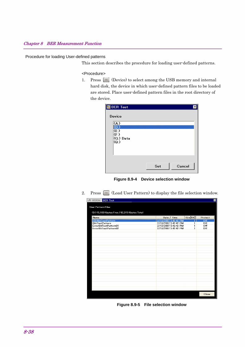
Chapter 8 BER Measurement Function
8-38
Procedure for loading User-defined patterns This section describes the procedure for loading user-defined patterns.
<Procedure> 1. Press (Device) to select among the USB memory and internal
hard disk, the device in which user-defined pattern files to be loaded are stored. Place user-defined pattern files in the root directory of the device.
Figure 8.9-4 Device selection window
2. Press (Load User Pattern) to display the file selection window.
Figure 8.9-5 File selection window
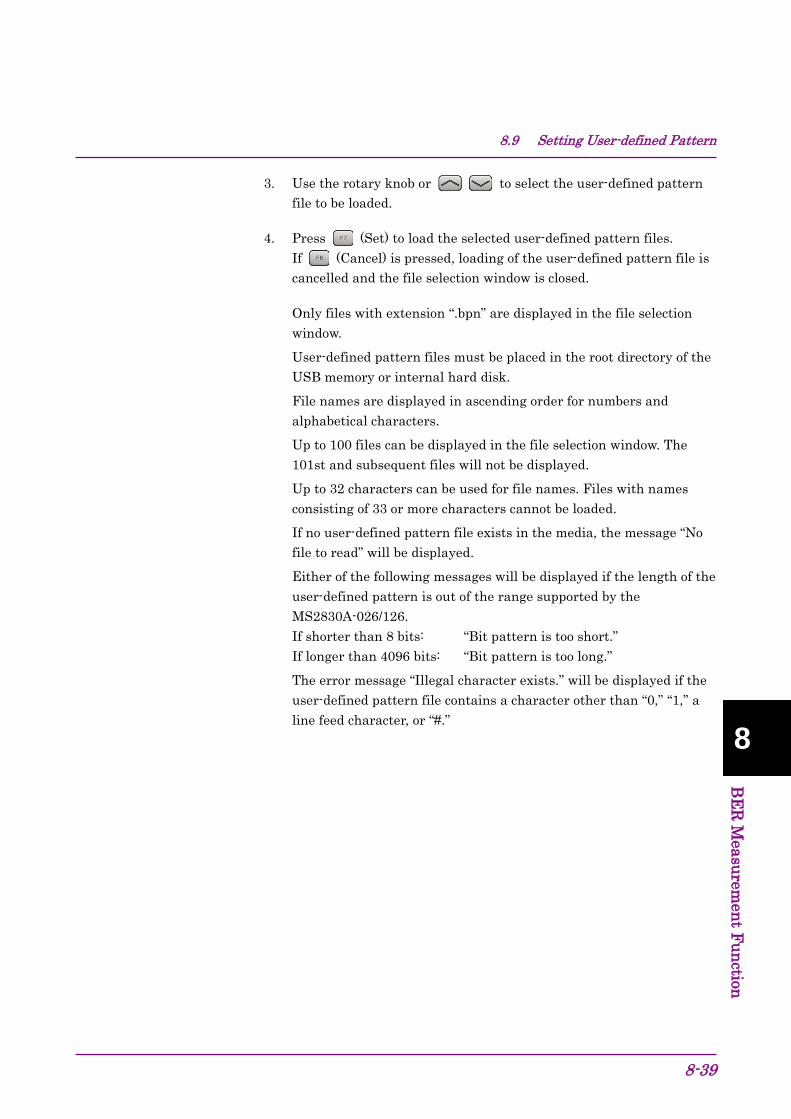
8.9 Setting User-defined Pattern
8-39
8 B
ER Measurem
ent Function
3. Use the rotary knob or to select the user-defined pattern file to be loaded.
4. Press (Set) to load the selected user-defined pattern files. If (Cancel) is pressed, loading of the user-defined pattern file is cancelled and the file selection window is closed.
Only files with extension “.bpn” are displayed in the file selection window.
User-defined pattern files must be placed in the root directory of the USB memory or internal hard disk.
File names are displayed in ascending order for numbers and alphabetical characters.
Up to 100 files can be displayed in the file selection window. The 101st and subsequent files will not be displayed.
Up to 32 characters can be used for file names. Files with names consisting of 33 or more characters cannot be loaded.
If no user-defined pattern file exists in the media, the message “No file to read” will be displayed.
Either of the following messages will be displayed if the length of the user-defined pattern is out of the range supported by the MS2830A-026/126. If shorter than 8 bits: “Bit pattern is too short.” If longer than 4096 bits: “Bit pattern is too long.”
The error message “Illegal character exists.” will be displayed if the user-defined pattern file contains a character other than “0,” “1,” a line feed character, or “#.”

Chapter 8 BER Measurement Function
8-40
Synchronization establishing condition setting for user-defined patterns When the user-defined pattern is loaded, set the conditions for synchronization establishment. Set the start bit and the length of the section to be used for judging the synchronization establishment. If no error is detected in the specified part, it is judged that synchronization is established.
Figure 8.9-6 Setting method for section judged for synchronization establishment
Example: Setting synchronization for a user-defined pattern <Procedure> 1. Press (User Pattern Detail) from the user-defined pattern
function menu to display the User Pattern Detail setting window.
Figure 8.9-7 User pattern Detail setting window
2. Move the cursor to Sync Position Start and use the numeric key pad, rotary knob, or to set the start bit of the section judged for synchronization establishment.
Range: 1 to the length of the user-defined pattern
0101001101100001010101110000.....................101
Section for judgment of synchronization establishment
<1> Start bit
<2> Length

8.9 Setting User-defined Pattern
8-41
8 B
ER Measurem
ent Function
3. Move the cursor to Sync Position Length and use the numeric key pad, rotary knob, or to set the length of the section judged for synchronization establishment.
Range: 8 to 1024
Chapter 8 BER Measurement Function
8-42
8.10 Description of BER Measurement Operation This section describes the BER measurement operation, from synchronization to measurement termination.
When Auto Resync is set to Off The following flowchart summarizes BER measurement operation when Auto Resync is set to Off. In this mode, the error rate is checked immediately after synchronization in order to judge whether synchronization is correctly established. If the error rate is 30% or higher, it is judged as a synchronization failure, and re-synchronization is executed.

8.10 Description of BER Measurement Operation
8-43
8 B
ER Measurem
ent Function
Figure 8.10-1 When Auto Resync is set to Off
Establishing synchronization*1
Synchronization check is passed
Synchronization failure
Single or Endless
Continuous
Display: Synchronization
Condition is met (Terminating)
Condition is not met (Continuing)
Synchronization
Count operation
Measurement stop
Start of BER measurement
End of BER measurement
Synchronization check*2
Measure Mode check
Termination condition check*3
Display: Measuring
Display: Stop
Chapter 8 BER Measurement Function
8-44
*1: The error rate is not checked if the measurement is terminated with a measurement bit count of less than 1000 bits. The measured values may be incorrect in this event.
*2: If the error rate when the measurement bit count reaches 1000 bits is 30% or higher, it is judged as a synchronization failure.
*3: The measurement termination conditions are as follows:
• The accumulated measurement bit count or measurement error bit count reaches the set bit count.
• The measurement bit count exceeds the maximum value. • The number of SyncLoss errors exceeds the maximum value.

8.10 Description of BER Measurement Operation
8-45
8 B
ER Measurem
ent Function
When Auto Resync is set to On The following flowchart summarizes the BER measurement operation when Auto Resync is set to On. In this mode, resynchronization is automatically executed when SyncLoss occurs.

Chapter 8 BER Measurement Function
8-46
Figure 8.10-2 When Auto Resync is set to On
Synchronization
Count operation
Measurement stop
Establishing synchronization
Single or Endless
Continuous
Display: Stop
Start of BER measurement
End of BER measurement
Termination condition check*3
Condition is met. (Terminating)
Condition is not met (Continuing)
Reception of bits required for SyncLoss condition check*1
SyncLoss*2
OK
Display: Synchronization
Display: Measuring
SyncLoss check
Measure Mode check
8.10 Description of BER Measurement Operation
8-47
8 B
ER Measurem
ent Function
*1: The SyncLoss condition check is not executed until the number of received bits reaches the number of bits set as the denominator of the SyncLoss threshold set in [Threshold] on the Resync Condition Setup screen. Therefore, it may take some time to start the count operation after synchronization is established.
*2: Operation after SyncLoss occurrence is performed according to the setting specified in “at SyncLoss” on the Resync Condition Setup screen.
*3: The measurement termination conditions are as follows:
• The accumulated measurement bit count or measurement error bit count reaches the set bit count.
• The measurement bit count exceeds the maximum value. • The number of SyncLoss errors exceeds the maximum value.

Chapter 8 BER Measurement Function
8-48.

9-1
9
Main
tenan
ce
Maintenance Chapter 9
This chapter describes cautions related to daily maintenance, storage, and shipping of the MS2830A, as well as the calibration procedure to be used as preventive maintenance.
9.1 Daily Maintenance and Storage .................................... 9-2 9.1.1 Daily maintenance ............................................ 9-2 9.1.2 Cautions on storage MS2830A for
extended period ................................................ 9-3 9.1.3 Storing USB memory stick ............................... 9-3
9.2 Repackaging and transporting when returning product ........... 9-4 9.2.1 Repackaging ..................................................... 9-4 9.2.2 Transporting ..................................................... 9-4
9.3 Calibration ....................................................................... 9-5 9.3.1 Calibration ........................................................ 9-5 9.3.2 Instruments used for calibrating MS2830A ...... 9-5 9.3.3 Calibrating frequencies using
frequency counter ............................................. 9-6

Chapter 9 Maintenance
9-2
9.1 Daily Maintenance and Storage 9.1.1 Daily maintenance
Before daily maintenance of the MS2830A, be sure to turn the power off and unplug it from the AC outlet.
Panel surface dirt When surface dirt is noticeable, after the MS2830A has been used in a dusty environment, or when the MS2830A has not been used for an extended period of time, wipe its surface with a cloth moistened in detergent and wrung enough.
Screen surface dirt If the screen surface is dirty, first wipe it dry with a soft cloth. If the dirt persists, wipe the surface gently with a cloth dipped in detergent and wrung enough.
Loose screws Use a Phillips screwdriver to tighten screws.

9.1 Daily Maintenance and Storage
9-3
9
Main
tenan
ce
9.1.2 Cautions on storage MS2830A for extended period Wipe off dust, fingerprint marks, stains, spots, etc. from the surface of the MS2830A before storing it. Avoid storing the MS2830A in these places:
Places that are exposed to direct sunlight
Dusty places
Damp places where condensation may occur on the MS2830A surface
Places where there the MS2830A may be corroded by active gases
Places where the MS2830A may be oxidized
Places having temperatures and relative humidity in the following ranges: Temperature: 20C or lower, or 60C or higher Humidity: 90% or higher
Recommended storage conditions It is recommended that the MS2830A be stored in a place that meets the ambient conditions suggested above, plus the following conditions, if it is not to be used for a long period of time:
Temperature: 5C to 45C
Humidity: 40% to 80%
Little temperature and humidity fluctuations within one day
9.1.3 Storing USB memory stick Store the USB memory stick at temperatures between 4°C and 53°C and relative humidity between 8% and 90% (no condensation). Avoid storing the USB memory stick in places that are:
Dusty or damp
Close to magnetized items
Exposed to direct sunlight
Close to heat sources
Chapter 9 Maintenance
9-4
9.2 Repackaging and transporting when returning product The following describes cautions on transporting the MS2830A.
9.2.1 Repackaging Repack the MS2830A in the packing material (box) in which it had been delivered. If the packing material has been scrapped or damaged, repack the MS2830A in the following manner:
1. Wrap the MS2830A in plastic or a similar material.
2. Procure a corrugated cardboard, wooden, or aluminum box large enough to pack in cushioning material around the MS2830A.
3. Place the MS2830A into the box. Then, pack in the cushioning material around the MS2830A so that the MS2830A does not move around in the box.
4. Secure the outside of the box with packaging cord, adhesive tape, bands, or other such implements.
9.2.2 Transporting Avoiding as much vibrations as possible and satisfying the recommended storage conditions is recommended for transporting.

9.3 Calibration
9-5
9
Main
tenan
ce
9.3 Calibration 9.3.1 Calibration
Perform calibration as preventive maintenance to keep the MS2830A's performance from becoming degraded. Even if the MS2830A is functioning normally, calibrate it periodically to maintain its performance.
Calibrating the MS2830A once or twice a year is recommended. If the MS2830A fails to meet specifications after calibration, contact an Anritsu Service and Sales office. Contact information can be found on the last page of the printed version of this manual, and is available in a separate file on the PDF version.
CAUTION Before performing the calibration, allow the MS2830A and
the equipment used for the performance test to warm up at
least 30 minutes to allow them to fully stabilize. For
optimal measuring accuracy, run the MS2830A at the
temperature of 23±5°C), with low AC voltage fluctuation
(100 to 120 Vac or 200 to 240 Vac), in an environment free
from noise, vibration, dust, moisture, and other harmful
ambient conditions.
9.3.2 Instruments used for calibrating MS2830A Table 9.3.2-1 lists the measuring instruments used to calibrate the MS2830A.
Table 9.3.2-1 List of measuring instruments for calibration
Name of Recommended
Device Required Performance Calibration Items
Frequency counter Capable of 1 GHz measurement Reference oscillator frequency accuracy
Signal generator Capable of outputting 1 GHz signal (Resolution: 0.01 Hz or higher)
Reference oscillator frequency accuracy
Frequency standard device
Standard radio receiver or device with equivalent capability (Accuracy: 1 1011 order or better)
Reference oscillator frequency accuracy
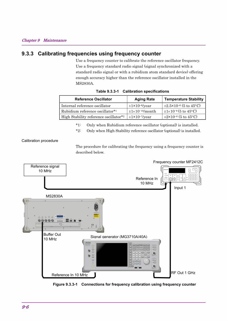
Chapter 9 Maintenance
9-6
9.3.3 Calibrating frequencies using frequency counter Use a frequency counter to calibrate the reference oscillator frequency. Use a frequency standard radio signal (signal synchronized with a standard radio signal or with a rubidium atom standard device) offering enough accuracy higher than the reference oscillator installed in the MS2830A.
Table 9.3.3-1 Calibration specifications
Reference Oscillator Aging Rate Temperature Stability
Internal reference oscillator ±1×10⁻⁶/year ±2.5×10⁻⁶ (5 to 45C) Rubidium reference oscillator*1 11010/month 1109 (5 to 45C) High Stability reference oscillator*2 ±1×10⁻⁷/year ±2×10⁻⁸ (5 to 45C)
*1: Only when Rubidium reference oscillator (optional) is installed. *2: Only when High Stability reference oscillator (optional) is installed.
Calibration procedure The procedure for calibrating the frequency using a frequency counter is described below.
Figure 9.3.3-1 Connections for frequency calibration using frequency counter
Reference signal 10 MHz
Buffer Out 10 MHz
RF Out 1 GHz Reference In 10 MHz
MS2830A
Reference In10 MHz
Input 1
Frequency counter MF2412C
Signal generator (MG3710A/40A)

9.3 Calibration
9-7
9
Main
tenan
ce
1. Connect a 10 MHz signal output from the frequency standard device to the reference signal input connector (Reference In) of frequency counter.
2. Connect the reference signal output (Buffer Out) located on the rear panel of the MS2830A to the reference signal input connector (Reference In) of Signal Generator.
3. Connect the RF output connector 1 of signal generator to input 1 connector of the frequency counter.
4. Set the frequency of signal generator to 1 GHz for output.
5. Set the measurement time of the frequency counter to 10 s and measure frequency.
When the frequency does not match, the MS2830A’s reference oscillator should be adjusted.*
6. To achieve synchronization, start the Signal Analyzer or the Spectrum Analyzer application. Then press (Accessory) from the Main function menu of the signal analyzer or the spectrum analyzer.
7. Press (Reference Clock) from the Accessory function menu.
8. From the Reference Clock function menu, press (Reference Clock) then input adjustment values. The adjustment value can be set from 0 to 1023.
9. Adjust so that frequency error is as small as possible.
*: Perform a similar measurement after System Recovery. Re-adjustment is required when the frequency does not match.

Chapter 9 Maintenance
9-8.

A-1
Ap
pen
dix
Appen
dix A
Appendix A Performance Test Result Form
Performance Test Result Form
Test Location
Report No.
Date
Test person in charge
Equipment Name: MS2830A Signal Analyzer
Serial No. Ambient temperature
C
Power frequency
Relative humidity
%
Remarks
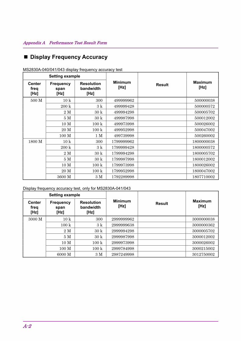
Appendix A Performance Test Result Form
A-2
Display Frequency Accuracy
MS2830A-040/041/043 display frequency accuracy test Setting example
Minimum [Hz]
Result Maximum
[Hz] Center
freq [Hz]
Frequency span [Hz]
Resolution bandwidth
[Hz]
500 M 10 k 300 499999962 500000038 200 k 3 k 499999428 500000572
2 M 30 k 499994298 5000057025 M 30 k 499987998 500012002
10 M 100 k 499973998 50002600220 M 100 k 499952998 500047002
100 M 1 M 499739998 5002600021800 M 10 k 300 1799999962 1800000038
200 k 3 k 1799999428 18000005722 M 30 k 1799994298 18000057025 M 30 k 1799987998 1800012002
10 M 100 k 1799973998 180002600220 M 100 k 1799952998 1800047002
3600 M 3 M 1792289998 1807710002
Display frequency accuracy test, only for MS2830A-041/043
Setting example
Minimum [Hz]
Result Maximum
[Hz] Center
freq [Hz]
Frequency span [Hz]
Resolution bandwidth
[Hz]
3000 M 10 k 300 2999999962 3000000038100 k 3 k 2999999638 3000000362
2 M 30 k 2999994298 30000057025 M 30 k 2999987998 3000012002
10 M 100 k 2999973998 3000026002100 M 100 k 2999784998 3000215002
6000 M 3 M 2987249998 3012750002
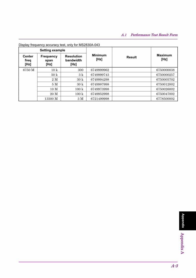
A.1 Performance Test Result Form
A-3
Ap
pen
dix
Appen
dix A
Display frequency accuracy test, only for MS2830A-043 Setting example
Minimum [Hz]
Result Maximum
[Hz] Center
freq [Hz]
Frequency span [Hz]
Resolution bandwidth
[Hz]
6750 M 10 k 300 6749999962 675000003850 k 3 k 6749999743 67500002572 M 30 k 6749994298 67500057025 M 30 k 6749987998 6750012002
10 M 100 k 6749973998 675002600220 M 100 k 6749952998 6750047002
13500 M 3 M 6721499998 6778500002

Appendix A Performance Test Result Form
A-4
Display frequency accuracy test, only for MS2830A-044/045 Setting example
Minimum [Hz]
Result Maximum
[Hz] Center
freq [Hz]
Frequency span [Hz]
Resolution bandwidth
[Hz]
500 M 10 k 300 499999962 500000038 200 k 3 k 499999428 500000572
2 M 30 k 499994298 5000057025 M 30 k 499987998 500012002
10 M 100 k 499973998 50002600220 M 100 k 499952998 500047002
100 M 1 M 499739998 5002600022000 M 10 k 300 1999999962 2000000038
200 k 3 k 1999999428 20000005722 M 30 k 1999994298 20000057025 M 30 k 1999987998 2000012002
10 M 100 k 1999973998 200002600220 M 100 k 1999952998 2000047002
3600 M 3 M 1992289998 20077100027200 M 10 k 300 7199999962 7200000038
100 k 3 k 7199999638 72000003622 M 30 k 7199994298 72000057025 M 30 k 7199987998 7200012002
10 M 100 k 7199973998 7200026002100 M 100 k 7199784998 7200215002
4000 M 3 M 7191449998 720855000214450 M 10 k 300 14449999960 14450000040
50 k 3 k 14449999741 144500002592 M 30 k 14449994296 144500057045 M 30 k 14449987996 14450012004
10 M 100 k 14449973996 1445002600420 M 100 k 14449952996 14450047004
7900 M 3 M 14433259996 14466740004
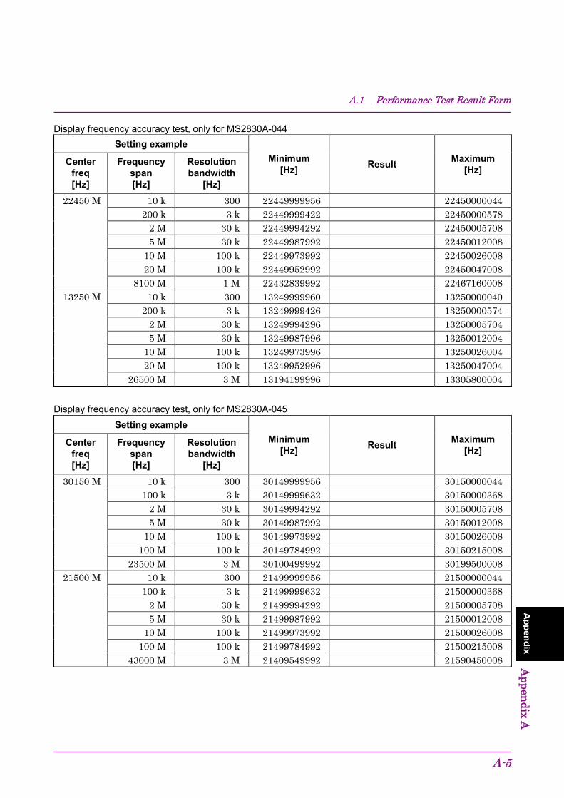
A.1 Performance Test Result Form
A-5
Ap
pen
dix
Appen
dix A
Display frequency accuracy test, only for MS2830A-044 Setting example
Minimum [Hz]
Result Maximum
[Hz] Center
freq [Hz]
Frequency span [Hz]
Resolution bandwidth
[Hz]
22450 M 10 k 300 22449999956 22450000044200 k 3 k 22449999422 22450000578
2 M 30 k 22449994292 224500057085 M 30 k 22449987992 22450012008
10 M 100 k 22449973992 2245002600820 M 100 k 22449952992 22450047008
8100 M 1 M 22432839992 2246716000813250 M 10 k 300 13249999960 13250000040
200 k 3 k 13249999426 132500005742 M 30 k 13249994296 132500057045 M 30 k 13249987996 13250012004
10 M 100 k 13249973996 1325002600420 M 100 k 13249952996 13250047004
26500 M 3 M 13194199996 13305800004
Display frequency accuracy test, only for MS2830A-045 Setting example
Minimum [Hz]
Result Maximum
[Hz] Center
freq [Hz]
Frequency span [Hz]
Resolution bandwidth
[Hz]
30150 M 10 k 300 30149999956 30150000044100 k 3 k 30149999632 30150000368
2 M 30 k 30149994292 301500057085 M 30 k 30149987992 30150012008
10 M 100 k 30149973992 30150026008100 M 100 k 30149784992 30150215008
23500 M 3 M 30100499992 3019950000821500 M 10 k 300 21499999956 21500000044
100 k 3 k 21499999632 215000003682 M 30 k 21499994292 215000057085 M 30 k 21499987992 21500012008
10 M 100 k 21499973992 21500026008100 M 100 k 21499784992 21500215008
43000 M 3 M 21409549992 21590450008

Appendix A Performance Test Result Form
A-6
Frequency Span Display Accuracy
MS2830A-040/041/043 frequency span display accuracy test
Settings for MS2830A
Min[%]
Measurement Results
Max[%] Center
Freq [Hz]
RBW [Hz]
Frequency Span [Hz]
Signal Generator (f2 f1) / 0.8
/ SPAN 100 100 [%]
f1 [Hz] f2 [Hz]
1800 M 300 10 k 1799996000 1800004000 –0.2 +0.2 30 k 1 M 1799600000 1800400000 –0.2 +0.2
100 k 10 M 1796000000 1804000000 –0.2 +0.2 1 M 100 M 1760000000 1840000000 –0.2 +0.2 3 M 3600 M 360000000 3240000000 –0.2 +0.2
3000 M (MS2830A -041/043 only)
300 10 k 2999996000 3000004000 –0.2 +0.2 30 k 1 M 2999600000 3000400000 –0.2 +0.2
100 k 1 0 M 2996000000 3004000000 –0.2 +0.2 1 M 100 M 2960000000 3040000000 –0.2 +0.2 3 M 6000 M 600000000 5400000000 –0.2 +0.2
6750 M (MS2830A-043 only)
3 M 13500 M 1350000000 12150000000 –0.2 +0.2
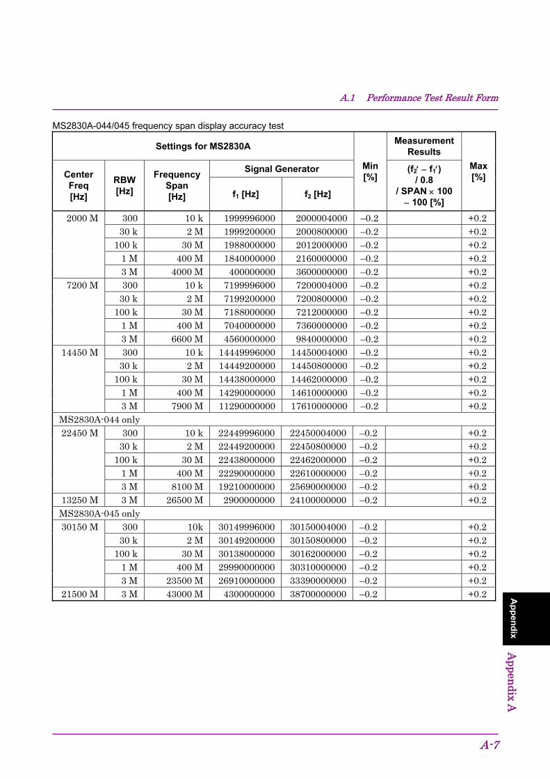
A.1 Performance Test Result Form
A-7
Ap
pen
dix
Appen
dix A
MS2830A-044/045 frequency span display accuracy test
Settings for MS2830A
Min[%]
Measurement Results
Max[%] Center
Freq [Hz]
RBW [Hz]
Frequency Span [Hz]
Signal Generator (f2 f1) / 0.8
/ SPAN 100 100 [%]
f1 [Hz] f2 [Hz]
2000 M 300 10 k 1999996000 2000004000 –0.2 +0.2 30 k 2 M 1999200000 2000800000 –0.2 +0.2
100 k 30 M 1988000000 2012000000 –0.2 +0.2 1 M 400 M 1840000000 2160000000 –0.2 +0.2 3 M 4000 M 400000000 3600000000 –0.2 +0.2
7200 M 300 10 k 7199996000 7200004000 –0.2 +0.2 30 k 2 M 7199200000 7200800000 –0.2 +0.2
100 k 30 M 7188000000 7212000000 –0.2 +0.2 1 M 400 M 7040000000 7360000000 –0.2 +0.2 3 M 6600 M 4560000000 9840000000 –0.2 +0.2
14450 M 300 10 k 14449996000 14450004000 –0.2 +0.2 30 k 2 M 14449200000 14450800000 –0.2 +0.2
100 k 30 M 14438000000 14462000000 –0.2 +0.2 1 M 400 M 14290000000 14610000000 –0.2 +0.2 3 M 7900 M 11290000000 17610000000 –0.2 +0.2
MS2830A-044 only 22450 M 300 10 k 22449996000 22450004000 –0.2 +0.2
30 k 2 M 22449200000 22450800000 –0.2 +0.2 100 k 30 M 22438000000 22462000000 –0.2 +0.2
1 M 400 M 22290000000 22610000000 –0.2 +0.2 3 M 8100 M 19210000000 25690000000 –0.2 +0.2
13250 M 3 M 26500 M 2900000000 24100000000 –0.2 +0.2 MS2830A-045 only 30150 M 300 10k 30149996000 30150004000 –0.2 +0.2
30 k 2 M 30149200000 30150800000 –0.2 +0.2 100 k 30 M 30138000000 30162000000 –0.2 +0.2
1 M 400 M 29990000000 30310000000 –0.2 +0.2 3 M 23500 M 26910000000 33390000000 –0.2 +0.2
21500 M 3 M 43000 M 4300000000 38700000000 –0.2 +0.2
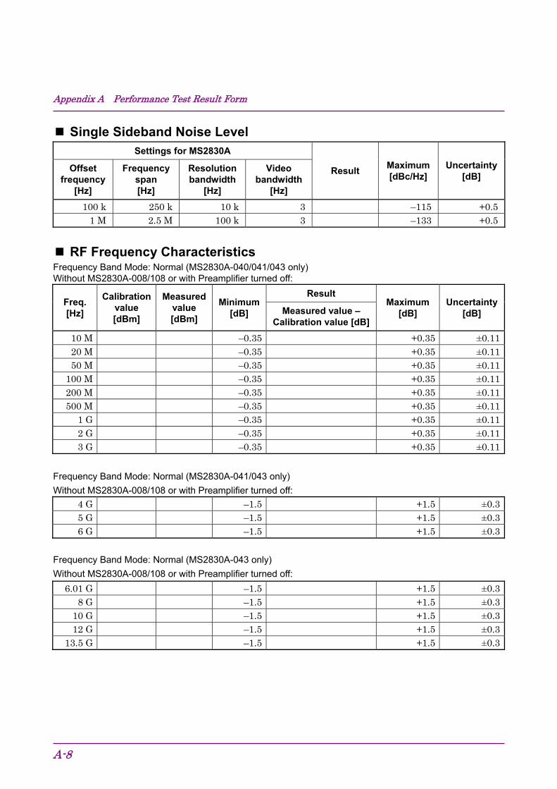
Appendix A Performance Test Result Form
A-8
Single Sideband Noise Level Settings for MS2830A
Result Maximum [dBc/Hz]
Uncertainty [dB]
Offset frequency
[Hz]
Frequency span [Hz]
Resolution bandwidth
[Hz]
Video bandwidth
[Hz]
100 k 250 k 10 k 3 –115 +0.51 M 2.5 M 100 k 3 –133 +0.5
RF Frequency Characteristics Frequency Band Mode: Normal (MS2830A-040/041/043 only) Without MS2830A-008/108 or with Preamplifier turned off:
Freq. [Hz]
Calibration value [dBm]
Measured value [dBm]
Minimum [dB]
Result Maximum
[dB] Uncertainty
[dB] Measured value – Calibration value [dB]
10 M –0.35 +0.35 ±0.1120 M –0.35 +0.35 ±0.1150 M –0.35 +0.35 ±0.11
100 M –0.35 +0.35 ±0.11200 M –0.35 +0.35 ±0.11500 M –0.35 +0.35 ±0.11
1 G –0.35 +0.35 ±0.112 G –0.35 +0.35 ±0.113 G –0.35 +0.35 ±0.11
Frequency Band Mode: Normal (MS2830A-041/043 only) Without MS2830A-008/108 or with Preamplifier turned off:
4 G –1.5 +1.5 ±0.35 G –1.5 +1.5 ±0.36 G –1.5 +1.5 ±0.3
Frequency Band Mode: Normal (MS2830A-043 only) Without MS2830A-008/108 or with Preamplifier turned off:
6.01 G –1.5 +1.5 ±0.38 G –1.5 +1.5 ±0.3
10 G –1.5 +1.5 ±0.312 G –1.5 +1.5 ±0.3
13.5 G –1.5 +1.5 ±0.3

A.1 Performance Test Result Form
A-9
Ap
pen
dix
Appen
dix A
Frequency Band Mode: Normal (MS2830A-040/041/043 only) With MS2830A-008/108 and Preamplifier turned on:
Freq. [Hz]
Calibration value [dBm]
Measured value [dBm]
Minimum [dB]
Result Maximum
[dB] Uncertainty
[dB] Measured value – Calibration value [dB]
50 M –0.65 +0.65 ±0.15100 M –0.65 +0.65 ±0.15200 M –0.65 +0.65 ±0.15500 M –0.65 +0.65 ±0.15
1 G –0.65 +0.65 ±0.152 G –0.65 +0.65 ±0.153 G –0.65 +0.65 ±0.15
Frequency Band Mode: Normal (MS2830A-041/043 only) With MS2830A-008/108 and Preamplifier turned on:
4 G –1.8 +1.8 ±0.155 G –1.8 +1.8 ±0.156 G –1.8 +1.8 ±0.15

Appendix A Performance Test Result Form
A-10
Frequency Band Mode: Normal (MS2830A-044/045 only) With MS2830A-008/108 and Preamplifier turned on:
Freq. [Hz]
Calibration value [dBm]
Measured value [dBm]
Minimum [dB]
Result
Maximum [dB]
Uncertainty [dB]
Measured value – Calibration value
[dB]
10 M –0.65 +0.65 ±0.1520 M –0.65 +0.65 ±0.1550 M –0.65 +0.65 ±0.15
100 M –0.65 +0.65 ±0.15200 M –0.65 +0.65 ±0.15500 M –0.65 +0.65 ±0.15
1 G –0.65 +0.65 ±0.152 G –0.65 +0.65 ±0.153 G –0.65 +0.65 ±0.154 G –1.8 +1.8 ±0.155 G –1.8 +1.8 ±0.156 G –1.8 +1.8 ±0.15
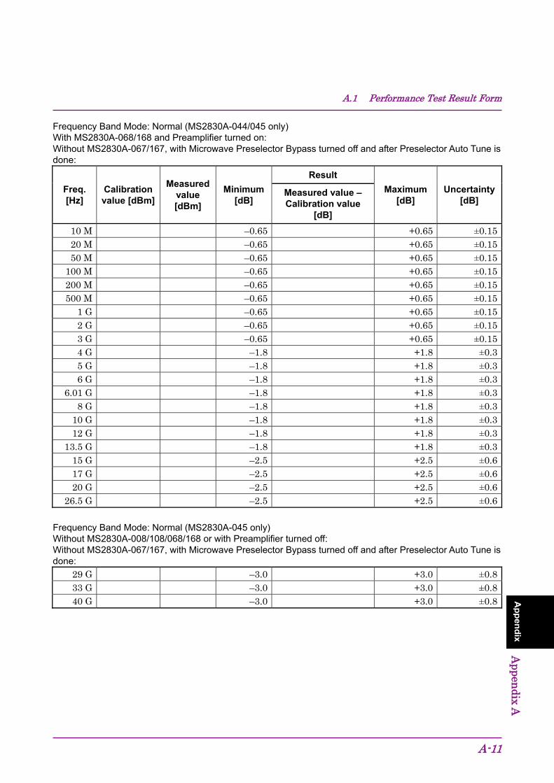
A.1 Performance Test Result Form
A-11
Ap
pen
dix
Appen
dix A
Frequency Band Mode: Normal (MS2830A-044/045 only) With MS2830A-068/168 and Preamplifier turned on: Without MS2830A-067/167, with Microwave Preselector Bypass turned off and after Preselector Auto Tune is done:
Freq. [Hz]
Calibration value [dBm]
Measured value [dBm]
Minimum [dB]
Result
Maximum [dB]
Uncertainty [dB]
Measured value – Calibration value
[dB]
10 M –0.65 +0.65 ±0.1520 M –0.65 +0.65 ±0.1550 M –0.65 +0.65 ±0.15
100 M –0.65 +0.65 ±0.15200 M –0.65 +0.65 ±0.15500 M –0.65 +0.65 ±0.15
1 G –0.65 +0.65 ±0.152 G –0.65 +0.65 ±0.153 G –0.65 +0.65 ±0.154 G –1.8 +1.8 ±0.35 G –1.8 +1.8 ±0.36 G –1.8 +1.8 ±0.3
6.01 G –1.8 +1.8 ±0.38 G –1.8 +1.8 ±0.3
10 G –1.8 +1.8 ±0.312 G –1.8 +1.8 ±0.3
13.5 G –1.8 +1.8 ±0.315 G –2.5 +2.5 ±0.617 G –2.5 +2.5 ±0.620 G –2.5 +2.5 ±0.6
26.5 G –2.5 +2.5 ±0.6
Frequency Band Mode: Normal (MS2830A-045 only) Without MS2830A-008/108/068/168 or with Preamplifier turned off: Without MS2830A-067/167, with Microwave Preselector Bypass turned off and after Preselector Auto Tune is done:
29 G –3.0 +3.0 ±0.833 G –3.0 +3.0 ±0.840 G –3.0 +3.0 ±0.8
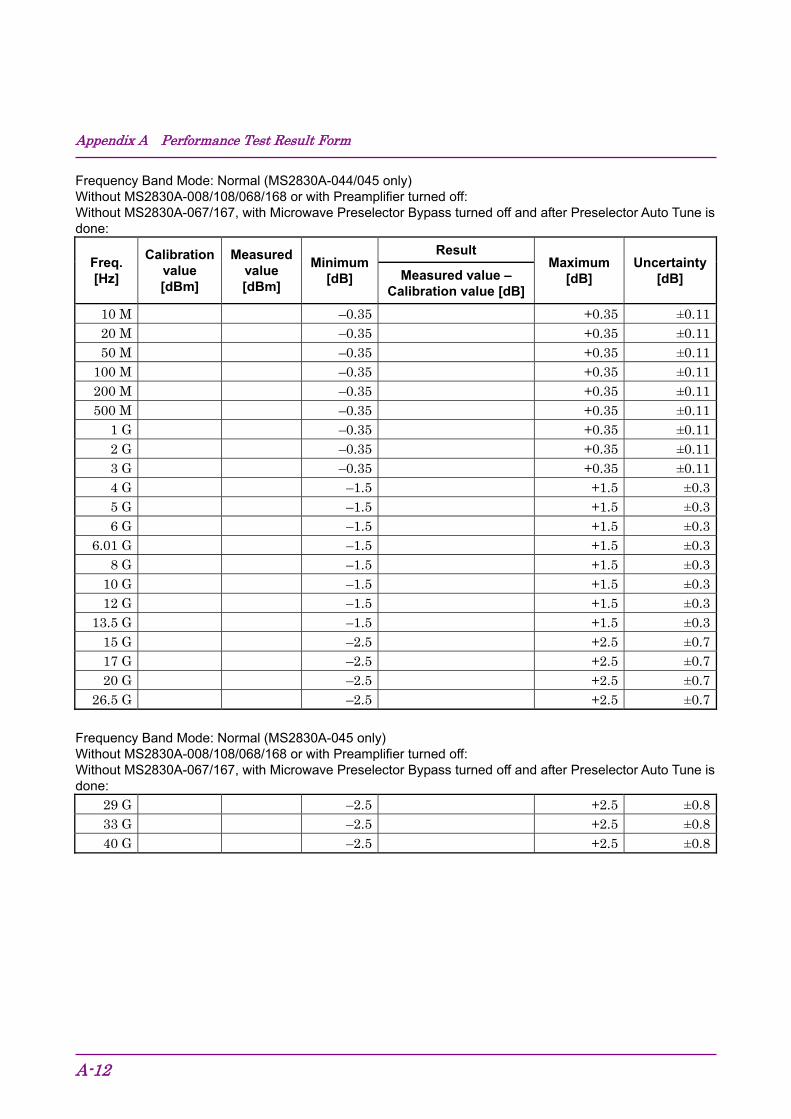
Appendix A Performance Test Result Form
A-12
Frequency Band Mode: Normal (MS2830A-044/045 only) Without MS2830A-008/108/068/168 or with Preamplifier turned off: Without MS2830A-067/167, with Microwave Preselector Bypass turned off and after Preselector Auto Tune is done:
Freq. [Hz]
Calibration value [dBm]
Measured value [dBm]
Minimum [dB]
Result Maximum
[dB] Uncertainty
[dB] Measured value – Calibration value [dB]
10 M –0.35 +0.35 ±0.1120 M –0.35 +0.35 ±0.1150 M –0.35 +0.35 ±0.11
100 M –0.35 +0.35 ±0.11200 M –0.35 +0.35 ±0.11500 M –0.35 +0.35 ±0.11
1 G –0.35 +0.35 ±0.112 G –0.35 +0.35 ±0.113 G –0.35 +0.35 ±0.114 G –1.5 +1.5 ±0.35 G –1.5 +1.5 ±0.36 G –1.5 +1.5 ±0.3
6.01 G –1.5 +1.5 ±0.38 G –1.5 +1.5 ±0.3
10 G –1.5 +1.5 ±0.312 G –1.5 +1.5 ±0.3
13.5 G –1.5 +1.5 ±0.315 G –2.5 +2.5 ±0.717 G –2.5 +2.5 ±0.720 G –2.5 +2.5 ±0.7
26.5 G –2.5 +2.5 ±0.7
Frequency Band Mode: Normal (MS2830A-045 only) Without MS2830A-008/108/068/168 or with Preamplifier turned off: Without MS2830A-067/167, with Microwave Preselector Bypass turned off and after Preselector Auto Tune is done:
29 G –2.5 +2.5 ±0.833 G –2.5 +2.5 ±0.840 G –2.5 +2.5 ±0.8

A.1 Performance Test Result Form
A-13
Ap
pen
dix
Appen
dix A
Display Average Noise Level Frequency Band Mode: Normal (MS2830A-040/041/043 only) Without MS2830A-062/066, and without MS2830A-008/108 or with Preamplifier turned off:
Center freq [Hz]
Display Average Noise Level [dBm/Hz]
Maximum [dBm/Hz]
100 k –1341 M –144
30 M –15399 M
999 M 1999 M
–1512399 M 2999 M –1493999 M
–1464999 M 5999 M 6001 M
–1428001 M 9999 M
11499 M –142
13499 M
Frequency Band Mode: Normal (MS2830A-040/041/043 only) Without MS2830A-062/066, and with MS2830A-008/108 and Preamplifier turned on:
Center freq [Hz]
Display average noise level [dBm/Hz]
Maximum [dBm/Hz]
1 M –15630 M
–16399 M 999 M
1999 M –1622399 M
–1602999 M 3999 M –1574999 M
–1576000 M
Note:
MS2830A-040: 100 kHz to 3600 MHz MS2830A-041: 100 kHz to 6000 MHz MS2830A-043: 100 kHz to 13500 MHz
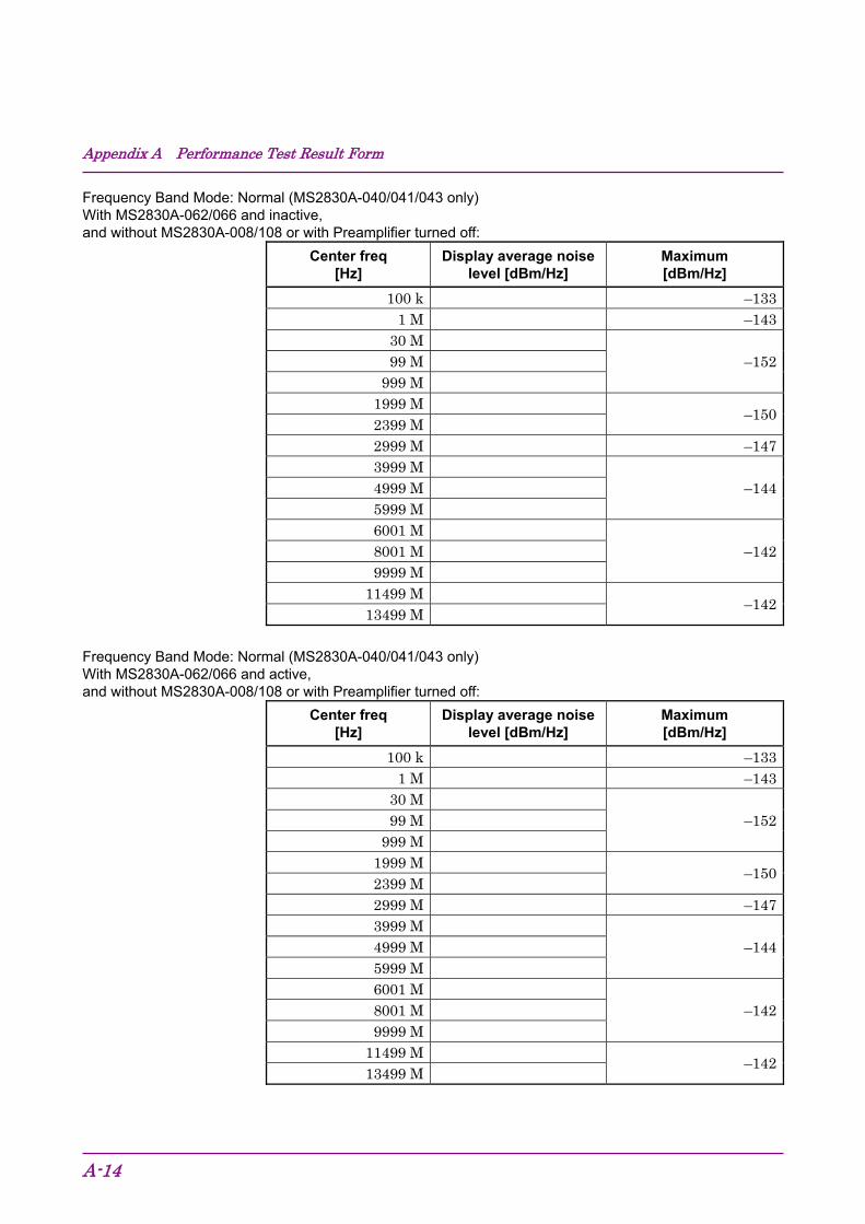
Appendix A Performance Test Result Form
A-14
Frequency Band Mode: Normal (MS2830A-040/041/043 only) With MS2830A-062/066 and inactive, and without MS2830A-008/108 or with Preamplifier turned off:
Center freq [Hz]
Display average noise level [dBm/Hz]
Maximum [dBm/Hz]
100 k –1331 M –143
30 M –15299 M
999 M 1999 M
–1502399 M 2999 M –1473999 M
–1444999 M 5999 M 6001 M
–1428001 M 9999 M
11499 M –142
13499 M
Frequency Band Mode: Normal (MS2830A-040/041/043 only) With MS2830A-062/066 and active, and without MS2830A-008/108 or with Preamplifier turned off:
Center freq [Hz]
Display average noise level [dBm/Hz]
Maximum [dBm/Hz]
100 k –1331 M –143
30 M –15299 M
999 M 1999 M
–1502399 M 2999 M –1473999 M
–1444999 M 5999 M 6001 M
–1428001 M 9999 M
11499 M –142
13499 M
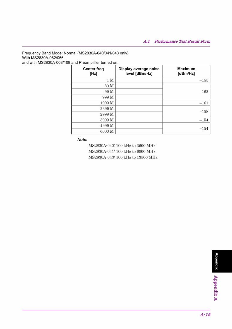
A.1 Performance Test Result Form
A-15
Ap
pen
dix
Appen
dix A
Frequency Band Mode: Normal (MS2830A-040/041/043 only) With MS2830A-062/066, and with MS2830A-008/108 and Preamplifier turned on:
Center freq [Hz]
Display average noise level [dBm/Hz]
Maximum [dBm/Hz]
1 M –15530 M
–16299 M 999 M
1999 M –1612399 M
–1582999 M 3999 M –1544999 M
–1546000 M
Note:
MS2830A-040: 100 kHz to 3600 MHz MS2830A-041: 100 kHz to 6000 MHz MS2830A-043: 100 kHz to 13500 MHz

Appendix A Performance Test Result Form
A-16
Frequency Band Mode: Normal (MS2830A-044/045 only) Without MS2830A-067/167/068/168:
Center freq [Hz]
Display average noise level [dBm/Hz]
Maximum [dBm/Hz]
100 k –1341 M –144
30 M –15399 M
999 M 1999 M
–1502399 M 2999 M –1473999 M –1444999 M
–1445999 M 6001 M
–1518001 M 9999 M
11499 M 13499 M 18399 M –14626499 M –14639999 M –14442999 M –140
Note: MS2830A-044: 100 kHz to 26500 MHz MS2830A-045: 100 kHz to 43000 MHz
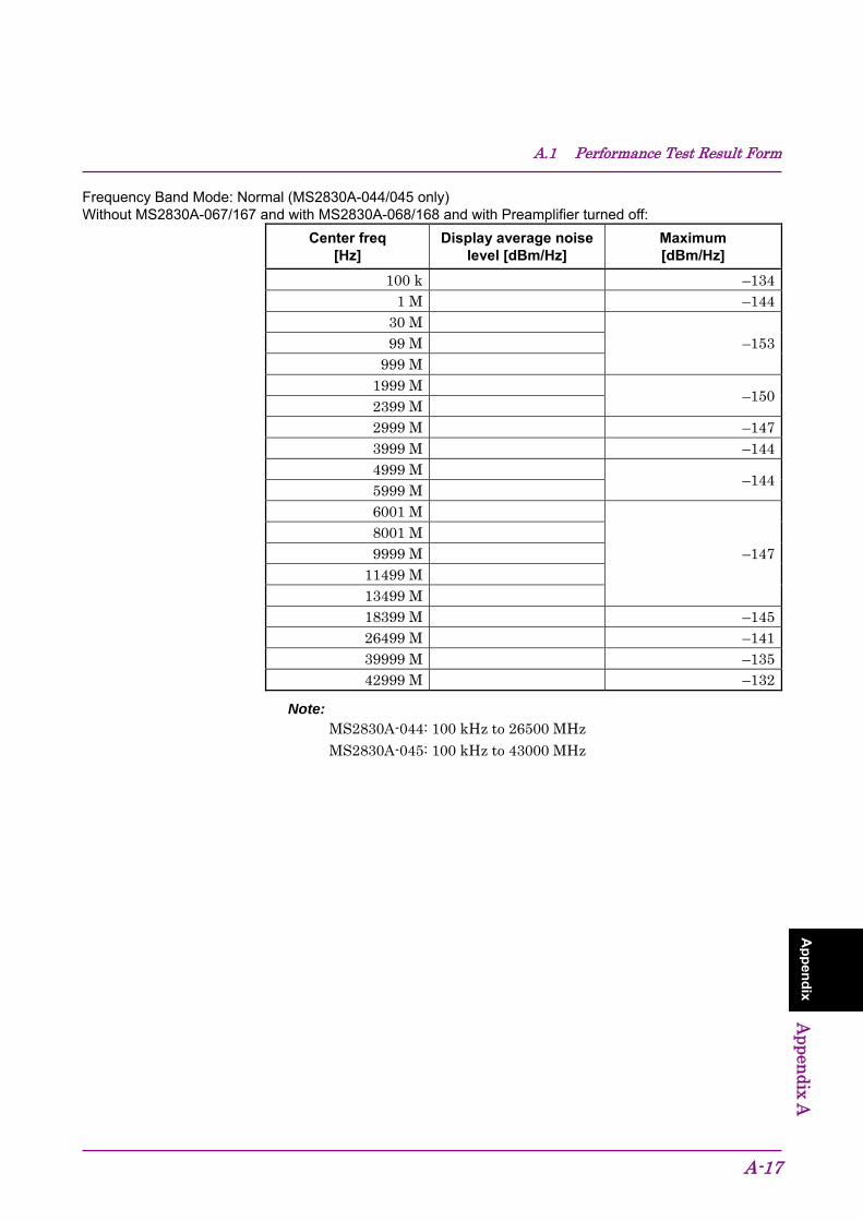
A.1 Performance Test Result Form
A-17
Ap
pen
dix
Appen
dix A
Frequency Band Mode: Normal (MS2830A-044/045 only) Without MS2830A-067/167 and with MS2830A-068/168 and with Preamplifier turned off:
Center freq [Hz]
Display average noise level [dBm/Hz]
Maximum [dBm/Hz]
100 k –1341 M –144
30 M –15399 M
999 M 1999 M
–1502399 M 2999 M –1473999 M –1444999 M
–1445999 M 6001 M
–1478001 M 9999 M
11499 M 13499 M 18399 M –14526499 M –14139999 M –13542999 M –132
Note: MS2830A-044: 100 kHz to 26500 MHz MS2830A-045: 100 kHz to 43000 MHz
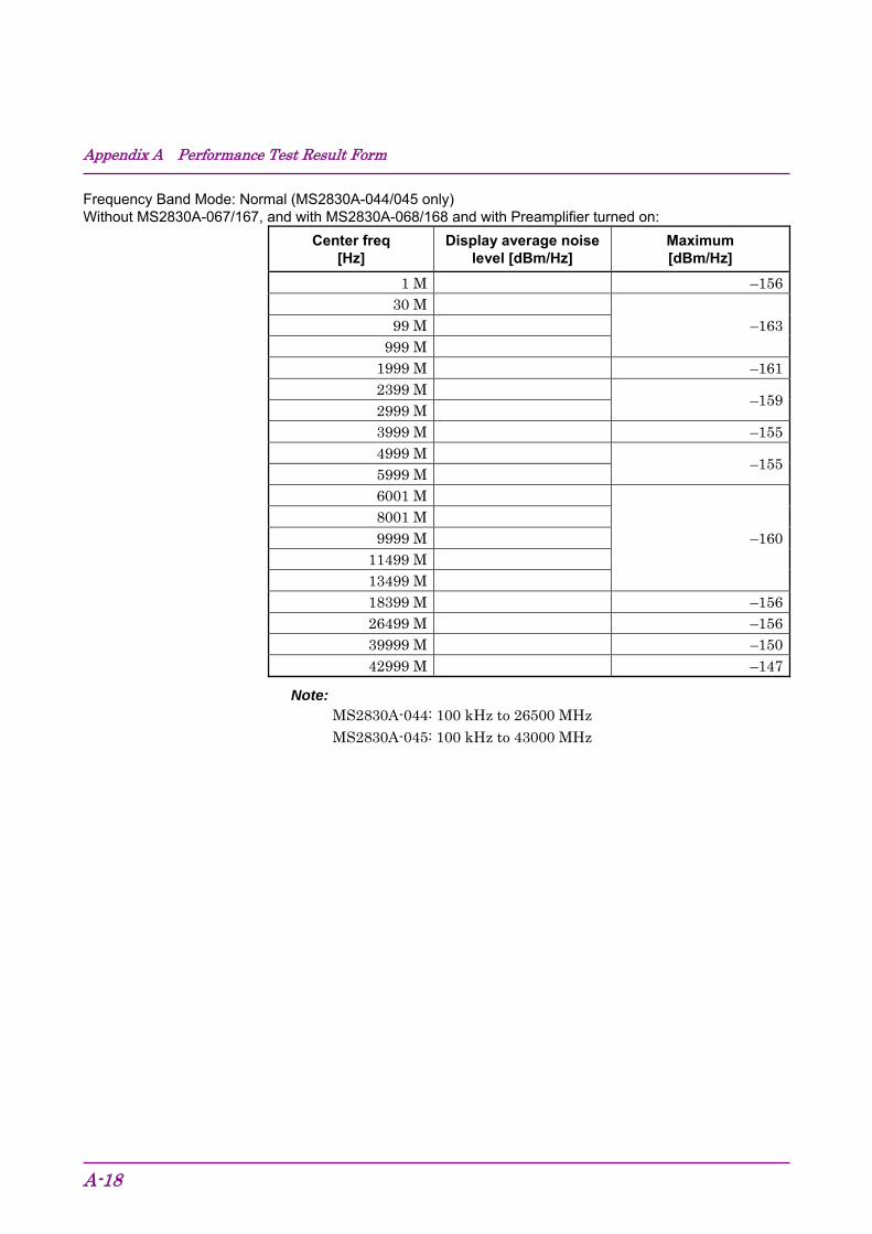
Appendix A Performance Test Result Form
A-18
Frequency Band Mode: Normal (MS2830A-044/045 only) Without MS2830A-067/167, and with MS2830A-068/168 and with Preamplifier turned on:
Center freq [Hz]
Display average noise level [dBm/Hz]
Maximum [dBm/Hz]
1 M –15630 M
–16399 M 999 M
1999 M –1612399 M
–1592999 M 3999 M –1554999 M
–1555999 M 6001 M
–1608001 M 9999 M
11499 M 13499 M 18399 M –15626499 M –15639999 M –15042999 M –147
Note: MS2830A-044: 100 kHz to 26500 MHz MS2830A-045: 100 kHz to 43000 MHz
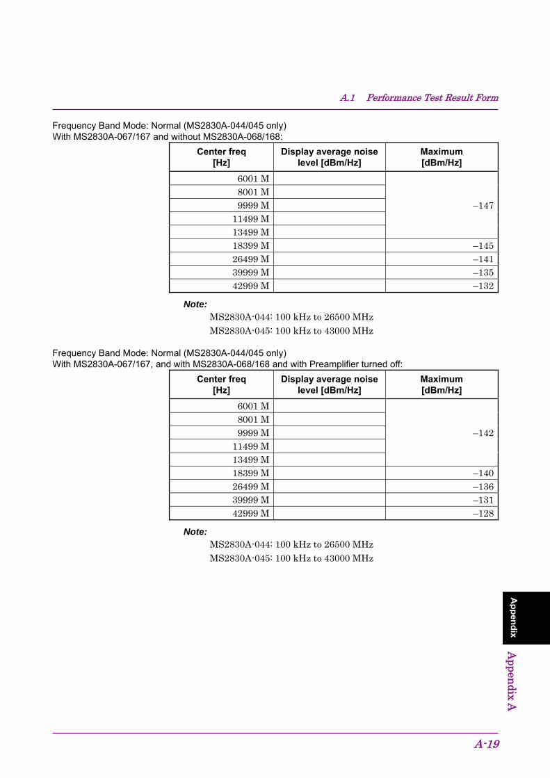
A.1 Performance Test Result Form
A-19
Ap
pen
dix
Appen
dix A
Frequency Band Mode: Normal (MS2830A-044/045 only) With MS2830A-067/167 and without MS2830A-068/168:
Center freq [Hz]
Display average noise level [dBm/Hz]
Maximum [dBm/Hz]
6001 M
–1478001 M 9999 M
11499 M 13499 M 18399 M –14526499 M –14139999 M –13542999 M –132
Note: MS2830A-044: 100 kHz to 26500 MHz MS2830A-045: 100 kHz to 43000 MHz
Frequency Band Mode: Normal (MS2830A-044/045 only) With MS2830A-067/167, and with MS2830A-068/168 and with Preamplifier turned off:
Center freq [Hz]
Display average noise level [dBm/Hz]
Maximum [dBm/Hz]
6001 M
–1428001 M 9999 M
11499 M 13499 M 18399 M –14026499 M –13639999 M –13142999 M –128
Note: MS2830A-044: 100 kHz to 26500 MHz MS2830A-045: 100 kHz to 43000 MHz
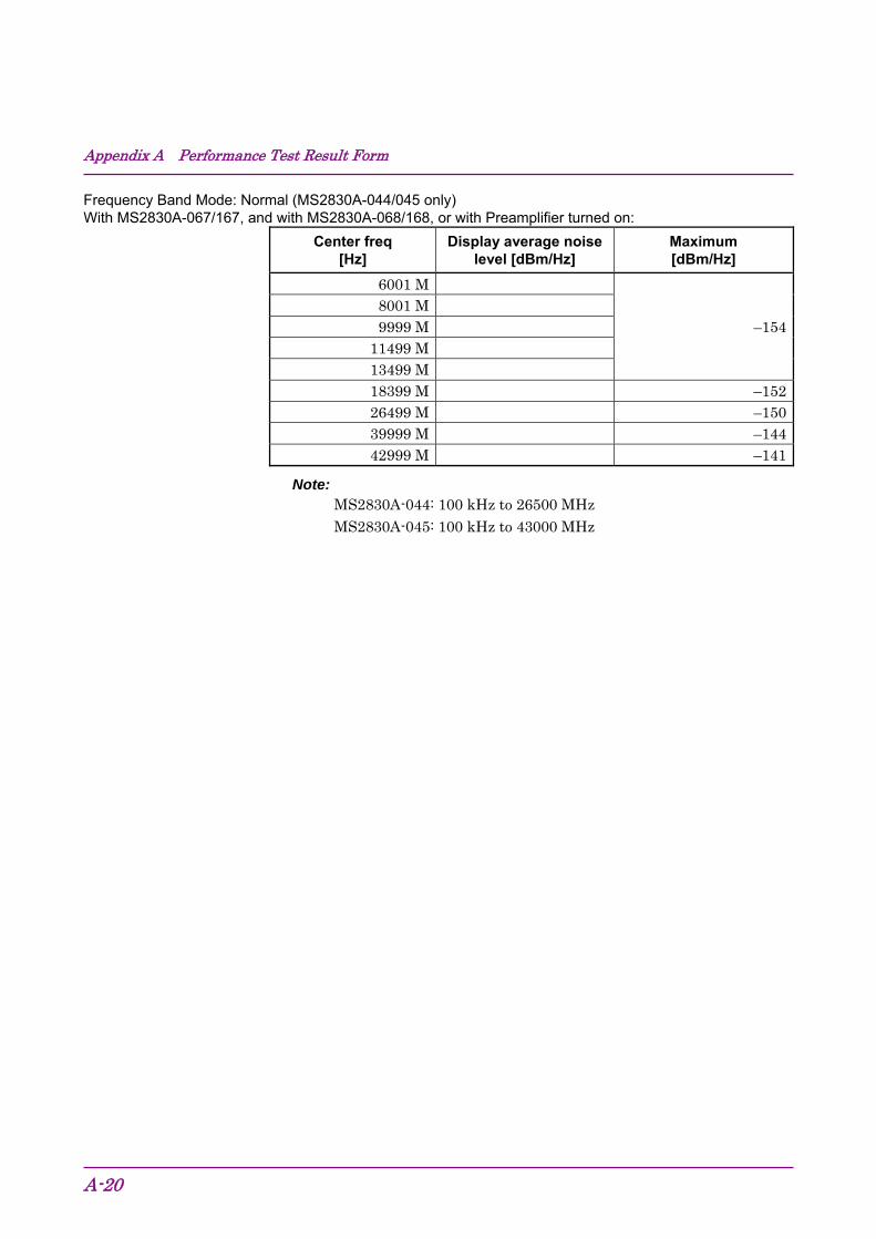
Appendix A Performance Test Result Form
A-20
Frequency Band Mode: Normal (MS2830A-044/045 only) With MS2830A-067/167, and with MS2830A-068/168, or with Preamplifier turned on:
Center freq [Hz]
Display average noise level [dBm/Hz]
Maximum [dBm/Hz]
6001 M
–1548001 M 9999 M
11499 M 13499 M 18399 M –15226499 M –15039999 M –14442999 M –141
Note: MS2830A-044: 100 kHz to 26500 MHz MS2830A-045: 100 kHz to 43000 MHz

A.1 Performance Test Result Form
A-21
Ap
pen
dix
Appen
dix A
Second Harmonic Wave Distortion
MS2830A-040/041/043 Without MS2830A-008/108 or with Preamplifier turned off:
Settings for MS2830A
Result [dBc]
Maximum [dBc] Uncer- tainty [dB]
Freq. [MHz]
Ref_Level [dBm]
Output level
[dBm]
Applicable LPF
51 –30 –20 SLP–50+ (Mixer Input level = –30 dBm)
–60 +1.5
401 –30 –20 VLF–400 (+)
(Mixer Input level = –30 dBm)
–65
+1.5
1799 –30 –20 VLF–2250 (+) (2-stage series)
+1.5
2999 0 0 VLF–3000 (+) (2-stage series)
(Mixer Input level = –10 dBm)
–70
+3.0
5999 0 0 VLF–6000 (+) (2-stage series)
+3.0
Appendix A Performance Test Result Form
A-22
MS2830A-040/041/043 With MS2830A-008/108 and Preamplifier turned on:
Settings for MS2830A
Result [dBc]
Maximum [dBc]
Uncer- tainty
[dB] Freq. [MHz]
Ref_Level [dBm]
Output level
[dBm]
Applicable LPF
51 –35 –35 SLP–50+ (Preamp input level = –45 dBm)
–50 +1.5
401 –35 –35 VLF–400 (+)
(Preamp input level = –45 dBm)
–55
+1.5
2999 –35 –35 VLF–3000 (+) (2-stage series)
+1.5
MS2830A-044/045 Without MS2830A-008/108/068/168 and without MS2830A-067/167:
Settings for MS2830A
Result [dBc]
Maximum [dBc] Uncer- tainty [dB]
Freq. [MHz]
Ref_Level [dBm]
Output level
[dBm]
Applicable LPF
51 –30 –20 SLP–50+ (Mixer Input level = –30 dBm)
–60 +1.5
401 –30 –20 VLF–400 (+)
(Mixer Input level = –30 dBm)
–65
+1.5
1799 –30 –20 VLF–2250 (+) (2-stage series)
+1.5
2999 0 0 VLF–3000 (+) (2-stage series)
(Mixer Input level = –10 dBm)
–70 +3.0
5999 0 0 VLF–6000 (+) (2-stage series)
(Mixer Input level = –10 dBm)
–90
+3.0
6749 0 0 VLF–6700 (+) (2-stage series)
+3.0

A.1 Performance Test Result Form
A-23
Ap
pen
dix
Appen
dix A
MS2830A-044/045 With MS2830A-068/168 or with Preamplifier turned off: Or, with MS2830A-067/167 and Microwave Preselector Bypass turned off:
Settings for MS2830A
Result [dBc]
Maximum [dBc] Uncer- tainty [dB]
Freq. [MHz]
Ref_Level [dBm]
Output level
[dBm]
Applicable LPF
51 –30 –20 SLP–50+ (Mixer Input level = –30 dBm)
–60 +1.5
401 –30 –20 VLF–400 (+)
(Mixer Input level = –30 dBm)
–65
+1.5
1799 –30 –20 VLF–2250 (+) (2-stage series)
+1.5
2999 0 0 VLF–3000 (+) (2-stage series)
(Mixer Input level = –10 dBm)
–70
+3.0
5999 0 0 VLF–6000 (+) (2-stage series)
+3.0
6749 0 0 VLF–6700 (+) (2-stage series)
+3.0
Appendix A Performance Test Result Form
A-24.
MS2830A-044/045 With MS2830A-008/108/068/168 or with Preamplifier turned on:
Settings for MS2830A
Result [dBc]
Maximum [dBc] Uncer- tainty [dB]
Freq. [MHz]
Ref_Level [dBm]
Output level
[dBm]
Applicable LPF
51 –30 –20 SLP–50+ (Mixer Input level = –45 dBm)
–50 +1.5
401 –30 –20 VLF–400 (+) (Mixer Input level = –45 dBm)
–55
+1.5
1799 –30 –20 VLF–2250 (+) (2-stage series)
+1.5
2999 –30 –20 VLF–3000 (+) (2-stage series)
(Mixer Input level = –45 dBm)
–45
+3.0
5999 –30 –20 VLF–6000 (+) (2-stage series)
+3.0
6749 –30 –20 VLF–6700 (+) (2-stage series)
+3.0
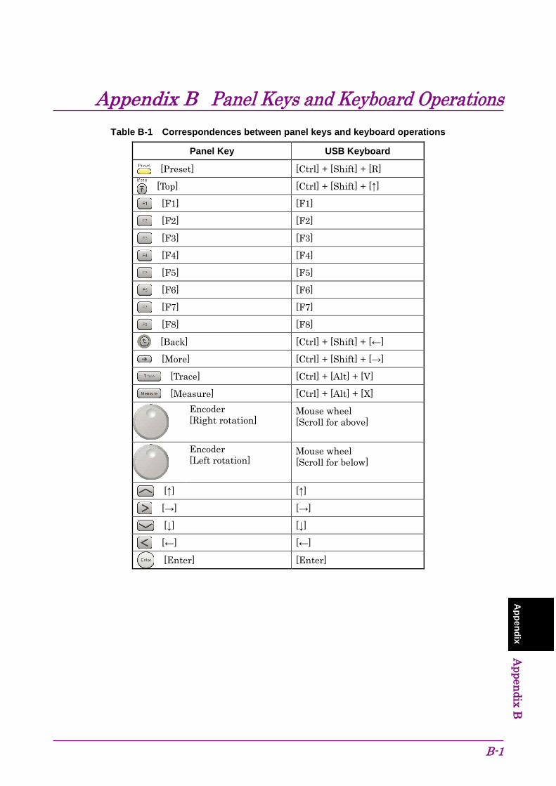
B-1
Appendix Appendix B
Appendix B Panel Keys and Keyboard Operations
Table B-1 Correspondences between panel keys and keyboard operations
Panel Key USB Keyboard
[Preset] [Ctrl] + [Shift] + [R]
[Top] [Ctrl] + [Shift] + [↑]
[F1] [F1]
[F2] [F2]
[F3] [F3]
[F4] [F4]
[F5] [F5]
[F6] [F6]
[F7] [F7]
[F8] [F8]
[Back] [Ctrl] + [Shift] + [←]
[More] [Ctrl] + [Shift] + [→]
[Trace] [Ctrl] + [Alt] + [V]
[Measure] [Ctrl] + [Alt] + [X]
Encoder [Right rotation]
Mouse wheel [Scroll for above]
Encoder [Left rotation]
Mouse wheel [Scroll for below]
[↑] [↑]
[→] [→]
[↓] [↓]
[←] [←]
[Enter] [Enter]

Appendix B Panel Keys and Keyboard Operations
B-2
Table B-1 Correspondences between panel keys and keyboard operations (Cont’d)
Panel Key USB Keyboard
[0] [0]
[1] [1]
[2] [2]
[3] [3]
[4] [4]
[5] [5]
[6] [6]
[7] [7]
[8] [8]
[9] [9]
[ . ] [ . ]
[+/-] [ - ]
[Shift] + [4] [A]
[Shift] + [5] [B]
[Shift] + [6] [C]
[Shift] + [7] [D]
[Shift] + [8] [E]
[Shift] + [9] [F]
[Cancel] [Esc]
[BS] [Back Space]
[Single] [Ctrl] + [Shift] + [F1]
[Continuous] [Ctrl] + [Shift] + [F2]
[Frequency] [Ctrl] + [Shift] + [0]
[Span] [Ctrl] + [Shift] + [1]
[Amplitude] [Ctrl] + [Shift] + [2]
[Marker] [Ctrl] + [Shift] + [3]
[BW] [Ctrl] + [Shift] + [4]
[Trigger/Gate] [Ctrl] + [Shift] + [5]
[Time/Sweep] [Ctrl] + [Shift] + [6]
[Peak Search] [Ctrl] + [Shift] + [7]
[Save] [Ctrl] + [S]
[Recall] [Ctrl] + [O]
[Copy] [Ctrl] + [Shift] + [8]

Appendix B Panel Keys and Keyboard Operations
B-3
Appendix Appendix B
Table B-1 Correspondences between panel keys and keyboard operations (Cont’d)
Panel Key USB Keyboard
[Cal] [Ctrl] + [Shift] + [9]
[SPA] Not available
[SA] Not available
[SG] Not available
[Appli] Not available
Note: The figure in [Ctrl] + [Shift] + “figure” cannot be entered by the numeric keypad.

Appendix B Panel Keys and Keyboard Operations
B-4.

C-1
Appendix Appendix C
Appendix C Virus Check Procedure (WES 2009) It is the customer’s responsibility to purchase, install, and operate anti-virus software on the MS2830A. Follow the manual of the anti-virus software you purchased.
This document explains the procedure of virus scanning without installing any anti-virus software on the MS2830A. Virus scanning can be performed by assigning the equipment drives to network drives on an external computer on which anti-virus software is installed.
Even if network drives cannot be scanned using your software, scanning might be possible by dragging and dropping a network drive onto the anti-virus software icon in Windows Explorer.
C.1 Connecting External PC to MS2830A ......................... C-3 C.2 Checking IP address of MS2830A .............................. C-3 C.3 Configuring shared settings ........................................ C-4 C.4 Changing the user account for the equipment ............ C-5 C.5 Shared Settings for MS2830A .................................... C-8 C.6 Mounting the equipment drives to
the external computer drives .................................... C-10 C.7 Scanning for virus .................................................... C-11 C.8 Unmounting the equipment drives from the external
computer drives ....................................................... C-11 C.9 Making the equipment drives unshared .................... C-11 C.10 Restoring the previous user account setting for the
equipment ................................................................ C-11 C.11 Enabling Simple File Sharing ................................... C-12

Appendix C Virus Check Procedure (WES 2009)
C-2
Notes:
• Be sure to follow the procedure described in this document. If this procedure is not followed, not only will it not be possible to check for viruses, but the equipment might become unusable.
If the equipment runs abnormally after removing viruses, execute system recovery to restore all drives to the factory default settings. For the procedure, refer to Section 5.3 “System Recovery Functions”.
After performing system recovery, the firmware might have to be upgraded to the latest version depending on when the equipment was released.
• Before using anti-virus software, be sure to check its usage and the license scope.
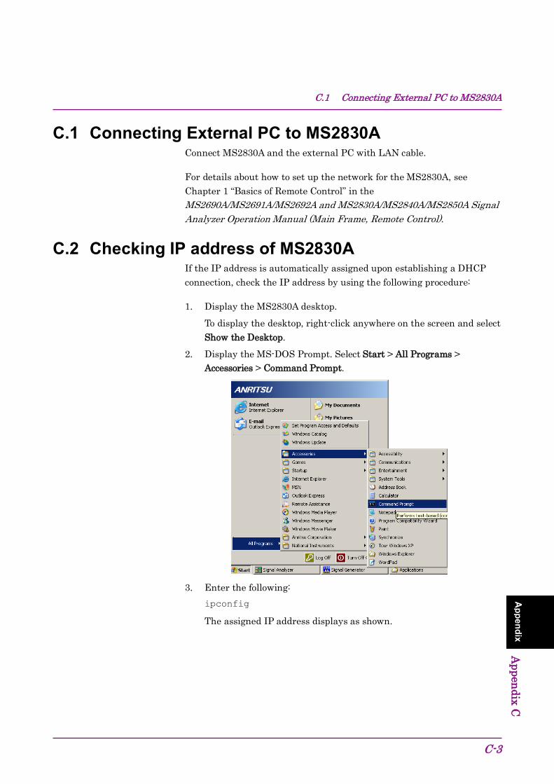
C.1 Connecting External PC to MS2830A
C-3
Appendix Appendix C
C.1 Connecting External PC to MS2830A Connect MS2830A and the external PC with LAN cable.
For details about how to set up the network for the MS2830A, see Chapter 1 “Basics of Remote Control” in the MS2690A/MS2691A/MS2692A and MS2830A/MS2840A/MS2850A Signal Analyzer Operation Manual (Main Frame, Remote Control).
C.2 Checking IP address of MS2830A If the IP address is automatically assigned upon establishing a DHCP connection, check the IP address by using the following procedure:
1. Display the MS2830A desktop. To display the desktop, right-click anywhere on the screen and select
Show the Desktop. 2. Display the MS-DOS Prompt. Select Start > All Programs >
Accessories > Command Prompt.
3. Enter the following: ipconfig
The assigned IP address displays as shown.

Appendix C Virus Check Procedure (WES 2009)
C-4
C.3 Configuring shared settings Simple File Sharing is enabled for the equipment by default. If authentication is performed by way of a network while Simple File Sharing is enabled, the accessing user is regarded as having a Guest account and cannot access important folders and files such as the Windows folder. To avoid this, use the following procedure to temporarily disable Simple File Sharing.
1. On MS2830A, click the Start button and then click My Computer. 2. In the Tool menu, click Folder Options, and click the View tab. 3. From the Advanced Settings list, make sure that the Use simple file
sharing (Recommended) is NOT selected.
4. Click OK.

C.4 Changing the user account for the equipment
C-5
Appendix Appendix C
C.4 Changing the user account for the equipment This section describes how to change the user account used when the equipment drives are mounted to network drives.
1. From the Start menu, select Control Panel. 2. Select Administrative Tools from the Control Panel.
3. Select Computer Management.
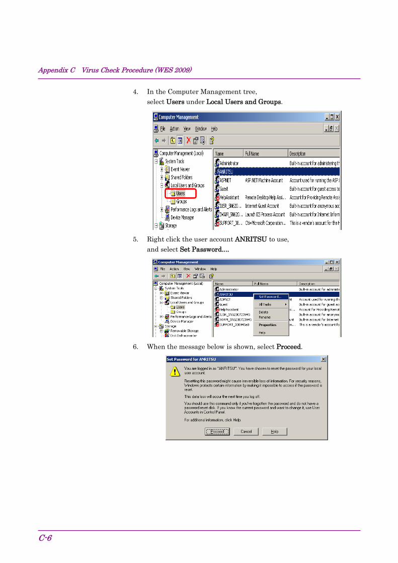
Appendix C Virus Check Procedure (WES 2009)
C-6
4. In the Computer Management tree, select Users under Local Users and Groups.
5. Right click the user account ANRITSU to use,
and select Set Password....
6. When the message below is shown, select Proceed.
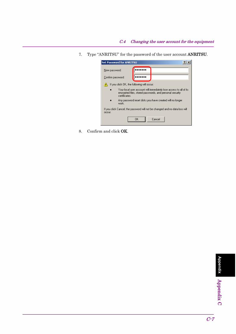
C.4 Changing the user account for the equipment
C-7
Appendix Appendix C
7. Type “ANRITSU” for the password of the user account ANRITSU.
8. Confirm and click OK.

Appendix C Virus Check Procedure (WES 2009)
C-8
C.5 Shared Settings for MS2830A 1. From the Start menu, select My Computer. 2. Right-click the C drive. 3. Select Sharing and Security. 4. Select the Sharing tab.
5. To disable currently enabled folder sharing setting, select Do not share this folder.
6. Click Apply.
(5)
(6)

C.5 Shared Settings for MS2830A
C-9
Appendix Appendix C
7. Sharing dialog box appears. Click Yes.
8. Select Share this folder. 9. Click Permissions.
10. Select Allow for Full control.
11. Click OK to close the two dialog boxes respectively. 12. Repeat steps 3 to 11 to the D drive.
(10)
(11)
(8)
(9)
(7)

Appendix C Virus Check Procedure (WES 2009)
C-10
C.6 Mounting the equipment drives to the external computer drives
1. On the computer connected by way of the network (which is used to run the anti-virus software), mount (assign) all the shared drives of the MS2830A as network drives.
2. On the PC, right click My Network Places, and select Map Network Drive. 3. Enter “The IP address of MS2830A + drive name” for the folder name.
Example When the IP address of the MS2830A is 192.168.0.1:
To mount the C drive, specify Y for Drive and \\192.168.0.1\c for Folder. To mount the D drive, specify Z for Drive and \\192.168.0.1\d for Folder.
4. Click Connect using a different user name. 5. Enter “ANRITSU” for the User name, and also “ANRITSU” for the
Password (as specified in C.4, Step 7).
6. Click OK > Finish to complete. 7. Repeat steps 2 to 6 to the D drive.
(3)
(4)
(5)
(6)
C.7 Scanning for virus
C-11
Appendix Appendix C
C.7 Scanning for virus Scan the network drives mounted on the external computer for viruses.
Even if network drives cannot be scanned using your software, scanning might be possible by dragging and dropping a network drive onto the anti-virus software icon in Windows Explorer.
C.8 Unmounting the equipment drives from the external computer drives
Right click My Network Places on the external PC, and select Disconnect Network Drive.
Unmount the two mapped drives.
C.9 Making the equipment drives unshared 1. From the Start menu, select My Computer. 2. Right-click the C drive. 3. Select Sharing and Security. 4. Select the Sharing tab. 5. Select Do not share this folder. 6. Repeat steps 2 to 5 to the D drive.
C.10 Restoring the previous user account setting for the equipment
The user account password has been changed in Section C.4 “Changing the user account for the equipment” for mounting the equipment drives to network drives of the external computer. Restore the password before change in the same way as it was changed. Note that no password is specified by default.

Appendix C Virus Check Procedure (WES 2009)
C-12.
C.11 Enabling Simple File Sharing Simple File Sharing has been disabled in Section C.3 “Configuring shared settings” for sharing drives. To restore the original settings, enable Simple File Sharing by using the following procedure:
1. On MS2830A, click the Start button and then click My Computer. 2. In the Tool menu, click Folder Options, and click the View tab. 3. From the Advanced Settings list, make sure that the Use simple file
sharing (Recommended) is selected.
4. Click OK.

D-1
Appendix Appendix D
Appendix D Virus Check Procedure (WES 7) It is the customer’s responsibility to purchase, install, and operate anti-virus software on the MS2830A. Follow the manual of the anti-virus software you purchased.
This document explains the procedure of virus scanning without installing any anti-virus software on the MS2830A. Virus scanning can be performed by assigning the equipment drives to network drives on an external computer on which anti-virus software is installed.
Even if network drives cannot be scanned using your software, scanning might be possible by dragging and dropping a network drive onto the anti-virus software icon in Windows Explorer.
D.1 Connecting External PC to MS2830A ......................... D-3 D.2 Checking IP address of MS2830A .............................. D-3 D.3 Configuring shared settings ........................................ D-4 D.4 Changing the user account for the equipment ............ D-5 D.5 Shared Settings for MS2830A .................................... D-8 D.6 Mounting the equipment drives to the external computer
drives ....................................................................... D-10 D.7 Scanning for virus .................................................... D-12 D.8 Unmounting the equipment drives from the external
computer drives ....................................................... D-12 D.9 Making the equipment drives unshared .................... D-12 D.10 Restoring the previous user account setting for the
equipment ................................................................ D-12 D.11 Enabling Simple File Sharing ................................... D-13
Appendix D Virus Check Procedure (WES 7)
D-2
Notes: • Be sure to follow the procedure described in this document. If
this procedure is not followed, not only will it not be possible to check for viruses, but the equipment might become unusable.
If the equipment runs abnormally after removing viruses, execute system recovery to restore all drives to the factory default settings. For the procedure, refer to Section 5.3 “System Recovery Functions”.
After performing system recovery, the firmware might have to be upgraded to the latest version depending on when the equipment was released.
• Before using anti-virus software, be sure to check its usage and the license scope.

D.1 Connecting External PC to MS2830A
D-3
Appendix Appendix D
D.1 Connecting External PC to MS2830A Connect MS2830A and the external PC with LAN cable.
For details about how to set up the network for the MS2830A, see Chapter 1 “Basics of Remote Control” in the MS2690A/MS2691A/MS2692A and MS2830A/MS2840A/MS2850A Signal Analyzer Operation Manual (Main Frame, Remote Control).
D.2 Checking IP address of MS2830A If the IP address is automatically assigned upon establishing a DHCP connection, check the IP address by using the following procedure:
1. Display the MS2830A desktop. To display the desktop, right-click anywhere on the screen and select
Show the Desktop. 2. Display the MS-DOS Prompt. Move a mouse downward on the
MS2830A screen to display the task bar. Select Start > All Programs > Accessories > Command Prompt.
3. Enter the following: ipconfig
The assigned IP address displays as shown.
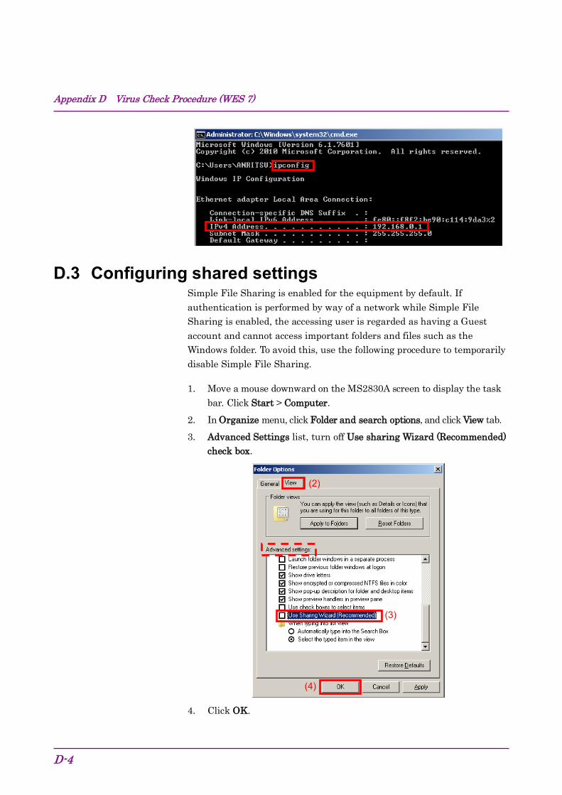
Appendix D Virus Check Procedure (WES 7)
D-4
D.3 Configuring shared settings Simple File Sharing is enabled for the equipment by default. If authentication is performed by way of a network while Simple File Sharing is enabled, the accessing user is regarded as having a Guest account and cannot access important folders and files such as the Windows folder. To avoid this, use the following procedure to temporarily disable Simple File Sharing.
1. Move a mouse downward on the MS2830A screen to display the task bar. Click Start > Computer.
2. In Organize menu, click Folder and search options, and click View tab. 3. Advanced Settings list, turn off Use sharing Wizard (Recommended)
check box.
4. Click OK.
(3)
(4)
(2)

D.4 Changing the user account for the equipment
D-5
Appendix Appendix D
D.4 Changing the user account for the equipment This section describes how to change the user account used when the equipment drives are mounted to network drives.
1. From the Start menu, click Control Panel. 2. Click Administrative Tools from the Control Panel.
3. Click Computer Management.
(3)
(2) (2)

Appendix D Virus Check Procedure (WES 7)
D-6
4. In Computer Management tree, click Users under Local Users and Groups.
5. Right click the user account ANRITSU to use,
and click Set Password…
6. When the message below is shown, click Proceed.
(6)
(5)
(4)

D.4 Changing the user account for the equipment
D-7
Appendix Appendix D
7. Type “ANRITSU” for the password of the user account ANRITSU.
8. Confirm and click OK.
(7)
(8)
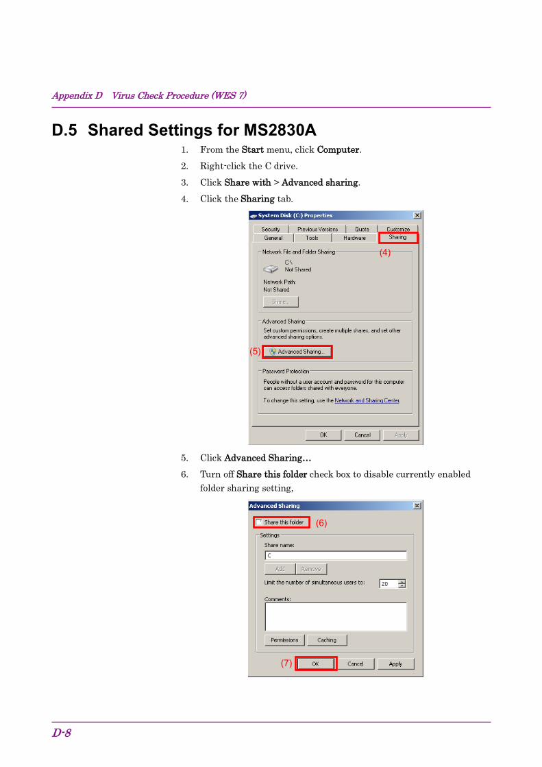
Appendix D Virus Check Procedure (WES 7)
D-8
D.5 Shared Settings for MS2830A 1. From the Start menu, click Computer. 2. Right-click the C drive. 3. Click Share with > Advanced sharing. 4. Click the Sharing tab.
5. Click Advanced Sharing… 6. Turn off Share this folder check box to disable currently enabled
folder sharing setting,
(6)
(7)
(4)
(5)

D.5 Shared Settings for MS2830A
D-9
Appendix Appendix D
7. Click OK 8. Sharing dialog box appears. Click Yes.
9. Turn on Share this folder check box. 10. Click Permissions.
11. Turn on Allow check box of Full Control.
12. Click OK to close the two dialog boxes respectively. 13. Repeat steps 2 to 12 to the D drive.
(11)
(12)
(10)
(9)
(8)

Appendix D Virus Check Procedure (WES 7)
D-10
D.6 Mounting the equipment drives to the external computer drives
1. On the computer connected by way of the network (which is used to run the anti-virus software), mount (assign) all the shared drives of the MS2830A as network drives.
2. On the PC, click Start > Computer. Right click Network on the Navigation window and click Map network drive…
3. Enter “The IP address of MS2830A + drive name” for the folder
name. Example When the IP address of the MS2830A is 192.168.0.1:
To mount the C drive, specify Y for Drive and \\192.168.0.1\c for Folder.
To mount the D drive, specify Z for Drive and \\192.168.0.1\d for Folder.
(2) (2)
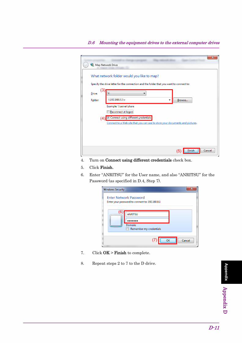
D.6 Mounting the equipment drives to the external computer drives
D-11
Appendix Appendix D
4. Turn on Connect using different credentials check box. 5. Click Finish. 6. Enter “ANRITSU” for the User name, and also “ANRITSU” for the
Password (as specified in D.4, Step 7).
7. Click OK > Finish to complete.
8. Repeat steps 2 to 7 to the D drive.
(6)
(7)
(3)
(4)
(5)

Appendix D Virus Check Procedure (WES 7)
D-12
D.7 Scanning for virus Scan the network drives mounted on the external computer for viruses.
D.8 Unmounting the equipment drives from the external computer drives
Right click My Network Places on the external PC, and select Disconnect Network Drive.
Unmount the two mapped drives.
D.9 Making the equipment drives unshared 1. From Start menu, click Computer. 2. Right-click the C drive. 3. Click Share with > Advanced sharing. 4. Click Sharing tab. 5. Click Advanced Sharing 6. Turn off Share this folder check box. 7. Click OK. 8. Sharing dialog box appears. Click Yes. 9. Repeat steps 2 to 8 to the D drive.
D.10 Restoring the previous user account setting for the equipment
The user account password has been changed in Section D.4 “Changing the user account for the equipment” for mounting the equipment drives to network drives of the external computer. Restore the password before change in the same way as it was changed. Note that no password is specified by default.

D.11 Enabling Simple File Sharing
D-13
Appendix Appendix D
D.11 Enabling Simple File Sharing Simple File Sharing has been disabled in Section D.3 “Configuring shared settings” for sharing drives. To restore the original settings, enable Simple File Sharing by using the following procedure:
1. On MS2830A, click Start > Computer. 2. In Organize menu, click Folder and search options, and click View tab. 3. From the Advanced Settings list, Turn on Use Sharing Wizard
(Recommended) check box.
4. Click OK.
(3)
(4)
(2)

Appendix D Virus Check Procedure (WES 7)
D-14.

E-1
Appendix Appendix E
Appendix E Virus Check Procedure (Windows 10) It is the customer’s responsibility to purchase, install, and operate anti-virus software on the MS2830A. Follow the manual of the anti-virus software you purchased.
This document explains the procedure of virus scanning without installing any anti-virus software on the MS2830A. Virus scanning can be performed by assigning the equipment drives to network drives on an external computer on which anti-virus software is installed.
Even if network drives cannot be scanned using your software, scanning might be possible by dragging and dropping a network drive onto the anti-virus software icon in Windows Explorer.
E.1 Connecting External PC to MS2830A ......................... E-3 E.2 Checking IP address of MS2830A .............................. E-3 E.3 Configuring shared settings ........................................ E-5 E.4 Changing the user account for the equipment ............ E-7 E.5 Shared Settings for MS2830A .................................. E-11 E.6 Mounting the equipment drives to the external
computer drives ....................................................... E-14 E.7 Scanning for virus .................................................... E-16 E.8 Unmounting the equipment drives from the external
computer drives ....................................................... E-16 E.9 Making the equipment drives unshared .................... E-16 E.10 Restoring the previous user account setting for the
equipment ................................................................ E-16 E.11 Enabling Simple File Sharing ................................... E-17

Appendix E Virus Check Procedure (Windows 10)
E-2
Notes: • Be sure to follow the procedure described in this document. If
this procedure is not followed, not only will it not be possible to check for viruses, but the equipment might become unusable.
If the equipment runs abnormally after removing viruses, execute system recovery to restore all drives to the factory default settings. For the procedure, refer to Section 5.3 “System Recovery Functions”.
After performing system recovery, the firmware might have to be upgraded to the latest version depending on when the equipment was released.
• Before using anti-virus software, be sure to check its usage and the license scope.
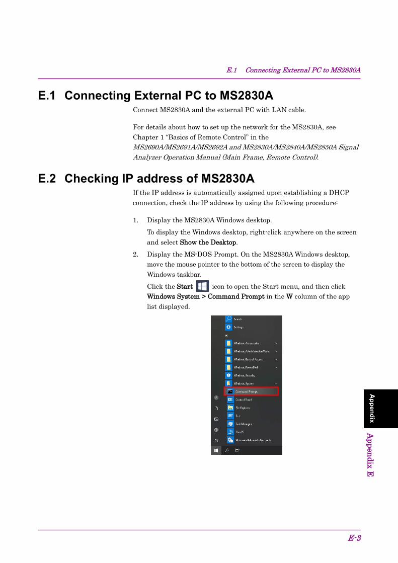
E.1 Connecting External PC to MS2830A
E-3
Appendix Appendix E
E.1 Connecting External PC to MS2830A Connect MS2830A and the external PC with LAN cable.
For details about how to set up the network for the MS2830A, see Chapter 1 “Basics of Remote Control” in the MS2690A/MS2691A/MS2692A and MS2830A/MS2840A/MS2850A Signal Analyzer Operation Manual (Main Frame, Remote Control).
E.2 Checking IP address of MS2830A If the IP address is automatically assigned upon establishing a DHCP connection, check the IP address by using the following procedure:
1. Display the MS2830A Windows desktop. To display the Windows desktop, right-click anywhere on the screen
and select Show the Desktop. 2. Display the MS-DOS Prompt. On the MS2830A Windows desktop,
move the mouse pointer to the bottom of the screen to display the Windows taskbar. Click the Start icon to open the Start menu, and then click Windows System > Command Prompt in the W column of the app list displayed.

Appendix E Virus Check Procedure (Windows 10)
E-4
3. Enter the following: ipconfig
The assigned IP address displays as shown.

E.3 Configuring shared settings
E-5
Appendix Appendix E
E.3 Configuring shared settings Simple File Sharing is enabled for the equipment by default. If authentication is performed by way of a network while Simple File Sharing is enabled, the accessing user is regarded as having a Guest account and cannot access important folders and files such as the Windows folder. To avoid this, use the following procedure to temporarily disable Simple File Sharing.
1. On the MS2830A Windows desktop, move the mouse pointer to the bottom of the screen to display the Windows taskbar. Right click the Start icon, and then click File Explorer.
2. In File Explorer window, click View tab and then click Options.
(2) (2)
(1)

Appendix E Virus Check Procedure (Windows 10)
E-6
3. In Folder Options dialog box, click View tab. Advanced Settings list, turn off Use Sharing Wizard (Recommended) check box.
4. Click OK.
(3)
(3)
(4)
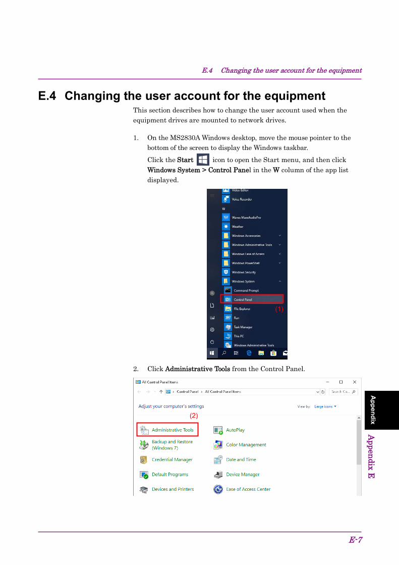
E.4 Changing the user account for the equipment
E-7
Appendix Appendix E
E.4 Changing the user account for the equipment This section describes how to change the user account used when the equipment drives are mounted to network drives.
1. On the MS2830A Windows desktop, move the mouse pointer to the bottom of the screen to display the Windows taskbar. Click the Start icon to open the Start menu, and then click Windows System > Control Panel in the W column of the app list displayed.
2. Click Administrative Tools from the Control Panel.
(1)
(2)

Appendix E Virus Check Procedure (Windows 10)
E-8
3. Click Computer Management in the Administrative Tools window.
4. In Computer Management tree, click Users under Local Users and Groups.
(3)
(4)

E.4 Changing the user account for the equipment
E-9
Appendix Appendix E
5. Right click the user account ANRITSU to use, and click Set Password…
6. When the message below is shown, click Proceed.
(5)
(6)
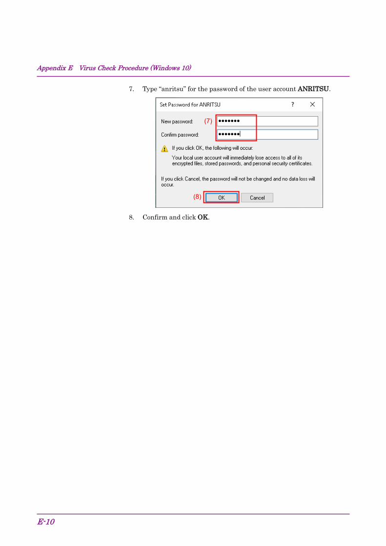
Appendix E Virus Check Procedure (Windows 10)
E-10
7. Type “anritsu” for the password of the user account ANRITSU.
8. Confirm and click OK.
(8)
(7)
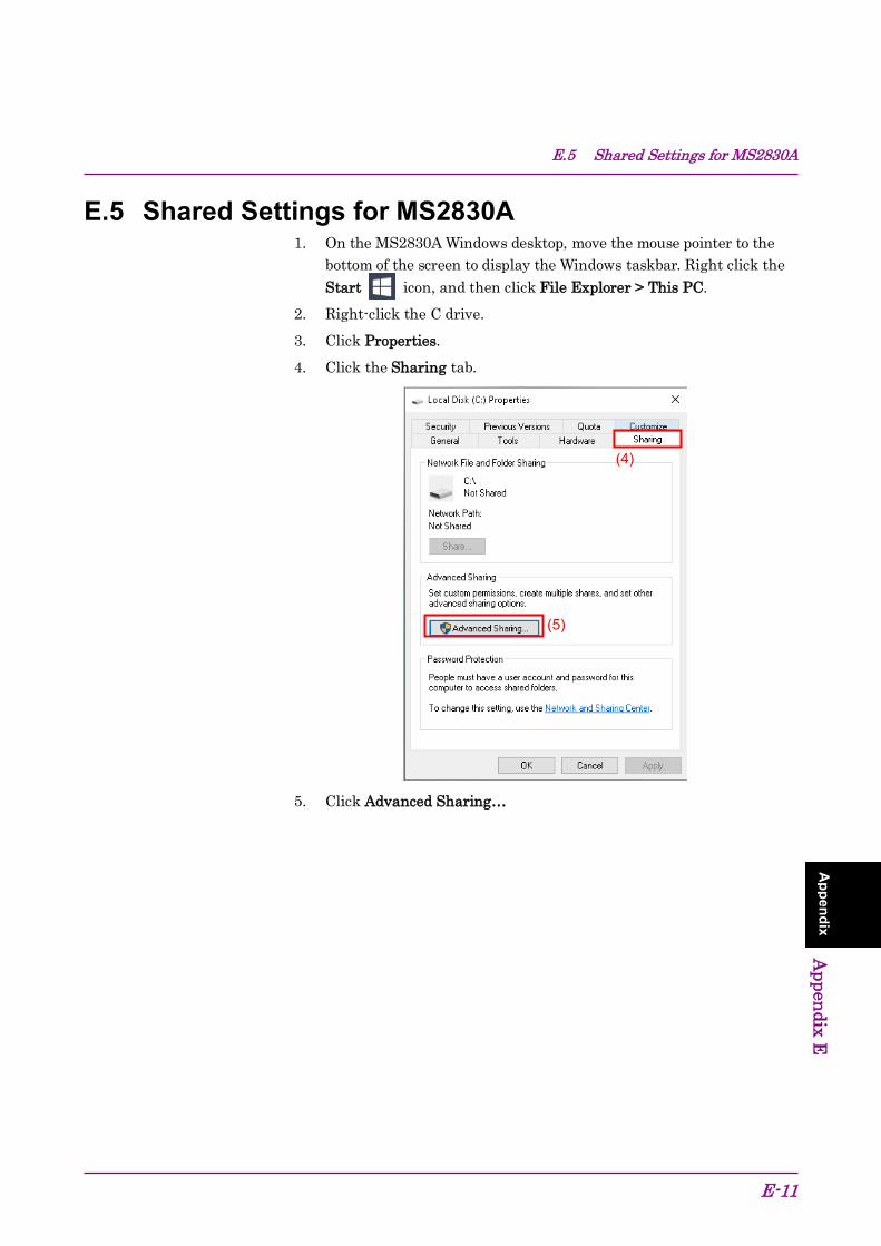
E.5 Shared Settings for MS2830A
E-11
Appendix Appendix E
E.5 Shared Settings for MS2830A 1. On the MS2830A Windows desktop, move the mouse pointer to the
bottom of the screen to display the Windows taskbar. Right click the Start icon, and then click File Explorer > This PC.
2. Right-click the C drive. 3. Click Properties. 4. Click the Sharing tab.
5. Click Advanced Sharing…
(4)
(5)

Appendix E Virus Check Procedure (Windows 10)
E-12
6. Turn off Share this folder check box to disable currently enabled folder sharing setting.
7. Click OK. 8. Sharing dialog box appears. Click Yes.
9. Turn on Share this folder check box. 10. Click Permissions.
(6)
(7)
(8)
(10)
(9)

E.5 Shared Settings for MS2830A
E-13
Appendix Appendix E
11. Turn on Allow check box of Full Control.
12. Click OK to close the two dialog boxes respectively. 13. Repeat steps 3 to 12 to the D drive.
(11)
(12)

Appendix E Virus Check Procedure (Windows 10)
E-14
E.6 Mounting the equipment drives to the external computer drives
On the computer connected by way of the network (which is used to run the anti-virus software), mount (assign) all the shared drives of the MS2830A as network drives. 1. Right click Start icon of the Windows taskbar on the external
PC and then click File Explorer. 2. Right click Network on the Navigation window and click Map
network drive…
3. Enter “The IP address of MS2830A + drive name” for the folder
name. Example When the IP address of the MS2830A is 192.168.20.3:
To mount the C drive, specify Y for Drive and \\192.168.20.3\c for Folder.
To mount the D drive, specify Z for Drive and \\192.168.20.3\d for Folder.
(2)
Document
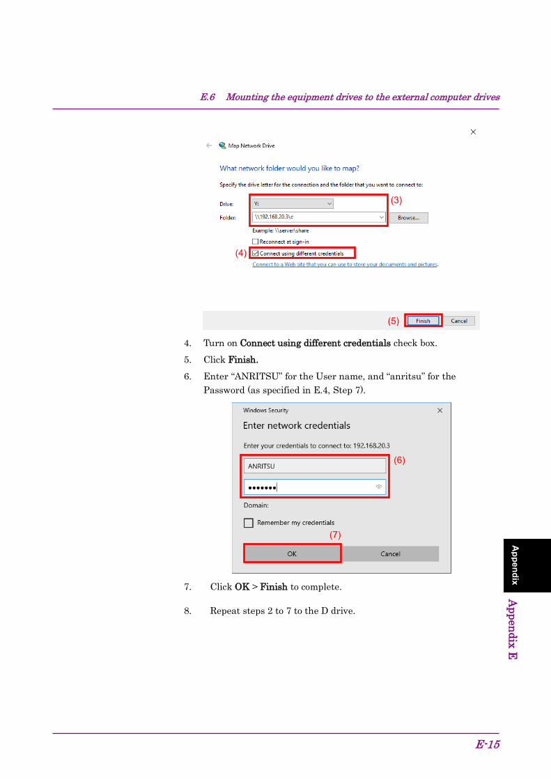
E.6 Mounting the equipment drives to the external computer drives
E-15
Appendix Appendix E
4. Turn on Connect using different credentials check box. 5. Click Finish. 6. Enter “ANRITSU” for the User name, and “anritsu” for the
Password (as specified in E.4, Step 7).
7. Click OK > Finish to complete.
8. Repeat steps 2 to 7 to the D drive.
(6)
(7)
(3)
(4)
(5)
Appendix E Virus Check Procedure (Windows 10)
E-16
E.7 Scanning for virus Scan the network drives mounted on the external computer for viruses.
E.8 Unmounting the equipment drives from the external computer drives
1. Right click Start icon of the Windows taskbar on the external PC and then click File Explorer.
2. Right click Network on the Navigation window and click Disconnect network drive.
3. Unmount the two mapped drives.
E.9 Making the equipment drives unshared 1. On the MS2830A Windows desktop, move the mouse pointer to the
bottom of the screen to display the Windows taskbar. Right click the Start icon,and then click File Explorer > This PC.
2. Right-click the C drive. 3. Click Properties. 4. Click Sharing tab. 5. Click Advanced Sharing 6. Turn off Share this folder check box. 7. Click OK. 8. Sharing dialog box appears. Click Yes. 9. Repeat steps 3 to 8 to the D drive.
E.10 Restoring the previous user account setting for the equipment
The user account password has been changed in Section E.4 “Changing the user account for the equipment” for mounting the equipment drives to network drives of the external computer. Restore the password before change in the same way as it was changed. Note that the password “ANRITSU” is specified by default.

E.11 Enabling Simple File Sharing
E-17
Appendix Appendix E
E.11 Enabling Simple File Sharing Simple File Sharing has been disabled in Section E.3 “Configuring shared settings” for sharing drives. To restore the original settings, enable Simple File Sharing by using the following procedure:
1. On the MS2830A Windows desktop, move the mouse pointer to the bottom of the screen to display the Windows taskbar. Right click the Start icon,and then click File Explorer.
2. In File Explorer window, click View tab and then click Options. 3. In Folder Options dialog box, click View tab.
From the Advanced Settings list, Turn on Use Sharing Wizard (Recommended) check box.
4. Click OK.
(4)
(3)
(3)

Appendix E Virus Check Procedure (Windows 10)
E-18.
F-1
Appendix Appendix F
Appendix F Error Messages
Table F-1 BER function errors
Message Description Out of Range. The settable range is exceeded. This can't be used because it in Continuous Mode.
This function cannot be used because Continuous mode is selected for MeasureMode.
This can't be used because PNxFix isn't selected.
This function cannot be used because PN_Fix is selected for DataType.
This can't be used because user defined pattern isn't loaded.
This function cannot be used because a user-defined pattern file is not loaded.
This can't be used because user defined pattern isn't selected.
This function cannot be used because a user-defined pattern file is not selected.
No file to read. No readable file can be found.
Bit pattern is too long. Cannot be read because the user-defined pattern length is larger than 1024 bits.
Bit pattern is too short. Cannot be read because the user-defined pattern length is smaller than 8 bits.
Illegal character exists. Cannot be read because the user-defined pattern contains characters other than “0”, “1”, a line feed, or a comment marker.
This can't be used because Data is Invalid status. This function cannot be used when Data is invalid.
This can't be used because MeasureMode is Invalid status.
This function cannot be used when MeasureMode is invalid.
This can't be used because CountMode is Invalid status.
This function cannot be used when CountMode is invalid.
This can't be used because AutoResync is Invalid status.
This function cannot be used when AutoResync is set to Off.
This can't be used because UserDefine isn't selected.
This function cannot be used when UserDefine is selected for Data Type.

Appendix F Error Messages
F-2.
G-1
Appendix Appendix G
Appendix G Initial Value List
<System Configuration> Interface Settings
GPIB Setting Address 1
Ethernet Settings DHCP On IP Address --- --- --- --- Subnet Mask --- --- --- --- Default Gateway --- --- --- --- Raw Socket Port Number 49153
Terminator Settings Terminator CR/LF
Remote Language Settings Language Native
Copy Settings File Type Settings BMP Color Color Settings Normal File Name Settings Data + sequential number (00-99) Storage Place Settings (D:)
System Settings Beep Sound Settings On Reference Signal Auto External Reference Frequency 10 MHz Attenuator Mode Mechanical Atten Only Low Phase Noise On (Only with MS2830A-066/166)
Calibration Alert Alert Mode None Temperature 2.0°C Elapsed Time 1 Hour
Display Annotation On Simple Save&Recall
Save&Recall Mode Std Correction
Correction (On/Off) Off

Appendix G Initial Value List
G-2.
<BER measurement functions> Data type PN9 Measurement termination condition Data Measurement mode Continuous Measurement bit count 1000 bits Measurement bit error count 1 bit Auto Resync On Threshold 200/500 at SyncLoss Count Clear PN Pattern Initial ALL1 PN_Fix_Pattern Length 96 bits Start bit of the section for judging synchronization establishment 1 bit Length of the section for judging synchronization establishment 32 bits User-defined pattern loading source D drive Data polarity Positive Clock polarity Rise Enable polarity Disable

Index
Index-1
Ind
ex
References are to page numbers.
Symbol and Numbers
1
1st Local Output connector ............................. 3-7
A
AC inlet .......................................................... 3-10 Accessory ........................................................ 7-10 Alert Mode ..................................................... 3-32 Analysis band calibration ............................. 3-15 Anritsu Warranty ............................................... ix Appli key .......................................................... 3-6 Application key ................................................ 3-6 Application Switch Settings ................ 3-18, 3-35 Application synchronization ........................... 7-9 Applications Software ................................... 1-10 Associated Documents ........................................ I Auto Calibration ............................................ 3-14 AUX connector ................................................. 3-9 Averaging ....................................................... 7-11
B
Back key ........................................................... 3-3 Band Cal ............................................... 3-14, 3-15 BER Measurement .......................................... 8-2 Board Revision View ..................................... 3-25 Buffer Out connector ....................................... 3-8
C
Cal key ............................................................. 3-3 Calibration Alert .................................. 3-18, 3-32 Cancel key ........................................................ 3-5 Cautions Against Computer Virus Infection .. xvi CE Conformity Marking ................................ xvii Close ...................................................... 3-14, 3-18 COM Port ......................................................... 7-4 Configuration ................................................. 3-18 Copy Data ...................................................... 3-26 Copy key ........................................................... 3-2 Copy Settings ................................................. 3-18 Correction ............................................. 3-18, 3-27 Correction (On/Off) ........................................ 3-28
Crossed-out Wheeled Bin Symbol ................... xii Cursor keys ...................................................... 3-5
D
Digitizer Data ................................................ 3-26 Display Annotation .............................. 3-18, 3-31 Displaying Windows Desktop ......................... 5-3
E
E-ATT ............................................................. 3-22 Elapsed Time ................................................. 3-32 Electronic attenuator .................................... 3-22 Electrostatic ..................................................... 2-6 Enter key .......................................................... 3-5 Equipment Certificate ....................................... ix Ethernet connector .......................................... 3-9 external display ............................................... 5-6 Extra Band Cal ..................................... 3-14, 3-16 Extra Band Cal Clear ........................... 3-14, 3-16
F
File Operation ................................................ 3-18 FPGA Version View ....................................... 3-25 Front Panel ...................................................... 3-2 Function keys ................................................... 3-3
G
GPIB connector ................................................ 3-9
H
Hard disk access lamp .................................... 3-2 HDD slot ........................................................ 3-10
I
IF output connector ....................................... 3-10 Information Save .................................. 3-25, 3-53 Initializing ..................................................... 3-52 Installation Location ....................................... 2-2 Installing ............................................... 3-16, 3-54 Interface Settings .......................................... 3-18
L
Level Cal ............................................... 3-14, 3-15
Index
Index-2
Level calibration ...........................................3-15 level offset ...................................................... 7-8 Lifetime of Parts ...............................................xi Load Application Select ....................... 3-24, 3-35 Local key ........................................................ 3-3 Local Leak Suppression....................... 3-14, 3-15
M M-ATT ..........................................................3-22 Mechanical attenuator .................................3-22 Modulation control key .................................. 3-6 Monitor Out connector .................................3-10
N Next key ........................................................ 3-3 Notes On Export Management .........................xi Numeric keypad ............................................ 3-5
O Open Recall Menu ........................................3-51 Open Save Menu ..........................................3-50 Option Information .......................................3-18 Options .......................................................... 1-5
P Parameter Save Data ...................................3-26 Position Change................................... 3-24, 3-40 Power Meter .................................................. 7-2 power sensor .................................................. 7-2 Power Switch ................................................. 3-2 Preselector Tune Preset ...............................3-52 Preset All Application...................................3-52 Preset key ...................................................... 3-3 Product Configuration ................................... 1-4 Product Overview .......................................... 1-3
R range .............................................................. 7-7 RCM Conformity Marking............................... xx Rear panel ..................................................... 3-8 Recall all Application ...................................3-46 Recall Correction Table ....................... 3-28, 3-29 Recall Current Application .................. 3-45, 3-46 Recall key ...................................................... 3-2 Ref Input connector ....................................... 3-8
reference frequency signal ............................. 3-8 Reference frequency signal .......................... 3-18 Remote lamp .................................................. 3-3 reverse power................................................. 2-5 RF Input connector ........................................ 3-5 RF output connector ...................................... 3-6 RF output control key .................................... 3-5 Rotary knob ................................................... 3-5
S SA key ............................................................ 3-6 SA Trigger Input connector ......................... 3-10 Save Application ..................................3-43, 3-44 Save Correction Table ................................. 3-28 Save key ......................................................... 3-3 Save Waveform CSV DATA ......................... 3-44 Save&Recall Mode ....................................... 3-48 Save&Recall Settings .................................. 3-18 Screen copy .................................................. 3-47 Set Reference ............................................... 7-11 SG key ........................................................... 3-6 SG Trigger Input connector ......................... 3-10 SG Wave License .................................3-58, 3-61 SG Wave License View ................................ 3-25 Shift key ........................................................ 3-5 SIGANA All ................................................. 3-14 Signal Analyzer
Spectrum analysis ...................................... 4-2 Simple Recall ............................................... 3-51 Simple Save ................................................. 3-50 Simple Save&Recall .................................... 3-48 Simple Save&Recall Name .......................... 3-48 Software Install ................ 3-18, 3-27, 3-55, 3-57,
....................................... 3-58, 3-59, 3-60, 3-61 Software License..................................3-57, 3-60 Software License View................................. 3-25 Software Version View ................................ 3-25 SPA key ......................................................... 3-6 Specifications ............................................... 1-11 Spectrum Analyzer
Spectrum analysis ...................................... 4-6 Standard configuration.................................. 1-4 Sweep Status Out connector.......................... 3-8 System Information ........... 3-18, 3-25, 3-26, 3-53

Index
Index-3
Index
System Information View .............................. 3-25 System Recovery.................................. 5-13, 5-15 System Reset ....................................... 3-25, 3-53 System Settings ............................................3-18
T Temperature .................................................3-32 Title ..............................................................7-10 Top key .......................................................... 3-3 Trace Data ....................................................3-26 Trigger signal ...............................................3-10
U Uninstall ..................................... 3-59, 3-60, 3-61 Uninstalling..................................................3-59 Uninstalling software licenses .....................3-60 Unload Application Select ................... 3-24, 3-37 USB connector
Type A ........................................................ 3-6 Type B ........................................................ 3-9
USB connectors Type A .......................................................3-10
user data .............................................. 3-52, 3-53
Z Zeroing ..........................................................7-12

Index
Index-4.