Embed Size (px)
DESCRIPTION
related to gas turbines
Citation preview

Gas Turbine TechnologiesGas Turbine Technologiesfor Electric Generationfor Electric Generation
by
Rob Shepard, P.E.
www.Neel-Schaffer.com
2
Gas Turbine Basics
Gas Turbines Types How They Work Applications Components of Plant Flow Paths Operation
3
Gas Turbine Applications
Simple Cycle Combined Cycle Cogeneration
4
Types of Gas Turbine Plants
Simple Cycle Operate When Demand is High – Peak Demand Operate for Short / Variable Times Designed for Quick Start-Up Not designed to be Efficient but Reliable
Not Cost Effective to Build for Efficiency
Combined Cycle Operate for Peak and Economic Dispatch Designed for Quick Start-Up Designed to Efficient, Cost-Effective Operation Typically Has Ability to Operate in SC Mode
5
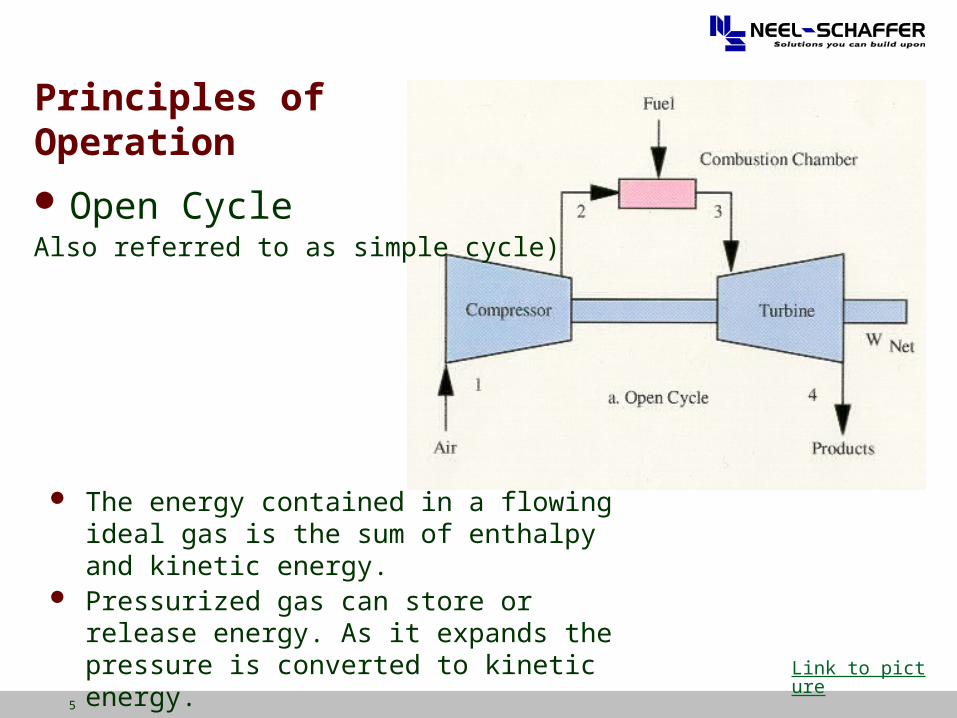
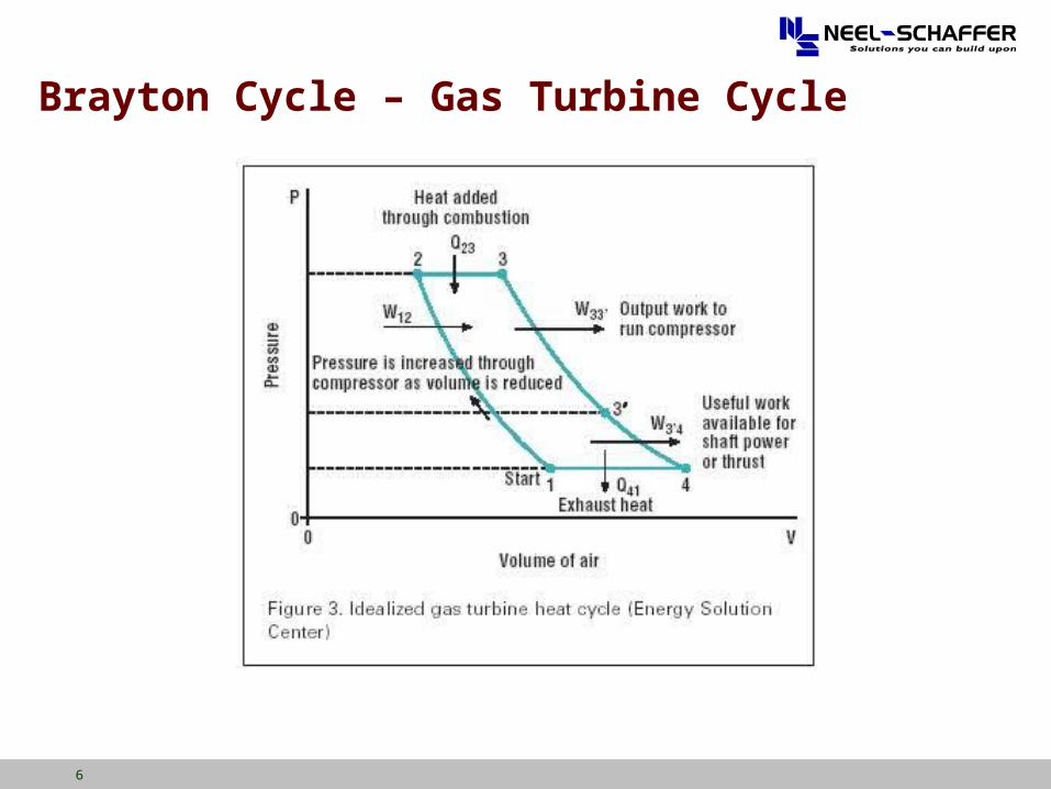
The energy contained in a flowing ideal gas is the sum of enthalpy and kinetic energy.
Pressurized gas can store or release energy. As it expands the pressure is converted to kinetic energy.
Principles ofOperation
Open CycleAlso referred to as simple cycle)
Link to picture
6
Brayton Cycle – Gas Turbine Cycle
7
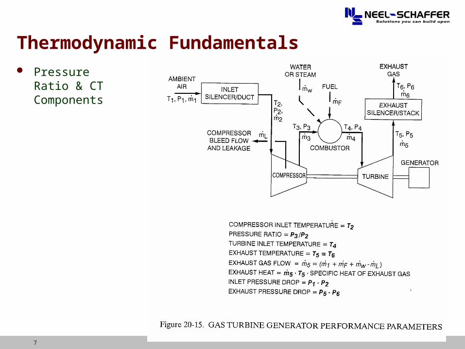
Thermodynamic Fundamentals Pressure Ratio &
CT Components
8
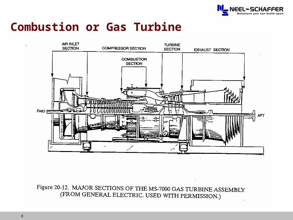
Combustion or Gas Turbine
9
Principles of Operation
Compressor As air flows into the compressor, energy is transferred from its
rotating blades to the air. Pressure and temperature of the air increase.
Most compressors operate in the range of 75% to 85% efficiency.
Combustor The purpose of the combustor is to increase the energy stored in
the compressor exhaust by raising its temperature.
Turbine The turbine acts like the compressor in reverse with respect to
energy transformation.
Most turbines operate in the range of 80% to 90% efficiency.
10
Principles of Operation Overall Energy Transformations (Thermal Efficiency)
Useful Work = Energy released in turbine minus energy absorbed by compressor.
The compressor requires typically approximately 50% of the energy released by the turbine.
Overall Thermal Efficiency = Useful Work/Fuel Chemical Energy *100
Typical overall thermal efficiencies of a combustion turbine are 20% - 40%.
11
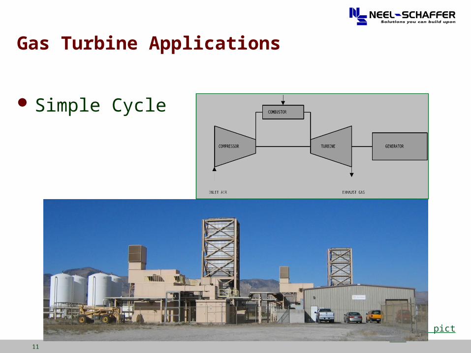
Gas Turbine Applications
Simple Cycle
Link to picture
12
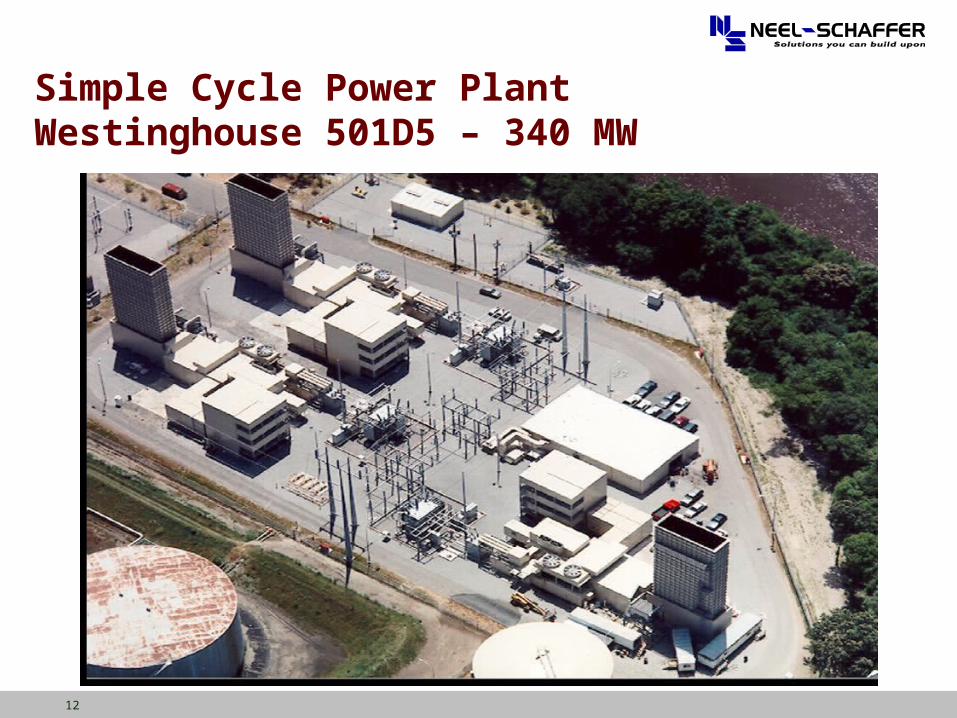
Simple Cycle Power PlantWestinghouse 501D5 – 340 MW
13
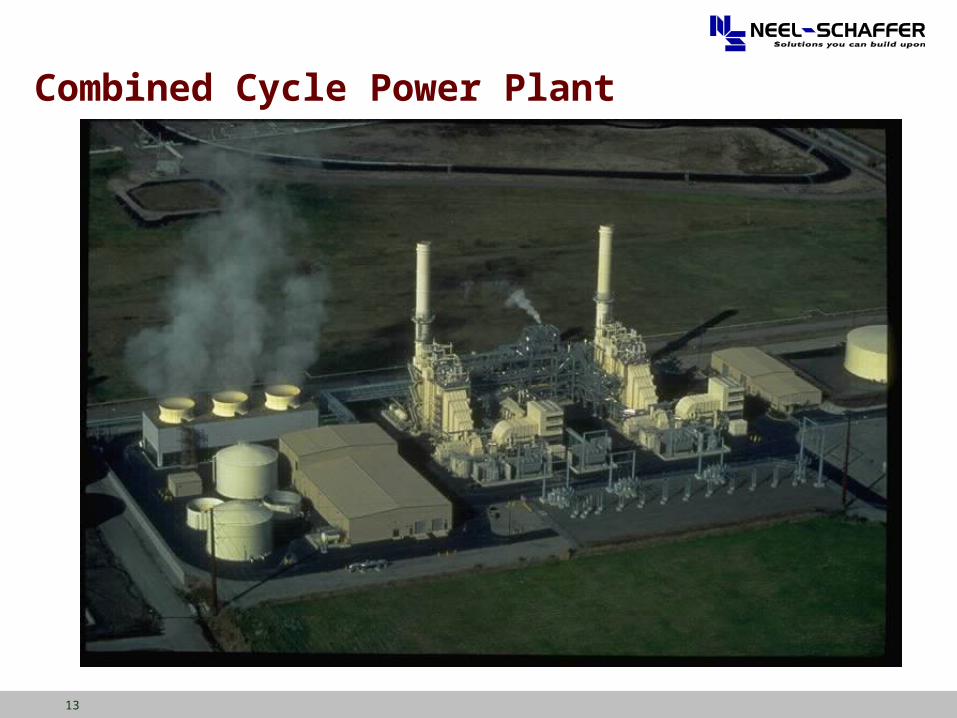
Combined Cycle Power Plant
14
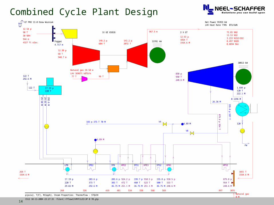
Combined Cycle Plant DesignGT PRO 13.0 Drew Wozniak
1512 10-13-2004 23:27:31 file=C:\Tflow13\MYFILES\3P 0 70.gtp
Net Power 95959 kWLHV Heat Rate 7705 BTU/kWh
p[psia], T[F], M[kpph], Steam Properties: Thermoflow - STQUIK
4.717 m Fogger
1X GE 6581B 2 X GT
33781 kW
12.54 p 90 T 30 %RH 944 m 4327 ft elev.
12.39 p 68 T 948.7 m
Natural gas 18.58 m
96 T 77 TLHV 369671 kBTU/h
149.2 p 684 T
143.2 p 2072 T
967.3 m
12.93 p 1034 T 1934.6 M
73.85 %N2 13.53 %O2 3.233 %CO2+SO2 8.497 %H2O 0.8894 %Ar
1031 T 1934.6 M
1031 897 569 568 538 534 481 419 326 268
268 T 1934.6 M
30813 kW
0.1296 M
FW
1.694 p 120 T 222.1 M
120 T
Natural gas 0 M
122 T 292.6 M
122 T 17.19 p 220 T
29.58 M
17.19 p 220 T 29.65 M
LPB
29.65 M 292.6 M
203.6 p 373 T 292.6 M
IPE2
203.6 p 383 T 36.75 M
IPB
199.7 p 460 T 36.75 M
IPS1
195.8 p 500 T 36.75 M
IPS2
924.2 p 472 T 251.1 M
HPE2
910.5 p 523 T 251.1 M
HPE3
910.5 p 533 T 248.6 M
HPB1
879.8 p 954 T 248.6 M
HPS3
850 p 950 T 248.6 M
879.8 p 954 T
6.89 M
183 p 375 T 70 M V4
26.36 M 195.8 p 597 T
V8
6.89 M
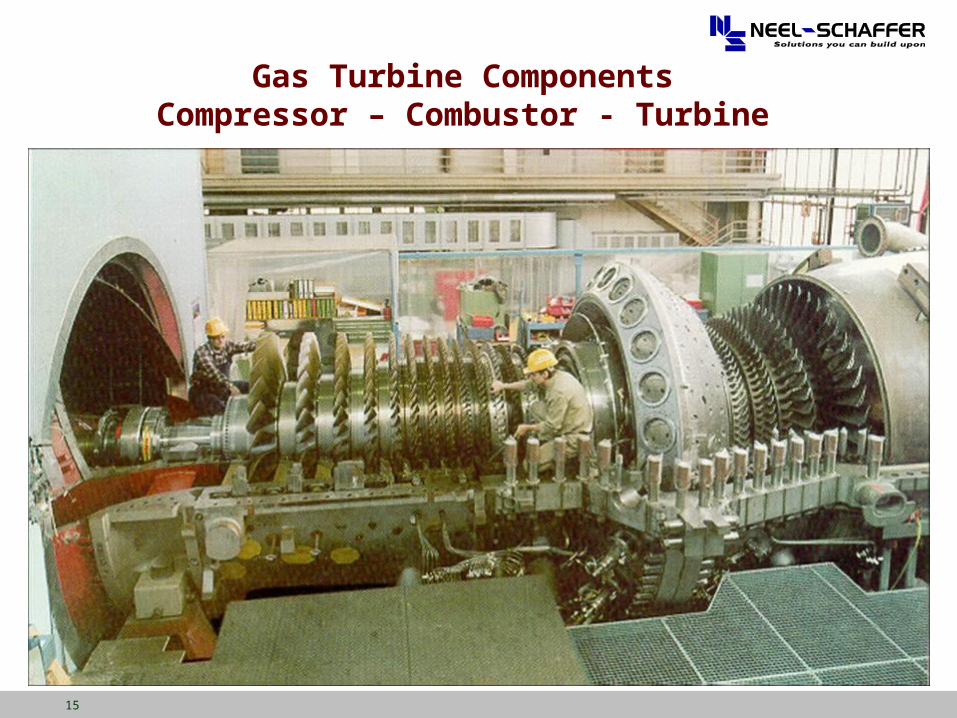
15
Gas Turbine ComponentsCompressor – Combustor - Turbine
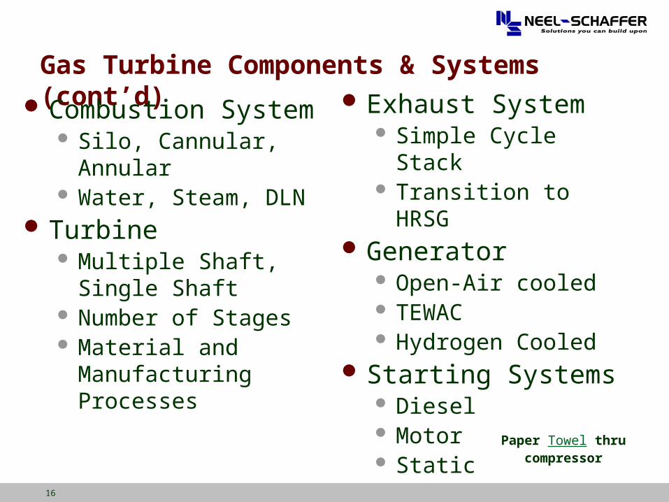
16
Gas Turbine Components & Systems (cont’d)
Combustion System Silo, Cannular, Annular Water, Steam, DLN
Turbine Multiple Shaft, Single
Shaft Number of Stages Material and
Manufacturing Processes
Exhaust System Simple Cycle Stack Transition to HRSG
Generator Open-Air cooled TEWAC Hydrogen Cooled
Starting Systems Diesel Motor Static
Paper Towel thru compressor
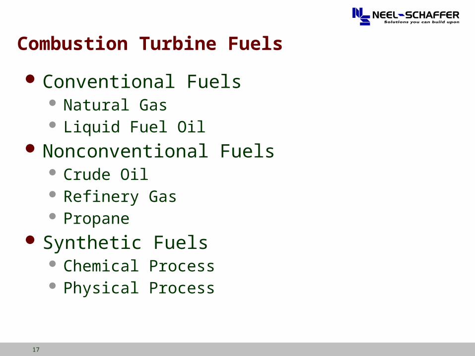
17
Combustion Turbine Fuels
Conventional Fuels Natural Gas Liquid Fuel Oil
Nonconventional Fuels Crude Oil Refinery Gas Propane
Synthetic Fuels Chemical Process Physical Process
18
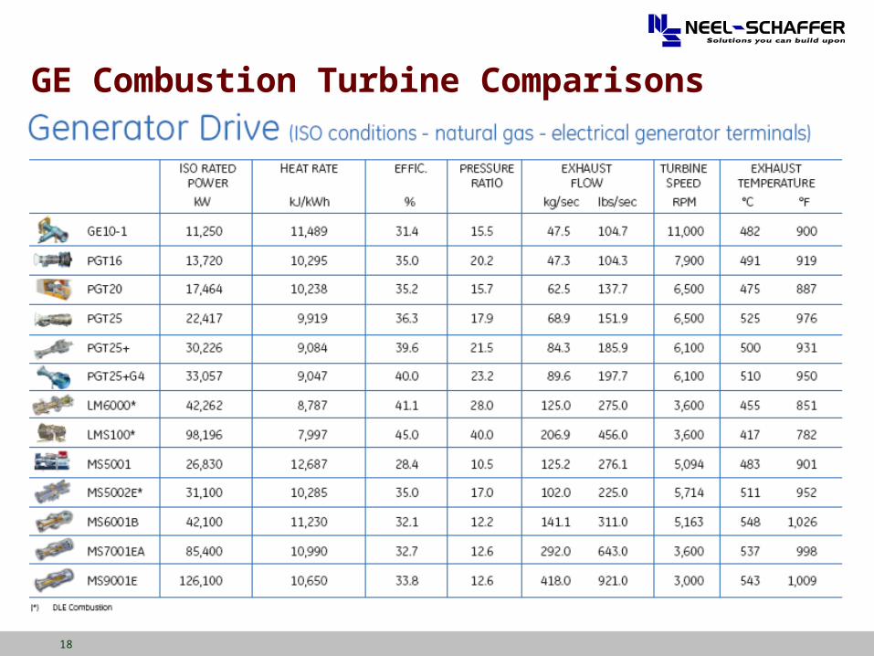
GE Combustion Turbine Comparisons
19
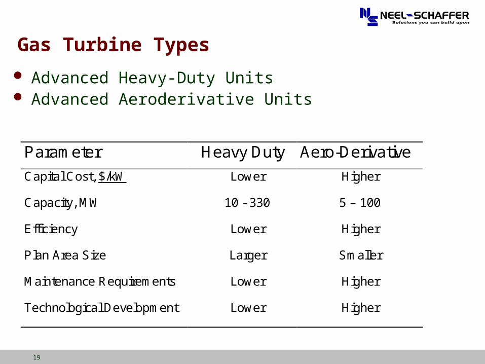
Parameter Heavy Duty Aero-Derivative
Capital Cost, $/kW Lower Higher
Capacity, MW 10 - 330 5 – 100
Efficiency Lower Higher
Plan Area Size Larger Smaller
Maintenance Requirements Lower Higher
Technological Development Lower Higher
Advanced Heavy-Duty Units Advanced Aeroderivative Units
Gas Turbine Types
20
Gas Turbine Major Sections
Air Inlet Compressor Combustion System Turbine Exhaust Support Systems
21
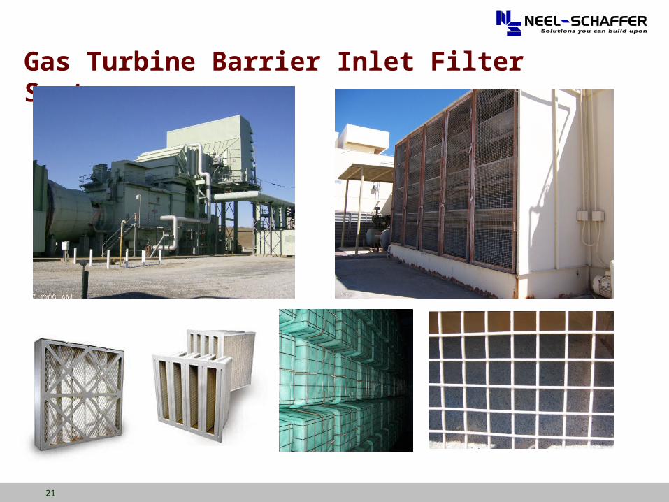
Gas Turbine Barrier Inlet Filter Systems
22
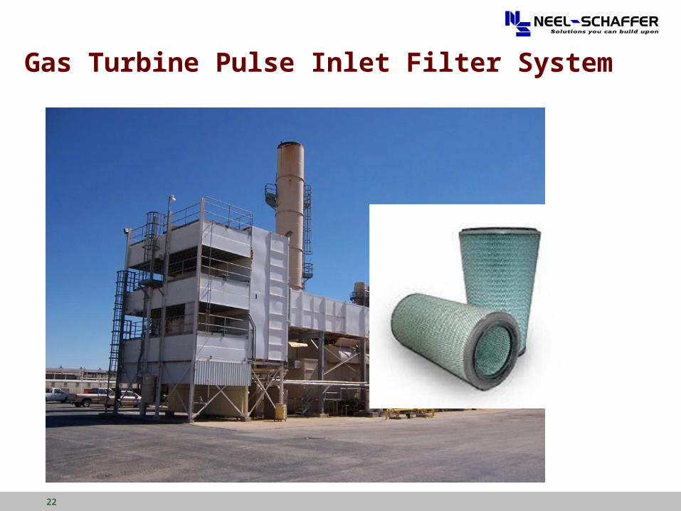
Gas Turbine Pulse Inlet Filter System
23
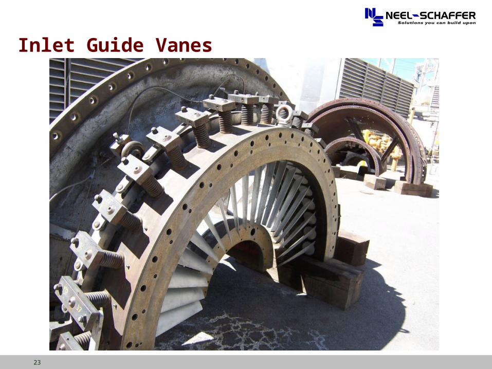
Inlet Guide Vanes
24
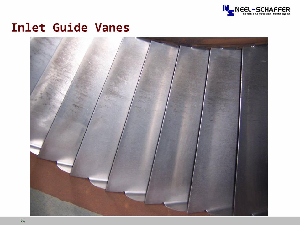
Inlet Guide Vanes
25
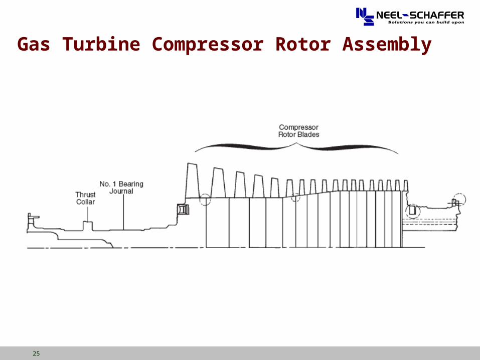
Gas Turbine Compressor Rotor Assembly
26
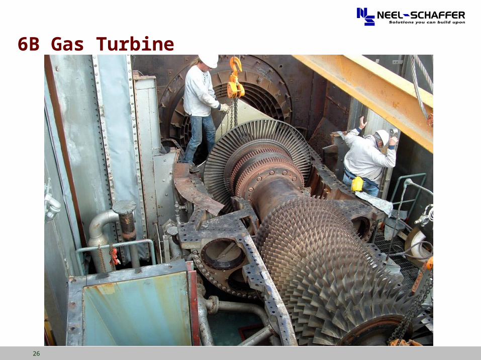
6B Gas Turbine
27
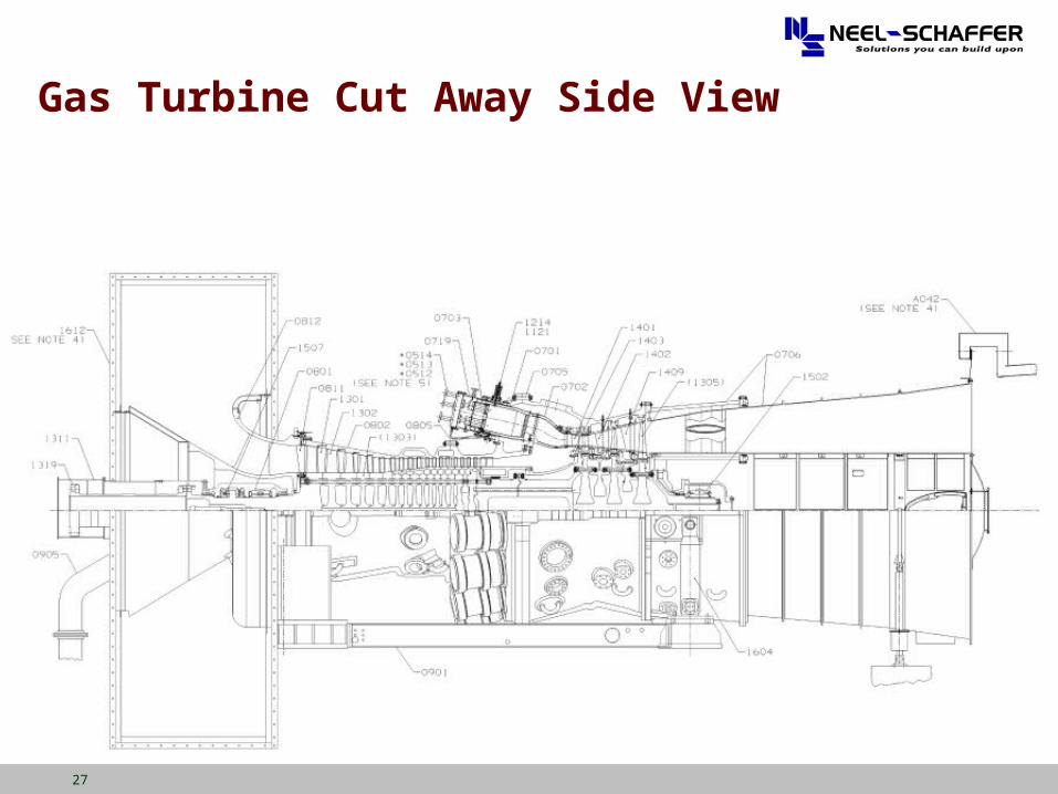
Gas Turbine Cut Away Side View
28
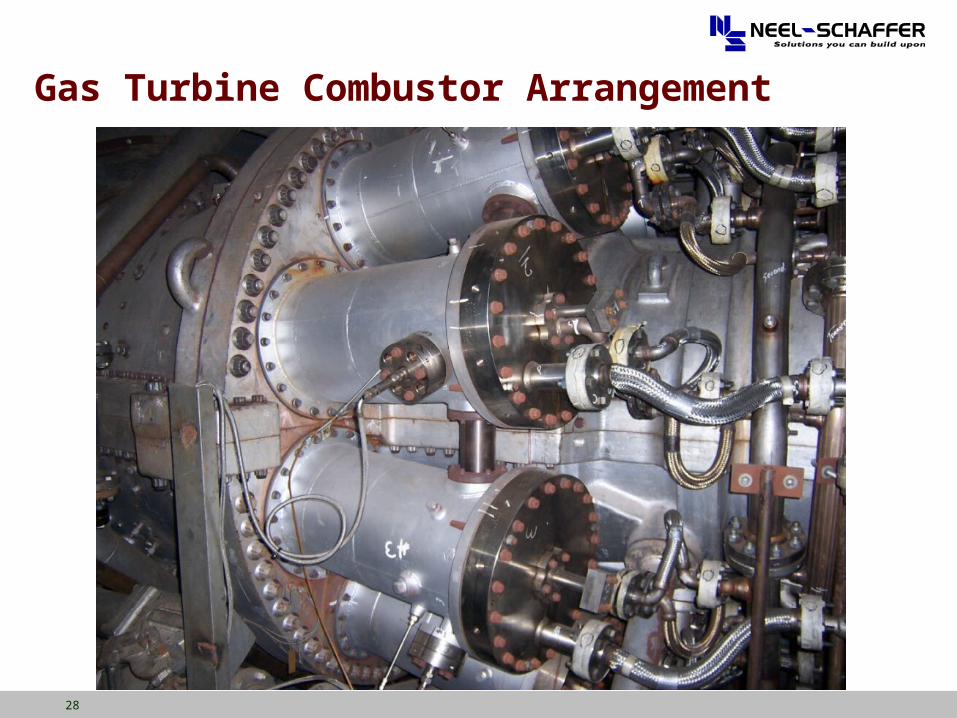
Gas Turbine Combustor Arrangement
29
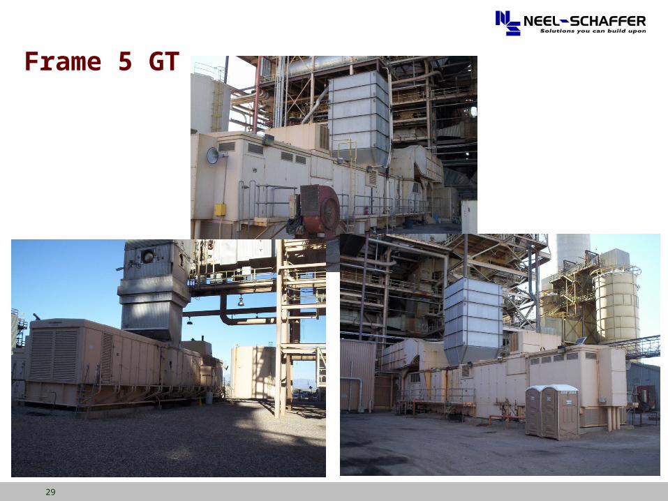
Frame 5 GT
30
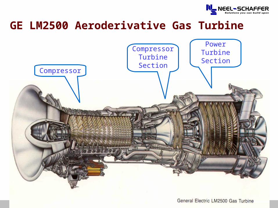
GE LM2500 Aeroderivative Gas Turbine
Compressor
Compressor Turbine Section
Power Turbine Section
31
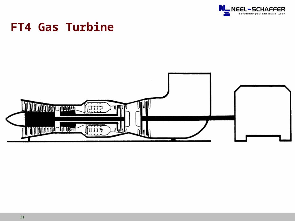
FT4 Gas Turbine
32
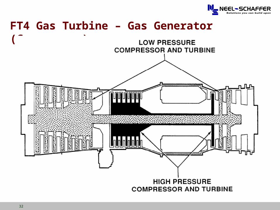
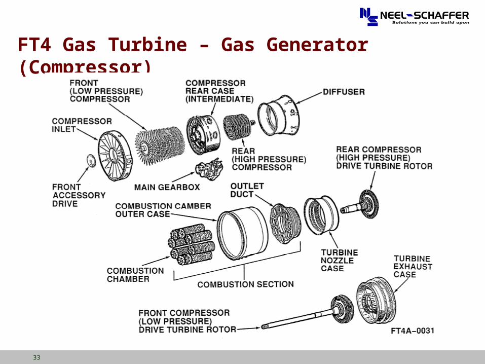
FT4 Gas Turbine – Gas Generator (Compressor)
33
FT4 Gas Turbine – Gas Generator (Compressor)
34
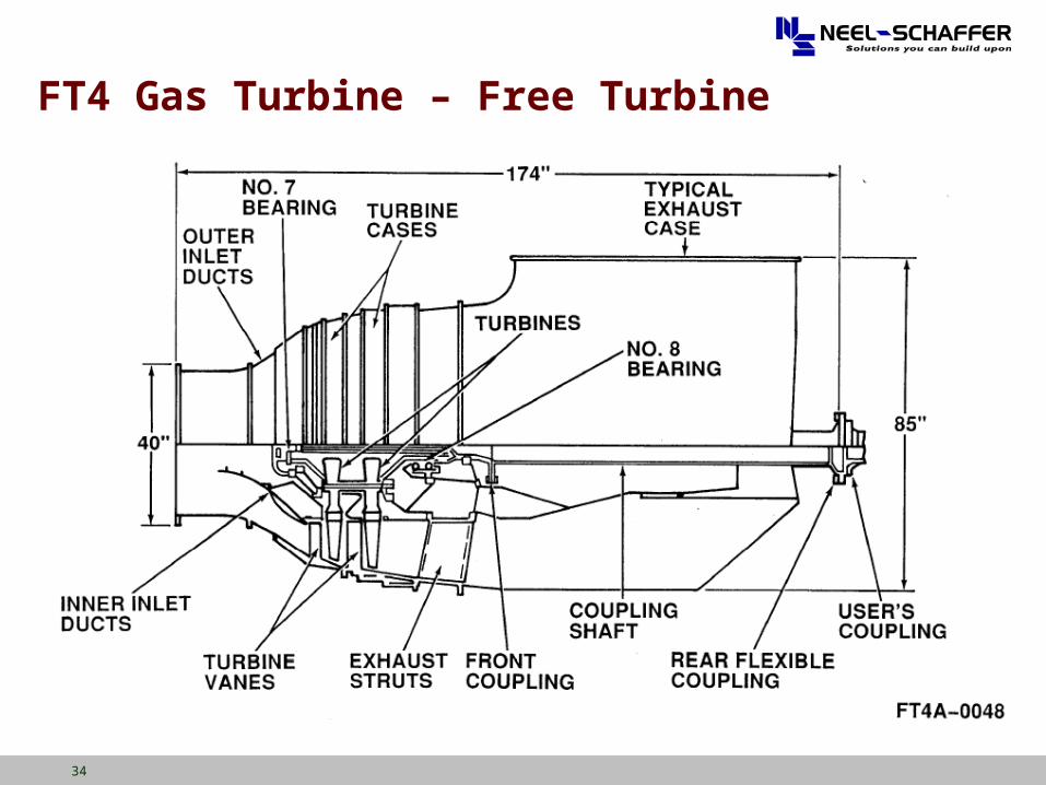
FT4 Gas Turbine – Free Turbine
35
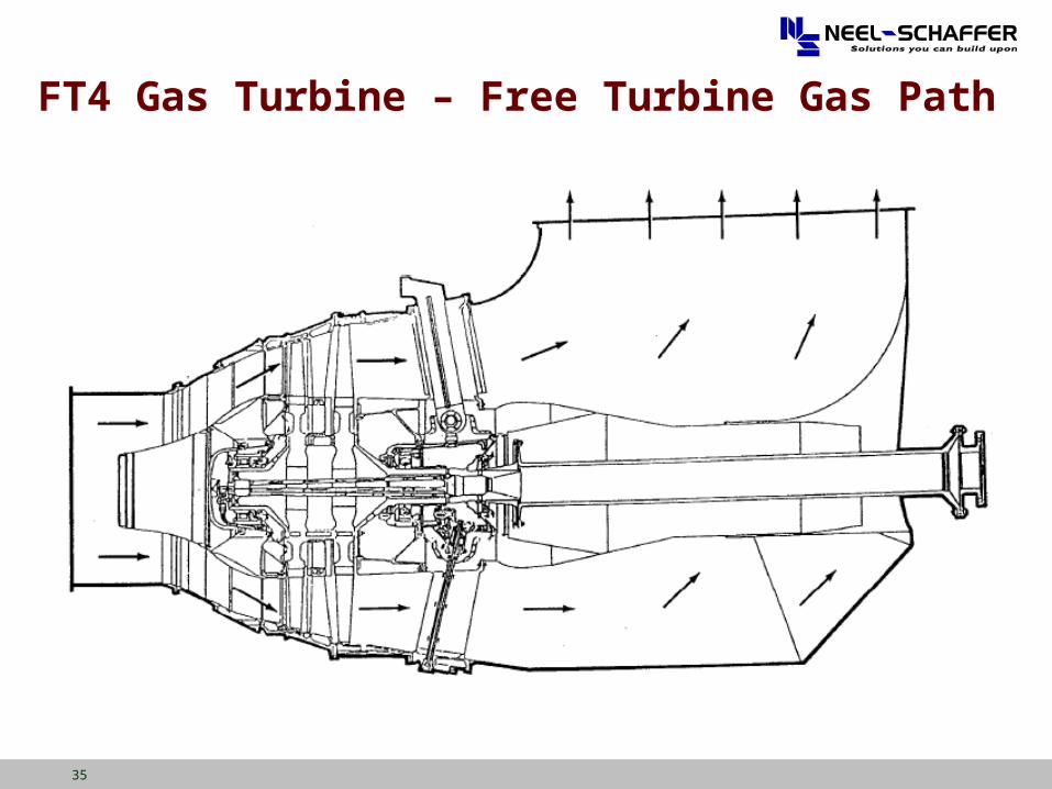
FT4 Gas Turbine – Free Turbine Gas Path
36
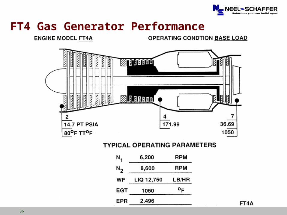
FT4 Gas Generator Performance
37
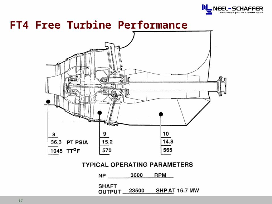
FT4 Free Turbine Performance
38
Aeroderivative Versus Heavy Duty Combustion Turbines
Aeroderivatives Higher Pressure Ratios and Firing Temperatures Result
in Higher Power Output per Pound of Air Flow Smaller Chilling/Cooling Systems Required Compressor Inlet Temperature Has a Greater Impact on
Output and Heat Rate Benefits of Chilling/Cooling Systems are More
Pronounced
39
Typical Simple Cycle CT Plant Components
Prime Mover (Combustion Turbine) Fuel Supply & Preparation Emissions Control Equipment Generator Electrical Switchgear Generator Step Up Transformer Starting System (Combustion Turbines) Auxiliary Cooling Fire Protection Lubrication System
40
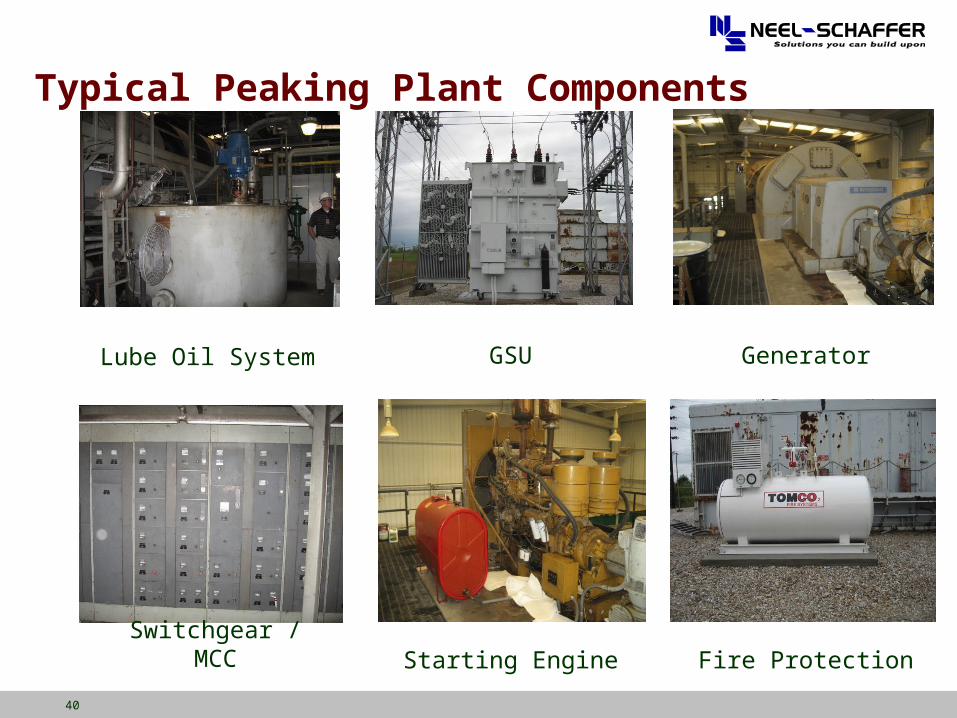
Typical Peaking Plant Components
Lube Oil System GSU Generator
Fire ProtectionStarting EngineSwitchgear / MCC
41
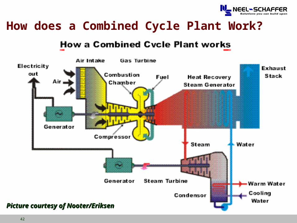
Combining the Brayton and Rankine Cycles
Gas Turbine Exhaust used as the heat source for the Steam Turbine cycle
Utilizes the major efficiency loss from the Brayton cycle Advantages:
Relatively short cycle to design, construct & commission Higher overall efficiency Good cycling capabilities Fast starting and loading Lower installed costs No issues with ash disposal or coal storage
Disadvantages High fuel costs Uncertain long term fuel source Output dependent on ambient temperature
42
Picture courtesy of Nooter/EriksenPicture courtesy of Nooter/Eriksen
How does a Combined Cycle Plant Work?
43
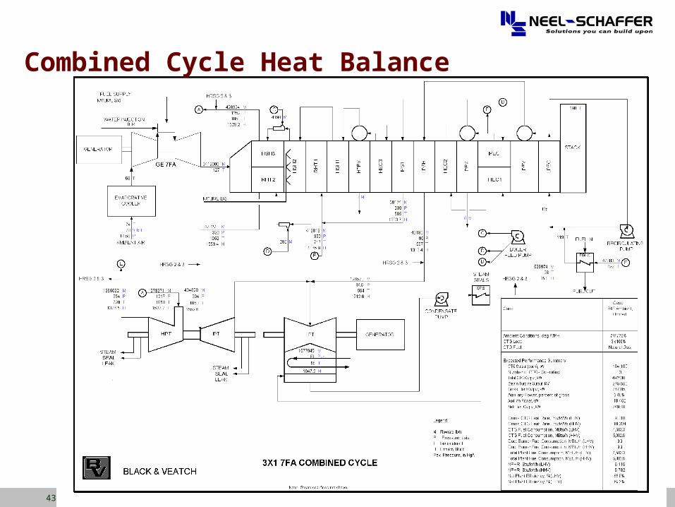
Combined Cycle Heat Balance
44
Combined Cycles Today Plant Efficiency ~ 58-60 percent
Biggest losses are mechanical input to the compressor and heat in the exhaust
Steam Turbine output Typically 50% of the gas turbine output More with duct-firing
Net Plant Output (Using Frame size gas turbines) up to 750 MW for 3 on 1 configuration Up to 520 MW for 2 on 1 configuration
Construction time about 24 months Engineering time 80k to 130k labor hours Engineering duration about 12 months Capital Cost ($900-$1100/kW) Two (2) versus Three (3) Pressure Designs
Larger capacity units utilize the additional drums to gain efficiency at the expense of higher capital costs
45
Combined Cycle Efficiency
Simple cycle efficiency (max ~ 44%*) Combined cycle efficiency (max ~58-60%*) Correlating Efficiency to Heat Rate (British Units)
= 3412/(Heat Rate) --> 3412/ = Heat Rate* Simple cycle – 3412/.44 = 7,757 Btu/Kwh* Combined cycle – 3412/.58 = 5,884 Btu/Kwh*
Correlating Efficiency to Heat Rate (SI Units) = 3600/(Heat Rate) --> 3600/ = Heat Rate* Simple cycle – 3600/.44 = 8,182 KJ/Kwh* Combined cycle – 3600/.58 = 6,207 KJ/Kwh*
Practical Values HHV basis, net output basis Simple cycle 7FA (new and clean) 10,860 Btu/Kwh (11,457 KJ/Kwh) Combined cycle 2x1 7FA (new and clean) 6,218 Btu/Kwh (6,560 KJ/Kwh)
*Gross LHV basis
46
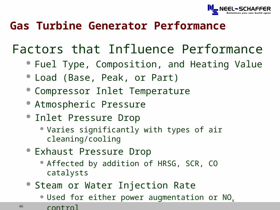
Gas Turbine Generator Performance
Factors that Influence Performance Fuel Type, Composition, and Heating Value Load (Base, Peak, or Part) Compressor Inlet Temperature Atmospheric Pressure Inlet Pressure Drop
Varies significantly with types of air cleaning/cooling
Exhaust Pressure Drop Affected by addition of HRSG, SCR, CO catalysts
Steam or Water Injection Rate Used for either power augmentation or NOx control
Relative Humidity
47
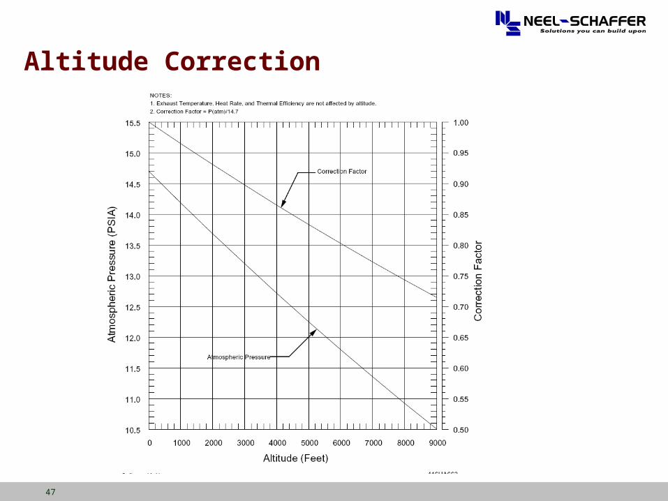
Altitude Correction
48
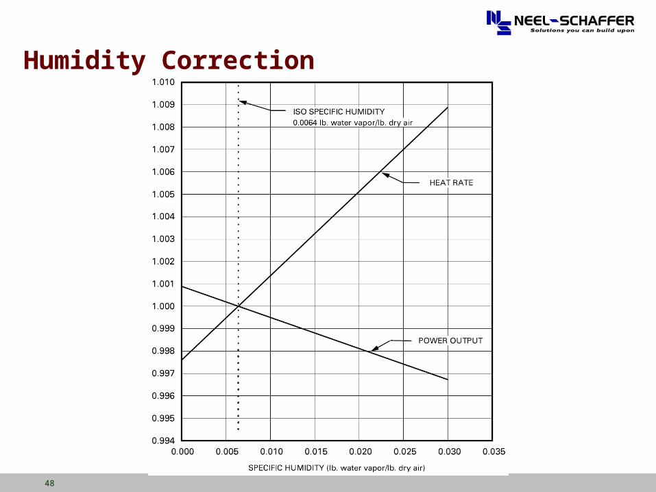
Humidity Correction
49
Cogeneration Plant
A Cogeneration Plant Power generation facility that also provides
thermal energy (steam) to a thermal host. Typical thermal hosts
paper mills, chemical plants, refineries, etc… potentially any user that uses large quantities of
steam on a continuous basis. Good applications for combined cycle plants
Require both steam and electrical power
50
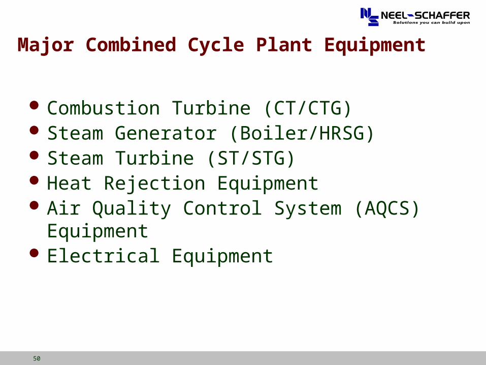
Major Combined Cycle Plant Equipment
Combustion Turbine (CT/CTG) Steam Generator (Boiler/HRSG) Steam Turbine (ST/STG) Heat Rejection Equipment Air Quality Control System (AQCS) Equipment Electrical Equipment
51
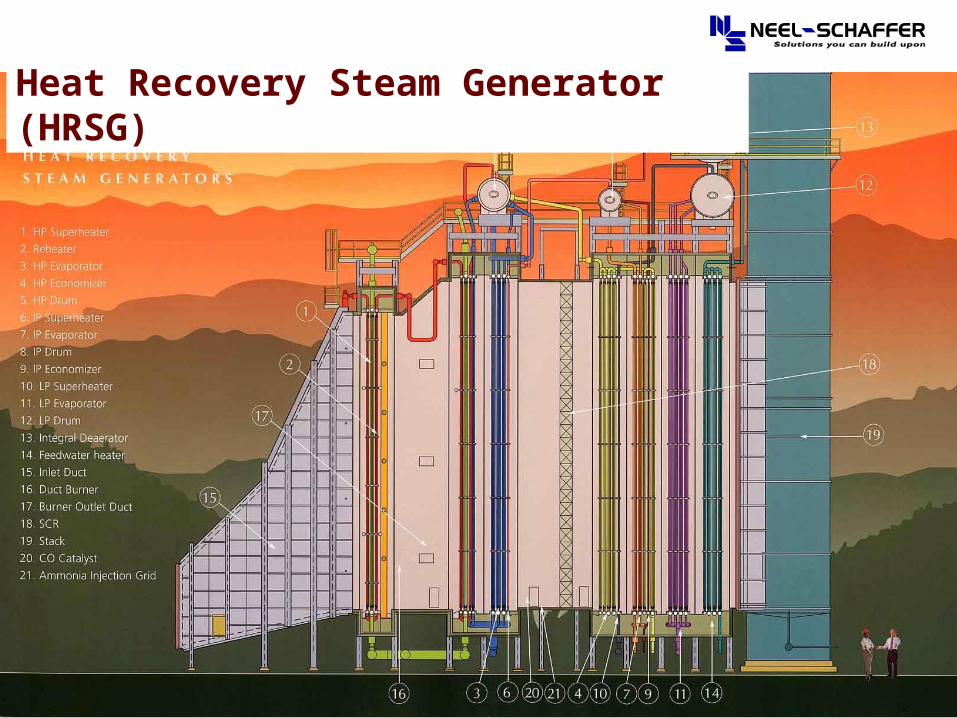
Heat Recovery Steam Generator (HRSG)
52
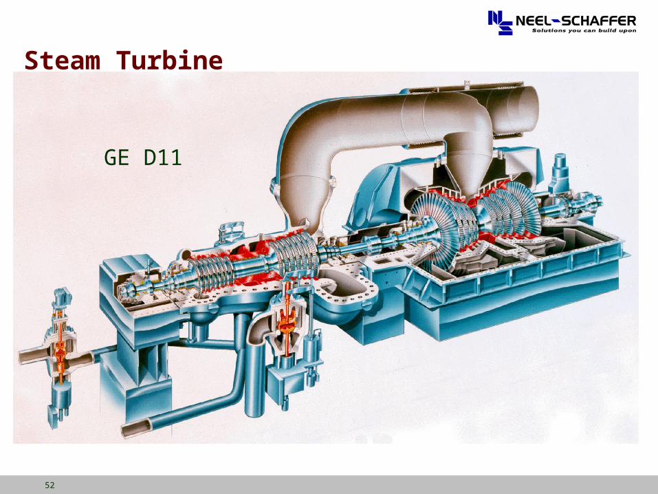
Steam Turbine
GE D11
53
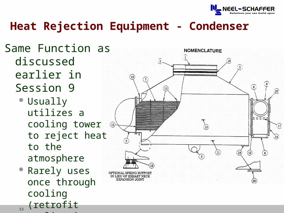
Same Function as discussed earlier in Session 9 Usually utilizes a
cooling tower to reject heat to the atmosphere
Rarely uses once through cooling (retrofit applications or ocean)
Heat Rejection Equipment - Condenser