Embed Size (px)
Citation preview
8 April 2003
MineSight® Foregroundin the
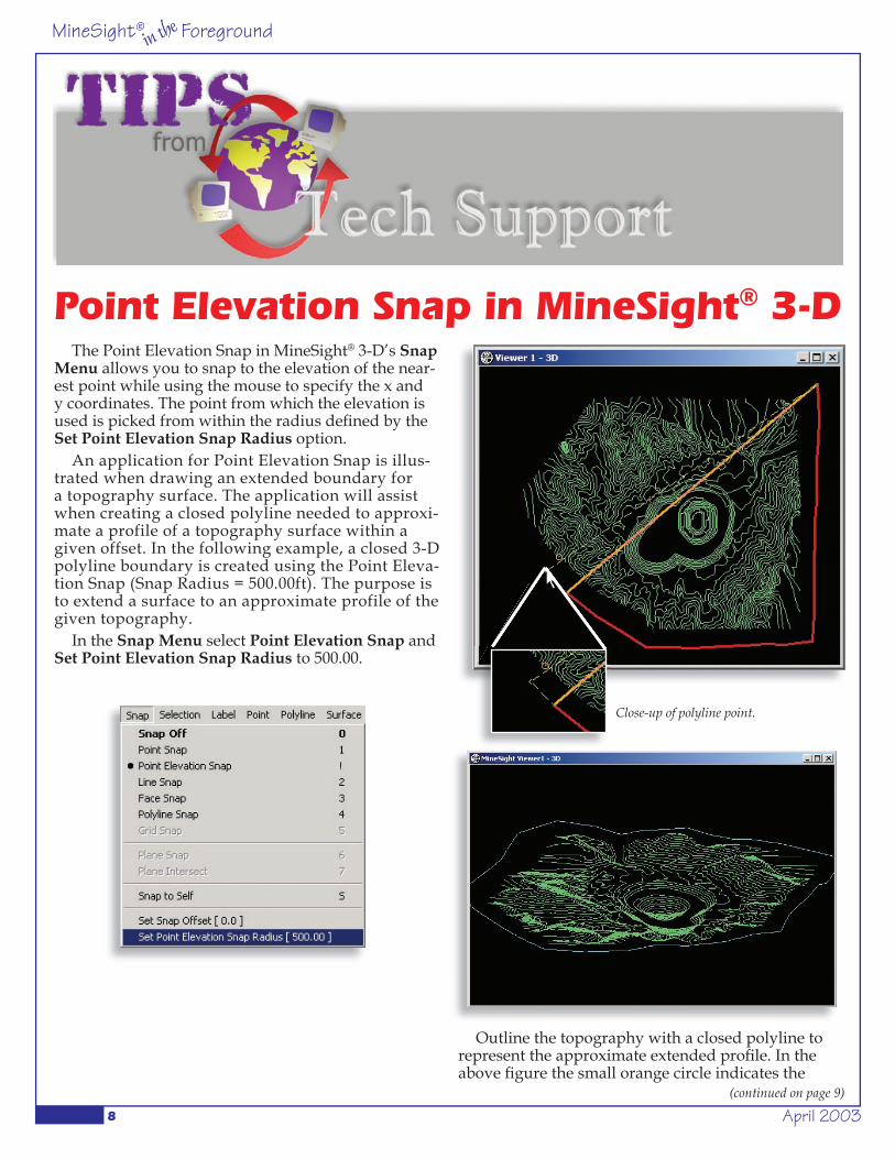
The Point Elevation Snap in MineSight® 3-D’s Snap Menu allows you to snap to the elevation of the near-est point while using the mouse to specify the x and y coordinates. The point from which the elevation is used is picked from within the radius defi ned by the Set Point Elevation Snap Radius option.
An application for Point Elevation Snap is illus-trated when drawing an extended boundary for a topography surface. The application will assist when creating a closed polyline needed to approxi-mate a profile of a topography surface within a given offset. In the following example, a closed 3-D polyline boundary is created using the Point Eleva-tion Snap (Snap Radius = 500.00ft). The purpose is to extend a surface to an approximate profile of the given topography.
In the Snap Menu select Point Elevation Snap and Set Point Elevation Snap Radius to 500.00.
Outline the topography with a closed polyline to represent the approximate extended profi le. In the above fi gure the small orange circle indicates the
(continued on page 9)
Point Elevation Snap in MineSight® 3-D
Close-up of polyline point.
April 2003 9
MineSight® Foregroundin the
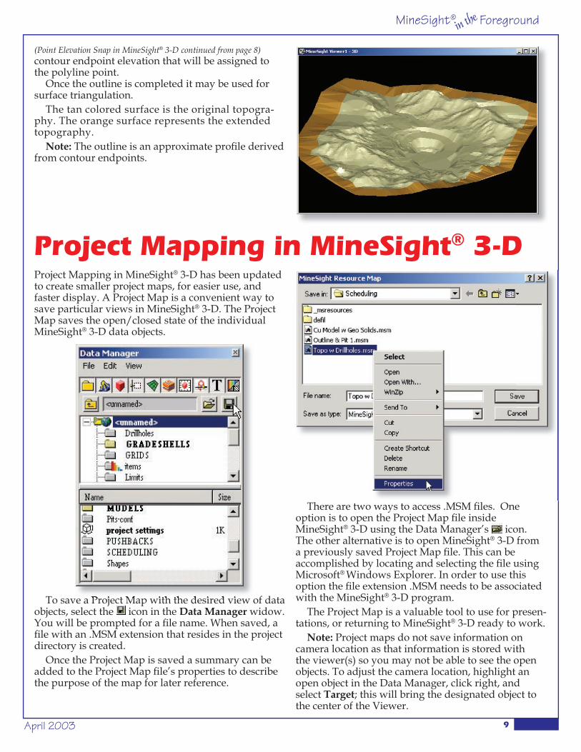
(Point Elevation Snap in MineSight® 3-D continued from page 8)contour endpoint elevation that will be assigned to the polyline point.
Once the outline is completed it may be used for surface triangulation.
The tan colored surface is the original topogra-phy. The orange surface represents the extended topography.
Note: The outline is an approximate profi le derived from contour endpoints.
Project Mapping in MineSight® 3-D has been updated to create smaller project maps, for easier use, and faster display. A Project Map is a convenient way to save particular views in MineSight® 3-D. The Project Map saves the open/closed state of the individual MineSight® 3-D data objects.
To save a Project Map with the desired view of data objects, select the icon in the Data Manager widow. You will be prompted for a fi le name. When saved, a fi le with an .MSM extension that resides in the project directory is created.
Once the Project Map is saved a summary can be added to the Project Map fi le’s properties to describe the purpose of the map for later reference.
Project Mapping in MineSight® 3-D
To save a Project Map with the desired view of data
There are two ways to access .MSM fi les. One option is to open the Project Map fi le inside MineSight® 3-D using the Data Manager’s icon. The other alternative is to open MineSight® 3-D from a previously saved Project Map fi le. This can be accomplished by locating and selecting the fi le using Microsoft® Windows Explorer. In order to use this option the fi le extension .MSM needs to be associated with the MineSight® 3-D program.
The Project Map is a valuable tool to use for presen-tations, or returning to MineSight® 3-D ready to work.
Note: Project maps do not save information on camera location as that information is stored with the viewer(s) so you may not be able to see the open objects. To adjust the camera location, highlight an open object in the Data Manager, click right, and select Target; this will bring the designated object to the center of the Viewer.