Embed Size (px)
Citation preview
MSA-20 User Guide Version 3.1
1
MSA-20
USER GUIDE
VERSION 3.1 Author: Andy Whitaker
Mark Roberts Motion Control Ltd. www.mrmoco.com
Unit 4 Birches Industrial Estate, [email protected] Imberhorne Lane, Tel: +44-1342-334700
East Grinstead, Fax: +44-1342-334701
West Sussex, RH19 1XZ,
England
Copyright 2006-2008 MRMC
Updated July 2008
MSA-20 User Guide Version 3.1
MSA-20 User Guide Version 3.1
2
Contents
1 Introduction ............................................................................................................................................................. 6 1.1 Standalone System Features .............................................................................................................................. 6
1.1.1 Record and Playback ......................................................................................................................... 7 1.1.2 Back-Pan........................................................................................................................................... 7 1.1.3 Timelapse ......................................................................................................................................... 7 1.1.4 Preston Controls ................................................................................................................................ 7 1.1.5 Move Archiving ................................................................................................................................ 7
1.2 Flair System Features ........................................................................................................................................ 8 2 The Standalone User Interface ................................................................................................................................ 9
2.1 Buttons ............................................................................................................................................................. 9 2.1.1 Select Button/Jog Dial............................................................................................................................... 9 2.1.2 Back Button .............................................................................................................................................. 9 2.1.3 The Camera Button ................................................................................................................................... 9 2.1.4 The E-Stop Button .................................................................................................................................... 9
2.2 Menu System Overview .................................................................................................................................. 10 2.3 Top Level Display ........................................................................................................................................... 11
1.1.6 System Ready ................................................................................................................................. 11 1.1.7 Camera Running.............................................................................................................................. 11 1.1.8 Ulti-Head Load Fail......................................................................................................................... 11 1.1.9 Home All Axes................................................................................................................................ 11
2.4 Information Messages ..................................................................................................................................... 11 1.1.10 E-Stop Dropped............................................................................................................................... 11
3 The Standalone Menu System ............................................................................................................................... 12 3.1 Main Menu ..................................................................................................................................................... 12
1.1.11 Set Camera Screen .......................................................................................................................... 12 1.1.11.1 FPS ...................................................................................................................................... 12 1.1.11.2 LPF ...................................................................................................................................... 13 1.1.11.3 Enable: Continuous/Pulsed/Time-Lapse ................................................................................ 13 1.1.11.4 Camera Sync: Disabled/Ultihead/MSA Video/MSA GPI 1/Internal ....................................... 13 1.1.11.5 Camera Sync Timeout .......................................................................................................... 13
3.2 General Setup Menu ........................................................................................................................................ 14 3.3 Set Axes Menu ................................................................................................................................................ 15
1.1.12 Set Soft Limits Screen ..................................................................................................................... 15 1.1.13 Set Limit On/Off Screen .................................................................................................................. 15 1.1.14 Set Scales Screen............................................................................................................................. 15 1.1.15 Set Ratios Screen............................................................................................................................. 15 1.1.16 Set Direction Screen ........................................................................................................................ 16 1.1.17 Set Axis Max Velocity Screen ......................................................................................................... 16 1.1.18 Set Axis Max Acceleration Screen ................................................................................................... 16 1.1.19 Set Axis Feathering Screen .............................................................................................................. 16 1.1.20 Set Axis Goto Velocity Screen......................................................................................................... 16 1.1.21 Set Axis Name Screen ..................................................................................................................... 16 1.1.22 Set Axis Type Screen ...................................................................................................................... 16 1.1.23 Set Internal Axes Screen .................................................................................................................. 17
3.4 Set Inputs Menu .............................................................................................................................................. 18 1.1.24 Set Controller Screen ....................................................................................................................... 18 1.1.25 Set Panel Controls Screen ................................................................................................................ 19 1.1.26 Set Input Method Screen.................................................................................................................. 19 1.1.27 Set Input Deadzone Screen .............................................................................................................. 19 1.1.28 Set Pot Range Screen....................................................................................................................... 19
3.5 Set Back-Pan Screen ....................................................................................................................................... 20 1.1.29 BP ................................................................................................................................................... 20 1.1.30 Pan Axis: ........................................................................................................................................ 20 1.1.31 BP Axis........................................................................................................................................... 20
MSA-20 User Guide Version 3.1
3
1.1.32 BP Scale: ........................................................................................................................................ 20 3.6 Serial Setup Screen ......................................................................................................................................... 21
1.1.33 PC Backup ...................................................................................................................................... 21 1.1.34 Mobo Position Output ..................................................................................................................... 21
3.7 Set Low Level Menu (Advanced Users Only) .................................................................................................. 23 1.1.35 Set Current Limits Screen ................................................................................................................ 23 1.1.36 Set Temp Limits Screen................................................................................................................... 23 1.1.37 Set Motor Tunings Screen ............................................................................................................... 23 1.1.38 Set Motor Control Screen ................................................................................................................ 23 1.1.39 Set Max Error Screen ...................................................................................................................... 24
3.8 Home Axes Menu ........................................................................................................................................... 25 1.1.40 Home All Axes Screen .................................................................................................................... 25 1.1.41 Home Select Axis Screen ................................................................................................................ 25 1.1.42 Direct Zero Screen .......................................................................................................................... 25 1.1.43 Set Axis Home Velocity Screen ....................................................................................................... 25 1.1.44 Set Homing Power Screen ............................................................................................................... 26
3.9 Record and Playback Menu ............................................................................................................................. 27 3.10 Record Menu ................................................................................................................................................ 28
1.1.45 Select Record Axes Screen .............................................................................................................. 28 1.1.46 Record Screen ................................................................................................................................. 28
1.1.46.1 Before Recording.................................................................................................................. 28 1.1.46.2 Starting and Stopping Recording ........................................................................................... 28 1.1.46.3 Recording Time .................................................................................................................... 28 1.1.46.4 Camera Synchronization ....................................................................................................... 28
3.11 Playback Menu ............................................................................................................................................. 29 1.1.47 Select Play Move Screen ................................................................................................................. 29 1.1.48 Play Options Screen ........................................................................................................................ 29 1.1.49 Playback Screen .............................................................................................................................. 29
1.1.49.1 Ready to Goto ...................................................................................................................... 29 1.1.49.2 Goto ..................................................................................................................................... 29 1.1.49.3 Ready to Shoot ..................................................................................................................... 29 1.1.49.4 Awaiting Cam Sync .............................................................................................................. 29 1.1.49.5 Cam Sync Failed .................................................................................................................. 30 1.1.49.6 Shooting ............................................................................................................................... 30 1.1.49.7 No Move Selected ................................................................................................................ 30
3.12 Modify Screen............................................................................................................................................... 31 1.1.50 Select Play Move............................................................................................................................. 31 1.1.51 Select Modify Axes ......................................................................................................................... 31 1.1.52 The Modify Screen .......................................................................................................................... 31
3.13 Timelapse Screen .......................................................................................................................................... 33 1.1.53 Select Timelapse Play Move Screen................................................................................................. 33 1.1.54 Timelapse Options Screen ............................................................................................................... 33
1.1.54.1 Frames ................................................................................................................................. 33 1.1.54.2 Frame Time .......................................................................................................................... 33 1.1.54.3 Type ..................................................................................................................................... 33
1.1.55 Timelapse Playback Screen ............................................................................................................. 33 3.14 Delete Screen ................................................................................................................................................ 35
1.1.56 The Delete Moves Screen ................................................................................................................ 35 1.1.57 The Delete All Moves Screen .......................................................................................................... 35
3.15 Diagnose Axes Screen ................................................................................................................................... 36 1.1.58 Encoder Values ............................................................................................................................... 36 1.1.59 Axis Positions ................................................................................................................................. 36 1.1.60 A2D inputs ...................................................................................................................................... 36 1.1.61 Switch Inputs .................................................................................................................................. 36 1.1.62 Test Outputs .................................................................................................................................... 36 1.1.63 Test Serial ....................................................................................................................................... 37 1.1.64 Ulti-Head Comms ........................................................................................................................... 37 1.1.65 Restore Defaults .............................................................................................................................. 37 1.1.66 Version Information ........................................................................................................................ 37
MSA-20 User Guide Version 3.1
4
3.16 Head Diagnostics Menu................................................................................................................................. 37 1.1.67 Axis Current .................................................................................................................................... 37 1.1.68 Axis Temperature ............................................................................................................................ 37 1.1.69 Limit Inputs .................................................................................................................................... 37 1.1.70 Encoder values ................................................................................................................................ 38 1.1.71 Ulti-Head Voltage ........................................................................................................................... 38
4 PC Backup Facility ................................................................................................................................................ 39 4.1 MSA-20 Connections (For Transfer of Moves and Settings) ............................................................................ 39 4.2 Backing-Up MSA-20 Settings ......................................................................................................................... 39 4.3 Restoring MSA-20 Settings from a Backup...................................................................................................... 40 4.4 Backing-Up MSA-20 Moves ........................................................................................................................... 40 4.5 Restoring MSA-20 Moves from a Backup ....................................................................................................... 40 4.6 Updating the MSA-20 Software....................................................................................................................... 41
1.1.72 The connections for updating the MSA-20 ....................................................................................... 41 1.1.73 Power-up Sequence ......................................................................................................................... 41 1.1.74 Updating the MSA-20: .................................................................................................................... 41
5 Quick Reference Guide (Standalone) .................................................................................................................... 42 5.1 Power Supply Connections .............................................................................................................................. 42 5.2 MSA-20 Connections ...................................................................................................................................... 42 5.3 Ulti-Head Connections .................................................................................................................................... 43 5.4 Power Up (Using One Power Supply Unit) ...................................................................................................... 44 5.5 Power Up (Using Separate MSA-20 and Ulti-Head Power Supply Units) ......................................................... 44 5.6 Loading the Ulti-Head ..................................................................................................................................... 44 5.7 Homing the Ulti-Head ..................................................................................................................................... 44 5.8 Recording a Move ........................................................................................................................................... 45
1.1.75 Axis Recording Mode ...................................................................................................................... 45 1.1.76 Recording ....................................................................................................................................... 46
5.9 Playing Back a Recorded Move ....................................................................................................................... 46 1.1.77 Selecting a Move to Playback .......................................................................................................... 46 1.1.78 Playback ......................................................................................................................................... 47
5.10 Modifying a Recorded Move ......................................................................................................................... 48 1.1.79 Selecting a Move to Modify............................................................................................................. 48 1.1.80 Selecting Axes to Modify/Record .................................................................................................... 48 1.1.81 Modifying ....................................................................................................................................... 48
5.11 Using Timelapse to Play Back a Recorded Move at Slower Speeds ................................................................ 49 1.1.82 Selecting a Move for Timelapse Playback ........................................................................................ 49 1.1.83 Setting the Timelapse Playback Speed and Type .............................................................................. 49
1.1.84 Enabling the Camera Trigger when in Stop Frame Timelapse ..................................................... 49 1.1.85 Timelapse Playback ......................................................................................................................... 49
5.12 Setting Up Synchronization ........................................................................................................................... 50 5.13 Setting up the MSA-20 to Control a Camera .................................................................................................. 51
1.1.86 Assigning the Camera Controller to a Motor Axis ............................................................................ 51 1.1.87 Setting the Camera speed ................................................................................................................. 51
5.14 Using Preston Lens Motors ............................................................................................................................ 51 5.15 Using Canon Lens Controls ........................................................................................................................... 52 5.16 Wireless Head Communication ...................................................................................................................... 53
1.1.88 MSA-20 .......................................................................................................................................... 53 1.1.89 Ulti-Head ........................................................................................................................................ 53
6 Quick Reference Guide (Flair) .............................................................................................................................. 54 6.1 Power Supply Connections .............................................................................................................................. 54 6.2 Rootbox Connections ...................................................................................................................................... 54 6.3 MSA-20 Connections ...................................................................................................................................... 56 6.4 Ulti-Head Connections .................................................................................................................................... 57 6.5 Power Up ........................................................................................................................................................ 59 6.6 Using Flair ...................................................................................................................................................... 59
7 Appendix A, Connector Pin-Outs ......................................................................................................................... 60 7.1 MSA-20 Connector Pin-Outs ........................................................................................................................... 60
1.1.90 Expansion ....................................................................................................................................... 60 1.1.91 Aux 1 .............................................................................................................................................. 60
MSA-20 User Guide Version 3.1
5
1.1.92 Aux 2 .............................................................................................................................................. 60 1.1.93 Serial A ........................................................................................................................................... 61 1.1.94 Serial B ........................................................................................................................................... 61 1.1.95 Up Link........................................................................................................................................... 61 1.1.96 Down Link ...................................................................................................................................... 61 1.1.97 GPIO1............................................................................................................................................. 62 1.1.98 GPIO2............................................................................................................................................. 62 1.1.99 Video In .......................................................................................................................................... 62 1.1.100 Boot Mode ...................................................................................................................................... 62 1.1.101 Power In ......................................................................................................................................... 63 1.1.102 Power Out ....................................................................................................................................... 63
7.2 Ulti-Head Connector Pin-Outs ......................................................................................................................... 63 1.1.103 Motor (Pan/Aux2/Aux1/Tilt/Focus/Zoom) ....................................................................................... 63 1.1.104 Power .............................................................................................................................................. 63 1.1.105 Data ................................................................................................................................................ 63 1.1.106 Camera Accessory ........................................................................................................................... 63 1.1.107 Serial .............................................................................................................................................. 64
8 Appendix B, I/O Specification ............................................................................................................................... 65 8.1 GPI Specification ............................................................................................................................................ 65 8.2 GPO Specification........................................................................................................................................... 65
MSA-20 User Guide Version 3.1
6
1 Introduction
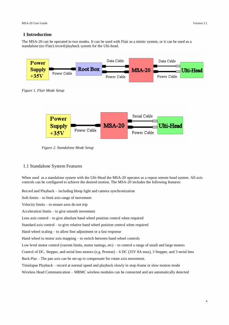
The MSA-20 can be operated in two modes. It can be used with Flair as a mimic system, or it can be used as a standalone (no Flair) record/playback system for the Ulti-head.
1.1 Standalone System Features
When used as a standalone system with the Ulti-Head the MSA-20 operates as a repeat remote head system. All axis
controls can be configured to achieve the desired motion. The MSA-20 includes the following features:
Record and Playback – including bloop light and camera synchronization
Soft-limits – to limit axis range of movement
Velocity limits – to ensure axes do not trip
Acceleration limits – to give smooth movement
Lens axis control – to give absolute hand wheel position control when required
Standard axis control – to give relative hand wheel position control when required
Hand wheel scaling – to allow fine adjustment or a fast response
Hand wheel to motor axis mapping – to switch between hand wheel controls
Low level motor control (current limits, motor tunings, etc) – to control a range of small and large motors
Control of DC, Stepper, and serial lens motors (e.g. Preston) – 6 DC (35V 8A max), 3 Stepper, and 3 serial lens
Back-Pan – The pan axis can be set-up to compensate for rotate axis movement.
Timelapse Playback – record at normal speed and playback slowly in stop-frame or slow motion mode
Wireless Head Communication – MRMC wireless modules can be connected and are automatically detected
Figure 2. Standalone Mode Setup
Figure 1. Flair Mode Setup
MSA-20 User Guide Version 3.1
7
1.1.1 Record and Playback
The MSA-20 can record moves to internal Flash memory. Up to 2.9 axis hours of move data can be recorded (e.g. If
recording 3 axes the maximum recording time would be 58 minutes). These moves can then be played back any number
of times.
Each Ulti-Head axis can be set to one of the following record modes
1. Record – The axis movement is saved to flash memory when recording starts.
2. Live – The axis can be moved during record and playback but the movement is not recorded.
3. Ignore – The axis holds position during recording and playback and is not recorded.
4. Learn – The axis can be backdriven and the movement is recorded for playback.
The start position of all axes is recorded ensuring that playback always starts in the same position every time. Recording
and playback can be synchronized to a camera exposure pulse if required. A bloop light is triggered at the start and end
of recording to assist when editing.
1.1.2 Back-Pan
The Pan axis position can be modified by another axis position (.e.g. Rotate) as well as a controlling hand wheel.
A typical application uses an encoder on a rotate axis to allow the MSA-20 to measure the rotate position, this position
is then scaled such that the Pan axis is moved so it remains parallel to its original position when no hand wheel change
is applied. The hand wheel is used to offset the Pan axis relative to the parallel position.
1.1.3 Timelapse
A recorded move can be played back at a slower speed. There are 2 timelapse playback options:
1. Slow Motion – The head moves continuously at the selected speed.
2. Stop Frame – The head will perform a goto at each frame and hold position while the frame is exposed.
When using “Stop Frame” a camera trigger pulse can be generated at each frame to start the exposure.
1.1.4 Preston Controls
The Preston lens control system can be used with the MSA-20 to give record and playback of Preston lens motors.
The Preston MDR2 is connected to the Ulti-Head via a serial cable. The user then has control of the Preston lens motors
via the Preston Hand Unit. A move can be recorded in the normal way with the MSA-20 hand wheels controlling the
head axes and the Preston Hand Unit controlling the Preston lens axes. When the MSA-20 is playing back the move, it
takes control of the Preston Lens motors and plays back the recorded positions. When exiting playback, control of the
Preston lens motors is returned to the Preston Hand Unit.
1.1.5 Move Archiving
Recorded moves stored in the MSA-20 Flash memory can be transferred to a PC using the MRMC Move Archiver Utility. The MSA-20 connects to the PC via a standard PC serial cable (RS232)on the second serial port (Serial B). The
MSA-20 acts a slave device responding to requests from the PC. Each move is saved to a separate move file, this can
then be imported into other applications for further processing. The MRMC utility MC Tools can be used to convert the
move data between formats for different applications.
MSA-20 User Guide Version 3.1
8
Move files can also be transferred to the MSA-20 for playback. When creating such move file it is important that the
correct axis names are used and that they are unique as it is the axis name that is used to determine which axis the data
should be allocated to.
The MSA-20 settings can also be transferred to and from the PC for configuration backups.
1.2 Flair System Features
When operating in Flair mode the MSA-20 acts as a mimic hand wheel system. Flair is responsible for using the hand
wheel position data to control the Ulti-Head.
Note: For the system to work with Flair the Serial cable must be disconnected from the Ulti-Head at the Ulti-
Head elbow.
MSA-20 User Guide Version 3.1
9
2 The Standalone User Interface
The user interface consists of an LCD display, 4 buttons, and a jog dial. This user interface does not function when in Flair mode, with the exception of the back button which can be used to select between 'Wheel 3' and the 'Zoom' port as
a controller for the 3rd Mimic axis.
2.1 Buttons
2.1.1 Select Button/Jog Dial
Press this to access the menu and sub menus and to adjust the MSA-20 settings. Rotating the jog dial moves the
current menu selection or changes the currently selected item when adjusting settings.
2.1.2 Back Button
Use this to return to the previous menu, and cancel changes to MSA-20 settings.
2.1.3 The Camera Button
Use this to start and stop the camera
2.1.4 The E-Stop Button
Use this to stop the Ulti-Head. A single press stops any axis movement, and a double press disables all axes. Pressing
the Camera and E-Stop buttons simultaneously re-enables the Ulti-Head axes.
MSA-20 User Guide Version 3.1
10
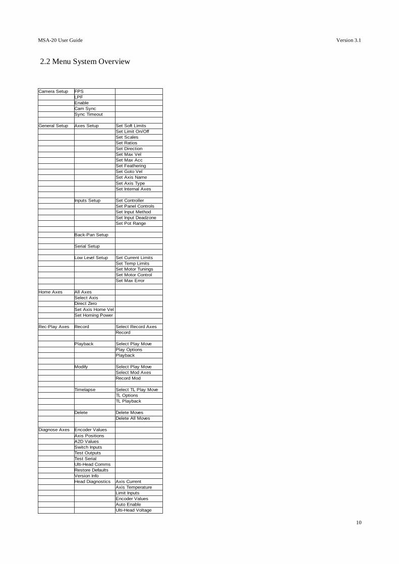
2.2 Menu System Overview
Camera Setup FPS
LPF
Enable
Cam Sync
Sync Timeout
General Setup Axes Setup Set Soft Limits
Set Limit On/Off
Set Scales
Set Ratios
Set Direction
Set Max Vel
Set Max Acc
Set Feathering
Set Goto Vel
Set Axis Name
Set Axis Type
Set Internal Axes
Inputs Setup Set Controller
Set Panel Controls
Set Input Method
Set Input Deadzone
Set Pot Range
Back-Pan Setup
Serial Setup
Low Level Setup Set Current Limits
Set Temp Limits
Set Motor Tunings
Set Motor Control
Set Max Error
Home Axes All Axes
Select Axis
Direct Zero
Set Axis Home Vel
Set Homing Power
Rec-Play Axes Record Select Record Axes
Record
Playback Select Play Move
Play Options
Playback
Modify Select Play Move
Select Mod Axes
Record Mod
Timelapse Select TL Play Move
TL Options
TL Playback
Delete Delete Moves
Delete All Moves
Diagnose Axes Encoder Values
Axis Positions
A2D Values
Switch Inputs
Test Outputs
Test Serial
Ulti-Head Comms
Restore Defaults
Version Info
Head Diagnostics Axis Current
Axis Temperature
Limit Inputs
Encoder Values
Auto Enable
Ulti-Head Voltage
MSA-20 User Guide Version 3.1
11
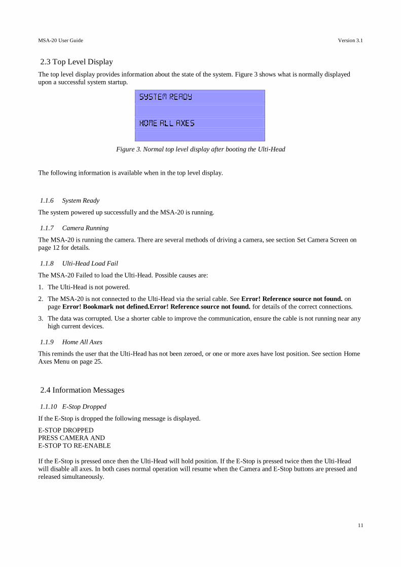
2.3 Top Level Display
The top level display provides information about the state of the system. Figure 3 shows what is normally displayed
upon a successful system startup.
Figure 3. Normal top level display after booting the Ulti-Head
The following information is available when in the top level display.
1.1.6 System Ready
The system powered up successfully and the MSA-20 is running.
1.1.7 Camera Running
The MSA-20 is running the camera. There are several methods of driving a camera, see section Set Camera Screen on
page 12 for details.
1.1.8 Ulti-Head Load Fail
The MSA-20 Failed to load the Ulti-Head. Possible causes are:
1. The Ulti-Head is not powered.
2. The MSA-20 is not connected to the Ulti-Head via the serial cable. See Error! Reference source not found. on
page Error! Bookmark not defined.Error! Reference source not found. for details of the correct connections.
3. The data was corrupted. Use a shorter cable to improve the communication, ensure the cable is not running near any
high current devices.
1.1.9 Home All Axes
This reminds the user that the Ulti-Head has not been zeroed, or one or more axes have lost position. See section Home
Axes Menu on page 25.
2.4 Information Messages
1.1.10 E-Stop Dropped
If the E-Stop is dropped the following message is displayed.
E-STOP DROPPED PRESS CAMERA AND
E-STOP TO RE-ENABLE
If the E-Stop is pressed once then the Ulti-Head will hold position. If the E-Stop is pressed twice then the Ulti-Head
will disable all axes. In both cases normal operation will resume when the Camera and E-Stop buttons are pressed and
released simultaneously.
MSA-20 User Guide Version 3.1
12
3 The Standalone Menu System
The menu system provides access to all the MSA-20 settings and control features. This is not available when in Flair
mode.
3.1 Main Menu
Figure 4. Main Menu
Pressing the select button when in the top level display opens the main menu. From here you can access the following sub-menus:
1. Set camera
2. Set Axes
3. Home Axes
4. Rec-Play Axes
5. Diagnose Axes
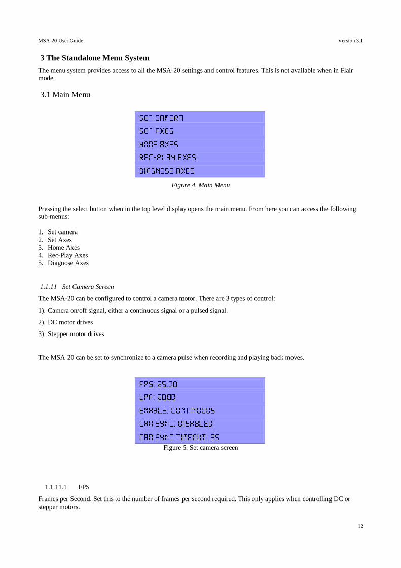
1.1.11 Set Camera Screen
The MSA-20 can be configured to control a camera motor. There are 3 types of control:
1). Camera on/off signal, either a continuous signal or a pulsed signal.
2). DC motor drives
3). Stepper motor drives
The MSA-20 can be set to synchronize to a camera pulse when recording and playing back moves.
Figure 5. Set camera screen
1.1.11.1 FPS
Frames per Second. Set this to the number of frames per second required. This only applies when controlling DC or
stepper motors.
MSA-20 User Guide Version 3.1
13
1.1.11.2 LPF
Lines per Frame. The number of encoder lines (DC motor) or steps (Stepper motor) that are required when the camera
motor rotates in order to expose 1 frame. This only applies when controlling DC or stepper motors.
1.1.11.3 Enable: Continuous/Pulsed/Time-Lapse
The enable mode of the camera being used. There are three options:
Continuous - Enable signal stays high to keep the camera on
Pulse - Generate a pulse to turn the camera on/off.
Time-Lapse – When in Time-lapse playback stop-frame mode a camera pulse is generated at the start of each frame.
1.1.11.4 Camera Sync: Disabled/Ultihead/MSA Video/MSA GPI 1/Internal
The MSA-20 can be set to synchronize record and playback to a camera synchronization pulse so that multi-pass shots
match.
There are 7 synchronization modes, these are:
1). Disabled – Record/Playabck starts without a sync pulse.
2). Ulti-Head – The Ulti-Head GPI1 input on the 'Camera Accessory' connector.
3). MSA-Video – The video input BNC connector on the MSA-20 rear panel.
4). MSA-GPI1 – The MSA-20 GPI1 input on the 'GPIO 1' connector.
5). Internal – The move is synchronized to the internal camera which is controlling either a DC or a Stepper motor
If synchronization is enabled and no camera pulse is detected the record/playback will not begin.
1.1.11.5 Camera Sync Timeout
This is the number of seconds that the MSA-20 will wait to receive a sync pulse at the start of the move. If no sync
pulse is received in this time then the move will not start and the message “Cam Sync Failed” is displayed.
Note 1: The camera must already be up to speed before record/playback is started as the MSA-20 does not check
the camera speed.
Note 2: All synchronization sources are rising edge triggered.
MSA-20 User Guide Version 3.1
14
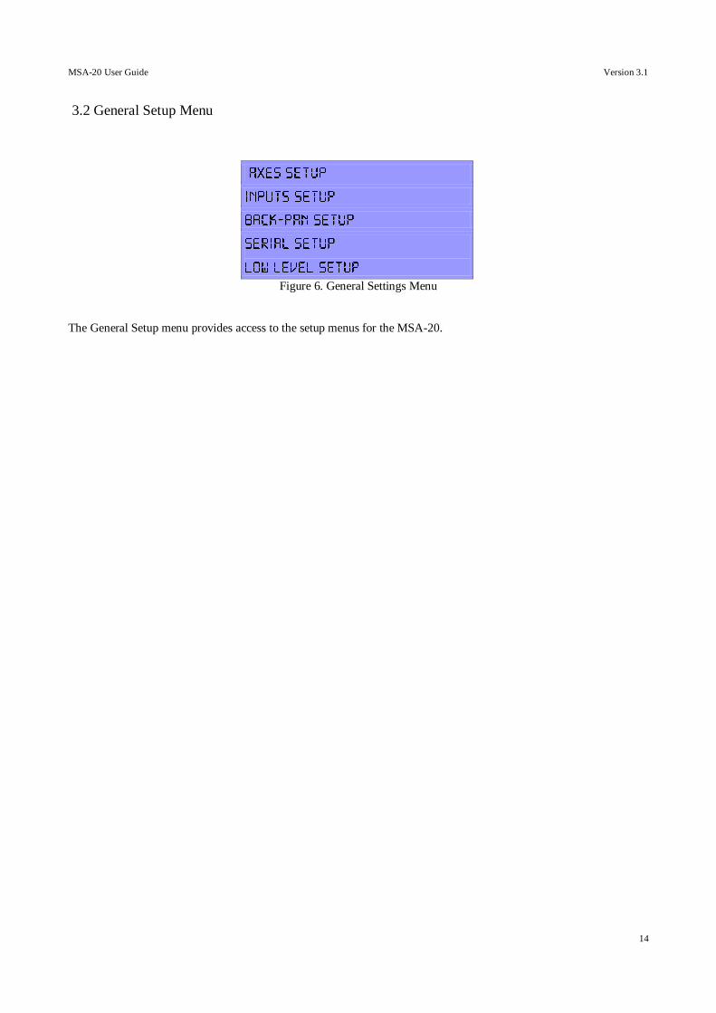
3.2 General Setup Menu
Figure 6. General Settings Menu
The General Setup menu provides access to the setup menus for the MSA-20.
MSA-20 User Guide Version 3.1
15
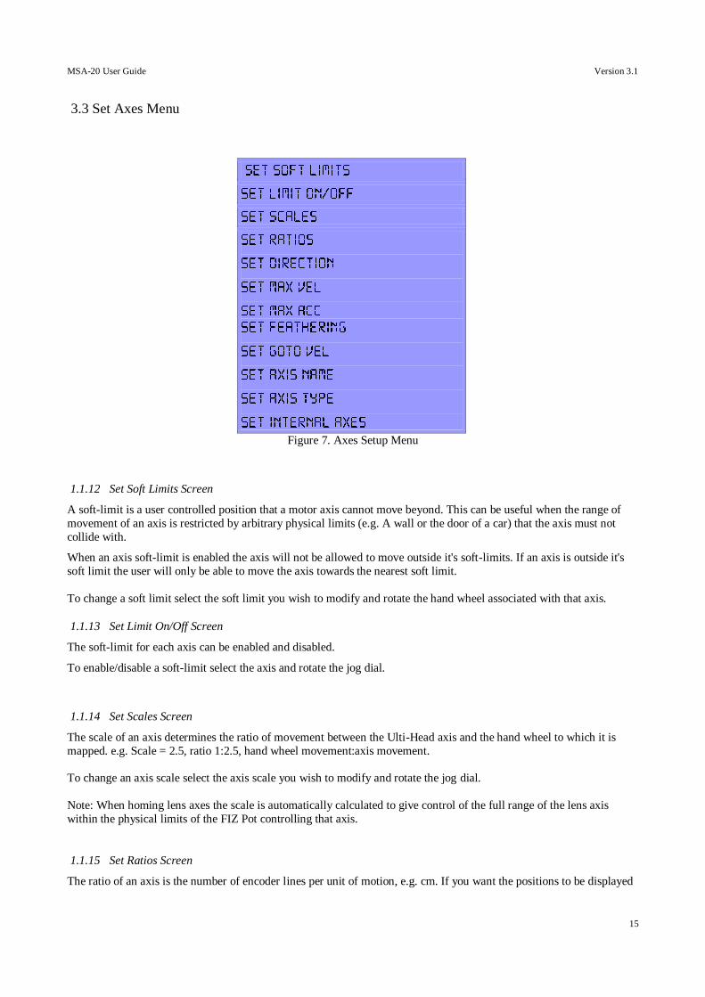
3.3 Set Axes Menu
Figure 7. Axes Setup Menu
1.1.12 Set Soft Limits Screen
A soft-limit is a user controlled position that a motor axis cannot move beyond. This can be useful when the range of
movement of an axis is restricted by arbitrary physical limits (e.g. A wall or the door of a car) that the axis must not
collide with.
When an axis soft-limit is enabled the axis will not be allowed to move outside it's soft-limits. If an axis is outside it's
soft limit the user will only be able to move the axis towards the nearest soft limit.
To change a soft limit select the soft limit you wish to modify and rotate the hand wheel associated with that axis.
1.1.13 Set Limit On/Off Screen
The soft-limit for each axis can be enabled and disabled.
To enable/disable a soft-limit select the axis and rotate the jog dial.
1.1.14 Set Scales Screen
The scale of an axis determines the ratio of movement between the Ulti-Head axis and the hand wheel to which it is
mapped. e.g. Scale = 2.5, ratio 1:2.5, hand wheel movement:axis movement.
To change an axis scale select the axis scale you wish to modify and rotate the jog dial.
Note: When homing lens axes the scale is automatically calculated to give control of the full range of the lens axis
within the physical limits of the FIZ Pot controlling that axis.
1.1.15 Set Ratios Screen
The ratio of an axis is the number of encoder lines per unit of motion, e.g. cm. If you want the positions to be displayed
MSA-20 User Guide Version 3.1
16
in real units then you must set the axis ratio to the correct scaling factor. This allows exported moved to be displayed in
real world units.
1.1.16 Set Direction Screen
The direction that the motor turns in relation to hand wheel rotation can be changed, options are:
FWD – Hand wheel rotates forward motor rotates forward.
REV – Hand wheel rotates forward motor rotates backwards.
OFF – Motor not affected by hand wheel movement.
This will also change direction in which the axis will move when homing. For Lens axes this will not take effect until
the axis has been re-homed. Once re-homed the lens axis zero position will be at the opposite end of the lens travel.
To change the hand wheel direction select the hand wheel, rotate the jog dial, and press the select button.
1.1.17 Set Axis Max Velocity Screen
The maximum axis velocity is set here. This value limits the maximum velocity command that the MSA-20 can send to
that Ulti-Head axis.
To change the axis maximum velocity select the desired axis and rotate the jog dial.
1.1.18 Set Axis Max Acceleration Screen
The maximum axis acceleration is set here. This value limits the maximum acceleration command that the MSA-20 can
send to that Ulti-Head axis.
To change the axis maximum acceleration select the desired axis and rotate the jog dial.
1.1.19 Set Axis Feathering Screen
The axis feathering controls the maximum deceleration an axis can have as it approaches a soft limit. The lower the
feathering the further away an axis is before it starts slowing down to come to a stop on it's soft limit.
To change the axis feathering select the desired axis and rotate the jog dial.
1.1.20 Set Axis Goto Velocity Screen
This controls the maximum speed an axis can move at when it is moving to the start position of a move that is to be
played back. It is set as a percentage of the normal maximum axis velocity.
To change the axis goto velocity select the axis and rotate the jog dial.
1.1.21 Set Axis Name Screen
If an axis is given a name then that name will appear in subsequent menus in place of the axis number. This is to assist
in axes selection and is also used when transferring recorded moves to the PC Move Archiver software.
To change an axis name select the desired axis and rotate the jog dial.
1.1.22 Set Axis Type Screen
An axis can have one of the following types:
MSA-20 User Guide Version 3.1
17
1). Stnd - A standard type axis (e.g. Tilt) is homed using datum limits and has relative hand wheel control.
2). Lens - A lens type axis is homed using physical limits and has absolute hand wheel control.
3). Bars – A pan bars type axis is homed using datum limits and has absolute hand wheel control.
4). Analog – An analog type axis is direct zeroed when homing and produces an analog Voltage proportional to the axis
position*.
To change an axis type select the desired axis and rotate the jog dial.
*The Analog axis type has been designed to drive a Canon Lens Controller (e.g. KJ20X8.5B KTSM). This output is
only applicable to MRMC Quad-Axis based systems on axes 5 to 8, currently as part of the SFH-30 system. Please
contact MRMC for details.
1.1.23 Set Internal Axes Screen
The MSA-20 can directly drive 2 stepper motors using the GPO outputs on the expansion connector (25-way D-Type).
These outputs are shared with the LED enable outputs that are used when Mimic handwheels are connected to the
MSA-20. These stepper motor axes are known as internal axes.
The 2 stepper motor outputs can be set to copy the movement of any of the MSA-20 external motor axes, e.g. Pan. If the
internal axis is mapped to an external motor then the GPO output will be set to drive a stepper motor. If the internal axis
is not mapped then the GPO outputs will behave as LED enable outputs.
Note: A datum limit is magnetic switch (Reed switch) on the axis that is closed when the axis reached the datum limit
position (This is the same as a datum sensor).
MSA-20 User Guide Version 3.1
18
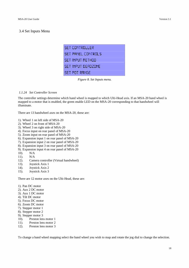
3.4 Set Inputs Menu
Figure 8. Set Inputs menu.
1.1.24 Set Controller Screen
The controller settings determine which hand wheel is mapped to which Ulti-Head axis. If an MSA-20 hand wheel is
mapped to a motor that is enabled, the green enable LED on the MSA-20 corresponding to that handwheel will
illuminate.
There are 13 handwheel axes on the MSA-20, these are:
1). Wheel 1 on left side of MSA-20
2). Wheel 2 on front of MSA-20
3). Wheel 3 on right side of MSA-20
4). Focus input on rear panel of MSA-20 5). Zoom input on rear panel of MSA-20
6). Expansion input 1 on rear panel of MSA-20
7). Expansion input 2 on rear panel of MSA-20
8). Expansion input 3 on rear panel of MSA-20
9). Expansion input 4 on rear panel of MSA-20
10). N/A
11). N/A
12). Camera controller (Virtual handwheel)
13). Joystick Axis 1
14). Joystick Axis 2
15). Joystick Axis 3
There are 12 motor axes on the Ulti-Head, these are:
1). Pan DC motor
2). Aux 2 DC motor
3). Aux 1 DC motor
4). Tilt DC motor
5). Focus DC motor
6). Zoom DC motor
7). Stepper motor 1
8). Stepper motor 2
9). Stepper motor 3 10). Preston lens motor 1
11). Preston lens motor 2
12). Preston lens motor 3
To change a hand wheel mapping select the hand wheel you wish to map and rotate the jog dial to change the selection.
MSA-20 User Guide Version 3.1
19
If an axis has already had a hand wheel mapped to it higher in the list then the new mapping will not be stored. Remove
any mapping to the desired axis and re-map as required.
1.1.25 Set Panel Controls Screen
The panel controls are the 3 columns of switches and knobs on the top of the MSA-20 that allow the user to quickly
modify the scaling and direction of an axis. These can be assigned to any axis, though they are usually assigned to hand-
wheels 1,2 and 3.
To change the axis to which a control is assigned select the axis and rotate the jog dial.
1.1.26 Set Input Method Screen
The controller style can be set to normal or speed boat.
Normal – Handwheel encoder position affects motor position
Speedboat – Hand wheel encoder position affects motor velocity (requires speedboat style controller).
To change the input method select the hand wheel, rotate the jog dial, and press the select button.
1.1.27 Set Input Deadzone Screen
The input deadzone affects axes with their input method set to speedboat. The deadzone affects the amount of input
movement before the motor axis responds to the movement. The greater the input deadzone the more input movement is required before the motor axis responds.
To change the input deadzone select the hand wheel, rotate the jog dial, and press the select button.
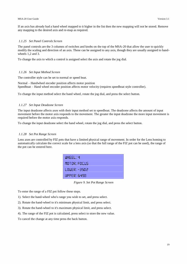
1.1.28 Set Pot Range Screen
Lens axes are controlled by FIZ pots that have a limited physical range of movement. In order for the Lens homing to
automatically calculate the correct scale for a lens axis (so that the full range of the FIZ pot can be used), the range of
the pot can be entered here.
Figure 9. Set Pot Range Screen
To enter the range of a FIZ pot follow these steps.
1). Select the hand-wheel who's range you wish to set, and press select.
2). Rotate the hand-wheel to it's minimum physical limit, and press select.
3). Rotate the hand-wheel to it's maximum physical limit, and press select.
4). The range of the FIZ pot is calculated, press select to store the new value.
To cancel the change at any time press the back button.
MSA-20 User Guide Version 3.1
20
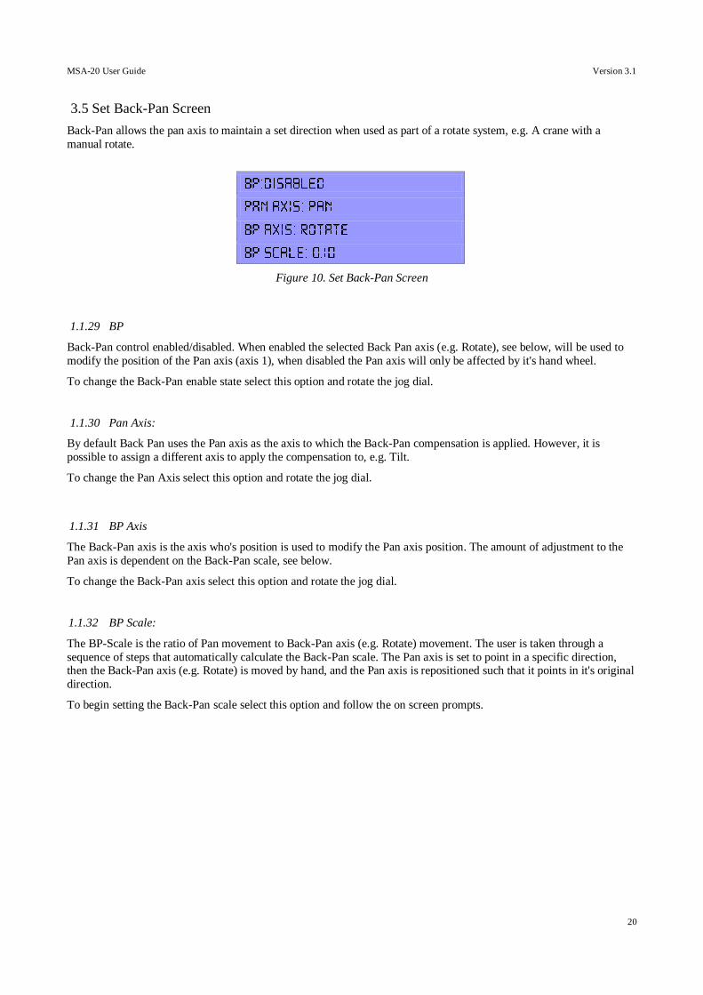
3.5 Set Back-Pan Screen
Back-Pan allows the pan axis to maintain a set direction when used as part of a rotate system, e.g. A crane with a
manual rotate.
Figure 10. Set Back-Pan Screen
1.1.29 BP
Back-Pan control enabled/disabled. When enabled the selected Back Pan axis (e.g. Rotate), see below, will be used to
modify the position of the Pan axis (axis 1), when disabled the Pan axis will only be affected by it's hand wheel.
To change the Back-Pan enable state select this option and rotate the jog dial.
1.1.30 Pan Axis:
By default Back Pan uses the Pan axis as the axis to which the Back-Pan compensation is applied. However, it is
possible to assign a different axis to apply the compensation to, e.g. Tilt.
To change the Pan Axis select this option and rotate the jog dial.
1.1.31 BP Axis
The Back-Pan axis is the axis who's position is used to modify the Pan axis position. The amount of adjustment to the
Pan axis is dependent on the Back-Pan scale, see below.
To change the Back-Pan axis select this option and rotate the jog dial.
1.1.32 BP Scale:
The BP-Scale is the ratio of Pan movement to Back-Pan axis (e.g. Rotate) movement. The user is taken through a
sequence of steps that automatically calculate the Back-Pan scale. The Pan axis is set to point in a specific direction, then the Back-Pan axis (e.g. Rotate) is moved by hand, and the Pan axis is repositioned such that it points in it's original
direction.
To begin setting the Back-Pan scale select this option and follow the on screen prompts.
MSA-20 User Guide Version 3.1
21
3.6 Serial Setup Screen
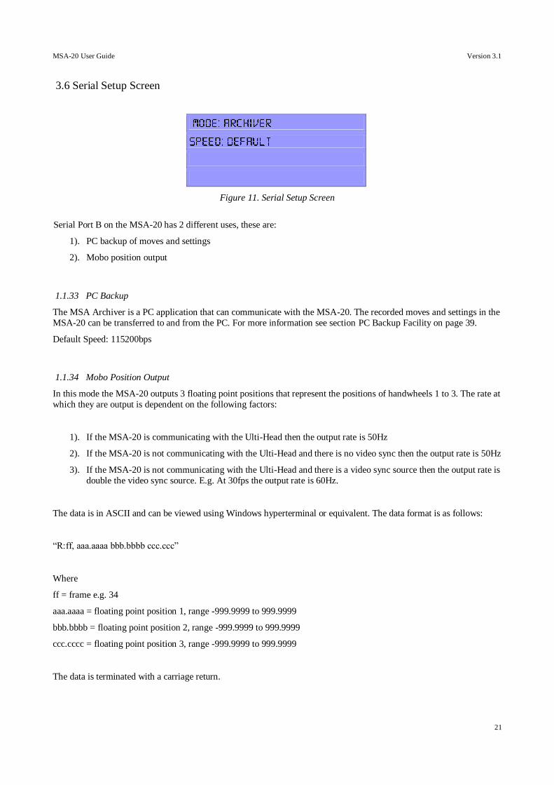
Figure 11. Serial Setup Screen
Serial Port B on the MSA-20 has 2 different uses, these are:
1). PC backup of moves and settings
2). Mobo position output
1.1.33 PC Backup
The MSA Archiver is a PC application that can communicate with the MSA-20. The recorded moves and settings in the
MSA-20 can be transferred to and from the PC. For more information see section PC Backup Facility on page 39.
Default Speed: 115200bps
1.1.34 Mobo Position Output
In this mode the MSA-20 outputs 3 floating point positions that represent the positions of handwheels 1 to 3. The rate at
which they are output is dependent on the following factors:
1). If the MSA-20 is communicating with the Ulti-Head then the output rate is 50Hz
2). If the MSA-20 is not communicating with the Ulti-Head and there is no video sync then the output rate is 50Hz
3). If the MSA-20 is not communicating with the Ulti-Head and there is a video sync source then the output rate is
double the video sync source. E.g. At 30fps the output rate is 60Hz.
The data is in ASCII and can be viewed using Windows hyperterminal or equivalent. The data format is as follows:
“R:ff, aaa.aaaa bbb.bbbb ccc.ccc”
Where
ff = frame e.g. 34
aaa.aaaa = floating point position 1, range -999.9999 to 999.9999
bbb.bbbb = floating point position 2, range -999.9999 to 999.9999
ccc.cccc = floating point position 3, range -999.9999 to 999.9999
The data is terminated with a carriage return.

MSA-20 User Guide Version 3.1
22
Default Speed: 38400bps
MSA-20 User Guide Version 3.1
23
3.7 Set Low Level Menu (Advanced Users Only)
These settings affect the DC motor control on the Ulti-Head, they have been factory set and should not normally be
changed unless instructed to by an engineer.
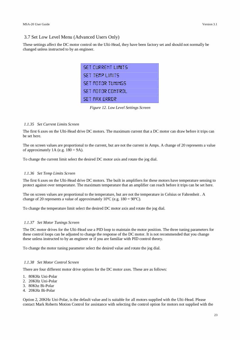
Figure 12. Low Level Settings Screen
1.1.35 Set Current Limits Screen
The first 6 axes on the Ulti-Head drive DC motors. The maximum current that a DC motor can draw before it trips can
be set here.
The on screen values are proportional to the current, but are not the current in Amps. A change of 20 represents a value
of approximately 1A (e.g. 180 = 9A).
To change the current limit select the desired DC motor axis and rotate the jog dial.
1.1.36 Set Temp Limits Screen
The first 6 axes on the Ulti-Head drive DC motors. The built in amplifiers for these motors have temperature sensing to
protect against over temperature. The maximum temperature that an amplifier can reach before it trips can be set here.
The on screen values are proportional to the temperature, but are not the temperature in Celsius or Fahrenheit . A
change of 20 represents a value of approximately 10ºC (e.g. 180 = 90ºC).
To change the temperature limit select the desired DC motor axis and rotate the jog dial.
1.1.37 Set Motor Tunings Screen
The DC motor drives for the Ulti-Head use a PID loop to maintain the motor position. The three tuning parameters for
these control loops can be adjusted to change the response of the DC motor. It is not recommended that you change these unless instructed to by an engineer or if you are familiar with PID control theory.
To change the motor tuning parameter select the desired value and rotate the jog dial.
1.1.38 Set Motor Control Screen
There are four different motor drive options for the DC motor axes. These are as follows:
1. 80KHz Uni-Polar
2. 20KHz Uni-Polar
3. 80Khz Bi-Polar
4. 20KHz Bi-Polar
Option 2, 20KHz Uni-Polar, is the default value and is suitable for all motors supplied with the Ulti-Head. Please
contact Mark Roberts Motion Control for assistance with selecting the control option for motors not supplied with the

MSA-20 User Guide Version 3.1
24
Ulti-Head.
WARNING: Selection of an incorrect drive option may damage the motor.
1.1.39 Set Max Error Screen
The maximum axis position error can be set. The maximum position error is the difference between the desired motor
position and the actual motor position beyond which the axis will trip. The larger the maximum error the less likely an
axis will trip due to position error.
Having a large maximum error prevents the user from being able to make handwheel motions that will cause an axis to
switch off. However, having the error too large can cause problems for multi-pass film effects.
MSA-20 User Guide Version 3.1
25
3.8 Home Axes Menu
The MSA-20 can home the axes of the Ulti-Head so that playback of recorded moves can be repeated frame accurately
when used with a sync source (E.g. Video sync). There are 2 types of homing for the 3 different types of axis:
1). Datum Limit homing – used for axis types Standard (Stnd) and Pan Bars (Bars)
2). Physical Limit homing – used for lens type axes
When using datum limit homing an axis will move until it finds a datum limit. Once a datum limit has been found the
axis will reverse direction and move away from the datum limit a much slower speed. When the axis detects that it has
moved off the datum limit it will stop moving and zero at that position.
When using physical limit homing the axis will move until it reaches a hard-limit (e.g. One end of travel of a lens). The
axis will store this position and then start moving in the opposite direction. When the axis reaches the hard-limit at the
opposite end of axis the axis will stop moving and store the current position. The axis will zero at this position and then
calculate the axis controller (FIZ pot) scale so that the controller can move the axis between the two hard-limits.
Note: For the correct FIZ pot scale to be calculated the number of encoder lines that the FIZ pot has must be known.
See section Set Pot Range Screen on page 19 for details.
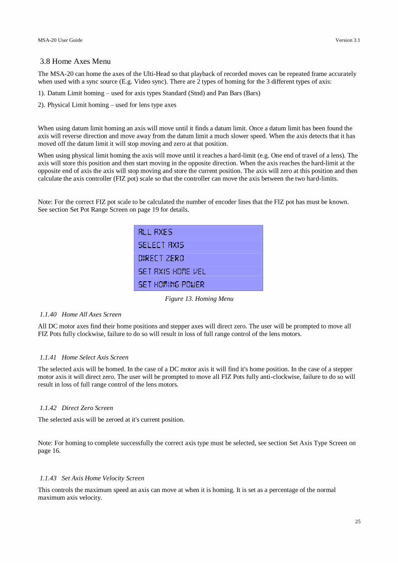
Figure 13. Homing Menu
1.1.40 Home All Axes Screen
All DC motor axes find their home positions and stepper axes will direct zero. The user will be prompted to move all
FIZ Pots fully clockwise, failure to do so will result in loss of full range control of the lens motors.
1.1.41 Home Select Axis Screen
The selected axis will be homed. In the case of a DC motor axis it will find it's home position. In the case of a stepper
motor axis it will direct zero. The user will be prompted to move all FIZ Pots fully anti-clockwise, failure to do so will
result in loss of full range control of the lens motors.
1.1.42 Direct Zero Screen
The selected axis will be zeroed at it's current position.
Note: For homing to complete successfully the correct axis type must be selected, see section Set Axis Type Screen on
page 16.
1.1.43 Set Axis Home Velocity Screen
This controls the maximum speed an axis can move at when it is homing. It is set as a percentage of the normal
maximum axis velocity.

MSA-20 User Guide Version 3.1
26
To change the axis homing velocity select the axis and rotate the jog dial.
1.1.44 Set Homing Power Screen
This allows the user to set the maximum amount effort that a motor can apply when homing an axis. This is used when
homing lens axes to limit the force applied when a lens motor reaches a hard limit (i.e. at each end of travel of the lens).
If this value is too high the lens motor gear will jump out of mesh with the lens and homing will fail.
MSA-20 User Guide Version 3.1
27
3.9 Record and Playback Menu
The MSA-20 can record over 174 axis-minutes of move data. Should more space be required the data can be transferred to a PC to free up space on the MSA-20. Data is transferred using the MSA Archiver PC software.
The MSA-20 record and playback facility includes:
1). Selection of which axes to record
2). Playback of recorded moves
3). Re-recording/adding axes to previously recorded moves (Modify)
4). Deletion of individual moves
5). Deletion of all recorded moves
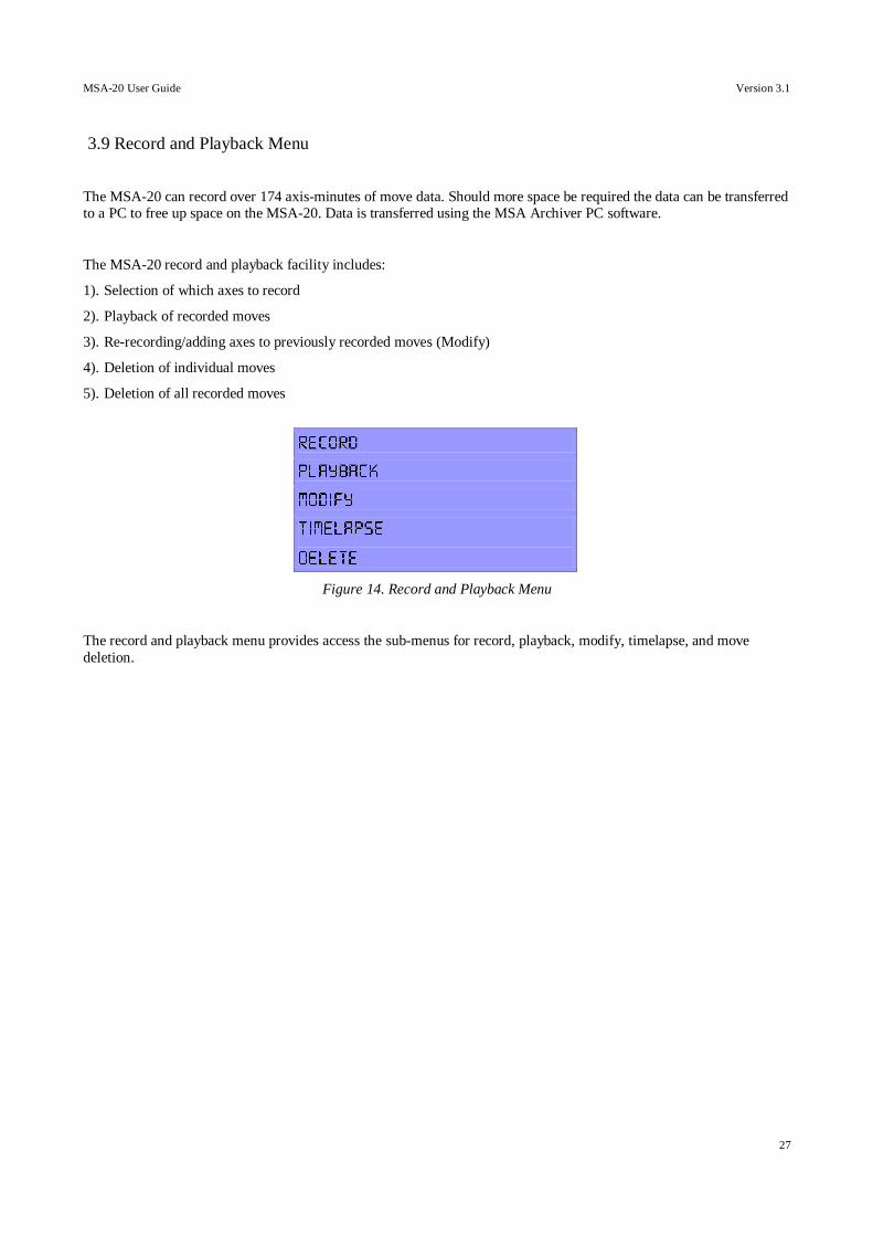
Figure 14. Record and Playback Menu
The record and playback menu provides access the sub-menus for record, playback, modify, timelapse, and move
deletion.
MSA-20 User Guide Version 3.1
28
3.10 Record Menu
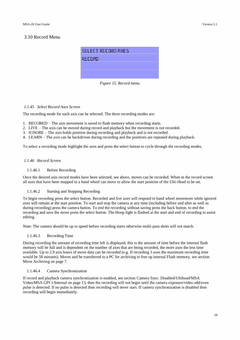
Figure 15. Record menu.
1.1.45 Select Record Axes Screen
The recording mode for each axis can be selected. The three recording modes are:
1. RECORED – The axis movement is saved to flash memory when recording starts.
2. LIVE – The axis can be moved during record and playback but the movement is not recorded.
3. IGNORE – The axis holds position during recording and playback and is not recorded.
4. LEARN – The axis can be backdriven during recording and the positions are repeated during playback.
To select a recording mode highlight the axes and press the select button to cycle through the recording modes.
1.1.46 Record Screen
1.1.46.1 Before Recording
Once the desired axis record modes have been selected, see above, moves can be recorded. When in the record screen
all axes that have been mapped to a hand wheel can move to allow the start position of the Ulti-Head to be set.
1.1.46.2 Starting and Stopping Recording
To begin recording press the select button. Recorded and live axes will respond to hand wheel movement while ignored
axes will remain at the start position. To start and stop the camera at any time (including before and after as well as
during recording) press the camera button. To end the recording without saving press the back button, to end the
recording and save the move press the select button. The bloop light is flashed at the start and end of recording to assist editing.
Note: The camera should be up to speed before recording starts otherwise multi-pass shots will not match.
1.1.46.3 Recording Time
During recording the amount of recording time left is displayed, this is the amount of time before the internal flash
memory will be full and is dependent on the number of axes that are being recorded, the more axes the less time
available. Up to 2.9 axis hours of move data can be recorded (e.g. If recording 3 axes the maximum recording time
would be 58 minutes). Moves and be transferred to a PC for archiving to free up internal Flash memory, see section
Move Archiving on page 7.
1.1.46.4 Camera Synchronization
If record and playback camera synchronization is enabled, see section Camera Sync: Disabled/Ultihead/MSA Video/MSA GPI 1/Internal on page 13, then the recording will not begin until the camera exposure/video odd/even
pulse is detected. If no pulse is detected then recording will never start. If camera synchronization is disabled then
recording will begin immediately.
MSA-20 User Guide Version 3.1
29
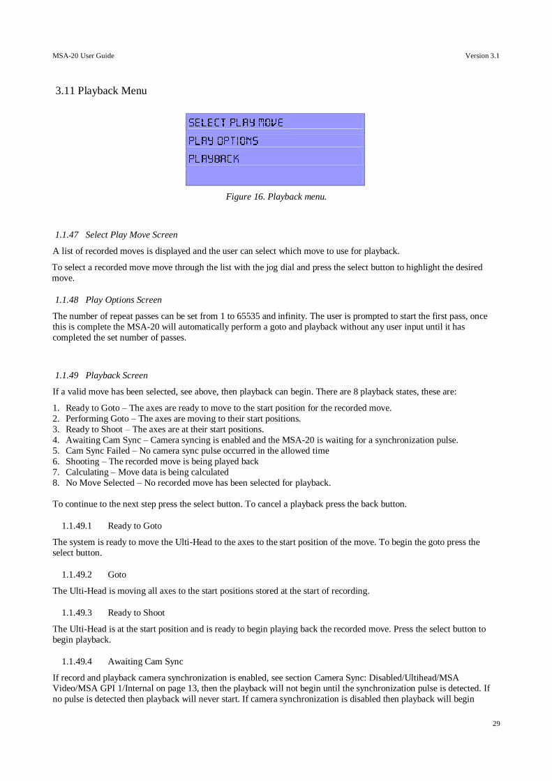
3.11 Playback Menu
Figure 16. Playback menu.
1.1.47 Select Play Move Screen
A list of recorded moves is displayed and the user can select which move to use for playback.
To select a recorded move move through the list with the jog dial and press the select button to highlight the desired
move.
1.1.48 Play Options Screen
The number of repeat passes can be set from 1 to 65535 and infinity. The user is prompted to start the first pass, once
this is complete the MSA-20 will automatically perform a goto and playback without any user input until it has
completed the set number of passes.
1.1.49 Playback Screen
If a valid move has been selected, see above, then playback can begin. There are 8 playback states, these are:
1. Ready to Goto – The axes are ready to move to the start position for the recorded move.
2. Performing Goto – The axes are moving to their start positions.
3. Ready to Shoot – The axes are at their start positions.
4. Awaiting Cam Sync – Camera syncing is enabled and the MSA-20 is waiting for a synchronization pulse.
5. Cam Sync Failed – No camera sync pulse occurred in the allowed time
6. Shooting – The recorded move is being played back
7. Calculating – Move data is being calculated
8. No Move Selected – No recorded move has been selected for playback.
To continue to the next step press the select button. To cancel a playback press the back button.
1.1.49.1 Ready to Goto
The system is ready to move the Ulti-Head to the axes to the start position of the move. To begin the goto press the
select button.
1.1.49.2 Goto
The Ulti-Head is moving all axes to the start positions stored at the start of recording.
1.1.49.3 Ready to Shoot
The Ulti-Head is at the start position and is ready to begin playing back the recorded move. Press the select button to
begin playback.
1.1.49.4 Awaiting Cam Sync
If record and playback camera synchronization is enabled, see section Camera Sync: Disabled/Ultihead/MSA Video/MSA GPI 1/Internal on page 13, then the playback will not begin until the synchronization pulse is detected. If
no pulse is detected then playback will never start. If camera synchronization is disabled then playback will begin
MSA-20 User Guide Version 3.1
30
immediately.
Note: If this message appears then multi-pass shots will not match as the camera should already be up to speed at this
point.
1.1.49.5 Cam Sync Failed
No sync pulse was detected within the time limit allowed and so the move could not start. The sync timeout can be
changed in the camera setup menu, see section Camera Sync Timeout on page 13.
1.1.49.6 Shooting
The MSA-20 is playing back the selected recorded move. Recorded axes will follow the recorded movement, ignored
axes will remain at the goto position, and live axes can be controlled by the hand wheel to which they are mapped. The
amount of time left before playback ends is displayed, when the move ends the playback state changes to read to goto.
The bloop light is flashed at the start and end of playback to assist editing.
1.1.49.7 No Move Selected
If no move was selected before playback then a message is displayed indicating this. If a new move has just been
recorded this is automatically selected as the playback move.
MSA-20 User Guide Version 3.1
31
3.12 Modify Screen
Modify allows new axes to be added to a previous recording and/or over-writing of recorded axes within a move. The
user selects which move they would like to use for playback, and which axes are to be recorded/re-recorded. The user then plays back the previous recording while recording the playback axes and the axes under hand wheel control to a
new move.
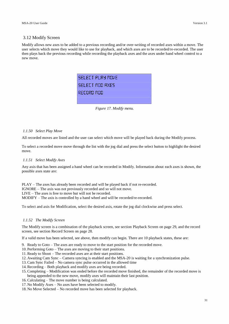
Figure 17. Modify menu.
1.1.50 Select Play Move
All recorded moves are listed and the user can select which move will be played back during the Modify process.
To select a recorded move move through the list with the jog dial and press the select button to highlight the desired
move.
1.1.51 Select Modify Axes
Any axis that has been assigned a hand wheel can be recorded in Modify. Information about each axes is shown, the
possible axes state are:
PLAY – The axes has already been recorded and will be played back if not re-recorded.
IGNORE – The axis was not previously recorded and so will not move.
LIVE – The axes is free to move but will not be recorded.
MODIFY – The axis is controlled by a hand wheel and will be recorded/re-recorded.
To select and axis for Modification, select the desired axis, rotate the jog dial clockwise and press select.
1.1.52 The Modify Screen
The Modify screen is a combination of the playback screen, see section Playback Screen on page 29, and the record
screen, see section Record Screen on page 28.
If a valid move has been selected, see above, then modify can begin. There are 10 playback states, these are:
9. Ready to Goto – The axes are ready to move to the start position for the recorded move.
10. Performing Goto – The axes are moving to their start positions.
11. Ready to Shoot – The recorded axes are at their start positions.
12. Awaiting Cam Sync – Camera syncing is enabled and the MSA-20 is waiting for a synchronization pulse. 13. Cam Sync Failed – No camera sync pulse occurred in the allowed time
14. Recording – Both playback and modify axes are being recorded.
15. Completing – Modification was ended before the recorded move finished, the remainder of the recorded move is
being appended to the new move, modify axes will maintain their last position.
16. Calculating – The move number is being calculated.
17. No Modify Axes – No axes have been selected to modify.
18. No Move Selected – No recorded move has been selected for playback.

MSA-20 User Guide Version 3.1
32
To continue on to the next step press the select button. To cancel Modify without saving the move press the back
button.
MSA-20 User Guide Version 3.1
33
3.13 Timelapse Screen
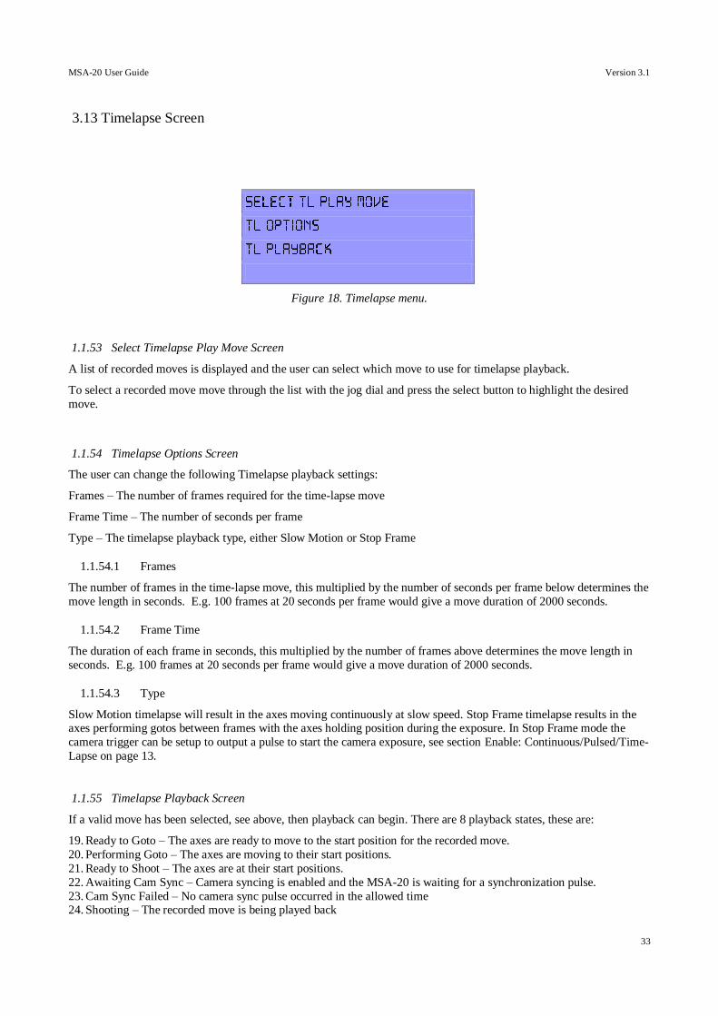
Figure 18. Timelapse menu.
1.1.53 Select Timelapse Play Move Screen
A list of recorded moves is displayed and the user can select which move to use for timelapse playback.
To select a recorded move move through the list with the jog dial and press the select button to highlight the desired
move.
1.1.54 Timelapse Options Screen
The user can change the following Timelapse playback settings:
Frames – The number of frames required for the time-lapse move
Frame Time – The number of seconds per frame
Type – The timelapse playback type, either Slow Motion or Stop Frame
1.1.54.1 Frames
The number of frames in the time-lapse move, this multiplied by the number of seconds per frame below determines the
move length in seconds. E.g. 100 frames at 20 seconds per frame would give a move duration of 2000 seconds.
1.1.54.2 Frame Time
The duration of each frame in seconds, this multiplied by the number of frames above determines the move length in
seconds. E.g. 100 frames at 20 seconds per frame would give a move duration of 2000 seconds.
1.1.54.3 Type
Slow Motion timelapse will result in the axes moving continuously at slow speed. Stop Frame timelapse results in the axes performing gotos between frames with the axes holding position during the exposure. In Stop Frame mode the
camera trigger can be setup to output a pulse to start the camera exposure, see section Enable: Continuous/Pulsed/Time-
Lapse on page 13.
1.1.55 Timelapse Playback Screen
If a valid move has been selected, see above, then playback can begin. There are 8 playback states, these are:
19. Ready to Goto – The axes are ready to move to the start position for the recorded move.
20. Performing Goto – The axes are moving to their start positions.
21. Ready to Shoot – The axes are at their start positions.
22. Awaiting Cam Sync – Camera syncing is enabled and the MSA-20 is waiting for a synchronization pulse.
23. Cam Sync Failed – No camera sync pulse occurred in the allowed time 24. Shooting – The recorded move is being played back

MSA-20 User Guide Version 3.1
34
25. Calculating – Move data is being calculated
26. No Move Selected – No recorded move has been selected for timelapse playback.
To continue to the next step press the select button. To cancel a timelapse playback press the back button.
MSA-20 User Guide Version 3.1
35
3.14 Delete Screen
Modify allows new axes to be added to a previous recording and/or over-writing of recorded axes within a move. The
user selects which move they would like to use for playback, and which axes are to be recorded/re-recorded. The user then plays back the previous recording while recording the playback axes and the axes under hand wheel control to a
new move.
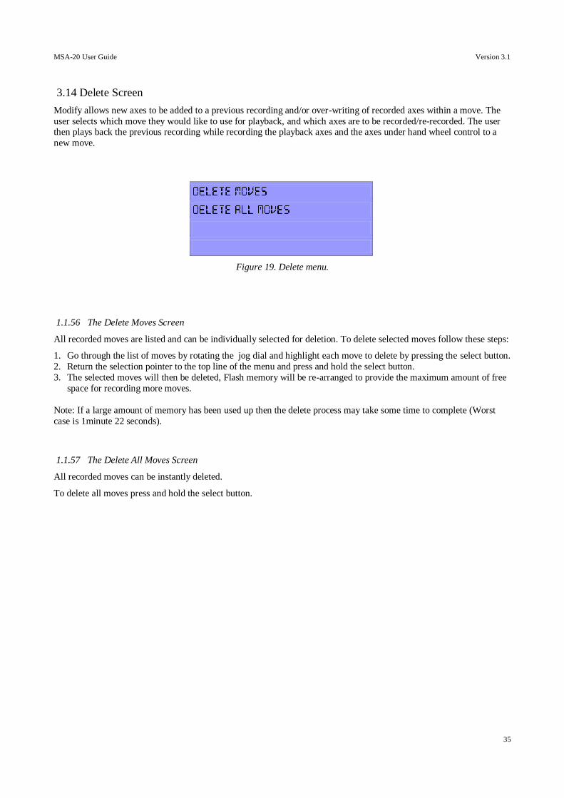
Figure 19. Delete menu.
1.1.56 The Delete Moves Screen
All recorded moves are listed and can be individually selected for deletion. To delete selected moves follow these steps:
1. Go through the list of moves by rotating the jog dial and highlight each move to delete by pressing the select button.
2. Return the selection pointer to the top line of the menu and press and hold the select button.
3. The selected moves will then be deleted, Flash memory will be re-arranged to provide the maximum amount of free
space for recording more moves.
Note: If a large amount of memory has been used up then the delete process may take some time to complete (Worst
case is 1minute 22 seconds).
1.1.57 The Delete All Moves Screen
All recorded moves can be instantly deleted.
To delete all moves press and hold the select button.
MSA-20 User Guide Version 3.1
36
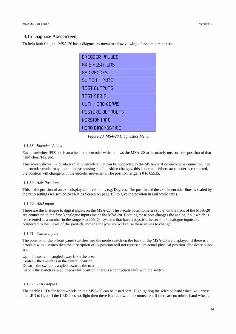
3.15 Diagnose Axes Screen
To help fault find, the MSA-20 has a diagnostics menu to allow viewing of system parameters.
Figure 20. MSA-20 Diagnostics Menu
1.1.58 Encoder Values
Each handwheel/FIZ pot is attached to an encoder which allows the MSA-20 to accurately measure the position of that
handwheel/FIZ pot.
This screen shows the position of all 9 encoders that can be connected to the MSA-20. If no encoder is connected then
the encoder reader may pick up noise causing small position changes, this is normal. Where an encoder is connected,
the position will change with the encoder movement. The position range is 0 to 65535.
1.1.59 Axis Positions
This is the position of an axis displayed in real units, e.g. Degrees. The position of the axis in encoder lines is scaled by the ratio setting (see section Set Ratios Screen on page 15) to give the position in real world units.
1.1.60 A2D inputs
These are the analogue to digital inputs on the MSA-20. The 3 scale potentiometers (pots) on the front of the MSA-20
are connected to the first 3 analogue inputs inside the MSA-20. Rotating these pots changes the analog input which is
represented as a number in the range 0 to 255. On systems that have a joystick the second 3 analogue inputs are
connected to the 3 axes of the joystick, moving the joystick will cause these values to change.
1.1.61 Switch Inputs
The position of the 6 front panel switches and the mode switch on the back of the MSA-20 are displayed, if there is a
problem with a switch then the description of its position will not represent its actual physical position. The descriptions
are:
Up – the switch is angled away from the user.
Centre – the switch is in the central position. Down – the switch is angled towards the user.
Error – the switch is in an impossible position, there is a connection fault with the switch.
1.1.62 Test Outputs
The enable LEDs for hand wheels on the MSA-20 can be tested here. Highlighting the selected hand wheel will cause
the LED to light. If the LED does not light then there is a fault with its connection. If there are no mimic hand wheels
MSA-20 User Guide Version 3.1
37
connected on the expansion connector then you will not see any enable LED's light up for these additional handwheels.
1.1.63 Test Serial
The serial ports and the MSA-20 can bet tested to ensure correct communication. Alphabetic characters are sent out on
each port and any received characters are displayed. Loop back testing is the best method of testing, this is where the
transmit pin is connected to the receive pin, so all sent characters are echoed back to the display. If the Ulti-Head is
connected then this test will fail.
1.1.64 Ulti-Head Comms
This display the following information:
Uptime – The amount of time the MSA-20 has been power up.
Received – The number of packets of data that have been successfully received from the Ulti-Head.
Failed – The number of packets that were corrupted.
1.1.65 Restore Defaults
All settings are restored to factory defaults and all recorded moves are erased. The user is prompted to confirm the
restore, once this has been done it cannot be undone.
1.1.66 Version Information
This displays the software and hardware version information for the MSA-20 and Ulti-Head. If the Ulti-Head is
disconnected or there is a problem the Ulti-Head version information will display “ERROR”.
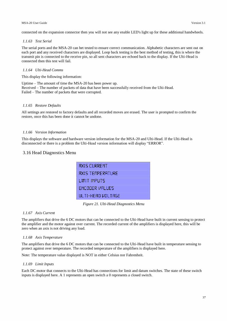
3.16 Head Diagnostics Menu
Figure 21. Ulti-Head Diagnostics Menu
1.1.67 Axis Current
The amplifiers that drive the 6 DC motors that can be connected to the Ulti-Head have built in current sensing to protect
the amplifier and the motor against over current. The recorded current of the amplifiers is displayed here, this will be
zero when an axis is not driving any load.
1.1.68 Axis Temperature
The amplifiers that drive the 6 DC motors that can be connected to the Ulti-Head have built in temperature sensing to protect against over temperature. The recorded temperature of the amplifiers is displayed here.
Note: The temperature value displayed is NOT in either Celsius nor Fahrenheit.
1.1.69 Limit Inputs
Each DC motor that connects to the Ulti-Head has connections for limit and datum switches. The state of these switch
inputs is displayed here. A 1 represents an open switch a 0 represents a closed switch.

MSA-20 User Guide Version 3.1
38
1.1.70 Encoder values
The position of the 6 possible DC motor encoders is displayed. If no encoder is connected then the encoder reader may
pick up noise causing small position changes, this is normal. Where an encoder is connected the position will change
with the encoder movement. The position range is 0 to 65535.
1.1.71 Ulti-Head Voltage
The Voltage that is powering the Ulti-Head. This is useful when running the head from batteries.
Note: If the Ulti-Head Voltage drops below 12V the DC motor outputs will not work, and below 7V the head will not
function at all.
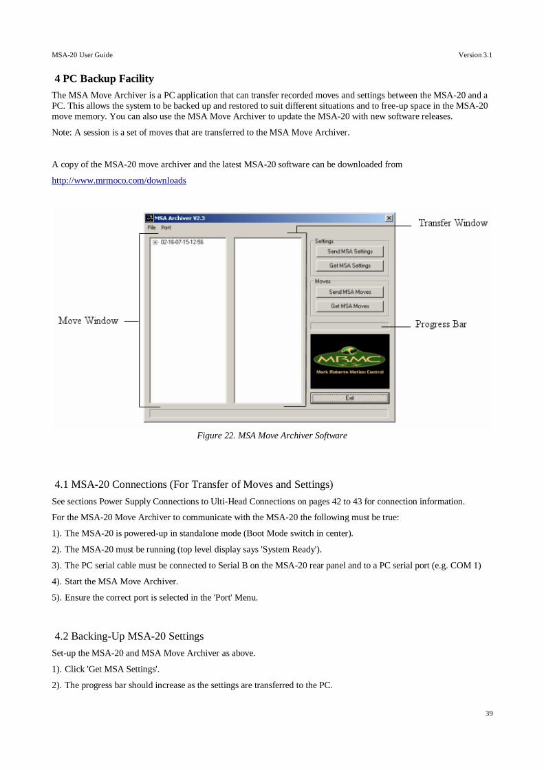
MSA-20 User Guide Version 3.1
39
4 PC Backup Facility
The MSA Move Archiver is a PC application that can transfer recorded moves and settings between the MSA-20 and a
PC. This allows the system to be backed up and restored to suit different situations and to free-up space in the MSA-20
move memory. You can also use the MSA Move Archiver to update the MSA-20 with new software releases.
Note: A session is a set of moves that are transferred to the MSA Move Archiver.
A copy of the MSA-20 move archiver and the latest MSA-20 software can be downloaded from
http://www.mrmoco.com/downloads
4.1 MSA-20 Connections (For Transfer of Moves and Settings)
See sections Power Supply Connections to Ulti-Head Connections on pages 42 to 43 for connection information.
For the MSA-20 Move Archiver to communicate with the MSA-20 the following must be true:
1). The MSA-20 is powered-up in standalone mode (Boot Mode switch in center).
2). The MSA-20 must be running (top level display says 'System Ready').
3). The PC serial cable must be connected to Serial B on the MSA-20 rear panel and to a PC serial port (e.g. COM 1)
4). Start the MSA Move Archiver.
5). Ensure the correct port is selected in the 'Port' Menu.
4.2 Backing-Up MSA-20 Settings
Set-up the MSA-20 and MSA Move Archiver as above.
1). Click 'Get MSA Settings'.
2). The progress bar should increase as the settings are transferred to the PC.
Figure 22. MSA Move Archiver Software
MSA-20 User Guide Version 3.1
40
3). Once all the settings have been received the user is prompted to save the settings to a file, e.g. HarryPotter.msa.
4.3 Restoring MSA-20 Settings from a Backup
Set-up the MSA-20 and MSA Move Archiver as in section MSA-20 Connections (For Transfer of Moves and Settings)
on page 39 above.
1). Click 'Send MSA Settings'.
2). The user is prompted to select a settings file from which the settings in the MSA-20 will be restored, e.g.
Spiderman3.msa.
3). The progress bar should increase as the settings are transferred to the MSA-20.
4). Once all the settings have been transferred a message will appear to indicate the transfer has completed.
4.4 Backing-Up MSA-20 Moves
Set-up the MSA-20 and MSA Move Archiver as in section MSA-20 Connections (For Transfer of Moves and Settings)
on page 39.
5). Click 'Get MSA Moves'.
6). The progress bar should increase as the moves are transferred to the PC.
7). Once all the moves' have been received the new session is shown in the 'Transfer Window' and the user is prompted
save them to a set of move files in a session directory, e.g. C:/MSA/02-16-07-15-12-56/. The directory is a date and
time stamp generated by the MSA Move Archiver and each move file name is the unique move number. DO NOT
EDIT THE FILE NAMES as this will affect transfer back to the MSA-20.
8). If the new session is saved it will appear in the 'Move Window'.
4.5 Restoring MSA-20 Moves from a Backup
Set-up the MSA-20 and MSA Move Archiver as in section MSA-20 Connections (For Transfer of Moves and Settings)
on page 39.
1). The 'Move Window' displays a list of all the MSA sessions that have been stored in the PC. Select the session you
wish to transfer to the MSA-20.
2). Click 'Send MSA Moves'.
3). The user is prompted to confirm they wish to send moves to the MSA-20 as this will erase any existing moves in the
MSA-20. Click 'OK' if you wish to overwrite the existing moves in the MSA-20.
4). The progress bar should increase as the moves are transferred to the MSA-20.
5). Once all the moves have been transferred a message will appear to indicate the transfer has completed.
WARNING: TRANSFERING MOVES TO THE MSA-20 WILL ERASE ANY MOVES ALREADY STORED
IN THE MSA-20.
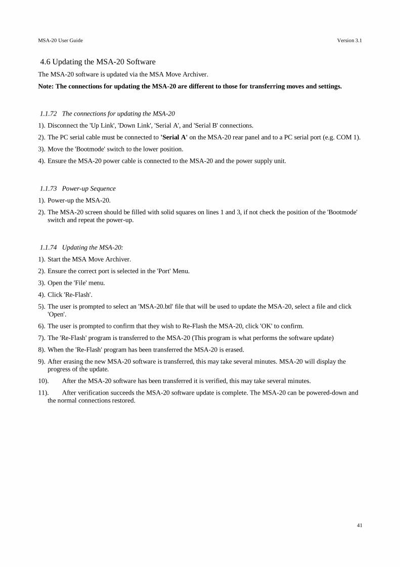
MSA-20 User Guide Version 3.1
41
4.6 Updating the MSA-20 Software
The MSA-20 software is updated via the MSA Move Archiver.
Note: The connections for updating the MSA-20 are different to those for transferring moves and settings.
1.1.72 The connections for updating the MSA-20
1). Disconnect the 'Up Link', 'Down Link', 'Serial A', and 'Serial B' connections.
2). The PC serial cable must be connected to 'Serial A' on the MSA-20 rear panel and to a PC serial port (e.g. COM 1).
3). Move the 'Bootmode' switch to the lower position.
4). Ensure the MSA-20 power cable is connected to the MSA-20 and the power supply unit.
1.1.73 Power-up Sequence
1). Power-up the MSA-20.
2). The MSA-20 screen should be filled with solid squares on lines 1 and 3, if not check the position of the 'Bootmode'
switch and repeat the power-up.
1.1.74 Updating the MSA-20:
1). Start the MSA Move Archiver.
2). Ensure the correct port is selected in the 'Port' Menu.
3). Open the 'File' menu.
4). Click 'Re-Flash'.
5). The user is prompted to select an 'MSA-20.btl' file that will be used to update the MSA-20, select a file and click
'Open'.
6). The user is prompted to confirm that they wish to Re-Flash the MSA-20, click 'OK' to confirm.
7). The 'Re-Flash' program is transferred to the MSA-20 (This program is what performs the software update)
8). When the 'Re-Flash' program has been transferred the MSA-20 is erased.
9). After erasing the new MSA-20 software is transferred, this may take several minutes. MSA-20 will display the progress of the update.
10). After the MSA-20 software has been transferred it is verified, this may take several minutes.
11). After verification succeeds the MSA-20 software update is complete. The MSA-20 can be powered-down and
the normal connections restored.
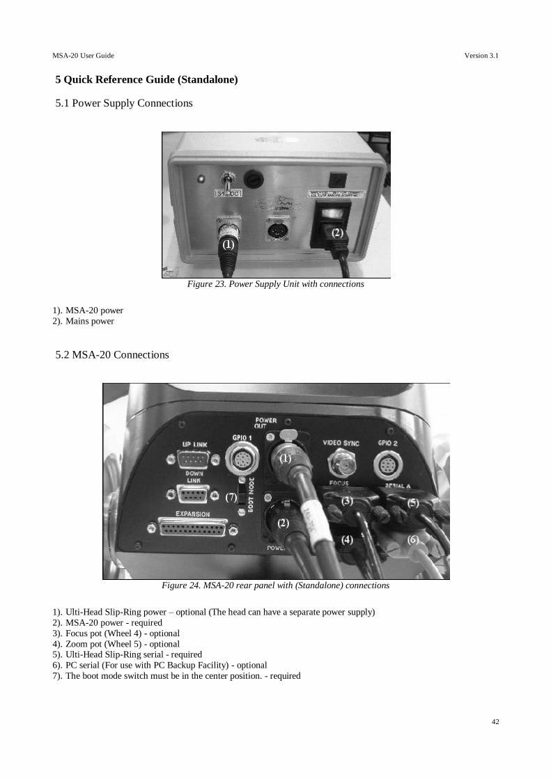
MSA-20 User Guide Version 3.1
42
5 Quick Reference Guide (Standalone)
5.1 Power Supply Connections
1). MSA-20 power
2). Mains power
5.2 MSA-20 Connections
1). Ulti-Head Slip-Ring power – optional (The head can have a separate power supply)
2). MSA-20 power - required
3). Focus pot (Wheel 4) - optional
4). Zoom pot (Wheel 5) - optional 5). Ulti-Head Slip-Ring serial - required
6). PC serial (For use with PC Backup Facility) - optional
7). The boot mode switch must be in the center position. - required
Figure 24. MSA-20 rear panel with (Standalone) connections
Figure 23. Power Supply Unit with connections
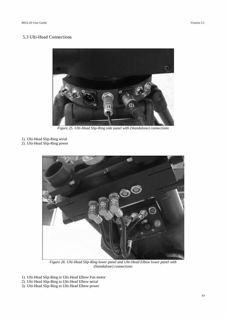
MSA-20 User Guide Version 3.1
43
5.3 Ulti-Head Connections
1). Ulti-Head Slip-Ring serial 2). Ulti-Head Slip-Ring power
1). Ulti-Head Slip-Ring to Ulti-Head Elbow Pan motor
2). Ulti-Head Slip-Ring to Ulti-Head Elbow serial
3). Ulti-Head Slip-Ring to Ulti-Head Elbow power
Figure 25. Ulti-Head Slip-Ring side panel with (Standalone) connections
Figure 26. Ulti-Head Slip-Ring lower panel and Ulti-Head Elbow lower panel with
(Standalone) connections
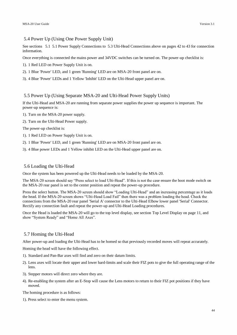
MSA-20 User Guide Version 3.1
44
5.4 Power Up (Using One Power Supply Unit)
See sections 5.1 5.1 Power Supply Connections to 5.3 Ulti-Head Connections above on pages 42 to 43 for connection
information.
Once everything is connected the mains power and 34VDC switches can be turned on. The power-up checklist is:
1). 1 Red LED on Power Supply Unit is on.
2). 1 Blue 'Power' LED, and 1 green 'Running' LED are on MSA-20 front panel are on.
3). 4 Blue 'Power' LEDs and 1 Yellow 'Inhibit' LED on the Ulti-Head upper panel are on.
5.5 Power Up (Using Separate MSA-20 and Ulti-Head Power Supply Units)
If the Ulti-Head and MSA-20 are running from separate power supplies the power up sequence is important. The power-up sequence is:
1). Turn on the MSA-20 power supply.
2). Turn on the Ulti-Head Power supply.
The power-up checklist is:
1). 1 Red LED on Power Supply Unit is on.
2). 1 Blue 'Power' LED, and 1 green 'Running' LED are on MSA-20 front panel are on.
3). 4 Blue power LEDs and 1 Yellow inhibit LED on the Ulti-Head upper panel are on.
5.6 Loading the Ulti-Head
Once the system has been powered up the Ulti-Head needs to be loaded by the MSA-20.
The MSA-20 screen should say “Press select to load Ulti-Head”. If this is not the case ensure the boot mode switch on
the MSA-20 rear panel is set to the center position and repeat the power-up procedure.
Press the select button. The MSA-20 screen should show “Loading Ulti-Head” and an increasing percentage as it loads
the head. If the MSA-20 screen shows “Ulti-Head Load Fail” then there was a problem loading the head. Check the
connections from the MSA-20 rear panel 'Serial A' connector to the Ulti-Head Elbow lower panel 'Serial' Connector.
Rectify any connection fault and repeat the power-up and Ulti-Head Loading procedures.
Once the Head is loaded the MSA-20 will go to the top level display, see section Top Level Display on page 11, and
show “System Ready” and “Home All Axes”.
5.7 Homing the Ulti-Head
After power-up and loading the Ulti-Head has to be homed so that previously recorded moves will repeat accurately.
Homing the head will have the following effect.
1). Standard and Pan-Bar axes will find and zero on their datum limits.
2). Lens axes will locate their upper and lower hard-limits and scale their FIZ pots to give the full operating range of the lens.
3). Stepper motors will direct zero where they are.
4). Re-enabling the system after an E-Stop will cause the Lens motors to return to their FIZ pot positions if they have
moved.
The homing procedure is as follows:
1). Press select to enter the menu system.
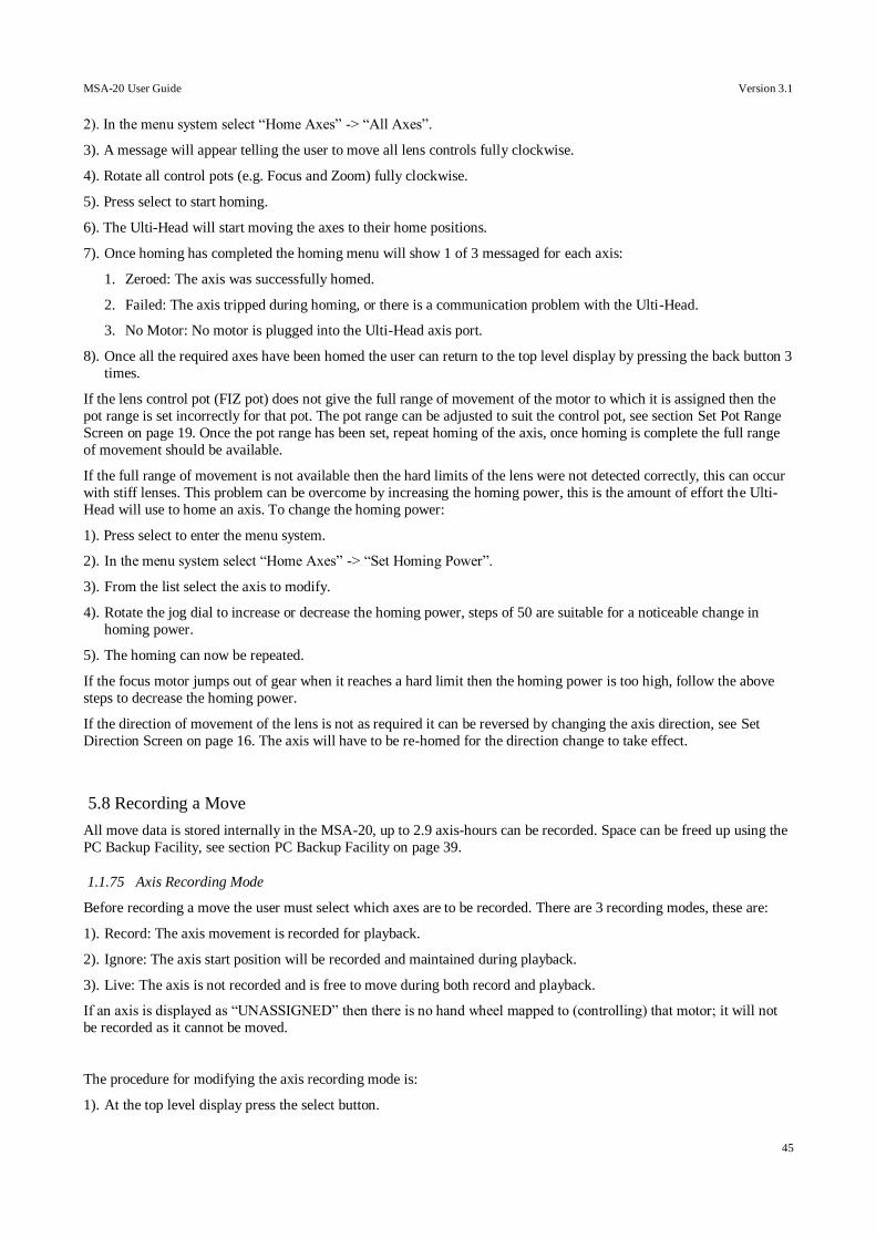
MSA-20 User Guide Version 3.1
45
2). In the menu system select “Home Axes” -> “All Axes”.
3). A message will appear telling the user to move all lens controls fully clockwise.
4). Rotate all control pots (e.g. Focus and Zoom) fully clockwise.
5). Press select to start homing.
6). The Ulti-Head will start moving the axes to their home positions.
7). Once homing has completed the homing menu will show 1 of 3 messaged for each axis:
1. Zeroed: The axis was successfully homed.
2. Failed: The axis tripped during homing, or there is a communication problem with the Ulti-Head.
3. No Motor: No motor is plugged into the Ulti-Head axis port.
8). Once all the required axes have been homed the user can return to the top level display by pressing the back button 3
times.
If the lens control pot (FIZ pot) does not give the full range of movement of the motor to which it is assigned then the
pot range is set incorrectly for that pot. The pot range can be adjusted to suit the control pot, see section Set Pot Range
Screen on page 19. Once the pot range has been set, repeat homing of the axis, once homing is complete the full range
of movement should be available.
If the full range of movement is not available then the hard limits of the lens were not detected correctly, this can occur
with stiff lenses. This problem can be overcome by increasing the homing power, this is the amount of effort the Ulti-
Head will use to home an axis. To change the homing power:
1). Press select to enter the menu system.
2). In the menu system select “Home Axes” -> “Set Homing Power”.
3). From the list select the axis to modify.
4). Rotate the jog dial to increase or decrease the homing power, steps of 50 are suitable for a noticeable change in
homing power.
5). The homing can now be repeated.
If the focus motor jumps out of gear when it reaches a hard limit then the homing power is too high, follow the above
steps to decrease the homing power.
If the direction of movement of the lens is not as required it can be reversed by changing the axis direction, see Set
Direction Screen on page 16. The axis will have to be re-homed for the direction change to take effect.
5.8 Recording a Move
All move data is stored internally in the MSA-20, up to 2.9 axis-hours can be recorded. Space can be freed up using the
PC Backup Facility, see section PC Backup Facility on page 39.
1.1.75 Axis Recording Mode
Before recording a move the user must select which axes are to be recorded. There are 3 recording modes, these are:
1). Record: The axis movement is recorded for playback.
2). Ignore: The axis start position will be recorded and maintained during playback.
3). Live: The axis is not recorded and is free to move during both record and playback.
If an axis is displayed as “UNASSIGNED” then there is no hand wheel mapped to (controlling) that motor; it will not
be recorded as it cannot be moved.
The procedure for modifying the axis recording mode is:
1). At the top level display press the select button.
MSA-20 User Guide Version 3.1
46
2). Select “Rec-Play Axes” -> Record -> ”Select Rec Axes”
3). Set the axes recording mode as desired.
4). Press the back button to return to the Record menu.
1.1.76 Recording
In the Rec-Play menu select “Record”, the Recording screen is shown.
Figure 27. Example Recording screen.
If no axes were selected for recording then the screen will display “NO AXES SELECTED”, return to the “Select Rec
Axes” menu and set at least one axis recording mode to “Rec”.
If 1 or more axes were set to record then recording can begin. The procedure for recording is:
1). Move all axes to their desired start positions:
2). Press the select button to begin recording.
3). If recording is set to synchronize to a sync source then the MSA-20 will wait for a sync pulse from the selected sync
source (e.g. MSA video), see section Set Camera Screen on page 12 or section Setting Up Synchronization on page
50. If synchronization is disabled then recording will begin immediately.
4). The axes selected for recording will have their positions stored for playback and the “Time Left” indicator will decrease.
5). To end the recording press the select button. If the back button is pressed the user is returned to the “Rec-Play Axes”
menu and the recording is lost.
6). A new move number is generated for recording another move.
If a bloop light is connected to either the MSA-20 or the Ulti-Head this will flash at the start and end of each move.
If a camera is being controlled by the MSA-20 then this can be started or stopped at any time by pressing the “Camera”
button on the MSA-20 front panel.
5.9 Playing Back a Recorded Move
The MSA-20 can playback recorded moves of up to 2.9 axes-hours in length.
1.1.77 Selecting a Move to Playback
Before playback can begin a previously recorded move must be selected.
1). In the top level display press the select button.
2). Select “Rec-Play Axes” -> Playback -> “Select Play Move”
3). Select the desired move to playback. If no moves are stored in the MSA-20 the message “NO MOVES
RECORDED” is displayed.
4). Press the back button to return to the “Playback” menu.
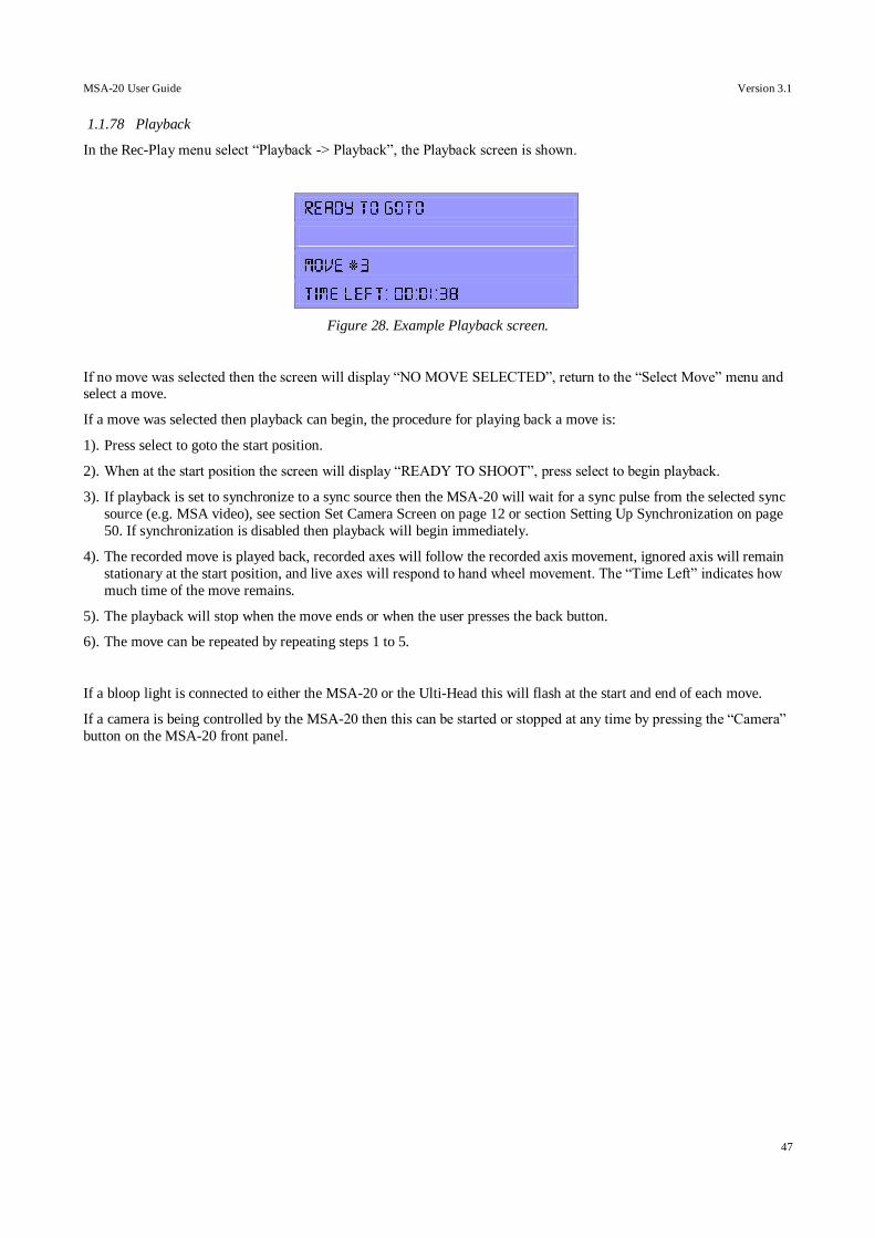
MSA-20 User Guide Version 3.1
47
1.1.78 Playback
In the Rec-Play menu select “Playback -> Playback”, the Playback screen is shown.
Figure 28. Example Playback screen.
If no move was selected then the screen will display “NO MOVE SELECTED”, return to the “Select Move” menu and select a move.
If a move was selected then playback can begin, the procedure for playing back a move is:
1). Press select to goto the start position.
2). When at the start position the screen will display “READY TO SHOOT”, press select to begin playback.
3). If playback is set to synchronize to a sync source then the MSA-20 will wait for a sync pulse from the selected sync
source (e.g. MSA video), see section Set Camera Screen on page 12 or section Setting Up Synchronization on page
50. If synchronization is disabled then playback will begin immediately.
4). The recorded move is played back, recorded axes will follow the recorded axis movement, ignored axis will remain
stationary at the start position, and live axes will respond to hand wheel movement. The “Time Left” indicates how
much time of the move remains.
5). The playback will stop when the move ends or when the user presses the back button.
6). The move can be repeated by repeating steps 1 to 5.
If a bloop light is connected to either the MSA-20 or the Ulti-Head this will flash at the start and end of each move.
If a camera is being controlled by the MSA-20 then this can be started or stopped at any time by pressing the “Camera”
button on the MSA-20 front panel.
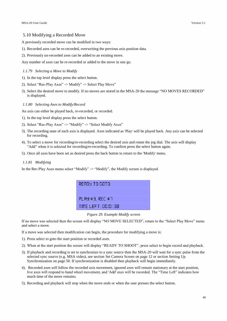
MSA-20 User Guide Version 3.1
48
5.10 Modifying a Recorded Move
A previously recorded move can be modified in two ways:
1). Recorded axes can be re-recorded, overwriting the previous axis position data.
2). Previously un-recorded axes can be added to an existing move.
Any number of axes can be re-recorded or added to the move in one go.
1.1.79 Selecting a Move to Modify
1). In the top level display press the select button.
2). Select “Rec-Play Axes” -> Modify” -> Select Play Move”
3). Select the desired move to modify. If no moves are stored in the MSA-20 the message “NO MOVES RECORDED”
is displayed.
1.1.80 Selecting Axes to Modify/Record
An axis can either be played back, re-recorded, or recorded.
1). In the top level display press the select button.
2). Select “Rec-Play Axes” -> “Modify” -> “Select Modify Axes”
3). The recording state of each axis is displayed. Axes indicated as 'Play' will be played back. Any axis can be selected
for recording.
4). To select a move for recording/re-recording select the desired axis and rotate the jog dial. The axis will display
“Add” when it is selected for recording/re-recording. To confirm press the select button again.
5). Once all axes have been set as desired press the back button to return to the 'Modify' menu.
1.1.81 Modifying
In the Rec-Play Axes menu select “Modify” -> “Modify”, the Modify screen is displayed.
Figure 29. Example Modify screen
If no move was selected then the screen will display “NO MOVE SELECTED”, return to the “Select Play Move” menu and select a move.
If a move was selected then modification can begin, the procedure for modifying a move is:
1). Press select to goto the start position or recorded axes.
2). When at the start position the screen will display “READY TO SHOOT”, press select to begin record and playback.
3). If playback and recording is set to synchronize to a sync source then the MSA-20 will wait for a sync pulse from the
selected sync source (e.g. MSA video), see section Set Camera Screen on page 12 or section Setting Up
Synchronization on page 50. If synchronization is disabled then playback will begin immediately.
4). Recorded axes will follow the recorded axis movement, ignored axes will remain stationary at the start position,
live axes will respond to hand wheel movement, and 'Add' axes will be recorded. The “Time Left” indicates how
much time of the move remains.
5). Recording and playback will stop when the move ends or when the user presses the select button.
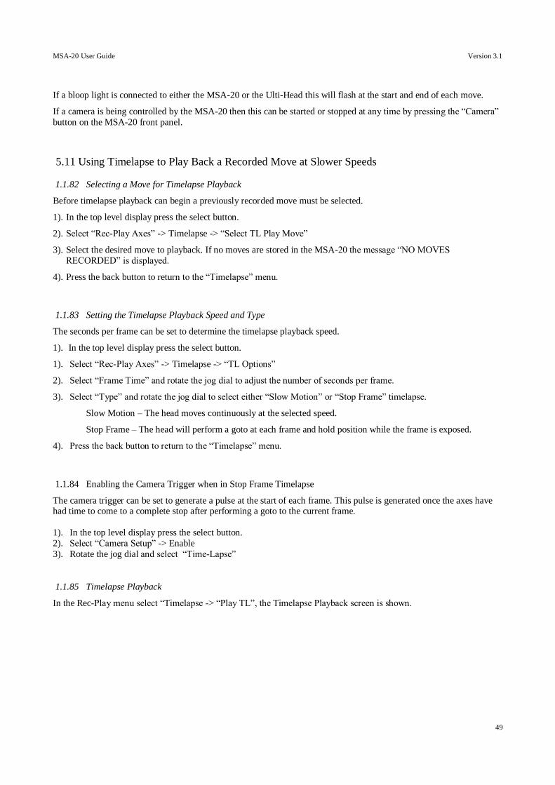
MSA-20 User Guide Version 3.1
49
If a bloop light is connected to either the MSA-20 or the Ulti-Head this will flash at the start and end of each move.
If a camera is being controlled by the MSA-20 then this can be started or stopped at any time by pressing the “Camera”
button on the MSA-20 front panel.
5.11 Using Timelapse to Play Back a Recorded Move at Slower Speeds
1.1.82 Selecting a Move for Timelapse Playback
Before timelapse playback can begin a previously recorded move must be selected.
1). In the top level display press the select button.
2). Select “Rec-Play Axes” -> Timelapse -> “Select TL Play Move”
3). Select the desired move to playback. If no moves are stored in the MSA-20 the message “NO MOVES
RECORDED” is displayed.
4). Press the back button to return to the “Timelapse” menu.
1.1.83 Setting the Timelapse Playback Speed and Type
The seconds per frame can be set to determine the timelapse playback speed.
1). In the top level display press the select button.
1). Select “Rec-Play Axes” -> Timelapse -> “TL Options”
2). Select “Frame Time” and rotate the jog dial to adjust the number of seconds per frame.
3). Select “Type” and rotate the jog dial to select either “Slow Motion” or “Stop Frame” timelapse.
Slow Motion – The head moves continuously at the selected speed.
Stop Frame – The head will perform a goto at each frame and hold position while the frame is exposed.
4). Press the back button to return to the “Timelapse” menu.
1.1.84 Enabling the Camera Trigger when in Stop Frame Timelapse
The camera trigger can be set to generate a pulse at the start of each frame. This pulse is generated once the axes have had time to come to a complete stop after performing a goto to the current frame.
1). In the top level display press the select button.
2). Select “Camera Setup” -> Enable
3). Rotate the jog dial and select “Time-Lapse”
1.1.85 Timelapse Playback
In the Rec-Play menu select “Timelapse -> “Play TL”, the Timelapse Playback screen is shown.
MSA-20 User Guide Version 3.1
50
Figure 30. Example Timelapse Playback screen.
If no move was selected then the screen will display “NO MOVE SELECTED”, return to the “Select TL Play Move”
menu and select a move.
If a move was selected then timelapse playback can begin, the procedure for playing back a move is:
1). Press select to goto the start position.
2). When at the start position the screen will display “READY TO SHOOT”, press select to begin timelapse playback.
3). If playback is set to synchronize to a sync source then the MSA-20 will wait for a sync pulse from the selected sync
source (e.g. MSA video), see section Set Camera Screen on page 12 or section Setting Up Synchronization on page
50. If synchronization is disabled then playback will begin immediately.
4). The recorded move is played back, recorded axes will follow the recorded axis movement but at a much slower
speed, ignored axis will remain stationary at the start position, and live axes will respond to hand wheel movement.
The “Time Left” indicates how much time of the move remains.
5). The playback will stop when the move ends or when the user presses the back button.
6). The move can be repeated by repeating steps 1 to 5.
If a bloop light is connected to either the MSA-20 or the Ulti-Head this will flash at the start and end of each move.
If a camera is being controlled by the MSA-20 then this can be started or stopped at any time by pressing the “Camera”
button on the MSA-20 front panel.
5.12 Setting Up Synchronization
A synchronization source can be used to trigger record and playback of moves on the MSA-20.
Synchronization sources are:
1). Disabled – Record/playback starts immediately without a sync pulse.
2). Ulti-Head – The first opto-isolated general purpose input on the Ulti-Head.
3). MSA Video – Video input (BNC) on the MSA-20 (odd-even signal)
4). MSA GPI 1/2/3/4 – One of 4 opto-isolated general purpose inputs on the MSA-20.
To change the record/playback synchronization source follow these steps:
1). In the top level display press select.
2). Select 'Set Camera'.
3). Select 'Cam Sync' at the bottom of the list.
4). Rotate the jog dial to select which input the record/playback should sync to and press select.
MSA-20 User Guide Version 3.1
51
5.13 Setting up the MSA-20 to Control a Camera
The MSA-20 can be used to control a camera in 2 ways.
1). To switch the camera on an off with either a continuous signal or an on/off pulse.
2). To directly control a camera motor, either a DC motor or a stepper motor.
There are 12 handwheel axes available on the MSA-20, the 12th handwheel axis is a virtual handwheel controlled by
software for use with camera motor axes. This axis is started and stopped using the 'Camera' button on the front panel of
the MSA-20.
1.1.86 Assigning the Camera Controller to a Motor Axis
1). In the top level display press the select button.
2). Select 'Set Axes' -> 'Set Controller'.
3). In the set controller screen scroll to the bottom of the list and select the 'Cam' controller.
4). Rotate the jog dial to change the motor to which the camera controller is assigned and press select. If using an Arri
Moco interface the camera controller should be assigned to motor axis 7, 'Cam', this is the first stepper motor output
on the Ulti-Head. For more information on assigning handwheels to motors see section Set Controller Screen on page 18.
1.1.87 Setting the Camera speed
1). In the top level display press the select button.
2). Select 'Set Camera'.
3). Select 'FPS', this is the Frames Per Second that the camera should run at.
4). Rotate the jog dial to change the FPS and press select.
5). Select 'LPF', this is the number of encoder lines (DC motor) or steps (Stepper motor) per frame that the camera will
turn through.
6). Rotate the jog dial to change the LPF and press select.
7). If the camera does not run at the required FPS then the LPF is incorrect. Rotate the jog dial to change the LPF and
press select.
8). If a camera is connected to the assigned motor axis, see section Assigning the Camera Controller to a Motor Axis on page 51, then pressing the 'Camera' button on the front panel of the MSA-20 will start and stop the camera.
5.14 Using Preston Lens Motors
Preston Lens motors can be used with the MSA-20 in record and playback. A move is recorded while the Preston Lens
motors are under the control of the Preston Hand Unit. During playback the MSA-20 takes control of the Preston Lens
motors and repeats the movement recorded from the Preston Hand Unit.
1). Setup Preston controls as normal with the Hand Unit controlling the MDR2 either wirelessly or wired.
2). Connect the MDR2 to the Ulti-Head via the serial connector (3-pin Lemo) using an MRMC cable.
3). Load the Ulti-Head as normal.
4). Select which axes you want to record, the Preston axes appear as the last 3 axes in the list of axes to record.
5). In the top level display press the select button.
6). Select 'Rec-Play Axes” -> “Record” -> “Select Rec Axes”.
7). Scroll down to the Preston axes e.g. “PN Zoom” at the bottom of the list.
8). Select the desired axis and rotate the job dial to change the recording mode to “Record” and press select.
MSA-20 User Guide Version 3.1
52
9). Record a move as normal using the MSA-20 to control the normal axes such as Pan and Tilt, and the Preston Hand
Unit to control the Preston motors.
10). Playback the move as normal.
11). When the move is played back the MSA-20 takes control of the Preston motors (the hand unit will have no control
during playback) and uses the recorded data to position the Preston motors.
12). When exiting playback the Preston Hand Unit regains control of the Preston motors which do a small goto to match
the Hand Unit positions.
5.15 Using Canon Lens Controls
When using the MSA-20 with the SFH-30 the system consists of 4 step and direction outputs and 4 analogue outputs.
Two of the step and direction output are used to drive the Pan and Tilt axes and 3 of the analogue output are used to
drive the Canon lens motors. The steps below explain how to setup the MSA-20 to control a Canon Lens (E.g.
KJ20X8.5B KTSM):
1). Setup the Canon lens controller as normal with the lens controller being powered from the camera.
2). Connect the lens controller to the SFH-30 control unit via the 12-pin Hirose connector.
3). Load the SFH-30 as normal.
4). The analogue axes that control the lens correspond to axes 5 to 8 (axes 1 to 4 are the stepper axes). You should
assign names like “Focus” and “Zoom” to these axes to identify them, see section Set Axis Name Screen on page 16.
5). Assign a controller (A handwheel or joystick) to the Canon lens axis, see section Set Controller Screen on page 18.
6). Remove any Front Panel Controls that are assigned to the controller as this will affect the controller to lens scaling,
see section Set Panel Controls Screen on 19.
7). If a controller is controlling the lens position (as opposed to the lens velocity in the case of speedboat inputs) then
the scaling has to be set to give control of the full range of movement. To do this you must set the Pot Range, see
section Set Pot Range Screen on page19. If the controller for an axis is changed then this step must be repeated to give
the correct scaling.
8). If a controller is controlling the lens velocity (as opposed to the lens position in the case of normal inputs) then the
axis scaling can be set manually to adjust the affect of the speedboat input on the lens velocity, see section Set Scales
Screen on page 15.
9). The Canon lens position is directly proportional to the Voltage applied to it. Since this is automatically limited it is
not necessary to use Soft Limits, to disable the soft limits see section Set Soft Limits Screen on page 15.
10). For the full range of travel of the lens to be achieved the lens must be calibrated. To do this rotate each controller
(handwheel etc) to its maximum travel in both directions.
11). If the lens is moving in the wrong direction then the axis direction can be changed to reverse the effect of the
handwheel movement on the lens, see section Set Direction Screen on page 16.
MSA-20 User Guide Version 3.1
53
5.16 Wireless Head Communication
The serial cable the connects the Ulti-Head to the MSA-20 can be replaced with 2 MRMC wireless modules. When the head is running from batteries this gives a completely wireless system with a range of up to 100m1.
The steps for connecting the wireless modules are as follows.
1.1.88 MSA-20
1) Unplug any serial cable plugged into “Serial B” (9-Way D-type female)
2) Plug the Wireless module into “GPIO1” (14-Way Lemo female)
3) Apply power to the MSA-20.
4) Verify that the “Power” (Blue) and “In Range” (Green) LEDs are lit. If the “In Range” LED is not lit then the
wrong wireless module is connected.
1.1.89 Ulti-Head
1) Unplug any serial cable plugged into the “Prog” connector on the Ulti-Head.
2) Plug the wireless module into the connector labeled “Cam Acc”.
3) Apply power to the Ulti-Head.
4) Verify that the “Power” (Blue) and “In Range” (Green) LEDs are lit. If the “In Range” LED is not lit then the
MSA-20 is not powered or the Ulti-Head is out of range of the MSA-20.
1. This is a preliminary value and is subject to change without notice.
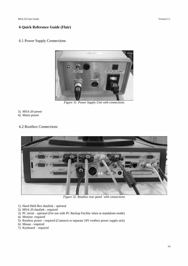
MSA-20 User Guide Version 3.1
54
6 Quick Reference Guide (Flair)
6.1 Power Supply Connections
3). MSA-20 power
4). Mains power
6.2 Rootbox Connections
1). Hand Held Box datalink - optional
2). MSA-20 datalink - required
3). PC serial – optional (For use with PC Backup Facility when in standalone mode)
4). Monitor -required
5). Rootbox power - required (Connects to separate 24V rootbox power supply unit)
6). Mouse - required
7). Keyboard – required
Figure 31. Power Supply Unit with connections
Figure 32. Rootbox rear panel with connections

MSA-20 User Guide Version 3.1
55
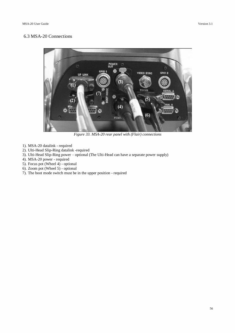
MSA-20 User Guide Version 3.1
56
6.3 MSA-20 Connections
1). MSA-20 datalink - required 2). Ulti-Head Slip-Ring datalink -required
3). Ulti-Head Slip-Ring power – optional (The Ulti-Head can have a separate power supply)
4). MSA-20 power - required
5). Focus pot (Wheel 4) - optional
6). Zoom pot (Wheel 5) - optional
7). The boot mode switch must be in the upper position - required
Figure 33. MSA-20 rear panel with (Flair) connections
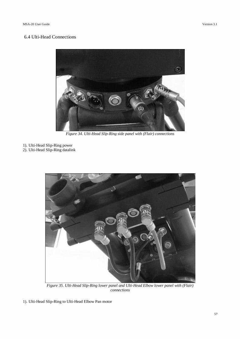
MSA-20 User Guide Version 3.1
57
6.4 Ulti-Head Connections
1). Ulti-Head Slip-Ring power 2). Ulti-Head Slip-Ring datalink
1). Ulti-Head Slip-Ring to Ulti-Head Elbow Pan motor
Figure 34. Ulti-Head Slip-Ring side panel with (Flair) connections
Figure 35. Ulti-Head Slip-Ring lower panel and Ulti-Head Elbow lower panel with (Flair) connections

MSA-20 User Guide Version 3.1
58
2). Ulti-Head Slip-Ring to Ulti-Head Elbow power
3). Ulti-Head Slip-Ring to Ulti-Head Elbow datalink
MSA-20 User Guide Version 3.1
59
6.5 Power Up
See sections 5.1 5.1 Power Supply Connections to Ulti-Head Connections above on pages 54 to 57 for connection
information.
Once everything is connected the mains power and 34VDC switches on the PSU and can be turned on and the rootbox
power supply can be plugged in. The power-up checklist is:
1). 1 Green 'Power' LED on the Rootbox power supply is on.
2). 1 Yellow '5V' LED and 1 Green '12V' LED on the Rootbox rear panel are on.
3). 1 Blue 'Power' LED and 1 Yellow 'Inhibit' LED on the Rootbox front panel are on.
4). 1 Red LED on Power Supply Unit is on.
5). 1 Blue 'Power' LED, and 1 Yellow 'Inhibit' LED on MSA-20 front panel are on.
6). 4 Blue 'Power' LEDs and 1 Yellow 'Inhibit' LED on the Ulti-Head upper panel are on.
6.6 Using Flair
1). Once the Rootbox has finished booting Windows Flair can be started, click on the 'Flair' desktop shortcut.
2). The Rootbox will issue a reset, this is indicated by the Yellow 'Reset' LED on all boards connected to the Rootbox
and the Yellow 'Reset' LED on the Rootbox front panel illuminating.
3). The system will then be booted, all boards will show a flashed Green 'Running' LED when they are receiving boot
data and will flash at a constant 25Hz when up and running.
4). Once all the boards have been booted Flair will start running, this is indicated by the Yellow 'Inhibit' LED on all
boards and on the Rootbox front panel switching off.
5). Flair is now running. Please refer to the Flair manual for detailed information on how to use Flair.
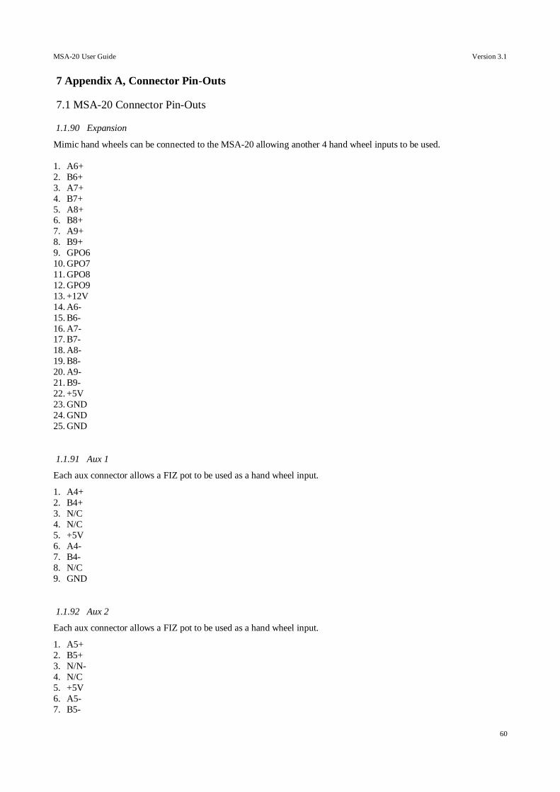
MSA-20 User Guide Version 3.1
60
7 Appendix A, Connector Pin-Outs
7.1 MSA-20 Connector Pin-Outs
1.1.90 Expansion
Mimic hand wheels can be connected to the MSA-20 allowing another 4 hand wheel inputs to be used.
1. A6+
2. B6+
3. A7+
4. B7+
5. A8+ 6. B8+
7. A9+
8. B9+
9. GPO6
10. GPO7
11. GPO8
12. GPO9
13. +12V
14. A6-
15. B6-
16. A7- 17. B7-
18. A8-
19. B8-
20. A9-
21. B9-
22. +5V
23. GND
24. GND
25. GND
1.1.91 Aux 1
Each aux connector allows a FIZ pot to be used as a hand wheel input.
1. A4+
2. B4+
3. N/C
4. N/C
5. +5V
6. A4-
7. B4-
8. N/C
9. GND
1.1.92 Aux 2
Each aux connector allows a FIZ pot to be used as a hand wheel input.
1. A5+
2. B5+
3. N/N-
4. N/C
5. +5V
6. A5-
7. B5-
MSA-20 User Guide Version 3.1
61
8. N/C
9. GND
1.1.93 Serial A
Serial A connects the MSA-20 (Standalone Mode) to the Ulti-Head via RS232. This is the connection that provides
booting of the Ulti-head and subsequent communication. Baud rate 76.8kbps.
1. N/C
2. TX-A 3. RX-A
4. N/C
5. GND
6. N/C
7. N/C
8. N/C
9. N/C
1.1.94 Serial B
Serial B connects the MSA-20 to the Move Archiver software running on a Windows PC. The Move Archiver software
lets the user backup the recorded moves that are stored in NVRAM (non-volatile random access memory) in the MSA-20. Baud rate 38.4kbps.
1. N/C
2. TX-B
3. RX-B
4. N/C
5. GND
6. N/C
7. N/C
8. N/C
9. N/C
1.1.95 Up Link
The Up link connects the MSA-20 (Flair Mode) to the Flair Root Box. The Up link boots the MSA-20 from Flair and
provides subsequent communication. Bit rate 10Mbps.
1. Watchdog-
2. In-
3. Out-
4. N/C
5. N/C
6. Watchdog+
7. In+
8. Out+
9. N/C
1.1.96 Down Link
The Down link connects the MSA-20 (Flair Mode) to the next axis card in the pipe. This can be an type of axis card,
e.g. A Quad-Axis card or an Ulti-Axis card. Bit rate 10Mbps.
1. Watchdog-
2. Out-
3. In-
4. N/C
MSA-20 User Guide Version 3.1
62
5. N/C
6. Watchdog+
7. Out+
8. In+
9. N/C
1.1.97 GPIO1
2 general purpose optically isolated inputs and 1 general purpose optically isolated output (open collector) are available. This is pin compatible with the GPIO connector on the Ulti-Head and can be used with the Bloop light. The inputs can
be used a sync inputs for record and playback.
1. N/C
2. GPI2
3. N/C
4. SerialTxB (MK4 Onwards)
5. N/C
6. SerialRxB (MK4 Onwards)
7. N/C
8. GND
9. +5V 10. GPI1
11. N/C
12. N/C
13. GPO2-collector (MK4 Onwards)
14. GPO1-collector
1.1.98 GPIO2
4 general purpose optically isolated inputs and 1 general purpose optically isolated output (open collector) are available.
The inputs can be used a sync inputs for record and playback.
1. +5V
2. GND
3. GPI1 4. GPI2
5. GPI3
6. GPI4
7. GPO-collector
8. GND
9. N/C
10. N/C
1.1.99 Video In
The video syncing input lets the MSA-20 sync to a video source.
1. Video 2. GND
1.1.100 Boot Mode
The boot mode switch is used to select the MSA-20 boot mode (Flair Mode, Standalone Mode, or Serial Mode).
Top – Internal Flash
Middle – Flair (Up Link)
Bottom – Serial Port A

MSA-20 User Guide Version 3.1
63
1.1.101 Power In
Power to supply the MSA-20 and the power output connector. The MSA-20 can run from 12VDC-35VDC.
1. GND
2. +VIN
3. N/C
1.1.102 Power Out
1. GND 2. +VIN
3. N/C
7.2 Ulti-Head Connector Pin-Outs
1.1.103 Motor (Pan/Aux2/Aux1/Tilt/Focus/Zoom)
1 - DATUM 2 - A+
3 - B+
4 - Z+
5 - N/C
6 - MOTOR_B
7 - MOTOR_A
8 - LIMIT
9 - +5V
10 - GND
1.1.104 Power
1 - GND
2 - GND 3 - +35V
4 - +35V
1.1.105 Data
1 - Watchdog-
2 - Link1Out-
3 - Link1Out+
4 - Link1In-
5 - Link1In+
6 - Watchdog+
1.1.106 Camera Accessory
1 - Step1 2 - Gp2In
3 - Step2
4 - SerialTxB
5 - Step3
6 - SerialRxB
7 - Dir3
8 - GND
9 - +5V
10 - Gp1In
11 - Dir1
12 - Dir2
13 - Gp2Out
MSA-20 User Guide Version 3.1
64
14 - Gp1Out
1.1.107 Serial
1 - SerialTxA
2 - SerialRxA
3 - +5V
4 - FGPIO
5 - DSP_TRSTN
6 - TCK 7 - TMS
8 - DSP_TDI
9 - DSP_TDO
10 - DSP_EMU0
11 - DSP_EMU1
12 - FPGA_TDI
13 - FPGA_TDO
14 - BOOT_SEL
15 - +3.3V
16 - GND
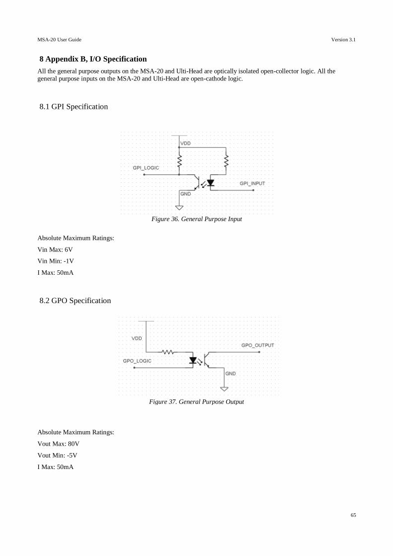
MSA-20 User Guide Version 3.1
65
8 Appendix B, I/O Specification
All the general purpose outputs on the MSA-20 and Ulti-Head are optically isolated open-collector logic. All the general purpose inputs on the MSA-20 and Ulti-Head are open-cathode logic.
8.1 GPI Specification
Absolute Maximum Ratings:
Vin Max: 6V
Vin Min: -1V
I Max: 50mA
8.2 GPO Specification
Absolute Maximum Ratings:
Vout Max: 80V
Vout Min: -5V
I Max: 50mA
Figure 36. General Purpose Input
Figure 37. General Purpose Output