Embed Size (px)
Citation preview
Fastener Modeling for Joining Composite Parts
Alexander Rutman, Associate Technical Fellow, Spirit AeroSystems
Chris Boshers, Stress Engineer, Spirit AeroSystemsJohn Parady, Principal Application Engineer, MSC.SoftwareLarry Pearce, Senior Lead Application Engineer, MSC.Software
AM-VPD09-006
References
• Fastener Modeling for Joining Composite Parts, Alexander Rutman, Chris Boshers (Spirit AeroSystems), Larry Pearce, John Parady (MSC.Software Corporation), To Be Presented at the 2009 Americas Virtual Product Development Conference, April 21-22, 2009, Phoenix, AZ
• Fastener Modeling for Joining Parts Modeled by Shell and Solid Elements, Alexander Rutman, Chris Boshers (Spirit AeroSystems), Larry Pearce, John Parady (MSC.Software Corporation), 2007 Americas Virtual Product Development Conference, October 11-12, 2007, Detroit, MI
• Fastener Modeling for MSC.Nastran Finite Element Analysis, Alexander Rutman, Adrian Viisoreanu (Boeing), John Parady (MSC.Software Corporation), 2000 World Aviation Conference, October 10-12, 2000, AIAA-2000-01-5585
Objective
• Accurately represent fastener behavior
• Rapid model preparation of each fastener
• Can be used with parts modeled by shell elements with isotropic or orthotropic material properties, parts modeled by solid elements with isotropic properties, or any combination of these parts
• Accounts for the effects of variable bearing stiffness of a fastener -composite plate interface
Develop an FEM representation of a fastener installed through multiple metal and composite plates.
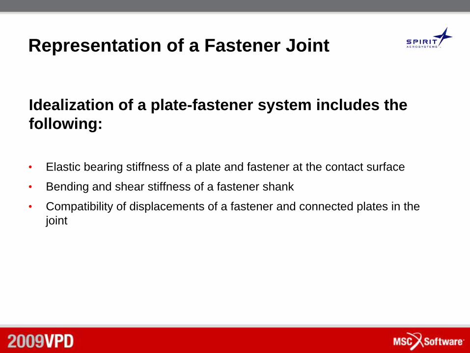
Representation of a Fastener Joint
• Elastic bearing stiffness of a plate and fastener at the contact surface
• Bending and shear stiffness of a fastener shank
• Compatibility of displacements of a fastener and connected plates in the joint
Idealization of a plate-fastener system includes the following:
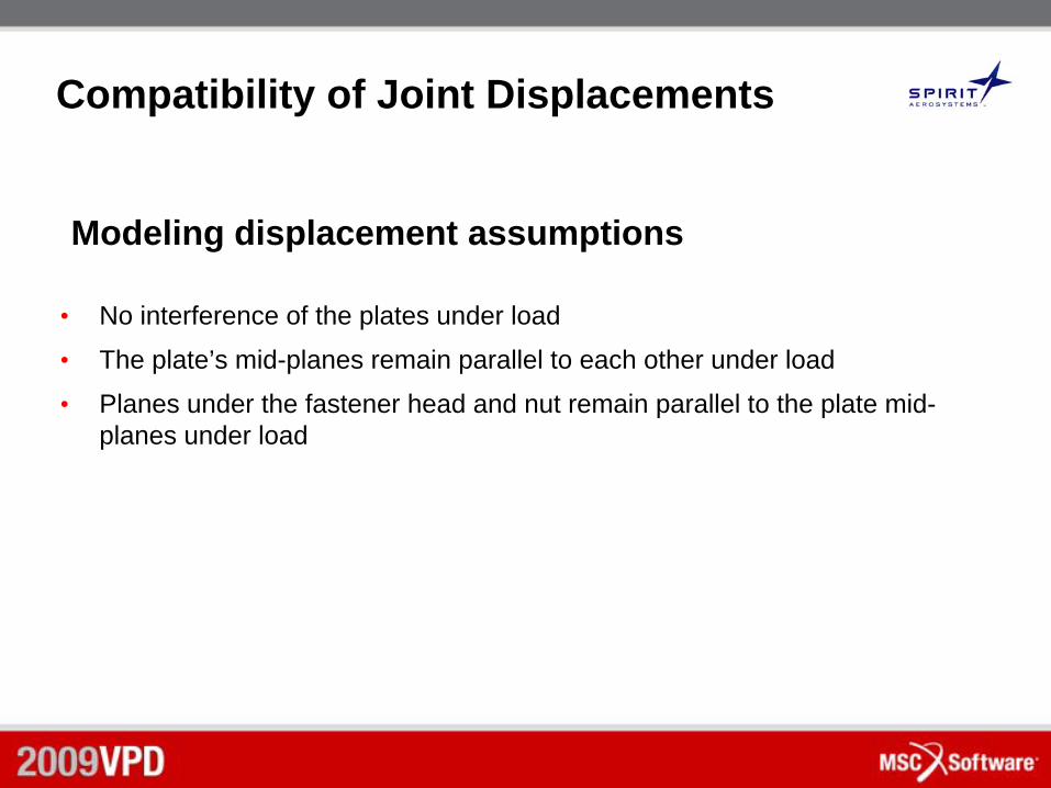
Compatibility of Joint Displacements
• No interference of the plates under load
• The plate’s mid-planes remain parallel to each other under load
• Planes under the fastener head and nut remain parallel to the plate mid-planes under load
Modeling displacement assumptions
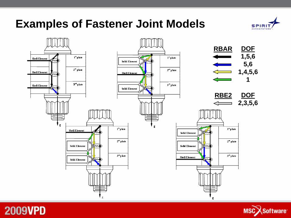
Examples of Fastener Joint Models
DOF1,5,65,6
1,4,5,61
DOF2,3,5,6
RBAR
RBE2
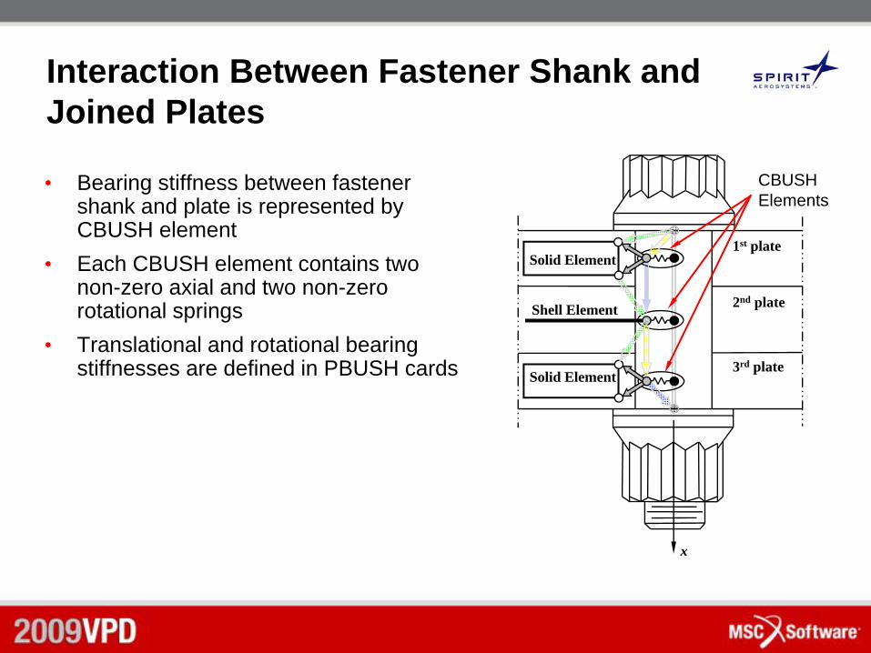
Interaction Between Fastener Shank and Joined Plates
• Bearing stiffness between fastener shank and plate is represented by CBUSH element
• Each CBUSH element contains two non-zero axial and two non-zero rotational springs
• Translational and rotational bearing stiffnesses are defined in PBUSH cards
1st plate
2nd plate
3rd plate
Solid Element
x
Shell Element
Solid Element
CBUSHElements
Fastener
1st plate
2nd plate
3rd plate
4th plate
fd
1pt
2pt
3pt
4pt
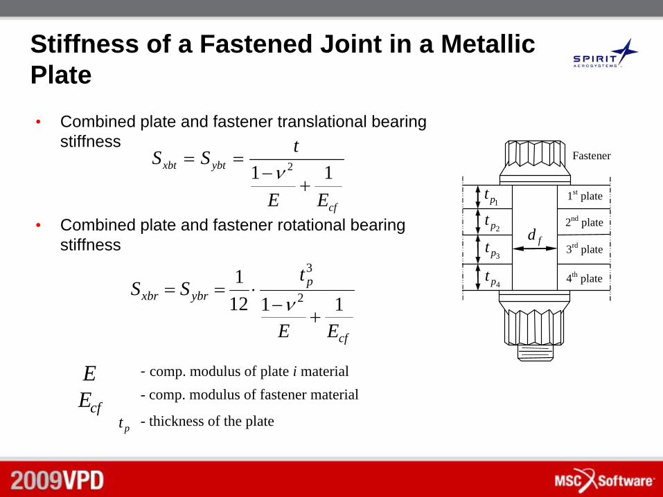
Stiffness of a Fastened Joint in a Metallic Plate• Combined plate and fastener translational bearing
stiffness
• Combined plate and fastener rotational bearing stiffness
E - comp. modulus of plate i material- comp. modulus of fastener material
- thickness of the platecfE
pt
cf
pybrxbr
EE
tSS
11121
2
3
+−⋅==
ν
cf
ybtxbt
EE
tSS11 2
+−
==ν
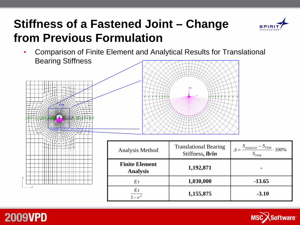
Stiffness of a Fastened Joint – Change from Previous Formulation
• Comparison of Finite Element and Analytical Results for Translational Bearing Stiffness
%100⋅−
=FEM
FEManalytical
SSS
Δ
tE
21 ν−tE
Analysis Method Translational Bearing Stiffness, lb/in
Finite Element Analysis 1,192,871 -
1,030,000 -13.65
1,155,875 -3.10
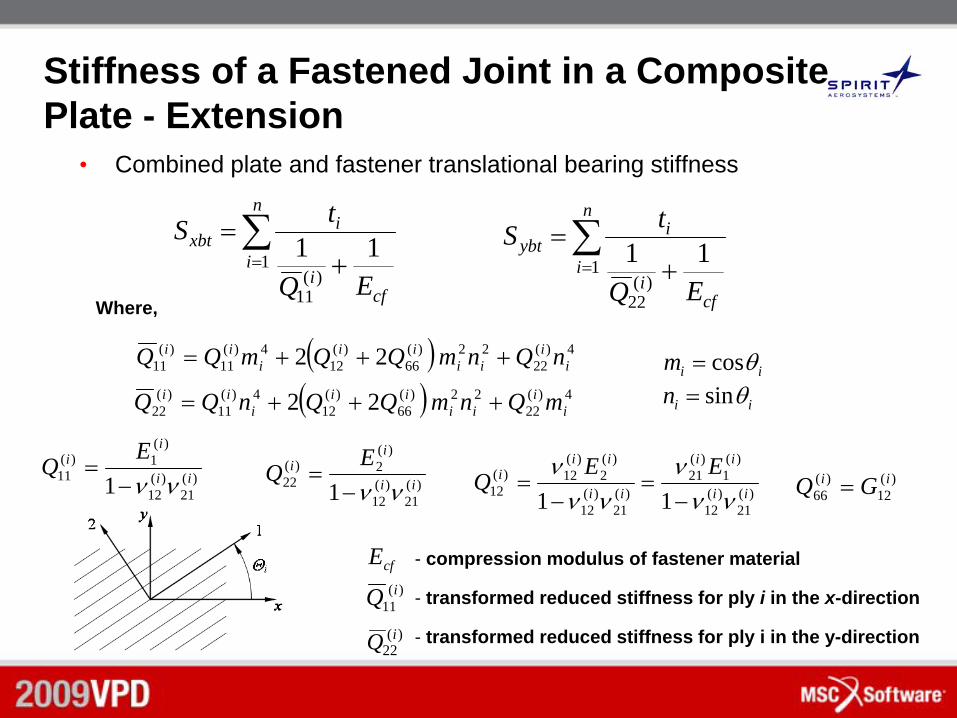
Stiffness of a Fastened Joint in a Composite Plate - Extension
• Combined plate and fastener translational bearing stiffness
∑= +
=n
i
cfi
ixbt
EQ
tS1
)(11
11 ∑= +
=n
i
cfi
iybt
EQ
tS1
)(22
11
)(11
iQ
( ) 4)(22
22)(66
)(12
4)(11
)(11 22 i
iii
iii
ii nQnmQQmQQ +++=
- compression modulus of fastener material
- transformed reduced stiffness for ply i in the x-direction
- transformed reduced stiffness for ply i in the y-direction
cfE
)(22
iQ
( ) 4)(22
22)(66
)(12
4)(11
)(22 22 i
iii
iii
ii mQnmQQnQQ +++=
)(21
)(12
)(1)(
11 1 ii
ii E
Qνν−
=)(
21)(
12
)(2)(
22 1 ii
ii E
Qνν−
=)(
21)(
12
)(1
)(21
)(21
)(12
)(2
)(12)(
12 11 ii
ii
ii
iii EE
Qνν
ννν
ν−
=−
= )(12
)(66
ii GQ =
iim θcos=
iin θsin=
Where,
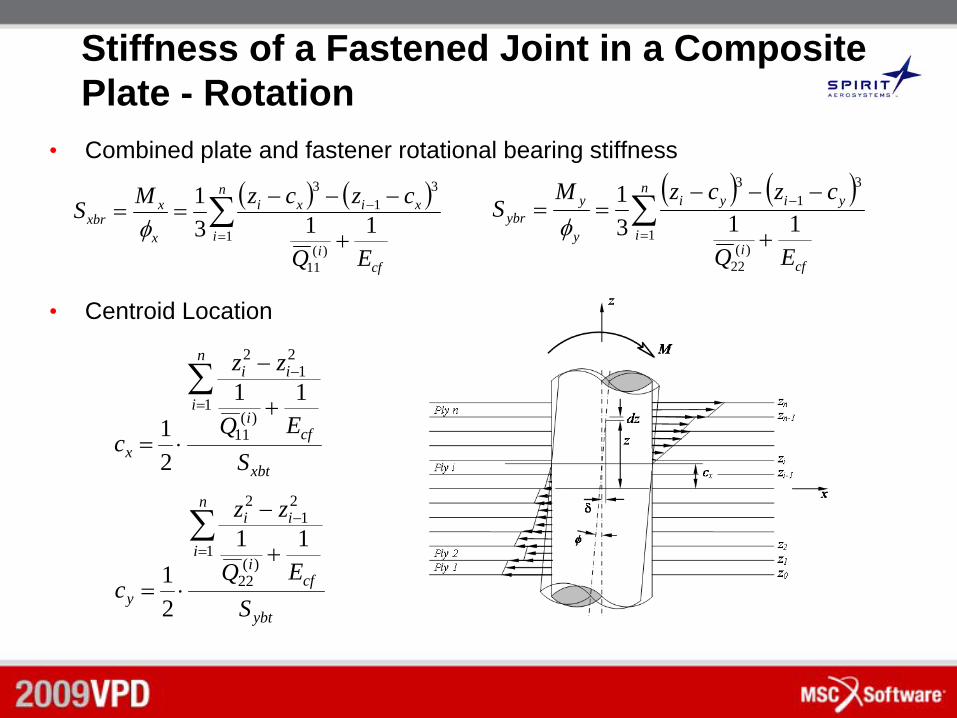
Stiffness of a Fastened Joint in a Composite Plate - Rotation
• Combined plate and fastener rotational bearing stiffness
• Centroid Location
( ) ( )∑=
−
+
−−−==
n
i
cfi
xixi
x
xxbr
EQ
czczMS1
)(11
31
3
1131
φ( ) ( )
∑=
−
+
−−−==
n
i
cfi
yiyi
y
yybr
EQ
czczMS
1)(
22
31
3
1131
φ
xbt
n
i
cfi
ii
x SEQ
zz
c
∑=
−
+
−
⋅=
1)(
11
21
2
11
21
ybt
n
i
cfi
ii
y SEQ
zz
c
∑=
−
+
−
⋅=
1)(
22
21
2
11
21
Analysis Procedure and Limitations
• The bearing stiffness in the joint depends on the direction of the fastener reactions. Because these directions are not known prior to running the model, an iterative procedure is required to accurately determine fastener reactions.
• For composite plates with variable in-plane stiffnesses, the spring analogy used in this analysis does not take coupling between transverse displacements into account. The error induced by this approximation is expected to be small and will decrease with each iteration.
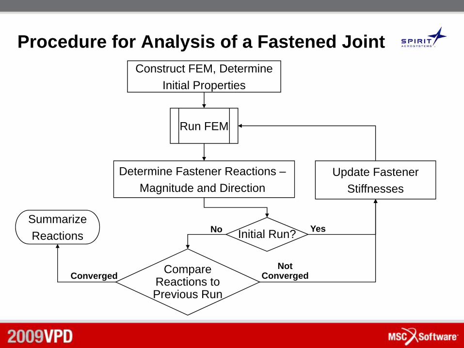
Procedure for Analysis of a Fastened JointConstruct FEM, Determine
Initial Properties
Determine Fastener Reactions –Magnitude and Direction
Run FEM
CompareReactions toPrevious Run
SummarizeReactions
Update FastenerStiffnesses
ConvergedNot
Converged
Initial Run? YesNo
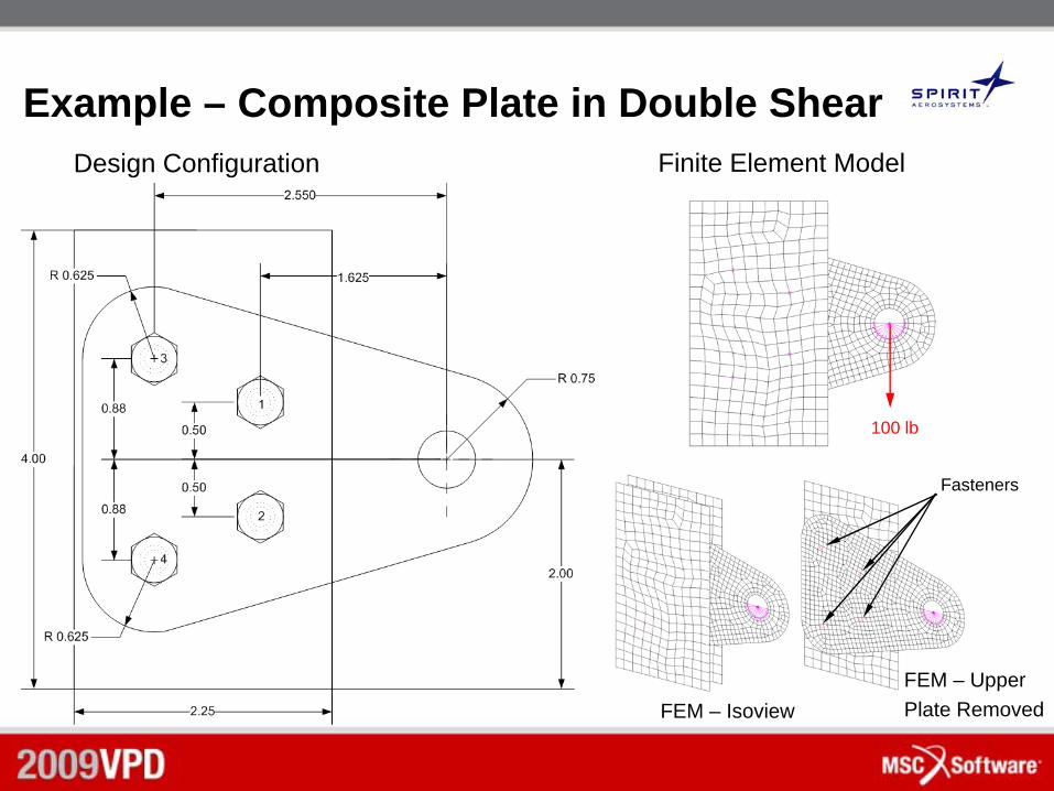
Example – Composite Plate in Double ShearDesign Configuration
FEM – UpperPlate RemovedFEM – Isoview
Fasteners
Finite Element Model
100 lb
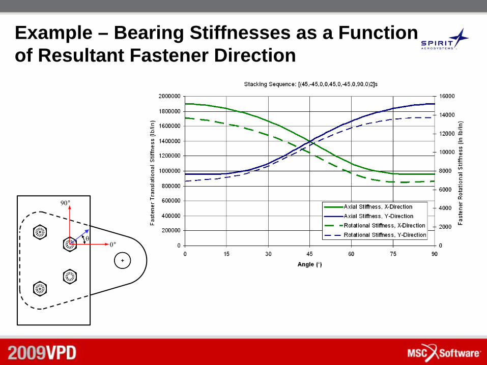
Example – Bearing Stiffnesses as a Function of Resultant Fastener Direction
θ0°
90°
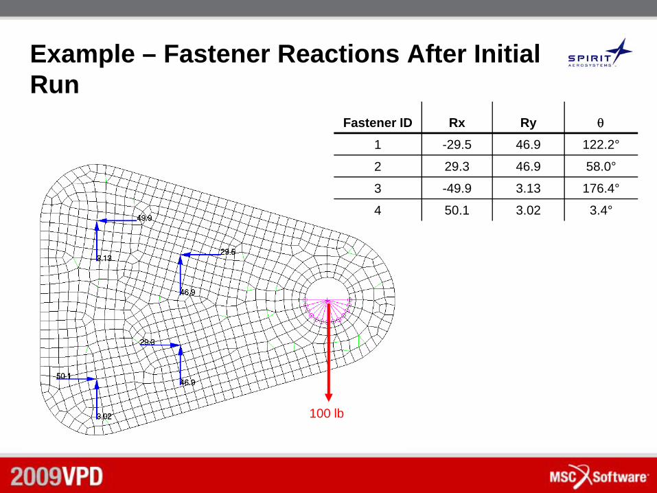
Example – Fastener Reactions After Initial Run
Fastener ID Rx Ry θ
1 -29.5 46.9 122.2°
2 29.3 46.9 58.0°
3 -49.9 3.13 176.4°
4 50.1 3.02 3.4°
100 lb
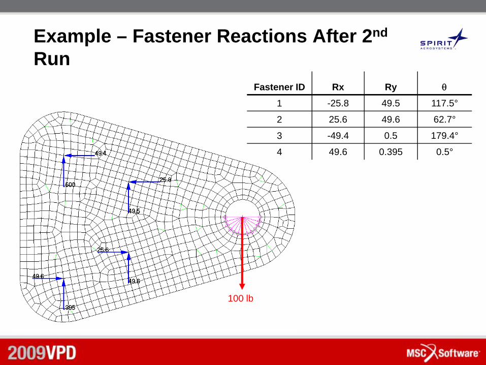
Example – Fastener Reactions After 2nd
RunFastener ID Rx Ry θ
1 -25.8 49.5 117.5°
2 25.6 49.6 62.7°
3 -49.4 0.5 179.4°
4 49.6 0.395 0.5°
100 lb
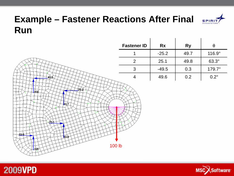
Example – Fastener Reactions After Final Run
Fastener ID Rx Ry θ
1 -25.2 49.7 116.9°
2 25.1 49.8 63.3°
3 -49.5 0.3 179.7°
4 49.6 0.2 0.2°
100 lb
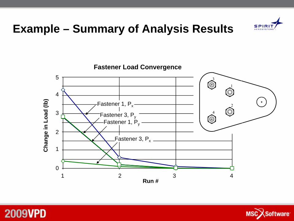
Example – Summary of Analysis Results
Fastener Load Convergence
0
1
2
3
4
5
1 2 3Run #
Cha
nge
in L
oad
(lb)
Fastener 1, Px
Fastener 1, Py
Fastener 3, Px
Fastener 3, Py
4
1
2
3
4
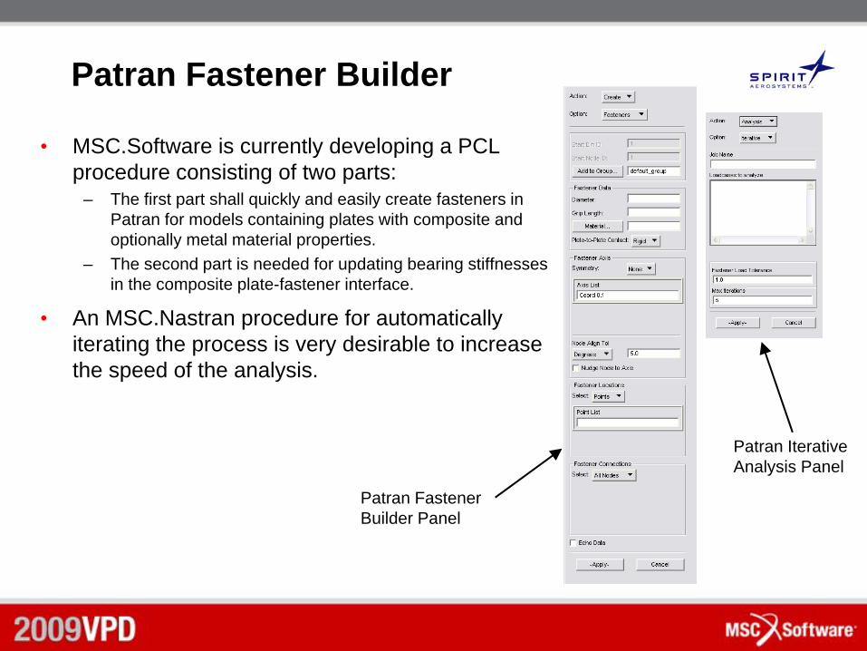
Patran Fastener Builder
• MSC.Software is currently developing a PCL procedure consisting of two parts:
– The first part shall quickly and easily create fasteners in Patran for models containing plates with composite and optionally metal material properties.
– The second part is needed for updating bearing stiffnesses in the composite plate-fastener interface.
• An MSC.Nastran procedure for automatically iterating the process is very desirable to increase the speed of the analysis.
Patran Fastener Builder Panel
Patran Iterative Analysis Panel
Conclusions
• The fastener modeling technique developed for isotropic materials has been extended to models containing composite plates.
• The previous formulae for computing bearing stiffnesses for fasteners in a metal plate has been modified to better account for plate behavior.
• Due to the variation of in-plane stiffnesses of a composite material, an iterative procedure is necessary to accurately determine fastener loads.
• An automated PCL procedure is under development to quickly and easily create fastener representations in MSC Patran.
13/05/2009 22
Contact Details :
• For further information please contact
Alexander [email protected]
Chris [email protected]
Spirit AeroSystemsP.O. Box 780008Mail Zone K78-20Wichita KS, 67230USA
John Parady817-481-4812, ext. [email protected]
Larry [email protected]
MSC.Software2 MacArthur PlaceSanta Ana, CA 92707USA