Embed Size (px)
Citation preview

Multiagent Control of Traffic Signals Project Plan 1.0
Page 1 of 12
Project Plan
For Multiagent Control of Traffic Signals
Version 1.0
Submitted in partial fulfillment of the requirements of the degree of MSE
Bryan Nehl
CIS 895 – MSE Project
Kansas State University
Multiagent Control of Traffic Signals Project Plan 1.0
Page 2 of 12
Table of Contents
1 Introduction ............................................................................................................................. 4
1.1 References ........................................................................................................................ 4
1.2 Terms ................................................................................................................................ 4
2 Cost Estimate .......................................................................................................................... 5
2.1 COCOMO 2.0 .................................................................................................................. 5
2.1.1 Computing Unadjusted Function Points ................................................................... 5
2.1.2 Estimate Variables .................................................................................................... 6
2.1.3 Time to develop equation.......................................................................................... 6
2.1.4 Early Design Calculations......................................................................................... 7
2.1.5 Discussion ................................................................................................................. 8
3 Architecture Elaboration Plan ................................................................................................. 8
3.1 Revise Vision Document .................................................................................................. 8
3.2 Revise Project Plan........................................................................................................... 8
3.3 Create Formal Specification ............................................................................................. 8
3.4 Create Architectural Design ............................................................................................. 8
3.5 Create Test Plan ............................................................................................................... 8
3.6 Conduct Technical Inspection .......................................................................................... 8
3.7 Create Executable Architecture Prototype ....................................................................... 8
4 Implementation Plan: Deliverables ......................................................................................... 9
4.1 Action Items ..................................................................................................................... 9
4.2 Technical Inspection Letters ............................................................................................ 9
4.3 Component Design Document ......................................................................................... 9
4.4 User Manual ..................................................................................................................... 9
4.5 Source Code ..................................................................................................................... 9
4.6 Assessment Evaluation ..................................................................................................... 9
4.7 Project Evaluation ............................................................................................................ 9
4.8 References ........................................................................................................................ 9
5 Implementation Plan: Work Breakdown Structure ............................................................... 10
5.1 Inception Phase .............................................................................................................. 10
5.2 Project Spike Explorations ............................................................................................. 11
5.3 Project Risk Management .............................................................................................. 11
5.4 Elaboration Phase ........................................................................................................... 11
5.5 Construction Phase ......................................................................................................... 11

Multiagent Control of Traffic Signals Project Plan 1.0
Page 3 of 12
5.6 Project Maintenance ....................................................................................................... 12

Multiagent Control of Traffic Signals Project Plan 1.0
Page 4 of 12
1 Introduction This is the initial project plan for the Multiagent Control of Traffic Signals (MACTS) Masters of
Software Engineering project.
1.1 References 1. W. Royce, Software Project Management: A Unified Framework, Addison-Wesley,
1998, p. 34, pp. 265-281.
2. B. Boehm et al., “Cost Models for Future Software Processes: COCOMO 2.0,” Annals of
Software Eng., Vol. 1, 1995, pp. 57-94.
3. K-State Master of Software Engineering web site, “MSE Portfolio Requirements,”
4. November 28, 2011; http://mse.cis.ksu.edu/portfolio.html.
5. Center for Systems and Software Engineering web site, “COCOMO II,” December 4,
2011: http://sunset.usc.edu/csse/research/COCOMOII/cocomo_main.html.
6. The Code Project web site, “Software Project Cost Estimates Using COCOMO II
Model,” December 4, 2011: http://www.codeproject.com/KB/architecture/cocomo2.aspx.
7. Naval Postgraduate School web site, “COCOMO II - Constructive Cost Model,”
December 4, 2011: http://diana.nps.edu/~madachy/tools/COCOMOII.php.
8. Center for Software Engineering, USC, COCOMO II: Model Definition Manual Version
2.1, 2000.
9. The Code Project web site, “Calculating Function Points,” December 4, 2011:
http://www.codeproject.com/KB/architecture/Calculate_Function_Point.aspx.
10. USC Center for Software Engineering website, “COCOMO II Affiliates,” December 4,
2011:
http://csse.usc.edu/csse/affiliate/private/COCOMOII_Driver+Calc_Ss/SpreadSheet-
COCOMOII.html.
1.2 Terms COCOMO is short for COnstructive COst MOdel.
SLOC is an acronym for Source Lines Of Code. These are lines of code that are neither
comment nor whitespace.
UFP is an acronym for Unadjusted Function Points.
Data Functionality
Internal Logical Files (ILF) are files that represent major logical groupings of systems data that
are persisted.
External Interface Files (EIF) are files that are shared between software systems.
Transaction Functionality
External Inputs (EI) represent data that enters into the system.
External Outputs (EO) represent data that exits or is output by the system.
External Queries (EQ) are counted by examining portions of the system that accept an input and
respond immediately with some form of output.
TraCI is the short term for Traffic Control Interface.
SUMO is short for Simulation for Urban MObility.

Multiagent Control of Traffic Signals Project Plan 1.0
Page 5 of 12
2 Cost Estimate
2.1 COCOMO 2.0
2.1.1 Computing Unadjusted Function Points
Unadjusted function points are used in the early design stage for project estimation. I followed
the information I found about computing function points on the Code Project website[9].
Additional information included definitions of the function point types can be found in section
2.2 of COCOMO II: Model Definition Manual[8]. I reviewed my use cases and arrived at the
following table:
Use Case ILF EIF EI EO EQ Total
1 2 1 2 2 2 3 1 1 4 1 1 5 1 1 1 1 6 1 7 1 1 1 1 8 1 1 9 1 1 10 1 1 11 1 1 1 1
Sub Total 9 3 2 11 5 All weights
Low
7 5 3 4 3
weighted 63 15 6 44 15 128

Multiagent Control of Traffic Signals Project Plan 1.0
Page 6 of 12
2.1.2 Estimate Variables
Cost
Driver
Value (Text) Factor Description
LANG Hybrid 3rd
/4th
Python 50 Used for converting from UFP to SLOC
PREC Nominal 3.72 Precedentedness
FLEX High 2.03 Development Flexibility
RELY Very High 5 Required Software Reliability
DATA Low 2 Data Size
CPLX Nominal 4 Product Complexity
RUSE Low 0.95 Required reusability
DOCU Nominal 3 Documentation to match life cycle needs
RESL High 1.41 Architecture and risk resolution
TEAM High 2.19 Team Cohesion
ACAP High 4 Analyst Capability
PCAP High 4 Programmer Capability
PCON Very High 5 Personnel Capability
APEX Nominal 3 Application Experience
PLEX Nominal 3 Platform Experience
LTEX Low 2 Language and Tool Experience
PMAT High 3.12 Process Maturity
TIME Very High 5 Execution Time
STOR Nominal 3 Main Storage Constraint
PVOL Low 2 Platform Volatility
TOOL Nominal 3 Use of Software Tools
SITE Extra High 6 Multisite Development
SCED Nominal 1.00 Schedule
2.1.3 Time to develop equation
This model is explained in Section 4 of the COCOMO II Design Model Definition document [8].
(Equation 1)
[ ( ) ]
( [ ]) Symbol Description B The scaling base-exponent for the effort equation, currently set to 0.91 C Coefficient that can be calibrated currently set to 3.67 D Scaling base-exponent that can be calibrated currently set to 0.28 E The scaling exponent for the effort equation PMNS Person-Months estimated without the SCED cost driver (Nominal Schedule) SCED Required Schedule Compression TDEV Time to Develop in calendar months
Multiagent Control of Traffic Signals Project Plan 1.0
Page 7 of 12
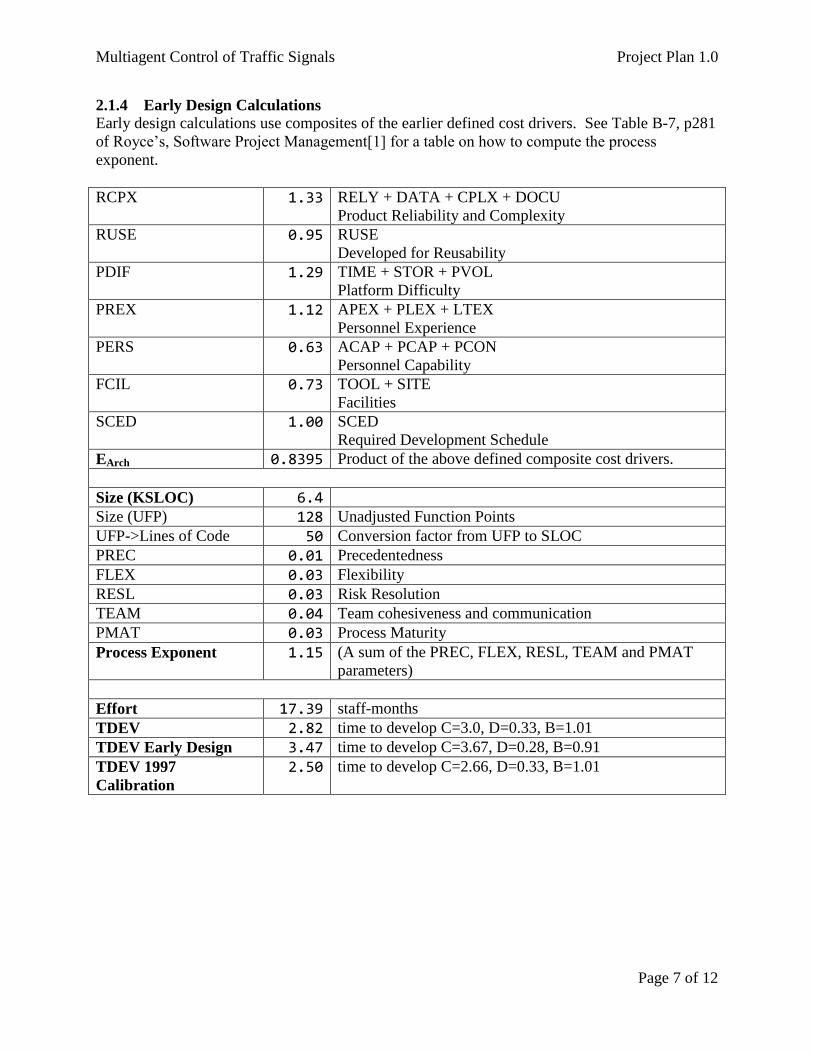
2.1.4 Early Design Calculations
Early design calculations use composites of the earlier defined cost drivers. See Table B-7, p281
of Royce’s, Software Project Management[1] for a table on how to compute the process
exponent.
RCPX 1.33 RELY + DATA + CPLX + DOCU
Product Reliability and Complexity
RUSE 0.95 RUSE
Developed for Reusability
PDIF 1.29 TIME + STOR + PVOL
Platform Difficulty
PREX 1.12 APEX + PLEX + LTEX
Personnel Experience
PERS 0.63 ACAP + PCAP + PCON
Personnel Capability
FCIL 0.73 TOOL + SITE
Facilities
SCED 1.00 SCED
Required Development Schedule
EArch 0.8395 Product of the above defined composite cost drivers.
Size (KSLOC) 6.4
Size (UFP) 128 Unadjusted Function Points
UFP->Lines of Code 50 Conversion factor from UFP to SLOC
PREC 0.01 Precedentedness
FLEX 0.03 Flexibility
RESL 0.03 Risk Resolution
TEAM 0.04 Team cohesiveness and communication
PMAT 0.03 Process Maturity
Process Exponent 1.15 (A sum of the PREC, FLEX, RESL, TEAM and PMAT
parameters)
Effort 17.39 staff-months
TDEV 2.82 time to develop C=3.0, D=0.33, B=1.01
TDEV Early Design 3.47 time to develop C=3.67, D=0.28, B=0.91
TDEV 1997
Calibration
2.50 time to develop C=2.66, D=0.33, B=1.01
Multiagent Control of Traffic Signals Project Plan 1.0
Page 8 of 12
2.1.5 Discussion
I computed the TDEV estimate with three different sets of constants. The results ranged from
2.5 to 3.47. This seems reasonable.
I had to be a little creative with the UFP to SLOC conversion because Python wasn’t listed in the
documentation. I did some research and while Python is sort of 3rd
generational it also
incorporates more modern dynamic features. My experience is that Python code usually takes
the same amount of SLOC or less to do the same thing as Java. Therefore, I choose a conversion
rate of 50.
3 Architecture Elaboration Plan The following subsections detail the tasks that will be completed during the elaboration phase of
the project. All of the documents will first be submitted to the major professor for approval.
Then where appropriate they will be presented to the review committee.
3.1 Revise Vision Document The original vision document will be revised based on feedback from the review committee and
as a result from experiential knowledge that is the result of the initial prototypes and spike
research.
3.2 Revise Project Plan The project plan will be revised to incorporate any schedule or scope changes since the inception
phase.
3.3 Create Formal Specification A formal specification will be done for the Metrics Agent component.
3.4 Create Architectural Design Appropriate UML diagrams will be created to enable the construction of the project. The design
work will be done to the level of the component interfaces.
3.5 Create Test Plan A test plan will be created which will verify that the project performs as intended based on the
vision document. Unit tests, integration and acceptance tests will be used to show that the
requirements of critical use cases were met.
3.6 Conduct Technical Inspection Two students, who are yet to be determined, will perform an inspection of the project
architecture design. They will be provided with an inspection check list.
3.7 Create Executable Architecture Prototype An executable prototype will be created which shows that the architecture as designed is capable
of supporting all of the critical use case requirements.

Multiagent Control of Traffic Signals Project Plan 1.0
Page 9 of 12
4 Implementation Plan: Deliverables This section covers items that will be delivered as a result of completing this project. In general
all documents will be made available in the public git repository. The documents will be
included in “raw” format. That could be an image or document format as appropriate. In
addition they will be converted to PDF format for publishing on the project website.
4.1 Action Items Any action items identified during the inspections, reviews or presentations will be addressed.
4.2 Technical Inspection Letters Technical inspections will be completed and corresponding letters of inspection obtained.
4.3 Component Design Document Component designs will be created in Visual Paradigm and included in the final documentation
set.
4.4 User Manual A user manual that explains required system configuration, optional configuration and how to
use will be created.
4.5 Source Code The source code and configuration files for the project will be delivered.
4.6 Assessment Evaluation A document will be included that details the testing that was done on the project.
4.7 Project Evaluation This document will include an evaluation of the process used, utility of the reviews and the
accuracy of the estimates. The product itself will be reviewed for how well it meets the original
vision in terms of scope and quality.
4.8 References A document that contains references to resources that were used in the creation of the project
will be created.
Multiagent Control of Traffic Signals Project Plan 1.0
Page 10 of 12
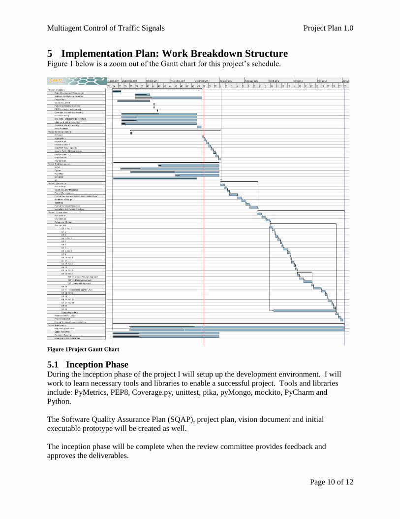
5 Implementation Plan: Work Breakdown Structure Figure 1 below is a zoom out of the Gantt chart for this project’s schedule.
Figure 1Project Gantt Chart
5.1 Inception Phase During the inception phase of the project I will setup up the development environment. I will
work to learn necessary tools and libraries to enable a successful project. Tools and libraries
include: PyMetrics, PEP8, Coverage.py, unittest, pika, pyMongo, mockito, PyCharm and
Python.
The Software Quality Assurance Plan (SQAP), project plan, vision document and initial
executable prototype will be created as well.
The inception phase will be complete when the review committee provides feedback and
approves the deliverables.
Multiagent Control of Traffic Signals Project Plan 1.0
Page 11 of 12
5.2 Project Spike Explorations Since I am dealing with many new tools and libraries in this project I have included a phase for
project spike explorations. These explorations are mini-projects that can be included as small
proof of concept demonstrations. Each spike is intended to investigate how to do a task that
relates to system use cases or underlying functionality. For instance there are explorations
planned on how to use RabbitMQ for agent communication. In addition there are numerous
explorations on how to work with TraCI and SUMO to configure networks, simulate traffic, read
network metrics, read and create traffic sensors and read and control traffic light signals.
This phase will be complete when the spike explorations have been done. There will be code,
notes and potentially small demonstrations delivered. The demonstrations will likely take the
form of an online video for review by the major professor.
5.3 Project Risk Management The risk management section is also concerned with mitigating risk related to the use of new
tools. During this phase I will spend time becoming acquainted with: SUMO, Python,
RabbitMQ, MongoDB and the git distributed version control system. This phase can happen in
conjunction with the project spike explorations. To that end, I have already been working on
material in the inception, spike and risk phases.
This phase will likely be completed in conjunction with the spike explorations. However, it is
likely that some areas will still require further exploration. In that case, the phase will be time
boxed. Code and lessons learned here will most likely be shared via blog post linked from
project site.
5.4 Elaboration Phase As part of the elaboration phase I will address any action items from the previous presentation.
Revisions will include updates to the vision document and project plan. A formal requirement
specification will be done for the Metrics Agent Component. The architecture design will be
done in UML. A project test plan will be created to document the testing processing. A
technical inspection checklist will be created and two inspectors will review the project to see
how it complies with the checklist. The inspectors will provide feedback. Finally, an executable
architecture prototype will be created.
The elaboration phase will be complete when the review committee approves the submitted
documents and the prototype application.
5.5 Construction Phase In the construction phase I will address action items from the previous phase. Feedback from the
Formal Technical Inspection Letters will be incorporated or addressed. The letters themselves
will be included as a deliverable.
Final component design work will be done and the final application will be created. The source
code which fulfills SR1-SR23 will be written with supporting unit, integration and acceptance
tests. A User Manual will be created and delivered.
Multiagent Control of Traffic Signals Project Plan 1.0
Page 12 of 12
An evaluation to assess how the project met the requirements set forth in the vision document
will be completed and included.
A project evaluation which reviews the process used to do the project and the accuracy of the
project estimates will be done.
The construction phase will be completed when deliverables have been presented and the
advisory committee approves them.
5.6 Project Maintenance Project maintenance is a phase I included that incorporates background tasks that run throughout
the project. These tasks include: maintaining an engineering notebook, status reporting, research
reading and maintaining a bibliography and references.