Embed Size (px)
Citation preview
Duct Machine – Setup and Configuration A-Z Darren Young – Systems Integration Manager, Southland Industries
MSF6182 Do you have new sheet metal equipment in your shop and want to understand how to make it interface with your Fabrication CAMduct software? In this session, Southland Industries representatives will overview how to tackle this problem. From understanding which post processors to use, how to setup communications, configuring Fabrication CAMduct, and even modifications to controls like Hypertherm and Burny. Arm yourself with all the information you’ll need to help your IT guys who don’t typically understand this aspect of IT. Be prepared to effectively argue against the machine technician who claims it’s your software when their machine doesn’t work as you think it should. All the information you’ve wanted that’s not taught by anybody else anywhere else will be discussed in this session.
LearningObjectivesAt the end of this class, you will be able to:
Understand CNC G-Code
How to determine/troubleshoot post processors (DPL/VPL)
Perform Machine configuration inside CAMduct
Machine configuration on the control including communications
AbouttheSpeaker
A Midwestern transplant now based in Southern California, veteran Autodesk University speaker Darren Young has held a variety of positions over the last 20 years, including CAD and CAM engineer, CAD administrator, and CAD/CAM systems developer. Currently Darren is the systems integration manager for Southland Industries, one of the largest mechanical engineering and construction companies in the United States. Darren manages one of the largest installations of Fabrication software licenses in the world. While Darren's true interest is the automation of manufacturing systems, his experience ranges from lean manufacturing to architecture, and this has led him to projects varying in scope from dress patterns to gas turbine piping. He has founded a consulting and development business, and he has been a technical editor and publication author.
[email protected] (work) [email protected] (personal)
Duct Machine – Setup and Configuration A-Z
2
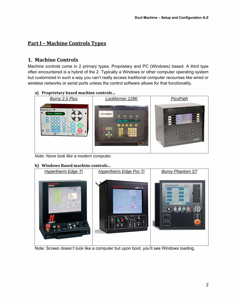
PartI–MachineControlsTypes
1. MachineControlsMachine controls come in 2 primary types, Proprietary and PC (Windows) based. A third type often encountered is a hybrid of the 2. Typically a Windows or other computer operating system but customized in such a way you can’t really access traditional computer recourses like wired or wireless networks or serial ports unless the control software allows for that functionality.
a) Proprietarybasedmachinecontrols… Burny 2.5 Plus
Lockformer 128K PicoPath
Note: None look like a modern computer.
b) WindowsBasedmachinecontrols…Hypertherm Edge TI
Hypertherm Edge Pro TI Burny Phantom ST
Note: Screen doesn’t look like a computer but upon boot, you’ll see Windows loading.
Duct Machine – Setup and Configuration A-Z
3
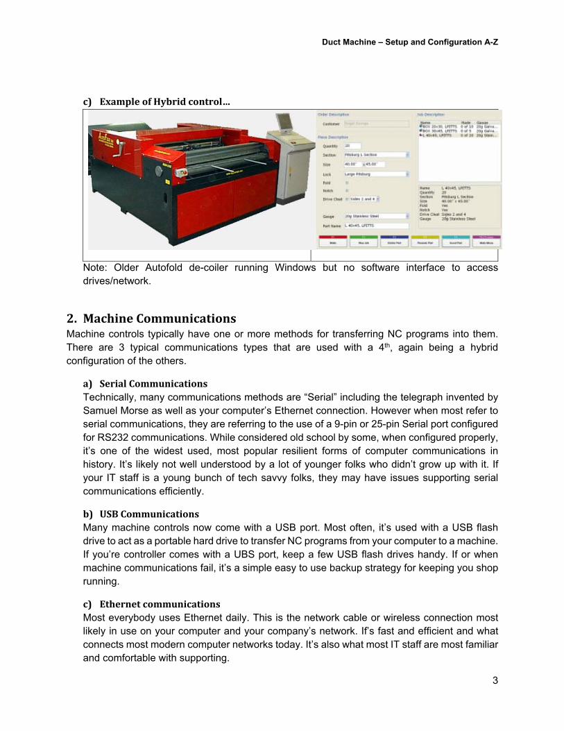
c) ExampleofHybridcontrol…
Note: Older Autofold de-coiler running Windows but no software interface to access drives/network.
2. MachineCommunicationsMachine controls typically have one or more methods for transferring NC programs into them. There are 3 typical communications types that are used with a 4th, again being a hybrid configuration of the others.
a) SerialCommunicationsTechnically, many communications methods are “Serial” including the telegraph invented by Samuel Morse as well as your computer’s Ethernet connection. However when most refer to serial communications, they are referring to the use of a 9-pin or 25-pin Serial port configured for RS232 communications. While considered old school by some, when configured properly, it’s one of the widest used, most popular resilient forms of computer communications in history. It’s likely not well understood by a lot of younger folks who didn’t grow up with it. If your IT staff is a young bunch of tech savvy folks, they may have issues supporting serial communications efficiently.
b) USBCommunicationsMany machine controls now come with a USB port. Most often, it’s used with a USB flash drive to act as a portable hard drive to transfer NC programs from your computer to a machine. If you’re controller comes with a UBS port, keep a few USB flash drives handy. If or when machine communications fail, it’s a simple easy to use backup strategy for keeping you shop running.
c) EthernetcommunicationsMost everybody uses Ethernet daily. This is the network cable or wireless connection most likely in use on your computer and your company’s network. If’s fast and efficient and what connects most modern computer networks today. It’s also what most IT staff are most familiar and comfortable with supporting.
Duct Machine – Setup and Configuration A-Z
4
d) HybridcommunicationsHybrid communications can be all over the place. They involve a mixture of 2 or more communications types and/or hardware components. The specifics of these many of these communications types and hardware will be covered later. Here’s a few of the most common…
Serial w/Short Haul Modem – Used to extend the transmission distance of RS232 or other serial communications. Some Short Haul Modems also offer integrated optical circuits to optically isolate the equipment from your computer so there’s no electrical continuity in the event of a power surge.
Serial w/Fiber Optics – Used when electrical interference from plasma, welding or other industrial equipment interfered with the electrical signals used w/serial communications.
Serial to USB – As modern computers advance, with options like USB plug-and-play mice and keyboards, many newer systems don’t include serial communications ports. They can have an extra expansion card added to connect serial equipment or use specialty USB-to-Serial drives allowing a system with only a USB port to connect and communicate with a serial based machine.
Serial to Ethernet – Same as USB-to-Ethernet, these devices allow serial communications based machines to utilize your existing computer network for connectivity and communications.
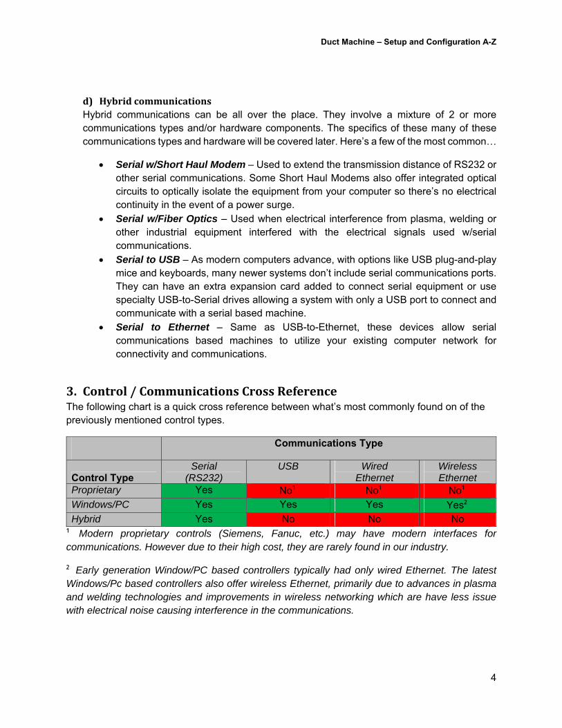
3. Control/CommunicationsCrossReferenceThe following chart is a quick cross reference between what’s most commonly found on of the previously mentioned control types.
Communications Type
Control Type Serial
(RS232) USB Wired
Ethernet Wireless Ethernet
Proprietary Yes No¹ No¹ No¹ Windows/PC Yes Yes Yes Yes² Hybrid Yes No No No
¹ Modern proprietary controls (Siemens, Fanuc, etc.) may have modern interfaces for communications. However due to their high cost, they are rarely found in our industry.
² Early generation Window/PC based controllers typically had only wired Ethernet. The latest Windows/Pc based controllers also offer wireless Ethernet, primarily due to advances in plasma and welding technologies and improvements in wireless networking which are have less issue with electrical noise causing interference in the communications.
Duct Machine – Setup and Configuration A-Z
5
PartII–Software/ProgramOverview
1. MachinePrograms&FilesFor each machine to operate and produce the material you need, it needs to be told what to do. This is done with programming code written specifically for each machine. Each machine and control combination can have its own unique programming style, many of which are very similar but may have its own unique characteristics much like a spoken language can have its own various dialects or regional accents despite being the same language. Others may speak a complete different language all together.
a) NCFiles(Plasma,Router,WaterJet,Laser,etc.)NC Files are programs used to operate Plasma, Router, Water Jet and Laser equipment. Each NC file is written using a special language used to tell the machine what to do and where to go. Instructions tell the machine things like units used, positioning methodology (absolute vs relative), turn cutting tools on and off, as well as positioning instructions. The program nor the machine knows anything about what you are producing, it’s simply cutting various geometric shapes.
The most popular language format is based on G-Code, a “Word Address” based language that uses various alpha-numeric codes to tell the machine where to go and what to do when it gets there. ESSI was another popular format that may be in use today but is far less common. ESSI uses only numeric data and the +/- (plus/minus) operators.
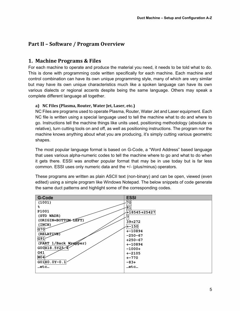
These programs are written as plain ASCII text (non-binary) and can be open, viewed (even edited) using a simple program like Windows Notepad. The below snippets of code generate the same duct patterns and highlight some of the corresponding codes.
G-Code ESSI (1001) % P1001 (STD WADR) (ORIGIN=BOTTOM LEFT) (INCH) G70 (RELATIVE) G91 (PART 1/Back Wrapper) G00X18.5Y25.4 G41 M04 G01X0.0Y-0.1 …etc…
70 81 +18545 +25427 7 39+272 +-150 +-10894 -250-67 +250-67 +-10894 -1000+ +-2105 +-770 -83+ …etc…
Duct Machine – Setup and Configuration A-Z
6
b) DECFiles(Decoiler.CoilLines)DEC files are used to operate and control Decoilers or Coil Lines. They differ in one key way from an NC program which is that they’re not really a program at all, rather a list if what to produce and the specific parameters required to produce those items. Unlike the programs controlled by an NC program which are not aware of what they’re producing other than shapes, a Coil Line is a specialty built machine that produces one thing and one thing only…straight coil line duct.
Similar to NC files which whose contents can vary between machine/control types, DEC files also can vary according to the manufacturer of the coil line. Each manufacturer will have its own specifics for how it wants to list the various pieces of straight duct it’s going to produce and what it needs to define things like seam/connector types as well as stiffener size and position. DEC files are also ASCII text files which can be opened with a plain text editor like Microsoft Notepad.
2. Post‐Processors(VPL/DPL)CAMduct is one program, yet it can create programs for many different machine and control types. Each machine and control combination can have its own language or slight variations of the language and have specific requirements as to how it’s formatted. To solve this problem, we use what’s called a “Post Processor”. A “Post Processor” is nothing more than a specific translator that translates CAMduct’s language into a particular machine/control’s required language.
A list of Post Processors and the versions of software they’re in can be found here…
http://www.xtracad.com/forum/index.php?page=History
a) VPLPostProcessorsEach machine Plasma, Router, Waterjet or Laser machine configured in CAMduct will use a VPL Post Processor. These are what tell the machine setup in CAMduct how to write the code used for that machine. Autodesk places a couple of the most common VPL’s in the root of the CAMduct installation folder but the entire library of VPL’s that ship with the product can be found here…
C:\Program Files\Autodesk\Fabrication 20##\CAMduct\VPLs
b) DPLPostProcessorsEach machine Decoiler machine in CAMduct will use a DPL Post Processor. These are what tell the Decoiler setup in CAMduct how to write the decoil list used for that particular Decoiler. Autodesk places a couple of the most common DPL’s in the root of the CAMduct installation folder but the entire library of DPL’s that ship with the product can be found here…
C:\Program Files\Autodesk\Fabrication 20##\CAMduct\DPLs
Duct Machine – Setup and Configuration A-Z
7
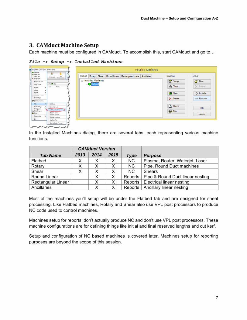
3. CAMductMachineSetupEach machine must be configured in CAMduct. To accomplish this, start CAMduct and go to…
File -> Setup -> Installed Machines
In the Installed Machines dialog, there are several tabs, each representing various machine functions.
Tab Name
CAMduct Version
Type Purpose 2013 2014 2015 Flatbed X X X NC Plasma, Router, Waterjet, Laser Rotary X X X NC Pipe, Round Duct machines Shear X X X NC Shears Round Linear X X Reports Pipe & Round Duct linear nesting Rectangular Linear X X Reports Electrical linear nesting Ancillaries X X Reports Ancillary linear nesting
Most of the machines you’ll setup will be under the Flatbed tab and are designed for sheet processing. Like Flatbed machines, Rotary and Shear also use VPL post processors to produce NC code used to control machines.
Machines setup for reports, don’t actually produce NC and don’t use VPL post processors. These machine configurations are for defining things like initial and final reserved lengths and cut kerf.
Setup and configuration of NC based machines is covered later. Machines setup for reporting purposes are beyond the scope of this session.
Duct Machine – Setup and Configuration A-Z
8
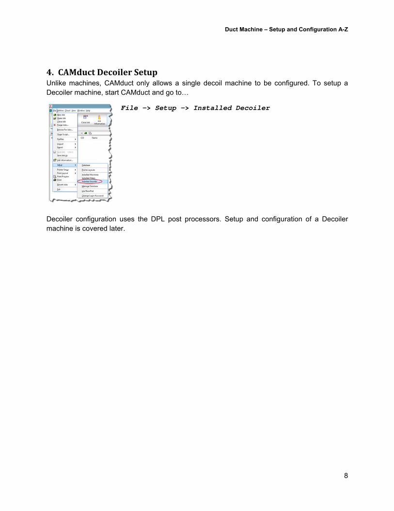
4. CAMductDecoilerSetupUnlike machines, CAMduct only allows a single decoil machine to be configured. To setup a Decoiler machine, start CAMduct and go to…
File -> Setup -> Installed Decoiler
Decoiler configuration uses the DPL post processors. Setup and configuration of a Decoiler machine is covered later.
Duct Machine – Setup and Configuration A-Z
9
PartIII–ProcessOverview
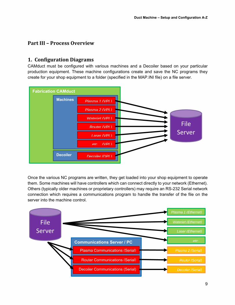
1. ConfigurationDiagramsCAMduct must be configured with various machines and a Decoiler based on your particular production equipment. These machine configurations create and save the NC programs they create for your shop equipment to a folder (specified in the MAP.INI file) on a file server.
Once the various NC programs are written, they get loaded into your shop equipment to operate them. Some machines will have controllers which can connect directly to your network (Ethernet). Others (typically older machines or proprietary controllers) may require an RS-232 Serial network connection which requires a communications program to handle the transfer of the file on the server into the machine control.
Fabrication CAMduct
Machines
Decoiler
Plasma 1 (VPL)
Plasma 2 (VPL)
Waterjet (VPL)
Router (VPL)
Laser (VPL)
Decoiler (DPL)
…etc… (VPL)
File
Server
Plasma 1 (Ethernet)
Plasma 2 (Serial)
Waterjet (Ethernet)
Router (Serial)
Laser (Ethernet)
Decoiler (Serial)
…etc…
File
Server
Communications Server / PC
Plasma Communications (Serial)
Decoiler Communications (Serial)
Router Communications (Serial)
Duct Machine – Setup and Configuration A-Z
10
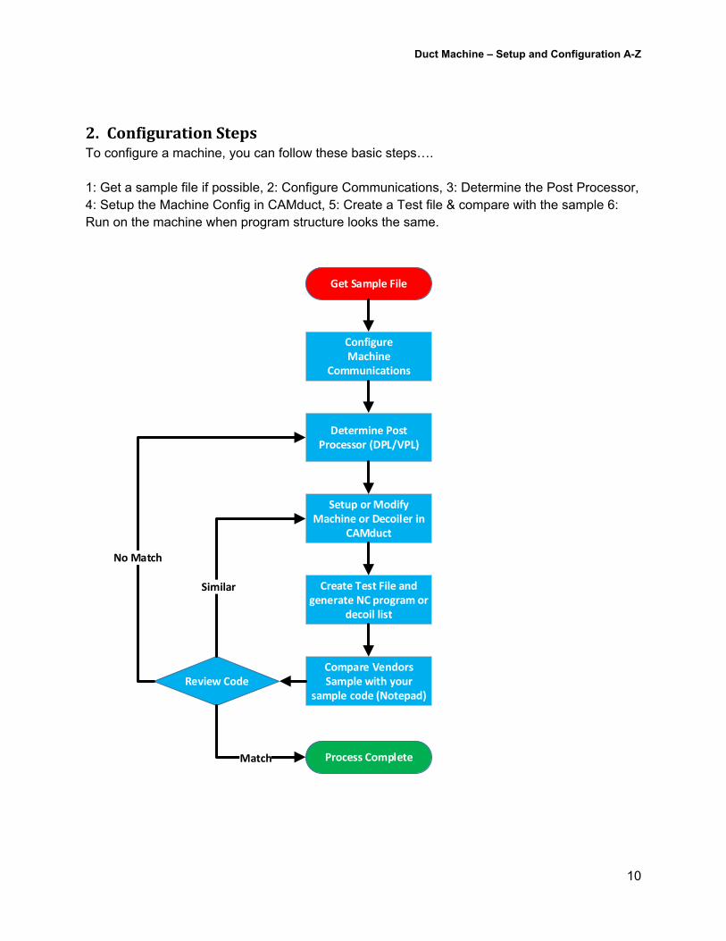
2. ConfigurationStepsTo configure a machine, you can follow these basic steps…. 1: Get a sample file if possible, 2: Configure Communications, 3: Determine the Post Processor, 4: Setup the Machine Config in CAMduct, 5: Create a Test file & compare with the sample 6: Run on the machine when program structure looks the same.
Get Sample File
ConfigureMachine
Communications
Determine Post Processor (DPL/VPL)
Setup or Modify Machine or Decoiler in
CAMduct
Create Test File and generate NC program or
decoil list
Compare Vendors Sample with your
sample code (Notepad)Review Code
No Match
Similar
Process CompleteMatch
Duct Machine – Setup and Configuration A-Z
11
PartIV–ConfigurationDetails
1. ProprietaryControlsEach proprietary control could use any of a variety of communications methods. Some may have only a single option while others may offer various options for getting NC programs into the machine control. The type and number of options will likely vary depending on the age of the controller. Older controllers will likely use RS-232 Serial only, while newer controllers may offer a wider range of options. See the details on the following sections for the specific communications type that your control requires. Often, a proprietary controller will need you to configure its communication type and/or parameters using the interface it provides. Consult the controller’s operations and configuration manuals for details.
2. HybridControlsSimilar to a proprietary control, each controls will allow whatever the control designer and software developer intended. Because a hybrid control is also PC based, for those that are tech savvy, it may (or may not) be possible to make some modifications yourself to allow different types of configurations. For ideas, see some of the details under PC Controls. Consult the control operation and configuration manuals for what configuration needs to be done on the control based on the communication type you need.
3. PCBasedControlsMost modern PC based controls allow for multiple types of communications. This includes everything from USB, Wired and Wireless Ethernet as well as RS-232 Serial communications. Details of those communications types will be covered later however there are several things you can do on the control itself to make your life easier. While the main screen may not offer a way to get back to the Windows interface, simply plug in a keyboard into an open USB port. If you type Ctrl-F4, this should exit the control software. You can also pressing Alt-Tab to activate another Window or press the Windows key to bring up the start menu.
a) NetworkDomainsJoining your machine’s controller to a network domain can make accessing NC files on your network easier. Most IT folks would prefer this approach, perhaps even installing anti-virus programs on the controller. If at all possible, avoid placing your machine control on your network domain. Many controller manufacturers like Hypertherm recommend against it as this can cause network group policies or untested Windows updates to cause issues with your controller’s operation. Controlling machine motion in real time is a very sensitive process. The company that built your machine controller has done extensive testing with it configured as is, avoid putting additional constraints on it.
Duct Machine – Setup and Configuration A-Z
12
b) Usernames&PasswordsMost PC based controllers will have a default username and password for you to use if they are not configured to logon automatically upon start. As long as you don’t join your controller to your network domain, this is the best option for use.
If you want to have a common username/password for all your shop equipment, you may be able to get the machine builder to walk you through changing it. The technician installing your machine may or may not have the skills to do the work, as they’re often very skilled in the physical installation but light on computer skills.
Some controllers, changing the username and password is easy while others may require jumping through more hoops. Whether you use the controller’s defaults or change them to something you specify, keep this information documented well.
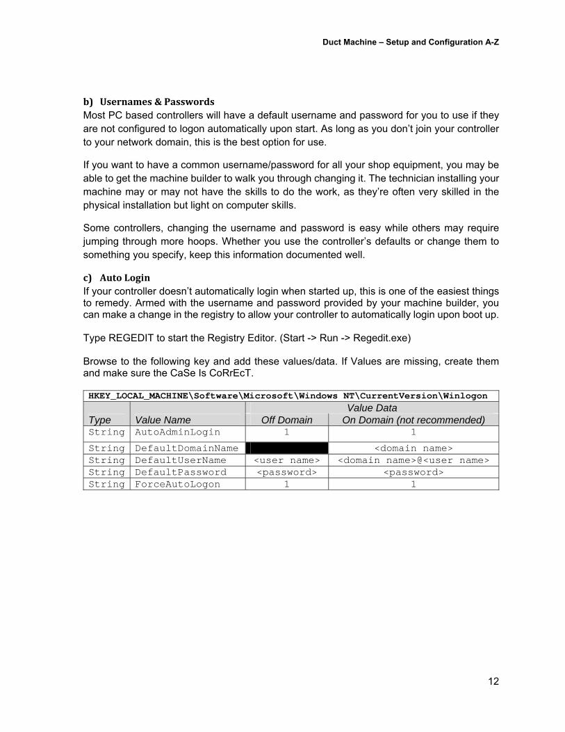
c) AutoLoginIf your controller doesn’t automatically login when started up, this is one of the easiest things to remedy. Armed with the username and password provided by your machine builder, you can make a change in the registry to allow your controller to automatically login upon boot up. Type REGEDIT to start the Registry Editor. (Start -> Run -> Regedit.exe) Browse to the following key and add these values/data. If Values are missing, create them and make sure the CaSe Is CoRrEcT. HKEY_LOCAL_MACHINE\Software\Microsoft\Windows NT\CurrentVersion\Winlogon
Type Value Name Value Data
Off Domain On Domain (not recommended) String AutoAdminLogin 1 1
String DefaultDomainName <domain name> String DefaultUserName <user name> <domain name>@<user name> String DefaultPassword <password> <password> String ForceAutoLogon 1 1
Duct Machine – Setup and Configuration A-Z
13
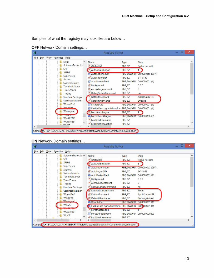
Samples of what the registry may look like are below… OFF Network Domain settings…
ON Network Domain settings…
Duct Machine – Setup and Configuration A-Z
14
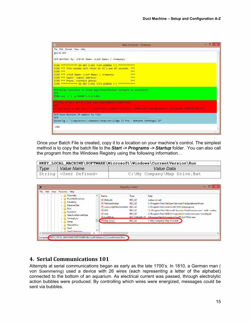
d) NetworkAccess&DriveMappingWhile adding your controller to your network domain isn’t recommended, it does make accessing network resources easier. However this can be easily remedied with some simple batch files. To start, you’ll need a username/password for your network that will allow access to the location you store your NC files. It’s recommended that a generic user account be created as opposed to using one from a user. Username should have only limited permissions to only the areas where needed to ensure security. A password can then be set to not expire while maintaining security as it only has limited access to the folder were your NC files reside. This ensures that your machine communications are not rendered broken due to passwords expiring or users leaving the company. As with the logon information provided with your control, this account information should be documented. Other considerations for a batch file….
Operator Message (see Yellow section below). When the batch file runs, it may display a DOS windows in on the screen. It’s recommended to display a user friendly message to the operator so they know what to expect.
Delayed Execution (see Green section below) Some machine control software consumes a lot of system resources when it launches. This can cause things like drive mapping to fail if those attempt to occur before networking resources are fully initialized. You can use the DOS “Ping” command to a bogus IP address to introduce a delay. In this sample, a 45 second delay is specified in milliseconds (45000).
Map Network Drive (see Red section below) Most machine controls will be able to access a mapped drive. You can use the DOS batch file to map a drive letter using the network username/password you had created for access to NC files on your server.
Controller’s Network Address (see Blue section below) If you know your machine’s network IP address, it can help an IT savvy person access the control remotely. Whether it’s accessing the disk remotely or performing a screen share, your machine control’s network address may be subject to change. Sending the IP address to a file on your network records the machine’s current IP address each time it’s turned on.
Duct Machine – Setup and Configuration A-Z
15
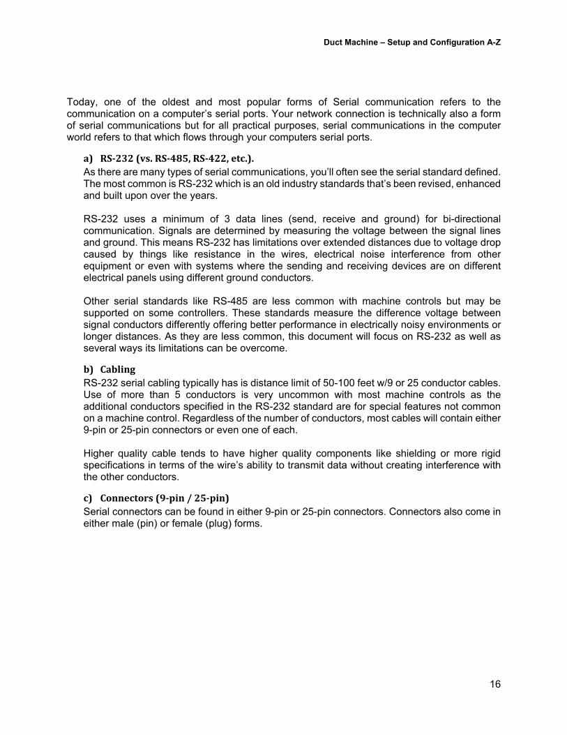
Once your Batch File is created, copy it to a location on your machine’s control. The simplest method is to copy the batch file to the Start -> Programs -> Startup folder. You can also call the program from the Windows Registry using the following information… HKEY_LOCAL_MACHINE\SOFTWARE\Microsoft\Windows\CurrentVersion\Run Type Value Name Value Data String <User Defined> C:\My Company\Map Drive.Bat
4. SerialCommunications101Attempts at serial communications began as early as the late 1700’s. In 1810, a German man ( von Soemmering) used a device with 26 wires (each representing a letter of the alphabet) connected to the bottom of an aquarium. As electrical current was passed, through electrolytic action bubbles were produced. By controlling which wires were energized, messages could be sent via bubbles.
Duct Machine – Setup and Configuration A-Z
16
Today, one of the oldest and most popular forms of Serial communication refers to the communication on a computer’s serial ports. Your network connection is technically also a form of serial communications but for all practical purposes, serial communications in the computer world refers to that which flows through your computers serial ports.
a) RS‐232(vs.RS‐485,RS‐422,etc.).As there are many types of serial communications, you’ll often see the serial standard defined. The most common is RS-232 which is an old industry standards that’s been revised, enhanced and built upon over the years. RS-232 uses a minimum of 3 data lines (send, receive and ground) for bi-directional communication. Signals are determined by measuring the voltage between the signal lines and ground. This means RS-232 has limitations over extended distances due to voltage drop caused by things like resistance in the wires, electrical noise interference from other equipment or even with systems where the sending and receiving devices are on different electrical panels using different ground conductors. Other serial standards like RS-485 are less common with machine controls but may be supported on some controllers. These standards measure the difference voltage between signal conductors differently offering better performance in electrically noisy environments or longer distances. As they are less common, this document will focus on RS-232 as well as several ways its limitations can be overcome.
b) CablingRS-232 serial cabling typically has is distance limit of 50-100 feet w/9 or 25 conductor cables. Use of more than 5 conductors is very uncommon with most machine controls as the additional conductors specified in the RS-232 standard are for special features not common on a machine control. Regardless of the number of conductors, most cables will contain either 9-pin or 25-pin connectors or even one of each. Higher quality cable tends to have higher quality components like shielding or more rigid specifications in terms of the wire’s ability to transmit data without creating interference with the other conductors.
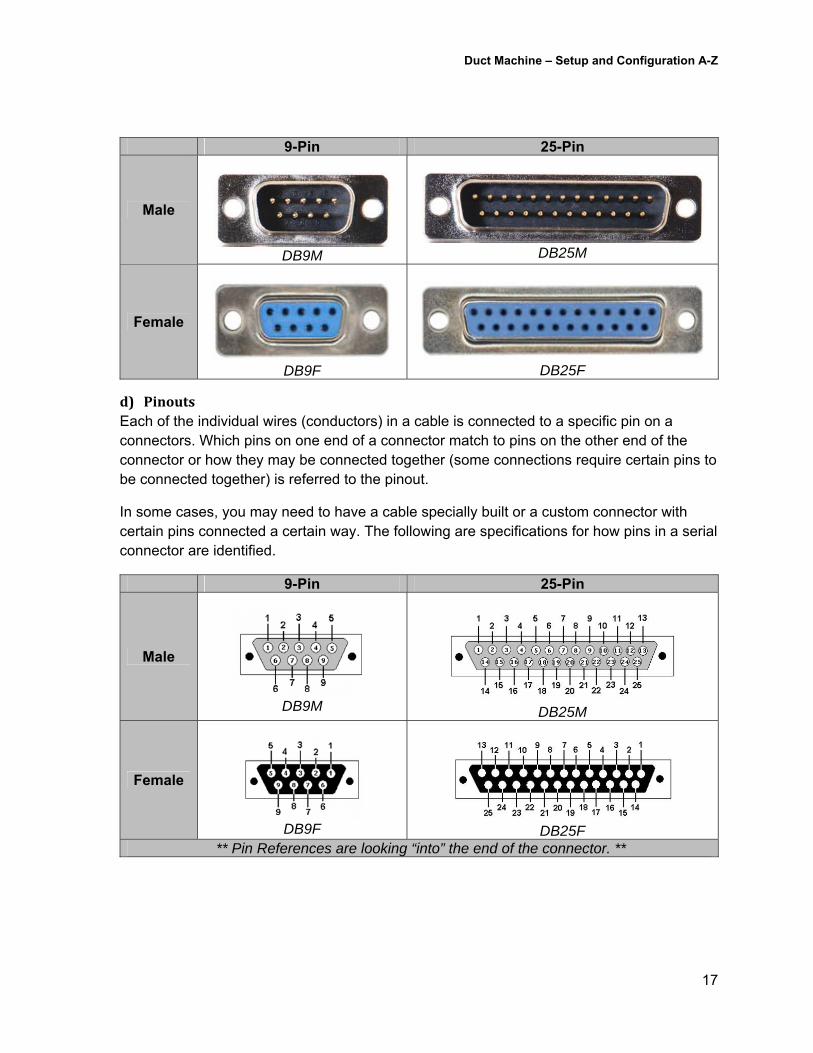
c) Connectors(9‐pin/25‐pin)Serial connectors can be found in either 9-pin or 25-pin connectors. Connectors also come in either male (pin) or female (plug) forms.
Duct Machine – Setup and Configuration A-Z
17
9-Pin 25-Pin
Male
DB9M
DB25M
Female
DB9F
DB25F
d) PinoutsEach of the individual wires (conductors) in a cable is connected to a specific pin on a connectors. Which pins on one end of a connector match to pins on the other end of the connector or how they may be connected together (some connections require certain pins to be connected together) is referred to the pinout.
In some cases, you may need to have a cable specially built or a custom connector with certain pins connected a certain way. The following are specifications for how pins in a serial connector are identified.
9-Pin 25-Pin
Male
DB9M
DB25M
Female
DB9F
DB25F
** Pin References are looking “into” the end of the connector. **
Duct Machine – Setup and Configuration A-Z
18
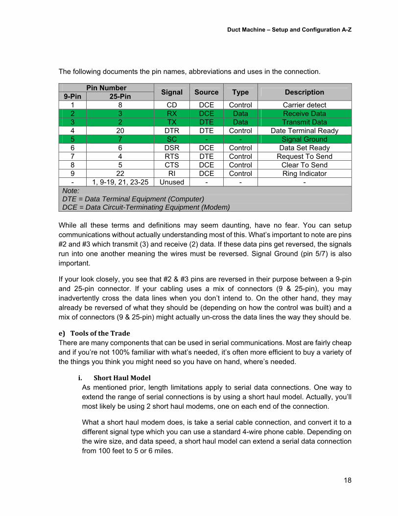
The following documents the pin names, abbreviations and uses in the connection.
Pin Number Signal Source Type Description
9-Pin 25-Pin 1 8 CD DCE Control Carrier detect 2 3 RX DCE Data Receive Data 3 2 TX DTE Data Transmit Data 4 20 DTR DTE Control Date Terminal Ready 5 7 SC - - Signal Ground 6 6 DSR DCE Control Data Set Ready 7 4 RTS DTE Control Request To Send 8 5 CTS DCE Control Clear To Send 9 22 RI DCE Control Ring Indicator - 1, 9-19, 21, 23-25 Unused - - -
Note: DTE = Data Terminal Equipment (Computer) DCE = Data Circuit-Terminating Equipment (Modem)
While all these terms and definitions may seem daunting, have no fear. You can setup communications without actually understanding most of this. What’s important to note are pins #2 and #3 which transmit (3) and receive (2) data. If these data pins get reversed, the signals run into one another meaning the wires must be reversed. Signal Ground (pin 5/7) is also important.
If your look closely, you see that #2 & #3 pins are reversed in their purpose between a 9-pin and 25-pin connector. If your cabling uses a mix of connectors (9 & 25-pin), you may inadvertently cross the data lines when you don’t intend to. On the other hand, they may already be reversed of what they should be (depending on how the control was built) and a mix of connectors (9 & 25-pin) might actually un-cross the data lines the way they should be.
e) ToolsoftheTradeThere are many components that can be used in serial communications. Most are fairly cheap and if you’re not 100% familiar with what’s needed, it’s often more efficient to buy a variety of the things you think you might need so you have on hand, where’s needed.
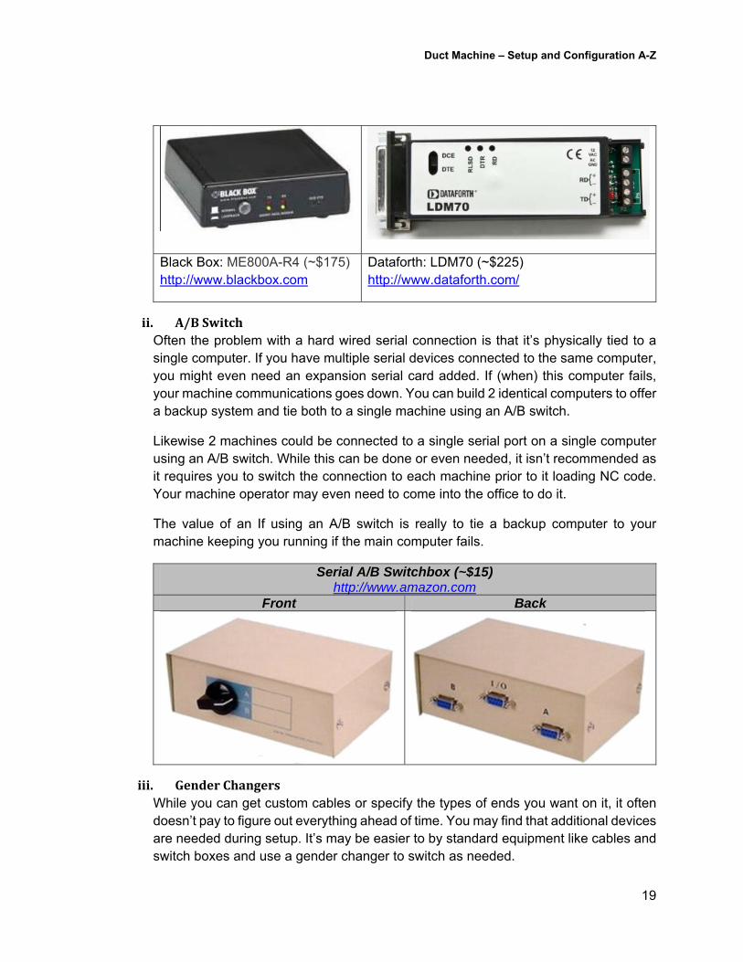
i. ShortHaulModelAs mentioned prior, length limitations apply to serial data connections. One way to extend the range of serial connections is by using a short haul model. Actually, you’ll most likely be using 2 short haul modems, one on each end of the connection.
What a short haul modem does, is take a serial cable connection, and convert it to a different signal type which you can use a standard 4-wire phone cable. Depending on the wire size, and data speed, a short haul model can extend a serial data connection from 100 feet to 5 or 6 miles.
Duct Machine – Setup and Configuration A-Z
19
Black Box: ME800A-R4 (~$175) http://www.blackbox.com
Dataforth: LDM70 (~$225) http://www.dataforth.com/
ii. A/BSwitchOften the problem with a hard wired serial connection is that it’s physically tied to a single computer. If you have multiple serial devices connected to the same computer, you might even need an expansion serial card added. If (when) this computer fails, your machine communications goes down. You can build 2 identical computers to offer a backup system and tie both to a single machine using an A/B switch.
Likewise 2 machines could be connected to a single serial port on a single computer using an A/B switch. While this can be done or even needed, it isn’t recommended as it requires you to switch the connection to each machine prior to it loading NC code. Your machine operator may even need to come into the office to do it.
The value of an If using an A/B switch is really to tie a backup computer to your machine keeping you running if the main computer fails.
Serial A/B Switchbox (~$15) http://www.amazon.com
Front Back
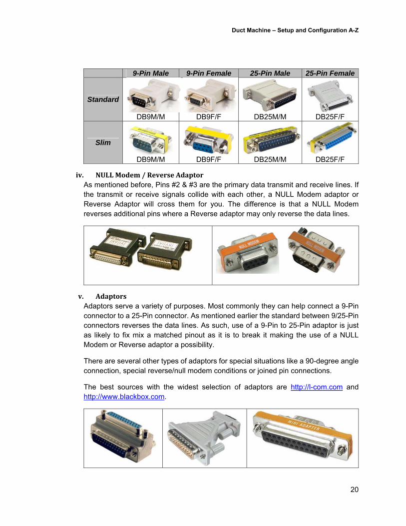
iii. GenderChangersWhile you can get custom cables or specify the types of ends you want on it, it often doesn’t pay to figure out everything ahead of time. You may find that additional devices are needed during setup. It’s may be easier to by standard equipment like cables and switch boxes and use a gender changer to switch as needed.
Duct Machine – Setup and Configuration A-Z
20
9-Pin Male 9-Pin Female 25-Pin Male 25-Pin Female
Standard
DB9M/M DB9F/F
DB25M/M
DB25F/F
Slim
DB9M/M DB9F/F DB25M/M DB25F/F
iv. NULLModem/ReverseAdaptorAs mentioned before, Pins #2 & #3 are the primary data transmit and receive lines. If the transmit or receive signals collide with each other, a NULL Modem adaptor or Reverse Adaptor will cross them for you. The difference is that a NULL Modem reverses additional pins where a Reverse adaptor may only reverse the data lines.
v. AdaptorsAdaptors serve a variety of purposes. Most commonly they can help connect a 9-Pin connector to a 25-Pin connector. As mentioned earlier the standard between 9/25-Pin connectors reverses the data lines. As such, use of a 9-Pin to 25-Pin adaptor is just as likely to fix mix a matched pinout as it is to break it making the use of a NULL Modem or Reverse adaptor a possibility.
There are several other types of adaptors for special situations like a 90-degree angle connection, special reverse/null modem conditions or joined pin connections.
The best sources with the widest selection of adaptors are http://l-com.com and http://www.blackbox.com.
Duct Machine – Setup and Configuration A-Z
21
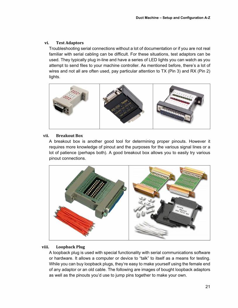
vi. TestAdaptorsTroubleshooting serial connections without a lot of documentation or if you are not real familiar with serial cabling can be difficult. For these situations, test adaptors can be used. They typically plug in-line and have a series of LED lights you can watch as you attempt to send files to your machine controller. As mentioned before, there’s a lot of wires and not all are often used, pay particular attention to TX (Pin 3) and RX (Pin 2) lights.
vii. BreakoutBoxA breakout box is another good tool for determining proper pinouts. However it requires more knowledge of pinout and the purposes for the various signal lines or a lot of patience (perhaps both). A good breakout box allows you to easily try various pinout connections.
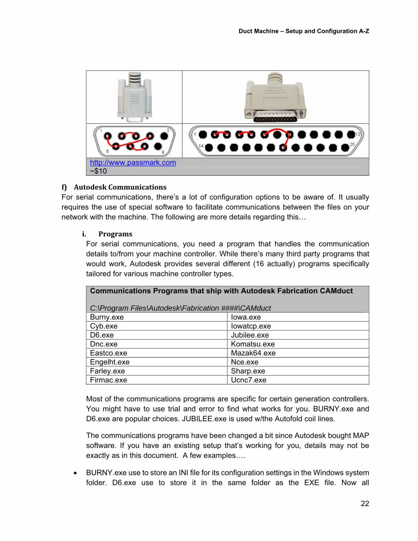
viii. LoopbackPlugA loopback plug is used with special functionality with serial communications software or hardware. It allows a computer or device to “talk” to itself as a means for testing. While you can buy loopback plugs, they’re easy to make yourself using the female end of any adaptor or an old cable. The following are images of bought loopback adaptors as well as the pinouts you’d use to jump pins together to make your own.
Duct Machine – Setup and Configuration A-Z
22
http://www.passmark.com ~$10
f) AutodeskCommunicationsFor serial communications, there’s a lot of configuration options to be aware of. It usually requires the use of special software to facilitate communications between the files on your network with the machine. The following are more details regarding this…
i. ProgramsFor serial communications, you need a program that handles the communication details to/from your machine controller. While there’s many third party programs that would work, Autodesk provides several different (16 actually) programs specifically tailored for various machine controller types.
Communications Programs that ship with Autodesk Fabrication CAMduct C:\Program Files\Autodesk\Fabrication ####\CAMduct Burny.exe Iowa.exe Cyb.exe Iowatcp.exe D6.exe Jubilee.exe Dnc.exe Komatsu.exe Eastco.exe Mazak64.exe Engelht.exe Nce.exe Farley.exe Sharp.exe Firmac.exe Ucnc7.exe
Most of the communications programs are specific for certain generation controllers. You might have to use trial and error to find what works for you. BURNY.exe and D6.exe are popular choices. JUBILEE.exe is used w/the Autofold coil lines.
The communications programs have been changed a bit since Autodesk bought MAP software. If you have an existing setup that’s working for you, details may not be exactly as in this document. A few examples….
BURNY.exe use to store an INI file for its configuration settings in the Windows system folder. D6.exe use to store it in the same folder as the EXE file. Now all
Duct Machine – Setup and Configuration A-Z
23
communications programs store their settings in the same folder as the MAP.INI file.
2013 Communications programs also were still 32-bit programs even when installing on a 64-bit operating system. As such, the “cloud” functionality added to the software would produce an error on the 64-bit systems when the 32-bit communications program tried to load the 64-it “Cloud” libraries. To fix that, you’d simply rename the “Cloud” folder in “C:\Program Files\Autodesk\Fabrication XXXX\<product>\Cloud” to something else so the software can’t load the incompatible DLL’s. You’d also need to rename it for all products as sometimes one product would reference the cloud folder of another product.
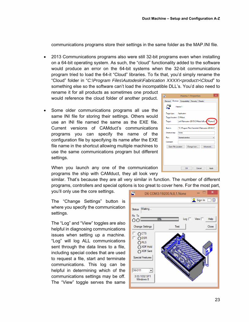
Some older communications programs all use the same INI file for storing their settings. Others would use an INI file named the same as the EXE file. Current versions of CAMduct’s communications programs you can specify the name of the configuration file by specifying its name after the EXE file name in the shortcut allowing multiple machines to use the same communications program but different settings.
When you launch any one of the communication programs the ship with CAMduct, they all look very similar. That’s because they are all very similar in function. The number of different programs, controllers and special options is too great to cover here. For the most part, you’ll only use the core settings.
The “Change Settings” button is where you specify the communication settings.
The “Log” and “View” toggles are also helpful in diagnosing communications issues when setting up a machine. “Log” will log ALL communications sent through the data lines to a file, including special codes that are used to request a file, start and terminate communications. This log can be helpful in determining which of the communications settings may be off. The “View” toggle serves the same
Duct Machine – Setup and Configuration A-Z
24
purpose only instead of sending the data to a file, it displays it in the dialog where the machine image is instead.
Other buttons, dropdowns or Special Features vary by communications program. You may need to do a bit of trial and error if your machine needs them but start with the basics and rule out problems there first. The CTS & DSR toggles only will come into play if you are using hardware handshaking. They define if your system should be configured as the sending or receiving system so it knows which direction the handshaking signals should be sent. The controller you’re connecting to will determine if this is required.
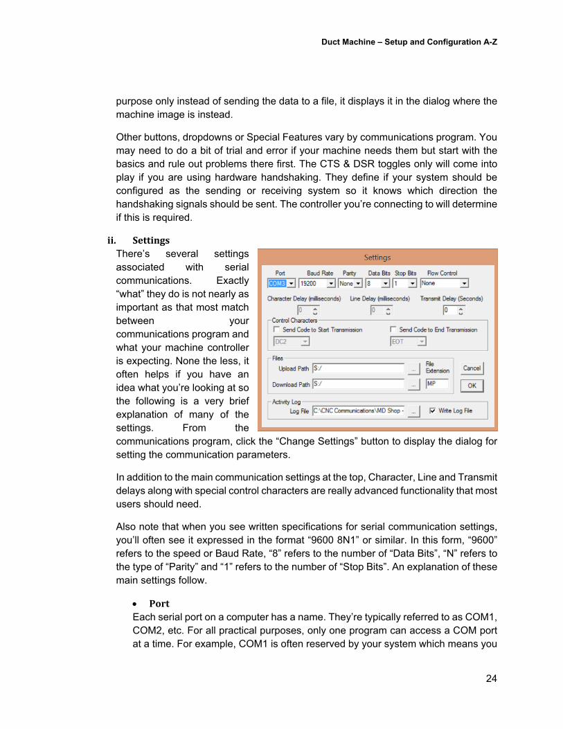
ii. SettingsThere’s several settings associated with serial communications. Exactly “what” they do is not nearly as important as that most match between your communications program and what your machine controller is expecting. None the less, it often helps if you have an idea what you’re looking at so the following is a very brief explanation of many of the settings. From the communications program, click the “Change Settings” button to display the dialog for setting the communication parameters.
In addition to the main communication settings at the top, Character, Line and Transmit delays along with special control characters are really advanced functionality that most users should need.
Also note that when you see written specifications for serial communication settings, you’ll often see it expressed in the format “9600 8N1” or similar. In this form, “9600” refers to the speed or Baud Rate, “8” refers to the number of “Data Bits”, “N” refers to the type of “Parity” and “1” refers to the number of “Stop Bits”. An explanation of these main settings follow.
PortEach serial port on a computer has a name. They’re typically referred to as COM1, COM2, etc. For all practical purposes, only one program can access a COM port at a time. For example, COM1 is often reserved by your system which means you

Duct Machine – Setup and Configuration A-Z
25
much use COM2, COM3, etc. If you run out of COM ports, you may need to have an expansion card added to your system.
The COM Port is one setting that does NOT hate to match what you’re connecting to. It simply tells the communications program which port to pull data from on your computer. The Controller handles this function on the other end.
BaudRateSerial communications use electrical signals to send data. Baud rate refers to the number of symbols per second that can be sent. In a nutshell, it’s the speed at which the data is transmitted. The further the serial communication, the less speed may be supported. This communications rate needs to match what is set on your controller.
Common Baud Rates are….110, 150, 300, 600, 1200, 2400, 4800, 9600, 19200, 38400, 57600, & 115200. The minimum you typically see on older systems is 2400, 9600 is fairly common. Newer systems can typically go much faster. If you think all your settings are correct and communications still fail, try setting a lower Baud rate like 2400 on your controller and communications software.
If it works it’s likely too fast a speed is suffering too much signal loss or your controller just can’t keep up. Once working, you can try to bump it up (remember, on both the controller and your Communications software) to get a faster transfer speed.
DataBitsBits are the smallest measure of data in computers. Bit is short Binary Digit. When serial communications occur, each character is sent in either 7 or 8 bits of data coordinated by a start bit and an optional stop bit (see next section).
ParityAs data is sent through serial communication, there’s an extra bit of data used as an error checking algorithm. This extra bit of data is referred to as Parity. Varity values in the communications software much match that of your machine control.
Parity values can be….Odd, Even, None, Mark and Space. These are often just referenced by letter….O,E,N,M and S.
StopBitsStop bits are extra data that follow the data bits and any parity data. They mark the end of transmission of a piece of data such as a byte or character.
FlowControl/HandshakingIf you work working with a person picking apples, you might be in tree, tossing apples to the person below. They catch and place them in a bucket. All is well until

Duct Machine – Setup and Configuration A-Z
26
the bucket is full which requires the person on the ground to empty it or get a new one. If the person in the tree doesn’t know this is happening, they keep throwing apples and they hit the ground and get ruined.
Serial communications flow control serves the same purpose. The sending and receiving systems use flow control or handshaking as a way to tell the other system when it’s buffer can hold more information.
Settings for flow control are XON/XOFF (software flow control), Hardware, Combined or None. Hardware flow control requires additional signal lines which may make cabling, connectors and such a more difficult task. Software flow control (XON/XOFF) on the other hand uses the standard data lines but as a result, does reduce the bandwidth of the communications however it’s usually insignificant to matter.
The faster the serial communication setting, the more important flow control becomes. This is especially true in older systems.
iii. TestingWhile you might be tempted to redo your data connections when you click the “Test” button from the communication program and see that it fails, this isn’t doing what it appears. For the test button to work, you need to use a serial loopback. Your machine control may have a mode that enables this, or the Black Box short haul modems shown earlier also have an option to create a “loopback”. This is where the communications are configured to talk to itself for testing communication.
If you’ve needed a lot of serial adaptors and such, disconnect the cable on the machine end and add a loopback plug. Now click the test button. If all the cabling and pins are configured properly, it should succeed.
iv. FilesandLogsWithin the “Change Settings” dialog, you’ll also see where you can tell the communications to read (or write if supported by your controller) the NC files from on your network. This can be a local drive or network specified via drive letter or UNC pathing.
Lastly, you can also specify a log file and location. This differs from the Log toggle on the main communication dialog which logs all the data sent and received. Instead, this log records which programs have been sent or received during communications. If you wanted to see which NC programs were sent, this is where that location would be stored.
Duct Machine – Setup and Configuration A-Z
27
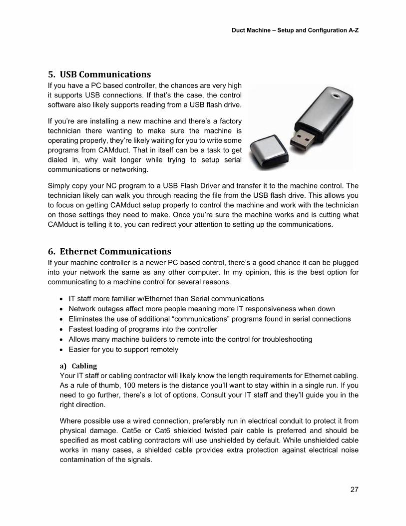
5. USBCommunicationsIf you have a PC based controller, the chances are very high it supports USB connections. If that’s the case, the control software also likely supports reading from a USB flash drive.
If you’re are installing a new machine and there’s a factory technician there wanting to make sure the machine is operating properly, they’re likely waiting for you to write some programs from CAMduct. That in itself can be a task to get dialed in, why wait longer while trying to setup serial communications or networking.
Simply copy your NC program to a USB Flash Driver and transfer it to the machine control. The technician likely can walk you through reading the file from the USB flash drive. This allows you to focus on getting CAMduct setup properly to control the machine and work with the technician on those settings they need to make. Once you’re sure the machine works and is cutting what CAMduct is telling it to, you can redirect your attention to setting up the communications.
6. EthernetCommunicationsIf your machine controller is a newer PC based control, there’s a good chance it can be plugged into your network the same as any other computer. In my opinion, this is the best option for communicating to a machine control for several reasons.
IT staff more familiar w/Ethernet than Serial communications Network outages affect more people meaning more IT responsiveness when down Eliminates the use of additional “communications” programs found in serial connections Fastest loading of programs into the controller Allows many machine builders to remote into the control for troubleshooting Easier for you to support remotely
a) CablingYour IT staff or cabling contractor will likely know the length requirements for Ethernet cabling. As a rule of thumb, 100 meters is the distance you’ll want to stay within in a single run. If you need to go further, there’s a lot of options. Consult your IT staff and they’ll guide you in the right direction.
Where possible use a wired connection, preferably run in electrical conduit to protect it from physical damage. Cat5e or Cat6 shielded twisted pair cable is preferred and should be specified as most cabling contractors will use unshielded by default. While unshielded cable works in many cases, a shielded cable provides extra protection against electrical noise contamination of the signals.
Duct Machine – Setup and Configuration A-Z
28
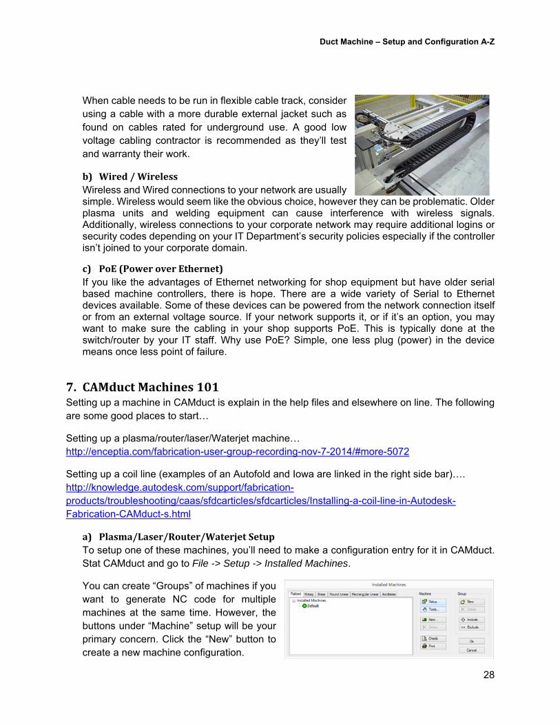
When cable needs to be run in flexible cable track, consider using a cable with a more durable external jacket such as found on cables rated for underground use. A good low voltage cabling contractor is recommended as they’ll test and warranty their work.
b) Wired/WirelessWireless and Wired connections to your network are usually simple. Wireless would seem like the obvious choice, however they can be problematic. Older plasma units and welding equipment can cause interference with wireless signals. Additionally, wireless connections to your corporate network may require additional logins or security codes depending on your IT Department’s security policies especially if the controller isn’t joined to your corporate domain.
c) PoE(PoweroverEthernet)If you like the advantages of Ethernet networking for shop equipment but have older serial based machine controllers, there is hope. There are a wide variety of Serial to Ethernet devices available. Some of these devices can be powered from the network connection itself or from an external voltage source. If your network supports it, or if it’s an option, you may want to make sure the cabling in your shop supports PoE. This is typically done at the switch/router by your IT staff. Why use PoE? Simple, one less plug (power) in the device means once less point of failure.
7. CAMductMachines101Setting up a machine in CAMduct is explain in the help files and elsewhere on line. The following are some good places to start…
Setting up a plasma/router/laser/Waterjet machine… http://enceptia.com/fabrication-user-group-recording-nov-7-2014/#more-5072
Setting up a coil line (examples of an Autofold and Iowa are linked in the right side bar)…. http://knowledge.autodesk.com/support/fabrication-products/troubleshooting/caas/sfdcarticles/sfdcarticles/Installing-a-coil-line-in-Autodesk-Fabrication-CAMduct-s.html
a) Plasma/Laser/Router/WaterjetSetupTo setup one of these machines, you’ll need to make a configuration entry for it in CAMduct. Stat CAMduct and go to File -> Setup -> Installed Machines.
You can create “Groups” of machines if you want to generate NC code for multiple machines at the same time. However, the buttons under “Machine” setup will be your primary concern. Click the “New” button to create a new machine configuration.
Duct Machine – Setup and Configuration A-Z
29
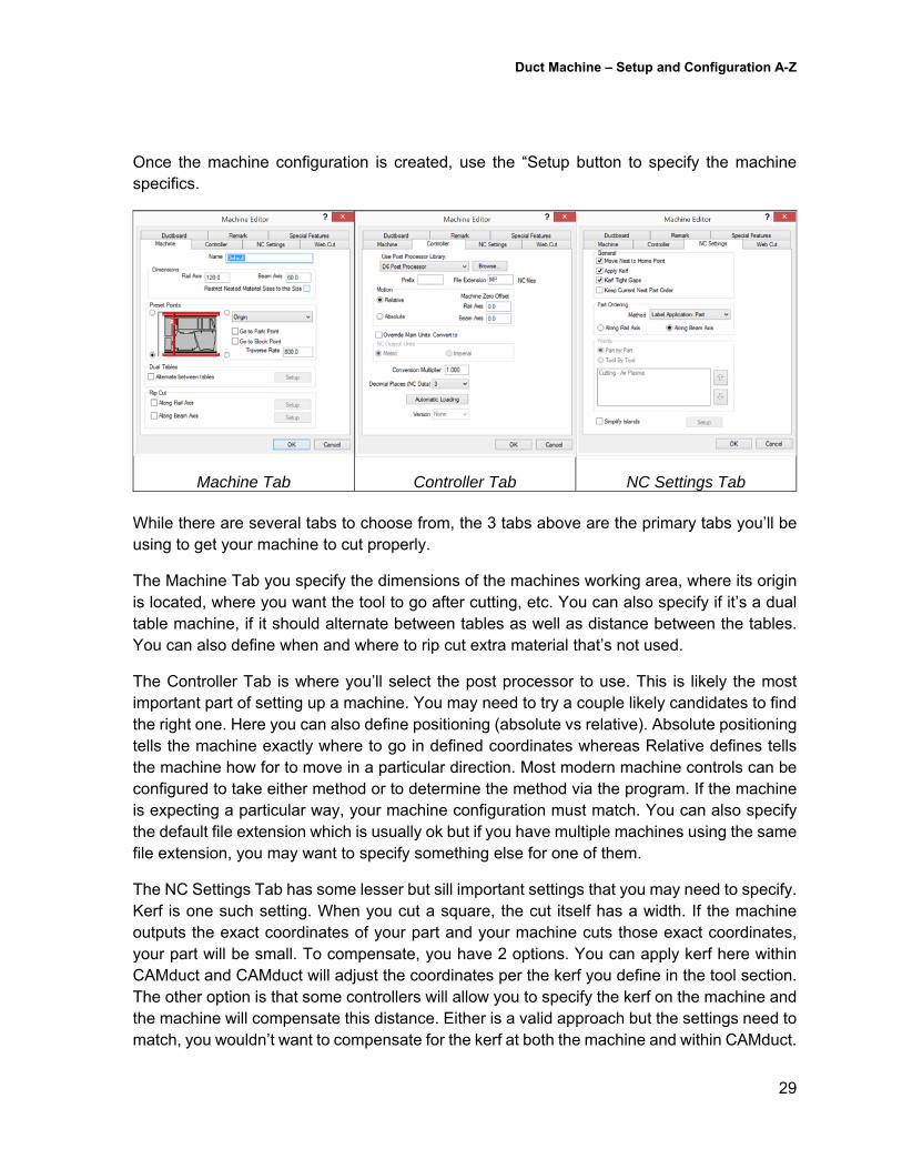
Once the machine configuration is created, use the “Setup button to specify the machine specifics.
Machine Tab Controller Tab
NC Settings Tab While there are several tabs to choose from, the 3 tabs above are the primary tabs you’ll be using to get your machine to cut properly.
The Machine Tab you specify the dimensions of the machines working area, where its origin is located, where you want the tool to go after cutting, etc. You can also specify if it’s a dual table machine, if it should alternate between tables as well as distance between the tables. You can also define when and where to rip cut extra material that’s not used.
The Controller Tab is where you’ll select the post processor to use. This is likely the most important part of setting up a machine. You may need to try a couple likely candidates to find the right one. Here you can also define positioning (absolute vs relative). Absolute positioning tells the machine exactly where to go in defined coordinates whereas Relative defines tells the machine how for to move in a particular direction. Most modern machine controls can be configured to take either method or to determine the method via the program. If the machine is expecting a particular way, your machine configuration must match. You can also specify the default file extension which is usually ok but if you have multiple machines using the same file extension, you may want to specify something else for one of them.
The NC Settings Tab has some lesser but sill important settings that you may need to specify. Kerf is one such setting. When you cut a square, the cut itself has a width. If the machine outputs the exact coordinates of your part and your machine cuts those exact coordinates, your part will be small. To compensate, you have 2 options. You can apply kerf here within CAMduct and CAMduct will adjust the coordinates per the kerf you define in the tool section. The other option is that some controllers will allow you to specify the kerf on the machine and the machine will compensate this distance. Either is a valid approach but the settings need to match, you wouldn’t want to compensate for the kerf at both the machine and within CAMduct.
Duct Machine – Setup and Configuration A-Z
30
Some of these settings may be the most difficult things to setup when getting a new machine. Often the factory technician isn’t versed in the software and when you ask specifics, they’ll tell you the machine will do whatever you want it to (can be configured on the machine) or tell you it’s up to you to do it in the software. Often, they just don’t know. Sometimes you’ll just have to output code to the machine and see what works and what doesn’t and adjust on the machine or CAMduct as best you can.
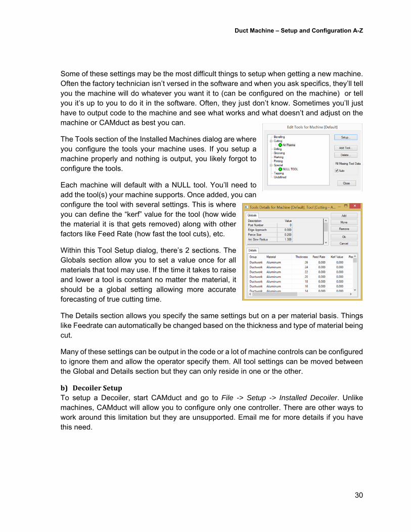
The Tools section of the Installed Machines dialog are where you configure the tools your machine uses. If you setup a machine properly and nothing is output, you likely forgot to configure the tools.
Each machine will default with a NULL tool. You’ll need to add the tool(s) your machine supports. Once added, you can configure the tool with several settings. This is where you can define the “kerf” value for the tool (how wide the material it is that gets removed) along with other factors like Feed Rate (how fast the tool cuts), etc.
Within this Tool Setup dialog, there’s 2 sections. The Globals section allow you to set a value once for all materials that tool may use. If the time it takes to raise and lower a tool is constant no matter the material, it should be a global setting allowing more accurate forecasting of true cutting time.
The Details section allows you specify the same settings but on a per material basis. Things like Feedrate can automatically be changed based on the thickness and type of material being cut.
Many of these settings can be output in the code or a lot of machine controls can be configured to ignore them and allow the operator specify them. All tool settings can be moved between the Global and Details section but they can only reside in one or the other.
b) DecoilerSetupTo setup a Decoiler, start CAMduct and go to File -> Setup -> Installed Decoiler. Unlike machines, CAMduct will allow you to configure only one controller. There are other ways to work around this limitation but they are unsupported. Email me for more details if you have this need.
Duct Machine – Setup and Configuration A-Z
31
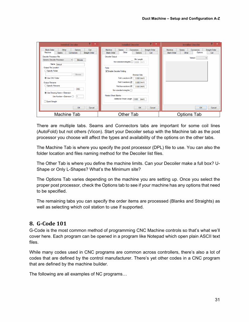
Machine Tab Other Tab Options Tab There are multiple tabs. Seams and Connectors tabs are important for some coil lines (AutoFold) but not others (Vicon). Start your Decoiler setup with the Machine tab as the post processor you choose will affect the types and availability of the options on the other tabs.
The Machine Tab is where you specify the post processor (DPL) file to use. You can also the folder location and files naming method for the Decoiler list files.
The Other Tab is where you define the machine limits. Can your Decoiler make a full box? U-Shape or Only L-Shapes? What’s the Minimum site?
The Options Tab varies depending on the machine you are setting up. Once you select the proper post processor, check the Options tab to see if your machine has any options that need to be specified.
The remaining tabs you can specify the order items are processed (Blanks and Straights) as well as selecting which coil station to use if supported.
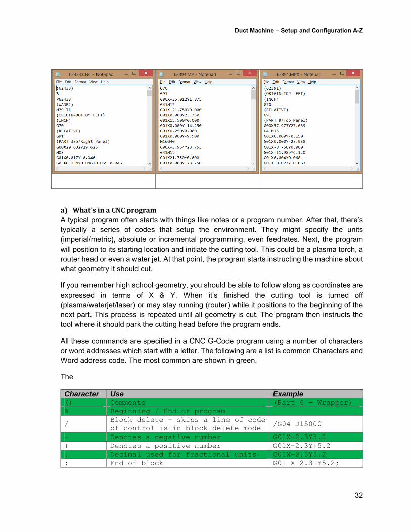
8. G‐Code101G-Code is the most common method of programming CNC Machine controls so that’s what we’ll cover here. Each program can be opened in a program like Notepad which open plain ASCII text files.
While many codes used in CNC programs are common across controllers, there’s also a lot of codes that are defined by the control manufacturer. There’s yet other codes in a CNC program that are defined by the machine builder.
The following are all examples of NC programs…
Duct Machine – Setup and Configuration A-Z
32
a) What’sinaCNCprogramA typical program often starts with things like notes or a program number. After that, there’s typically a series of codes that setup the environment. They might specify the units (imperial/metric), absolute or incremental programming, even feedrates. Next, the program will position to its starting location and initiate the cutting tool. This could be a plasma torch, a router head or even a water jet. At that point, the program starts instructing the machine about what geometry it should cut.
If you remember high school geometry, you should be able to follow along as coordinates are expressed in terms of X & Y. When it’s finished the cutting tool is turned off (plasma/waterjet/laser) or may stay running (router) while it positions to the beginning of the next part. This process is repeated until all geometry is cut. The program then instructs the tool where it should park the cutting head before the program ends.
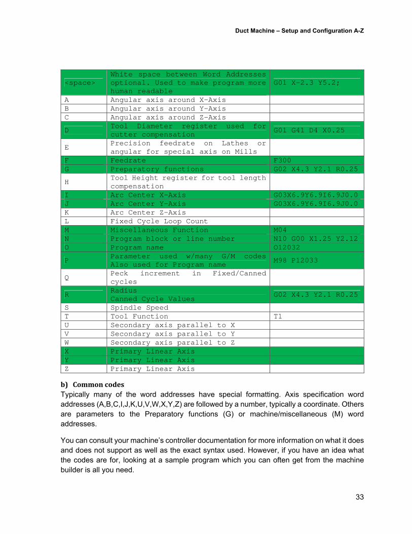
All these commands are specified in a CNC G-Code program using a number of characters or word addresses which start with a letter. The following are a list is common Characters and Word address code. The most common are shown in green.
The
Character Use Example () Comments (Part 6 – Wrapper) % Beginning / End of program
/ Block delete – skips a line of code of control is in block delete mode
/G04 D15000
- Denotes a negative number G01X-2.3Y5.2 + Denotes a positive number G01X-2.3Y+5.2 . Decimal used for fractional units G01X-2.3Y5.2 ; End of block G01 X-2.3 Y5.2;
Duct Machine – Setup and Configuration A-Z
33
<space> White space between Word Addresses optional. Used to make program more human readable
G01 X-2.3 Y5.2;
A Angular axis around X-Axis B Angular axis around Y-Axis C Angular axis around Z-Axis
D Tool Diameter register used for cutter compensation G01 G41 D4 X0.25
E Precision feedrate on Lathes or angular for special axis on Mills
F Feedrate F300 G Preparatory functions G02 X4.3 Y2.1 R0.25
H Tool Height register for tool length compensation
I Arc Center X-Axis G03X6.9Y6.9I6.9J0.0 J Arc Center Y-Axis G03X6.9Y6.9I6.9J0.0 K Arc Center Z-Axis L Fixed Cycle Loop Count M Miscellaneous Function M04 N Program block or line number N10 G00 X1.25 Y2.12 O Program name O12032
P Parameter used w/many G/M codesAlso used for Program name
M98 P12033
Q Peck increment in Fixed/Canned cycles
R Radius Canned Cycle Values
G02 X4.3 Y2.1 R0.25
S Spindle Speed T Tool Function T1 U Secondary axis parallel to X V Secondary axis parallel to Y W Secondary axis parallel to Z X Primary Linear Axis Y Primary Linear Axis Z Primary Linear Axis
b) CommoncodesTypically many of the word addresses have special formatting. Axis specification word addresses (A,B,C,I,J,K,U,V,W,X,Y,Z) are followed by a number, typically a coordinate. Others are parameters to the Preparatory functions (G) or machine/miscellaneous (M) word addresses.
You can consult your machine’s controller documentation for more information on what it does and does not support as well as the exact syntax used. However, if you have an idea what the codes are for, looking at a sample program which you can often get from the machine builder is all you need.
Duct Machine – Setup and Configuration A-Z
34
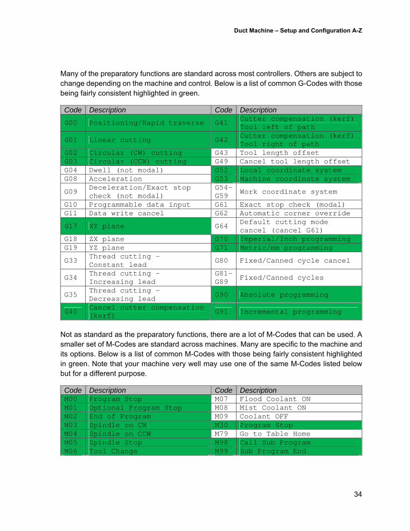
Many of the preparatory functions are standard across most controllers. Others are subject to change depending on the machine and control. Below is a list of common G-Codes with those being fairly consistent highlighted in green.
Code Description Code Description
G00 Positioning/Rapid traverse G41 Cutter compensation (kerf) Tool left of path
G01 Linear cutting G42 Cutter compensation (kerf) Tool right of path
G02 Circular (CW) cutting G43 Tool length offset G03 Circular (CCW) cutting G49 Cancel tool length offset G04 Dwell (not modal) G52 Local coordinate system G08 Acceleration G53 Machine coordinate system
G09 Deceleration/Exact stop check (not modal)
G54-G59
Work coordinate system
G10 Programmable data input G61 Exact stop check (modal) G11 Data write cancel G62 Automatic corner override
G17 XY plane G64 Default cutting mode cancel (cancel G61)
G18 ZX plane G70 Imperial/Inch programming G19 YZ plane G71 Metric/mm programming
G33 Thread cutting - Constant lead
G80 Fixed/Canned cycle cancel
G34 Thread cutting – Increasing lead
G81-G89
Fixed/Canned cycles
G35 Thread cutting – Decreasing lead G90 Absolute programming
G40 Cancel cutter compensation (kerf)
G91 Incremental programming
Not as standard as the preparatory functions, there are a lot of M-Codes that can be used. A smaller set of M-Codes are standard across machines. Many are specific to the machine and its options. Below is a list of common M-Codes with those being fairly consistent highlighted in green. Note that your machine very well may use one of the same M-Codes listed below but for a different purpose.
Code Description Code Description M00 Program Stop M07 Flood Coolant ON M01 Optional Program Stop M08 Mist Coolant ON M02 End of Program M09 Coolant OFF M03 Spindle on CW M30 Program Stop M04 Spindle on CCW M79 Go to Table Home M05 Spindle Stop M98 Call Sub Program M06 Tool Change M99 Sub Program End
Duct Machine – Setup and Configuration A-Z
35
c) SyntaxnuancesThere’s a lot of “rules” of thumb for the syntax in an NC program. A lot of these differences can vary controller to controller or even machine builder to machine builder using the same control. The following are rules of thumb and explain some of the variations you may encounter.
Not all G-Codes are supported on all machines. Consult your documentation for specifics for your machine.
Not all G-Codes have the same function on different controls. The common standard codes are listed earlier but consult your machine’s documentation for specifics.
Most G-Codes are “model” meaning, they can be specified once and remain in effect until canceled or another code is specified changing the machine’s mode.
More than one G-Code can be specified on the same line. You need to make sure you don’t specify codes that conflict with one another but others are perfectly fine. (e.g. G01 and G41/G42 are often used together or G70 & G90)
Some controllers allow codes G00 or G0, G01 or G1, G02 or G2 and are happy. Others require the G00, G01 and G02 with the leading zero specified.
Many G-Codes needs additional parameters using different Word addresses. Consult your machine’s documentation for more specifics.
M-Codes can only be specified one per line (block). Program name (O/P-Codes) are typically optional Program comments are optional Program start/end (%) is not required on all controls. End of Block (;) which marks the end of a line is not required on all controls. Coordinates may or may not contain decimals and instead be specified in 1000ths or
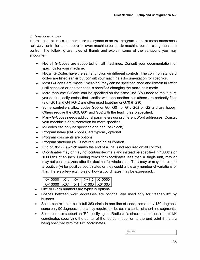
10000ths of an inch. Leading zeros for coordinates less than a single unit, may or may not contain a zero after the decimal for whole units. They may or may not require a positive (+) for positive coordinates or they could allow any number of variations of this. Here’s a few examples of how a coordinates may be expressed…
X+10000 X1. X+1 X+1.0 X10000X+10000 X0.1 X.1 X1000 X01000
Line or Block numbers are typically optional Spaces between word addresses are optional and used only for “readability” by
humans. Some controls can cut a full 360 circle in one line of code, some only 180 degrees,
some only 90 degrees, others may require it to be cut in a series of short line segments. Some controls support an “R” specifying the Radius of a circular cut, others require I/K
coordinates specifying the center of the radius in addition to the end point if the arc being specified with the X/Y coordinates.
(14668) %
Duct Machine – Setup and Configuration A-Z
36
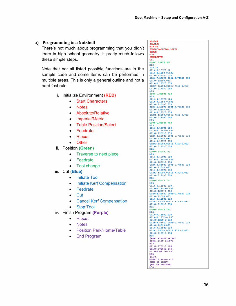
a) ProgramminginaNutshellThere’s not much about programming that you didn’t learn in high school geometry. It pretty much follows these simple steps.
Note that not all listed possible functions are in the sample code and some items can be performed in multiple areas. This is only a general outline and not a hard fast rule.
i. Initialize Environment (RED) Start Characters Notes Absolute/Relative Imperial/Metric Table Position/Select Feedrate Ripcut Other
ii. Position (Green) Traverse to next piece Feedrate Tool change
iii. Cut (Blue) Initiate Tool Initiate Kerf Compensation Feedrate Cut Cancel Kerf Compensation Stop Tool
iv. Finish Program (Purple) Ripcut Notes Position Park/Home/Table End Program
P14668(WADR2) M79 T2 (ORIGIN=BOTTOM LEFT) (INCH) G70 (RELATIVE) G91 G00X7.934Y3.912 M03 F250.0 G01X-0.159Y0.121 G01X-0.125Y-0.033 G01X0.125Y-0.033 G02X-7.550Y0.000I-3.775J0.033 G01X0.125Y0.033 G01X-0.125Y0.033 G02X7.550Y0.000I3.775J-0.033 G01X0.017Y-0.098 M05 G00X-1.858Y6.728 M03 G01X-0.159Y0.120 G01X-0.125Y-0.033 G01X0.125Y-0.033 G02X-5.550Y0.000I-2.775J0.033 G01X0.125Y0.033 G01X-0.125Y0.033 G02X5.550Y0.000I2.775J-0.033 G01X0.017Y-0.098 M05 G00X-1.858Y4.703 M03 G01X-0.159Y0.120 G01X-0.125Y-0.033 G01X0.125Y-0.033 G02X-3.550Y0.000I-1.775J0.033 G01X0.125Y0.033 G01X-0.125Y0.033 G02X3.550Y0.000I1.775J-0.033 G01X0.018Y-0.098 M05 G00X0.141Y3.753 M03 G01X-0.159Y0.120 G01X-0.125Y-0.033 G01X0.125Y-0.033 G02X-3.550Y0.000I-1.775J0.033 G01X0.125Y0.033 G01X-0.125Y0.033 G02X3.550Y0.000I1.775J-0.033 G01X0.018Y-0.098 M05 G00X0.141Y3.753 M03 G01X-0.159Y0.120 G01X-0.125Y-0.033 G01X0.125Y-0.033 G02X-3.550Y0.000I-1.775J0.033 G01X0.125Y0.033 G01X-0.125Y0.033 G02X3.550Y0.000I1.775J-0.033 G01X0.018Y-0.098 M05 G00X0.141Y3.753 M03 G01X-0.159Y0.120 G01X-0.125Y-0.033 G01X0.125Y-0.033 G02X-3.550Y0.000I-1.775J0.033 G01X0.125Y0.033 G01X-0.125Y0.033 G02X3.550Y0.000I1.775J-0.033 G01X0.018Y-0.098 M05 (PART RIPCUT AFTER) G00X4.218Y-26.572 M03 G01X0.173Y-0.100 G01X0.000Y59.874 G01X-0.087Y-0.050 M05 (PARK) G00X112.403Y0.613 (END OF SHEET) (END OF PROGRAM) M30
Duct Machine – Setup and Configuration A-Z
37
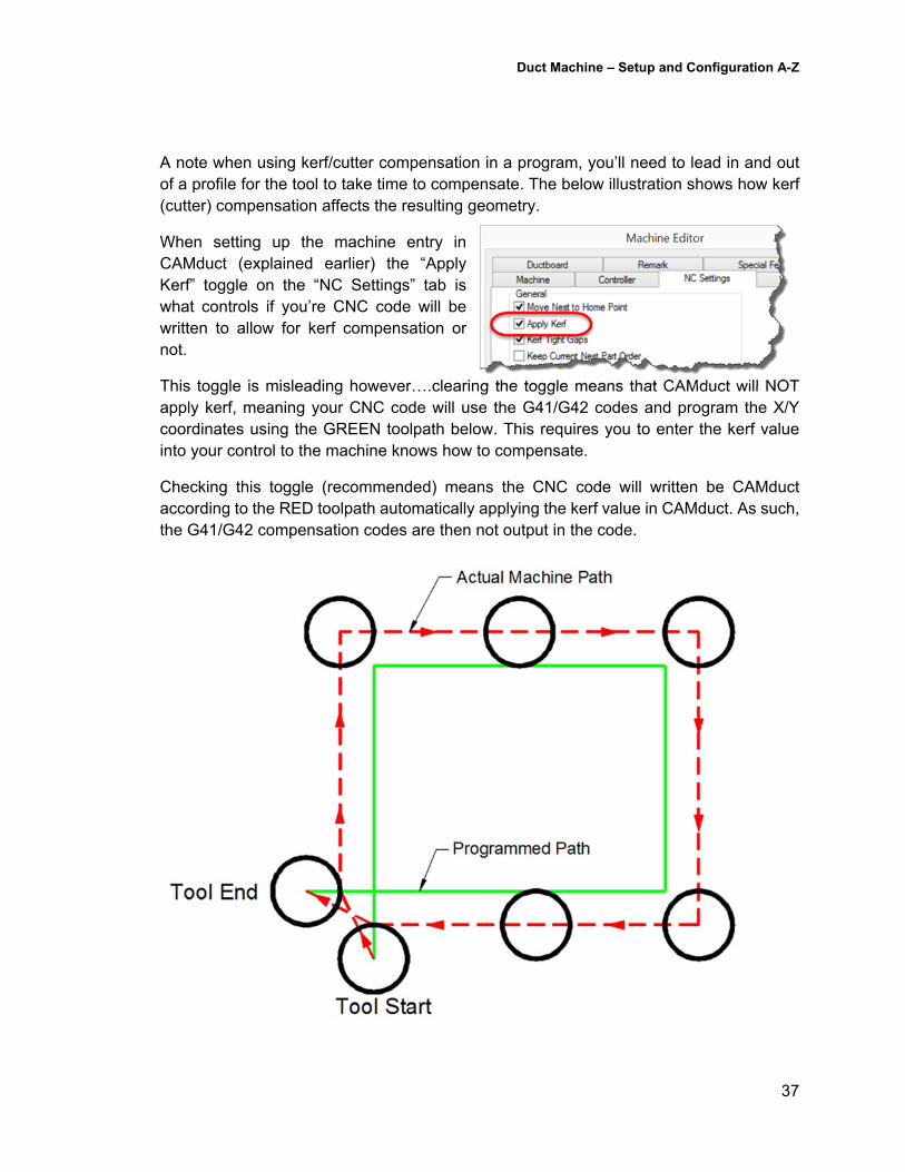
A note when using kerf/cutter compensation in a program, you’ll need to lead in and out of a profile for the tool to take time to compensate. The below illustration shows how kerf (cutter) compensation affects the resulting geometry.
When setting up the machine entry in CAMduct (explained earlier) the “Apply Kerf” toggle on the “NC Settings” tab is what controls if you’re CNC code will be written to allow for kerf compensation or not.
This toggle is misleading however….clearing the toggle means that CAMduct will NOT apply kerf, meaning your CNC code will use the G41/G42 codes and program the X/Y coordinates using the GREEN toolpath below. This requires you to enter the kerf value into your control to the machine knows how to compensate.
Checking this toggle (recommended) means the CNC code will written be CAMduct according to the RED toolpath automatically applying the kerf value in CAMduct. As such, the G41/G42 compensation codes are then not output in the code.
Duct Machine – Setup and Configuration A-Z
38
PartV–OtherConsiderations
1. Non‐SupportedMachines/OptionsCAMduct support most of the machines in the duct fabrication industry. None the less, each year the list of Post Processors gets just a little bit longer. If you have a new generation machine or something CAMduct doesn’t currently support, you’re not dead in the water yet. You might need to take a little bit of time using trial and error to find a VPL post that gets you close.
From there, a specially formatted MACHINE.CFG file can be placed in the same folder as the machine’s setup files. (.\Database\<machine>.mch>\Machine.Cfg). Use of this file and how to generate it is not supported by end users and documentation is virtually non-existent.
While you can get an idea what’s happening by looking in a sample file if you find one, your best bet it to bring in a consultant specializing in this type of work or using Autodesk support to get you through it. This is something that 99.9% of customers should never need to do and by involving a consultant or Autodesk, the next version of CAMduct may just ship with a native VPL that covers your machine.
2. Hybrid‐CommunicationsWhen it comes to connecting your CAM systems to your machines, there’s a lot of options. We covered USB, Serial and Ethernet (standard networking) earlier. However, there’s more options available. Ethernet by far is the best choice, plug your controller into your network and you’re good to go.
But what if you have older serial based machine controllers? Is Serial really the only options? Luckily no, there’s a couple good options…
a) SerialtoUSBMost systems come with at least 1 or 2 serial ports. If you need more, you need an expansion card. Some systems may not even have any. If you do a search, you’ll find a number of USB to Serial devices available. These devices usually create a “virtual” serial port(s) on your system and maps it to your computer’s USB port. Your communications software (which ships w/CAMduct) then references those virtual COM ports (if you recall earlier, serial ports are addressed as COM1, COM2, etc.). The communications software is none the wiser and operates how it always has.
What’s nice about a system like this, is it’s easily portable from one computer system to another in case one goes down. Just reinstall the USB to Serial drivers or software and its plug and play to get a new system back on line.
The one drawback, is that USB ports can be susceptible to the resource demands of your system. It’s not recommended to use a production system that’s performing processor
Duct Machine – Setup and Configuration A-Z
39
intensive operations or communications could fail if your controller requests a file and your system is slow to respond via the USB port.
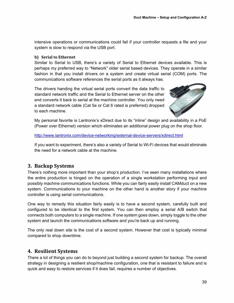
b) SerialtoEthernetSimilar to Serial to USB, there’s a variety of Serial to Ethernet devices available. This is perhaps my preferred way to “Network” older serial based devices. They operate in a similar fashion in that you install drivers on a system and create virtual serial (COM) ports. The communications software references the serial ports as it always has.
The drivers handing the virtual serial ports convert the data traffic to standard network traffic and the Serial to Ethernet server on the other end converts it back to serial at the machine controller. You only need a standard network cable (Cat 5e or Cat 6 rated is preferred) dropped to each machine.
My personal favorite is Lantronix’s xDirect due to its “inline” design and availability in a PoE (Power over Ethernet) version which eliminates an additional power plug on the shop floor.
http://www.lantronix.com/device-networking/external-device-servers/xdirect.html
If you want to experiment, there’s also a variety of Serial to Wi-Fi devices that would eliminate the need for a network cable at the machine.
3. BackupSystemsThere’s nothing more important than your shop’s production. I’ve seen many installations where the entire production is hinged on the operation of a single workstation performing input and possibly machine communications functions. While you can fairly easily install CAMduct on a new system. Communications to your machine on the other hand is another story if your machine controller is using serial communications.
One way to remedy this situation fairly easily is to have a second system, carefully built and configured to be identical to the first system. You can then employ a serial A/B switch that connects both computers to a single machine. If one system goes down, simply toggle to the other system and launch the communications software and you’re back up and running.
The only real down site is the cost of a second system. However that cost is typically minimal compared to shop downtime.
4. ResilientSystemsThere a lot of things you can do to beyond just building a second system for backup. The overall strategy in designing a resilient shop/machine configuration, one that is resistant to failure and is quick and easy to restore services if it does fail, requires a number of objectives.
Duct Machine – Setup and Configuration A-Z
40
Objective 1: Separate the processes of “Shop Input” (the work performed within CAMduct processing MAJ’s) and “Machine Communications” (sending the NC files to the machine controller via serial connection). By separating these processes to different systems, if any one system goes down, the other process can stay running. Furthermore, to restore the failed process (Shop Input or Machine Communications”), you’re only restoring and setting up one process instead of 2. This makes restoration of services ½ the work it would be otherwise.
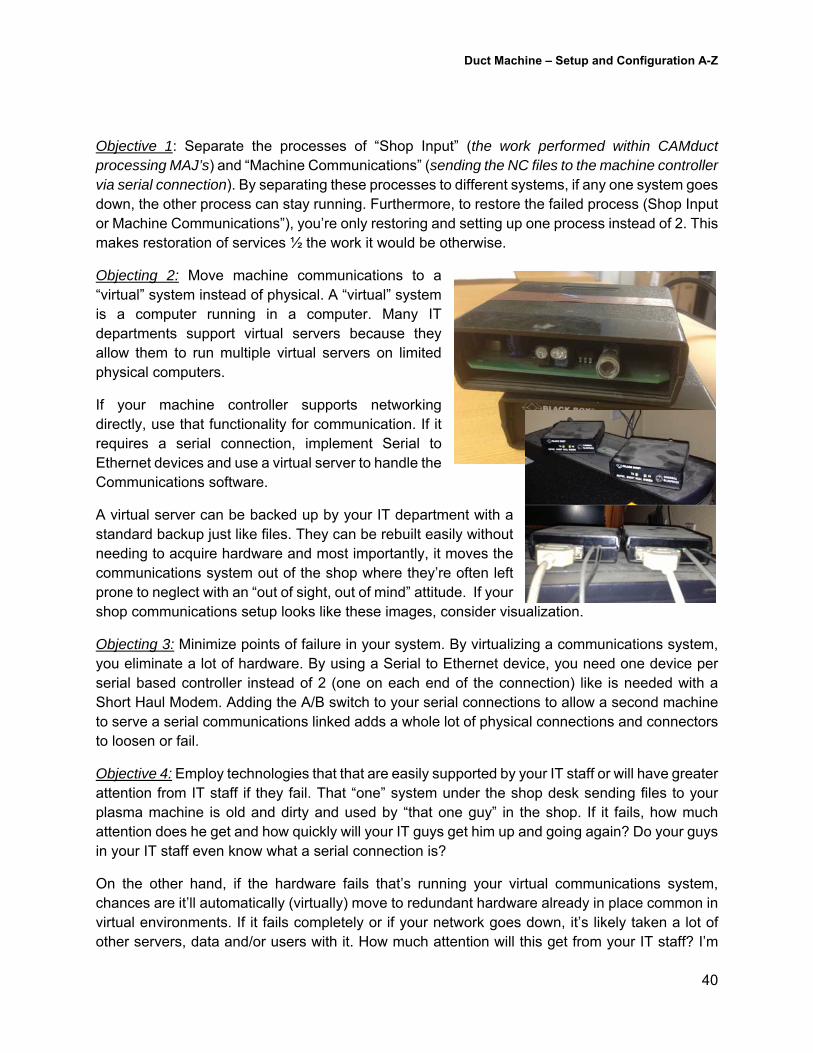
Objecting 2: Move machine communications to a “virtual” system instead of physical. A “virtual” system is a computer running in a computer. Many IT departments support virtual servers because they allow them to run multiple virtual servers on limited physical computers.
If your machine controller supports networking directly, use that functionality for communication. If it requires a serial connection, implement Serial to Ethernet devices and use a virtual server to handle the Communications software.
A virtual server can be backed up by your IT department with a standard backup just like files. They can be rebuilt easily without needing to acquire hardware and most importantly, it moves the communications system out of the shop where they’re often left prone to neglect with an “out of sight, out of mind” attitude. If your shop communications setup looks like these images, consider visualization.
Objecting 3: Minimize points of failure in your system. By virtualizing a communications system, you eliminate a lot of hardware. By using a Serial to Ethernet device, you need one device per serial based controller instead of 2 (one on each end of the connection) like is needed with a Short Haul Modem. Adding the A/B switch to your serial connections to allow a second machine to serve a serial communications linked adds a whole lot of physical connections and connectors to loosen or fail.
Objective 4: Employ technologies that that are easily supported by your IT staff or will have greater attention from IT staff if they fail. That “one” system under the shop desk sending files to your plasma machine is old and dirty and used by “that one guy” in the shop. If it fails, how much attention does he get and how quickly will your IT guys get him up and going again? Do your guys in your IT staff even know what a serial connection is?
On the other hand, if the hardware fails that’s running your virtual communications system, chances are it’ll automatically (virtually) move to redundant hardware already in place common in virtual environments. If it fails completely or if your network goes down, it’s likely taken a lot of other servers, data and/or users with it. How much attention will this get from your IT staff? I’m
Duct Machine – Setup and Configuration A-Z
41
guessing this would be the type of thing they’d work through the night to get back up and running. How likely are they going to be to do that for “Sheetmetal Bob” stuck back in the corner of the shop?
Objective 5: Network license software. By network licensing your CAMduct software, the license can easily “float” to another system for shop input system if the first fails. Additionally, you could install the software on every detailers system or even an accountant’s. Any system would work for shop input as the license floats to it and communications aren’t tied to it. This has the added benefit of allowing you to quickly scale up to additional CAMduct stations if needed by simply adding licenses into the pool.
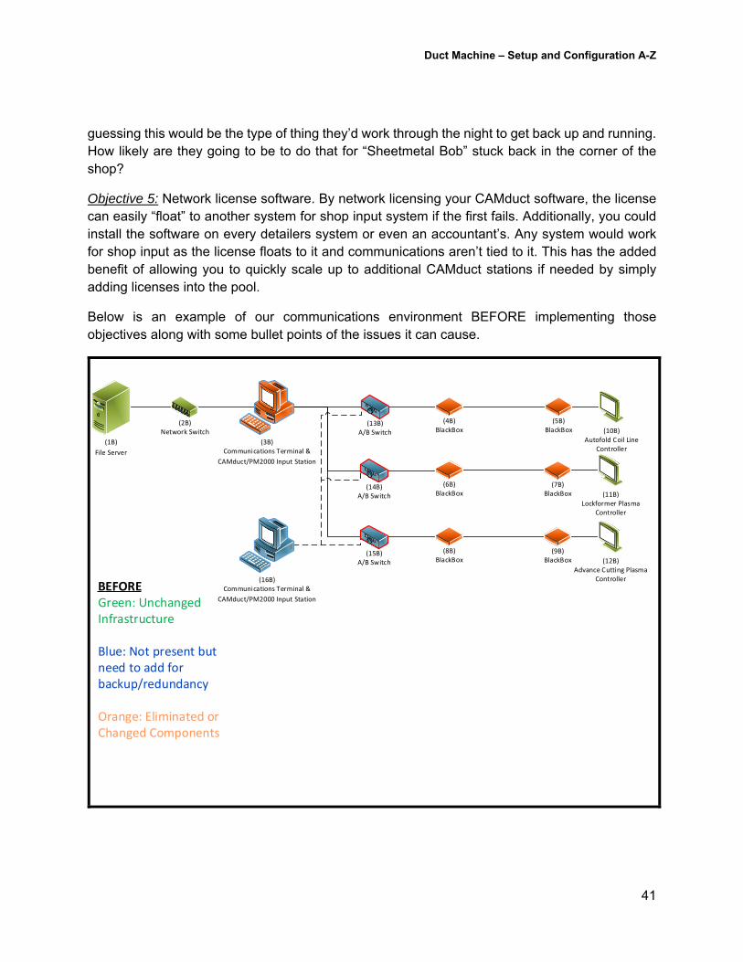
Below is an example of our communications environment BEFORE implementing those objectives along with some bullet points of the issues it can cause.
BEFOREGreen: Unchanged Infrastructure
Blue: Not present but need to add for backup/redundancy
Orange: Eliminated or Changed Components
(10B)Autofold Coil Line
Controller(1B)
File Server
(4B)BlackBox
(13B)A/B Switch
(2B)Network Switch
(3B)Communications Terminal &
CAMduct/PM2000 Input Station
(5B)BlackBox
(11B)Lockformer Plasma
Controller
(6B)BlackBox
(14B)A/B Switch
(7B)BlackBox
(12B)Advance Cutting Plasma
Controller
(8B)BlackBox
(15B)A/B Switch
(9B)BlackBox
(16B)Communications Terminal &
CAMduct/PM2000 Input Station
Duct Machine – Setup and Configuration A-Z
42
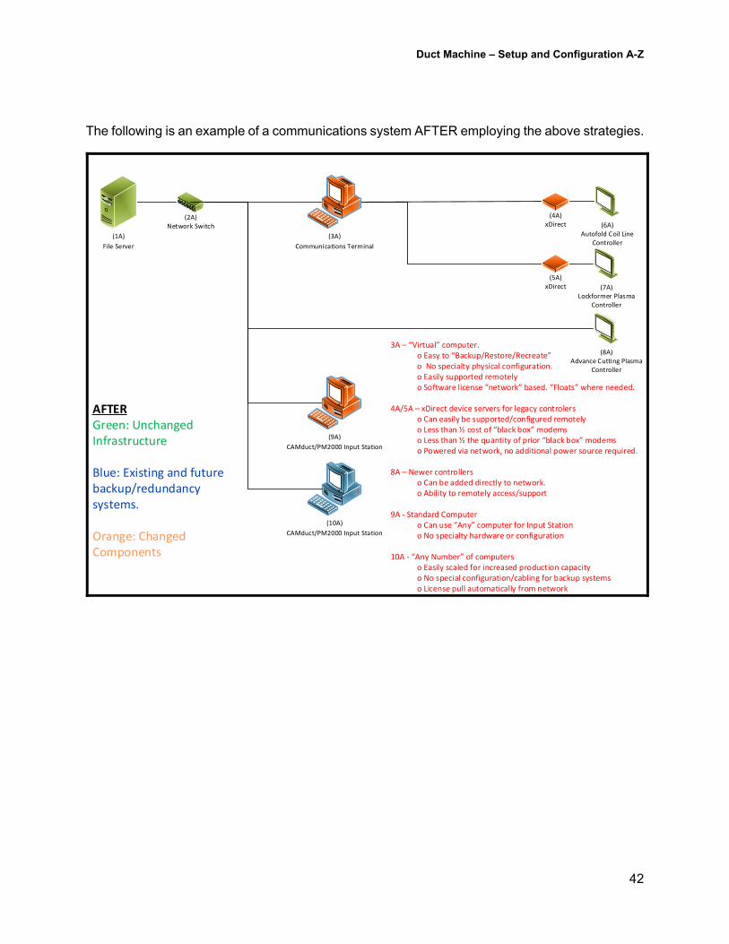
The following is an example of a communications system AFTER employing the above strategies.
(6A)Autofold Coil Line
Controller(1A)
File Server
(3A)
Communications Terminal
(4A)xDirect
(7A)Lockformer Plasma
Controller
(5A)xDirect
(8A)Advance Cutting Plasma
Controller
(2A)Network Switch
(10A)
CAMduct/PM2000 Input Station
3A – “Virtual” computer.o Easy to “Backup/Restore/Recreate”o No specialty physical configuration. o Easily supported remotelyo Software license “network” based. “Floats” where needed.
4A/5A – xDirect device servers for legacy controlerso Can easily be supported/configured remotelyo Less than ½ cost of “black box” modemso Less than ½ the quantity of prior “black box” modemso Powered via network, no additional power source required.
8A – Newer controllerso Can be added directly to network.o Ability to remotely access/support
9A ‐ Standard Computero Can use “Any” computer for Input Stationo No specialty hardware or configuration
10A ‐ “Any Number” of computerso Easily scaled for increased production capacityo No special configuration/cabling for backup systemso License pull automatically from network
(9A)
CAMduct/PM2000 Input Station
AFTERGreen: Unchanged Infrastructure
Blue: Existing and future backup/redundancy systems.
Orange: Changed Components
Duct Machine – Setup and Configuration A-Z
43
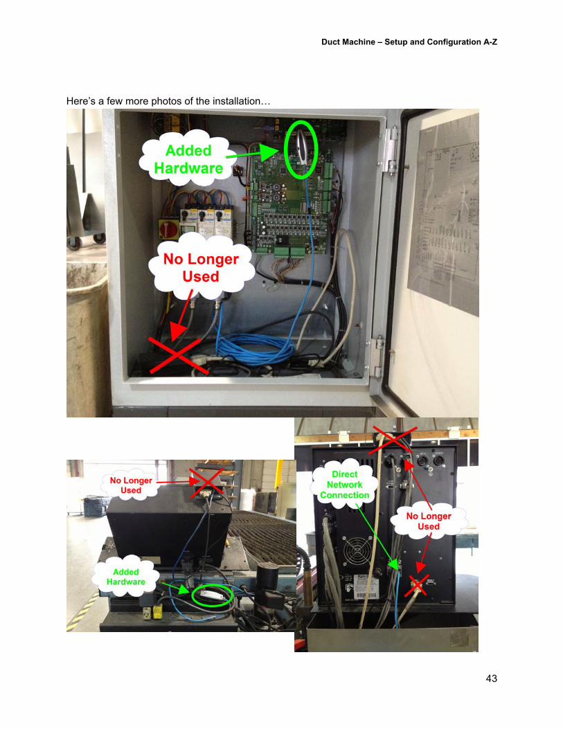
Here’s a few more photos of the installation…