Embed Size (px)
Citation preview
MSP430 Hardware Tools
User's Guide
Literature Number: SLAU278C
May 2009–Revised November 2009

2 SLAU278C–May 2009–Revised November 2009Submit Documentation Feedback
Copyright © 2009, Texas Instruments Incorporated
Contents
Preface ....................................................................................................................................... 7
1 Get Started Now! ............................................................................................................... 111.1 Flash Emulation Tool (FET) Overview .................................................................................. 121.2 Kit Contents, MSP-FET430PIF .......................................................................................... 121.3 Kit Contents, eZ430-F2013 .............................................................................................. 121.4 Kit Contents, eZ430-T2012 .............................................................................................. 121.5 Kit Contents, eZ430-RF2500 ............................................................................................ 131.6 Kit Contents, eZ430-RF2500T ........................................................................................... 131.7 Kit Contents, eZ430-RF2500-SEH ...................................................................................... 131.8 Kit Contents, eZ430-Chronos-xxx ....................................................................................... 131.9 Kit Contents, MSP-FET430UIF .......................................................................................... 131.10 Kit Contents, MSP-FET430Uxx .......................................................................................... 141.11 Kit Contents, FET430F6137RF900 ..................................................................................... 151.12 Kit Contents, MSP-TS430xx ............................................................................................. 161.13 Kit Contents, EM430F6137RF900 ...................................................................................... 171.14 Hardware Installation, MSP-FET430PIF ............................................................................... 171.15 Hardware Installation, MSP-FET430UIF ............................................................................... 181.16 Hardware Installation, eZ430-F2013, eZ430-RF2500, eZ430-Chronos ............................................ 181.17 Hardware Installation, MSP-FET430Uxx, MSP-TS430xxx, FET430F6137RF900, EM430F6137RF900 ...... 181.18 Important MSP430 Documents on the CD-ROM and Web .......................................................... 19
2 Design Considerations for In-Circuit Programming ............................................................... 212.1 Signal Connections for In-System Programming and Debugging ................................................... 222.2 External Power ............................................................................................................. 252.3 Bootstrap Loader .......................................................................................................... 25
A Frequently Asked Questions and Known Issues ................................................................... 27A.1 Hardware FAQs ............................................................................................................ 28A.2 Known Issues .............................................................................................................. 30
B Hardware .......................................................................................................................... 31B.1 MSP-TS430PW14 ......................................................................................................... 32B.2 MSP-TS430DW28 ......................................................................................................... 35B.3 MSP-TS430PW28 ......................................................................................................... 38B.4 MSP-TS430DA38 .......................................................................................................... 41B.5 MSP-TS430QFN23x0 ..................................................................................................... 44B.6 MSP-TS430DL48 .......................................................................................................... 47B.7 MSP-TS430PM64 ......................................................................................................... 50B.8 MSP-TS430PM64A ....................................................................................................... 53B.9 MSP-TS430PN80 .......................................................................................................... 56B.10 MSP-TS430PN80USB .................................................................................................... 59B.11 MSP-TS430PZ100 ........................................................................................................ 63B.12 MSP-TS430PZ100A ....................................................................................................... 66B.13 MSP-TS430PZ5x100 ..................................................................................................... 69B.14 EM430F6137RF900 ....................................................................................................... 72B.15 MSP-FET430PIF .......................................................................................................... 76B.16 MSP-FET430UIF .......................................................................................................... 78
3SLAU278C–May 2009–Revised November 2009 ContentsSubmit Documentation Feedback
Copyright © 2009, Texas Instruments Incorporated
www.ti.com
B.16.1 MSP-FET430UIF Revision History ............................................................................ 83
C Hardware Installation Guide ................................................................................................ 85C.1 Hardware Installation ...................................................................................................... 86
Document Revision History ......................................................................................................... 92
4 Contents SLAU278C–May 2009–Revised November 2009Submit Documentation Feedback
Copyright © 2009, Texas Instruments Incorporated
www.ti.com
List of Figures
2-1. Signal Connections for 4-Wire JTAG Communication................................................................ 24
2-2. Signal Connections for 2-Wire JTAG Communication (Spy-Bi-Wire)............................................... 24
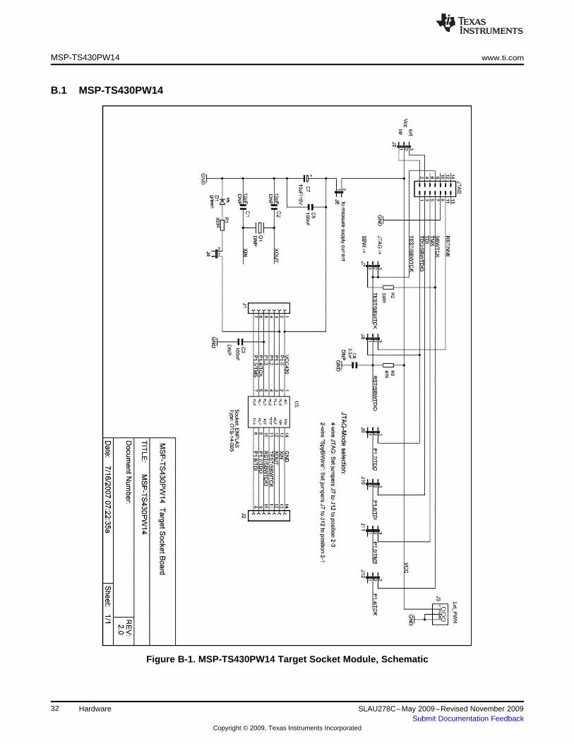
B-1. MSP-TS430PW14 Target Socket Module, Schematic ............................................................... 33
B-2. MSP-TS430PW14 Target Socket Module, PCB ...................................................................... 33
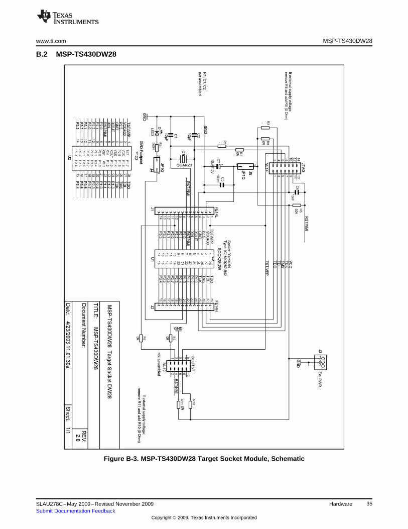
B-3. MSP-TS430DW28 Target Socket Module, Schematic ............................................................... 36
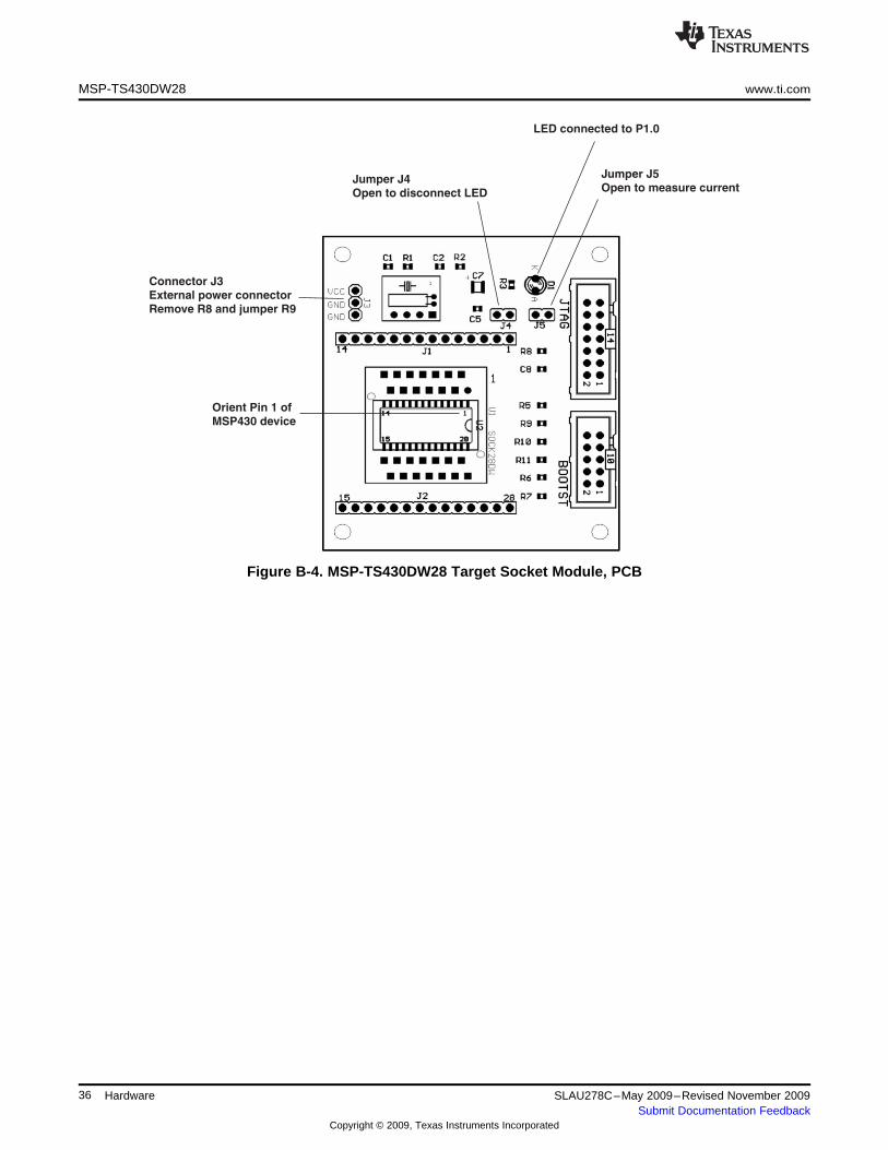
B-4. MSP-TS430DW28 Target Socket Module, PCB ...................................................................... 36
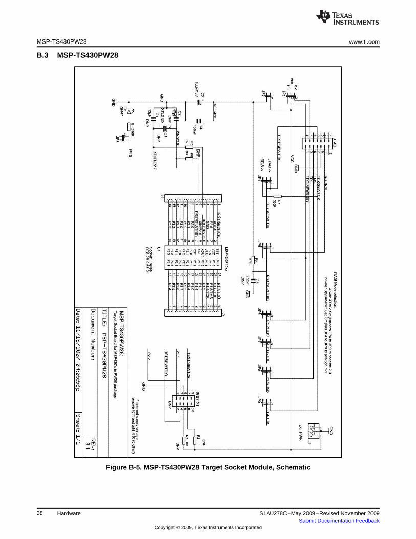
B-5. MSP-TS430PW28 Target Socket Module, Schematic ............................................................... 39
B-6. MSP-TS430PW28 Target Socket Module, PCB ...................................................................... 39
B-7. MSP-TS430DA38 Target Socket Module, Schematic ................................................................ 42
B-8. MSP-TS430DA38 Target Socket Module, PCB ....................................................................... 42
B-9. MSP-TS430QFN23x0 Target Socket Module, Schematic ........................................................... 45
B-10. MSP-TS430QFN23x0 Target Socket Module, PCB .................................................................. 45
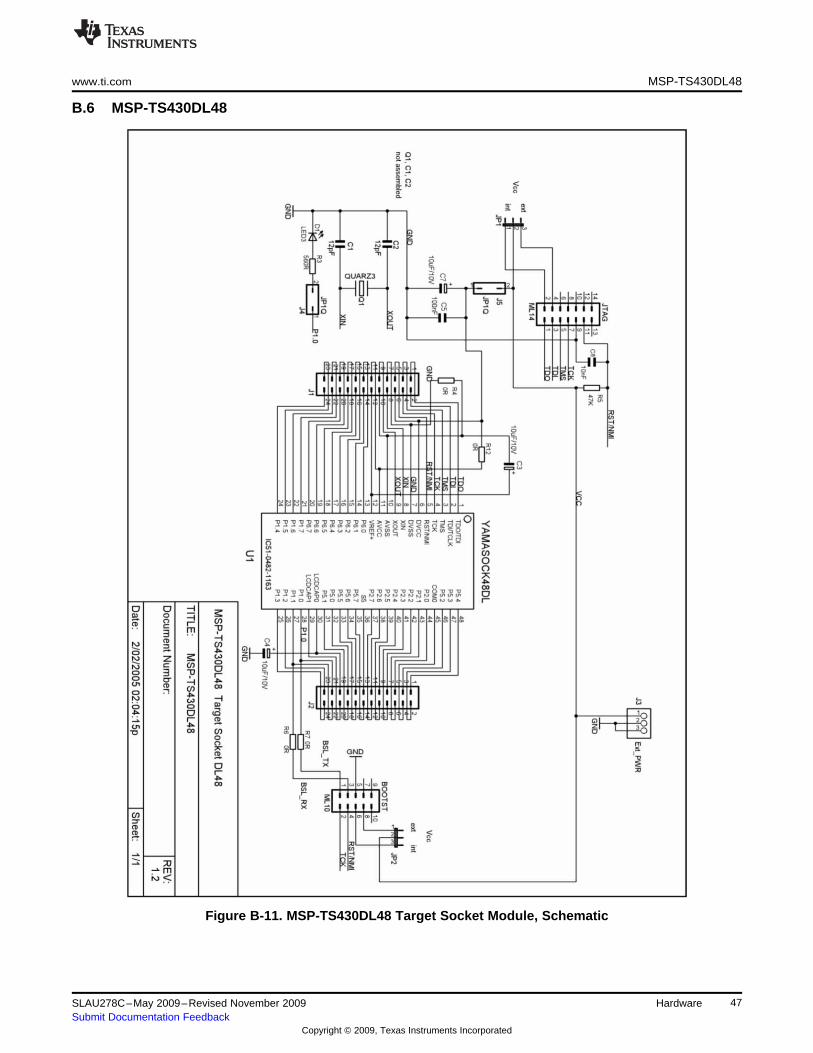
B-11. MSP-TS430DL48 Target Socket Module, Schematic ................................................................ 48
B-12. MSP-TS430DL48 Target Socket Module, PCB ....................................................................... 48
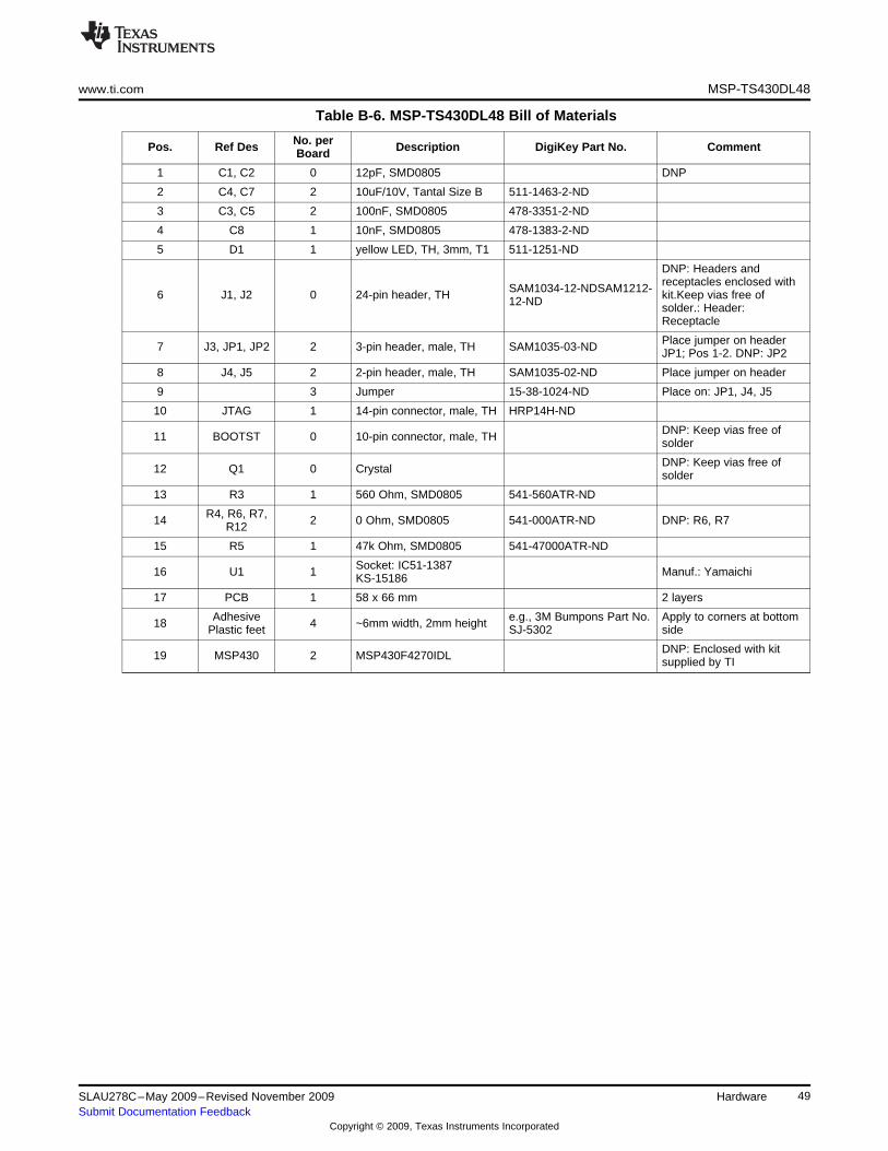
B-13. MSP-TS430PM64 Target Socket Module, Schematic................................................................ 51
B-14. MSP-TS430PM64 Target Socket Module, PCB....................................................................... 51
B-15. MSP-TS430PM64A Target Socket Module, Schematic .............................................................. 54
B-16. MSP-TS430PM64A Target Socket Module, PCB ..................................................................... 54
B-17. MSP-TS430PN80 Target Socket Module, Schematic ................................................................ 57
B-18. MSP-TS430PN80 Target Socket Module, PCB ....................................................................... 57
B-19. MSP-TS430PN80USB Target Socket Module, Schematic .......................................................... 60
B-20. MSP-TS430PN80USB Target Socket Module, PCB.................................................................. 60
B-21. MSP-TS430PZ100 Target Socket Module, Schematic ............................................................... 64
B-22. MSP-TS430PZ100 Target Socket Module, PCB ...................................................................... 64
B-23. MSP-TS430PZ100A Target Socket Module, Schematic ............................................................. 67
B-24. MSP-TS430PZ100A Target Socket Module, PCB .................................................................... 67
B-25. MSP-TS430PZ5x100 Target Socket Module, Schematic ............................................................ 70
B-26. MSP-TS430PZ5x100 Target Socket Module, PCB ................................................................... 70
B-27. EM430F6137RF900 Target Socket Module, Schematic ............................................................. 73
B-28. EM430F6137RF900 Target Socket Module, PCB .................................................................... 73
B-29. MSP-FET430PIF FET Interface Module, Schematic ................................................................. 77
B-30. MSP-FET430PIF FET Interface Module, PCB ........................................................................ 77
B-31. MSP-FET430UIF USB Interface, Schematic (1 of 4) ................................................................. 79
B-32. MSP-FET430UIF USB Interface, Schematic (2 of 4) ................................................................. 80
B-33. MSP-FET430UIF USB Interface, Schematic (3 of 4) ................................................................. 81
B-34. MSP-FET430UIF USB Interface, Schematic (4 of 4) ................................................................. 82
B-35. MSP-FET430UIF USB Interface, PCB ................................................................................. 82
C-1. Windows XP Hardware Recognition .................................................................................... 86
C-2. Windows XP Hardware Wizard .......................................................................................... 86
C-3. Windows XP Driver Location Selection Folder ........................................................................ 87
C-4. Windows XP Driver Installation .......................................................................................... 88
C-5. Device Manager Using MSP-FET430UIF or eZ430-F2013 (CCE and CCS Only) ............................... 90
C-6. Device Manager Using MSP-FET430UIF or eZ430-F2013 (IAR Only) ............................................ 91
C-7. Device Manager Using eZ430-RF2500 (CCE/CCS and IAR) ....................................................... 91
5SLAU278C–May 2009–Revised November 2009 List of FiguresSubmit Documentation Feedback
Copyright © 2009, Texas Instruments Incorporated
www.ti.com
List of Tables
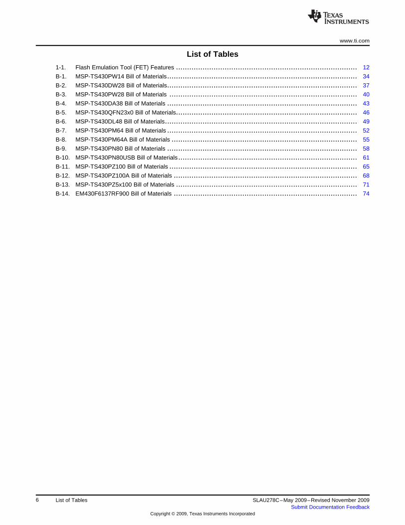
1-1. Flash Emulation Tool (FET) Features .................................................................................. 12
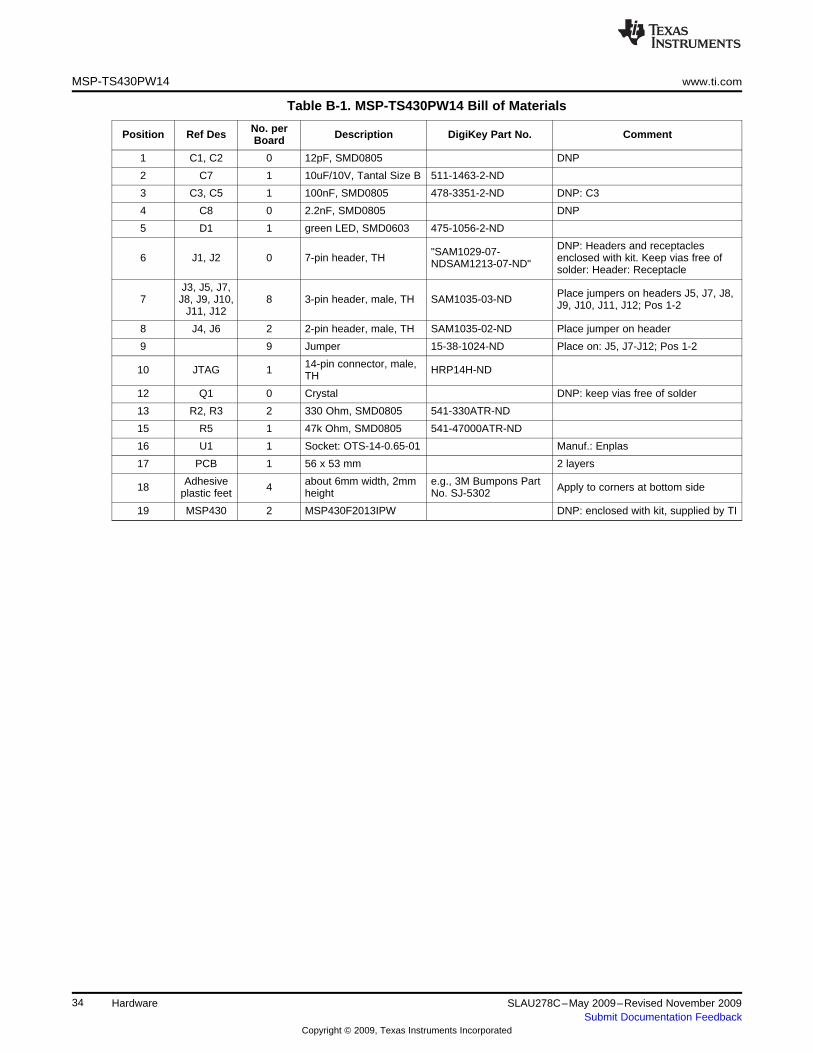
B-1. MSP-TS430PW14 Bill of Materials...................................................................................... 34
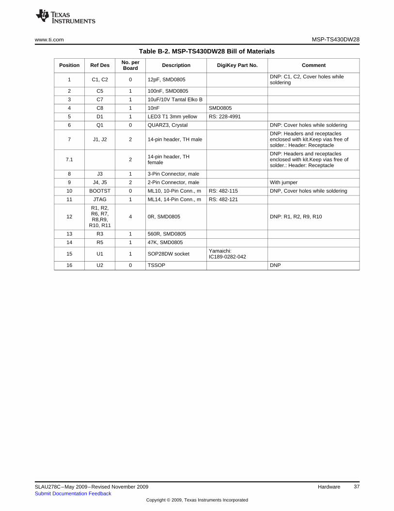
B-2. MSP-TS430DW28 Bill of Materials...................................................................................... 37
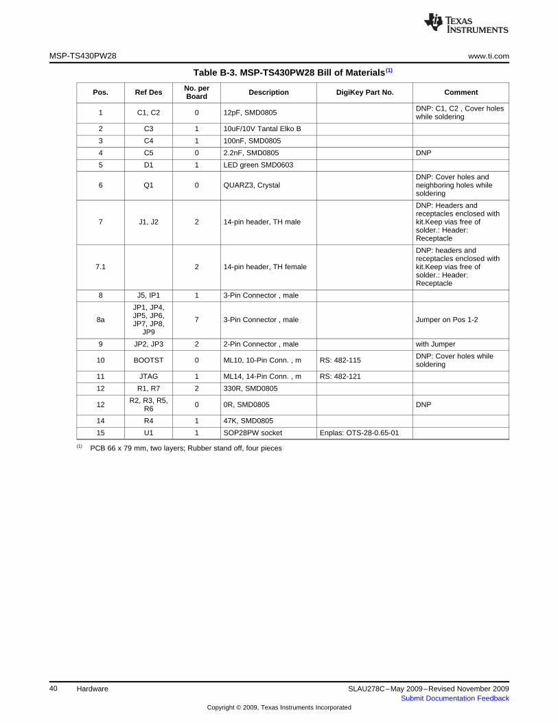
B-3. MSP-TS430PW28 Bill of Materials ..................................................................................... 40
B-4. MSP-TS430DA38 Bill of Materials ...................................................................................... 43
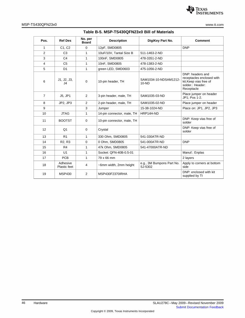
B-5. MSP-TS430QFN23x0 Bill of Materials.................................................................................. 46
B-6. MSP-TS430DL48 Bill of Materials....................................................................................... 49
B-7. MSP-TS430PM64 Bill of Materials ...................................................................................... 52
B-8. MSP-TS430PM64A Bill of Materials .................................................................................... 55
B-9. MSP-TS430PN80 Bill of Materials ...................................................................................... 58
B-10. MSP-TS430PN80USB Bill of Materials................................................................................. 61
B-11. MSP-TS430PZ100 Bill of Materials ..................................................................................... 65
B-12. MSP-TS430PZ100A Bill of Materials ................................................................................... 68
B-13. MSP-TS430PZ5x100 Bill of Materials .................................................................................. 71
B-14. EM430F6137RF900 Bill of Materials ................................................................................... 74
6 List of Tables SLAU278C–May 2009–Revised November 2009Submit Documentation Feedback
Copyright © 2009, Texas Instruments Incorporated
PrefaceSLAU278C–May 2009–Revised November 2009
Read This First
About This Manual
This manual describes the hardware of the Texas Instruments MSP-FET430 Flash Emulation Tool (FET).The FET is the program development tool for the MSP430 ultra-low-power microcontroller. Both availableinterface types, the parallel port interface and the USB interface, are described.
How to Use This Manual
Read and follow the instructions in Chapter 1. This chapter lists the contents of the FET, providesinstructions on installing the hardware and according software drivers. After you see how quick and easy itis to use the development tools, TI recommends that you read all of this manual.
This manual describes the setup and operation of the FET but does not fully describe the MSP430 or thedevelopment software systems. For details of these items, see the appropriate TI documents listed inSection 1.18.
This manual applies to the following tools (and devices):
• MSP-FET430PIF (debug interface with parallel port connection, for all MSP430 flash-based devices)• MSP-FET430UIF (debug interface with USB connection, for all MSP430 flash-based devices)• eZ430-F2013 (USB stick form factor interface with attached MSP430F2013 target, for all
MSP430F20xx devices)• eZ430-T2012 (three MSP430F2012 based target boards)• eZ430-RF2500 (USB stick form factor interface with attached MSP430F2274/CC2500 target, for all
MSP430F20xx and MSP430F22xx devices)• eZ430-RF2500T (one MSP430F2274/CC2500 target board including battery pack)• eZ430-RF2500-SEH (USB stick form factor interface with attached MSP430F2274/CC2500 target and
solar energy harvesting module)• eZ430-Chronos-xxx (USB stick form factor interface with CC430F6137 based development system
contained in a watch. Includes <1GHz RF USB access point)
7SLAU278C–May 2009–Revised November 2009 Read This FirstSubmit Documentation Feedback
Copyright © 2009, Texas Instruments Incorporated
How to Use This Manual www.ti.com
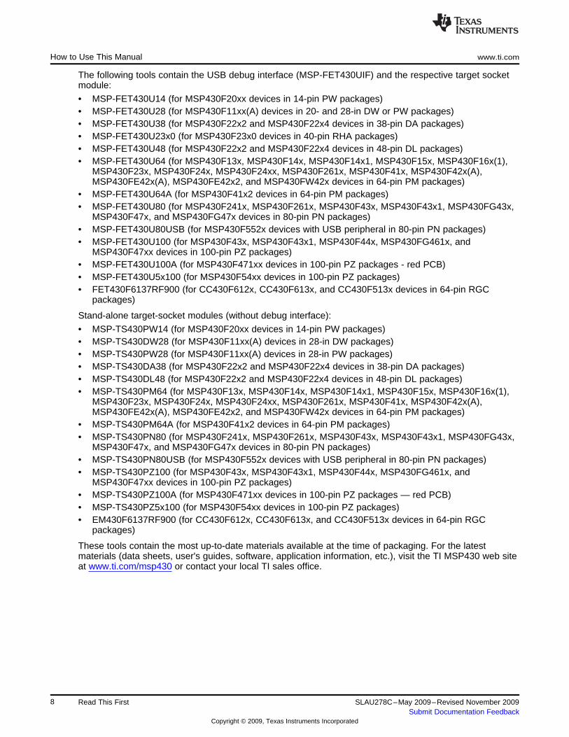
The following tools contain the USB debug interface (MSP-FET430UIF) and the respective target socketmodule:
• MSP-FET430U14 (for MSP430F20xx devices in 14-pin PW packages)• MSP-FET430U28 (for MSP430F11xx(A) devices in 20- and 28-in DW or PW packages)• MSP-FET430U38 (for MSP430F22x2 and MSP430F22x4 devices in 38-pin DA packages)• MSP-FET430U23x0 (for MSP430F23x0 devices in 40-pin RHA packages)• MSP-FET430U48 (for MSP430F22x2 and MSP430F22x4 devices in 48-pin DL packages)• MSP-FET430U64 (for MSP430F13x, MSP430F14x, MSP430F14x1, MSP430F15x, MSP430F16x(1),
MSP430F23x, MSP430F24x, MSP430F24xx, MSP430F261x, MSP430F41x, MSP430F42x(A),MSP430FE42x(A), MSP430FE42x2, and MSP430FW42x devices in 64-pin PM packages)
• MSP-FET430U64A (for MSP430F41x2 devices in 64-pin PM packages)• MSP-FET430U80 (for MSP430F241x, MSP430F261x, MSP430F43x, MSP430F43x1, MSP430FG43x,
MSP430F47x, and MSP430FG47x devices in 80-pin PN packages)• MSP-FET430U80USB (for MSP430F552x devices with USB peripheral in 80-pin PN packages)• MSP-FET430U100 (for MSP430F43x, MSP430F43x1, MSP430F44x, MSP430FG461x, and
MSP430F47xx devices in 100-pin PZ packages)• MSP-FET430U100A (for MSP430F471xx devices in 100-pin PZ packages - red PCB)• MSP-FET430U5x100 (for MSP430F54xx devices in 100-pin PZ packages)• FET430F6137RF900 (for CC430F612x, CC430F613x, and CC430F513x devices in 64-pin RGC
packages)
Stand-alone target-socket modules (without debug interface):
• MSP-TS430PW14 (for MSP430F20xx devices in 14-pin PW packages)• MSP-TS430DW28 (for MSP430F11xx(A) devices in 28-in DW packages)• MSP-TS430PW28 (for MSP430F11xx(A) devices in 28-in PW packages)• MSP-TS430DA38 (for MSP430F22x2 and MSP430F22x4 devices in 38-pin DA packages)• MSP-TS430DL48 (for MSP430F22x2 and MSP430F22x4 devices in 48-pin DL packages)• MSP-TS430PM64 (for MSP430F13x, MSP430F14x, MSP430F14x1, MSP430F15x, MSP430F16x(1),
MSP430F23x, MSP430F24x, MSP430F24xx, MSP430F261x, MSP430F41x, MSP430F42x(A),MSP430FE42x(A), MSP430FE42x2, and MSP430FW42x devices in 64-pin PM packages)
• MSP-TS430PM64A (for MSP430F41x2 devices in 64-pin PM packages)• MSP-TS430PN80 (for MSP430F241x, MSP430F261x, MSP430F43x, MSP430F43x1, MSP430FG43x,
MSP430F47x, and MSP430FG47x devices in 80-pin PN packages)• MSP-TS430PN80USB (for MSP430F552x devices with USB peripheral in 80-pin PN packages)• MSP-TS430PZ100 (for MSP430F43x, MSP430F43x1, MSP430F44x, MSP430FG461x, and
MSP430F47xx devices in 100-pin PZ packages)• MSP-TS430PZ100A (for MSP430F471xx devices in 100-pin PZ packages — red PCB)• MSP-TS430PZ5x100 (for MSP430F54xx devices in 100-pin PZ packages)• EM430F6137RF900 (for CC430F612x, CC430F613x, and CC430F513x devices in 64-pin RGC
packages)
These tools contain the most up-to-date materials available at the time of packaging. For the latestmaterials (data sheets, user's guides, software, application information, etc.), visit the TI MSP430 web siteat www.ti.com/msp430 or contact your local TI sales office.
8 Read This First SLAU278C–May 2009–Revised November 2009Submit Documentation Feedback
Copyright © 2009, Texas Instruments Incorporated
www.ti.com Information About Cautions and Warnings
Information About Cautions and Warnings
This document may contain cautions and warnings.
CAUTION
This is an example of a caution statement.
A caution statement describes a situation that could potentially damage yoursoftware or equipment.
WARNINGThis is an example of a warning statement.
A warning statement describes a situation that could potentiallycause harm to you.
The information in a caution or a warning is provided for your protection. Read each caution and warningcarefully.
Related Documentation From Texas Instruments
MSP430 development tools documentation
CCS for MSP430 User's Guide, literature number SLAU157
IAR for MSP430 User's Guide, literature number SLAU138
eZ430-F2013 Development Tool User's Guide, literature number SLAU176
eZ430-RF2480 User's Guide, literature number SWRA176
eZ430-RF2500 Development Tool User's Guide, literature number SLAU227
eZ430-RF2500-SEH Development Tool User's Guide, literature number SLAU273
eZ430-Chronos Development Tool User's Guide, literature number SLAU292
MSP430xxxx device user's guides
MSP430x1xx Family User's Guide, literature number SLAU049
MSP430x2xx Family User's Guide, literature number SLAU144
MSP430x3xx Family User's Guide, literature number SLAU012
MSP430x4xx Family User's Guide, literature number SLAU056
MSP430x5xx Family User's Guide, literature number SLAU208
If You Need Assistance
Support for the MSP430 devices and the FET development tools is provided by the Texas InstrumentsProduct Information Center (PIC). Contact information for the PIC can be found on the TI web site atwww.ti.com/support. The Texas Instruments E2E Community support forums for the MSP430 provideopen interaction with peer engineers, TI engineers, and other experts. Additional device-specificinformation can be found on the MSP430 web site.
9SLAU278C–May 2009–Revised November 2009 Read This FirstSubmit Documentation Feedback
Copyright © 2009, Texas Instruments Incorporated
FCC Warning www.ti.com
FCC Warning
This equipment is intended for use in a laboratory test environment only. It generates, uses, and canradiate radio frequency energy and has not been tested for compliance with the limits of computingdevices pursuant to subpart J of part 15 of FCC rules, which are designed to provide reasonableprotection against radio-frequency interference. Operation of this equipment in other environments maycause interference with radio communications, in which case, the user is required to take whatevermeasures may be required to correct this interference at his own expense.
10 Read This First SLAU278C–May 2009–Revised November 2009Submit Documentation Feedback
Copyright © 2009, Texas Instruments Incorporated
Chapter 1SLAU278C–May 2009–Revised November 2009
Get Started Now!
This chapter lists the contents of the FET and provides instruction on installing the hardware.
Topic ........................................................................................................................... Page
1.1 Flash Emulation Tool (FET) Overview .................................................................. 121.2 Kit Contents, MSP-FET430PIF ............................................................................. 121.3 Kit Contents, eZ430-F2013 .................................................................................. 121.4 Kit Contents, eZ430-T2012 .................................................................................. 121.5 Kit Contents, eZ430-RF2500 ................................................................................ 131.6 Kit Contents, eZ430-RF2500T .............................................................................. 131.7 Kit Contents, eZ430-RF2500-SEH ........................................................................ 131.8 Kit Contents, eZ430-Chronos-xxx ........................................................................ 131.9 Kit Contents, MSP-FET430UIF ............................................................................. 131.10 Kit Contents, MSP-FET430Uxx ............................................................................ 141.11 Kit Contents, FET430F6137RF900 ........................................................................ 151.12 Kit Contents, MSP-TS430xx ................................................................................ 161.13 Kit Contents, EM430F6137RF900 ......................................................................... 171.14 Hardware Installation, MSP-FET430PIF ................................................................ 171.15 Hardware Installation, MSP-FET430UIF ................................................................ 181.16 Hardware Installation, eZ430-F2013, eZ430-RF2500, eZ430-Chronos ........................ 181.17 Hardware Installation, MSP-FET430Uxx, MSP-TS430xxx, FET430F6137RF900,
EM430F6137RF900 ............................................................................................ 181.18 Important MSP430 Documents on the CD-ROM and Web ....................................... 19
11SLAU278C–May 2009–Revised November 2009 Get Started Now!Submit Documentation Feedback
Copyright © 2009, Texas Instruments Incorporated
Flash Emulation Tool (FET) Overview www.ti.com
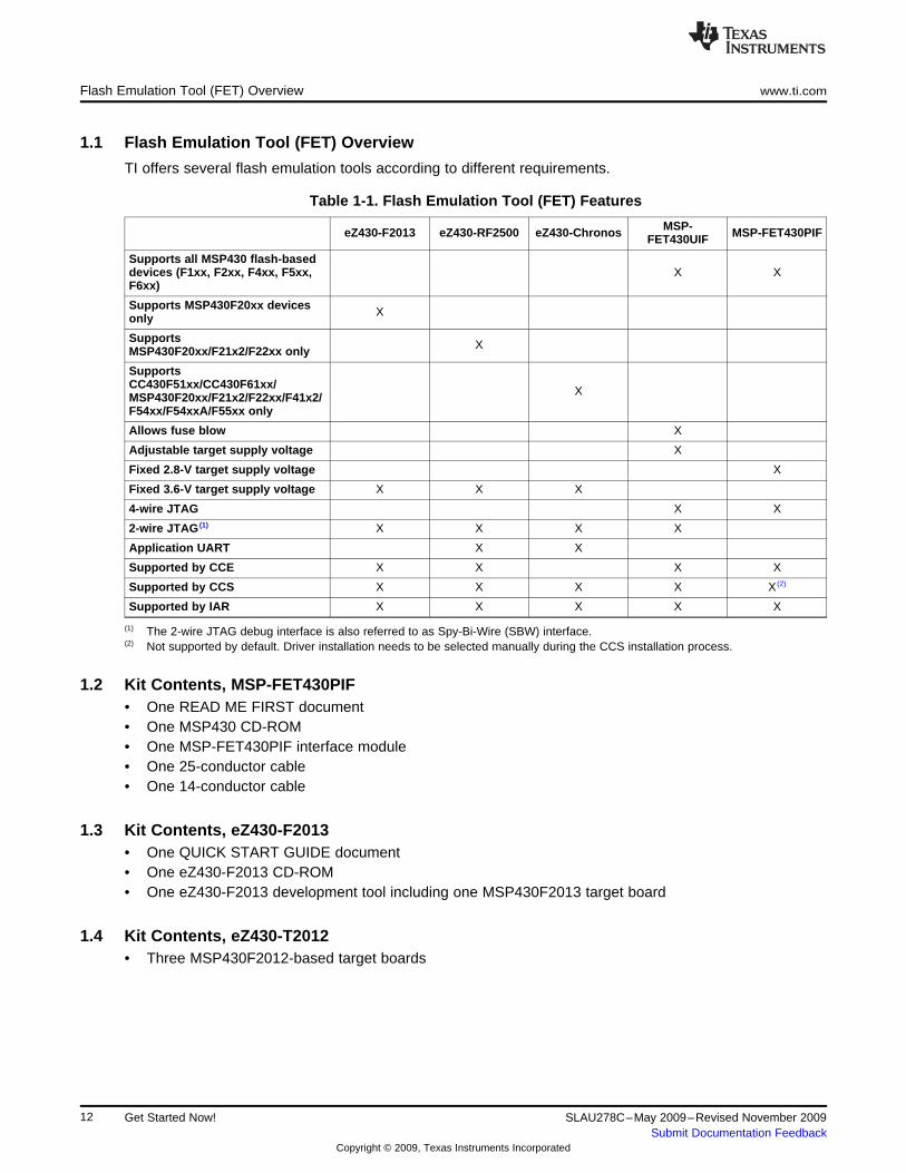
1.1 Flash Emulation Tool (FET) Overview
TI offers several flash emulation tools according to different requirements.
Table 1-1. Flash Emulation Tool (FET) Features
MSP-eZ430-F2013 eZ430-RF2500 eZ430-Chronos MSP-FET430PIFFET430UIF
Supports all MSP430 flash-baseddevices (F1xx, F2xx, F4xx, F5xx, X XF6xx)
Supports MSP430F20xx devices Xonly
Supports XMSP430F20xx/F21x2/F22xx only
SupportsCC430F51xx/CC430F61xx/ XMSP430F20xx/F21x2/F22xx/F41x2/F54xx/F54xxA/F55xx only
Allows fuse blow X
Adjustable target supply voltage X
Fixed 2.8-V target supply voltage X
Fixed 3.6-V target supply voltage X X X
4-wire JTAG X X
2-wire JTAG (1) X X X X
Application UART X X
Supported by CCE X X X X
Supported by CCS X X X X X (2)
Supported by IAR X X X X X
(1) The 2-wire JTAG debug interface is also referred to as Spy-Bi-Wire (SBW) interface.(2) Not supported by default. Driver installation needs to be selected manually during the CCS installation process.
1.2 Kit Contents, MSP-FET430PIF• One READ ME FIRST document• One MSP430 CD-ROM• One MSP-FET430PIF interface module• One 25-conductor cable• One 14-conductor cable
1.3 Kit Contents, eZ430-F2013• One QUICK START GUIDE document• One eZ430-F2013 CD-ROM• One eZ430-F2013 development tool including one MSP430F2013 target board
1.4 Kit Contents, eZ430-T2012• Three MSP430F2012-based target boards
12 Get Started Now! SLAU278C–May 2009–Revised November 2009Submit Documentation Feedback
Copyright © 2009, Texas Instruments Incorporated
www.ti.com Kit Contents, eZ430-RF2500
1.5 Kit Contents, eZ430-RF2500• One QUICK START GUIDE document• One eZ430-RF2500 CD-ROM• One eZ430-RF2500 development tool including one MSP430F2274/CC2500 target board• One eZ430-RF2500T target board• One AAA battery pack with expansion board (batteries included)
1.6 Kit Contents, eZ430-RF2500T• One eZ430-RF2500T target board• One AAA battery pack with expansion board (batteries included)
1.7 Kit Contents, eZ430-RF2500-SEH• One MSP430 development tool CD containing documentation and development software• One eZ430-RF USB debugging interface• Two eZ430-RF2500T wireless target boards• One SEH-01 solar energy harvester board• One AAA battery pack with expansion board (batteries included)
1.8 Kit Contents, eZ430-Chronos-xxx
'433, '868, '915• One QUICK START GUIDE document• One eZ430-Chronos CD-ROM• One ez430-Chronos emulator• One screwdriver• Two spare screws
eZ430-Chronos-433:– One 433-MHz eZ430-Chronos watch (battery included)– One 433-MHz eZ430-Chronos access pointeZ430-Chronos-868:– One 868-MHz eZ430-Chronos watch (battery included)– One 868-MHz eZ430-Chronos access pointeZ430-Chronos-915:– One 915-MHz eZ430-Chronos watch (battery included)– One 915-MHz eZ430-Chronos access point
1.9 Kit Contents, MSP-FET430UIF• One READ ME FIRST document• One MSP430 CD-ROM• One MSP-FET430UIF interface module• One USB cable• One 14-conductor cable
13SLAU278C–May 2009–Revised November 2009 Get Started Now!Submit Documentation Feedback
Copyright © 2009, Texas Instruments Incorporated
Kit Contents, MSP-FET430Uxx www.ti.com
1.10 Kit Contents, MSP-FET430Uxx
'U14, 'U28, 'U38, 'U23x0, 'U48, 'U64, 'U64A, 'U80, 'U80USB, 'U100, 'U100A, 'U5x100• One READ ME FIRST document• One MSP430 CD-ROM• One MSP-FETP430UIF USB interface module. This is the unit that has a USB B-connector on one end
of the case, and a 2×7-pin male connector on the other end of the case.• One 32.768-kHz crystal• One target socket module
MSP-FET430U14: One MSP-TS430PW14 target socket module. This is the PCB on which is mounteda 14-pin ZIF socket. It fits MSP430F20xx devices in 14-pin PW packages. A 2×7-pin male connector isalso present on the PCB.MSP-FET430U28: One MSP-TS430DW28 or MSP-TS430PW28 target socket module. This is the PCBon which is mounted a 28-pin ZIF socket. It fits MSP430F11xx(A) devices in 20- and 28-pin DW andPW packages. A 2×7-pin male connector is also present on the PCB.MSP-FET430U38: One MSP-TS430DA38 target socket module. This is the PCB on which is mounteda 38-pin ZIF socket. It fits MSP430F22x2 and MSP430F22x4 devices in 38-pin DA packages. A2×7-pin male connector is also present on the PCB.MSP-FET430U23x0: One MSP-TS430QFN23x0 (former name MSP-TS430QFN40) target socketmodule. This is the PCB on which is mounted a 40-pin ZIF socket. It fits MSP430F23x0 devices in40-pin RHA packages. A 2×7-pin male connector is also present on the PCB.MSP-FET430U48: One MSP-TS430DL48 target socket module. This is the PCB on which is mounteda 48-pin ZIF socket. It fits MSP430F42x0 and MSP430FG42x0 devices in 48-pin DL packages. A2×7-pin male connector is also present on the PCB.MSP-FET430U64: One MSP-TS430PM64 target socket module. This is the PCB on which is mounteda 64-pin ZIF socket. It fits MSP430F13x, MSP430F14x, MSP430F14x1, MSP430F15x,MSP430F16x(1), MSP430F23x, MSP430F24x, MSP430F24xx, MSP430F261x, MSP430F41x,MSP430F42x(A), MSP430FE42x(A), MSP430FE42x2, and MSP430FW42x devices in 64-pin PMpackages. A 2×7-pin male connector is also present on the PCB.MSP-FET430U64A: One MSP-TS430PM64A target socket module. This is the PCB on which ismounted a 64-pin ZIF socket. It fits MSP430F41x2 devices in 64-pin PM packages. This tool does notsupport other MSP430 derivatives in the 64-pin PM package. A 2×7-pin male connector is also presenton the PCB.MSP-FET430U80: One MSP-TS430PN80 target socket module. This is the PCB on which is mounteda 80-pin ZIF socket. It fits MSP430F241x, MSP430F261x, MSP430F43x, MSP430F43x1,MSP430FG43x, MSP430F47x, and MSP430FG47x devices in 80-pin PN packages. A 2×7-pin maleconnector is also present on the PCB.MSP-FET430U80USB: One MSP-TS430PN80USB target socket module. This is the PCB on which ismounted a 80-pin ZIF socket. It fits MSP430F552x devices with USB peripheral in 80-pin PNpackages. This tool does not support other MSP430 derivatives in the 80-pin PN package. A 2×7-pinmale connector is also present on the PCB.MSP-FET430U100: One MSP-TS430PZ100 target socket module. This is the PCB on which ismounted a 100-pin ZIF socket. It fits MSP430F43x, MSP430F43x1, MSP430F44x, MSP430FG461x,and MSP430F47xx devices in 100-pin PZ packages. A 2×7-pin male connector is also present on thePCB.MSP-FET430U100A: One MSP-TS430PZ100A target socket module (red PCB). This is the PCB onwhich is mounted a 100-pin ZIF socket. It fits MSP430F471xx devices in 100-pin PZ packages. Thistool does not support other MSP430 derivatives in the 100-pin PZ package. A 2×7-pin male connectoris also present on the PCB.MSP-FET430U5x100: One MSP-TS430PZ5x100 target socket module. This is the PCB on which ismounted a 100-pin ZIF socket. It fits MSP430F54xx devices in 100-pin PZ packages. This tool doesnot support other MSP430 derivatives in the 100-pin PZ package. A 2×7-pin male connector is alsopresent on the PCB.
• One USB cable• One 14-conductor cable• Four or eight headers
14 Get Started Now! SLAU278C–May 2009–Revised November 2009Submit Documentation Feedback
Copyright © 2009, Texas Instruments Incorporated
www.ti.com Kit Contents, FET430F6137RF900
MSP-FET430U14: Four PCB 1×7-pin headers (two male and two female)MSP-FET430U28: Four PCB 1×14-pin headers (two male and two female)MSP-FET430U38: Four PCB 1×19-pin headers (two male and two female)MSP-FET430U23x0: Eight PCB 1×10-pin headers (four male and four female)MSP-FET430U48: Four PCB 2×24-pin headers (two male and two female)MSP-FET430U64: Eight PCB 1×16-pin headers (four male and four female)MSP-FET430U64A: Eight PCB 1×16-pin headers (four male and four female)MSP-FET430U80: Eight PCB 1×20-pin headers (four male and four female)MSP-FET430U80USB: Eight PCB 1×20-pin headers (four male and four female)MSP-FET430U100: Eight PCB 1×25-pin headers (four male and four female)MSP-FET430U100A: Eight PCB 1×25-pin headers (four male and four female)MSP-FET430U5x100: Eight PCB 1×25-pin headers (four male and four female)
• One small box containing two or four MSP430 device samplesMSP-FET430U14: MSP430F2013IPWMSP-FET430U28: MSP430F123IDW and/or MSP430F1232IDW or MSP430F2132IPWMSP-FET430U38: MSP430F2274IDAMSP-FET430U23x0: MSP430F2370IRHAMSP-FET430U48: MSP430F4270IDLMSP-FET430U64: MSP430F417IPM and MSP430F169IPMMSP-FET430U64A: MSP430F4152IPMMSP-FET430U80: MSP430FG439IPNMSP-FET430U80USB: MSP430F5529IPNMSP-FET430U100: MSP430FG4619IPZMSP-FET430U100A: MSP430F47197IPZMSP-FET430U5x100: MSP430F5438IPZConsult the device data sheets for device specifications. Device errata can be found in the respectivedevice product folder on the web provided as a PDF document. Depending on the device, errata mayalso be found in the device bug database at www.ti.com/sc/cgi-bin/buglist.cgi.
1.11 Kit Contents, FET430F6137RF900• One READ ME FIRST document• One legal notice• One MSP430 CD-ROM• One MSP-FET430UIF interface module• Two EM430F6137RF900 target socket modules. This is the PCB on which is mounted a 64-pin socket.
It fits CC430F612x, CC430F613x, and CC430F513x devices in 64-pin RGC packages. A 2×7-pin maleconnector is also present on the PCB.
• Two CC430EM battery packs• Four AAA batteries• Two 868-/915-MHz antennas• Two 32-kHz crystals• 18 PCB 2x4-pin headers• One USB cable
15SLAU278C–May 2009–Revised November 2009 Get Started Now!Submit Documentation Feedback
Copyright © 2009, Texas Instruments Incorporated
Kit Contents, MSP-TS430xx www.ti.com
1.12 Kit Contents, MSP-TS430xx
'PW14, 'PW28, 'DA38, 'DL48, 'DW28, 'PM64, 'PM64A, 'PN80, 'PN80USB, 'PZ100, 'PZ100A, 'PZ5x100• One READ ME FIRST document• One MSP430 CD-ROM• One 32.768-kHz crystal• One target socket module
MSP-TS430PW14: One MSP-TS430PW14 target socket module. This is the PCB on which is mounteda 14-pin ZIF socket. It fits MSP430F20xx devices in 14-pin PW packages. A 2×7-pin male connector isalso present on the PCB.MSP-TS430DW28: One MSP-TS430DW28 target socket module. This is the PCB on which ismounted a 28-pin ZIF socket. It fits MSP430F11xx(A) devices in 28-pin DW packages. A 2×7-pin maleconnector is also present on the PCB.MSP-TS430PW28: One MSP-TS430PW28 target socket module. This is the PCB on which is mounteda 28-pin ZIF socket. It fits MSP430F11xx(A) devices in 28-pin PW packages. A 2×7-pin maleconnector is also present on the PCB.MSP-TS430DA38: One MSP-TS430DA38 target socket module. This is the PCB on which is mounteda 38-pin ZIF socket. It fits MSP430F22x2 and MSP430F22x4 devices in 38-pin DA packages. A2×7-pin male connector is also present on the PCB.MSP-TS430DL48:One MSP-TS430DL48 target socket module. This is the PCB on which is mounted a48-pin ZIF socket. It fits MSP430F42x0 and MSP430FG42x0 devices in 48-pin DL packages. A2×7-pin male connector is also present on the PCB.MSP-TS430PM64: One MSP-TS430PM64 target socket module. This is the PCB on which is mounteda 64-pin ZIF socket. It fits MSP430F13x, MSP430F14x, MSP430F14x1, MSP430F15x,MSP430F16x(1), MSP430F23x, MSP430F24x, MSP430F24xx, MSP430F261x, MSP430F41x,MSP430F42x(A), MSP430FE42x(A), MSP430FE42x2, and MSP430FW42x devices in 64-pin PMpackages, except the MSP430F41x2. A 2×7-pin male connector is also present on the PCB.MSP-TS430PM64A: One MSP-TS430PM64A target socket module. This is the PCB on which ismounted a 64-pin ZIF socket. It fits MSP430F41x2 devices in 64-pin PM packages. This tool does notsupport other MSP430 derivatives in the 64-pin PM package. A 2×7-pin male connector is also presenton the PCB.MSP-TS430PN80: One MSP-TS430PN80 target socket module. This is the PCB on which is mountedan 80-pin ZIF socket. It fits MSP430F241x, MSP430F261x, MSP430F43x, MSP430F43x1,MSP430FG43x, MSP430F47x, and MSP430FG47x devices in 80-pin PN packages. A 2×7-pin maleconnector is also present on the PCB.MSP-TS430PN80USB: One MSP-TS430PN80USB target socket module. This is the PCB on which ismounted an 80-pin ZIF socket. It fits the MSP430F552x and MSP430F551x devices in 80-pin PNpackages. This tool does not support other MSP430 devices in the 80-pin PN package.MSP-TS430PZ100: One MSP-TS430PZ100 target socket module (red PCB). This is the PCB on whichis mounted a 100-pin ZIF socket. It fits MSP430F43x, MSP430F43x1, MSP430F44x, MSP430FG461x,and MSP430F47xx devices in 100-pin PZ packages. A 2×7-pin male connector is also present on thePCB.MSP-TS430PZ100A: One MSP-TS430PZ100A target socket module (red PCB). This is the PCB onwhich is mounted a 100-pin ZIF socket. It fits MSP430F471xx devices in 100-pin PZ packages. A2×7-pin male connector is also present on the PCB.MSP-TS430U5x100: One MSP-TS430PZ5x100 target socket module. This is the PCB on which ismounted a 100-pin ZIF socket. It fits all MSP430F54xx devices in 100-pin PZ packages. A 2×7-pinmale connector is also present on the PCB.
• PCB headersMSP-TS430PW14: Four PCB 1×7-pin headers (two male and two female)MSP-TS430DW28: Eight PCB 1×16-pin headers (four male and four female)MSP-TS430PW28: Four PCB 1×14-pin headers (two male and two female)MSP-TS430DA38: Four PCB 1×19-pin headers (two male and two female)MSP-TS430DL48: Four PCB 2×24-pin headers (two male and two female)MSP-TS430PM64: Eight PCB 1×16-pin headers (four male and four female)
16 Get Started Now! SLAU278C–May 2009–Revised November 2009Submit Documentation Feedback
Copyright © 2009, Texas Instruments Incorporated
www.ti.com Kit Contents, EM430F6137RF900
MSP-TS430PM64A: Eight PCB 1×16-pin headers (four male and four female)MSP-TS430PN80: Eight PCB 1×16-pin headers (four male and four female)MSP-TS430PN80USB: Eight PCB 1×16-pin headers (four male and four female)MSP-TS430PZ100A: Eight PCB 1×25-pin headers (four male and four female)MSP-TS430PZ5x100: Eight PCB 1×25-pin headers (four male and four female)
• One small box containing two MSP430 device samplesMSP-TS430PW14: MSP430F2013IPWMSP-TS430DW28: MSP430F1232IDWRMSP-TS430PW28: MSP430F2132IPWMSP-TS430DA38: MSP430F2274IDAMSP-TS430DL48: MSP430F4270IDLMSP-TS430PM64: MSP430F417IPM and MSP430F169IPMMSP-TS430PM64A: MSP430F4152IPMMSP-TS430PN80: MSP430FG439IPNMSP-TS430PN80USB: MSP430F5529IPNMSP-TS430PZ100A: MSP430F47197IPZMSP-TS430PZ5x100: MSP430F5438IPZConsult the device data sheets for device specifications. Device errata can be found in the respectivedevice product folder on the web provided as a PDF document. Depending on the device, errata mayalso be found in the device bug database at www.ti.com/sc/cgi-bin/buglist.cgi.
1.13 Kit Contents, EM430F6137RF900• One READ ME FIRST document• One legal notice• One MSP430 CD-ROM• Two EM430F6137RF900 target socket modules. This is the PCB on which is mounted a 64-pin socket.
It fits CC430F612x, CC430F613x, and CC430F513x devices in 64-pin RGC packages. A 2×7-pin maleconnector is also present on the PCB.
• Two CC430EM battery packs• Four AAA batteries• Two 868-/915-MHz antennas• Two 32-kHz crystals• 18 PCB 2×4-pin headers
1.14 Hardware Installation, MSP-FET430PIF
Follow these steps to install the hardware for the MSP-FET430PIF tools:
1. Use the 25-conductor cable to connect the FET interface module to the parallel port of the PC. Thenecessary driver for accessing the PC parallel port is installed automatically during CCE or IAREmbedded Workbench installation. Note that a restart is required after the CCE or IAR EmbeddedWorkbench installation for the driver to become active.
2. Use the 14-conductor cable to connect the parallel-port debug interface module to a target board, suchas an MSP-TS430xxx target socket module. Module schematics and PCBs are shown in .
17SLAU278C–May 2009–Revised November 2009 Get Started Now!Submit Documentation Feedback
Copyright © 2009, Texas Instruments Incorporated
Hardware Installation, MSP-FET430UIF www.ti.com
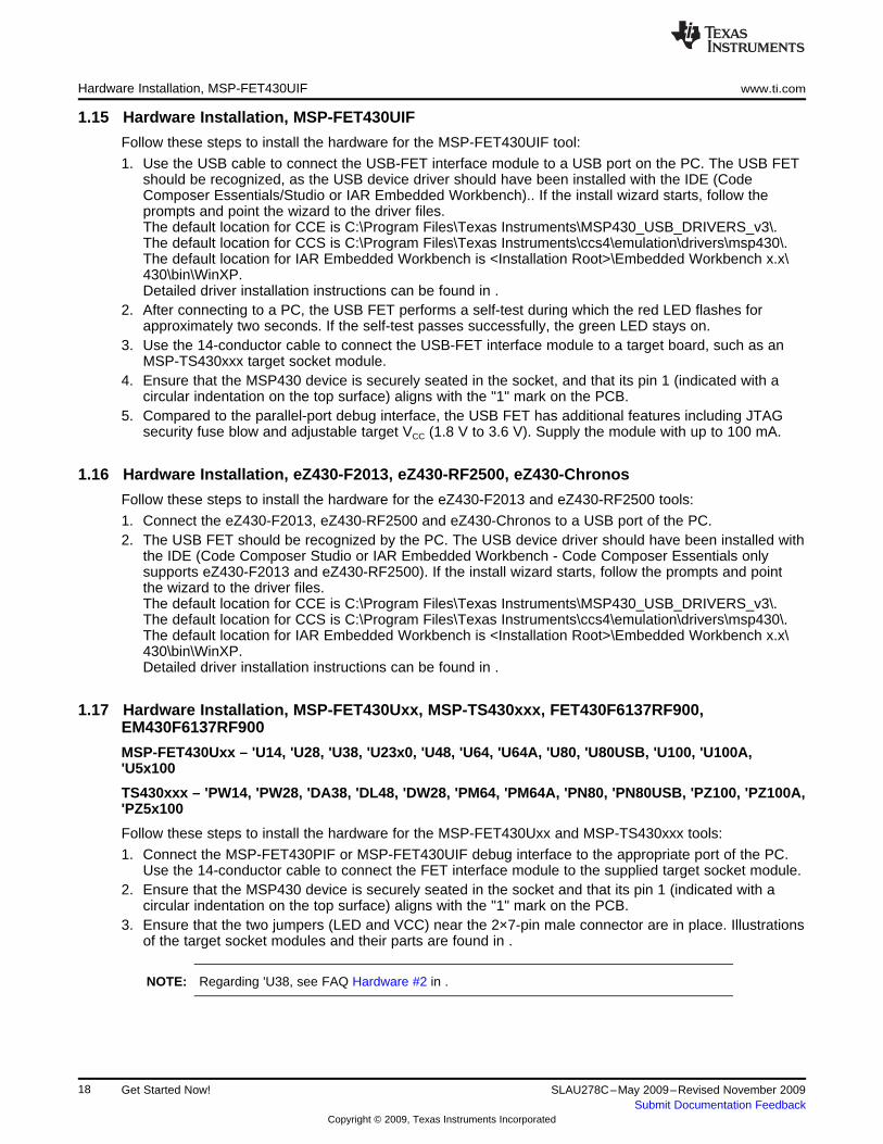
1.15 Hardware Installation, MSP-FET430UIF
Follow these steps to install the hardware for the MSP-FET430UIF tool:
1. Use the USB cable to connect the USB-FET interface module to a USB port on the PC. The USB FETshould be recognized, as the USB device driver should have been installed with the IDE (CodeComposer Essentials/Studio or IAR Embedded Workbench).. If the install wizard starts, follow theprompts and point the wizard to the driver files.The default location for CCE is C:\Program Files\Texas Instruments\MSP430_USB_DRIVERS_v3\.The default location for CCS is C:\Program Files\Texas Instruments\ccs4\emulation\drivers\msp430\.The default location for IAR Embedded Workbench is <Installation Root>\Embedded Workbench x.x\430\bin\WinXP.Detailed driver installation instructions can be found in .
2. After connecting to a PC, the USB FET performs a self-test during which the red LED flashes forapproximately two seconds. If the self-test passes successfully, the green LED stays on.
3. Use the 14-conductor cable to connect the USB-FET interface module to a target board, such as anMSP-TS430xxx target socket module.
4. Ensure that the MSP430 device is securely seated in the socket, and that its pin 1 (indicated with acircular indentation on the top surface) aligns with the "1" mark on the PCB.
5. Compared to the parallel-port debug interface, the USB FET has additional features including JTAGsecurity fuse blow and adjustable target VCC (1.8 V to 3.6 V). Supply the module with up to 100 mA.
1.16 Hardware Installation, eZ430-F2013, eZ430-RF2500, eZ430-Chronos
Follow these steps to install the hardware for the eZ430-F2013 and eZ430-RF2500 tools:
1. Connect the eZ430-F2013, eZ430-RF2500 and eZ430-Chronos to a USB port of the PC.2. The USB FET should be recognized by the PC. The USB device driver should have been installed with
the IDE (Code Composer Studio or IAR Embedded Workbench - Code Composer Essentials onlysupports eZ430-F2013 and eZ430-RF2500). If the install wizard starts, follow the prompts and pointthe wizard to the driver files.The default location for CCE is C:\Program Files\Texas Instruments\MSP430_USB_DRIVERS_v3\.The default location for CCS is C:\Program Files\Texas Instruments\ccs4\emulation\drivers\msp430\.The default location for IAR Embedded Workbench is <Installation Root>\Embedded Workbench x.x\430\bin\WinXP.Detailed driver installation instructions can be found in .
1.17 Hardware Installation, MSP-FET430Uxx, MSP-TS430xxx, FET430F6137RF900,EM430F6137RF900
MSP-FET430Uxx – 'U14, 'U28, 'U38, 'U23x0, 'U48, 'U64, 'U64A, 'U80, 'U80USB, 'U100, 'U100A,'U5x100
TS430xxx – 'PW14, 'PW28, 'DA38, 'DL48, 'DW28, 'PM64, 'PM64A, 'PN80, 'PN80USB, 'PZ100, 'PZ100A,'PZ5x100
Follow these steps to install the hardware for the MSP-FET430Uxx and MSP-TS430xxx tools:
1. Connect the MSP-FET430PIF or MSP-FET430UIF debug interface to the appropriate port of the PC.Use the 14-conductor cable to connect the FET interface module to the supplied target socket module.
2. Ensure that the MSP430 device is securely seated in the socket and that its pin 1 (indicated with acircular indentation on the top surface) aligns with the "1" mark on the PCB.
3. Ensure that the two jumpers (LED and VCC) near the 2×7-pin male connector are in place. Illustrationsof the target socket modules and their parts are found in .
NOTE: Regarding 'U38, see FAQ Hardware #2 in .
18 Get Started Now! SLAU278C–May 2009–Revised November 2009Submit Documentation Feedback
Copyright © 2009, Texas Instruments Incorporated
www.ti.com Important MSP430 Documents on the CD-ROM and Web
1.18 Important MSP430 Documents on the CD-ROM and Web
The primary sources of MSP430 information are the device-specific data sheet and user's guide. The mostup-to-date versions of these documents that are available at the time of production are provided on theCD-ROM included with this tool. The MSP430 web site (www.ti.com/msp430) contains the most recentversion of these documents.
PDF documents describing the CCS tools (CCS IDE, the assembler, the C compiler, the linker, and thelibrarian) are in the msp430\documentation folder. A Code Composer Studio specific Wiki page (FAQ) isavailable, and the Texas Instruments E2E Community support forums for the MSP430 and CodeComposer Studio v4 provide additional help besides the product help and Welcome page.
PDF documents describing the IAR tools (Workbench/C-SPY, the assembler, the C compiler, the linker,and the librarian) are in the common\doc and 430\doc folders. Supplements to the documents (i.e., thelatest information) are available in HTML format in the same directories. 430\doc\readme_start.htmprovides a convenient starting point for navigating the IAR documentation.
19SLAU278C–May 2009–Revised November 2009 Get Started Now!Submit Documentation Feedback
Copyright © 2009, Texas Instruments Incorporated

20 Get Started Now! SLAU278C–May 2009–Revised November 2009Submit Documentation Feedback
Copyright © 2009, Texas Instruments Incorporated
Chapter 2SLAU278C–May 2009–Revised November 2009
Design Considerations for In-Circuit Programming
This chapter presents signal requirements for in-circuit programming of the MSP430.
Topic ........................................................................................................................... Page
2.1 Signal Connections for In-System Programming and Debugging ............................ 222.2 External Power .................................................................................................. 252.3 Bootstrap Loader .............................................................................................. 25
21SLAU278C–May 2009–Revised November 2009 Design Considerations for In-Circuit ProgrammingSubmit Documentation Feedback
Copyright © 2009, Texas Instruments Incorporated
Signal Connections for In-System Programming and Debugging www.ti.com
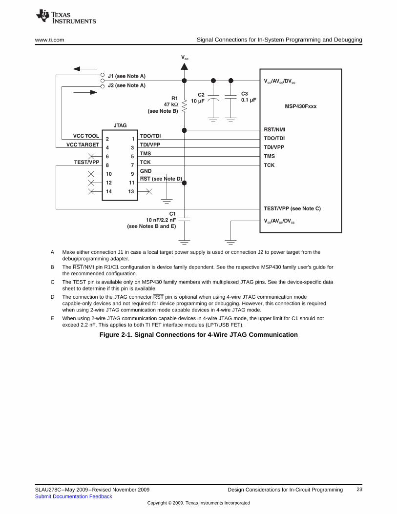
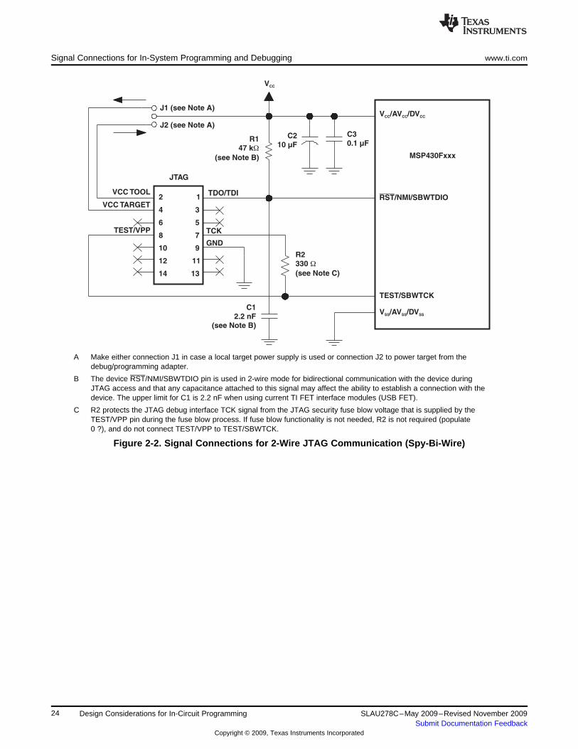
2.1 Signal Connections for In-System Programming and Debugging
MSP-FET430PIF, MSP-FET430UIF, MSP-GANG430, MSP-PRGS430
With the proper connections, the debugger and an FET hardware JTAG interface (such as theMSP-FET430PIF and MSP-FET430UIF) can be used to program and debug code on the target board. Inaddition, the connections also support the MSP-GANG430 or MSP-PRGS430 production programmers,thus providing an easy way to program prototype boards, if desired.
Figure 2-1 shows the connections between the 14-pin FET interface module connector and the targetdevice required to support in-system programming and debugging for 4-wire JTAG communication.Figure 2-2 shows the connections for 2-wire JTAG mode (Spy-Bi-Wire). While 4-wire JTAG mode issupported on all MSP430 devices, 2-wire JTAG mode is available on selected devices only. See the CCEfor MSP430 User's Guide (SLAU157) or IAR for MSP430 User's Guide (SLAU138) for information onwhich interface method can be used on which device.
The connections for the FET interface module and the MSP-GANG430 or MSP-PRGS430 are identical.Both the FET interface module and MSP-GANG430 can supply VCC to the target board (via pin 2). Inaddition, the FET interface module and MSP-GANG430 have a VCC-sense feature that, if used, requiresan alternate connection (pin 4 instead of pin 2). The VCC-sense feature senses the local VCC present on thetarget board (i.e., a battery or other local power supply) and adjusts the output signals accordingly. If thetarget board is to be powered by a local VCC, then the connection to pin 4 on the JTAG should be made,and not the connection to pin 2. This utilizes the VCC-sense feature and prevents any contention that mightoccur if the local on-board VCC were connected to the VCC supplied from the FET interface module or theMSP-GANG430. If the VCC-sense feature is not necessary (i.e., the target board is to be powered from theFET interface module or the GANG430) the VCC connection is made to pin 2 on the JTAG header and noconnection is made to pin 4. Figure 2-1 and Figure 2-2 show a jumper block that supports both scenariosof supplying VCC to the target board. If this flexibility is not required, the desired VCC connections may behard-wired eliminating the jumper block. Pins 2 and 4 must not be connected simultaneously.
Note that in 4-wire JTAG communication mode (see Figure 2-1), the connection of the target RST signalto the JTAG connector is optional when using devices that support only 4-wire JTAG communicationmode. However, when using devices that support 2-wire JTAG communication mode in 4-wire JTAGmode, the RST connection must be made. The MSP430 development tools and device programmersperform a target reset by issuing a JTAG command to gain control over the device. However, if this isunsuccessful, the RST signal of the JTAG connector may be used by the development tool or deviceprogrammer as an additional way to assert a device reset.
22 Design Considerations for In-Circuit Programming SLAU278C–May 2009–Revised November 2009Submit Documentation Feedback
Copyright © 2009, Texas Instruments Incorporated
1
3
5
7
9
11
13
2
4
6
8
10
12
14
TDO/TDI
TDI/VPP
TMS
TCK
GND
TEST/VPP
JTAG
VCC TOOL
VCC TARGET
J1 (see Note A)
J2 (see Note A)
VCC
R1
47 k
(see Note B)
W
C2
10 µF
C3
0.1 µF
V /AV /DVCCCC CC
RST/NMI
TDO/TDI
TDI/VPP
TMS
TCK
TEST/VPP (see Note C)
V /AV /DVSS SS SS
MSP430Fxxx
C1
10 nF/2.2 nF
(see Notes B and E)
RST (see Note D)
www.ti.com Signal Connections for In-System Programming and Debugging
A Make either connection J1 in case a local target power supply is used or connection J2 to power target from thedebug/programming adapter.
B The RST/NMI pin R1/C1 configuration is device family dependent. See the respective MSP430 family user's guide forthe recommended configuration.
C The TEST pin is available only on MSP430 family members with multiplexed JTAG pins. See the device-specific datasheet to determine if this pin is available.
D The connection to the JTAG connector RST pin is optional when using 4-wire JTAG communication modecapable-only devices and not required for device programming or debugging. However, this connection is requiredwhen using 2-wire JTAG communication mode capable devices in 4-wire JTAG mode.
E When using 2-wire JTAG communication capable devices in 4-wire JTAG mode, the upper limit for C1 should notexceed 2.2 nF. This applies to both TI FET interface modules (LPT/USB FET).
Figure 2-1. Signal Connections for 4-Wire JTAG Communication
23SLAU278C–May 2009–Revised November 2009 Design Considerations for In-Circuit ProgrammingSubmit Documentation Feedback
Copyright © 2009, Texas Instruments Incorporated
TCK
GND
TEST/VPP
VCC TOOL
VCC TARGET
J2 (see Note A)
VCC
R1
47 k
(see Note B)
W
C2
10 µF
C3
0.1 µF
V /AV /DVCCCC CC
RST/NMI/SBWTDIO
MSP430Fxxx
C1
2.2 nF
(see Note B)
TEST/SBWTCK
V /AV /DVSS SS SS
J1 (see Note A)
JTAG
TDO/TDI1
3
5
7
9
11
13
2
4
6
8
10
12
14
R2
330
(see Note C)
W
Signal Connections for In-System Programming and Debugging www.ti.com
A Make either connection J1 in case a local target power supply is used or connection J2 to power target from thedebug/programming adapter.
B The device RST/NMI/SBWTDIO pin is used in 2-wire mode for bidirectional communication with the device duringJTAG access and that any capacitance attached to this signal may affect the ability to establish a connection with thedevice. The upper limit for C1 is 2.2 nF when using current TI FET interface modules (USB FET).
C R2 protects the JTAG debug interface TCK signal from the JTAG security fuse blow voltage that is supplied by theTEST/VPP pin during the fuse blow process. If fuse blow functionality is not needed, R2 is not required (populate0 ?), and do not connect TEST/VPP to TEST/SBWTCK.
Figure 2-2. Signal Connections for 2-Wire JTAG Communication (Spy-Bi-Wire)
24 Design Considerations for In-Circuit Programming SLAU278C–May 2009–Revised November 2009Submit Documentation Feedback
Copyright © 2009, Texas Instruments Incorporated
www.ti.com External Power
2.2 External Power
The PC parallel port can source a limited amount of current. Because of the ultra-low-power requirementof the MSP430, a standalone FET does not exceed the available current. However, if additional circuitry isadded to the tool, this current limit could be exceeded. In this case, external power can be supplied to thetool via connections provided on the target socket modules. See the schematics and pictorials of thetarget socket modules in to locate the external power connectors.
The MSP-FET430UIF can supply targets with up to 100 mA through pin 2 of the 14-pin connector. VCC forthe target can be selected between 1.8 V and 5 V in steps of 0.1 V. Alternatively, the target can besupplied externally. In this case, the external voltage should be connected to pin 4 of the 14-pin connector.The MSP-FET430UIF then adjusts the level of the JTAG signals to external VCC automatically. Only pin 2(MSP-FET430UIF supplies target) or pin 4 (target is externally supplied) must be connected; not both atthe same time.
When a target socket module is powered from an external supply, the external supply powers the deviceon the target socket module and any user circuitry connected to the target socket module, and the FETinterface module continues to be powered from the PC via the parallel port. If the externally suppliedvoltage differs from that of the FET interface module, the target socket module must be modified so thatthe externally supplied voltage is routed to the FET interface module (so that it may adjust its outputvoltage levels accordingly). See the target socket module schematics in .
2.3 Bootstrap Loader
The JTAG pins provide access to the flash memory of the MSP430Fxxx devices. On some devices, thesepins are shared with the device port pins, and this sharing of pins can complicate a design (or sharing maynot be possible). As an alternative to using the JTAG pins, most MSP430Fxxx devices contain a program(a "bootstrap loader") that permits the flash memory to be erased and programmed using a reduced set ofsignals. The MSP430 Memory Programming User's Guide (SLAU265) describes this interface. TI does notproduce a BSL tool. However, customers can easily develop their own BSL tools using the information inthe application reports, or BSL tools can be purchased from third parties. See the MSP430 web site forthe application reports and a list of MSP430 third-party tool developers.
TI suggests that MSP430Fxxx customers design their circuits with the BSL in mind (i.e., TI suggestsproviding access to these signals via, for example, a header).
See FAQ Hardware #11 for a second alternative to sharing the JTAG and port pins.
25SLAU278C–May 2009–Revised November 2009 Design Considerations for In-Circuit ProgrammingSubmit Documentation Feedback
Copyright © 2009, Texas Instruments Incorporated

26 Design Considerations for In-Circuit Programming SLAU278C–May 2009–Revised November 2009Submit Documentation Feedback
Copyright © 2009, Texas Instruments Incorporated
Appendix ASLAU278C–May 2009–Revised November 2009
Frequently Asked Questions and Known Issues
This appendix presents solutions to frequently asked questions regarding the MSP-FET430 hardware.
Topic ........................................................................................................................... Page
A.1 Hardware FAQs ................................................................................................. 28A.2 Known Issues ................................................................................................... 30
27SLAU278C–May 2009–Revised November 2009 Frequently Asked Questions and Known IssuesSubmit Documentation Feedback
Copyright © 2009, Texas Instruments Incorporated
Hardware FAQs www.ti.com
A.1 Hardware FAQs1. The state of the device (CPU registers, RAM memory, etc.) is undefined following a reset.
Exceptions to the above statement are that the PC is loaded with the word at 0xFFFE (i.e., the resetvector), the status register is cleared, and the peripheral registers (SFRs) are initialized as documentedin the device family user's guides. The CCE/CCS debugger and C-SPY reset the device afterprogramming it.
2. MSP430F22xx Target Socket Module (MSP-TS430DA38) – Important InformationDue to the large capacitive coupling introduced by the device socket between the adjacent signalsXIN/P2.6 (socket pin 6) and RST/SBWTDIO (socket pin 7), in-system debugging can disturb theLFXT1 low-frequency crystal oscillator operation (ACLK). This behavior applies only to the Spy-Bi-Wire(2-wire) JTAG configuration and only to the period while a debug session is active.Workarounds:
• Use the 4-wire JTAG mode debug configuration instead of the Spy-Bi-Wire (2-wire) JTAGconfiguration. This can be achieved by placing jumpers JP4 through JP9 accordingly.
• Use the debugger option "Run Free" that can be selected from the Advanced Run drop-downmenu (at top of Debug View). This prevents the debugger from accessing the MSP430 while theapplication is running. Note that, in this mode, a manual halt is required to see if a breakpoint washit. See the IDE documentation for more information on this feature.
• Use an external clock source to drive XIN directly.3. With current interface hardware and software, there is a weakness when adapting target boards
that are powered externally. This leads to an accidental fuse check in the MSP430. This is valid forPIF and UIF but is mainly seen on UIF. A solution is being developed.Workarounds:
• Connect RST/NMI pin to JTAG header (pin 11), LPT/USB tools are able to pull the RST line, whichalso resets the device internal fuse logic.
• Use the debugger option "Release JTAG On Go" that can be selected from the IDE drop-downmenu. This prevents the debugger from accessing the MSP430 while the application is running.Note that in this mode, a manual halt is required to see if a breakpoint was hit. See the IDEdocumentation for more information on this feature.
• Use an external clock source to drive XIN directly.4. The 14-conductor cable connecting the FET interface module and the target socket module must not
exceed 8 inches (20 centimeters) in length.5. The signal assignment on the 14-conductor cable is identical for the parallel port interface and the
USB FET.6. To utilize the on-chip ADC voltage references, C6 (10 ?F, 6.3 V, low leakage) must be installed on
the target socket module.7. To utilize the charge pump on the devices with LCD+ Module, C4 (10 ?F, low leakage) must be
installed on the target socket module.8. Crystals/resonators Q1 and Q2 (if applicable) are not provided on the target socket module. For
MSP430 devices that contain user-selectable loading capacitors, the effective capacitance is theselected capacitance plus 3 pF (pad capacitance) divided by two.
9. Crystals/resonators have no effect upon the operation of the tool and the CCE/CCS debugger orC-SPY (as any required clocking/timing is derived from the internal DCO/FLL).
10. On 20-pin and 28-pin devices with multiplexed port/JTAG pins (P1.4 to P1.7), to use these pin intheir port capacity:For CCE/CCS: "Run Free" (in Run pull-down menu at top of Debug View) must be selected.For C-SPY: "Release JTAG On Go" must be selected.
11. As an alternative to sharing the JTAG and port pins (on 20 and 28 pin devices), consider usingan MSP430 device that is a "superset" of the smaller device. A very powerful feature of theMSP430 is that the family members are code and architecturally compatible, so code developed onone device (for example, one without shared JTAG and port pins) ports effortlessly to another(assuming an equivalent set of peripherals).
28 Frequently Asked Questions and Known Issues SLAU278C–May 2009–Revised November 2009Submit Documentation Feedback
Copyright © 2009, Texas Instruments Incorporated
www.ti.com Hardware FAQs
12. Information memory may not be blank (erased to 0xFF) when the device is delivered from TI.Customers should erase the information memory before its first use. Main memory of packageddevices is blank when the device is delivered from TI.
13. The device current increases by approximately 10 ?A when a device in low-power mode isstopped [using Halt (CCE/CCS) or Esc (C-SPY)] and then the low-power mode is restored [usingRun (CCE/CCS) or Go (C-SPY)]. This behavior appears to happen on all devices except theMSP430F12x.
14. The following ZIF sockets are used in the FET tools and target socket modules:
• 14-pin device (PW package): Enplas OTS-14-065-01• 28-pin device (DW package): Wells-CTI 652 D028• 28-pin device (PW package): Enplas OTS-28-0.65-01• 38-pin device (DA package): Yamaichi IC189-0382-037• 40-pin device (RHA package): Enplas QFN-40B-0.5-01• 48-pin device (DL package): Yamaichi IC51-0482-1163• 64-pin device (PM package): Yamaichi IC51-0644-807• 80-pin device (PN package): Yamaichi IC201-0804-014• 100-pin device (PZ package): Yamaichi IC201-1004-008Enplas: www.enplas.comWells-CTI: www.wellscti.comYamaichi: www.yamaichi.us
29SLAU278C–May 2009–Revised November 2009 Frequently Asked Questions and Known IssuesSubmit Documentation Feedback
Copyright © 2009, Texas Instruments Incorporated
Known Issues www.ti.com
A.2 Known Issues
MSP-FET430PIF Some PCs do not supply 5 V through the parallel port
Problem Description Device identification problems with modern PCs, because the parallel port often does notdeliver 5 V as was common with earlier hardware.
1. When connected to a laptop, the test signal is clamped to 2.5 V.2. When the external VCC becomes less than 3 V, up to 10 mA is flowing in the adapter
via pin 4 (sense).
Solution Measure the voltage level of the parallel port. If it is too low, provide external 5 V to theVCC pads of the interface. The jumper on a the target socket must be switched toexternal power.
MSP-FET430UIF Current detection algorithm of the UIF firmware
Problem Description If high current is detected, the ICC Monitor algorithm stays in a loop of frequentlyswitching on and off the target power supply. This power switching puts some MSP430devices such as the MSP430F5438 in a state that requires a power cycle to return thedevice to JTAG control.
A side issue is that if the UIF firmware has entered this switch on / switch off loop, it isnot possible to turn off the power supply to the target by calling MSP430_VCC(0). Apower cycle is required to remove the device from this state.
Solution IAR KickStart and Code Composer Essentials that have the MSP430.dll version2.04.00.003 and higher do not show this problem. Update the software development toolto this version or higher to update the MSP-FET430UIF firmware.
30 Frequently Asked Questions and Known Issues SLAU278C–May 2009–Revised November 2009Submit Documentation Feedback
Copyright © 2009, Texas Instruments Incorporated
Appendix BSLAU278C–May 2009–Revised November 2009
Hardware
This appendix contains information relating to the FET hardware, including schematics, PCB pictorials,and bills of materials. All other tools, such as the eZ430 series, are described in separate product-specificuser's guides.
Topic ........................................................................................................................... Page
B.1 MSP-TS430PW14 ............................................................................................... 32B.2 MSP-TS430DW28 ............................................................................................... 35B.3 MSP-TS430PW28 ............................................................................................... 38B.4 MSP-TS430DA38 ............................................................................................... 41B.5 MSP-TS430QFN23x0 .......................................................................................... 44B.6 MSP-TS430DL48 ................................................................................................ 47B.7 MSP-TS430PM64 ............................................................................................... 50B.8 MSP-TS430PM64A ............................................................................................. 53B.9 MSP-TS430PN80 ................................................................................................ 56B.10 MSP-TS430PN80USB ......................................................................................... 59B.11 MSP-TS430PZ100 .............................................................................................. 63B.12 MSP-TS430PZ100A ............................................................................................ 66B.13 MSP-TS430PZ5x100 ........................................................................................... 69B.14 EM430F6137RF900 ............................................................................................ 72B.15 MSP-FET430PIF ................................................................................................ 76B.16 MSP-FET430UIF ................................................................................................ 78
31SLAU278C–May 2009–Revised November 2009 HardwareSubmit Documentation Feedback
Copyright © 2009, Texas Instruments Incorporated
MSP-TS430PW14 www.ti.com
B.1 MSP-TS430PW14
Figure B-1. MSP-TS430PW14 Target Socket Module, Schematic
32 Hardware SLAU278C–May 2009–Revised November 2009Submit Documentation Feedback
Copyright © 2009, Texas Instruments Incorporated
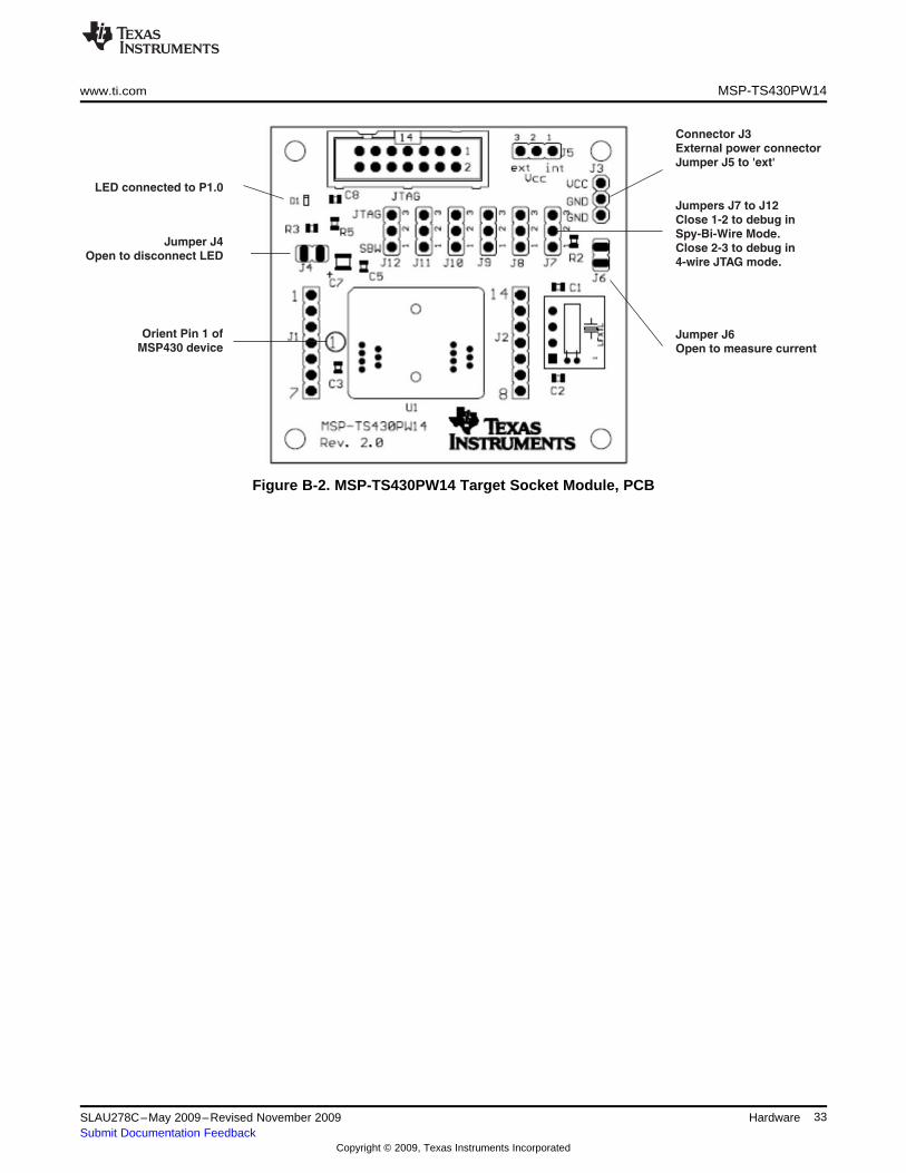
Jumper J4
Open to disconnect LED
Orient Pin 1 of
MSP430 deviceJumper J6
Open to measure current
Connector J3
External power connector
Jumper J5 to 'ext'
LED connected to P1.0
Jumpers J7 to J12
Close 1-2 to debug in
Spy-Bi-Wire Mode.
Close 2-3 to debug in
4-wire JTAG mode.
www.ti.com MSP-TS430PW14
Figure B-2. MSP-TS430PW14 Target Socket Module, PCB
33SLAU278C–May 2009–Revised November 2009 HardwareSubmit Documentation Feedback
Copyright © 2009, Texas Instruments Incorporated
MSP-TS430PW14 www.ti.com
Table B-1. MSP-TS430PW14 Bill of Materials
No. perPosition Ref Des Description DigiKey Part No. CommentBoard
1 C1, C2 0 12pF, SMD0805 DNP
2 C7 1 10uF/10V, Tantal Size B 511-1463-2-ND
3 C3, C5 1 100nF, SMD0805 478-3351-2-ND DNP: C3
4 C8 0 2.2nF, SMD0805 DNP
5 D1 1 green LED, SMD0603 475-1056-2-ND
DNP: Headers and receptacles"SAM1029-07-6 J1, J2 0 7-pin header, TH enclosed with kit. Keep vias free ofNDSAM1213-07-ND" solder: Header: Receptacle
J3, J5, J7, Place jumpers on headers J5, J7, J8,7 J8, J9, J10, 8 3-pin header, male, TH SAM1035-03-ND J9, J10, J11, J12; Pos 1-2J11, J12
8 J4, J6 2 2-pin header, male, TH SAM1035-02-ND Place jumper on header
9 9 Jumper 15-38-1024-ND Place on: J5, J7-J12; Pos 1-2
14-pin connector, male,10 JTAG 1 HRP14H-NDTH
12 Q1 0 Crystal DNP: keep vias free of solder
13 R2, R3 2 330 Ohm, SMD0805 541-330ATR-ND
15 R5 1 47k Ohm, SMD0805 541-47000ATR-ND
16 U1 1 Socket: OTS-14-0.65-01 Manuf.: Enplas
17 PCB 1 56 x 53 mm 2 layers
Adhesive about 6mm width, 2mm e.g., 3M Bumpons Part18 4 Apply to corners at bottom sideplastic feet height No. SJ-5302
19 MSP430 2 MSP430F2013IPW DNP: enclosed with kit, supplied by TI
34 Hardware SLAU278C–May 2009–Revised November 2009Submit Documentation Feedback
Copyright © 2009, Texas Instruments Incorporated
www.ti.com MSP-TS430DW28
B.2 MSP-TS430DW28
Figure B-3. MSP-TS430DW28 Target Socket Module, Schematic
35SLAU278C–May 2009–Revised November 2009 HardwareSubmit Documentation Feedback
Copyright © 2009, Texas Instruments Incorporated
Jumper J4
Open to disconnect LED
Orient Pin 1 of
MSP430 device
Jumper J5
Open to measure current
Connector J3
External power connector
Remove R8 and jumper R9
LED connected to P1.0
MSP-TS430DW28 www.ti.com
Figure B-4. MSP-TS430DW28 Target Socket Module, PCB
36 Hardware SLAU278C–May 2009–Revised November 2009Submit Documentation Feedback
Copyright © 2009, Texas Instruments Incorporated
www.ti.com MSP-TS430DW28
Table B-2. MSP-TS430DW28 Bill of Materials
No. perPosition Ref Des Description DigiKey Part No. CommentBoard
DNP: C1, C2, Cover holes while1 C1, C2 0 12pF, SMD0805 soldering
2 C5 1 100nF, SMD0805
3 C7 1 10uF/10V Tantal Elko B
4 C8 1 10nF SMD0805
5 D1 1 LED3 T1 3mm yellow RS: 228-4991
6 Q1 0 QUARZ3, Crystal DNP: Cover holes while soldering
DNP: Headers and receptacles7 J1, J2 2 14-pin header, TH male enclosed with kit.Keep vias free of
solder.: Header: Receptacle
DNP: Headers and receptacles14-pin header, TH7.1 2 enclosed with kit.Keep vias free offemale solder.: Header: Receptacle
8 J3 1 3-Pin Connector, male
9 J4, J5 2 2-Pin Connector, male With jumper
10 BOOTST 0 ML10, 10-Pin Conn., m RS: 482-115 DNP, Cover holes while soldering
11 JTAG 1 ML14, 14-Pin Conn., m RS: 482-121
R1, R2,R6, R7,12 4 0R, SMD0805 DNP: R1, R2, R9, R10R8,R9,
R10, R11
13 R3 1 560R, SMD0805
14 R5 1 47K, SMD0805
Yamaichi:15 U1 1 SOP28DW socket IC189-0282-042
16 U2 0 TSSOP DNP
37SLAU278C–May 2009–Revised November 2009 HardwareSubmit Documentation Feedback
Copyright © 2009, Texas Instruments Incorporated
MSP-TS430PW28 www.ti.com
B.3 MSP-TS430PW28
Figure B-5. MSP-TS430PW28 Target Socket Module, Schematic
38 Hardware SLAU278C–May 2009–Revised November 2009Submit Documentation Feedback
Copyright © 2009, Texas Instruments Incorporated
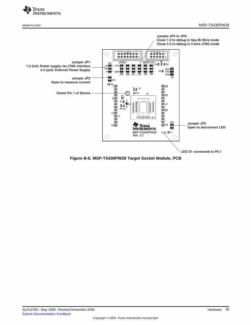
Jumper JP2
Open to measure current
Jumper JP3
Open to disconnect LED
LED D1 connected to P5.1
Jumper JP1
1-2 (int): Power supply via JTAG interface
2-3 (ext): External Power Supply
Jumper JP4 to JP9:
Close 1-2 to debug in Spy-Bi-Wire mode
Close 2-3 to debug in 4-wire JTAG mode
Orient Pin 1 of Device
www.ti.com MSP-TS430PW28
Figure B-6. MSP-TS430PW28 Target Socket Module, PCB
39SLAU278C–May 2009–Revised November 2009 HardwareSubmit Documentation Feedback
Copyright © 2009, Texas Instruments Incorporated
MSP-TS430PW28 www.ti.com
Table B-3. MSP-TS430PW28 Bill of Materials (1)
No. perPos. Ref Des Description DigiKey Part No. CommentBoard
DNP: C1, C2 , Cover holes1 C1, C2 0 12pF, SMD0805 while soldering
2 C3 1 10uF/10V Tantal Elko B
3 C4 1 100nF, SMD0805
4 C5 0 2.2nF, SMD0805 DNP
5 D1 1 LED green SMD0603
DNP: Cover holes and6 Q1 0 QUARZ3, Crystal neighboring holes while
soldering
DNP: Headers andreceptacles enclosed with
7 J1, J2 2 14-pin header, TH male kit.Keep vias free ofsolder.: Header:Receptacle
DNP: headers andreceptacles enclosed with
7.1 2 14-pin header, TH female kit.Keep vias free ofsolder.: Header:Receptacle
8 J5, IP1 1 3-Pin Connector , male
JP1, JP4,JP5, JP6,8a 7 3-Pin Connector , male Jumper on Pos 1-2JP7, JP8,
JP9
9 JP2, JP3 2 2-Pin Connector , male with Jumper
DNP: Cover holes while10 BOOTST 0 ML10, 10-Pin Conn. , m RS: 482-115 soldering
11 JTAG 1 ML14, 14-Pin Conn. , m RS: 482-121
12 R1, R7 2 330R, SMD0805
R2, R3, R5,12 0 0R, SMD0805 DNPR6
14 R4 1 47K, SMD0805
15 U1 1 SOP28PW socket Enplas: OTS-28-0.65-01
(1) PCB 66 x 79 mm, two layers; Rubber stand off, four pieces
40 Hardware SLAU278C–May 2009–Revised November 2009Submit Documentation Feedback
Copyright © 2009, Texas Instruments Incorporated
www.ti.com MSP-TS430DA38
B.4 MSP-TS430DA38
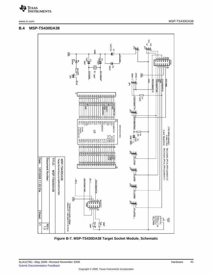
Figure B-7. MSP-TS430DA38 Target Socket Module, Schematic
41SLAU278C–May 2009–Revised November 2009 HardwareSubmit Documentation Feedback
Copyright © 2009, Texas Instruments Incorporated
Orient pin 1 of
MSP430 device
LED connected to P1.0
Connector J3
External power connector
Jumper JP1 to 'ext'
Jumper JP3
Open to disconnect LED
Jumper JP2
Open to measure current
Jumpers JP4 to JP9
Close 1-2 to debug in
Spy-Bi-Wire Mode,
Close 2-3 to debug in
4-wire JTAG Mode
MSP-TS430DA38 www.ti.com
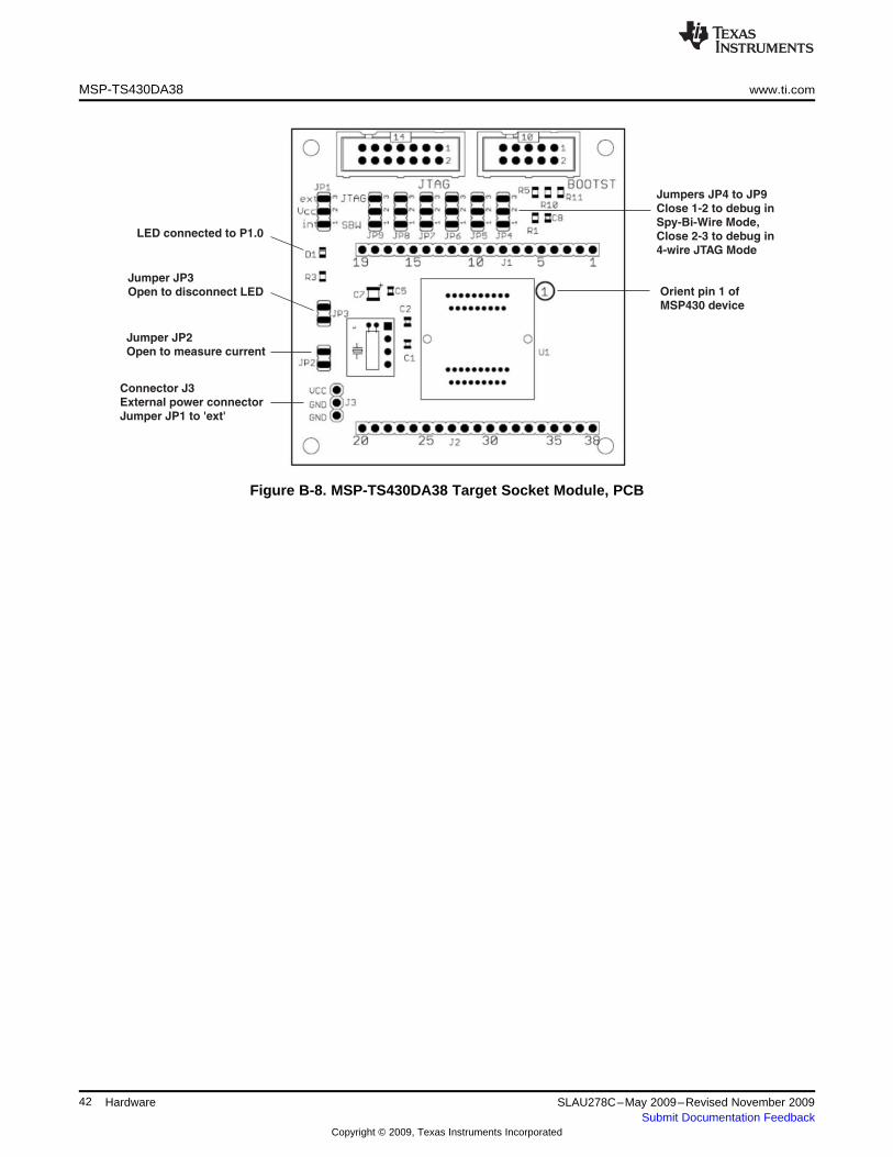
Figure B-8. MSP-TS430DA38 Target Socket Module, PCB
42 Hardware SLAU278C–May 2009–Revised November 2009Submit Documentation Feedback
Copyright © 2009, Texas Instruments Incorporated

www.ti.com MSP-TS430DA38
Table B-4. MSP-TS430DA38 Bill of Materials
No. perPos. Ref Des Description DigiKey Part No. CommentBoard
1 C1, C2 0 12pF, SMD0805 DNP
2 C7 1 10uF/10V, Tantal Size B 511-1463-2-ND
3 C5 1 100nF, SMD0805 478-3351-2-ND
4 C8 0 2.2nF, SMD0805 DNP
5 D1 1 green LED, SMD0603 475-1056-2-ND
DNP: headers andreceptacles enclosed with"SAM1029-19-6 J1, J2 0 19-pin header, TH kit.Keep vias free ofNDSAM1213-19-ND" solder.: Header:Receptacle
"J3, JP1, Place jumpers on headersJP4, JP5,7 8 3-pin header, male, TH SAM1035-03-ND JP1, JP4,JP5, JP6, JP7,JP6, JP7, JP8, JP9; Pos 1-2JP8, JP9"
8 JP2, JP3 2 2-pin header, male, TH SAM1035-02-ND Place jumper on header
Place on: JP1 - JP9; Pos9 9 Jumper 15-38-1024-ND 1-2
10 JTAG 1 14-pin connector, male, TH HRP14H-ND
DNP: Keep vias free of11 BOOTST 0 10-pin connector, male, TH solder
DNP: Keep vias free of12 Q1 0 Crystal solder
13 R1, R3 2 330 Ohm, SMD0805 541-330ATR-ND
14 R10, R11 0 0 Ohm, SMD0805 541-000ATR-ND DNP
15 R5 1 47k Ohm, SMD0805 541-47000ATR-ND
16 U1 1 Socket: IC189-0382--037 Manuf.: Yamaichi
17 PCB 1 67 x 66 mm 2 layers
Adhesive e.g., 3M Bumpons Part No. Apply to corners at bottom18 4 ~6mm width, 2mm heightPlastic feet SJ-5302 side
DNP: enclosed with kit19 MSP430 2 MSP430F2274IDA supplied by TI
43SLAU278C–May 2009–Revised November 2009 HardwareSubmit Documentation Feedback
Copyright © 2009, Texas Instruments Incorporated
MSP-TS430QFN23x0 www.ti.com
B.5 MSP-TS430QFN23x0
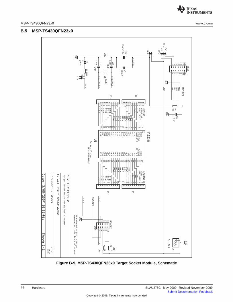
Figure B-9. MSP-TS430QFN23x0 Target Socket Module, Schematic
44 Hardware SLAU278C–May 2009–Revised November 2009Submit Documentation Feedback
Copyright © 2009, Texas Instruments Incorporated
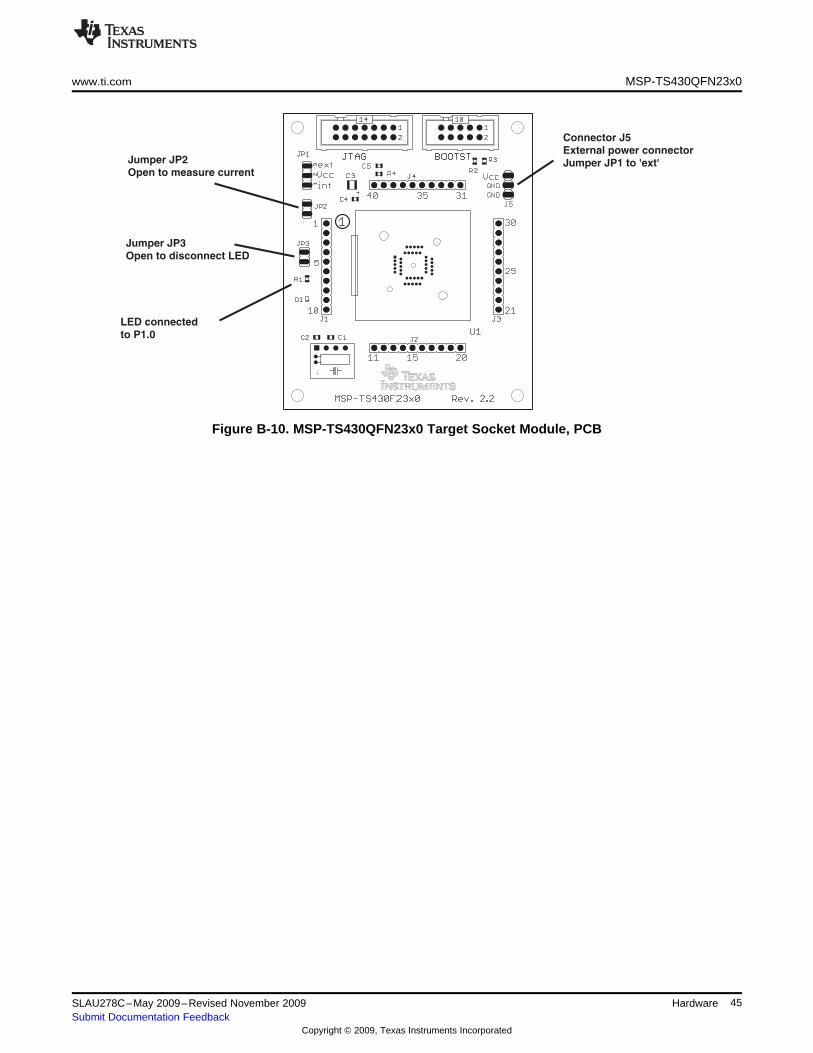
LED connected
to P1.0
Connector J5
External power connector
Jumper JP1 to 'ext'
Jumper JP3
Open to disconnect LED
Jumper JP2
Open to measure current
www.ti.com MSP-TS430QFN23x0
Figure B-10. MSP-TS430QFN23x0 Target Socket Module, PCB
45SLAU278C–May 2009–Revised November 2009 HardwareSubmit Documentation Feedback
Copyright © 2009, Texas Instruments Incorporated
MSP-TS430QFN23x0 www.ti.com
Table B-5. MSP-TS430QFN23x0 Bill of Materials
No. perPos. Ref Des Description DigiKey Part No. CommentBoard
1 C1, C2 0 12pF, SMD0805 DNP
2 C3 1 10uF/10V, Tantal Size B 511-1463-2-ND
3 C4 1 100nF, SMD0805 478-3351-2-ND
4 C5 1 10nF, SMD0805 478-1383-2-ND
5 D1 1 green LED, SMD0603 475-1056-2-ND
DNP: headers andreceptacles enclosed withJ1, J2, J3, SAM1034-10-NDSAM1212-6 0 10-pin header, TH kit.Keep vias free ofJ4 10-ND solder.: Header:Receptacle
Place jumper on header7 J5, JP1 2 3-pin header, male, TH SAM1035-03-ND JP1; Pos 1-2.
8 JP2, JP3 2 2-pin header, male, TH SAM1035-02-ND Place jumper on header
9 3 Jumper 15-38-1024-ND Place on: JP1, JP2, JP3
10 JTAG 1 14-pin connector, male, TH HRP14H-ND
DNP: Keep vias free of11 BOOTST 0 10-pin connector, male, TH solder
DNP: Keep vias free of12 Q1 0 Crystal solder
13 R1 1 330 Ohm, SMD0805 541-330ATR-ND
14 R2, R3 0 0 Ohm, SMD0805 541-000ATR-ND DNP
15 R4 1 47k Ohm, SMD0805 541-47000ATR-ND
16 U1 1 Socket: QFN-40B-0.5-01 Manuf.: Enplas
17 PCB 1 79 x 66 mm 2 layers
Adhesive e.g., 3M Bumpons Part No. Apply to corners at bottom18 4 ~6mm width, 2mm heightPlastic feet SJ-5302 side
DNP: enclosed with kit19 MSP430 2 MSP430F2370IRHA supplied by TI
46 Hardware SLAU278C–May 2009–Revised November 2009Submit Documentation Feedback
Copyright © 2009, Texas Instruments Incorporated
www.ti.com MSP-TS430DL48
B.6 MSP-TS430DL48
Figure B-11. MSP-TS430DL48 Target Socket Module, Schematic
47SLAU278C–May 2009–Revised November 2009 HardwareSubmit Documentation Feedback
Copyright © 2009, Texas Instruments Incorporated
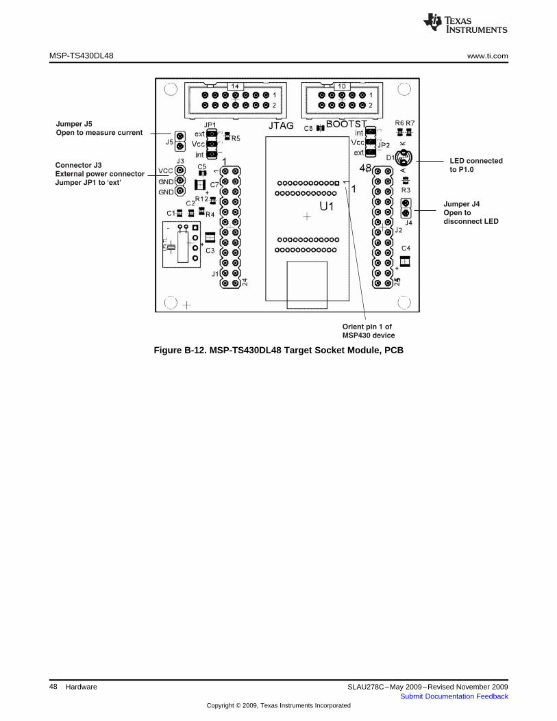
Jumper J4
Open to
disconnect LED
LED connected
to P1.0
Orient pin 1 of
MSP430 device
Jumper J5
Open to measure current
Connector J3
External power connector
Jumper JP1 to ‘ext’
MSP-TS430DL48 www.ti.com
Figure B-12. MSP-TS430DL48 Target Socket Module, PCB
48 Hardware SLAU278C–May 2009–Revised November 2009Submit Documentation Feedback
Copyright © 2009, Texas Instruments Incorporated
www.ti.com MSP-TS430DL48
Table B-6. MSP-TS430DL48 Bill of Materials
No. perPos. Ref Des Description DigiKey Part No. CommentBoard
1 C1, C2 0 12pF, SMD0805 DNP
2 C4, C7 2 10uF/10V, Tantal Size B 511-1463-2-ND
3 C3, C5 2 100nF, SMD0805 478-3351-2-ND
4 C8 1 10nF, SMD0805 478-1383-2-ND
5 D1 1 yellow LED, TH, 3mm, T1 511-1251-ND
DNP: Headers andreceptacles enclosed withSAM1034-12-NDSAM1212-6 J1, J2 0 24-pin header, TH kit.Keep vias free of12-ND solder.: Header:Receptacle
Place jumper on header7 J3, JP1, JP2 2 3-pin header, male, TH SAM1035-03-ND JP1; Pos 1-2. DNP: JP2
8 J4, J5 2 2-pin header, male, TH SAM1035-02-ND Place jumper on header
9 3 Jumper 15-38-1024-ND Place on: JP1, J4, J5
10 JTAG 1 14-pin connector, male, TH HRP14H-ND
DNP: Keep vias free of11 BOOTST 0 10-pin connector, male, TH solder
DNP: Keep vias free of12 Q1 0 Crystal solder
13 R3 1 560 Ohm, SMD0805 541-560ATR-ND
R4, R6, R7,14 2 0 Ohm, SMD0805 541-000ATR-ND DNP: R6, R7R12
15 R5 1 47k Ohm, SMD0805 541-47000ATR-ND
Socket: IC51-138716 U1 1 Manuf.: YamaichiKS-15186
17 PCB 1 58 x 66 mm 2 layers
Adhesive e.g., 3M Bumpons Part No. Apply to corners at bottom18 4 ~6mm width, 2mm heightPlastic feet SJ-5302 side
DNP: Enclosed with kit19 MSP430 2 MSP430F4270IDL supplied by TI
49SLAU278C–May 2009–Revised November 2009 HardwareSubmit Documentation Feedback
Copyright © 2009, Texas Instruments Incorporated
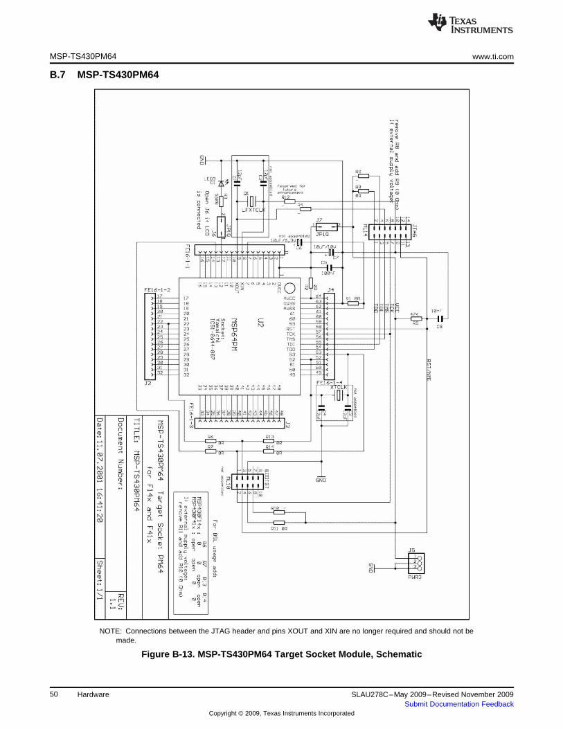
MSP-TS430PM64 www.ti.com
B.7 MSP-TS430PM64
NOTE: Connections between the JTAG header and pins XOUT and XIN are no longer required and should not bemade.
Figure B-13. MSP-TS430PM64 Target Socket Module, Schematic
50 Hardware SLAU278C–May 2009–Revised November 2009Submit Documentation Feedback
Copyright © 2009, Texas Instruments Incorporated
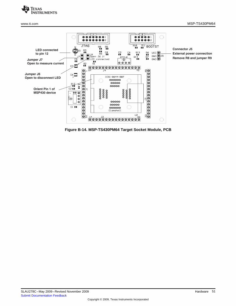
Connector J5
External power connection
Remove R8 and jumper R9
LED connected
to pin 12
Jumper J6
Open to disconnect LED
Jumper J7
Open to measure current
Orient Pin 1 of
MSP430 device
www.ti.com MSP-TS430PM64
Figure B-14. MSP-TS430PM64 Target Socket Module, PCB
51SLAU278C–May 2009–Revised November 2009 HardwareSubmit Documentation Feedback
Copyright © 2009, Texas Instruments Incorporated
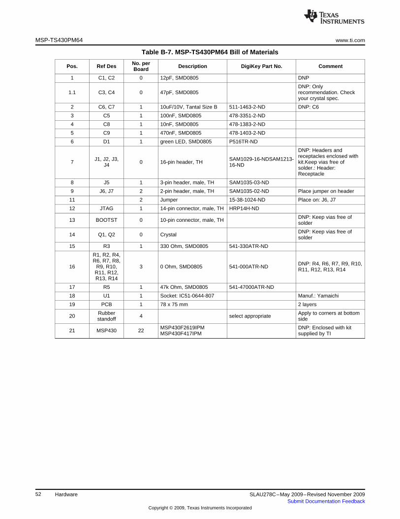
MSP-TS430PM64 www.ti.com
Table B-7. MSP-TS430PM64 Bill of Materials
No. perPos. Ref Des Description DigiKey Part No. CommentBoard
1 C1, C2 0 12pF, SMD0805 DNP
DNP: Only1.1 C3, C4 0 47pF, SMD0805 recommendation. Check
your crystal spec.
2 C6, C7 1 10uF/10V, Tantal Size B 511-1463-2-ND DNP: C6
3 C5 1 100nF, SMD0805 478-3351-2-ND
4 C8 1 10nF, SMD0805 478-1383-2-ND
5 C9 1 470nF, SMD0805 478-1403-2-ND
6 D1 1 green LED, SMD0805 P516TR-ND
DNP: Headers andreceptacles enclosed withJ1, J2, J3, SAM1029-16-NDSAM1213-7 0 16-pin header, TH kit.Keep vias free ofJ4 16-ND solder.: Header:Receptacle
8 J5 1 3-pin header, male, TH SAM1035-03-ND
9 J6, J7 2 2-pin header, male, TH SAM1035-02-ND Place jumper on header
11 2 Jumper 15-38-1024-ND Place on: J6, J7
12 JTAG 1 14-pin connector, male, TH HRP14H-ND
DNP: Keep vias free of13 BOOTST 0 10-pin connector, male, TH solder
DNP: Keep vias free of14 Q1, Q2 0 Crystal solder
15 R3 1 330 Ohm, SMD0805 541-330ATR-ND
R1, R2, R4,R6, R7, R8, DNP: R4, R6, R7, R9, R10,16 R9, R10, 3 0 Ohm, SMD0805 541-000ATR-ND R11, R12, R13, R14R11, R12,R13, R14
17 R5 1 47k Ohm, SMD0805 541-47000ATR-ND
18 U1 1 Socket: IC51-0644-807 Manuf.: Yamaichi
19 PCB 1 78 x 75 mm 2 layers
Rubber Apply to corners at bottom20 4 select appropriatestandoff side
MSP430F2619IPM DNP: Enclosed with kit21 MSP430 22 MSP430F417IPM supplied by TI
52 Hardware SLAU278C–May 2009–Revised November 2009Submit Documentation Feedback
Copyright © 2009, Texas Instruments Incorporated
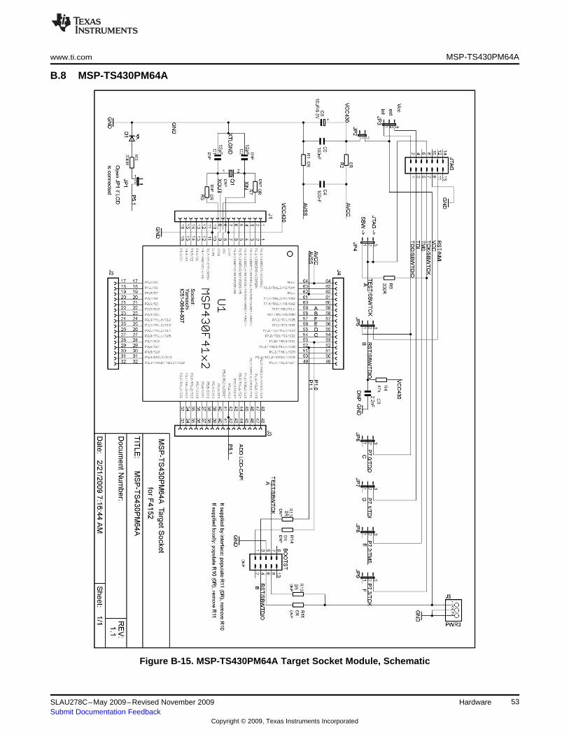
www.ti.com MSP-TS430PM64A
B.8 MSP-TS430PM64A
Figure B-15. MSP-TS430PM64A Target Socket Module, Schematic
53SLAU278C–May 2009–Revised November 2009 HardwareSubmit Documentation Feedback
Copyright © 2009, Texas Instruments Incorporated
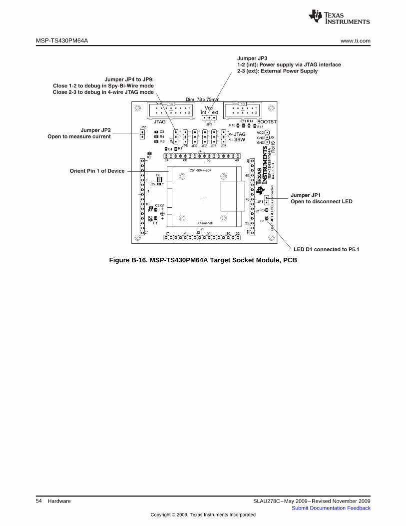
Jumper JP2
Open to measure current
Jumper JP1
Open to disconnect LED
LED D1 connected to P5.1
Jumper JP3
1-2 (int): Power supply via JTAG interface
2-3 (ext): External Power Supply
Jumper JP4 to JP9:
Close 1-2 to debug in Spy-Bi-Wire mode
Close 2-3 to debug in 4-wire JTAG mode
Orient Pin 1 of Device
MSP-TS430PM64A www.ti.com
Figure B-16. MSP-TS430PM64A Target Socket Module, PCB
54 Hardware SLAU278C–May 2009–Revised November 2009Submit Documentation Feedback
Copyright © 2009, Texas Instruments Incorporated
www.ti.com MSP-TS430PM64A
Table B-8. MSP-TS430PM64A Bill of Materials
No. perPos. Ref Des Description DigiKey Part No. CommentBoard
1 C1, C2, 0 12pF, SMD0805 DNP
2 C3 0 2.2nF, SMD0805 DNP
3 C6, 1 10uF/10V, Tantal Size B 511-1463-2-ND
4 C4, C5 2 100nF, SMD0805 478-3351-2-ND
5 D1 1 green LED, SMD0805 P516TR-ND
DNP: Headers andreceptacles enclosed withJ1, J2, J3, SAM1029-16-NDSAM1213-6 0 16-pin header, TH kit. Keep vias free ofJ4 16-ND solder.: Header:Receptacle
J5, JP3,JP4, JP5,7 8 3-pin header, male, TH SAM1035-03-NDJP6, JP7,JP8, JP9
8 JP1, JP2 2 2-pin header, male, TH SAM1035-02-ND Place jumper on header
9 2 Jumper 15-38-1024-ND Place on: J6, J7
10 JTAG 1 14-pin connector, male, TH HRP14H-ND
DNP: Keep vias free of11 BOOTST 0 10-pin connector, male, TH solder
DNP: Keep vias free of12 Q1, Q2 0 Crystal solder
13 R3, R6 2 330 Ohm, SMD0805 541-330ATR-ND
R1, R2, R5,R7, R9, R10, DNP: R5, R7, R9, R10,14 2 0 Ohm, SMD0805 541-000ATR-NDR11, R13, R11, R13, R14
R14
15 R4 1 47k Ohm, SMD0805 541-47000ATR-ND
16 U1 1 Socket: IC51-0644-807 Manuf.: Yamaichi
17 PCB 1 78 x 75 mm 4 layers
Rubber Apply to corners at bottom18 4 select appropriatestand off side
DNP: Enclosed with kit19 MSP430 2 MSP430F4152IPM supplied by TI
55SLAU278C–May 2009–Revised November 2009 HardwareSubmit Documentation Feedback
Copyright © 2009, Texas Instruments Incorporated
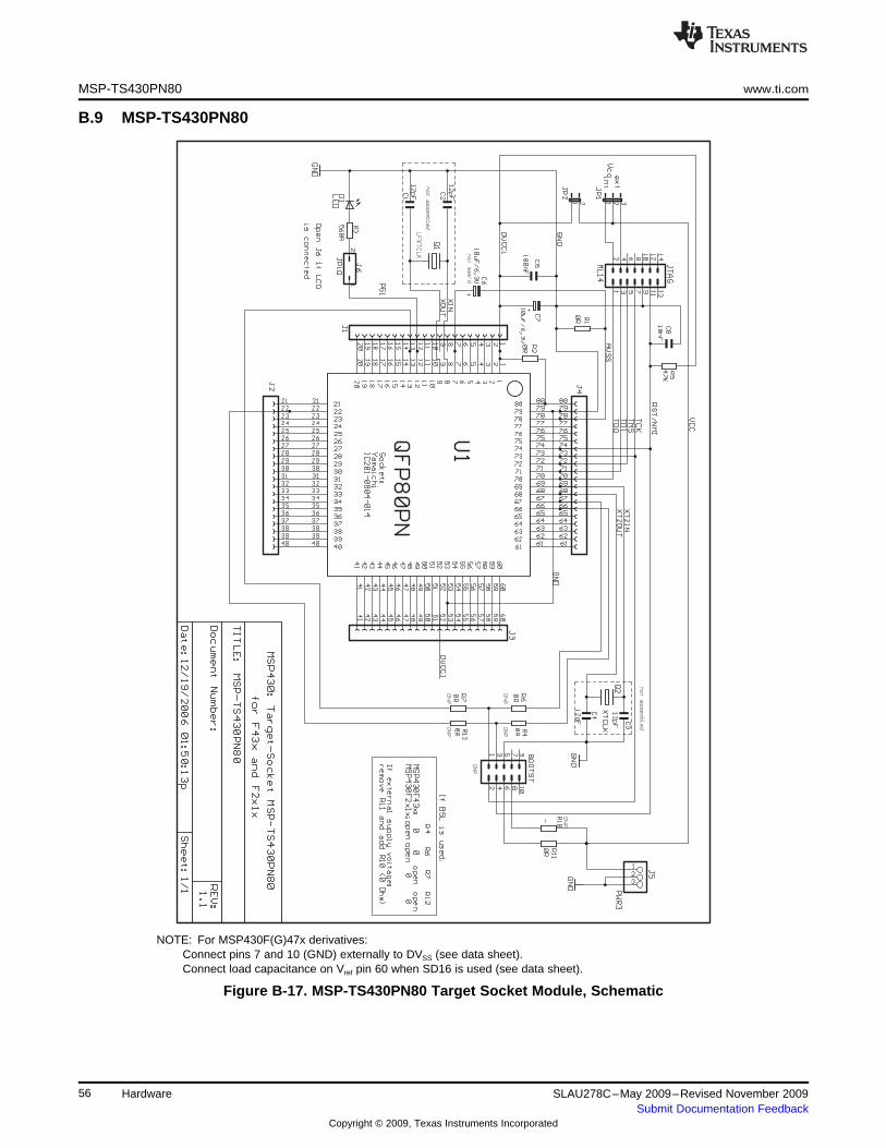
MSP-TS430PN80 www.ti.com
B.9 MSP-TS430PN80
NOTE: For MSP430F(G)47x derivatives:Connect pins 7 and 10 (GND) externally to DVSS (see data sheet).Connect load capacitance on Vref pin 60 when SD16 is used (see data sheet).
Figure B-17. MSP-TS430PN80 Target Socket Module, Schematic
56 Hardware SLAU278C–May 2009–Revised November 2009Submit Documentation Feedback
Copyright © 2009, Texas Instruments Incorporated
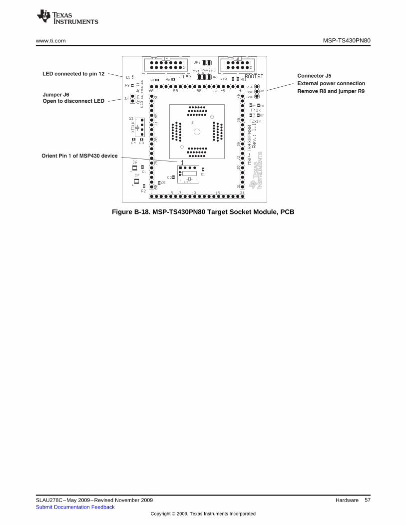
Connector J5
External power connection
Remove R8 and jumper R9
LED connected to pin 12
Jumper J6
Open to disconnect LED
Orient Pin 1 of MSP430 device
www.ti.com MSP-TS430PN80
Figure B-18. MSP-TS430PN80 Target Socket Module, PCB
57SLAU278C–May 2009–Revised November 2009 HardwareSubmit Documentation Feedback
Copyright © 2009, Texas Instruments Incorporated
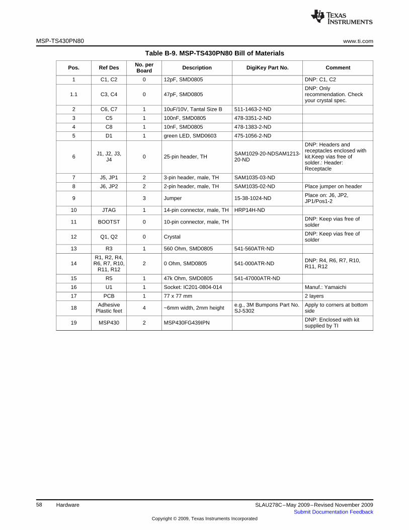
MSP-TS430PN80 www.ti.com
Table B-9. MSP-TS430PN80 Bill of Materials
No. perPos. Ref Des Description DigiKey Part No. CommentBoard
1 C1, C2 0 12pF, SMD0805 DNP: C1, C2
DNP: Only1.1 C3, C4 0 47pF, SMD0805 recommendation. Check
your crystal spec.
2 C6, C7 1 10uF/10V, Tantal Size B 511-1463-2-ND
3 C5 1 100nF, SMD0805 478-3351-2-ND
4 C8 1 10nF, SMD0805 478-1383-2-ND
5 D1 1 green LED, SMD0603 475-1056-2-ND
DNP: Headers andreceptacles enclosed withJ1, J2, J3, SAM1029-20-NDSAM1213-6 0 25-pin header, TH kit.Keep vias free ofJ4 20-ND solder.: Header:Receptacle
7 J5, JP1 2 3-pin header, male, TH SAM1035-03-ND
8 J6, JP2 2 2-pin header, male, TH SAM1035-02-ND Place jumper on header
Place on: J6, JP2,9 3 Jumper 15-38-1024-ND JP1/Pos1-2
10 JTAG 1 14-pin connector, male, TH HRP14H-ND
DNP: Keep vias free of11 BOOTST 0 10-pin connector, male, TH solder
DNP: Keep vias free of12 Q1, Q2 0 Crystal solder
13 R3 1 560 Ohm, SMD0805 541-560ATR-ND
R1, R2, R4, DNP: R4, R6, R7, R10,14 R6, R7, R10, 2 0 Ohm, SMD0805 541-000ATR-ND R11, R12R11, R12
15 R5 1 47k Ohm, SMD0805 541-47000ATR-ND
16 U1 1 Socket: IC201-0804-014 Manuf.: Yamaichi
17 PCB 1 77 x 77 mm 2 layers
Adhesive e.g., 3M Bumpons Part No. Apply to corners at bottom18 4 ~6mm width, 2mm heightPlastic feet SJ-5302 side
DNP: Enclosed with kit19 MSP430 2 MSP430FG439IPN supplied by TI
58 Hardware SLAU278C–May 2009–Revised November 2009Submit Documentation Feedback
Copyright © 2009, Texas Instruments Incorporated
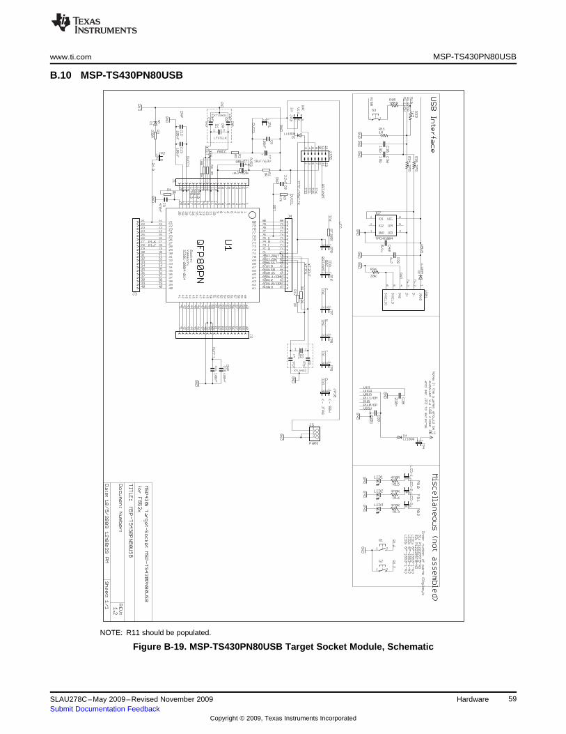
www.ti.com MSP-TS430PN80USB
B.10 MSP-TS430PN80USB
NOTE: R11 should be populated.
Figure B-19. MSP-TS430PN80USB Target Socket Module, Schematic
59SLAU278C–May 2009–Revised November 2009 HardwareSubmit Documentation Feedback
Copyright © 2009, Texas Instruments Incorporated
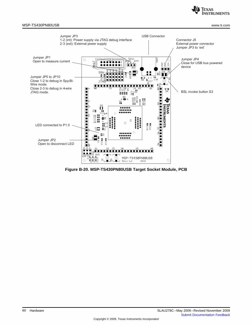
Jumper JP31-2 (int): Power supply via JTAG debug interface2-3 (ext): External power supply
Connector J5External power connectorJumper JP3 to ‘ext’
USB Connector
BSL invoke button S3
Jumper JP4Close for USB bus powereddevice
Jumper JP2Open to disconnect LED
LED connected to P1.0
Jumper JP1Open to measure current
Jumper JP5 to JP10
Close 1-2 to debug in Spy-Bi-Wire mode.
Close 2-3 to debug in 4-wireJTAG mode.
MSP-TS430PN80USB www.ti.com
Figure B-20. MSP-TS430PN80USB Target Socket Module, PCB
60 Hardware SLAU278C–May 2009–Revised November 2009Submit Documentation Feedback
Copyright © 2009, Texas Instruments Incorporated
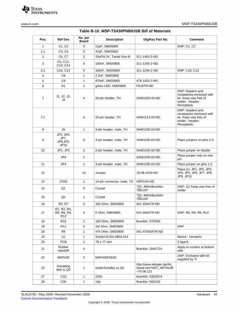
www.ti.com MSP-TS430PN80USB
Table B-10. MSP-TS430PN80USB Bill of Materials
No. perPos. Ref Des Description DigiKey Part No. CommentBoard
1 C1, C2 0 12pF, SMD0805 DNP: C1, C2
1.1 C3, C4 2 47pF, SMD0805
2 C6, C7 2 10uF/6.3V, Tantal Size B 511-1463-2-ND
C5, C11,3 4 100nF, SMD0805 311-1245-2-NDC13, C14
3.1 C10, C12 0 100nF, SMD0805 311-1245-2-ND DNP: C10, C12
4 C8 1 2.2nF, SMD0805
5 C9 1 470nF, SMD0805 478-1403-2-ND
6 D1 1 green LED, SMD0805 P516TR-ND
DNP: headers andreceptacles enclosed withJ1, J2, J3,7 4 20-pin header, TH SAM1029-20-ND kit. Keep vias free ofJ4 solder.: Header:Receptacle
DNP: headers andreceptacles enclosed with
7.1 4 20-pin header, TH SAM1213-20-ND kit. Keep vias free ofsolder.: Header:Receptacle
8 J5 1 3-pin header, male, TH SAM1035-03-ND
JP5, JP6,JP7,9 6 3-pin header, male, TH SAM1035-03-ND Place jumpers on pins 2-3JP8,JP9,JP10
10 JP1, JP2 2 2-pin header, male, TH SAM1035-02-ND Place jumper on header
Place jumper only on oneJP4 1 SAM1035-02-ND pin
11 JP3 1 3-pin header, male, TH SAM1035-03-ND Place jumper on pins 1-2
Place on: JP1, JP2, JP3,12 10 Jumper 15-38-1024-ND JP4, JP5, JP6, JP7, JP8,
JP9, JP10
13 JTAG 1 14-pin connector, male, TH HRP14H-ND
"Q2: 4MHzBuerklin: DNP: Q1 Keep vias free of14 Q1 0 Crystal 78D134" solder
"Q2: 4MHzBuerklin:15 Q2 1 Crystal 78D134"
16 R3, R7 2 330 Ohm, SMD0805 541-330ATR-ND
R1, R2, R4,17 R6, R8, R9, 3 0 Ohm, SMD0805 541-000ATR-ND DNP: R6, R8, R9, R12
R12
18 R10 1 100 Ohm, SMD0805 Buerklin: 07E500
18 R11 0 1M Ohm, SMD0805 DNP
18 R5 1 47k Ohm, SMD0805 541-47000ATR-ND
19 U1 1 Socket:IC201-0804-014 Manuf.: Yamaichi
20 PCB 1 79 x 77 mm 2 layers
Rubber Apply to corners at bottom21 4 Buerklin: 20H1724standoff side
DNP: Enclosed with kit22 MSP430 2 MSP430F5529 supplied by TI
http://www.ettinger.de/Art_Insulating23 1 IsolierScheibe zu Q2 Detail.cfm?ART_ARTNUMdisk to Q2 =70.08.121
27 C33 1 220n Buerklin: 53D2074
28 C35 1 10p Buerklin: 56D102
61SLAU278C–May 2009–Revised November 2009 HardwareSubmit Documentation Feedback
Copyright © 2009, Texas Instruments Incorporated
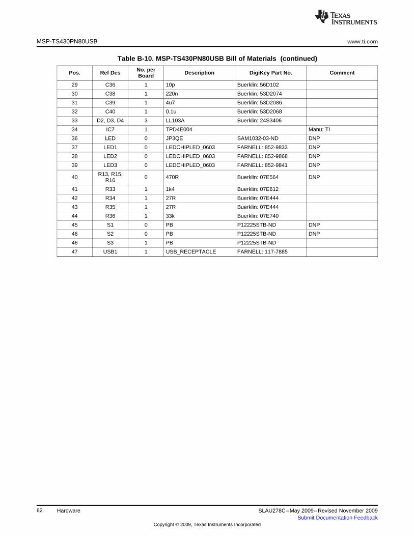
MSP-TS430PN80USB www.ti.com
Table B-10. MSP-TS430PN80USB Bill of Materials (continued)
No. perPos. Ref Des Description DigiKey Part No. CommentBoard
29 C36 1 10p Buerklin: 56D102
30 C38 1 220n Buerklin: 53D2074
31 C39 1 4u7 Buerklin: 53D2086
32 C40 1 0.1u Buerklin: 53D2068
33 D2, D3, D4 3 LL103A Buerklin: 24S3406
34 IC7 1 TPD4E004 Manu: TI
36 LED 0 JP3QE SAM1032-03-ND DNP
37 LED1 0 LEDCHIPLED_0603 FARNELL: 852-9833 DNP
38 LED2 0 LEDCHIPLED_0603 FARNELL: 852-9868 DNP
39 LED3 0 LEDCHIPLED_0603 FARNELL: 852-9841 DNP
R13, R15,40 0 470R Buerklin: 07E564 DNPR16
41 R33 1 1k4 Buerklin: 07E612
42 R34 1 27R Buerklin: 07E444
43 R35 1 27R Buerklin: 07E444
44 R36 1 33k Buerklin: 07E740
45 S1 0 PB P12225STB-ND DNP
46 S2 0 PB P12225STB-ND DNP
46 S3 1 PB P12225STB-ND
47 USB1 1 USB_RECEPTACLE FARNELL: 117-7885
62 Hardware SLAU278C–May 2009–Revised November 2009Submit Documentation Feedback
Copyright © 2009, Texas Instruments Incorporated
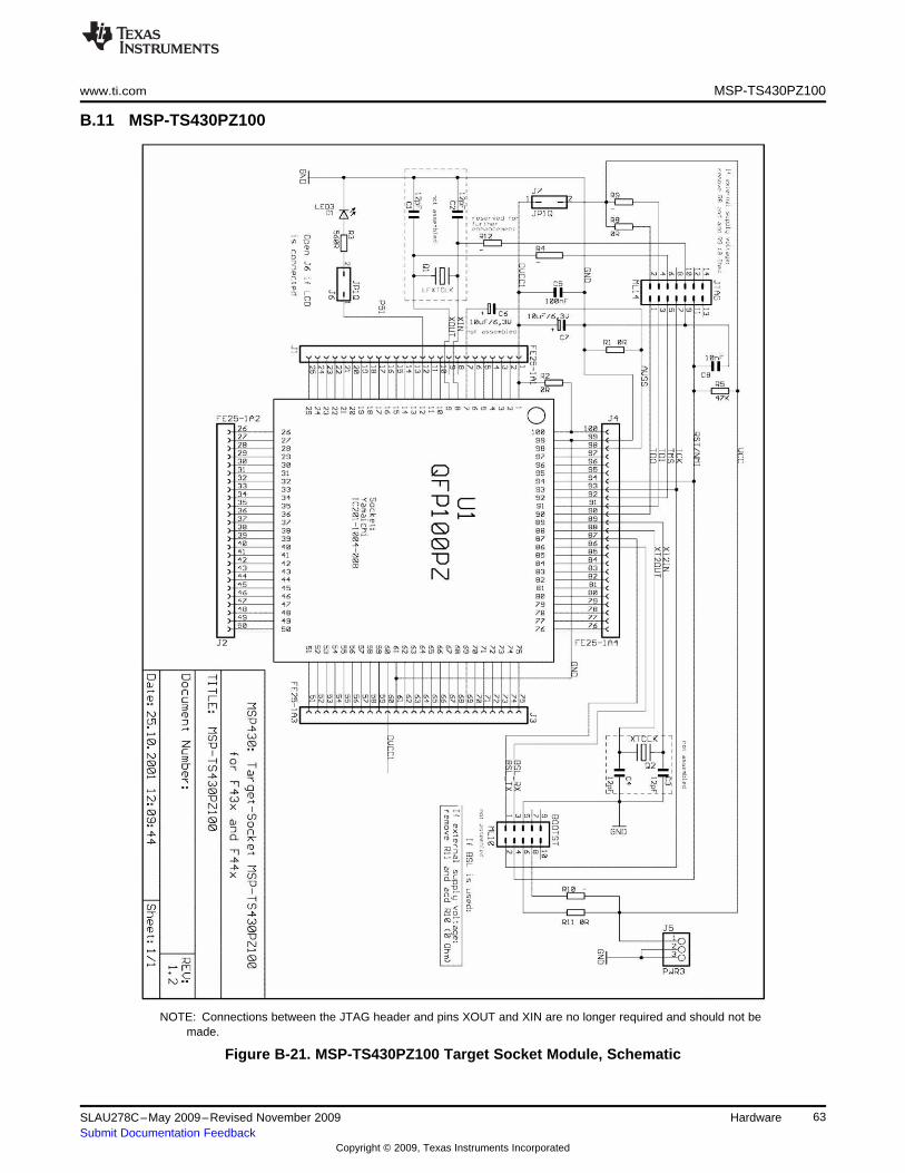
www.ti.com MSP-TS430PZ100
B.11 MSP-TS430PZ100
NOTE: Connections between the JTAG header and pins XOUT and XIN are no longer required and should not bemade.
Figure B-21. MSP-TS430PZ100 Target Socket Module, Schematic
63SLAU278C–May 2009–Revised November 2009 HardwareSubmit Documentation Feedback
Copyright © 2009, Texas Instruments Incorporated
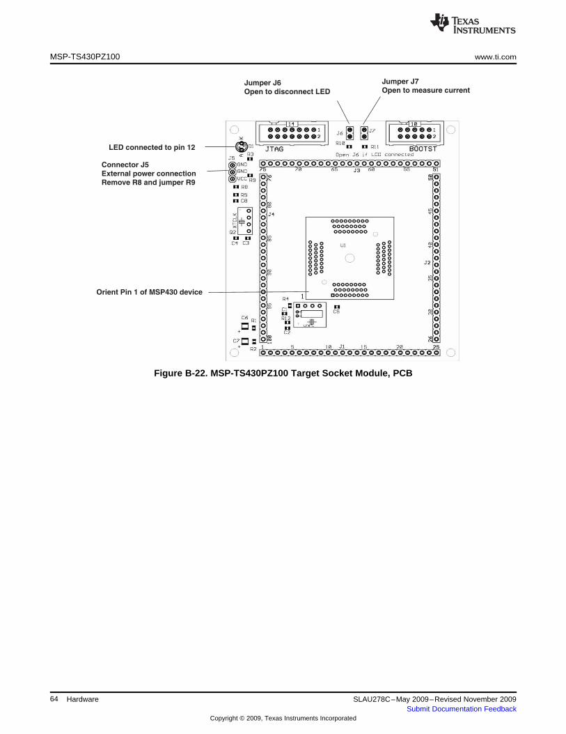
Connector J5
External power connection
Remove R8 and jumper R9
LED connected to pin 12
Jumper J6
Open to disconnect LED
Orient Pin 1 of MSP430 device
Jumper J7
Open to measure current
MSP-TS430PZ100 www.ti.com
Figure B-22. MSP-TS430PZ100 Target Socket Module, PCB
64 Hardware SLAU278C–May 2009–Revised November 2009Submit Documentation Feedback
Copyright © 2009, Texas Instruments Incorporated
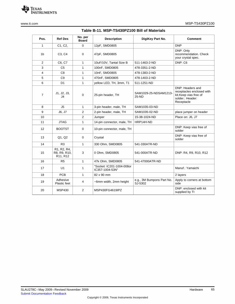
www.ti.com MSP-TS430PZ100
Table B-11. MSP-TS430PZ100 Bill of Materials
No. perPos. Ref Des Description DigiKey Part No. CommentBoard
1 C1, C2, 0 12pF, SMD0805 DNP
DNP: Only1b C3, C4 0 47pF, SMD0805 recommendation. Check
your crystal spec.
2 C6, C7 1 10uF/10V, Tantal Size B 511-1463-2-ND DNP: C6
3 C5 1 100nF, SMD0805 478-3351-2-ND
4 C8 1 10nF, SMD0805 478-1383-2-ND
5 C9 1 470nF, SMD0805 478-1403-2-ND
6 D1 1 yellow LED, TH, 3mm, T1 511-1251-ND
DNP: Headers andreceptacles enclosed withJ1, J2, J3, SAM1029-25-NDSAM1213-7 0 25-pin header, TH kit.Keep vias free ofJ4 25-ND solder.: Header:Receptacle
8 J5 1 3-pin header, male, TH SAM1035-03-ND
9 J6, J7 2 2-pin header, male, TH SAM1035-02-ND place jumper on header
10 2 Jumper 15-38-1024-ND Place on: J6, J7
11 JTAG 1 14-pin connector, male, TH HRP14H-ND
DNP: Keep vias free of12 BOOTST 0 10-pin connector, male, TH solder
DNP: Keep vias free of13 Q1, Q2 0 Crystal solder
14 R3 1 330 Ohm, SMD0805 541-330ATR-ND
R1, R2, R4,15 R8, R9, R10, 3 0 Ohm, SMD0805 541-000ATR-ND DNP: R4, R9, R10, R12
R11, R12
16 R5 1 47k Ohm, SMD0805 541-47000ATR-ND
"Socket: IC201-1004-008or17 U1 1 Manuf.: YamaichiIC357-1004-53N"
18 PCB 1 82 x 90 mm 2 layers
Adhesive e.g., 3M Bumpons Part No. Apply to corners at bottom19 4 ~6mm width, 2mm heightPlastic feet SJ-5302 side
DNP: enclosed with kit20 MSP430 2 MSP430FG4619IPZ supplied by TI
65SLAU278C–May 2009–Revised November 2009 HardwareSubmit Documentation Feedback
Copyright © 2009, Texas Instruments Incorporated
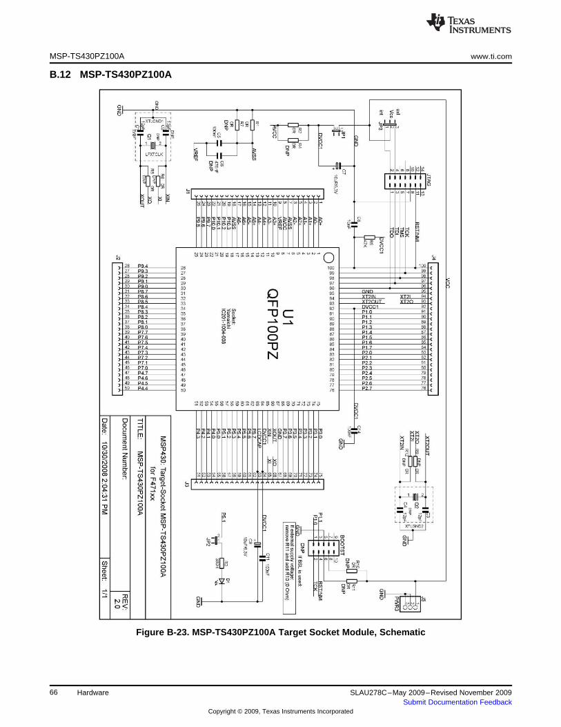
MSP-TS430PZ100A www.ti.com
B.12 MSP-TS430PZ100A
Figure B-23. MSP-TS430PZ100A Target Socket Module, Schematic
66 Hardware SLAU278C–May 2009–Revised November 2009Submit Documentation Feedback
Copyright © 2009, Texas Instruments Incorporated
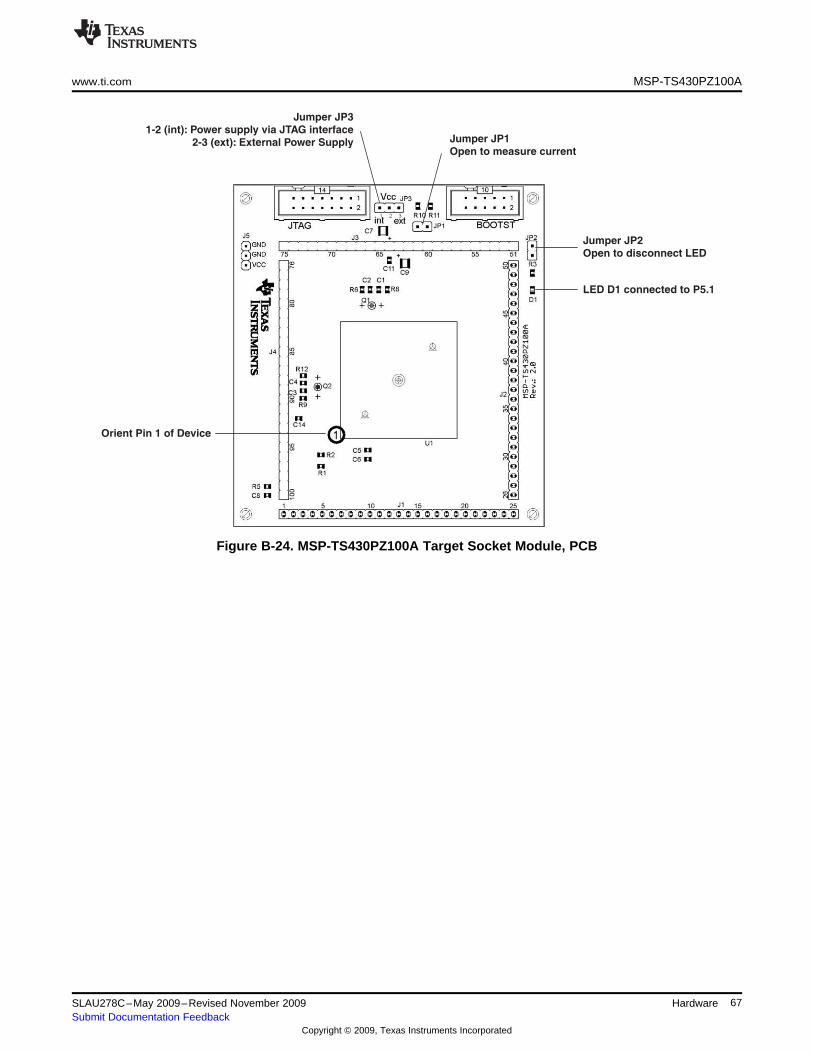
Jumper JP1
Open to measure current
Jumper JP2
Open to disconnect LED
LED D1 connected to P5.1
Jumper JP3
1-2 (int): Power supply via JTAG interface
2-3 (ext): External Power Supply
Orient Pin 1 of Device
www.ti.com MSP-TS430PZ100A
Figure B-24. MSP-TS430PZ100A Target Socket Module, PCB
67SLAU278C–May 2009–Revised November 2009 HardwareSubmit Documentation Feedback
Copyright © 2009, Texas Instruments Incorporated
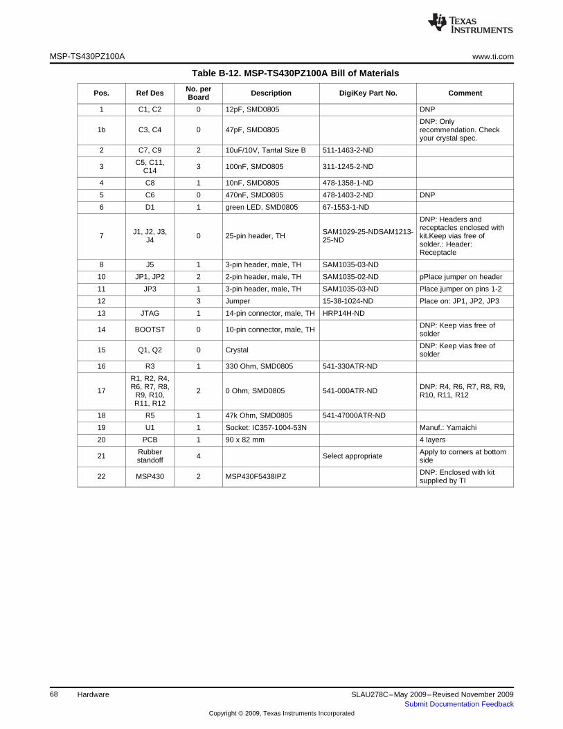
MSP-TS430PZ100A www.ti.com
Table B-12. MSP-TS430PZ100A Bill of Materials
No. perPos. Ref Des Description DigiKey Part No. CommentBoard
1 C1, C2 0 12pF, SMD0805 DNP
DNP: Only1b C3, C4 0 47pF, SMD0805 recommendation. Check
your crystal spec.
2 C7, C9 2 10uF/10V, Tantal Size B 511-1463-2-ND
C5, C11,3 3 100nF, SMD0805 311-1245-2-NDC14
4 C8 1 10nF, SMD0805 478-1358-1-ND
5 C6 0 470nF, SMD0805 478-1403-2-ND DNP
6 D1 1 green LED, SMD0805 67-1553-1-ND
DNP: Headers andreceptacles enclosed withJ1, J2, J3, SAM1029-25-NDSAM1213-7 0 25-pin header, TH kit.Keep vias free ofJ4 25-ND solder.: Header:Receptacle
8 J5 1 3-pin header, male, TH SAM1035-03-ND
10 JP1, JP2 2 2-pin header, male, TH SAM1035-02-ND pPlace jumper on header
11 JP3 1 3-pin header, male, TH SAM1035-03-ND Place jumper on pins 1-2
12 3 Jumper 15-38-1024-ND Place on: JP1, JP2, JP3
13 JTAG 1 14-pin connector, male, TH HRP14H-ND
DNP: Keep vias free of14 BOOTST 0 10-pin connector, male, TH solder
DNP: Keep vias free of15 Q1, Q2 0 Crystal solder
16 R3 1 330 Ohm, SMD0805 541-330ATR-ND
R1, R2, R4,R6, R7, R8, DNP: R4, R6, R7, R8, R9,17 2 0 Ohm, SMD0805 541-000ATR-NDR9, R10, R10, R11, R12R11, R12
18 R5 1 47k Ohm, SMD0805 541-47000ATR-ND
19 U1 1 Socket: IC357-1004-53N Manuf.: Yamaichi
20 PCB 1 90 x 82 mm 4 layers
Rubber Apply to corners at bottom21 4 Select appropriatestandoff side
DNP: Enclosed with kit22 MSP430 2 MSP430F5438IPZ supplied by TI
68 Hardware SLAU278C–May 2009–Revised November 2009Submit Documentation Feedback
Copyright © 2009, Texas Instruments Incorporated
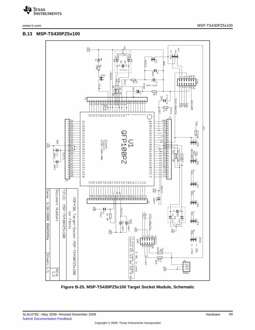
www.ti.com MSP-TS430PZ5x100
B.13 MSP-TS430PZ5x100
Figure B-25. MSP-TS430PZ5x100 Target Socket Module, Schematic
69SLAU278C–May 2009–Revised November 2009 HardwareSubmit Documentation Feedback
Copyright © 2009, Texas Instruments Incorporated
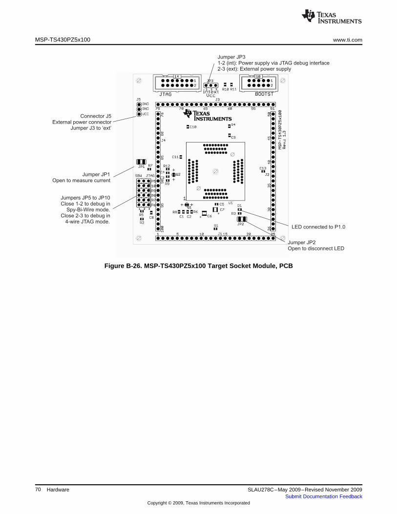
Connector J5External power connector
Jumper J3 to ‘ext’
Jumper JP1Open to measure current
Jumpers JP5 to JP10Close 1-2 to debug in
Spy-Bi-Wire mode.Close 2-3 to debug in
4-wire JTAG mode.
Jumper JP2Open to disconnect LED
LED connected to P1.0
Jumper JP31-2 (int): Power supply via JTAG debug interface2-3 (ext): External power supply
MSP-TS430PZ5x100 www.ti.com
Figure B-26. MSP-TS430PZ5x100 Target Socket Module, PCB
70 Hardware SLAU278C–May 2009–Revised November 2009Submit Documentation Feedback
Copyright © 2009, Texas Instruments Incorporated
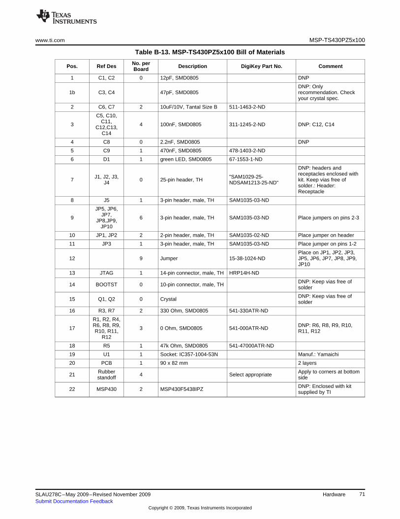
www.ti.com MSP-TS430PZ5x100
Table B-13. MSP-TS430PZ5x100 Bill of Materials
No. perPos. Ref Des Description DigiKey Part No. CommentBoard
1 C1, C2 0 12pF, SMD0805 DNP
DNP: Only1b C3, C4 47pF, SMD0805 recommendation. Check
your crystal spec.
2 C6, C7 2 10uF/10V, Tantal Size B 511-1463-2-ND
C5, C10,C11,3 4 100nF, SMD0805 311-1245-2-ND DNP: C12, C14C12,C13,C14
4 C8 0 2.2nF, SMD0805 DNP
5 C9 1 470nF, SMD0805 478-1403-2-ND
6 D1 1 green LED, SMD0805 67-1553-1-ND
DNP: headers andreceptacles enclosed withJ1, J2, J3, "SAM1029-25-7 0 25-pin header, TH kit. Keep vias free ofJ4 NDSAM1213-25-ND" solder.: Header:Receptacle
8 J5 1 3-pin header, male, TH SAM1035-03-ND
JP5, JP6,JP7,9 6 3-pin header, male, TH SAM1035-03-ND Place jumpers on pins 2-3JP8,JP9,JP10
10 JP1, JP2 2 2-pin header, male, TH SAM1035-02-ND Place jumper on header
11 JP3 1 3-pin header, male, TH SAM1035-03-ND Place jumper on pins 1-2
Place on JP1, JP2, JP3,12 9 Jumper 15-38-1024-ND JP5, JP6, JP7, JP8, JP9,
JP10
13 JTAG 1 14-pin connector, male, TH HRP14H-ND
DNP: Keep vias free of14 BOOTST 0 10-pin connector, male, TH solder
DNP: Keep vias free of15 Q1, Q2 0 Crystal solder
16 R3, R7 2 330 Ohm, SMD0805 541-330ATR-ND
R1, R2, R4,R6, R8, R9, DNP: R6, R8, R9, R10,17 3 0 Ohm, SMD0805 541-000ATR-NDR10, R11, R11, R12
R12
18 R5 1 47k Ohm, SMD0805 541-47000ATR-ND
19 U1 1 Socket: IC357-1004-53N Manuf.: Yamaichi
20 PCB 1 90 x 82 mm 2 layers
Rubber Apply to corners at bottom21 4 Select appropriatestandoff side
DNP: Enclosed with kit22 MSP430 2 MSP430F5438IPZ supplied by TI
71SLAU278C–May 2009–Revised November 2009 HardwareSubmit Documentation Feedback
Copyright © 2009, Texas Instruments Incorporated
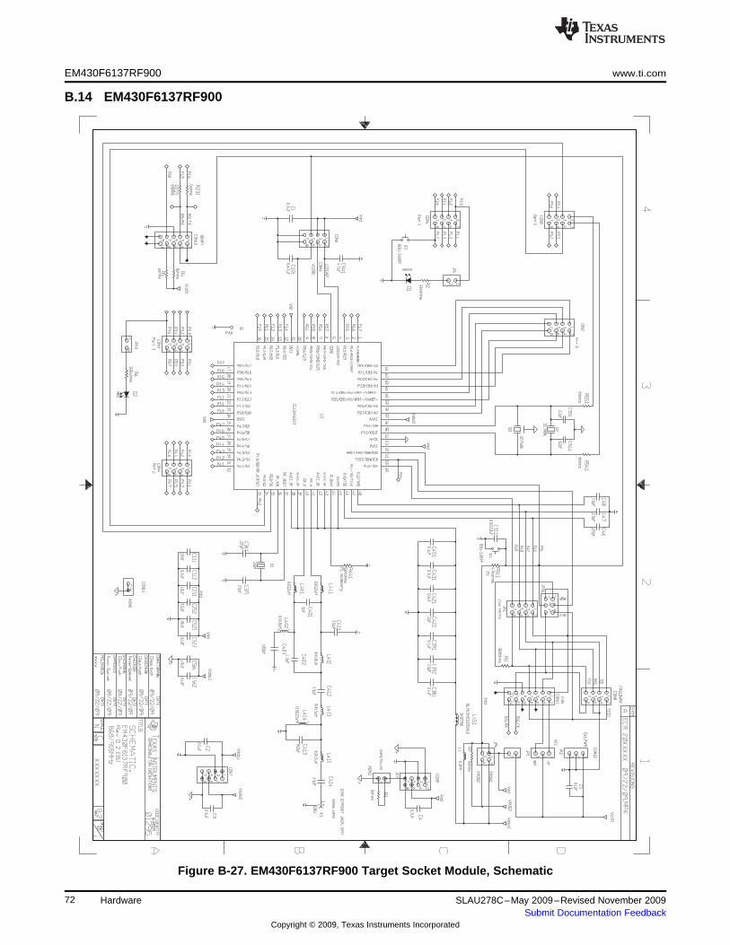
EM430F6137RF900 www.ti.com
B.14 EM430F6137RF900
Figure B-27. EM430F6137RF900 Target Socket Module, Schematic
72 Hardware SLAU278C–May 2009–Revised November 2009Submit Documentation Feedback
Copyright © 2009, Texas Instruments Incorporated
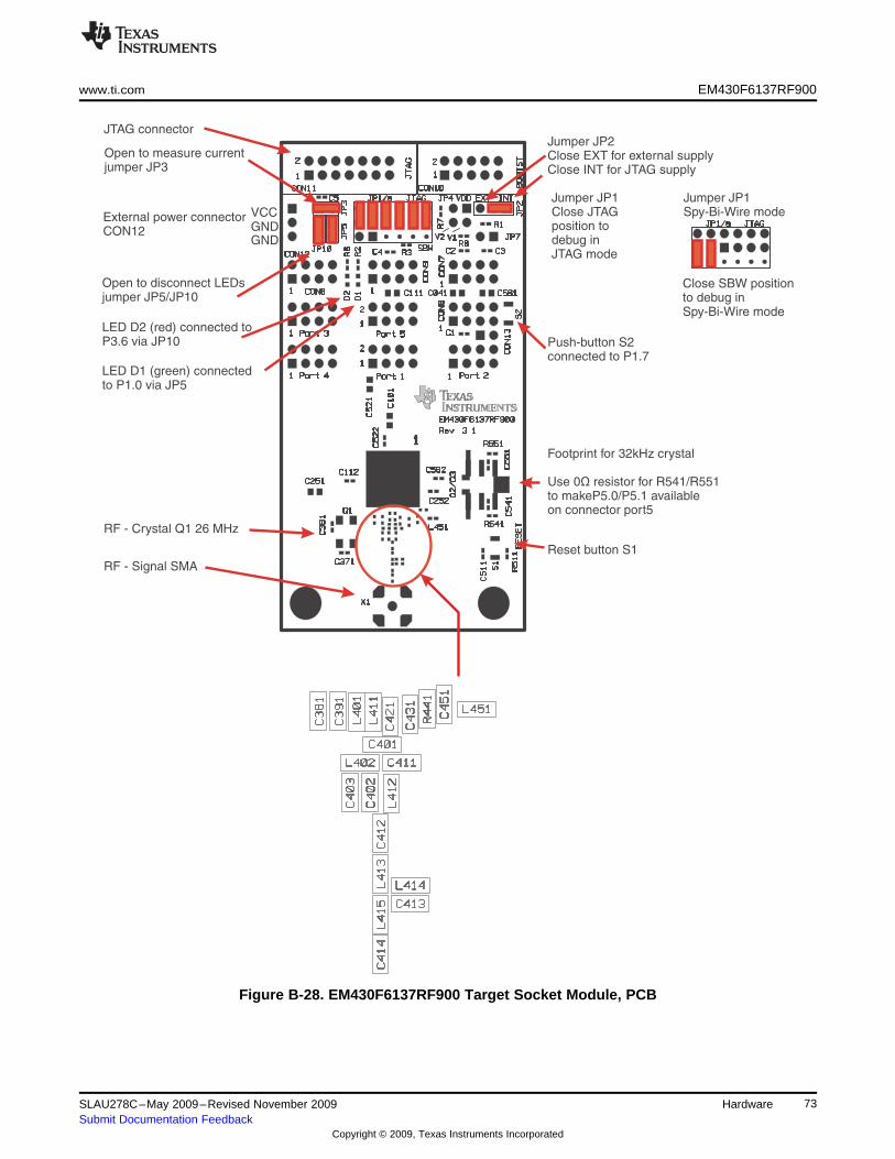
JTAG connector
External power connectorCON12
GNDGNDVCC
Open to disconnect LEDsjumper JP5/JP10
LED D2 (red) connected toP3.6 via JP10
LED D1 (green) connectedto P1.0 via JP5
RF - Crystal Q1 26 MHz
RF - Signal SMA
Reset button S1
Push-button S2connected to P1.7
Jumper JP1Close JTAGposition todebug inJTAG mode
Jumper JP2Close EXT for external supplyClose INT for JTAG supply
Close SBW positionto debug inSpy-Bi-Wire mode
Jumper JP1Spy-Bi-Wire mode
Footprint for 32kHz crystal
Use 0 resistor for R541/R551to makeP5.0/P5.1 availableon connector port5
Ω
Open to measure currentjumper JP3
www.ti.com EM430F6137RF900
Figure B-28. EM430F6137RF900 Target Socket Module, PCB
73SLAU278C–May 2009–Revised November 2009 HardwareSubmit Documentation Feedback
Copyright © 2009, Texas Instruments Incorporated
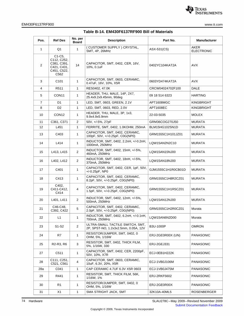
EM430F6137RF900 www.ti.com
Table B-14. EM430F6137RF900 Bill of Materials
No. perPos. Ref Des Description Part No. ManufacturerBoard
( CUSTOMER SUPPLY ) CRYSTAL, AKER1 Q1 1 ASX-531(CS)SMT, 4P, 26MHz ELECTRONIC
C1-C5,C112, C252,C381, C391, CAPACITOR, SMT, 0402, CER, 16V,2 14 0402YC104KAT2A AVXC421, C431, 10%, 0.1uFC451, C522,
C562
CAPACITOR, SMT, 0603, CERAMIC,3 C101 1 0603YD474KAT2A AVX0.47uF, 16V, 10%, X5R
4 R511 1 RES0402, 47.0K CRCW04024702F100 DALE
HEADER, THU, MALE, 14P, 2X7,5 CON11 1 09 18 514 6323 HARTING25.4x9.2x9.45mm, 90deg
7 D1 1 LED, SMT, 0603, GREEN, 2.1V APT1608MGC KINGBRIGHT
8 D2 1 LED, SMT, 0603, RED, 2.0V APT1608EC KINGBRIGHT
HEADER, THU, MALE, 3P, 1x3,10 CON12 1 22-03-5035 MOLEX9.9x4.9x5.9mm
11 C361, C371 2 50V, +/-5%, 27pF GRM36COG270J50 MURATA
12 L451 1 FERRITE, SMT, 0402, 1.0KOHM, 250mA BLM15HG102SN1D MURATA
CAPACITOR, SMT, 0402, CERAMIC,13 C403 1 GRM1555C1H101JZ01 MURATA100pF, 50V, +/-0.25pF, C0G(NP0)
INDUCTOR, SMT, 0402, 2.2nH, +/-0.2nH,14 L414 1 LQW15AN2N2C10 MURATA1000mA, 250MHz
INDUCTOR, SMT, 0402, 15nH, +/-5%,15 L413, L415 2 LQW15AN15NJ00 MURATA460mA, 250MHz
INDUCTOR, SMT, 0402, 18nH, +/-5%,16 L402, L412 2 LQW15AN18NJ00 MURATA370mA, 250MHz
CAPACITOR, SMT, 0402, CER, 1pF, 50V,17 C401 1 GJM1555C1H1R0CB01D MURATA+/-0.25pF, NP0
CAPACITOR, SMT, 0402, CERAMIC,18 C413 1 GRM1555C1H8R2CZ01 MURATA8.2pF, 50V, +/-0.25pF, C0G(NP0)
C402, CAPACITOR, SMT, 0402, CERAMIC,19 C411-C412, 4 GRM1555C1H1R5CZ01 MURATA1.5pF, 50V, +/-0.25pF, C0G(NP0)C414
INDUCTOR, SMT, 0402, 12nH, +/-5%,20 L401, L411 2 LQW15AN12NJ00 MURATA500mA, 250MHz
C46-C48, CAPACITOR, SMT, 0402, CERAMIC,21 5 GRM1555C1H2R0CZ01 MurataC392, C422 2.0pF, 50V, +/-0.25pF, C0G(NP0)
INDUCTOR, SMT, 0402, 6.2nH, +/-0.1nH,22 L1 1 LQW15AN6N2D00 Murata700mA, 250MHz
ULTRA-SMALL TACTILE SWITCH, SMT,23 S1-S2 2 B3U-1000P OMRON2P, SPST-NO, 1.2x3x2.5mm, 0.05A, 12V
RESISTOR/JUMPER, SMT, 0402, 024 R7 1 ERJ-2GE0R00X (UN) PANASONICOHM, 5%, 1/16W
RESISTOR, SMT, 0402, THICK FILM,25 R2-R3, R6 3 ERJ-2GEJ331 PANASONIC5%, 1/16W, 330
CAPACITOR, SMT, 0402, CER, 2200pF,27 C511 1 ECJ-0EB1H222K PANASONIC50V, 10%, X7R
C111, C251, CAPACITOR, SMT, 0603, CERAMIC,28 4 ECJ-1VB0J106M PANASONICC521, C561 10uF, 6.3V, 20%, X5R
28a C041 1 CAP CERAMIC 4.7UF 6.3V X5R 0603 ECJ-1VB0J475M PANASONIC
RESISTOR, SMT, THICK FILM, 56K,29 R441 1 ERJ-2RKF5602 PANASONIC1/16W, 1%
RESISTOR/JUMPER, SMT, 0402, 030 R1 1 ERJ-2GE0R00X PANASONICOHM, 5%, 1/16W
31 X1 1 SMA STRIGHT JACK, SMT 32K10A-40ML5 ROSENBERGER
74 Hardware SLAU278C–May 2009–Revised November 2009Submit Documentation Feedback
Copyright © 2009, Texas Instruments Incorporated
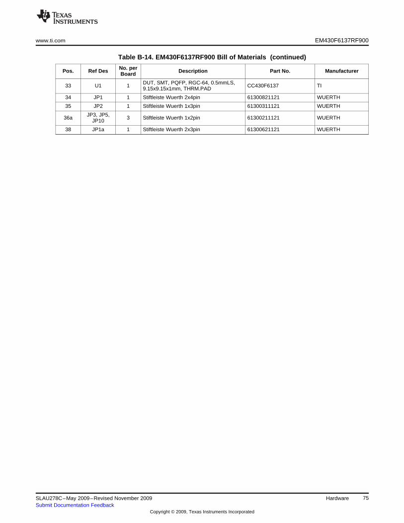
www.ti.com EM430F6137RF900
Table B-14. EM430F6137RF900 Bill of Materials (continued)
No. perPos. Ref Des Description Part No. ManufacturerBoard
DUT, SMT, PQFP, RGC-64, 0.5mmLS,33 U1 1 CC430F6137 TI9.15x9.15x1mm, THRM.PAD
34 JP1 1 Stiftleiste Wuerth 2x4pin 61300821121 WUERTH
35 JP2 1 Stiftleiste Wuerth 1x3pin 61300311121 WUERTH
JP3, JP5,36a 3 Stiftleiste Wuerth 1x2pin 61300211121 WUERTHJP10
38 JP1a 1 Stiftleiste Wuerth 2x3pin 61300621121 WUERTH
75SLAU278C–May 2009–Revised November 2009 HardwareSubmit Documentation Feedback
Copyright © 2009, Texas Instruments Incorporated
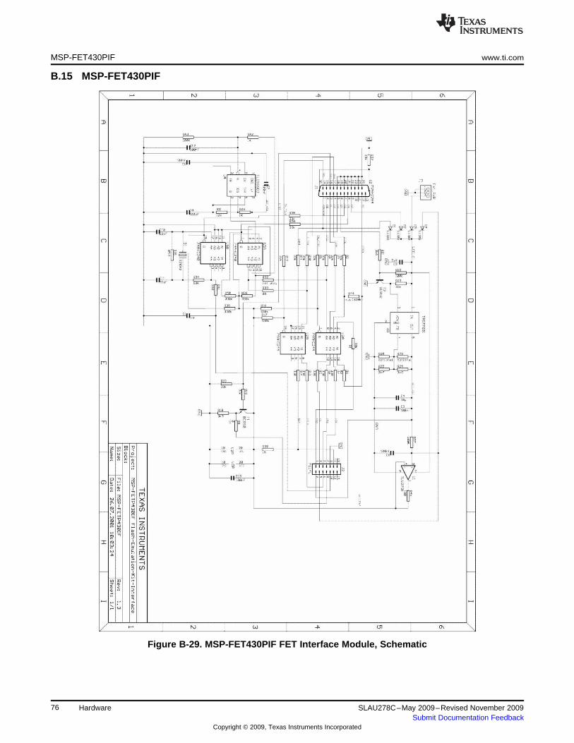
MSP-FET430PIF www.ti.com
B.15 MSP-FET430PIF
Figure B-29. MSP-FET430PIF FET Interface Module, Schematic
76 Hardware SLAU278C–May 2009–Revised November 2009Submit Documentation Feedback
Copyright © 2009, Texas Instruments Incorporated
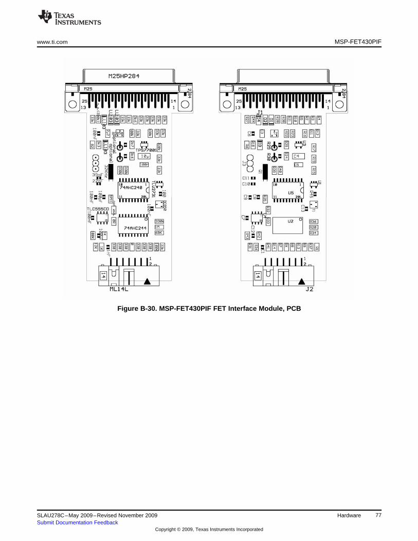
www.ti.com MSP-FET430PIF
Figure B-30. MSP-FET430PIF FET Interface Module, PCB
77SLAU278C–May 2009–Revised November 2009 HardwareSubmit Documentation Feedback
Copyright © 2009, Texas Instruments Incorporated
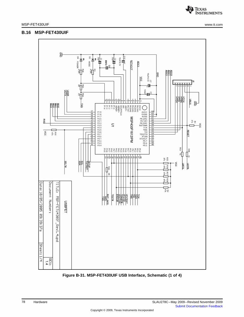
MSP-FET430UIF www.ti.com
B.16 MSP-FET430UIF
Figure B-31. MSP-FET430UIF USB Interface, Schematic (1 of 4)
78 Hardware SLAU278C–May 2009–Revised November 2009Submit Documentation Feedback
Copyright © 2009, Texas Instruments Incorporated
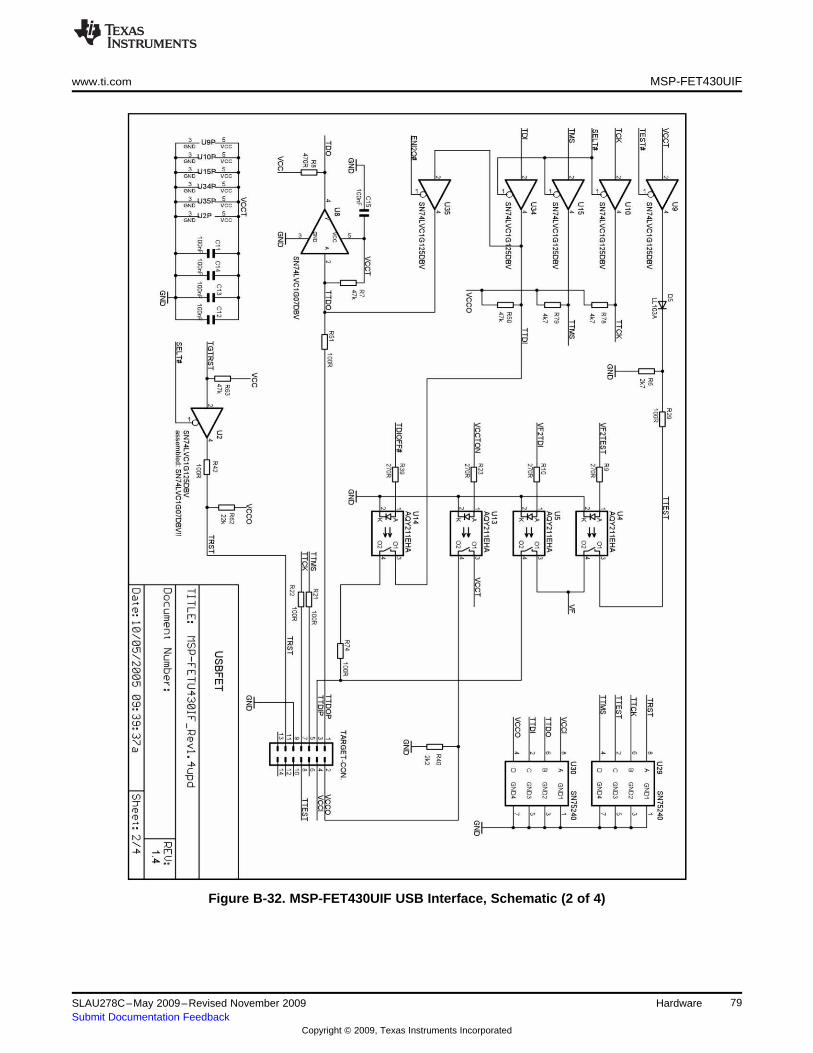
www.ti.com MSP-FET430UIF
Figure B-32. MSP-FET430UIF USB Interface, Schematic (2 of 4)
79SLAU278C–May 2009–Revised November 2009 HardwareSubmit Documentation Feedback
Copyright © 2009, Texas Instruments Incorporated
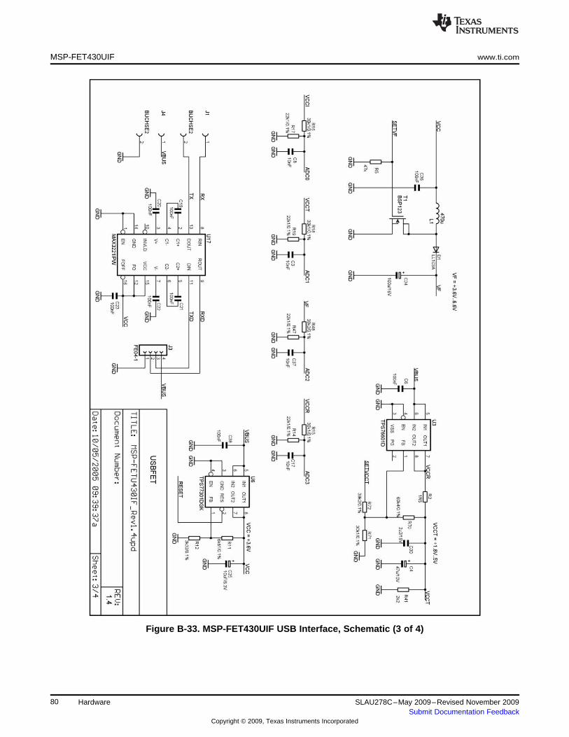
MSP-FET430UIF www.ti.com
Figure B-33. MSP-FET430UIF USB Interface, Schematic (3 of 4)
80 Hardware SLAU278C–May 2009–Revised November 2009Submit Documentation Feedback
Copyright © 2009, Texas Instruments Incorporated
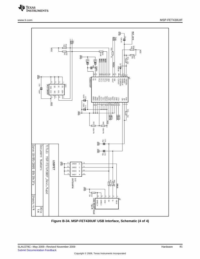
www.ti.com MSP-FET430UIF
Figure B-34. MSP-FET430UIF USB Interface, Schematic (4 of 4)
81SLAU278C–May 2009–Revised November 2009 HardwareSubmit Documentation Feedback
Copyright © 2009, Texas Instruments Incorporated
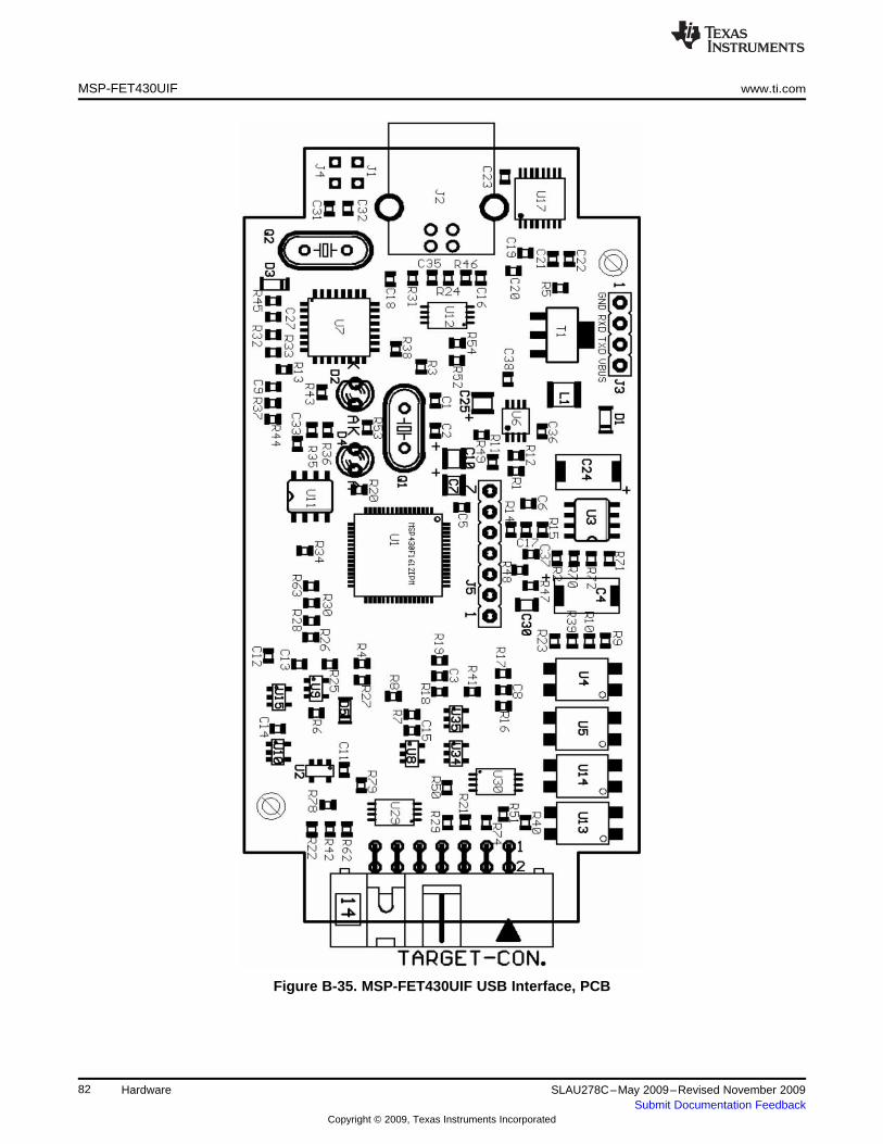
MSP-FET430UIF www.ti.com
Figure B-35. MSP-FET430UIF USB Interface, PCB
82 Hardware SLAU278C–May 2009–Revised November 2009Submit Documentation Feedback
Copyright © 2009, Texas Instruments Incorporated
www.ti.com MSP-FET430UIF
B.16.1 MSP-FET430UIF Revision History
Revision 1.3• Initial released hardware version
Assembly change on 1.3 (May 2005)• R29, R51, R42, R21, R22, R74: value changed from 330R to 100R
Changes 1.3 to 1.4 (Aug 2005)• J5: VBUS and RESET additionally connected• R29, R51, R42, R21, R22, R74: value changed from 330R to 100R• U1, U7: F1612 can reset TUSB3410; R44 = 0R added• TARGET-CON.: pins 6, 10, 12, 13, 14 disconnected from GND• Firmware-upgrade option through BSL: R49, R52, R53, R54 added; R49, R52 are currently DNP• Pullups on TCK and TMS: R78, R79 added• U2: Changed from SN75LVC1G125DBV to SN75LVC1G07DBV
NOTE: Using a locally powered target board with hardware revision 1.4
Using an MSP-FET430UIF interface hardware revision 1.4 with populated R62 in conjunctionwith a locally powered target board is not possible. In this case, the target device RESETsignal is pulled down by the FET tool. It is recommended to remove R62 to eliminate thisrestriction. This component is located close to the 14-pin connector on the MSP-FET430UIFPCB. See the schematic and PCB drawings in this document for the exact location of thiscomponent.
Assembly change on 1.4 (January 2006)• R62: not populated
83SLAU278C–May 2009–Revised November 2009 HardwareSubmit Documentation Feedback
Copyright © 2009, Texas Instruments Incorporated

84 Hardware SLAU278C–May 2009–Revised November 2009Submit Documentation Feedback
Copyright © 2009, Texas Instruments Incorporated
Appendix CSLAU278C–May 2009–Revised November 2009
Hardware Installation Guide
This section describes the hardware installation process of the following USB debug interfaces on a PCrunning Windows XP:
• MSP-FET430UIF• eZ430-F2013• eZ430-RF2500• eZ430-Chronos
The installation procedure for other supported versions of Windows is very similar and, therefore, notshown here.
Topic ........................................................................................................................... Page
C.1 Hardware Installation ......................................................................................... 86
85SLAU278C–May 2009–Revised November 2009 Hardware Installation GuideSubmit Documentation Feedback
Copyright © 2009, Texas Instruments Incorporated
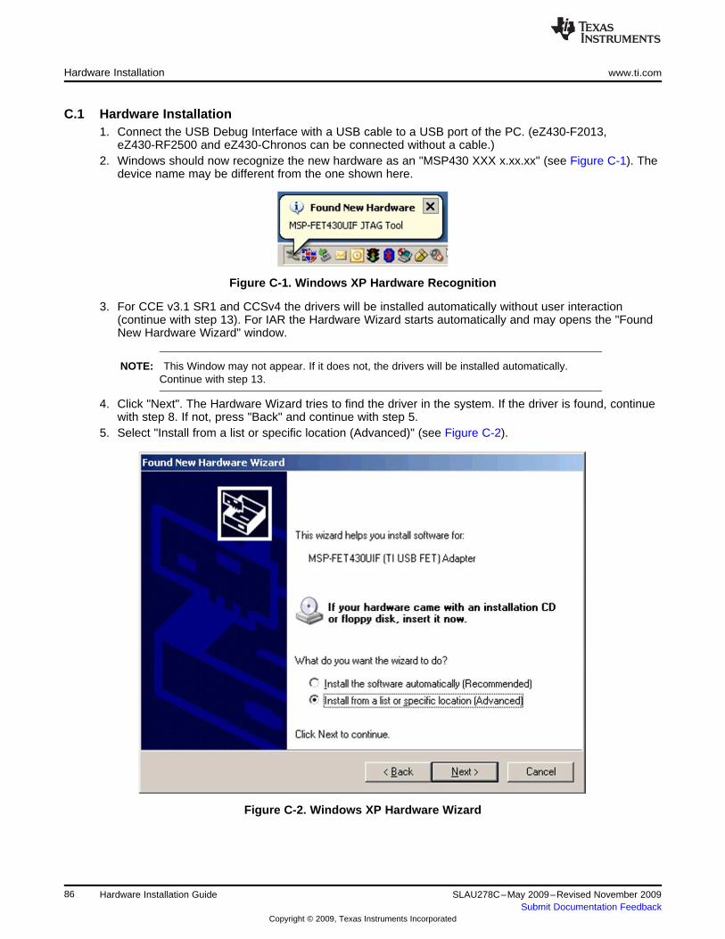
Hardware Installation www.ti.com
C.1 Hardware Installation1. Connect the USB Debug Interface with a USB cable to a USB port of the PC. (eZ430-F2013,
eZ430-RF2500 and eZ430-Chronos can be connected without a cable.)2. Windows should now recognize the new hardware as an "MSP430 XXX x.xx.xx" (see Figure C-1). The
device name may be different from the one shown here.
Figure C-1. Windows XP Hardware Recognition
3. For CCE v3.1 SR1 and CCSv4 the drivers will be installed automatically without user interaction(continue with step 13). For IAR the Hardware Wizard starts automatically and may opens the "FoundNew Hardware Wizard" window.
NOTE: This Window may not appear. If it does not, the drivers will be installed automatically.Continue with step 13.
4. Click "Next". The Hardware Wizard tries to find the driver in the system. If the driver is found, continuewith step 8. If not, press "Back" and continue with step 5.
5. Select "Install from a list or specific location (Advanced)" (see Figure C-2).
Figure C-2. Windows XP Hardware Wizard
86 Hardware Installation Guide SLAU278C–May 2009–Revised November 2009Submit Documentation Feedback
Copyright © 2009, Texas Instruments Incorporated
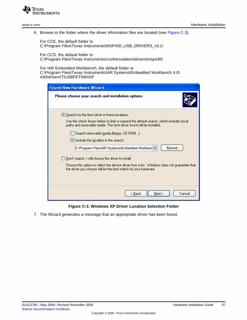
www.ti.com Hardware Installation
6. Browse to the folder where the driver information files are located (see Figure C-3).<br/>For CCE, the default folder is:C:\Program Files\Texas Instruments\MSP430_USB_DRIVERS_v3.1\<br/>For CCS, the default folder is:C:\Program Files\Texas Instruments\ccs4\emulation\drivers\msp430\<br/>For IAR Embedded Workbench, the default folder is:C:\Program Files\Texas Instruments\IAR Systems\Embedded Workbench 4.0\430\drivers\TIUSBFET\WinXP
Figure C-3. Windows XP Driver Location Selection Folder
7. The Wizard generates a message that an appropriate driver has been found.
87SLAU278C–May 2009–Revised November 2009 Hardware Installation GuideSubmit Documentation Feedback
Copyright © 2009, Texas Instruments Incorporated
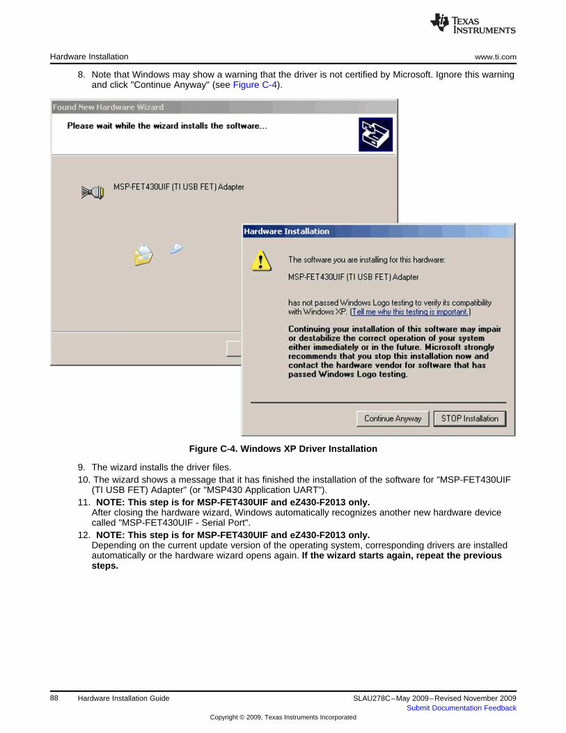
Hardware Installation www.ti.com
8. Note that Windows may show a warning that the driver is not certified by Microsoft. Ignore this warningand click "Continue Anyway" (see Figure C-4).
Figure C-4. Windows XP Driver Installation
9. The wizard installs the driver files.10. The wizard shows a message that it has finished the installation of the software for "MSP-FET430UIF
(TI USB FET) Adapter" (or "MSP430 Application UART").11. NOTE: This step is for MSP-FET430UIF and eZ430-F2013 only.
After closing the hardware wizard, Windows automatically recognizes another new hardware devicecalled "MSP-FET430UIF - Serial Port".
12. NOTE: This step is for MSP-FET430UIF and eZ430-F2013 only.Depending on the current update version of the operating system, corresponding drivers are installedautomatically or the hardware wizard opens again. If the wizard starts again, repeat the previoussteps.
88 Hardware Installation Guide SLAU278C–May 2009–Revised November 2009Submit Documentation Feedback
Copyright © 2009, Texas Instruments Incorporated
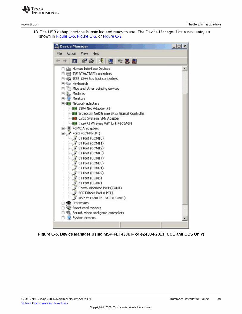
www.ti.com Hardware Installation
13. The USB debug interface is installed and ready to use. The Device Manager lists a new entry asshown in Figure C-5, Figure C-6, or Figure C-7.
Figure C-5. Device Manager Using MSP-FET430UIF or eZ430-F2013 (CCE and CCS Only)
89SLAU278C–May 2009–Revised November 2009 Hardware Installation GuideSubmit Documentation Feedback
Copyright © 2009, Texas Instruments Incorporated
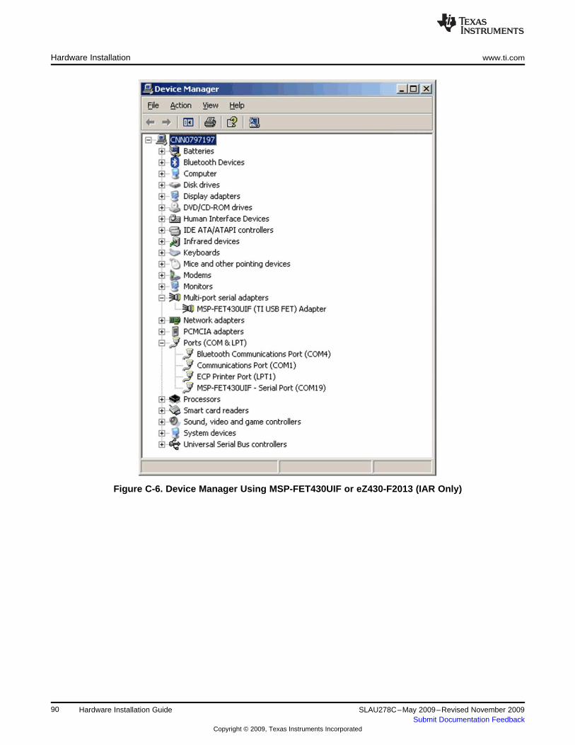
Hardware Installation www.ti.com
Figure C-6. Device Manager Using MSP-FET430UIF or eZ430-F2013 (IAR Only)
90 Hardware Installation Guide SLAU278C–May 2009–Revised November 2009Submit Documentation Feedback
Copyright © 2009, Texas Instruments Incorporated
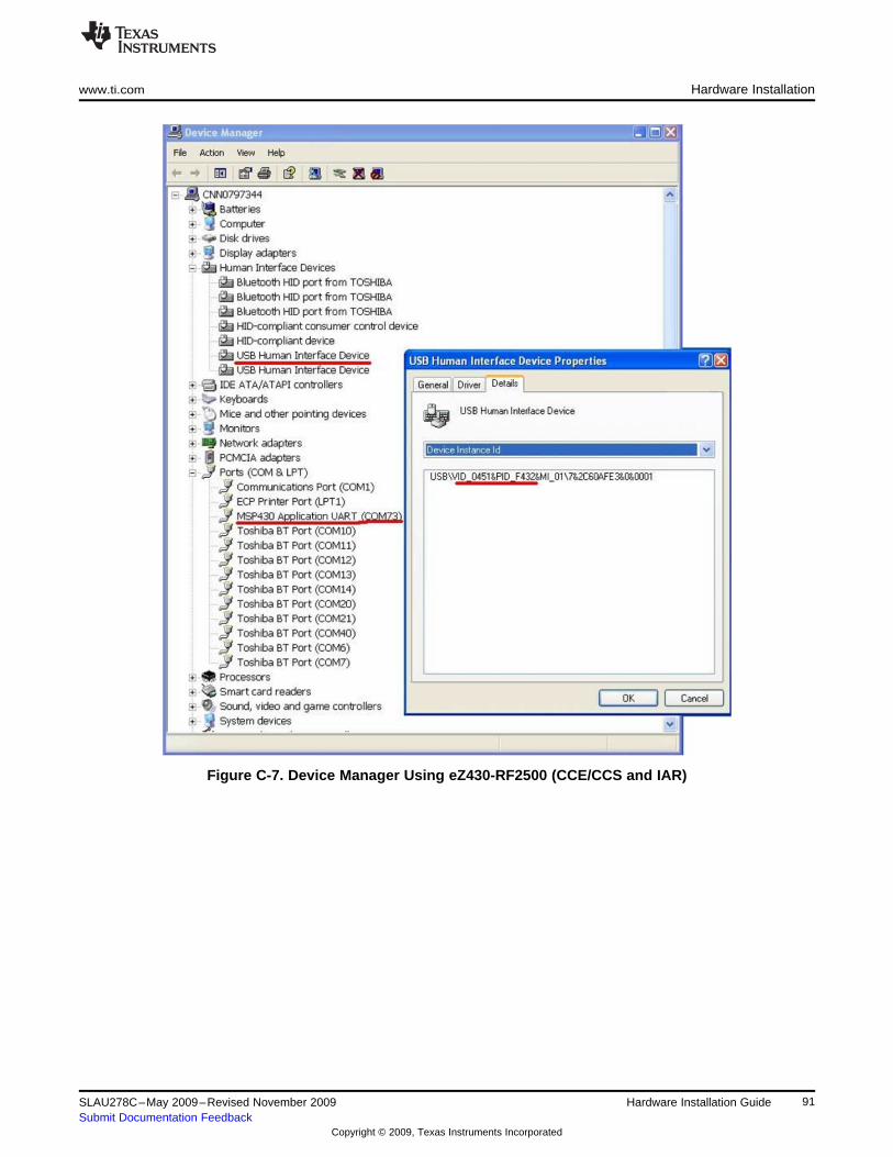
www.ti.com Hardware Installation
Figure C-7. Device Manager Using eZ430-RF2500 (CCE/CCS and IAR)
91SLAU278C–May 2009–Revised November 2009 Hardware Installation GuideSubmit Documentation Feedback
Copyright © 2009, Texas Instruments Incorporated
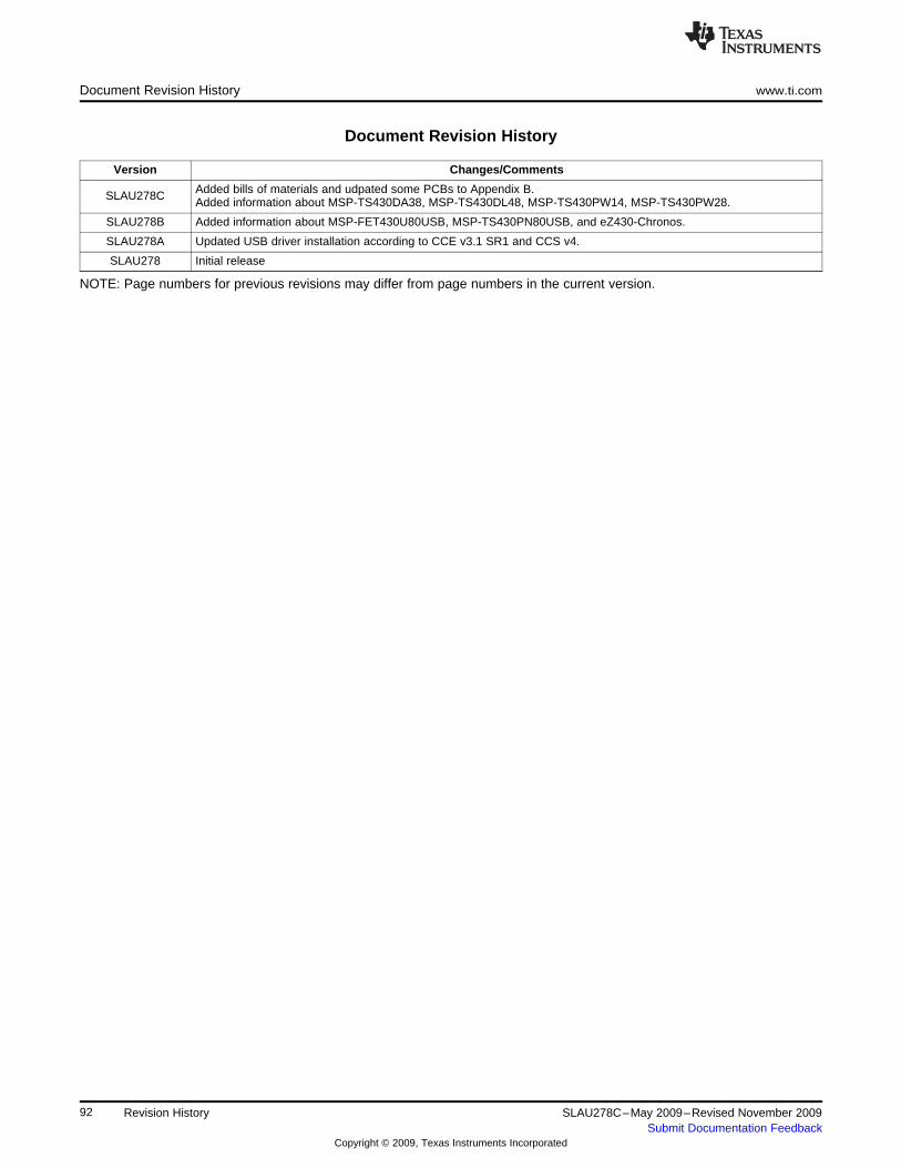
Document Revision History www.ti.com
Document Revision History
Version Changes/Comments
Added bills of materials and udpated some PCBs to Appendix B.SLAU278C Added information about MSP-TS430DA38, MSP-TS430DL48, MSP-TS430PW14, MSP-TS430PW28.
SLAU278B Added information about MSP-FET430U80USB, MSP-TS430PN80USB, and eZ430-Chronos.
SLAU278A Updated USB driver installation according to CCE v3.1 SR1 and CCS v4.
SLAU278 Initial release
NOTE: Page numbers for previous revisions may differ from page numbers in the current version.
92 Revision History SLAU278C–May 2009–Revised November 2009Submit Documentation Feedback
Copyright © 2009, Texas Instruments Incorporated

EVALUATION BOARD/KIT IMPORTANT NOTICE
Texas Instruments (TI) provides the enclosed product(s) under the following conditions:
This evaluation board/kit is intended for use for ENGINEERING DEVELOPMENT, DEMONSTRATION, OR EVALUATION PURPOSESONLY and is not considered by TI to be a finished end-product fit for general consumer use. Persons handling the product(s) must haveelectronics training and observe good engineering practice standards. As such, the goods being provided are not intended to be completein terms of required design-, marketing-, and/or manufacturing-related protective considerations, including product safety and environmentalmeasures typically found in end products that incorporate such semiconductor components or circuit boards. This evaluation board/kit doesnot fall within the scope of the European Union directives regarding electromagnetic compatibility, restricted substances (RoHS), recycling(WEEE), FCC, CE or UL, and therefore may not meet the technical requirements of these directives or other related directives.
Should this evaluation board/kit not meet the specifications indicated in the User’s Guide, the board/kit may be returned within 30 days fromthe date of delivery for a full refund. THE FOREGOING WARRANTY IS THE EXCLUSIVE WARRANTY MADE BY SELLER TO BUYERAND IS IN LIEU OF ALL OTHER WARRANTIES, EXPRESSED, IMPLIED, OR STATUTORY, INCLUDING ANY WARRANTY OFMERCHANTABILITY OR FITNESS FOR ANY PARTICULAR PURPOSE.
The user assumes all responsibility and liability for proper and safe handling of the goods. Further, the user indemnifies TI from all claimsarising from the handling or use of the goods. Due to the open construction of the product, it is the user’s responsibility to take any and allappropriate precautions with regard to electrostatic discharge.
EXCEPT TO THE EXTENT OF THE INDEMNITY SET FORTH ABOVE, NEITHER PARTY SHALL BE LIABLE TO THE OTHER FOR ANYINDIRECT, SPECIAL, INCIDENTAL, OR CONSEQUENTIAL DAMAGES.
TI currently deals with a variety of customers for products, and therefore our arrangement with the user is not exclusive.
TI assumes no liability for applications assistance, customer product design, software performance, or infringement of patents orservices described herein.
Please read the User’s Guide and, specifically, the Warnings and Restrictions notice in the User’s Guide prior to handling the product. Thisnotice contains important safety information about temperatures and voltages. For additional information on TI’s environmental and/orsafety programs, please contact the TI application engineer or visit www.ti.com/esh.
No license is granted under any patent right or other intellectual property right of TI covering or relating to any machine, process, orcombination in which such TI products or services might be or are used.
FCC Warning
This evaluation board/kit is intended for use for ENGINEERING DEVELOPMENT, DEMONSTRATION, OR EVALUATION PURPOSESONLY and is not considered by TI to be a finished end-product fit for general consumer use. It generates, uses, and can radiate radiofrequency energy and has not been tested for compliance with the limits of computing devices pursuant to part 15 of FCC rules, which aredesigned to provide reasonable protection against radio frequency interference. Operation of this equipment in other environments maycause interference with radio communications, in which case the user at his own expense will be required to take whatever measures maybe required to correct this interference.
IMPORTANT NOTICETexas Instruments Incorporated and its subsidiaries (TI) reserve the right to make corrections, modifications, enhancements, improvements,and other changes to its products and services at any time and to discontinue any product or service without notice. Customers shouldobtain the latest relevant information before placing orders and should verify that such information is current and complete. All products aresold subject to TI’s terms and conditions of sale supplied at the time of order acknowledgment.TI warrants performance of its hardware products to the specifications applicable at the time of sale in accordance with TI’s standardwarranty. Testing and other quality control techniques are used to the extent TI deems necessary to support this warranty. Except wheremandated by government requirements, testing of all parameters of each product is not necessarily performed.TI assumes no liability for applications assistance or customer product design. Customers are responsible for their products andapplications using TI components. To minimize the risks associated with customer products and applications, customers should provideadequate design and operating safeguards.TI does not warrant or represent that any license, either express or implied, is granted under any TI patent right, copyright, mask work right,or other TI intellectual property right relating to any combination, machine, or process in which TI products or services are used. Informationpublished by TI regarding third-party products or services does not constitute a license from TI to use such products or services or awarranty or endorsement thereof. Use of such information may require a license from a third party under the patents or other intellectualproperty of the third party, or a license from TI under the patents or other intellectual property of TI.Reproduction of TI information in TI data books or data sheets is permissible only if reproduction is without alteration and is accompaniedby all associated warranties, conditions, limitations, and notices. Reproduction of this information with alteration is an unfair and deceptivebusiness practice. TI is not responsible or liable for such altered documentation. Information of third parties may be subject to additionalrestrictions.Resale of TI products or services with statements different from or beyond the parameters stated by TI for that product or service voids allexpress and any implied warranties for the associated TI product or service and is an unfair and deceptive business practice. TI is notresponsible or liable for any such statements.TI products are not authorized for use in safety-critical applications (such as life support) where a failure of the TI product would reasonablybe expected to cause severe personal injury or death, unless officers of the parties have executed an agreement specifically governingsuch use. Buyers represent that they have all necessary expertise in the safety and regulatory ramifications of their applications, andacknowledge and agree that they are solely responsible for all legal, regulatory and safety-related requirements concerning their productsand any use of TI products in such safety-critical applications, notwithstanding any applications-related information or support that may beprovided by TI. Further, Buyers must fully indemnify TI and its representatives against any damages arising out of the use of TI products insuch safety-critical applications.TI products are neither designed nor intended for use in military/aerospace applications or environments unless the TI products arespecifically designated by TI as military-grade or "enhanced plastic." Only products designated by TI as military-grade meet militaryspecifications. Buyers acknowledge and agree that any such use of TI products which TI has not designated as military-grade is solely atthe Buyer's risk, and that they are solely responsible for compliance with all legal and regulatory requirements in connection with such use.TI products are neither designed nor intended for use in automotive applications or environments unless the specific TI products aredesignated by TI as compliant with ISO/TS 16949 requirements. Buyers acknowledge and agree that, if they use any non-designatedproducts in automotive applications, TI will not be responsible for any failure to meet such requirements.Following are URLs where you can obtain information on other Texas Instruments products and application solutions:Products ApplicationsAmplifiers amplifier.ti.com Audio www.ti.com/audioData Converters dataconverter.ti.com Automotive www.ti.com/automotiveDLP® Products www.dlp.com Broadband www.ti.com/broadbandDSP dsp.ti.com Digital Control www.ti.com/digitalcontrolClocks and Timers www.ti.com/clocks Medical www.ti.com/medicalInterface interface.ti.com Military www.ti.com/militaryLogic logic.ti.com Optical Networking www.ti.com/opticalnetworkPower Mgmt power.ti.com Security www.ti.com/securityMicrocontrollers microcontroller.ti.com Telephony www.ti.com/telephonyRFID www.ti-rfid.com Video & Imaging www.ti.com/videoRF/IF and ZigBee® Solutions www.ti.com/lprf Wireless www.ti.com/wireless
Mailing Address: Texas Instruments, Post Office Box 655303, Dallas, Texas 75265Copyright © 2009, Texas Instruments Incorporated