Embed Size (px)
Citation preview

22
© UCLES 2014 0625/61/O/N/14 [Turn over© UCLES 2014 0625/61/O/N/14
MS.RAJA ELGADY/LIGHT PAPER 61 The IGCSE class is investigating the reflection of light by a plane mirror. Fig. 1.1 shows a student’s
ray-trace sheet.
mirror
Fig. 1.1
(a) On Fig. 1.1, draw a normal to the centre of the mirror. [1]
(b) On Fig. 1.1, draw an incident ray at 30° to the normal and to the left of the normal. [1]
(c) Fig. 1.2 shows a diagram of a ray box.
lamp hole
ray box
Fig. 1.2
On Fig. 1.1, draw the ray box in a suitable position to produce the incident ray that you havedrawn. [1]
(d) On Fig. 1.1, draw a reflected ray in the position you would expect it to be using the incidentray that you have drawn. [1]
33
© UCLES 2014 0625/61/O/N/14 [Turn over© UCLES 2014 0625/61/O/N/14
MS.RAJA ELGADY/LIGHT PAPER 6(e) State two precautions that you could take in this experiment to obtain reliable results.
1. ............................................................................................................................. ..................
...................................................................................................................................................
2. ............................................................................................................................. ..................
............................................................................................................................. ......................[2]
[Total: 6]

© UCLES 2014 0625/61/O/N/14 [Turn over© UCLES 2014 0625/61/O/N/14
88MS.RAJA ELGADY/LIGHT PAPER 62- The IGCSE class is determining the magnification of an image produced by a lens.
The apparatus is shown in Fig. 4.1.illuminated uobject v
lens screen
bench
Fig. 4.1
(a) (i) On Fig. 4.1, measure and record in mm the distance u from the illuminated object to thecentre of the lens.
u = ............................................... mm
(ii) On Fig. 4.1, measure and record in mm the distance v from the centre of the lens to thescreen.
(b) Calculate the ratio v .u
v = ............................................... mm[1]
vu = ................................................. [1]
(c) The diagram is drawn one tenth of actual size.
(i) Calculate the actual distance U from the illuminated object to the centre of the lens.
U = ............................................... mm
(ii) Calculate the actual distance V from the centre of the lens to the screen.
V = ............................................... mm[1]
(d) The student measures the height h from the top to the bottom of the image on the screen.
h = .......................4....5...................... cm

© UCLES 2014 0625/61/O/N/14 [Turn over© UCLES 2014 0625/61/O/N/14
99MS.RAJA ELGADY/LIGHT PAPER 6(i) On Fig. 4.2, measure the height x of the illuminated object.
illuminated object
Fig. 4.2 (full size)
(ii) Calculate h .x
x = ......................................................
hx = ......................................................
[1]
(e) The magnification m of the image is given by the equation m =h
. The student suggests thatV x
the ratio U also gives the magnification m. State whether the results support this suggestion
and justify your answer by reference to the results.
statement ..................................................................................................................................
justification ............................................................................................................................. ...
...................................................................................................................................................[2]
(f) State two precautions that you could take in this experiment to obtain reliable results.
1. ...............................................................................................................................................
............................................................................................................................. ......................
2. ................................................................................................................................... ............
..................................................................................................................... ..............................[2]
(g) The image on the screen in this experiment is magnified and dimmer than the object.
State one other difference that you would expect to see between the image and the illuminatedobject.
.............................................................................................................................................. .[1]
(h) Suggest one precaution that you would take in this experiment in order to focus the image asclearly as possible.

© UCLES 2014 0625/61/O/N/14 [Turn over© UCLES 2014 0625/61/O/N/14
1010MS.RAJA ELGADY/LIGHT PAPER 6
............................................................................................................................................ .......
.......................................................................................................................... .....................[1]
[Total: 10]

© UCLES 2014 0625/61/O/N/14 [Turn over© UCLES 2014 0625/61/O/N/14
1111MS.RAJA ELGADY/LIGHT PAPER 6
3- The class is investigating the refraction of light passing through a transparent block.
Fig. 4.1 shows a student’s ray-trace sheet.
A B
ray–tracesheet D C
P3
P4
eye

© UCLES 2014 0625/61/O/N/14 [Turn over© UCLES 2014 0625/61/O/N/14
1212MS.RAJA ELGADY/LIGHT PAPER 6
Fig. 4.1
© UCLES 2014 0625/61/O/N/14 [Turn over© UCLES 2014 0625/61/O/N/14
1313MS.RAJA ELGADY/LIGHT PAPER 6
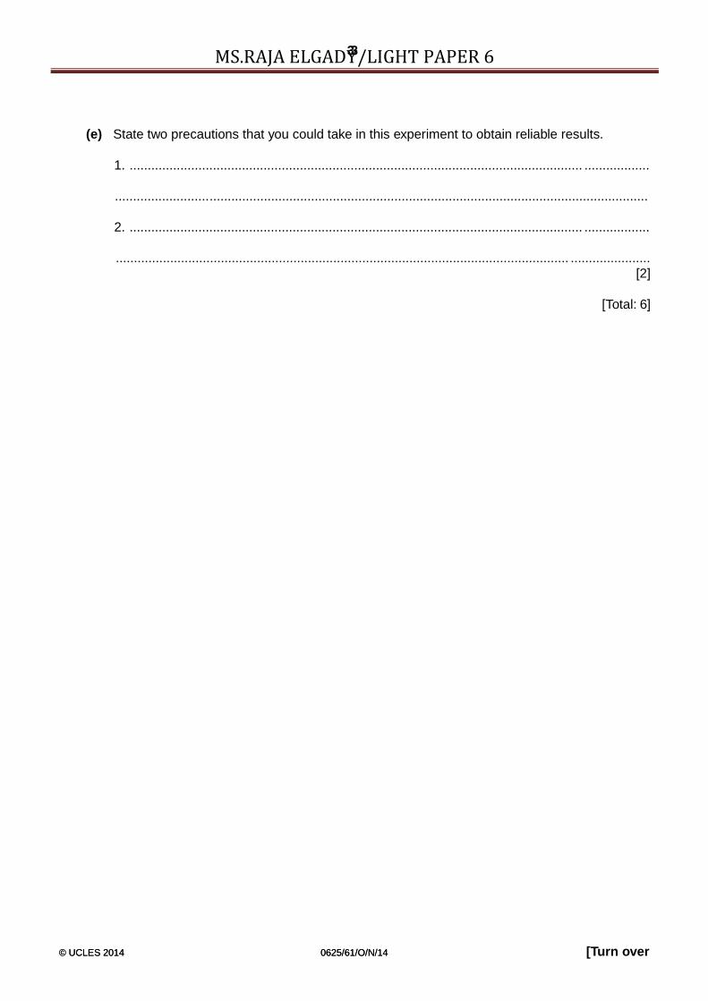
A student draws the outline ABCD of a transparent block.
(a) (i) Draw a normal NL at the centre of side AB. Label the point E where the normal crossesAB. Label the point M where the normal crosses CD.
(ii) Draw a line GH, parallel to AB and 6.0cm above AB. Label the point J where the normalcrosses GH.
(iii) Draw a line, starting at E, to the left of the normal and at an angle of incidence i = 30° tothe normal. Label the point F where the line meets GH.
(b) The student places two pins P1 and P2 on the line FE.[3]
On Fig. 4.1, label suitable positions for pins P1 and P2. [1]
(c) The student observes the images of P1 and P2 through side CD of the block so that theimages of P1 and P2 appear one behind the other.
She places two pins P3 and P4 between her eye and the block so that P3 and P4, and theimages of P1 and P2 seen through the block, appear one behind the other. The positions of P3and P4 are shown on Fig. 4.1.
(i) Draw a line joining the positions of P3 and P4. Continue the line until it meets CD andlabel this point K.
(ii) Draw the line KE.[1]
(d) (i) Measure and record the length a between points F and J.
a = ...............................................................
(ii) Measure and record the length b between points F and E.
b = ...............................................................
(iii) Measure and record the length c between points E and K.
c = ...............................................................
(iv) Measure and record the length d between points M and K.
d = ...............................................................[1]
ac(v) Calculate n, the refractive index of the material of the block, using the equation n = bd .
n = ...........................................................[1]

© UCLES 2014 0625/61/O/N/14 [Turn over© UCLES 2014 0625/61/O/N/14
1414MS.RAJA ELGADY/LIGHT PAPER 6
(e) Suggest one precaution that you would take with this experiment to obtain reliable results.
............................................................................................................................. ......................
.............................................................................................................................. .....................
............................................................................................................ ...................................[1]
(f) Fig. 4.2 shows a ray box.
lamp slit
Fig. 4.2
This experiment can be carried out using a ray box instead of the pins.
On Fig. 4.1, draw a ray box in a suitable position for this experiment. [1]
[Total: 9]

© UCLES 2014 0625/61/O/N/14 [Turn over© UCLES 2014 0625/61/O/N/14
1010MS.RAJA ELGADY/LIGHT PAPER 64- The IGCSE class is investigating reflection using a plane mirror.
Fig. 5.1 shows a student’s ray-trace sheet with a line MR drawn on it. In the experiment thereflecting face of a mirror is placed vertically on the line MR. The additional dashed line shows asecond mirror position.
ray-trace sheetN
MB ș R
P3
P4
L
Fig. 5.1
(a) NL is a normal to line MR. Draw a line 8.0 cm long from B at an angle of incidence i = 30° tothe normal, below MR and to the left of the normal. Label the end of this line A. [1]
(b) The student places two pins, P1 and P2, on line AB a suitable distance apart for this raytracing experiment. He views the images of pins P1 and P2 in the mirror and places two pinsP3 and P4 so that pins P3 and P4, and the images of P2 and P1, all appear exactly one behindthe other. The positions of P3 and P4 are shown in Fig. 5.1.
(i) Draw the line joining the positions of P3 and P4. Extend the line until it meets NL.
(ii) Measure the angle α0 between NL and the line joining the positions of P3 and P4. At thisstage the angle θ between the mirror and line MR is 0°.
α0 = .................................................... [2
© UCLES 2014 0625/61/O/N/14 [Turn over© UCLES 2014 0625/61/O/N/14
1111MS.RAJA ELGADY/LIGHT PAPER 6G .................................................... [2]
© UCLES 2014 0625/61/O/N/14 [Turn over© UCLES 2014 0625/61/O/N/14
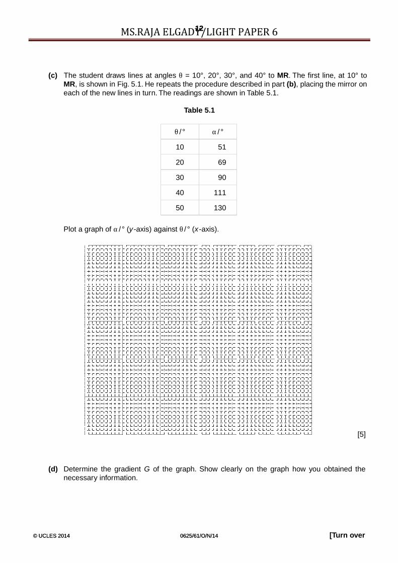
1212MS.RAJA ELGADY/LIGHT PAPER 6(c) The student draws lines at angles θ = 10°, 20°, 30°, and 40° to MR. The first line, at 10° to
MR, is shown in Fig. 5.1. He repeats the procedure described in part (b), placing the mirror oneach of the new lines in turn. The readings are shown in Table 5.1.
Table 5.1
θ / ° α / °
10 51
20 69
30 90
40 111
50 130
Plot a graph of α / ° (y-axis) against θ / ° (x-axis).
[5]
(d) Determine the gradient G of the graph. Show clearly on the graph how you obtained thenecessary information.

© UCLES 2014 0625/61/O/N/14 [Turn over© UCLES 2014 0625/61/O/N/14
1313MS.RAJA ELGADY/LIGHT PAPER 6G = ............................................... [2]

© UCLES 2014 0625/61/O/N/14 [Turn over© UCLES 2014 0625/61/O/N/14
66MS.RAJA ELGADY/LIGHT PAPER 6(e) In this experiment, when the mirror is moved though an angle θ, the reflected
ray moves through an angle (α – α0).
Table 5.2
θ / ° α / ° (α – α0)/°
10 51
20 69
30 90
40 111
50 130
(i) Complete Table 5.2.
(ii) Suggest the relationship between (α – α0) and θ. You may express therelationship in words or as an equation.
............................................................................................................................. ..............
.................................................................................. .........................................................[1]
(f) State one precaution, to improve accuracy, which you would take in this experiment.
...................................................................................................... .............................................
............................................................................................................................. ..................[1]
[Total: 12]

© UCLES 2014 0625/61/O/N/14 [Turn over© UCLES 2014 0625/61/O/N/14
77MS.RAJA ELGADY/LIGHT PAPER 65- The class is investigating reflection using a plane mirror.
Fig. 3.1. shows a student’s ray-trace sheet.
M R
P3
ray-tracesheet
Fig. 3.1

© UCLES 2014 0625/61/O/N/14 [Turn over© UCLES 2014 0625/61/O/N/14
66MS.RAJA ELGADY/LIGHT PAPER 6P4
eye
ray-tracesheet
Fig. 3.1

© UCLES 2014 0625/61/O/N/14 [Turn over© UCLES 2014 0625/61/O/N/14
77MS.RAJA ELGADY/LIGHT PAPER 6(a) The student draws the line MR to mark the position of a plane mirror.
(i) Draw a normal to this line that passes through its centre. Label the normal NL. Label thepoint at which NL crosses MR with the letter A.
(ii) Draw a line 8.0cm long from A at an angle of incidence i = 30° to the normal, below MRand to the left of the normal. Label the end of this line B.
[3]
(b) The student places a pin P1 at point B. He places a second pin P2 on line AB.
Label a position X on line AB to show a suitable position for pin P2. [1]
(c) He views the images of pins P1 and P2 from the direction indicated by the eye in Fig. 3.1. Heplaces two pins P3 and P4, a suitable distance apart, so that pins P3 and P4, and the images of P2and P1, all appear exactly one behind the other.The positions of P3 and P4 are shown in Fig. 3.1.
(i) Draw the line joining the positions of P3 and P4. Extend the line until it meets NL.
(ii) Measure the angle r between NL and the line joining the positions of P3 and P4.
r = ...............................................................[2]
(d) State two precautions that you would take in this experiment in order to obtain reliablereadings.
1. ............................................................................................................................. ..................
.............................................................................................................. .....................................
2. ............................................................................................................................. ..................
...................................................................................................................................................[2]
(e) A student has done this experiment very carefully, taking these precautions.
She is disappointed to find that her line for the reflected ray is not exactly where she predictsfrom the theory.
Suggest a practical reason for this.
............................................................................................................................. ......................
.............................................................................................................................................. .[1]
[Total: 9]
© UCLES 2014 0625/61/O/N/14 [Turn over© UCLES 2014 0625/61/O/N/14
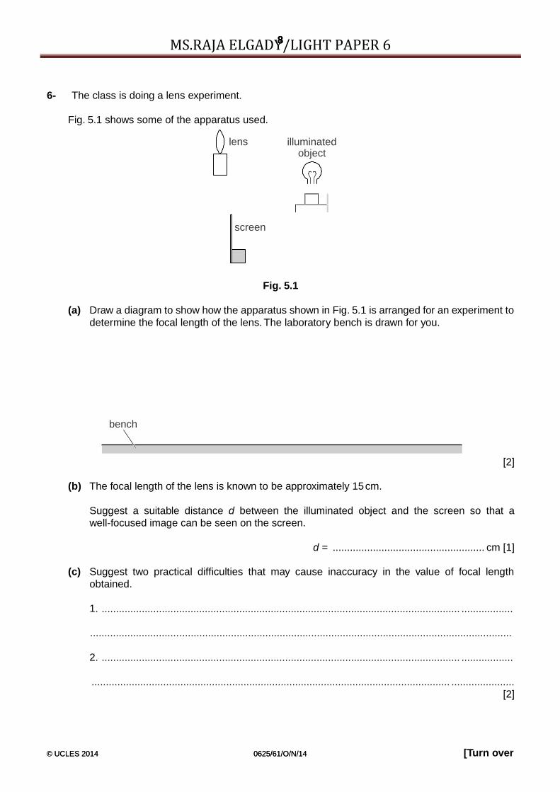
88MS.RAJA ELGADY/LIGHT PAPER 66- The class is doing a lens experiment.
Fig. 5.1 shows some of the apparatus used.
lens
screen
illuminatedobject
Fig. 5.1
(a) Draw a diagram to show how the apparatus shown in Fig. 5.1 is arranged for an experiment todetermine the focal length of the lens. The laboratory bench is drawn for you.
bench
[2]
(b) The focal length of the lens is known to be approximately 15cm.
Suggest a suitable distance d between the illuminated object and the screen so that awell-focused image can be seen on the screen.
d = ..................................................... cm [1]
(c) Suggest two practical difficulties that may cause inaccuracy in the value of focal lengthobtained.
1. ............................................................................................................................. ..................
...................................................................................................................................................
2. ............................................................................................................................. ..................
............................................................................................................................. ......................[2]

© UCLES 2014 0625/61/O/N/14 [Turn over© UCLES 2014 0625/61/O/N/14
10 ForExaminer’s
UseMS.RAJA ELGADY/LIGHT PAPER 6
(d) Fig. 5.2 shows the shape of the illuminated object.
Fig. 5.2
In the space below, draw a diagram to show the focused image that you would expect to see onthe screen. [1]
[Total: 6]
7- A student investigates the refraction of light through a transparent block.
He places the transparent block on a sheet of plain paper, largest face down, and draws aline round the block. He draws a line to represent an incident ray and places two pins Wand X in the line. Fig. 5.1 shows the outline of the block and the incident ray.

© UCLES 2014 0625/61/O/N/14 [Turn over© UCLES 2014 0625/61/O/N/14
11 ForExaminer’s
UseMS.RAJA ELGADY/LIGHT PAPER 6
W
A X B
D C
Fig. 5.1
(a) On Fig. 5.1, draw a normal to line AB at the point where the incident ray meets theblock. The incident ray is drawn on the diagram. The positions of the two pins W and Xthat mark the incident ray are shown. [1]
(b) Measure the angle of incidence i.
i = ........................................................ [1]
(c) Draw in the refracted ray with an angle of refraction of 20°. Continue this line until itmeets the line CD. [2]
(d) The ray emerges from the block in a direction that is parallel to the incident ray. Draw inthis emergent ray. [2]
(e) Two pins Y and Z are placed so that the pins W and X, viewed through the block, andthe pins Y and Z all appear exactly in line with each other. Mark on the diagram, withthe letters Y and Z, where you would place these two pins. [2]

12 ForExaminer’s
Use
© UCLES 2006 0625/06/O/N/06
MS.RAJA ELGADY/LIGHT PAPER 68- The IGCSE class is investigating reflection in a plane mirror. Fig. 3.1 shows a ray diagram
that a student is constructing.
paper
GE F
mirror
J K
eye
Fig. 3.1
7 For
[Turn over© UCLES 2006 0625/06/O/N/06
MS.RAJA ELGADY/LIGHT PAPER 6

8 For
[Turn over© UCLES 2006 0625/06/O/N/06
MS.RAJA ELGADY/LIGHT PAPER 6(a) (i) Draw a normal GH to line EF.
(ii) Mark a point A on line GJ so that the distance AG is 11.5 cm.
(iii) Measure the angle of incidence i between line GJ and the normal.
i = ..................................................... [3]
(b) The student pushes two pins into the paper on line GJ, one at point A, and the other at a point Bnearer to the mirror. He views the images of the pins from the direction indicated in Fig. 3.1. Hethen pushes in two pins on line GK between his eye and the mirror so that these two pins andthe images of the pins on line GJ appear exactly one behind the other.
(i) On Fig. 3.1, mark suitable positions for the pins on lines GJ and GK. Label the markswith letters B, C and D.
(ii) To obtain an accurate result for this experiment, would you view the tops, bases or centralparts of the pins when lining them up? Give a reason for your answer.
I would view .............................................................................................................. reason
......................................................................................................................
.............................................................................................................................. ....
............................................................................................................................ [3]

9 For
[Turn over© UCLES 2006 0625/06/O/N/06
MS.RAJA ELGADY/LIGHT PAPER 6
P2F
G
P3
9- The IGCSE class is determining the refractive index of the material of a transparent block.Fig. 3.1. shows the drawing that a student makes.
E
P1 N
A B
D C
N P4
sheet ofplain paper
eye
Fig. 3.1
10
For
[Turn over© UCLES 2006 0625/06/O/N/06
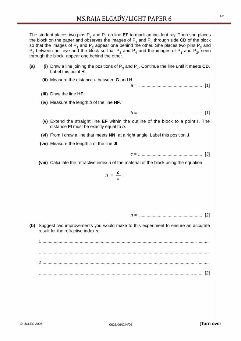
MS.RAJA ELGADY/LIGHT PAPER 6The student places two pins P1 and P2 on line EF to mark an incident ray. Then she placesthe block on the paper and observes the images of P1 and P2 through side CD of the blockso that the images of P1 and P2 appear one behind the other. She places two pins P3 andP4 between her eye and the block so that P3 and P4 and the images of P1 and P2, seenthrough the block, appear one behind the other.
(a) (i) Draw a line joining the positions of P3 and P4. Continue the line until it meets CD.Label this point H.
(ii) Measure the distance a between G and H.
(iii) Draw the line HF.
(iv) Measure the length b of the line HF.
a = ................................................... [1]
b = ................................................... [1]
(v) Extend the straight line EF within the outline of the block to a point I. Thedistance FI must be exactly equal to b.
(vi) From I draw a line that meets NN at a right angle. Label this position J.
(vii) Measure the length c of the line JI.
c = .................................................... [3]
(viii) Calculate the refractive index n of the material of the block using the equation
cn = –– .
a
n = ................................................... [2]
(b) Suggest two improvements you would make to this experiment to ensure an accurateresult for the refractive index n.
1 ............................................................................................................................ ...........
............................................................................................................................. .............
2 ............................................................................................................................ ...........
............................................................................................................................. ....... [2]

11
For
[Turn over© UCLES 2006 0625/06/O/N/06
MS.RAJA ELGADY/LIGHT PAPER 69-- An IGCSE student is investigating the reflection of light by a plane mirror.
M M'
A B
card
Fig. 4.1
On Fig. 4.1, the line MM' shows the position of the mirror that is standing on a sheet ofpaper. The reflecting surface of the mirror is vertical. AB is a card that is standing verticallyand is parallel to the reflecting surface of the mirror.
(a) Draw a normal to the mirror such that the edge B of the card lies on the normal. [1]
(b) Measure the distance x along the normal between the line MM' and the edge B of thecard.
x = ......................................................... [1]
(c) Draw a line from the edge A of the card to the point where the normal meets the lineMM'. This represents an incident ray from the edge of the card. [1]
(d) Measure the angle i between the incident ray and the normal.
i = .......................................................... [1]

12
For
[Turn over© UCLES 2006 0625/06/O/N/06
MS.RAJA ELGADY/LIGHT PAPER 6x(e) Calculate the ratio ––y where y = 5.0 cm, the length of the card.
x–– = ................................................... [2]y
(f) The angle of reflection is to be determined as accurately as possible. On Fig. 4.1, markwith the letters X, Y and Z the points where the student would place three pins in orderto plot the reflected ray. [4]

13
For
[Turn over© UCLES 2006 0625/06/O/N/06
MS.RAJA ELGADY/LIGHT PAPER 610- A student is determining a quantity called the refractive index of the material of a transparent
block.
Fig. 4.1 shows the ray-tracing sheet that the student is producing. ABCD is the outline of thetransparent block, drawn on the ray-tracing sheet.
ForExaminer’s
Use
A B
D CP3
P4
Fig. 4.1
(a) (i) Draw the normal NN' to side AB, extended to cross side DC, so that the normal is2.0cm from A. Label the point F where NN' crosses AB. Label the point G whereNN' crosses DC.
(ii) Draw the line EF at an angle of 30° to the normal and to the left of the normal NN'.E is a point outside the block and above AB on the ray-tracing sheet.
[3]
14
For
[Turn over© UCLES 2006 0625/06/O/N/06
MS.RAJA ELGADY/LIGHT PAPER 6

15
For
[Turn over© UCLES 2006 0625/06/O/N/06
MS.RAJA ELGADY/LIGHT PAPER 6(b) Read the following passage, taken from the student’s notebook and
then answer the questions that follow.
I placed two pins P1 and P2 on line EF.I observed the images of P1 and P2 through side CD of theblock so thatthe images of P1 and P2 appeared one behind the other. Iplaced twomore pins P3 and P4 between my eye and the block so thatP3, P4 and theimages of P1 and P2, seen through the block, appeared onebehind theother. I marked the positions of P1, P2, P3 and P4.
(i) Draw a line joining the positions of P3 and P4. Continue the lineuntil it meets CD.
Label this point H.
(ii) Measure and record the length a of the line GH.
a =......................................................
(iii) Draw the line HF.
(iv) Measure and record the length b of the line HF.
b =.................................................. [3]
(c) Extend the straight line EF through the outline of the block to a point J.The point J must be at least 5cm from the block. The line EJ crosses the
line CD. Label this point K.
(i) Measure and record the length c of the line GK.
c =......................................................
16
For
[Turn over© UCLES 2006 0625/06/O/N/06
MS.RAJA ELGADY/LIGHT PAPER 6(ii) Measure and record the length d of the line FK.
d =......................................................

17
For
[Turn over© UCLES 2006 0625/06/O/N/06
MS.RAJA ELGADY/LIGHT PAPER 6.
(iii) Calculate the refractive index n of the material of the block usingthe equation
n=cbad
n = .................................................. [3] [Total: 9]

18
For
[Turn over© UCLES 2006 0625/06/O/N/06
MS.RAJA ELGADY/LIGHT PAPER 611- An IGCSE student is determining the focal length of a converging lens.
The apparatus is shown in Fig. 4.1.
screen
ForExaminer’s
Use
x y
lens
illuminatedobject
Fig. 4.1
(a) The student places the lens at a distance x = 25.0cm from the illuminated object. Sheplaces the screen close to the lens and then moves it away from the lens until a sharplyfocused image is formed on the screen. She measures and records the distance ybetween the lens and the screen.
y = 37.1cm
Calculate the focal length f of the lens using the equation
f = xy .(x + y)
f = ................................................... [2]
(b) She then repeats the procedure with the lens at a distance x = 30.0cm from theilluminated object.
Fig. 4.1 shows this position of the apparatus. It is a scale diagram.
(i) On Fig. 4.1, measure the distance xs between the lens and the illuminated object.Also on Fig. 4.1, measure the distance ys between the lens and the screen.
xs = ......................................................
ys = ......................................................

19
For
[Turn over© UCLES 2006 0625/06/O/N/06
MS.RAJA ELGADY/LIGHT PAPER 6(ii) Calculate the actual distance y between the lens and the screen.
y = ......................................................
(iii) Calculate the focal length f using the new values of x and y.
f = ......................................................
(iv) Calculate the average value of f. Show your working.
average value of f = ......................................................[7]
(c) The illuminated object has the shape shown below.
ForExaminer’s
Use
Draw a diagram to show the appearance of the focused image in (b) on the screen.
[1]
[Total: 10]

[Turn over© UCLES 2006 0625/06/O/N/06
ForExaminer’s
Use
8MS.RAJA ELGADY/LIGHT PAPER 612- The IGCSE class is investigating the formation of images by a lens.
Fig. 4.1 shows the apparatus that is being used.
objectlens
x
d
Fig. 4.1
(a) A student places the screen at a distance d = 0.800m from the illuminated object. Sheadjusts the position of the lens until a clearly focused magnified image is formed on thescreen. She measures the distance x between the centre of the lens and the screen.Without moving the illuminated object or the screen, she moves the lens towards thescreen until a second clearly focused (but diminished) image is formed on the screen.She measures the distance y between the centre of the lens and the screen. She repeatsthe experiment with the distance d increased to 0.900 m. The readings are shown in thetable.
x /m y /m d /m f /m
0.205 0.600 0.800
0.180 0.720 0.900
(i) For each set of readings calculate the focal length f of the lens using the equation
xyf = d .
Enter the values in the table.

[Turn over© UCLES 2006 0625/06/O/N/06
MS.RAJA ELGADY/LIGHT PAPER 69
(ii) Calculate the average value of the focal length f.
average value of the focal length f = ................................................ [4]
(b) Suggest two precautions that can be taken in this experiment in order to obtain anaccurate result.
1. ............................................................................................................................. .........
..........................................................................................................................................
2. ............................................................................................................................. .........
.................................................................................................................................... [2]
(c) The illuminated object is triangular in shape, as shown in Fig. 4.2.
ForExaminer’s
Use
Fig. 4.2
In the space below, sketch the appearance of one of the images on the screen.
[1]
[Total: 7]

[Turn over© UCLES 2006 0625/06/O/N/06
MS.RAJA ELGADY/LIGHT PAPER 613- The IGCSE class is investigating the refraction of light through a transparentblock.
Fig. 4.1 shows the apparatus used.
Examiner’sUse
eye
transparentblock
hoptics pin
sheet of xpaper
Fig. 4.1
(a) A student looks down through the transparent block at the image of a line drawn on thesheet of paper. She carefully places the point of the optics pin exactly in line with theimage.
(i) On Fig. 4.1, measure the vertical distance x between the paper and the pin.
x = .....................................................
(ii) On Fig. 4.1, measure the height h of the transparent block.
h = .....................................................
(iii) Calculate the refractive index n of the material of the block using the equationh
n = ––––– .h –x
n = ................................................ [5]

[Turn over© UCLES 2006 0625/06/O/N/06
ForExaminer’s
Use
9 For9MS.RAJA ELGADY/LIGHT PAPER 6
(b) To obtain a reliable value for the vertical distance x between the paper and the pin, it isimportant that the pin is horizontal. Explain briefly with the aid of a diagram how youwould check that the pin is horizontal.
..........................................................................................................................................
............................................................................................................................. ....... [1]
[Total: 6]

[Turn over© UCLES 2006 0625/06/O/N/06
ForExaminer’s
Use
10 For10MS.RAJA ELGADY/LIGHT PAPER 614- The IGCSE class is investigating the reflection of light by a mirror as seen through a
transparent block.
Fig. 4.1 shows a student’s ray-trace sheet.
ForExaminer’s
Use
mirror
A B
N
transparentblock
ED P C
3
P4
N'F eye
sheet ofpaper
Fig. 4.1

[Turn over© UCLES 2006 0625/06/O/N/06
ForExaminer’s
Use
11 For11MS.RAJA ELGADY/LIGHT PAPER 6

[Turn over© UCLES 2006 0625/06/O/N/06
ForExaminer’s
Use
12 For12MS.RAJA ELGADY/LIGHT PAPER 6(a) A student draws the outline of the transparent block ABCD on the ray-trace sheet.
He draws the normal NN' to side CD. He draws the incident ray EF at an angle ofincidence i = 20°. He pushes two pins P1 and P2 into line EF and places the blockon the sheet of paper. He then observes the images of P1 and P2 through side CDof the block from the direction indicated by the eye in Fig. 4.1 so that the images ofP1 and P2 appear one behind the other. He pushes two pins P3 and P4 into thesurface, between his eye and the block, so that P3, P4 and the images of P1 and P2,seen through the block, appear in line. (The plane mirror along side AB of the blockreflects the light.)
The positions of P3 and P4 are marked on Fig. 4.1.
(i) On line EF, mark with neat crosses (x) suitable positions for the pins P1 andP2.
(ii) Continue the line EF so that it crosses CD and extends as far as side AB.
(iii) Draw a line joining the positions of P4 and P3. Continue the line so that itcrosses CD and extends as far as side AB. Label the point G where this linecrosses the line from P1 and P2.[4]
(iv) Measure the acute angle θ between the lines meeting at G.
θ = ......................................................
(v) Calculate the difference (θ – 2i ).
(θ – 2i ) = ................................................. [2]
(b) The student repeats the procedure using an angle of incidence i = 30° and recordsthe value of θ as 62°.
(i) Calculate the difference (θ – 2i).
(θ – 2i ) = ......................................................
(ii) Theory suggests that θ = 2i . State whether the results support the theory andjustify your answer by reference to the results.
statement
................................................................................................ .................
justification
...............................................................................................................
................................................................................................................ .............. [3]
(c) To place the pins as accurately as possible, the student views the bases of the pins.

[Turn over© UCLES 2006 0625/06/O/N/06
ForExaminer’s
Use
13 For13MS.RAJA ELGADY/LIGHT PAPER 6Explain briefly why viewing the bases of the pins, rather than the tops of thepins, improves the accuracy of the experiment.
............................................................................................................................. .......
......
................................................................................ ....................................................
......
............................................................................................................................. ......... [1] [Total:
10]

[Turn over© UCLES 2006 0625/06/O/N/06
ForExaminer’s
Use
14 For14MS.RAJA ELGADY/LIGHT PAPER 615- An IGCSE student is determining the focal length of a lens by two differentmethods.
The set-up for Method 1 is shown in Fig. 4.1.
ForExaminer’s
Use
illuminatedobject
objectscreen
f
mirror
lens
Fig. 4.1
The student moves the lens and the mirror slowly towards the object screen until a sharplyfocused image is obtained on the object screen as shown in Fig. 4.2.
image
Fig. 4.2
(a) On Fig. 4.1, use your rule to measure the distance f between the lens and the objectscreen. This is the focal length of the lens.
f = ................................................ [2]
(b) For Method 2, the student takes measurements of the diameter d and maximumthickness t of the lens. Use your rule to take measurements on Fig. 4.3.

[Turn over© UCLES 2006 0625/06/O/N/06
ForExaminer’s
Use
15 For15MS.RAJA ELGADY/LIGHT PAPER 6Fig. 4.3

[Turn over© UCLES 2006 0625/06/O/N/06
ForExaminer’s
Use
16 For16MS.RAJA ELGADY/LIGHT PAPER 6(i) Determine an average value for the diameter d of the lens. Record your readings in
the space below.
d = ......................................................
(ii) Measure the maximum thickness t of the lens.
t = ......................................................
(iii) Draw a diagram to show how, in the laboratory you would use two rectangularblocks of wood and a metre rule to measure the thickness of the lens as accuratelyas possible.
(iv) Theory shows that, for a perfectly formed lens, the focal length is given by theformula
ForExaminer’s
Use
f = d2
kt where k = 4.16.
Calculate the focal length f of the lens using this formula.
f = ......................................................[7]

[Turn over© UCLES 2006 0625/06/O/N/06
ForExaminer’s
Use
17 For17MS.RAJA ELGADY/LIGHT PAPER 6

[Turn over© UCLES 2006 0625/06/O/N/06
ForExaminer’s
Use
18 For18MS.RAJA ELGADY/LIGHT PAPER 6(c) Explain whether your results from Methods 1 and 2 support the theory in part (b)(iv).
..........................................................................................................................................
............................................................................................................................. .............
.................................................................................................................................... [1] [Total: 10]

[Turn over© UCLES 2006 0625/06/O/N/06
ForExaminer’s
Use
19 For19MS.RAJA ELGADY/LIGHT PAPER 6
x / cm y / cm f / cm
57.0 15.0
16- An IGCSE student is determining the focal length of a lens.
Fig. 4.1 shows the experimental set-up. The student positions the illuminated object and thelens and then moves the screen away from the lens until a sharply focused image of theobject is formed on the screen.
ForExaminer’s
Use
illuminated u vobject screen
Fig. 4.1
(a) Using your rule, measure on Fig. 4.1 the distance u, in cm, from the centre of the lens tothe illuminated object and the distance v from the centre of the lens to the screen.
u = ...........................................
(b) (i)
v =............................................ [2]
Fig. 4.1 is drawn one fifth actual size. Calculate the actual distance x from theilluminated object to the centre of the lens and the actual distance y from the centre ofthe lens to the screen.
Record these values in Table 4.1. The first pair of readings obtained by the studenthas already been entered in the table.
Table 4.1
[3]
(ii) Calculate for both pairs of readings the focal length f of the lens using the equation
f = xy .(x + y )
Record the values of f in Table 4.1.

[Turn over© UCLES 2006 0625/06/O/N/06
ForExaminer’s
Use
20 For20MS.RAJA ELGADY/LIGHT PAPER 6

[Turn over© UCLES 2006 0625/06/O/N/06
ForExaminer’s
Use
21 For21MS.RAJA ELGADY/LIGHT PAPER 6(c) Calculate the average value of the focal length.
average value for the focal length = ....................................... [2]
(d) State two precautions you would take in the laboratory in order to obtain reliablemeasurements.
1. ......................................................................................................................................
2. ............................................................................................................................. .... [2] [Total: 9]
17- An IGCSE student is carrying out an optics experiment.
The experiment involves using a lens to focus the image of an illuminated object onto ascreen.

[Turn over© UCLES 2006 0625/06/O/N/06
ForExaminer’s
Use
22 For22MS.RAJA ELGADY/LIGHT PAPER 6(a) Complete the diagram below to show the apparatus you would use. Include a metre rule
to measure the distances between the object and the lens and between the lens andthe screen. The illuminated object is drawn for you.
ForExaminer’s
Use
illuminatedobject
lamp
card
[3]
(b) State two precautions that you would take to obtain accurate results in this experiment.
1. ............................................................................................................................. .........
.................................................................................................................................. ........
2. ...................................................................................................................... ................
............................................................................................................................. ....... [2]
[Total: 5]

[Turn over© UCLES 2006 0625/06/O/N/06
ForExaminer’s
Use
23 For23MS.RAJA ELGADY/LIGHT PAPER 618- An IGCSE student is investigating reflection from a planemirror.
ForExaminer’s
Use
E G F
P2 P5
P6
P1sheet of
J K paper
H
Fig. 4.1
The student is using a sheet of plain paper on a pin board. Fig. 4.1 shows the sheet of paper.The straight line EF shows the position of the reflecting surface of a plane mirror standingvertically on the sheet of paper. Line GH is a normal to line EF. Line JG marks an incident rayand line GK is the corresponding reflected ray. The student marks the position of the incidentray with two pins (P1 and P2) and uses two more pins (P3 and P4) to find the direction of thereflected ray.
(a) (i) On Fig. 4.1 mark with two neat crosses, labelled P3 and P4, suitable positions forthe pins to find the direction of the reflected ray.
(ii) On Fig. 4.1 measure the angle of incidence i.
i = ............................................(iii) On Fig. 4.1 measure the angle of reflection r1.
r1 = ............................................[3]

[Turn over© UCLES 2006 0625/06/O/N/06
ForExaminer’s
Use
24 For24MS.RAJA ELGADY/LIGHT PAPER 6

[Turn over© UCLES 2006 0625/06/O/N/06
ForExaminer’s
Use
25 For25MS.RAJA ELGADY/LIGHT PAPER 6(b) (i) On Fig. 4.1 draw a line E'GF' such that the angle θ between this line and the line
EGF is 10°. Start with E' below the line EGF. The straight line E'F' shows a newposition of the reflecting surface of the plane mirror standing vertically on the sheetof paper.The points labelled P5 and P6 mark the positions of two pins placed so that P5, P6and the images of P1 and P2 appear in line with each other. P1 and P2 have notbeen moved since the original set-up.
(ii) Using a ruler, draw a line joining the points labelled P5 and P6, and continue thisline to meet the line E'F'.
(iii) Measure the angle of reflection r2 between line GH and the line joining the pointslabelled P5 and P6.
r2 = ............................................
(iv) Calculate the angle α through which the reflected ray has moved.
α = ............................................
(v) Calculate the difference between 2θ and α.θ is the angle between the two positions of the mirror.
difference between 2θ and α = .
........................................... [3]
(c) Theory suggests that if the mirror is moved through an angle θ then the reflected ray willmove through an angle of 2θ.State whether your result supports the theory and justify your answer by reference tothe result.
Statement ........................................................................................................................
Justification ................................................................................................. .....................
............................................................................................................................. .........[2]

[Turn over© UCLES 2006 0625/06/O/N/06
ForExaminer’s
Use
26 For26MS.RAJA ELGADY/LIGHT PAPER 619- The IGCSE class is investigating the time taken for ice cubes to melt when placed in
water.
Each student is able to useglass beakers,a thermometer,a stopclock,a measuring cylinder,an electronic balance,a supply of ice cubes of different sizes,a supply of cold water,a stirrer,a method of heating the water
and any other common laboratory apparatus that may be useful.
A student decides to investigate the effect of the mass of ice cubes on the time they take tomelt in water.
(a) Suggest three possible variables that should be kept constant in this investigation.
1. ............................................................................................................................. .........
2. ......................................................................................................................................
3. ............................................................................................................................. ..... [3]
(b) In the table below, write the names of three items of apparatus that are necessary inorder to take readings in this investigation. In the second column of the table write thequantity that the item measures.
ForExaminer’s
Use
item of apparatus quantity measured
[3]
[Total: 6]

[Turn over© UCLES 2006 0625/06/O/N/06
ForExaminer’s
Use
27 For27MS.RAJA ELGADY/LIGHT PAPER 620- The IGCSE class is investigating the time taken for ice cubes to melt when placed in
water.
Each student is able to useglass beakers,a thermometer,a stopclock,a measuring cylinder,an electronic balance,a supply of ice cubes of different sizes,a supply of cold water,a stirrer,a method of heating the water
and any other common laboratory apparatus that may be useful.
A student decides to investigate the effect of the mass of ice cubes on the time they take tomelt in water.
(a) Suggest three possible variables that should be kept constant in this investigation.
1. ............................................................................................................................. .........
2. ......................................................................................................................................
3. ............................................................................................................................. ..... [3]
(b) In the table below, write the names of three items of apparatus that are necessary inorder to take readings in this investigation. In the second column of the table write thequantity that the item measures.
ForExaminer’s
Use
item of apparatus quantity measured
[3]
[Total: 6]

[Turn over© UCLES 2006 0625/06/O/N/06
ForExaminer’s
Use
28 For28MS.RAJA ELGADY/LIGHT PAPER 621- The IGCSE class is determining the focal length of a converginglens.
Fig. 4.1 shows the apparatus used to produce an image on the screen.
ForExaminer’s
Use
illuminatedobject
u v
lens
screen
Fig. 4.1
(a) (i) On Fig. 4.1, measure the distance u between the illuminated object and the centreof the lens.
u = ......................................................
(ii) On Fig. 4.1, measure the distance v between the centre of the lens and the screen.
v = ......................................................[2]
(b) (i) Calculate uv.
uv = ......................................................
(ii) Calculate u + v.
u + v = ......................................................[1]uv(iii) Calculate x using the equation x = (u + v).
x = ................................................. [1]
(c) Fig. 4.1 is drawn 1/10th of actual size. The focal length f of the lens is given by theequation f = 10x.
Calculate a value for the focal length f of the lens, giving your answer to a suitablenumber of significant figures for this experiment.
[Turn over© UCLES 2006 0625/06/O/N/06
ForExaminer’s
Use
29 For29MS.RAJA ELGADY/LIGHT PAPER 6f = ................................................. [2]

[Turn over© UCLES 2006 0625/06/O/N/06
ForExaminer’s
Use
30 For30MS.RAJA ELGADY/LIGHT PAPER 6

[Turn over© UCLES 2006 0625/06/O/N/06
ForExaminer’s
Use
31 For31MS.RAJA ELGADY/LIGHT PAPER 6(d) A student carrying out this experiment changes the position of the lens and then moves
the screen to produce a well-focused image.
She records the distance v between the centre of the lens and the screen as v = 18.2cm.She finds it difficult to decide the exact point at which the image is sharpest.
Suggest a range of v values for which the image may appear well-focused.
range of v values = ........................... to ........................... [1]
(e) State two precautions that you could take in this experiment to obtain reliable results.
1. ......................................................................................................................................
............................................................................................................................. .............
2. ............................................................................................................................. .........
.......................................................................................................... ................................ [2]
[Total: 9]

[Turn over© UCLES 2006 0625/06/O/N/06
ForExaminer’s
Use
32 For32MS.RAJA ELGADY/LIGHT PAPER 622- The IGCSE class is investigating reflection of light using a plane mirror.
A student has set up a ray trace sheet and this is shown in Fig. 4.1. The line MR shows theposition of a plane mirror.
ForExaminer’s
Use
mirror
NM R
P3
P4
eye
Fig. 4.1
(a) (i) Draw a normal to line MR at N.
(ii) Draw a line 10 cm long that is parallel to line MR and 12 cm below it. The ends ofthis line must be at the same distance from the edges of the page as the ends ofline MR. Label this line CD with C directly below M. [3]
(b) The student places a pin P1 so that it stands vertically at C. He places another pin P2 asclose as possible to the point N.
(i) Draw a line from C to N.
(ii) Measure and record the angle of incidence i between the line CN and the normal.
i = ........................................[2]

[Turn over© UCLES 2006 0625/06/O/N/06
ForExaminer’s
Use
33 For33MS.RAJA ELGADY/LIGHT PAPER 6

[Turn over© UCLES 2006 0625/06/O/N/06
MS.RAJA ELGADY/LIGHT PAPER 6(c) The student views the image in the mirror of the pin P1 from the direction indicated by the
eye in Fig. 4.1. He places two pins P3 and P4 some distance apart so that pins P4, P3, P2and the image of P1 all appear exactly one behind the other. The positions of P3 and P4 areshown on Fig. 4.1.
(i) Draw in the line joining the positions of P3 and P4. Continue the line until it meets thenormal.
(ii) Measure and record the angle of reflection r between the normal and line P3P4.
r = ........................................[2]
(d) Several students found that, in spite of carrying out this experiment with reasonable care, themeasured value of the angle of reflection r was not exactly the same as the value obtainedfrom theory.
Suggest two possible causes of this inaccuracy.
1. ............................................................................................................................. .........
....................................................................................................................................... ...
2. ........................................................................................................................... ...........
............................................................................................................................. .........[2] [Total: 9]

[Turn over© UCLES 2006 0625/06/O/N/06
MS.RAJA ELGADY/LIGHT PAPER 623- An IGCSE student is investigating reflection of light in a plane mirror.
Fig. 4.1 shows the student’s ray trace sheet.
O
ray tracesheet
M R
P2
P3
eye
Fig. 4.1
(a) The line MR shows the position of a mirror.
(i) Draw a normal to this line that passes through its centre. Label the normal NL. Label thepoint at which NL crosses MR with the letter B.
[1]

[Turn over© UCLES 2006 0625/06/O/N/06
MS.RAJA ELGADY/LIGHT PAPER 6(ii) Draw a line 8 cm long from B at an angle of incidence i = 40° to the normal below MR
and to the left of the normal. Label the end of this line A. Record the angle of incidence iin the first row of Table 4.1.
Table 4.1
i / ° r / °
34 33[2]
(b) Fig. 4.2 shows the mirror which is made of polished metal and has a vertical line drawn on it.
mirror
line
Fig. 4.2
The student places the mirror, with its reflecting face vertical, on MR. The lower end of theline on the mirror is at point B. He places a pin P1 at A. He views the line on the mirror andthe image of pin P1 from the direction indicated by the eye in Fig. 4.1. He places two pins P2and P3 some distance apart so that pins P3, P2, the image of P1, and the line on the mirror allappear exactly one behind the other. The positions of P2 and P3 are shown.
(i) Draw the line joining the positions of P2 and P3. Continue the line until it meets thenormal.
(ii) Measure, and record in the first row of Table 4.1, the angle of reflection r between thenormal and the line passing through P2 and P3.
[2]
(c) The student draws a line parallel to MR and 2 cm above it. He places the mirror on this lineand repeats the procedure without changing the position of pin P1. His readings for i and r areshown in the table.
In spite of carrying out this experiment with reasonable care, it is possible that the valuesof the angle of reflection r will not be exactly the same as the values obtained from theory.Suggest two possible causes of this inaccuracy.
1. ...................................................................................................................... .........................
............................................................................................................................. ......................
2. ............................................................................. ..................................................................
............................................................................................................................. ..................[2]

[Turn over© UCLES 2006 0625/06/O/N/06
MS.RAJA ELGADY/LIGHT PAPER 6
suggested precaution
avoid parallax (line of sight) errors when taking readings with the protractor
carry out the experiment in a darkened room
draw the lines so that they are as thin as possible
keep room temperature constant
place pins P2 and P3 as far apart as possible
use only two or three significant figures for the final answers
(d) The student was asked to list precautions thatshould be taken with this experiment in order toobtain readings that are as accurate as possible.Table 4.2 shows the suggestions.
Place a tick (✓) in the second column of thetable next to each correctly suggestedprecaution.
Table 4.2
[3] [Total: 10]
23- The IGCSE class is determining the focal length of alens.
T
h
e
a
p
p
a
r
a
t
u
s
i
s
s
h
o
w
n
i
n
F
i
g
.
4
.
1
.
i
l
l
u
m
i
n
a
t
e
dobject

[Turn over© UCLES 2006 0625/06/O/N/06
MS.RAJA ELGADY/LIGHT PAPER 6screen
ForExaminer’
s Use
lens
x
d
Fig. 4.1
(a) A student places the lens between the object and the screen and close to the object.She moves the lens towards the screen until a clearly focused, enlarged image isformed on the screen.
(i) On Fig. 4.1, measure and record the distance d between the object and the screen.
d = ......................................................
(ii) On Fig. 4.1, measure and record the distance x between the centre of the lens andthe screen.
x = ......................................................[2]
(iii) Fig. 4.1 is drawn one tenth actual size.
1. Calculate the actual distance D between the object and the screen.
D = ......................................................
2. Calculate the actual distance X between the centre of the lens and the screen.
X = ......................................................[1]
(b) Without moving the illuminated object or the screen, the student moves the lens towardsthe screen until a clearly focused, diminished image is formed on the screen. Shemeasures the distance Y between the centre of the lens and the screen: Y = 19.0cm.
Calculate the focal length f of the lens using the equation f = XY .D
f = ................................................. [2]

[Turn over© UCLES 2006 0625/06/O/N/06
MS.RAJA ELGADY/LIGHT PAPER 6f = ................................................. [2]

[Turn over© UCLES 2006 0625/06/O/N/06
MS.RAJA ELGADY/LIGHT PAPER 6

[Turn over© UCLES 2006 0625/06/O/N/06
MS.RAJA ELGADY/LIGHT PAPER 6(c) The student turns the lens through an angle of 180° and repeats the
procedure obtaining a value for the focal length f =14.7cm.
Theory suggests that the two values of the focal length f should bethe same. State whether the results support this theory and justify youranswer by reference to the results.
statement
................................................................................................................
......... justification
................................................................................................................
.......
..........................................................................................................................................
[2]
(d) Briefly describe a precaution that you would take in this experiment inorder to obtain a reliable result.
........................................................................ ........................................
..........................
.
.
.
.
.
.
.
.
.
.
.
.
.
.
.
.
.
.
.
.
.
.
.
.
.
.
.
.
.
.
.
.
.
.
.
.
.
.
.
.
.
.
.
.
.
.
.
.
.
.
.
.
.
.
.
.

[Turn over© UCLES 2006 0625/06/O/N/06
MS.RAJA ELGADY/LIGHT PAPER 6..................................................................................
.................................................................................................................................
....
[1]
[T
ot
al:
8]
[Turn over© UCLES 2006 0625/06/O/N/06
MS.RAJA ELGADY/LIGHT PAPER 6
1
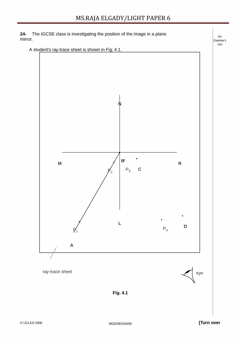
24- The IGCSE class is investigating the position of the image in a planemirror.
A student’s ray-trace sheet is shown in Fig. 4.1.
ForExaminer’s
Use
N
M B RP2
P3 C
LP P4
D
A
ray-trace sheet eye
Fig. 4.1

[Turn over© UCLES 2006 0625/06/O/N/06
MS.RAJA ELGADY/LIGHT PAPER 6

[Turn over© UCLES 2006 0625/06/O/N/06
MS.RAJA ELGADY/LIGHT PAPER 6The line MR shows the position of a plane mirror. NL is the normal at the centre of themirror.
AB marks the position of an incidentray.
The student pushes two pins, P1 and P2 into this line. She views the images of pins P1andP2 from the direction indicated by the eye in Fig.4.1.
She places two pins P3 and P4 some distance apart so that pins P4 and P3, and the imagesof P2 and of P1, all appear exactly one behind the other. The positions of P3 and P4 arelabelled.
(a) Draw in the line joining the positions of P3 and P4. Continue the line until it crossesMR
and extends at least 8.0cm beyond MR.[1]
(b) The student repeats the procedure without moving pin P1 but using a different angleof incidence. On Fig. 4.1, the new positions of pins P3 and P4 are marked C and D.
(i) Draw in the line joining the positions C and D. Continue the line until it extendsat least 8.0cm beyond MR.
(ii) Label with a Y the point where the two lines beyond MR cross.[1]
(c) (i) Draw a line from P1 to MR that meets MR at a right angle. Measure and recordthe length a of this line.
a = ......................................................
(ii) Draw a line from the point labelled Y to MR that meets MR at a right angle.Measure and record the length b of this line.
b =..................................
.
.
.
.
.
.
.
.
.
.
.
.
.
.
.
.
.
.
.
.
[2]

[Turn over© UCLES 2006 0625/06/O/N/06
MS.RAJA ELGADY/LIGHT PAPER 6(d) A student suggests that the length of a should equal the length ofb.
State whether your results support this suggestion. Justify your statement byreference to your results.
statement
.........................................................................................................................
justification
.......................................................................................................................
............................................................................................................................. ............
.
.......................................................................................................................................... [2]
(e) Suggest a precaution that you would take, when placing the pins, in order toobtain reliable results.
.........................................................................................................................................
.
............................................................................................................................. ......... [1] [Total: 7]

[Turn over© UCLES 2006 0625/06/O/N/06
MS.RAJA ELGADY/LIGHT PAPER 625- The IGCSE class is investigating the refraction of light passing through a transparentblock.
The apparatus and ray-trace sheet are shown in Fig. 4.1.
ForExaminer’s
Use
O
A B
D CP3
P4
ray-trace sheet eye
Fig. 4.1

[Turn over© UCLES 2006 0625/06/O/N/06
MS.RAJA ELGADY/LIGHT PAPER 6
r
r
r
(a) A student places the transparent block, largest face down, on the ray-trace sheet. Shedraws the outline of the block ABCD.
(i) On Fig. 4.1, draw a normal at the centre of side AB. Label the point E where thenormal crosses AB.
(ii) Draw a line FE to the left of the normal and at an angle of incidence i = 30° to thenormal. [2]
(b) The student places two pins P1 and P2 on the line FE, placing one pin close to E. Sheobserves the images of P1 and P2 through side CD of the block so that the images of P1and P2 appear one behind the other. She places two pins P3 and P4 between her eyeand the block so that P3 and P4, and the images of P1 and P2 seen through the block,appear one behind the other.
(i) On Fig. 4.1, mark suitable positions for the pins P1 and P2. [1]
(ii) Draw a line joining the positions of P3 and P4. Continue the line until it meets CDand label this point G.
ForExaminer’s
Use
(iii) Draw the line GE.[1]
(c) (i) Measure and record the angle of refraction r between the line GE and the normal.
(ii) Calculate the ratio i .
r = .................................................. [1]
ir = .................................................. [1]
(d) The student repeats the procedure but with the angle of incidence i = 40°. The angle ofrefraction r = 26°.
(i) Calculate the ratio i .
(ii) A student suggests that the ratio i
ir = .................................................. [1]
should be a constant.
State and explain briefly whether your results support this suggestion.
...................................................................................................................... ............
............................................................................................................................. .....
.............................................................................................................. ................ [1]
[Total: 8]

MS.RAJA ELGADY/LIGHT PAPER 6