Embed Size (px)
Citation preview

INTRODUCTION TO CAD
UNIT – I
MET71 COMPUTER AIDED DESIGN
Computer Aided Design (CAD) is assistance of computer in engineering processes such
as creation, optimization, analysis and modifications.
CAD involves creating computer models defined by geometrical parameters which can be
readily altered by changing relevant parameters. CAD systems enable designers to view objects
under a wide variety of representations and to test these objects by simulating real-world
conditions.
It is an integration of Mechanical and Computer technology to aid in the design process like
Modelling, Assembly, Drafting, Die Design, Tool Design, Sheet metal, analysis of products.
DESIGN PROCESS:
The process of designing something is characterized as an interactive procedure, which consists
of six identifiable steps or phases:
1. Recognition of need
2. Definition of problem
3. Synthesis
4. Analysis and optimization
5. Evaluation
6. Presentation
Recognition of need
Recognition of need involves the realization by someone that a problem exists for which
some corrective action should be taken
This might be the identification of some defect in a current machine design by an engineer
or the perception of a new product marketing opportunity by a salesperson
Definition of problem
Definition of the problem involves a thorough specification of the item to be designed
This specification includes physical and functional characteristics, cost, quality and
operating performance
Synthesis, Analysis and optimization
Synthesis and Analysis are closely related and highly iterative in the design process
A certain component or subsystem of the overall system is conceptualized by the
designer, subjected to analysis, improved through this analysis procedure and redesigned
This process is repeated until the design has been optimized within the constraints
imposed on the designer
The components and subsystems are synthesized into the final overall system in a similar
iterative manner
Evaluation and Presentation
M.SRINIVASSAN, ASST. PROF 1 RGCET

MET71 COMPUTER AIDED DESIGN
Evaluation is concerned with measuring the design against the specifications established
in the problem definition phase
This evaluation often requires the fabrication and testing of a prototype model to assess
operating performance, quality, reliability and other criteria
The final phase in the design process is the presentation of the design
This includes documentation of the design by means of drawings, material specifications,
assembly lists and so on
Essentially, the documentation requires that a design data base be created
Figure below illustrates the basic steps in the design process, indicating its iterative nature
The general design process by shiegly
Product Development and Manufacture:
Machines involved – Computers
Tasks – information processing
Use – assist in the definition and processing of information connected with design of products
M.SRINIVASSAN, ASST. PROF 2 RGCET

Process involved in bringing the product to Market
MET71 COMPUTER AIDED DESIGN
In recent years there have been several attempts to provide a formal description of these
stages or elements of the design process. Some variation in these descriptions, both in
terminology and in detail, but in general the agree that design progress in a step – by – step
manner from some statement of need through identification of the problem , a search for solution
and development of the chosen solution to manufacture, test and use. These descriptions of
design are often called models of the design process.
MORPHOLOGY OF DESIGN
To illustrate these we will consider two models which give different but complementary
insights into the process.
I. Steps of the design process according to Pahl and Beitz(1984)
II. The design process according to Ohsuga
M.SRINIVASSAN, ASST. PROF 3 RGCET

MET71 COMPUTER AIDED DESIGN
Steps of the design process according to Pahl and Beitz (1984)
In this model the design process is described by a flow diagram comprising four main phases
which may be summarized as:
M.SRINIVASSAN, ASST. PROF 4 RGCET

MET71 COMPUTER AIDED DESIGN
Although it presents a straightforward sequence of stages through the process, in practice
the main phase are not always so clearly defined, and there is invariable feedback to previous
stages and often iteration between stages.
The design process according to Ohsuga
Ohsuga again describes design as a series of stages, in this case progressing from
requirements through conceptual design and preliminary design to detail design.
In this case however the various stages of design process are generalized into common
form in which models of design are developed through a process of analysis and
evaluation leading to modification and refinement of the model.
In the early stage the tentative solution is proposed by designer. In this stage the design
refined and evolution and modification repeated at a greater level of detail.
M.SRINIVASSAN, ASST. PROF 5 RGCET

Application of design models:
MET71 COMPUTER AIDED DESIGN
Application of design model is to the receiver of the communication and considers the sort
of actions that are taken with the design information that is received.
This may be divided into two main classification
i. Evaluating actions
ii. Generative actions
In each case the actions involve the extraction of information from the design
representation and the combination of this with further information to form a new model.
This is shown diagrammatically in figure.
A design analyst might use this for the following assessments:
o A visual assessment
o An assessment of the mass of the components, by using the CAD model
o An evaluation of loads in the components, by considering them as parts of a
mechanism
o An evaluation of stresses, for example using the finite element model.
At the later stage, detailed drawings will exist of the components of the design, and from
these, manufacturing engineers will extract information for tooling and for the control of
production machines.
Types of Design Models:
The design process model gives as hint of variety of representation needed in design.
There are phrases such as ‘develop preliminary layouts’ and complete detail drawings’.
In practice, the designer uses a host of different models depending on what property of
the design is to be modeled, and who or what is the target, or receiver, for any
communication.
The engineering designer has, at various times, to modeled the function of a design, its
structure, the form or shape of the components parts and the materials, surface
conditions and dimensions that are required.
He or she may also wish to form mathematical models, or computer based
representations, to assist in the evolution of design.
The potential targets for communication include, among others, fellow designers,
manufacturing and workshop staff, and user of the design.
For any particular combination of modeled property and receiver there will be type of
model and technique for its generation that will be most appropriate.
Of all the modeled properties, form and structure are of particular importance in
engineering, and the most appropriate method of representing these has traditionally
been graphical.
For many engineers a major part of their task is to define the shape and arrangement of
the component parts of the design. This is conventionally achieved by drawings of form.
M.SRINIVASSAN, ASST. PROF 6 RGCET

MET71 COMPUTER AIDED DESIGN
Other engineers are more concentrated with the structure of the assembly of standard
elements to form a design, with the way these elements are connected together, and with
the flows between parts are often called a system engineering approach.
In the early stages of a design, the designer will often explore ideas by sketching, with
little or no detail. When information is being generated for manufacture, however, a more
diligent technique is required, and drawings and diagrams will be carefully produced to
show all necessary detail.
For any communication to be successful that must be understood by all those involved.
CONCURRENT ENGINEERING:
Concurrent engineering or Simultaneous Engineering is a methodology of restructuring
the product development activity in a manufacturing organization using a cross functional team
approach and is a technique adopted to improve the efficiency of product design and reduce the
product development cycle time.
This is also sometimes referred to as Parallel Engineering. Concurrent Engineering brings
together a wide spectrum of people from several functional areas in the design and manufacture
of a product. Representatives from R & D, engineering, manufacturing, materials management,
quality assurance, marketing etc. develop the product as a team.
Everyone interacts with each other from the start, and they perform their tasks in parallel.
The team reviews the design from the point of view of marketing, process, tool design and
procurement, operation, facility and capacity planning, design for manufacturability, assembly,
testing and maintenance, standardization, procurement of components and sub-assemblies,
quality assurance etc as the design is evolved.
Even the vendor development department is associated with the prototype development.
Any possible bottleneck in the development process is thoroughly studied and rectified. All the
departments get a chance to review the design and identify delays and difficulties.
The departments can start their own processes simultaneously. For example, the tool
design, procurement of material and machinery and recruitment and training of manpower which
contributes to considerable delay can be taken up simultaneously as the design development is
in progress. Issues are debated thoroughly and conflicts are resolved amicably.
Concurrent Engineering (CE) gives marketing and other groups the opportunity to review
the design during the modeling, prototyping and soft tooling phases of development. CAD
systems especially 3D modelers can play an important role in early product development phases.
In fact, they can become the core of the CE.
They offer a visual check when design changes cost the least. Intensive teamwork
between product development, production planning and manufacturing is essential for
satisfactory implementation of concurrent engineering.
The teamwork also brings additional advantages ; the co-operation between various
specialists and systematic application of special methods such as QFD (Quality Function
Deployment), DFMA (Design for Manufacture and Assembly) and FMEA (Failure Mode and
M.SRINIVASSAN, ASST. PROF 7 RGCET

MET71 COMPUTER AIDED DESIGN
Effect Analysis) ensures quick optimization of design and early detection of possible faults in
product and production planning. This additionally leads to reduction in lead time which reduces
cost of production and guarantees better quality.
Comparison of Concurrent Engineering and Sequential Engineering
A comparison of concurrent and sequential engineering based on cost is attempted in this
section. The distribution of the product development cost during the product development cycle is
shown in Fig. This figure shows that though only about 15% of the budget is spent at the time of
design completion, whereas the remaining 85% is already committed.
The decisions taken during the design stage have an important bearing on the cost of the
development of the product. Therefore the development cost and product cost can be reduced by
proper and careful design. CE facilitates this. The significantly large number of nonconformities
detected in the later stages of product development cycle in sequential engineering results in
large time and cost overrun.
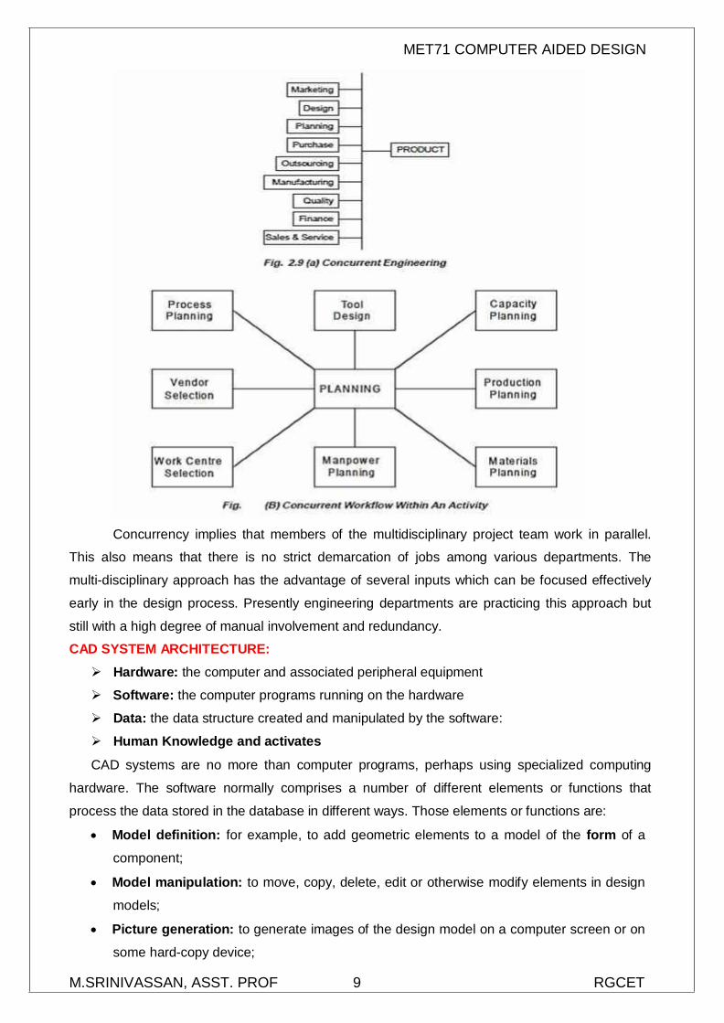
IMPLEMENTATION OF CONCURRENT ENGINEERING
The cycle of engineering design and manufacturing planning involves interrelated
activities in different engineering disciplines simultaneously, than sequentially as shown in Fig.
(A). In addition, the activities necessary to complete a particular task within a specific engineering
discipline have to emerge wherever possible from their sequential flow into a concurrent workflow
with a high degree of parallelism as illustrated in Fig. (B).
M.SRINIVASSAN, ASST. PROF 8 RGCET
MET71 COMPUTER AIDED DESIGN
Concurrency implies that members of the multidisciplinary project team work in parallel.
This also means that there is no strict demarcation of jobs among various departments. The
multi-disciplinary approach has the advantage of several inputs which can be focused effectively
early in the design process. Presently engineering departments are practicing this approach but
still with a high degree of manual involvement and redundancy.
CAD SYSTEM ARCHITECTURE:
Hardware: the computer and associated peripheral equipment
Software: the computer programs running on the hardware
Data: the data structure created and manipulated by the software:
Human Knowledge and activates
CAD systems are no more than computer programs, perhaps using specialized computing
hardware. The software normally comprises a number of different elements or functions that
process the data stored in the database in different ways. Those elements or functions are:
Model definition: for example, to add geometric elements to a model of the form of a
component;
Model manipulation: to move, copy, delete, edit or otherwise modify elements in design
models;
Picture generation: to generate images of the design model on a computer screen or on
some hard-copy device;
M.SRINIVASSAN, ASST. PROF 9 RGCET

MET71 COMPUTER AIDED DESIGN
User interaction: to handle commands input by user and to present output to the user
about the operation of the system;
Database management: for the management of the files that make up the database;
Application: these elements of the software do not modify the design model, but use it to
generate information for evaluation, analysis or manufacture;
Utilities: a ‘catch-all’ term for parts of the software that do not directly affect the design
model, but modify the operation of the system in some way (e.g to set the color to be used
for display, or the units to be used for construction of a part model).
These features may be provided by multiple programs operating on a common database or
by a single program encompassing all of these elements.
CAD Hardware
Workstation – CPU
Mass storage – Magnetic tape storage, Magnetic Disc Storage, Magnetic drum storage
Input devices - (keyboard, light pen, thumb wheel, joy stick, mouse, digitizer, Touch Screen,
Track Ball) Output devices - (printers, plotters)
Display Devices- (storage tube – raster scan, vector refresh, plasma panel and LCD)
Central Processing Unit:
The CPU is the Heart of the digital Computer, since it coordinates and controls the
activities of all other units. The CPU consists of three separate subsections;
1. Control Unit
2. Arithmetic Logic unit
3. Memory
M.SRINIVASSAN, ASST. PROF 10 RGCET

Control Unit:
MET71 COMPUTER AIDED DESIGN
The control unit is basically acts as an administrator in a computer. It coordinates the
operations of all other components. It controls the input and output of information between the
computer and the outside world through I/O devices, synchronizes the transfer of signals
between the various sections of the computer and regulates the other section to perform their
individual functions. The capability of the control unit to accomplish these operations is provided
by a set of instructions called executive program, which is stored in memory.
Arithmetic Logic unit
The ALU provides the circuitry required to perform the various calculations and
manipulations of data. Most ALU’s can add and subtract, but there are now some ALU’s that are
capable of performing multifunction and division and even other complex mathematical functions.
ALU’s with simplex circuits are capable of being programmed to perform these more complicated
operations, but more computing time is required. The more complex arithmetic logic units are
faster, but these units are more costly.
Memory
The memory section consists of binary storage units, which are organised into bytes. The
memory section stores all the instructions and data of a program. Therefore the CPU must
transfer these instructions and data. Two types of memory
Main memory (primary storage)
Auxiliary memory (Secondary storage)
Mass storage
The most common device used for computer storage technologies are
Magnetic tape storage
Magnetic Disc Storage
Magnetic drum storage
1) Magnetic tape storage
Magnetic storage is a good example of sequential access storage technology. Data are
stored on magnetic tape, similar to that used in audio systems. The major advantages of
magnetic tapes are that is relatively cheap when compared with other types of storage medium
and that it can easily hold large amount of data for its size. Magnetic tape unlike punched paper
tapes or cards can be used again by simply overwriting previously stored data.
Since data are stored sequentially access time is relatively slow. However, the low cost
per bit and high capacity of magnetic tape make it ideal for system backup. It is most suitable for
applications, which may be required in payroll, personnel management, inventory control and
customer invoicing where a large amount of data is to be processed sequentially.
2) Magnetic Disc Storage
Magnetic disk storage is also known as a random access storage device. The storage
medium is a magnetically coated disk. There are several types and sizes of disks each best
suited to a particular set of applications.
M.SRINIVASSAN, ASST. PROF 11 RGCET

3) Floppy Disc
MET71 COMPUTER AIDED DESIGN
Floppy disks come in two standard sizes: the larger one is 8 inches in diameter and
smaller is 5 ¼ inches and is referred to as mini floppy.
4) Magnetic Drum Storage
The magnetic drum is direct access storage device with high capacity and high access
rates. The magnetic drum consists of a magnetically coated cylinder during operation. The drum
is rotated at a constant speed and data are recorded in the form of magnetized spots. The drum
can be read repeatedly without causing data loss.
Input devices
Keyboard
Mouse
Light pen
Thumb wheel
Joy stick
Digitizer
Touch Screen
Track Ball
Keyboard
The keyboard interacts with the computer on a hardware and software level. The
keyboard contains a keyboard controller (like 8042 or 8048) to check if any key is pressed or
released. If any key remains closed for more than half a second the controller sends a repeat
action at specific intervals. It has limited diagnostic and error checking capabilities. A buffer is
normally available to store a certain number of key actions if the computer is busy.
Mouse
Mouse is today one of the widely used input devices in graphics applications. Mouse can
be moved around by the operator on any flat surface to provide graphic input. Its ability to rapidly
position the cursor on the screen is its most important advantage. Mouse is available as a
mechanical or optical graphic input device. In the case of a mechanical mouse, the rolling ball at
the bottoms of the mouse causes two encoders to rotate. The movement of the mouse is thus
converted into pulses which move the cursor in the X and Y direction in proportion to the
M.SRINIVASSAN, ASST. PROF 12 RGCET

MET71 COMPUTER AIDED DESIGN
movement of the mouse. Mouse can be operated in a limited space. Since the mouse can be
used without looking at it, the user can concentrate on the screen and hence design productivity
can be considerably increased.
Light pen
A light pen is a computer input device in the form of a light-sensitive wand used in
conjunction with a computer's CRT display.
It allows the user to point to displayed objects or draw on the screen in a similar way to a
touch screen but with greater positional accuracy. It was long thought that a light pen can
work with any CRT-based display, but not with LCDs and other display technologies. Thumb wheel
Thumb wheels are potentiometric devices. Two of them are provided for X and Y
movements of cursor. These also have the advantage that one can look at the screen and move
the cursor.
Joy stick
Joystick is a potentiometric device that contains sets of variable resistors which feed
signals that indicates the device position to the computer. These devices rely on the operator’s
sense of touch and hand-eye co-ordination to control the position of the cursor on the screen.
Joystick devices are normally set so that side-to-side movement produces change in X Co-
ordinates and front to back movements produce change in Y Co-ordinates.
M.SRINIVASSAN, ASST. PROF 13 RGCET

Digitizer
MET71 COMPUTER AIDED DESIGN
Digitizer boards or tablets are electro-mechanical vector graphic input devices that
resemble a drafting board. These are used together with a movable stylus or reticule called a
cursor or a puck. They are used to enter drawings into computer graphics systems by taping the
drawing to the surface of the digitizing board and placing the cursor over points whose co-
ordinates are to be entered. Figure shows a digitizer.
Touch Screen
Touch screens are direct devices. They are used by simply touching CRT display with
one’s finger or a pointing device. Two types of touch screens (mechanical and optical) are used
in CAD applications. Mechanical type is a transparent screen overlay which detects the location
of the touch.
Track Ball
Track ball has a ball and socket construction but the ball must be rolled with fingers or the
palm of the hand. The cursor moves in the direction of the roll at a rate corresponding to
rotational speed. The user must rely heavily on the tactile sense when using a trackball since
there is no correspondence between the position of the cursor and the ball. The ball momentum
provides a tactile feedback.
OUTPUT DEVICES
A CAD system is not complete unless it can make hard copies of designs or analysis
created on the computer. Determining the best output device for a typical CIM application is a
three-step process: specifying how hard copies will be used, identifying quality and cost criteria
and selecting equipment most suitable for the application. Hard copies are used for a variety of
purposes, including shop use, file storage, reports and presentations. Design iterations can be
reduced by making hard copies at crucial stages and distributing them to key personnel for
review. Documents and drawings are required for archival purposes, to be used in proposals,
M.SRINIVASSAN, ASST. PROF 14 RGCET

MET71 COMPUTER AIDED DESIGN
reports, as well as illustrations. Quality of the hard copy depends on the resolution of the hard
copy unit. Speed and frequency of operation of hard copy equipment are also of importance.
Printers
Plotters
PLOTTERS
Plotters are classified based several factors. Depending on the maximum size of the
drawing plotters are designated as A0, A1, A2, A3 and A4. There are plotters capable of creating
drawings larger than A0 size. Generally plotters plot drawings on cut sheets. Some special
plotters are capable of creating drawings on rolls also. Drawings are created through a series of
short vectors which requires movement to the pen in X and Y direction. Plotters can be classified
on the basis of their construction. A flat bed plotter has the pen moving on a flat surface on which
the drawing paper is fixed. The linear movements in the X and Y direction generate the required
drawing. In the case of a drum plotter, the paper is wound around on a cylindrical drum. The pen
holder is attached to a moving slide.
The co-ordinate motion generated by the rotation of the drum and linear movement draws
the pictures on the paper. In the third type, i.e. the pinch roller plotter, the paper is tightly held
between two sets of rollers. One roller in each pair has a rough surface and the linear motion to
the paper in one direction is imparted by the rotation of the roller. The movement in the other
direction is through a linear motion imparted to the pen holder. Plotters can also classify as pen
plotters and electrostatic plotters. Pen plotters use 1, 4, 8 or more different color pens. The
drawings thus can be made in several colors. Pencil plotters are also available. Electrostatic
plotters are faster but there is no color variety. They are also cheaper.
PRINTERS
Several types of printers are available:
(i) Impact printers: They use small hammers or print heads containing small pins to strike a
ribbon to form dot matrix images. Colors are introduced through the use of multiple ribbons or
single ribbons with different color bands. Color intensity is fixed and creating shades is almost
impossible. Because of the low resolution, copy quality is poor. Impact printers are suitable for
high speed, low cost, high volume hard copies.
M.SRINIVASSAN, ASST. PROF 15 RGCET

MET71 COMPUTER AIDED DESIGN
(ii) Inkjet printer: Inkjet printers produce images by propelling fine droplets of ink on to the
medium to be printed. Droplets can be generated in continuous streams or pulses. Some of the
droplets get charged and are returned to the reservoir, while uncharged droplets attach to the
printing surface to form graphics. The laser jet printers are capable of giving good quality color
prints with shading at reasonable cost.
(iii) Laser printer: Laser printer is one of the most widely used output devices. This type
combines high speed with high resolution and the quality of output is very fine.
DISPLAY DEVICES:
The graphics display of a workstation is considered its most important component
because the quality of the displayed image influences the perception of generated design
on the CAD/CAM system.
In addition to viewing images, the graphics display enables the user to communicate with
the displayed image by adding, deleting, blanking, and moving graphics entities on the
display screen.
As a matter of fact, this communication process is what gives interactive graphics its
name to differentiate it from passive graphics, as in the case of a home television set,
that the user cannot change.
Variable display technologies are now available to the user to choose from. They are all
based on the concept of converting computer’s electrical signals, controlled by the
corresponding digital information, into visible images at high speed.
Technologies
Cathode Ray Tube(CRT)
Laser Display
Flat Panel Display or Plasma panel Display
1. In the first a laser beam instead of an electron beam is used to trace an image in a film.
2. In the second a liquid crystal display (LCD) and light emitting diodes (LEDs) are used to
generate images
3. The plasma display uses small neon bulbs arranged in a panel which provides a medium
resolution display.
Thus far, none of these display technologies has been able to displace the CRT as the dominant
graphics display device.
CATHODE RAYS TUBE:
The operation of CRT is based on the concept of energizing an electron beam that strikes
the phosphor coating at very high speed. The energy transfer from the electron to the phosphor
due to the impact causes it to illuminate and glow.
M.SRINIVASSAN, ASST. PROF 16 RGCET

MET71 COMPUTER AIDED DESIGN
The electrons are generated via the electron gun that contains the cathode and focused
into a beam via the focusing unit shown in figure. By controlling the beam direction and intensity
in a way related to the graphics information generated in the computer, meaningful and desired
graphics can be displayed on the screen.
The graphics display can be divided into two types based on the scan technology used to
control the electron beam.
Random Scan
Raster Scan
In Random scan graphics can be generated by drawing vectors or line segments on the screen
in a random order which is controlled by the user input and the software. The word “random”
indicates that the screen is not scanned in a particular order.
M.SRINIVASSAN, ASST. PROF 17 RGCET

MET71 COMPUTER AIDED DESIGN
Raster Scan system, the screen is scanned from top to bottom, left to right all the time to
generate graphics. This is similar to home television scan system, thus suggesting the name
digital scan.
The three existing CRT display that are based on these techniques are
i. Refresh display (calligraphic)
ii. Direct view storage tube
iii. Raster display
Refresh Display
The refresh buffer stores the display file or program, which contains points, lines,
characters and other attributes of picture to drawn. These commands are interpreted and
processed by the display processor.
The electron beam accordingly excites the phosphor, which glows for a short period. To
maintain a steady flicker – free image, the screen must be refreshed or redrawn at least 30 to 60
times per second, that is, at a rate of 30 to 60 Hz.
M.SRINIVASSAN, ASST. PROF 18 RGCET

MET71 COMPUTER AIDED DESIGN
Changes made to the display file by the software must be synchronized with the display
refresh cycle to prevent the display of an incomplete picture. If the software updates the file fast
enough, then it is possible to use the dynamic techniques such as animation to simulate
movements as well as developing responsive user interfaces.
The principal advantage to refresh displays is its high resolution (4096 x 4096) and thus
its generation of high quality pictures. However, the need to refresh the picture places a limit on
the number of vectors that can be displayed without flicker
In addition, being a binary display, the refresh display is able to generate only two level of
color intensity. In some displays, the intensity of the electron beam can vary to provide better
color capabilities.
Direct View Storage Tube (DVST):
Refresh display were very expensive in the 1960s due to the required refresh buffer
memory and fast display processor, and could only display a few hundred vectors on the screen
without flicker. At the end of 1960s the DVST was introduced by Tektronix as an alternative and
inexpensive solution.
The DVST eliminates refresh processors completely and consequently the refresh buffer
used with refreshes display.
M.SRINIVASSAN, ASST. PROF 19 RGCET

MET71 COMPUTER AIDED DESIGN
It also uses a special type of phosphor that has a long – lasting glowing effect. The
phosphor is embedded in a storage tube. In addition, the speed of the electron beam in the DVST
is slower than in the refresh display due to elimination of refresh cycle.
In the DVST the picture is stored as a charge in the phosphor mesh located behind the
screen’s surface. Therefore, complex pictures could be drawn without flicker at high resolution.
Once displayed, the picture remains on the screen until it is explicitly erased. This
is why the name “storage tube” was suggested.
In addition to the lack of selective erasure, the DVST cannot provide colors, animation
and use of light pen as an input device.
Raster Display:
The inability of the DVST to meet the increasing demands by various CAD/CAM
applications for colors, shaded images and animation motivated hardware designer to continue
searching for a solution.
During the late 1970s raster display based on the standard television technology began to
emerge as a viable alternative. The drop in memory price due to advances in solid states made
large enough refresh buffers available support high resolution display.
A typical resolution of raster display is 1280 x 1204 with a possibility to reach 4096 x 4096
as the DVST. Raster displays are very popular and nearly al recent display research and
development focus on them.
M.SRINIVASSAN, ASST. PROF 20 RGCET

MET71 COMPUTER AIDED DESIGN
In raster display, the display screen area is divided horizontally and vertically into matrix of small
elements called picture element or pixel. A pixel is a small addressable area on the screen. An N
x M resolution defines on a screen with N rows and M Columns. Each row defines a scan line. A
rasterization process is needed in order to display either a shaded area or graphics entities.
In this process the area or entities are converted into their corresponding pixels whose
intensity and color are controlled by the image processing system.
Working:
Images are displayed by converting geometric information into pixel values which then
converted into electron beam deflection through display processor and deflection system. If the
display is monochrome, the pixel value is used to control the intensity level or the gray level on
the screen. For color displays, the value is used to control the color mapping into a color map.
The creation of transfer format data from geometric information is known as scan
conversion or rasterization. A rasterizer that forms the mage-creation system is mainly a set of
scan conversion algorithms. Due to the universal need for these algorithms, the scan conversion
or rasterization process is implemented.
M.SRINIVASSAN, ASST. PROF 21 RGCET