Embed Size (px)
Citation preview

MULTITASKER™
MANUAL PART NUMBER: 400-0376-002
1-IN, 6-OUT CAT-5DISTRIBUTION AMPLIFIER CARD FOR
MULTITASKER™ ENCLOSURESUSER’S GUIDE
MT103-121

MULTITASKER™
400-0376-002 1
TABLE OF CONTENTS
Page
PRECAUTIONS / SAFETY WARNINGS ............... 2GENERAL..........................................................2INSTALLATION .................................................2CLEANING.........................................................2FCC / CE NOTICE..............................................2
ABOUT YOUR MT103-121....................................... 3
TECHNICAL SPECIFICATIONS ............................ 3
PRODUCT DESCRIPTION ..................................... 4
APPLICATION DIAGRAM ........................................ 5DIAGRAM 1: TYPICAL SETUP ..........................5DIAGRAM 2: INTERNAL VIEW ..........................6DIAGRAM 3: JUMPER SETTINGS.....................7
INSTALLING YOUR MT103-121............................ 8
OPERATION ............................................................... 8RS-232 CONTROL.............................................8DESCRIPTION OF COMMANDS .......................8SUMMARY OF COMMANDS ...........................15MENU MODE...................................................16
TROUBLESHOOTING GUIDE .............................. 18CARD IS NOT RECOGNIZED..........................18NO DISPLAY....................................................18
ALTINEX POLICIES ................................................ 19LIMITED WARRANTY/RETURN POLICIES.....19CONTACT INFORMATION..............................19
MULTITASKER™
400-0376-002 2
PRECAUTIONS / SAFETY WARNINGS 1Please read this manual carefully before using yourMT103-121. Keep this manual handy for future reference. These safety instructions are to ensure the long life of your MT103-121 and to prevent fire and shock hazard. Please read them carefully and heed all warnings.
1.1 GENERAL
• Qualified ALTINEX service personnel, or their authorized representatives must perform all service.
1.2 INSTALLATION
• To prevent fire or shock, do not expose this unit to rain or moisture. Do not place the MT103-121 in direct sunlight, near heaters or heat radiating appliances, or near any liquid. Exposure to direct sunlight, smoke, or steam can harm internal components.
• Handle the MT103-121 carefully. Dropping or jarring can damage the card.
• Do not pull the cables that are attached to theMT103-121.
• Insert the card carefully into the slots of the MultiTasker without bending any edges.
1.3 CLEANING
• Clean only the connector area with a dry cloth. Never use strong detergents or solvents, such as alcohol or thinner. Do not use a wet cloth or water to clean the card. Do not clean or touch any component or PCB.
1.4 FCC / CE NOTICE
• This device complies with Part 15 of the FCC Rules. Operation is subject to the following two conditions: (1) This device may not cause harmful interference, and (2) this device must accept any interference received, including interference that may cause undesired operation.
• This equipment has been tested and found to comply with the limits for a Class A digital device, pursuant to Part 15 of the FCC Rules. These limits are designed to provide reasonable protection against harmful interference when the equipment is operated in a commercial environment. This equipment generates, uses, and can radiate radio frequency energy and, if not installed and used in accordance with the instruction manual, may cause harmful interference to radio communications. Operation of this equipment in a residential area is likely to cause harmful interference in which case the user will be required to correct the interference at his own expense.
• Any changes or modifications to the unit not expressly approved by ALTINEX, Inc. could void the user’s authority to operate the equipment.

MULTITASKER™
400-0376-002 3
ABOUT YOUR MT103-121 2
MT103-1211-in 6-out CAT5 Distribution Amplifier
The MT103-121 is a CAT-5 audio/video distribution amplifier (DA). It is designed to be used with Altinex CAT-5 Transmitters and Receivers, including part numbers DA1930CT and DA1931CT.
The MT103-121 is a 1-in 6-out DA Card. There is one CAT5 input and there are six CAT5 outputs. This card enables the connection of a single CAT-5 transmitter to six CAT-5 receivers.
The MT103-121 also features Equalization adjustment. The equalization allows the user to adjust the signal when long cable lengths are involved. The Equalization circuitry is good for cable runs up to about 400 feet when high quality cabled is used. The total distance from source to transmitter to receiver to display is 700 feet at resolutions up to 1024x768. An on board switch allows the user to choose between hardware and software control of Video Equalization.
Another feature available is the Loop Output. This output allows the same input to the MT103-121 to be easily connected to another MT103-121 orsimilar device. Switch settings allow the user to select between Loop Output or no Loop Output.
TECHNICAL SPECIFICATIONS 3FEATURES/
DESCRIPTION MT103-121
InputsMain Input RJ-45 Female (1)OutputsMain Output RJ-45 Female (6)Loop Output RJ-45 Female (1)Compatibility VGA thru UXGA, Stereo AudioApprovals CE/FCC
Table 1. MT103-121 General
MECHANICAL MT103-121Enclosure Slots OneWeight 0.43lb (0.19kg)Shipping Weight 1 lb. (0.42kg)Connector Panel BlackT° Operating 10°C-40°CT° Maximum 50°CHumidity 90% non-condensingMTBF (calc.) 55,000 hrs
Table 2. MT103-121 Mechanical
ELECTRICAL MT103-121Input SignalsCAT-5/6 Twisted PairInput
Video/Sync/Audio SignalsAltinex Standard
Output SignalsCAT-5/6 Twisted Pair Output
Video/Sync/Audio Signals Altinex Standard
Power (Enclosure) +6V -6V Power
MT103-121 760mA 700mA 8.8watts
Table 3. MT103-121 Electrical

MULTITASKER™
400-0376-002 4
PRODUCT DESCRIPTION 4
TOP RETAINER SCREW
BOTTOM RETAINER SCREW
HARDWARE EQUALIZATION
6 OUTPUTS
INPUT
LOOP OUTPUT

MULTITASKER™
400-0376-002 5
APPLICATION DIAGRAM 5DIAGRAM 1: TYPICAL SETUP
MT103-121
MULTITASKER™
400-0376-002 6
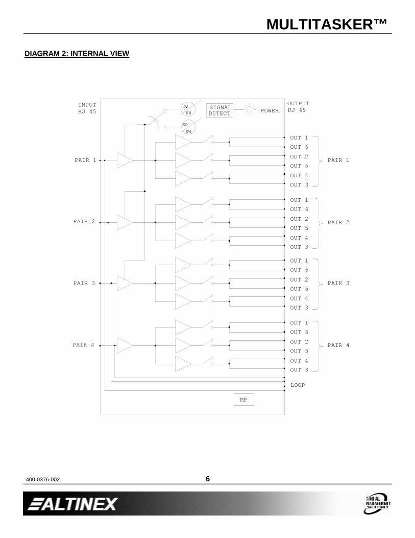
DIAGRAM 2: INTERNAL VIEW
HWEQ SIGNAL
DETECT
SWEQ
MP
POWER
OUT 3
LOOP
PAIR 3
PAIR 4
OUT 4
OUT 2OUT 6OUT 1
OUT 5
OUT 4OUT 5
OUT 3
OUT 2
PAIR 2
OUT 3
OUT 5OUT 4
OUT 1OUT 6
OUT 3
OUT 2OUT 6OUT 1
PAIR 1
OUT 1OUT 6
OUT 5OUT 2
OUT 4
PAIR 4
PAIR 3
PAIR 2
PAIR 1
INPUTRJ 45
OUTPUTRJ 45
MULTITASKER™
400-0376-002 7
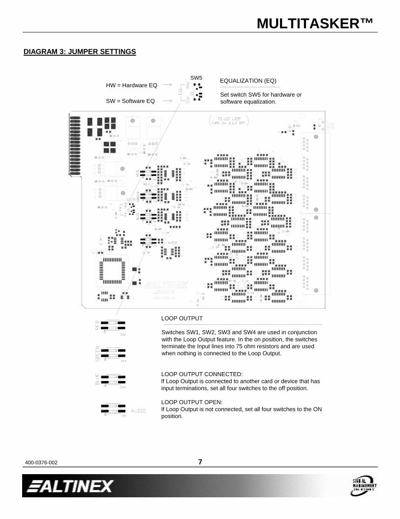
DIAGRAM 3: JUMPER SETTINGS
LOOP OUTPUT
Switches SW1, SW2, SW3 and SW4 are used in conjunction with the Loop Output feature. In the on position, the switches terminate the Input lines into 75 ohm resistors and are used when nothing is connected to the Loop Output.
LOOP OUTPUT CONNECTED:If Loop Output is connected to another card or device that has input terminations, set all four switches to the off position.
LOOP OUTPUT OPEN:If Loop Output is not connected, set all four switches to the ON position.
SW5 EQUALIZATION (EQ)
Set switch SW5 for hardware or software equalization.
HW = Hardware EQ
SW = Software EQ
MULTITASKER™
400-0376-002 8
INSTALLING YOUR MT103-121 6Step 1. Determine if the Loop Output will be
connected to another card input. If the Loop Output is going to be used, set switches SW1, SW2, SW3 and SW4 to the OFF position. See DIAGRAM 3 on page 7 for details.
Step 2. Determine if Video Equalization will be controlled through hardware or software. If software controlled, set switch SW5 to the SW position. See DIAGRAM 3 on page 7 for details.
Step 3. Turn off power to the MultiTasker system and disconnect from AC power.
Step 4. Slide the MT103-121 into an available slot in the MultiTasker enclosure in order to connect to the bus. Make sure that the card fits into place and secure the card to the MultiTasker by tightening the top and bottom retainer screws on the card.
Step 5. Restore power to the MultiTasker system.
Step 6. If the power is ON, the LED on the card will turn red indicating that the card is in full operation. If the LED does not come on, it may be necessary to reset the system or turn the system power off and then back on.
Step 7. Connect a CAT-5/6 cable from the CAT-5 Transmitter to the input connector of the MT103-121 card.
Step 8. Connect at least one of the output connectors to a CAT5 Receiver through a CAT-5/6 cable. The outputs are always on, so the display connected to the CAT-5 Receiver should have a display present.
Step 9. Starting from the left, identify the slot number the MT103-121 card is plugged into, and note that it is for RS-232 control.
OPERATION 77.1 RS-232 CONTROL When used in the MultiTasker Enclosure, the MT103-121 has many advanced remote control capabilities, which are accessible through standard RS-232 communication. The actual controlling can be accomplished through a computer control system or any other device capable of sending RS-232 commands.
7.1.1 RS-232 INTERFACE
The RS-232 commands, for the MT103-121, are in a simple ASCII character format.
1. Square brackets “[ ]” are part of the command.
2. Use uppercase letters for all commands.
After processing a command, an OK or ER will be returned as feedback if "F" is included at the end of a command string.
Commands ending in "S" will be saved into memory. Commands not ending in "S" will still be executed but will not be restored when the system is reset or powered OFF then ON.
7.2 DESCRIPTION OF COMMANDSEach command consists of three parts: Function, Card ID, and Unit ID.
[ Function , Card ID , Unit ID ]Example: [VERC3U2]
VER = FunctionC3 = Card ID or Group IDU2 = Unit ID
For Function, see a detailed explanation under each command description.
The Card ID is an assigned value. It is equal to the enclosure slot number in which the card is installed. The value can range from 1 to 4 up to 1 to 20 depending on the enclosure.
Card ID 0 (C0) is used for the controller. See the MT100-100 User’s Guide for details.

MULTITASKER™
400-0376-002 9
The Group ID is a number representing a group of cards defined with the [WR] command. When using the Group ID, all cards in the group will perform the given instruction.
Changing the position of a card will significantly affect the commands recorded on software definitions or third party control systems.
The Unit ID has a value from 0 to 9. Unit ID 0 should be used for single unit operation. If the Unit ID is set to zero, each command may be used without Ui. Use the command [SETU0], as explained in the MT100-100 User’s Guide.
Example:
[VERC3]: For Unit ID Zero[VERC3Ui]: For Unit ID other than Zero[VERC3]: Equivalent to [VERC3U0]
1. [VER]This command displays the software version and card type for the MT103-121 card.
Command Format: [VERCnUi]
Cn = Card ID (n = slot # from 1 to max slots)
Ui = Unit ID (i = # from 0 to 9)
Example:
An MT103-121 card is in slot #2. Send thecommand [VERC2], and the MultiTasker Enclosure will return the following feedback:
[MT103-121 690-0197-005C05]
MT103-121 = card type690-0197-005 = software versionC05 = card ID
2. [C]This command receives the status of the card.
Command Format: [CnUi]
Cn = Card ID (n = # from 1 to max slots)
Ui = Unit ID (i = from 0 to 9)
Example:
There is one MT103-121 card in slot #10. Sending the command [C10] to the MultiTasker will yield the following feedback:
ON, EQ=0 C10
ON = Outputs are ONEQ=0 = Equalization is set to zeroC10 = The card is in slot 10
If there is no card in slot #10, sending the command [C10] will not return any feedback.
3. [CnS]This command saves the card settings and displays the status. After the system is reset or powered off and then on, the card restores the saved settings.
Cn = card numberS = save configuration
Example:
Save the status by sending the command [C10S]. The feedback returned will be similar to the following:
ON, EQ=0 C10 [SAVED]
FEEDBACK COMMANDS ?, ?Cn and STAThe next four commands are a function of both the card and the front panel and are only available with MultiTasker Front Panel systems that have the following firmware:
690-0122-015 = Version 015 or later.690-0123-004 = Version 004 or later.690-0124-018 = Version 018 or later.
Send the command [VER], and the system will respond with feedback that includes the following:
690-0122-015 690-0123-004 690-0124-018
Check the last three digits against the numbers above to determine if the option is available.
4. [?]This command will return general information about the MultiTasker and cards installed in the unit.

MULTITASKER™
400-0376-002 10
Command Format: [?Ui]
Ui = Unit ID (i = from 0 to 9)
Example:
A MultiTasker with Unit ID #1 has a front panel with part number MT101-101 and contains an MT103-122, MT103-123 and MT106-103. Send the command [?U1] and receive the following feedback:
[(MT101-101U1)(MT103-121C01) (MT103-122C02)(MT103-123C03)]
MT101-101U1 = Panel Number and Unit IDMT103-121C01 = An MT103-122 is in slot 1MT103-122C02 = An MT103-122 is in slot 2MT103-123C03 = An MT103-123 is in slot 3
5. [?C]This command will return general information about the card and its status.
Command Format: [?CnUi]
Cn = Card ID (n = # from 1 to max slots)Ui = Unit ID (i = from 0 to 9)
Example:
The MT103-121 is in slot #4. Send the command [?C4] to receive feedback statussimilar to the following.
[(MT103-121C05)(VR690-0197-005C05)(ONC05)(EQ0C05)(SI0C05)]
All status feedback is enclosed in brackets, “[ ]“. Each data field within the status is enclosed in parentheses. The first two characters identify the status type. The last three characters are the card’s ID.MT103-121 = Card Model NumberVR690-0197-005 = Firmware versionON = Output ONEQ0 = Equalization is zeroSI0 = Input Signal Detect
The EQ (video equalization) setting is a value from 0 to 50.
The SI (input signal detect) will be a ‘0’ of no signal is present and a ‘1’ if a valid signal is present.
6. [STA1]This command enables automatic feedback from the front panel. The command affects any card with auto-feedback capability, not just the MT103-121 The default at power on or reset is STA0, off. For more details, see the [?Cn] command definition.
Command Format [STA1] = On
Feedback Prefix Definitions:MT Card Model NumberVR Firmware RevisionON Output On/Off StatusEQ Video EqualizationSI Input Signal Detect
Example:
Command = [EQ=10C4]Feedback = (EQ10C04)
EQ = Video Equalization10 out of 50
C04 = Card ID7. [STA0]
This command disables automatic feedback from the card and front panel. The command affects any card with auto-feedback capability, not just the MT103-121 The default at power on or reset is STA0, OFF.
Command Format [STA0]
8. [SIG]This command will test for the presence of an input signal and return a '1' if a signal is present and return a '0' if no signal is present.
Command Format: [SIGCnUi]
Cn = Card ID (n = # from 1 to max slots)
Ui = Unit ID (i = from 0 to 9)
MULTITASKER™
400-0376-002 11
Example:
If there is an MT103-121 in slot #10 and there is a valid CAT5 signal present on the input, sending the command [SIGC10] will yield the following feedback:
1
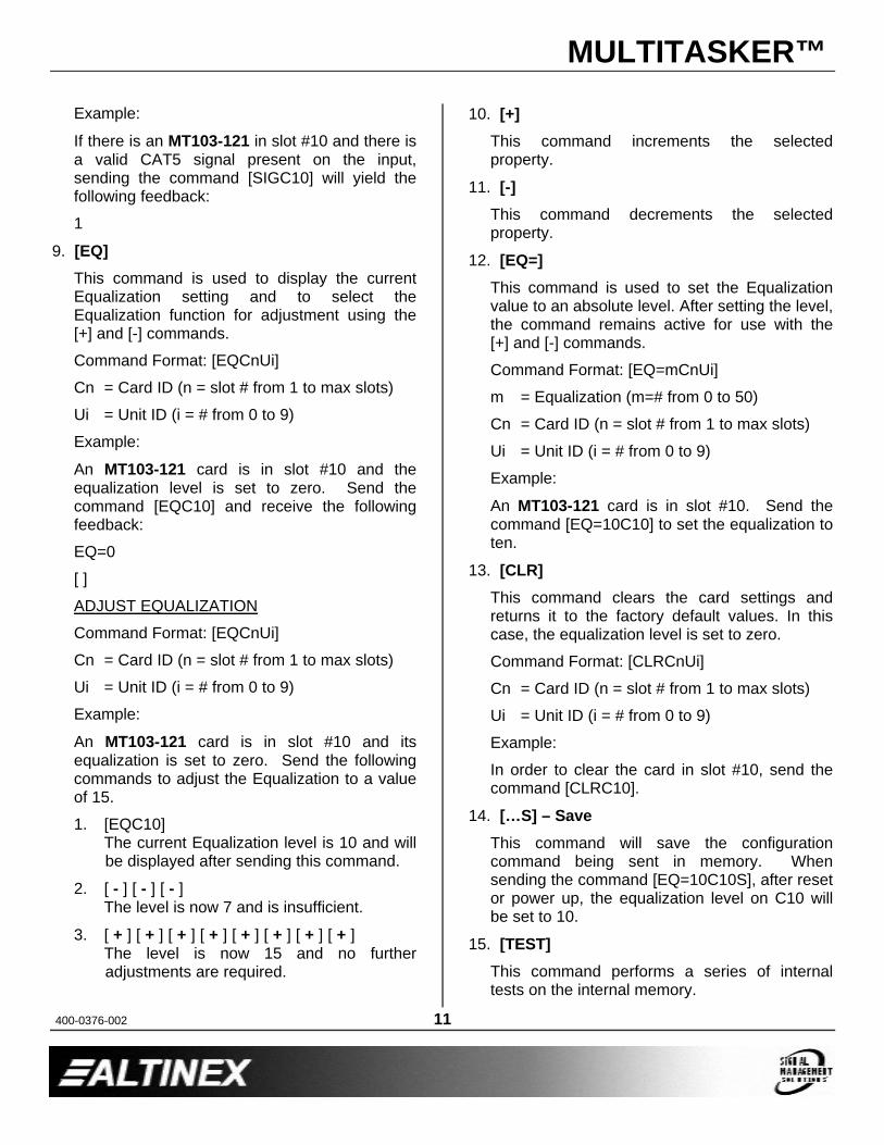
9. [EQ]This command is used to display the current Equalization setting and to select the Equalization function for adjustment using the [+] and [-] commands.
Command Format: [EQCnUi]
Cn = Card ID (n = slot # from 1 to max slots)
Ui = Unit ID (i = # from 0 to 9)
Example:
An MT103-121 card is in slot #10 and the equalization level is set to zero. Send the command [EQC10] and receive the following feedback:
EQ=0
[ ]
ADJUST EQUALIZATION
Command Format: [EQCnUi]
Cn = Card ID (n = slot # from 1 to max slots)
Ui = Unit ID (i = # from 0 to 9)
Example:
An MT103-121 card is in slot #10 and its equalization is set to zero. Send the following commands to adjust the Equalization to a value of 15.
1. [EQC10]The current Equalization level is 10 and will be displayed after sending this command.
2. [ - ] [ - ] [ - ]The level is now 7 and is insufficient.
3. [ + ] [ + ] [ + ] [ + ] [ + ] [ + ] [ + ] [ + ]The level is now 15 and no further adjustments are required.
10. [+]This command increments the selected property.
11. [-]This command decrements the selected property.
12. [EQ=]This command is used to set the Equalization value to an absolute level. After setting the level, the command remains active for use with the [+] and [-] commands.
Command Format: [EQ=mCnUi]
m = Equalization (m=# from 0 to 50)
Cn = Card ID (n = slot # from 1 to max slots)
Ui = Unit ID (i = # from 0 to 9)
Example:
An MT103-121 card is in slot #10. Send the command [EQ=10C10] to set the equalization to ten.
13. [CLR]This command clears the card settings and returns it to the factory default values. In this case, the equalization level is set to zero.
Command Format: [CLRCnUi]
Cn = Card ID (n = slot # from 1 to max slots)
Ui = Unit ID (i = # from 0 to 9)
Example:
In order to clear the card in slot #10, send the command [CLRC10].
14. […S] – SaveThis command will save the configuration command being sent in memory. When sending the command [EQ=10C10S], after reset or power up, the equalization level on C10 will be set to 10.
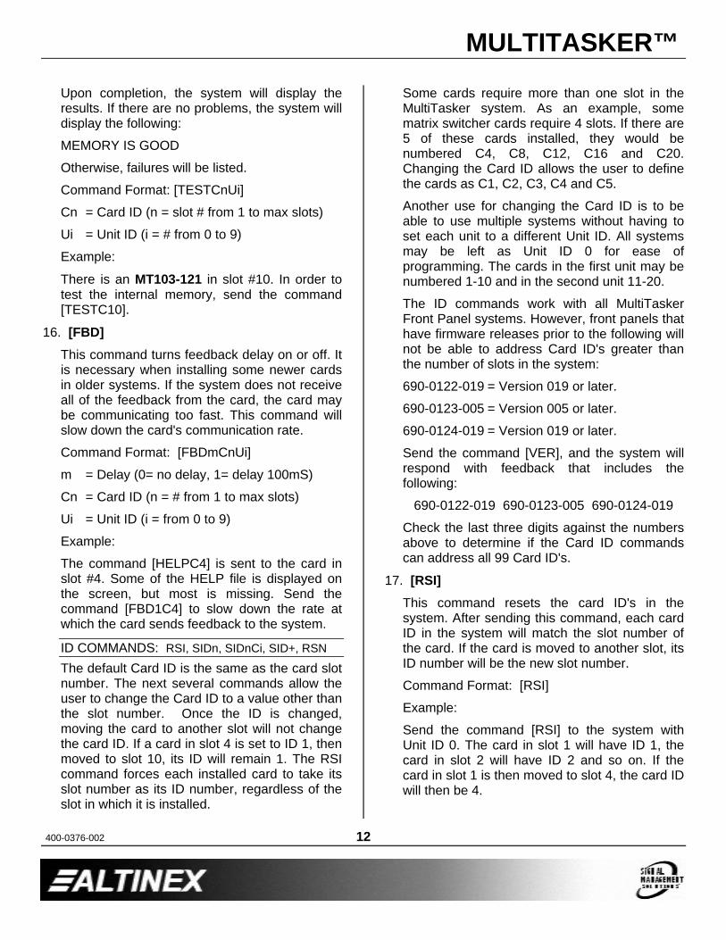
15. [TEST]This command performs a series of internal tests on the internal memory.
MULTITASKER™
400-0376-002 12
Upon completion, the system will display the results. If there are no problems, the system will display the following:
MEMORY IS GOOD
Otherwise, failures will be listed.
Command Format: [TESTCnUi]
Cn = Card ID (n = slot # from 1 to max slots)
Ui = Unit ID (i = # from 0 to 9)
Example:
There is an MT103-121 in slot #10. In order to test the internal memory, send the command [TESTC10].
16. [FBD]This command turns feedback delay on or off. It is necessary when installing some newer cards in older systems. If the system does not receive all of the feedback from the card, the card may be communicating too fast. This command will slow down the card's communication rate.
Command Format: [FBDmCnUi]
m = Delay (0= no delay, 1= delay 100mS)
Cn = Card ID (n = # from 1 to max slots)
Ui = Unit ID (i = from 0 to 9)
Example:
The command [HELPC4] is sent to the card in slot #4. Some of the HELP file is displayed on the screen, but most is missing. Send the command [FBD1C4] to slow down the rate at which the card sends feedback to the system.
ID COMMANDS: RSI, SIDn, SIDnCi, SID+, RSN
The default Card ID is the same as the card slot number. The next several commands allow the user to change the Card ID to a value other than the slot number. Once the ID is changed, moving the card to another slot will not change the card ID. If a card in slot 4 is set to ID 1, then moved to slot 10, its ID will remain 1. The RSI command forces each installed card to take its slot number as its ID number, regardless of the slot in which it is installed.
Some cards require more than one slot in the MultiTasker system. As an example, some matrix switcher cards require 4 slots. If there are 5 of these cards installed, they would be numbered C4, C8, C12, C16 and C20. Changing the Card ID allows the user to define the cards as C1, C2, C3, C4 and C5.
Another use for changing the Card ID is to be able to use multiple systems without having to set each unit to a different Unit ID. All systems may be left as Unit ID 0 for ease of programming. The cards in the first unit may be numbered 1-10 and in the second unit 11-20.
The ID commands work with all MultiTasker Front Panel systems. However, front panels that have firmware releases prior to the following will not be able to address Card ID's greater than the number of slots in the system:
690-0122-019 = Version 019 or later.
690-0123-005 = Version 005 or later.
690-0124-019 = Version 019 or later.
Send the command [VER], and the system will respond with feedback that includes the following:
690-0122-019 690-0123-005 690-0124-019
Check the last three digits against the numbers above to determine if the Card ID commands can address all 99 Card ID's.
17. [RSI]This command resets the card ID's in the system. After sending this command, each card ID in the system will match the slot number ofthe card. If the card is moved to another slot, its ID number will be the new slot number.
Command Format: [RSI]
Example:
Send the command [RSI] to the system with Unit ID 0. The card in slot 1 will have ID 1, the card in slot 2 will have ID 2 and so on. If the card in slot 1 is then moved to slot 4, the card ID will then be 4.
MULTITASKER™
400-0376-002 13
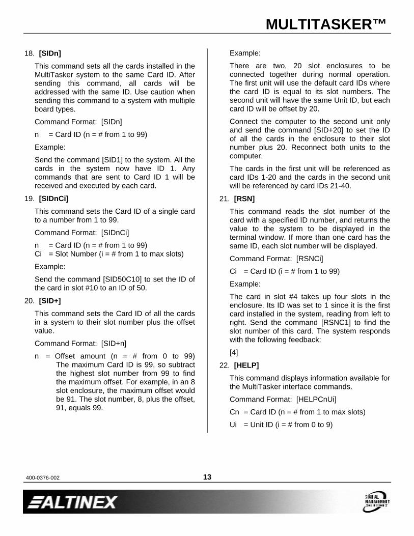
18. [SIDn]This command sets all the cards installed in the MultiTasker system to the same Card ID. After sending this command, all cards will be addressed with the same ID. Use caution when sending this command to a system with multiple board types.
Command Format: [SIDn]
n = Card ID (n = # from 1 to 99)
Example:
Send the command [SID1] to the system. All the cards in the system now have ID 1. Any commands that are sent to Card ID 1 will be received and executed by each card.
19. [SIDnCi]This command sets the Card ID of a single card to a number from 1 to 99.
Command Format: [SIDnCi]
n = Card ID (n = # from 1 to 99)Ci = Slot Number (i = # from 1 to max slots)
Example:
Send the command [SID50C10] to set the ID of the card in slot #10 to an ID of 50.
20. [SID+]This command sets the Card ID of all the cards in a system to their slot number plus the offset value.
Command Format: [SID+n]
n = Offset amount (n = # from 0 to 99)The maximum Card ID is 99, so subtract the highest slot number from 99 to find the maximum offset. For example, in an 8 slot enclosure, the maximum offset would be 91. The slot number, 8, plus the offset, 91, equals 99.
Example:
There are two, 20 slot enclosures to be connected together during normal operation. The first unit will use the default card IDs where the card ID is equal to its slot numbers. The second unit will have the same Unit ID, but each card ID will be offset by 20.
Connect the computer to the second unit only and send the command [SID+20] to set the ID of all the cards in the enclosure to their slot number plus 20. Reconnect both units to the computer.
The cards in the first unit will be referenced as card IDs 1-20 and the cards in the second unit will be referenced by card IDs 21-40.
21. [RSN]This command reads the slot number of the card with a specified ID number, and returns the value to the system to be displayed in the terminal window. If more than one card has the same ID, each slot number will be displayed.
Command Format: [RSNCi]
Ci = Card ID (i = # from 1 to 99)
Example:
The card in slot #4 takes up four slots in the enclosure. Its ID was set to 1 since it is the first card installed in the system, reading from left to right. Send the command [RSNC1] to find the slot number of this card. The system responds with the following feedback:
[4]
22. [HELP]This command displays information available for the MultiTasker interface commands.
Command Format: [HELPCnUi]
Cn = Card ID (n = # from 1 to max slots)
Ui = Unit ID (i = # from 0 to 9)

MULTITASKER™
400-0376-002 14
Example:
In order to display the RS-232 commands available for the MT103-121 card in slot #10, send the command [HELPC10]. The commands along with a brief description will be displayed in the Terminal Window.
GROUP COMMANDS
The next few commands are group commands. The use of groups allows several boards, with the same functions, to be controlled simultaneouslywith a single command. These commands apply to all cards in gereral and are provided for information purposes.
23. [WR]This command groups multiple cards in the enclosure allowing all the group members to be controlled simultaneously with the same command. Each MultiTasker unit may define a maximum of eight groups.
In MultiTasker systems with audio and video cards, boards are typically grouped as follows:
Group 1 = Video CardsGroup 2 = Audio CardsGroup 3 = Video and Audio Cards
Command Format: [WRCn1Cn2…GkUi]
Cn = Card ID (n = slot # from 1 to max slots)Gk = Group number (k = # from 1-8)Ui = Unit ID (i = # from 0-9)
Example:
Group cards 2, 4, and 6 as group 5 of Unit ID 1by sending the command [WRC2C4C6G5U1]. After executing this command, cards 2, 4 and 6will be grouped together as group 5 of Unit ID 1. The system will return the following feedback:
[G5=C2C4C6]
Now, when a command is sent to G5, each board in G5 will execute the same command.
24. [RMC]This command may be used to remove one or more group members from a group. Reset the system after using this command for all changes to take effect.
Command Format: [RMCn1Cn2…GkUi]
Cn = Card ID (n= # from 1 to max slots)Gk = Group ID (k = # from 1-8)Ui = Unit ID (i = # from 0-9)
Example:
Group 5 consists of the cards located in slots numbered 2, 4, and 6. Remove just cards 4 and 6 from the group by sending the command [RMC4C6G1]. The system will return the following feedback:
[G5=C2]
25. [RMG]This command may be used to delete an entire group, or all groups.
REMOVE A GROUP
Remove all the members from the group, effectively deleting the group.
Command Format: [RMGkUi]
Gk = Group ID (k = # from 1-8)
Ui = Unit ID (i = # from 0-9)
Example:
Group 5 consists of the cards located in slots number 2, 4 and 6. Remove all cards from the group by sending the command [RMG5]. The system will return the following feedback:
[G5=0]
REMOVE ALL GROUPS
Remove all the members from every group, effectively deleting all groups.
Command Format: [RMG*Ui]
Ui = Unit ID (i = # from 0-9)
MULTITASKER™
400-0376-002 15
Example:
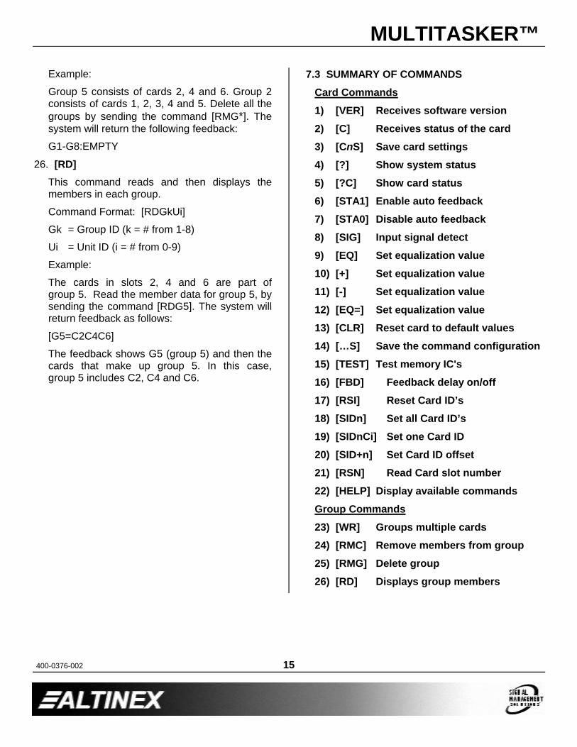
Group 5 consists of cards 2, 4 and 6. Group 2 consists of cards 1, 2, 3, 4 and 5. Delete all the groups by sending the command [RMG*]. The system will return the following feedback:
G1-G8:EMPTY
26. [RD]This command reads and then displays the members in each group.
Command Format: [RDGkUi]
Gk = Group ID (k = # from 1-8)
Ui = Unit ID (i = # from 0-9)
Example:
The cards in slots 2, 4 and 6 are part of group 5. Read the member data for group 5, by sending the command [RDG5]. The system will return feedback as follows:
[G5=C2C4C6]
The feedback shows G5 (group 5) and then the cards that make up group 5. In this case,group 5 includes C2, C4 and C6.
7.3 SUMMARY OF COMMANDS
Card Commands
1) [VER] Receives software version
2) [C] Receives status of the card
3) [CnS] Save card settings
4) [?] Show system status
5) [?C] Show card status
6) [STA1] Enable auto feedback
7) [STA0] Disable auto feedback
8) [SIG] Input signal detect
9) [EQ] Set equalization value
10) [+] Set equalization value
11) [-] Set equalization value
12) [EQ=] Set equalization value
13) [CLR] Reset card to default values
14) […S] Save the command configuration
15) [TEST] Test memory IC's
16) [FBD] Feedback delay on/off
17) [RSI] Reset Card ID’s
18) [SIDn] Set all Card ID’s
19) [SIDnCi] Set one Card ID
20) [SID+n] Set Card ID offset
21) [RSN] Read Card slot number
22) [HELP] Display available commands
Group Commands
23) [WR] Groups multiple cards
24) [RMC] Remove members from group
25) [RMG] Delete group
26) [RD] Displays group members
MULTITASKER™
400-0376-002 16
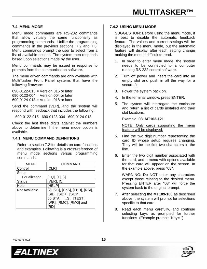
7.4 MENU MODEMenu mode commands are RS-232 commands that allow virtually the same functionality as programming commands. Unlike the programming commands in the previous sections, 7.2 and 7.3, Menu commands prompt the user to select from a list of available options. The system then responds based upon selections made by the user.
Menu commands may be issued in response to prompts from the communication software.
The menu driven commands are only available with MultiTasker Front Panel systems that have the following firmware:
690-0122-015 = Version 015 or later.690-0123-004 = Version 004 or later.690-0124-018 = Version 018 or later.
Send the command [VER], and the system will respond with feedback that includes the following:
690-0122-015 690-0123-004 690-0124-018
Check the last three digits against the numbers above to determine if the menu mode option is available.
7.4.1 MENU COMMAND DEFINITIONSRefer to section 7.2 for details on card functions and examples. Following is a cross-reference of menu mode sections versus programming commands.
MENU COMMANDControl [CLR]Setup
Equalization [EQ], [+], [-]Status [VER], [C]Help [HELP]Not Available [?], [?C], [CnS], [FBD], [RSI],
[SID], [SID+], [SIDn], 55[STA], […S], [TEST], [WR], [RMC], [RMG] and [RD]
7.4.2 USING MENU MODESUGGESTION: Before using the menu mode, it is best to disable the automatic feedback feature. The values and current settings will be displayed in the menu mode, but the automatic feature will display after each setting change making the menus difficult to read.
1. In order to enter menu mode, the system needs to be connected to a computer running RS-232 control software.
2. Turn off power and insert the card into an empty slot and push in all the way for a secure fit.
3. Power the system back on.
4. In the terminal window, press ENTER.
5. The system will interrogate the enclosure and return a list of cards installed and their slot locations.
Example: 08: MT103-121NOTE: Only cards supporting the menu feature will be displayed.
5. Find the two digit number representing the card ID whose setup requires changing. They will be the first two characters in the line.
6. Enter the two digit number associated with the card, and a menu with options available for that card will appear on the screen. In the example above, press "08".
WARNING: Do NOT enter any characters except those relating to the desired menu. Pressing ENTER after "08" will force the system back to the original prompt.
7. After selecting the MT109-100 as described above, the system will prompt for selections specific to that card.
8. Read each menu carefully, and continue selecting keys as prompted for further functions. (Example prompt: "Key= ")

MULTITASKER™
400-0376-002 17
7.4.3 MENU TYPES1. MAIN MENU
The first menu displayed after selecting the card is the Main Menu. This menu provides access to the main functions related to the card. Press the key representing the menu item for access. A sub menu appears next.
2. SUB MENUS
Each sub menu will display either another menu (sub menu) or a list of available options or settings. Press the key corresponding to the menu choice to change a setting or select the next menu.
NOTE: Pressing the ESCAPE (ESC) key in most menus will take you up to the previous menu without making changes in the current menu. In the some menus, the ESC key is used to confirm a setting change and return to the previous menu.
7.4.4 MT103-121 MENUSFollowing are the menus available to the MT103-121. The first menu is the Main Menu only. The second listing is an expansion of all the menu items available.
The expanded menu contains values in parentheses indicating the current setting or value of the parameter. In some areas, additional comments are provided for clarification.
MT103-121 MAIN MENU1: CONTROL2: SETUP3: STATUS4: HELPESC: GO BACK
MT103-121 EXPANDED MENUS1. CONTROL:
1: CLEAR (Set to defaults)1: YES2: NO
ESC: GO BACK
2. SETUP:1: SET EQUALIZATION
SET EQUALIZATION: (EQ=3)1: INCREASE EQ2: DECREASE EQ
ESC: GO BACK3: STATUS
Equivalent to the [C] command.Returns the card status and redisplays the Main Menu.
4: HELPEquivalent to the [HELP] command.Displays a list of commands available for the MT103-121 along with a brief description.
ESCReturns to the parent menu.
7.4.5 MENU MODE EXAMPLESAll MENU MODE examples assume an MT103-121 is installed in slot #1. Start by clicking the mouse in the Terminal window. Press ENTER and a list of available cards will be displayed.
NOTE When entering numeric values (not selecting menu items) the system may echo each character as it is typed. For example, entering a delay time of 03 may appear as 0033 on the screen.
1. Increase the equalization.Follow the keystrokes below to increase the level of equalization.
Enter List available cards01 Select MT103-121 in slot #12 Select SETUP Menu1 Select SET EQUALIZATION1 INCREASE EQUALIZATION
Repeat until desired equalization levelis obtained.
ESC Return to SETUP MenuESC Return to the MAIN Menu

MULTITASKER™
400-0376-002 18
2. Clear the card.Starting from the Main Menu, select the MT103-121 card and set it to the factory defaults. Follow the keystrokes below.
1 Select CONTROL Menu1 Select CLEAR1 Select YES to clear the cardESC Return to the MAIN Menu
3. Display Card StatusStarting from the Main Menu, follow the keystrokes below.
3 Displays card status
NOTE: The status will be displayed, followed by the Main Menu being redisplayed.
TROUBLESHOOTING GUIDE 8We have carefully tested and have found no problems in the supplied MT103-121. However, we would like to offer suggestions for the following:
8.1 CARD IS NOT RECOGNIZED
Cause 1: The card is not recognized.Solution: Reset the card cage by sending the
[RES] command, or turning the system power off and then on again. Send the [C] command to see if there is communication with the card. If there is no feedback, see Cause 2.
Cause 2: Card is not plugged in all the way.Solution: Push the card in all the way. Reset
the system and send the [C] command. If the card is still not recognized, see Cause 3.
Cause 3: Card cage slot has a problem.Solution 1: Test the card in other slots of the
card cage. If the slot was damaged, the card may work in other slots. If other slots work and the card is recognized, the problem is the card cage slot. The card cage may require service. Call ALTINEX at (714) 990-2300. If the other slots do not work, see Solution 2.
Solution 2: Take any other known good card and verify that the slot used is good by seeing if the other car is recognized in that slot. If it is, then the original card may be the source of the problem. Call ALTINEX at (714) 990-2300.
8.2 NO DISPLAY
Cause 1: The source has a problem.Solution: Check the source and make sure
that there is a signal present and all source connections are correct. If the source is working and there is still no display, see Cause 2.
Cause 2: Cable connections are incorrect.Solution: Make sure that cables are properly
connected. Also, make sure that the continuity and wiring are good. If there is still no display present, see Cause 3.
Cause 3: There is no input signal.Solution: Verify the card is receiving a valid
signal at the input using the Signal Detect command, [SIG]. See RS-232 accessible commands in Section 7. If no signal is detected, see Solution 2. If a signal is detected, see Cause 4.
Solution 2: Connect the Transmitter and Receiver directly, bypassing the MT103-121. If there is no display, there is a problem with the Transmitter or Receiver. If the display is good, see Cause 4.

MULTITASKER™
400-0376-002 19
Cause 4: Equalization is set too high.Solution: Make sure the equalization is set to
minimum to start. If controlling the equalization using the built-in potentiometer, verify the EQ switch on the board is set to HW. See DIAGRAM 3: JUMPER SETTINGSfor details.
Cause 5: The display has a problem.Solution: Make sure that the display has
power and is turned ON. If there is still no display, call ALTINEX at (714) 990-2300.
ALTINEX POLICIES 99.1 LIMITED WARRANTY/RETURN POLICIES
Please see the Altinex website at www.altinex.com for details on warranty and return policies.
9.2 CONTACT INFORMATION
ALTINEX, Inc.592 Apollo Street
Brea, CA 92821 USA
TEL: 714 990-2300
TOLL FREE: 1-800-ALTINEX
WEB: www.altinex.com
E-MAIL: [email protected]


![Compression MT102 and MT103 - KERAFOLkerafol.ru/documents/pdf/Datenblatt_MT_103_EN.pdf · Compression MT102 and MT103 MT103 Rth[K/W] MT103 Rti[Kin²/W] The data presented in this](https://img.pdfslide.net/doc/110x75/5ec09e636d8a4515990e5573/compression-mt102-and-mt103-compression-mt102-and-mt103-mt103-rthkw-mt103-rtikinw.jpg)


![Complete mou mt103.real cash transfer latest[1] (1)](https://img.pdfslide.net/doc/110x75/55ce76f8bb61eb31058b4760/complete-mou-mt103real-cash-transfer-latest1-1.jpg)