Embed Size (px)
Citation preview
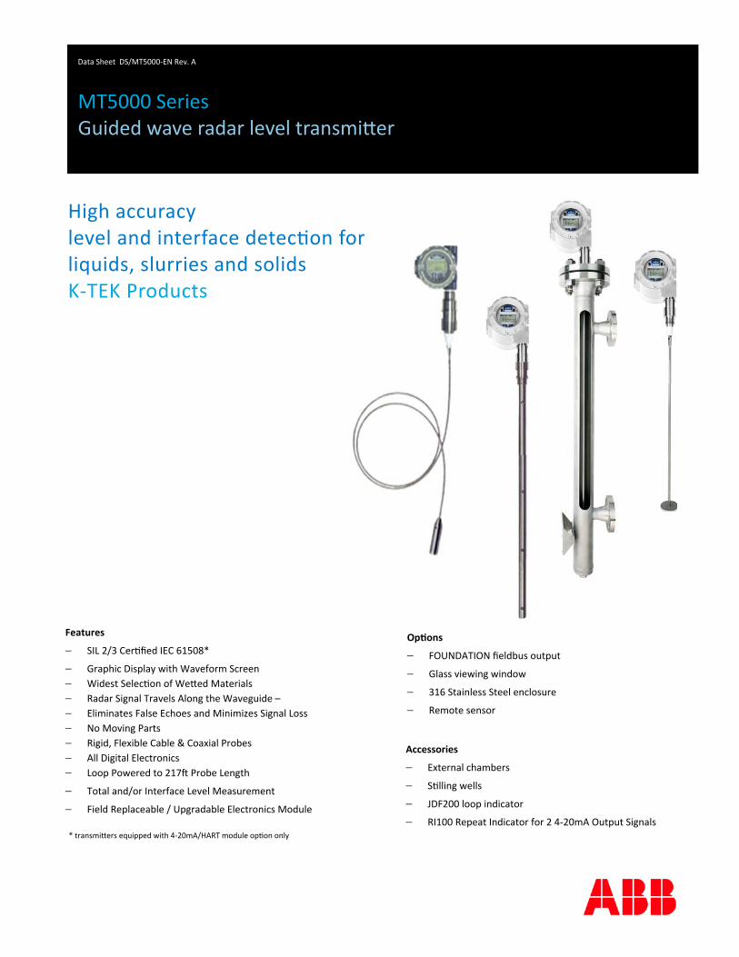
Features
SIL 2/3 Cer fied IEC 61508*
Graphic Display with Waveform Screen
Widest Selec on of We ed Materials
Radar Signal Travels Along the Waveguide –
Eliminates False Echoes and Minimizes Signal Loss
No Moving Parts
Rigid, Flexible Cable & Coaxial Probes
All Digital Electronics
Loop Powered to 217 Probe Length
Total and/or Interface Level Measurement
Field Replaceable / Upgradable Electronics Module
Data Sheet DS/MT5000‐EN Rev. A
MT5000 Series Guided wave radar level transmi er
Op ons
FOUNDATION fieldbus output
Glass viewing window
316 Stainless Steel enclosure
Remote sensor
* transmi ers equipped with 4‐20mA/HART module op on only
Accessories
External chambers
S lling wells
JDF200 loop indicator
RI100 Repeat Indicator for 2 4‐20mA Output Signals
High accuracy level and interface detec on for liquids, slurries and solids K‐TEK Products
2
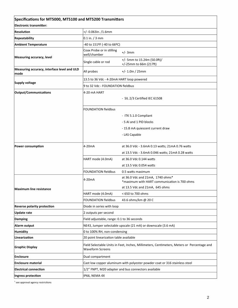
Specifica ons for MT5000, MT5100 and MT5200 Transmi ers
Electronic transmi er:
Resolu on +/‐ 0.063in. /1.6mm
Repeatability 0.1 in. / 3 mm
Ambient Temperature ‐40 to 151ºF (‐40 to 66ºC)
Measuring accuracy, level
Coax Probe or in s lling well/chamber
+/‐ 3mm
Single cable or rod +/‐ 5mm to 15.24m (50.0 )/ +/‐25mm to 66m (217 )
Measuring accuracy, interface level and ULD mode
All probes +/‐ 1.0in / 25mm
Supply voltage 13.5 to 36 Vdc ‐ 4‐20mA HART loop powered
9 to 32 Vdc ‐ FOUNDATION fieldbus
Output/Communica ons 4‐20 mA HART
‐ SIL 2/3 Cer fied IEC 61508
FOUNDATION fieldbus
‐ ITK 5.1.0 Compliant
‐ 5 AI and 1 PID blocks
‐ 15.8 mA quiescent current draw
‐ LAS Capable
Power consump on 4‐20mA at 36.0 Vdc ‐ 3.6mA 0.13 wa s; 21mA 0.76 wa s
at 13.5 Vdc ‐ 3.6mA 0.046 wa s; 21mA 0.28 wa s
HART mode (4.0mA) at 36.0 Vdc 0.144 wa s
at 13.5 Vdc 0.054 wa s
FOUNDATION fieldbus 0.5 wa s maximum
Maximum line resistance
4‐20mA at 36.0 Vdc and 21mA, 1740 ohms* *maximum with HART communica on is 700 ohms
at 13.5 Vdc and 21mA, 645 ohms
HART mode (4.0mA) < 650 to 700 ohms
FOUNDATION fieldbus 43.6 ohms/km @ 20 C
Reverse polarity protec on Diode in series with loop
Update rate 2 outputs per second
Damping Field adjustable, range: 0.1 to 36 seconds
Alarm output NE43, Jumper selectable upscale (21 mA) or downscale (3.6 mA)
Humidity 0 to 100% RH, non‐condensing
Lineariza on 20 point lineariza on table available
Graphic Display Field Selectable Units in Feet, Inches, Millimeters, Cen meters, Meters or Percentage and Waveform Screens
Enclosure Dual compartment
Enclosure material Cast low copper aluminum with polyester powder coat or 316 stainless steel
Electrical connec on 1/2” FNPT, M20 adapter and bus connectors available
Ingress protec on IP66, NEMA 4X
1 see approval agency restric ons
3
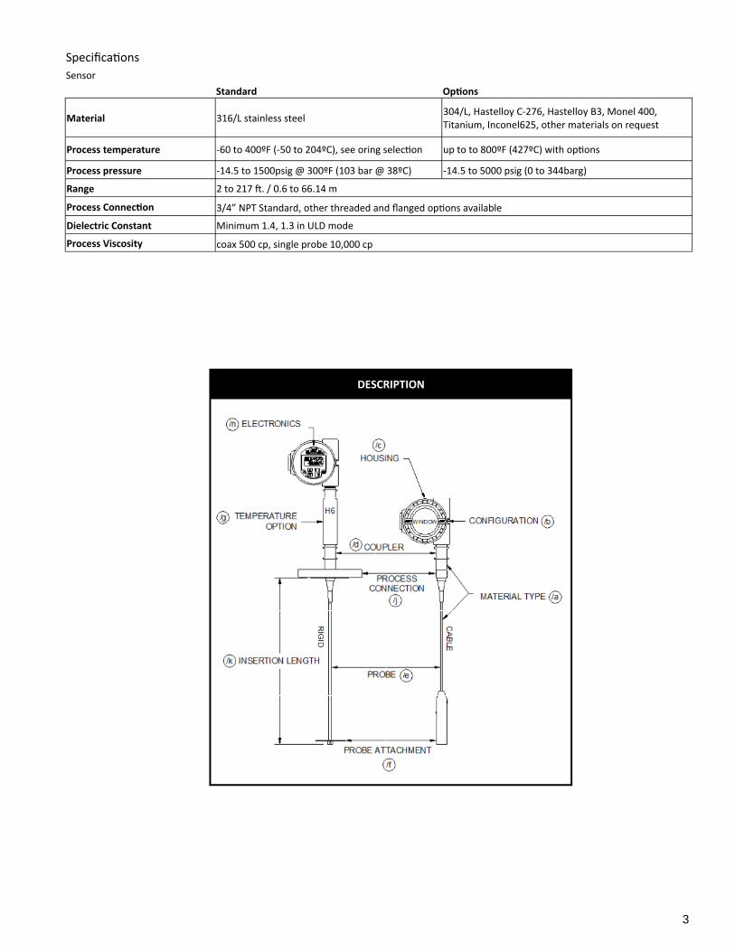
DESCRIPTION
Specifica ons
Sensor Standard Op ons
Material 316/L stainless steel 304/L, Hastelloy C‐276, Hastelloy B3, Monel 400, Titanium, Inconel625, other materials on request
Process temperature ‐60 to 400ºF (‐50 to 204ºC), see oring selec on up to to 800ºF (427ºC) with op ons
Process pressure ‐14.5 to 1500psig @ 300ºF (103 bar @ 38ºC) ‐14.5 to 5000 psig (0 to 344barg)
Range 2 to 217 . / 0.6 to 66.14 m
Process Connec on 3/4” NPT Standard, other threaded and flanged op ons available
Dielectric Constant Minimum 1.4, 1.3 in ULD mode
Process Viscosity coax 500 cp, single probe 10,000 cp
4
MT5100 INTERFACE GUIDELINES
In order to properly detect the level of interface between two liquids using the MT5100, the following rules must be adhered to: 1. One of the following probe and moun ng configura ons must be used:
a. Single rigid rod or flexible cable mounted in a s lling well, external chamber, or exis ng displacer.* b. Coaxial probe mounted into tank, external chamber, or displacer c. Single rigid rod or flexible cable in open vessel with recommended installa on condi ons.
* This is the preferred moun ng configura on to reduce the chance of fouling. 2. Emulsion layers will affect the detec on of an interface level. An emulsion layer may negate an interface level indica on
completely. The MT5100 will read an interface level in the presence of a 3 inch emulsion. Greater emulsion layers may be possible. Please consult factory.
3. The minimum upper fluid thickness must be 4 inches when emulsion is present, and 3 inches with a clean interface. Closer measurement may be possible with calibra on adjustment.
4. The upper fluid dielectric constant must be greater than 1.4 and less than 5. 5. The interface level indica on is a calculated value based par ally upon the dielectric of the upper fluid. The upper fluid
dielectric must remain constant for consistency / accuracy in the interface level indica on. 6. The lower fluid dielectric constant must not be less than 15. 7. If the applica on is a flooded condi on (sensor completely submerged in process), it must remain completely flooded. 8. In a non‐flooded condi on, the upper fluid must not be allowed to enter the upper unmeasurable zone. The upper un‐
measurable zone is typically located within the moun ng nozzle of the vessel. 9. If measuring interface in an external chamber, insure the fluid is allowed to equalize between the vessel and the chamber.
Consult the factory or your local representa ve for assistance. 10. R and RW remote coupler configura ons are not recommended for interface applica ons unless the remote coax is 5 or
less and the probe is a coaxial configura on or in a chamber or s lling well. If the required interface applica on does not fall within the above men oned parameters, please consult the factory for an alternate technology, such as an LMT Series magnetostric ve transmi er or a KM26 magne c level gauge.
GUIDELINES FOR MEASURING with ULD MODE
When measuring low dielectric fluids and bulk solids , it is possible to use the end of probe shi as the target. Requirements for using the end of probe in Ultra Low Dielectric (ULD) mode. 1. The dielectric of the material must be between 1.3 and 3.0. 2. You must have a clear end of probe signal. This may require an addi onal disk on the end of probe in order .to increase
the reflec on 3. The probe type can be cable, rod, or coaxial. 4. Accuracy may be affected if dielectric value changes. 5. If the end of probe is lost in sludge, interface or emulsion, and the end of probe signal is lost, then ULD reading will not
be possible. 6. ULD mode cannot be used where interface or emulsion layer are present.
5
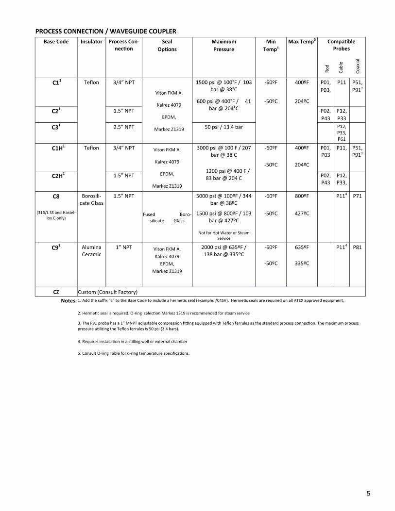
PROCESS CONNECTION / WAVEGUIDE COUPLER
Base Code Insulator Process Con-nec on
Seal
Op ons
Maximum
Pressure
Min
Temp5
Max Temp5 Compa ble Probes
C11 Teflon 3/4” NPT
Viton FKM A,
Kalrez 4079
EPDM,
Markez Z1319
1500 psi @ 100°F / 103 bar @ 38°C
‐60ºF 400ºF P01,
P03,
P11 P51,
P917
600 psi @ 400°F / 41 bar @ 204°C
‐50ºC 204ºC
C21 1.5” NPT P02,
P43
P12,
P33
C31 2.5” NPT 50 psi / 13.4 bar P12, P33, P61
C1H1 Teflon 3/4” NPT Viton FKM A,
Kalrez 4079
EPDM,
Markez Z1319
3000 psi @ 100 F / 207 bar @ 38 C
1200 psi @ 400 F / 83 bar @ 204 C
‐60ºF 400ºF P01, P03
P11, P51, P913
‐50ºC 204ºC
C2H1 1.5” NPT P02, P43
P12, P33,
C8 Borosili‐cate Glass
1.5” NPT
Fused Boro‐silicate Glass
5000 psi @ 100ºF / 344 bar @ 38ºC
‐60ºF 800ºF P114 P71
(316/L SS and Hastel‐loy C only)
1500 psi @ 800ºF / 103 bar @ 427ºC
‐50ºC 427ºC
Not for Hot Water or Steam Service
C92 Alumina Ceramic
1” NPT Viton FKM A,
Kalrez 4079
EPDM,
Markez Z1319
2000 psi @ 635ºF / 138 bar @ 335ºC
‐60ºF
‐50ºC
635ºF
335ºC
P114 P81
CZ Custom (Consult Factory)
Notes: 1. Add the suffix “S” to the Base Code to include a herme c seal (example: /C4SV). Herme c seals are required on all ATEX approved equipment,
2. Herme c seal is required. O‐ring selec on Markez 1319 is recommended for steam service
3. The P91 probe has a 1” MNPT adjustable compression fi ng equipped with Teflon ferrules as the standard process connec on. The maximum process
pressure u lizing the Teflon ferrules is 50 psi (3.4 bars).
4. Requires installa on in a s lling well or external chamber
5. Consult O‐ring Table for o‐ring temperature specifica ons.
Ro
d
Cab
le
Co
axia
l
6
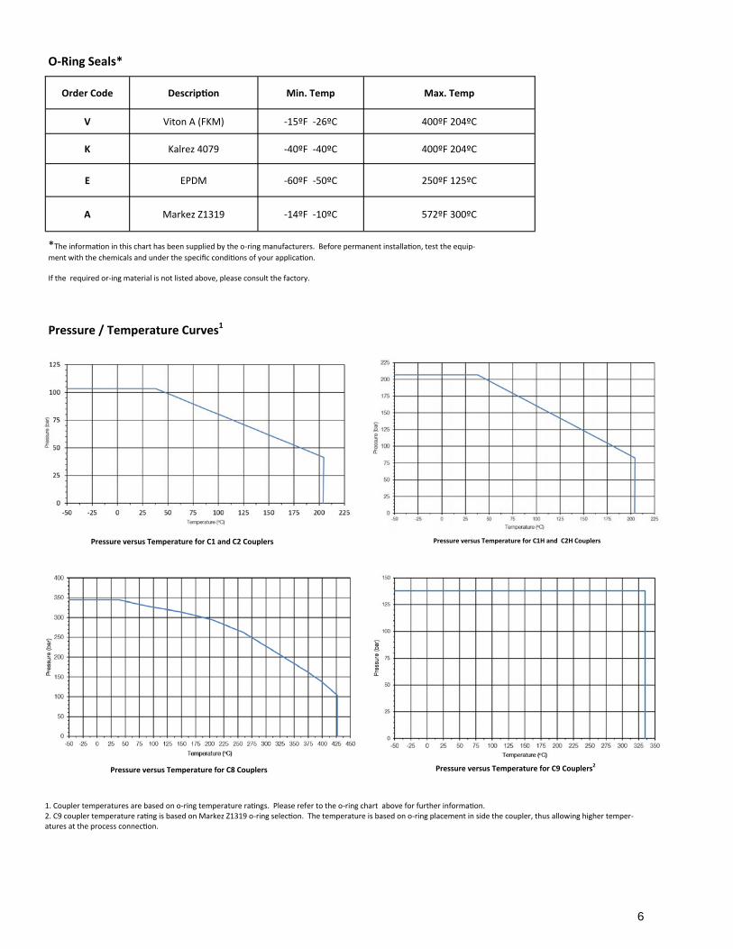
O-Ring Seals*
Order Code Descrip on Min. Temp Max. Temp
V Viton A (FKM) ‐15ºF ‐26ºC 400ºF 204ºC
K Kalrez 4079 ‐40ºF ‐40ºC 400ºF 204ºC
E EPDM ‐60ºF ‐50ºC 250ºF 125ºC
A Markez Z1319 ‐14ºF ‐10ºC 572ºF 300ºC
Pressure versus Temperature for C1 and C2 Couplers Pressure versus Temperature for C1H and C2H Couplers
Pressure versus Temperature for C8 Couplers Pressure versus Temperature for C9 Couplers2
Pressure / Temperature Curves1
*The informa on in this chart has been supplied by the o‐ring manufacturers. Before permanent installa on, test the equip‐
ment with the chemicals and under the specific condi ons of your applica on. If the required or‐ing material is not listed above, please consult the factory.
1. Coupler temperatures are based on o‐ring temperature ra ngs. Please refer to the o‐ring chart above for further informa on. 2. C9 coupler temperature ra ng is based on Markez Z1319 o‐ring selec on. The temperature is based on o‐ring placement in side the coupler, thus allowing higher temper‐atures at the process connec on.
7
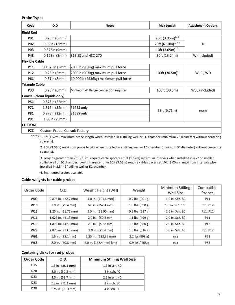
Cable weights for cable probes
Order Code O.D. Weight Height (WH) Weight Minimum S lling
Well Size Compa ble
Probes
W09 0.875 in. (22.2 mm) 4.0 in. (101.6 mm) 0.7 lbs (301 g) 1.0 in. Sch. 80 P11
W10 1.0 in. (25.4 mm) 6.0 in. (152.4 mm) 1.3 lbs (590 g) 1.5 in. Sch. 160 P11, P12
W13 1.25 in. (31.75 mm) 3.5 in. (88.90 mm) 0.8 lbs (317 g) 1.5 in. Sch. 80 P11, P12
W16 1.625 in. (41.3 mm) 2.0 in. (50.8 mm) 1.1 lbs (499 g) 2.0 in. Sch. 80 P11
W19 1.875 in. (47.6 mm) 2.0 in. (50.8 mm) 1.5 lbs (680 g) 2.0 in. Sch. 80 P12
W29 2.875 in. (73.3 mm) 1.0 in. (25.4 mm) 1.8 lbs (816 g) 3.0 in. Sch. 40 P11, P12
W61 1.5 in. (38.1 mm) 5.25 in. (133.35 mm) 2.2 ibs (998 g) n/a P61
WS6 2.0 in. (50.8 mm) 6.0 in. (152.4 mm) long 0.9 lbs / 408 g n/a P33
Centering disks for rod probes
Order Code O.D. Minimum S lling Well Size
D15 1.5 in (38.1 mm) 1.5 in sch. 40
D20 2.0 in. (50.8 mm) 2 in sch. 40
D23 2.3 in. (58.7 mm) 2.5 in sch. 40
D28 2.8 in. (71.1 mm) 3 in sch. 80
D38 3.75 in. (95.3 mm) 4 in sch. 80
Probe Types
Code O.D Notes Max Length A achment Op ons
Rigid Rod
P01 0.25in (6mm) 20 (3.05m)1, 3
D P02 0.50in (13mm) 20 (6.10m)2, 3,4
P03 0.375in (9mm) 10 (3.05m)1,3
P43 0.125in (3mm) 316 SS and HSC‐270 50 (15.24m) W (included)
Flexible Cable
P11 0.1875in (5mm) 2000lb (907kg) maximum pull force
100 (30.5m)3 W, E , WD P12 0.25in (6mm) 2000lb (907kg) maximum pull force
P61 0.31in (8mm) 10,000lb (4536kg) maximum pull force
Triangle Cable
P33 0.25in (6mm) Minimum 4” flange connec on required 100 (30.5m) WS6 (included)
Coaxial (clean liquids only)
P51 0.875in (22mm)
22 (6.71m) none P71 1.315in (34mm) 316SS only
P81 0.875in (22mm) 316SS only
P91 1.00in (25mm)
CUSTOM
PZZ Custom Probe, Consult Factory
Notes: 1. 5 (1.52m) maximum probe length when installed in a s lling well or EC chamber (minimum 2” diameter) without centering
spacer(s).
2. 20 (3.05m) maximum probe length when installed in a s lling well or EC chamber (minimum 3” diameter) without centering
spacer(s).
3. Lengths greater than 7 (2.13m) require cable spacers at 5 (1.52m) maximum intervals when installed in a 2” or smaller s lling well or EC chamber. Lengths greater than 10 (3.05m) require cable spacers at 10 (3.05m) maximum intervals when installed in 2.5” ‐ 3” s lling well or EC chamber.
4. Segmented probes available
8
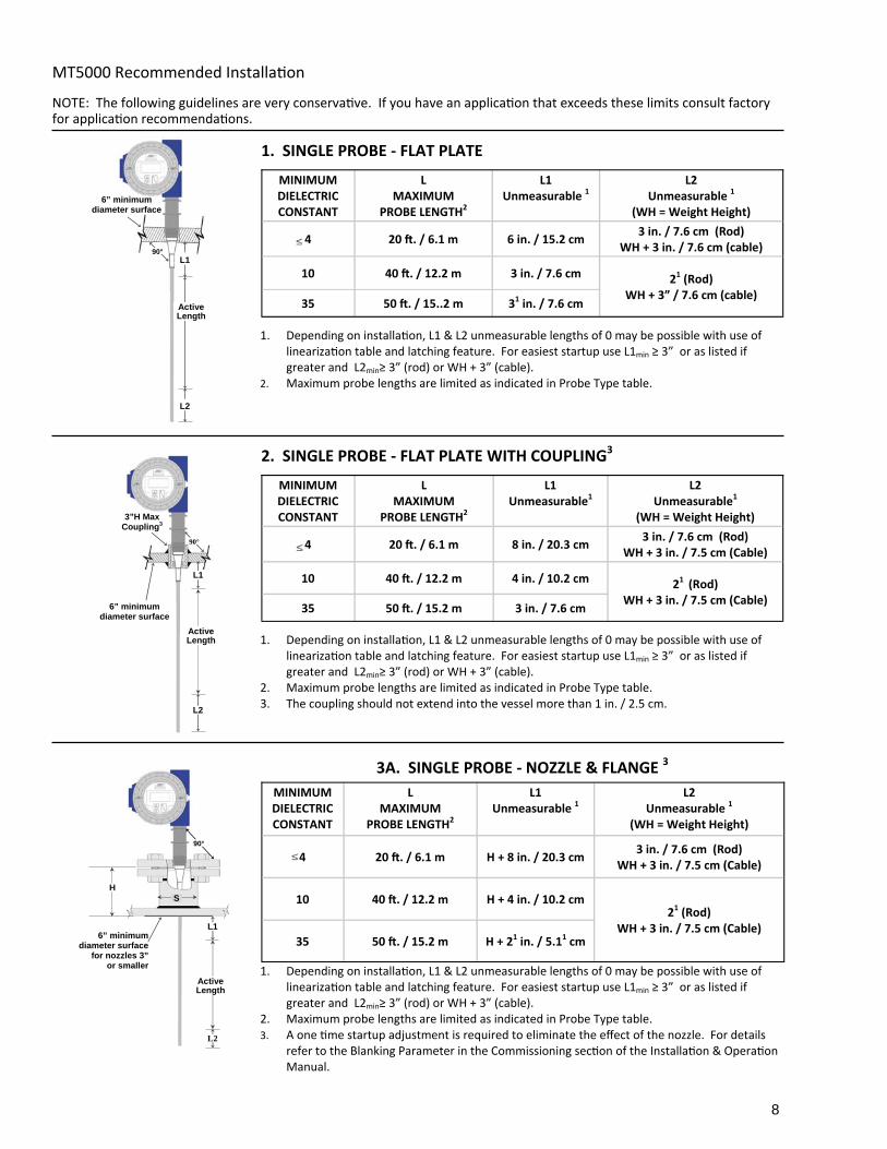
NOTE: The following guidelines are very conserva ve. If you have an applica on that exceeds these limits consult factory for applica on recommenda ons.
1. SINGLE PROBE - FLAT PLATE
MINIMUM DIELECTRIC CONSTANT
L MAXIMUM
PROBE LENGTH2
L1 Unmeasurable 1
L2
Unmeasurable 1
(WH = Weight Height)
4 20 . / 6.1 m 6 in. / 15.2 cm 3 in. / 7.6 cm (Rod)
WH + 3 in. / 7.6 cm (cable)
10 40 . / 12.2 m 3 in. / 7.6 cm
35 50 . / 15..2 m 31 in. / 7.6 cm
21 (Rod) WH + 3” / 7.6 cm (cable)
2. SINGLE PROBE - FLAT PLATE WITH COUPLING3
MINIMUM DIELECTRIC CONSTANT
L MAXIMUM
PROBE LENGTH2
L1 Unmeasurable1
L2 Unmeasurable1
(WH = Weight Height)
4 20 . / 6.1 m 8 in. / 20.3 cm 3 in. / 7.6 cm (Rod)
WH + 3 in. / 7.5 cm (Cable)
10 40 . / 12.2 m 4 in. / 10.2 cm
35 50 . / 15.2 m 3 in. / 7.6 cm
21 (Rod) WH + 3 in. / 7.5 cm (Cable)
3A. SINGLE PROBE - NOZZLE & FLANGE 3
MINIMUM DIELECTRIC CONSTANT
L MAXIMUM
PROBE LENGTH2
L1 Unmeasurable 1
L2
Unmeasurable 1
(WH = Weight Height)
4 20 . / 6.1 m H + 8 in. / 20.3 cm 3 in. / 7.6 cm (Rod)
WH + 3 in. / 7.5 cm (Cable)
10 40 . / 12.2 m H + 4 in. / 10.2 cm
35 50 . / 15.2 m H + 21 in. / 5.11 cm
21 (Rod) WH + 3 in. / 7.5 cm (Cable)
1. Depending on installa on, L1 & L2 unmeasurable lengths of 0 may be possible with use of lineariza on table and latching feature. For easiest startup use L1min ≥ 3” or as listed if greater and L2min≥ 3” (rod) or WH + 3” (cable).
2. Maximum probe lengths are limited as indicated in Probe Type table. 3. A one me startup adjustment is required to eliminate the effect of the nozzle. For details
refer to the Blanking Parameter in the Commissioning sec on of the Installa on & Opera on Manual.
1. Depending on installa on, L1 & L2 unmeasurable lengths of 0 may be possible with use of lineariza on table and latching feature. For easiest startup use L1min ≥ 3” or as listed if greater and L2min≥ 3” (rod) or WH + 3” (cable).
2. Maximum probe lengths are limited as indicated in Probe Type table.
1. Depending on installa on, L1 & L2 unmeasurable lengths of 0 may be possible with use of lineariza on table and latching feature. For easiest startup use L1min ≥ 3” or as listed if greater and L2min≥ 3” (rod) or WH + 3” (cable).
2. Maximum probe lengths are limited as indicated in Probe Type table. 3. The coupling should not extend into the vessel more than 1 in. / 2.5 cm.
L1
L2
Active Length
6” minimum diameter surface
90°
L1
L2
6” minimum diameter surface
3”H Max Coupling3
Active Length
90°
H S
L1
L2
Active Length
6” minimum diameter surface
for nozzles 3” or smaller
90°
MT5000 Recommended Installa on
9
NOTE: The following guidelines are very conserva ve. If you have an applica on that exceeds these limits consult factory for applica on recommenda ons.
MT5000 Recommended Installa on
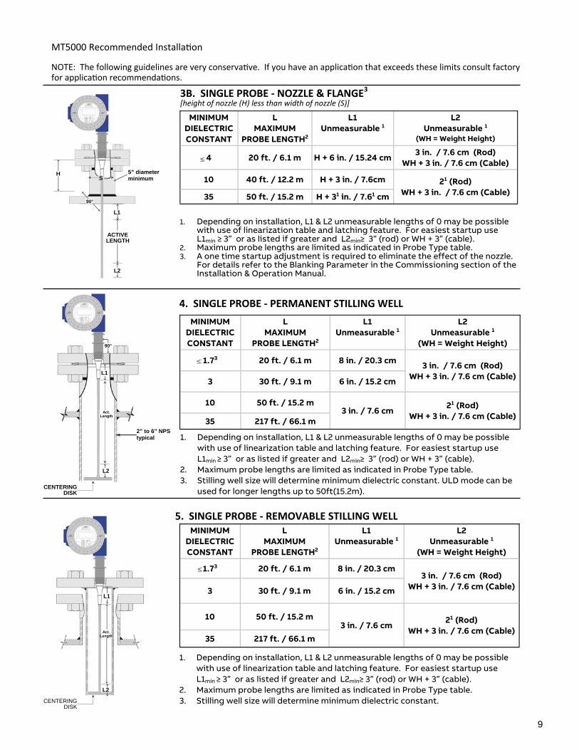
3B. SINGLE PROBE - NOZZLE & FLANGE3 [height of nozzle (H) less than width of nozzle (S)]
4. SINGLE PROBE - PERMANENT STILLING WELL
5. SINGLE PROBE - REMOVABLE STILLING WELL
1. Depending on installation, L1 & L2 unmeasurable lengths of 0 may be possible with use of linearization table and latching feature. For easiest startup use L1min ≥ 3” or as listed if greater and L2min≥ 3” (rod) or WH + 3” (cable).
2. Maximum probe lengths are limited as indicated in Probe Type table. 3. A one time startup adjustment is required to eliminate the effect of the nozzle.
For details refer to the Blanking Parameter in the Commissioning section of the Installation & Operation Manual.
MINIMUM DIELECTRIC CONSTANT
L MAXIMUM
PROBE LENGTH2
L1 Unmeasurable 1
L2
Unmeasurable 1
(WH = Weight Height)
4 20 ft. / 6.1 m H + 6 in. / 15.24 cm 3 in. / 7.6 cm (Rod) WH + 3 in. / 7.6 cm (Cable)
10 40 ft. / 12.2 m H + 3 in. / 7.6cm
35 50 ft. / 15.2 m H + 31 in. / 7.61 cm
21 (Rod) WH + 3 in. / 7.6 cm (Cable)
MINIMUM DIELECTRIC CONSTANT
L MAXIMUM
PROBE LENGTH2
L1 Unmeasurable 1
L2
Unmeasurable 1
(WH = Weight Height)
1.73 20 ft. / 6.1 m 8 in. / 20.3 cm 3 in. / 7.6 cm (Rod) WH + 3 in. / 7.6 cm (Cable) 3 30 ft. / 9.1 m 6 in. / 15.2 cm
10 50 ft. / 15.2 m 21 (Rod) WH + 3 in. / 7.6 cm (Cable) 35 217 ft. / 66.1 m
3 in. / 7.6 cm
1. Depending on installation, L1 & L2 unmeasurable lengths of 0 may be possible with use of linearization table and latching feature. For easiest startup use L1min ≥ 3” or as listed if greater and L2min≥ 3” (rod) or WH + 3” (cable).
2. Maximum probe lengths are limited as indicated in Probe Type table. 3. Stilling well size will determine minimum dielectric constant. ULD mode can be
used for longer lengths up to 50ft(15.2m).
MINIMUM DIELECTRIC CONSTANT
L MAXIMUM
PROBE LENGTH2
L1 Unmeasurable 1
L2
Unmeasurable 1
(WH = Weight Height)
1.73 20 ft. / 6.1 m 8 in. / 20.3 cm 3 in. / 7.6 cm (Rod)
WH + 3 in. / 7.6 cm (Cable) 3 30 ft. / 9.1 m 6 in. / 15.2 cm
10 50 ft. / 15.2 m 21 (Rod) WH + 3 in. / 7.6 cm (Cable)
35 217 ft. / 66.1 m 3 in. / 7.6 cm
1. Depending on installation, L1 & L2 unmeasurable lengths of 0 may be possible with use of linearization table and latching feature. For easiest startup use L1min ≥ 3” or as listed if greater and L2min≥ 3” (rod) or WH + 3” (cable).
2. Maximum probe lengths are limited as indicated in Probe Type table. 3. Stilling well size will determine minimum dielectric constant.
L2
Act. Length
L1
CENTERING DISK
L1
L2
Act. Length
CENTERING DISK
2” to 6” NPS typical
90°
H S
L1
L2
ACTIVE LENGTH
5” diameter minimum
90°
10
MT5000 Recommended Installa on
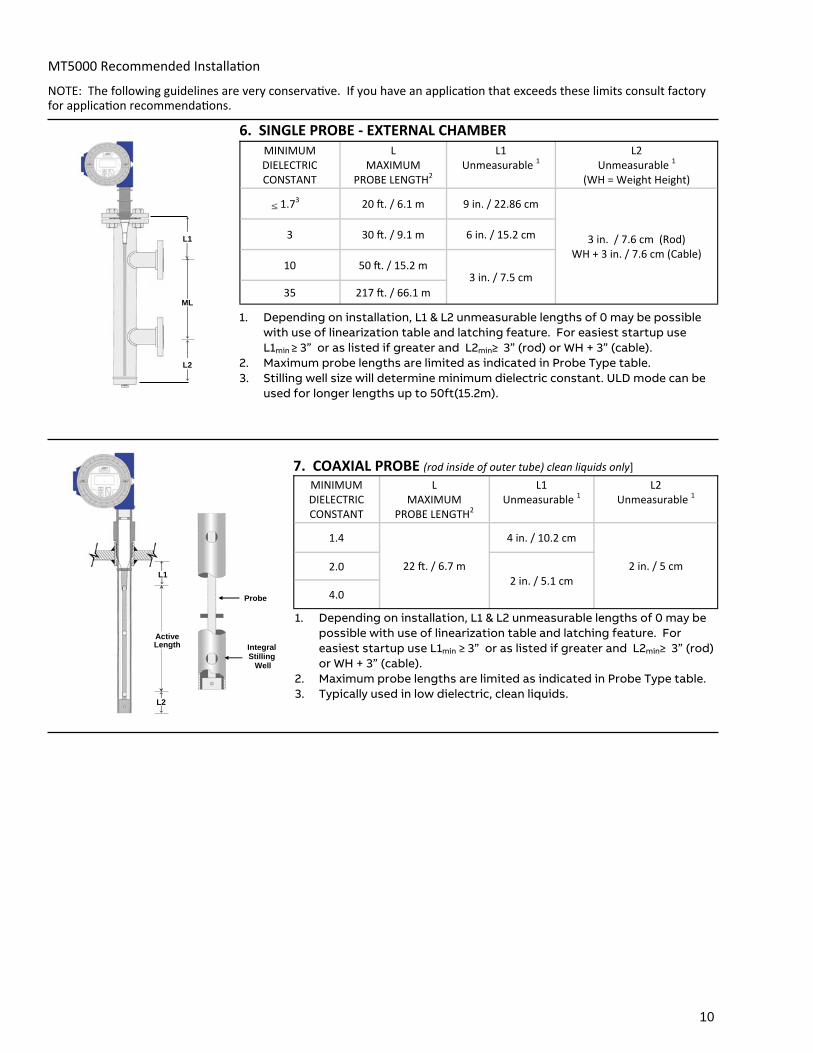
7. COAXIAL PROBE (rod inside of outer tube) clean liquids only]
MINIMUM DIELECTRIC CONSTANT
L MAXIMUM
PROBE LENGTH2
L1 Unmeasurable 1
L2 Unmeasurable 1
1.4
22 . / 6.7 m
4 in. / 10.2 cm
2 in. / 5 cm 2.0
4.0 2 in. / 5.1 cm
L1
L2
Active Length
Probe
Integral Stilling Well
NOTE: The following guidelines are very conserva ve. If you have an applica on that exceeds these limits consult factory for applica on recommenda ons.
6. SINGLE PROBE - EXTERNAL CHAMBER MINIMUM DIELECTRIC CONSTANT
L MAXIMUM
PROBE LENGTH2
L1 Unmeasurable 1
L2
Unmeasurable 1
(WH = Weight Height)
1.73 20 . / 6.1 m 9 in. / 22.86 cm
3 in. / 7.6 cm (Rod) WH + 3 in. / 7.6 cm (Cable)
3 30 . / 9.1 m 6 in. / 15.2 cm
10 50 . / 15.2 m
35 217 . / 66.1 m
3 in. / 7.5 cm
L1
L2
ML
1. Depending on installation, L1 & L2 unmeasurable lengths of 0 may be possible with use of linearization table and latching feature. For easiest startup use L1min ≥ 3” or as listed if greater and L2min≥ 3” (rod) or WH + 3” (cable).
2. Maximum probe lengths are limited as indicated in Probe Type table. 3. Typically used in low dielectric, clean liquids.
1. Depending on installation, L1 & L2 unmeasurable lengths of 0 may be possible with use of linearization table and latching feature. For easiest startup use L1min ≥ 3” or as listed if greater and L2min≥ 3” (rod) or WH + 3” (cable).
2. Maximum probe lengths are limited as indicated in Probe Type table. 3. Stilling well size will determine minimum dielectric constant. ULD mode can be
used for longer lengths up to 50ft(15.2m).
11
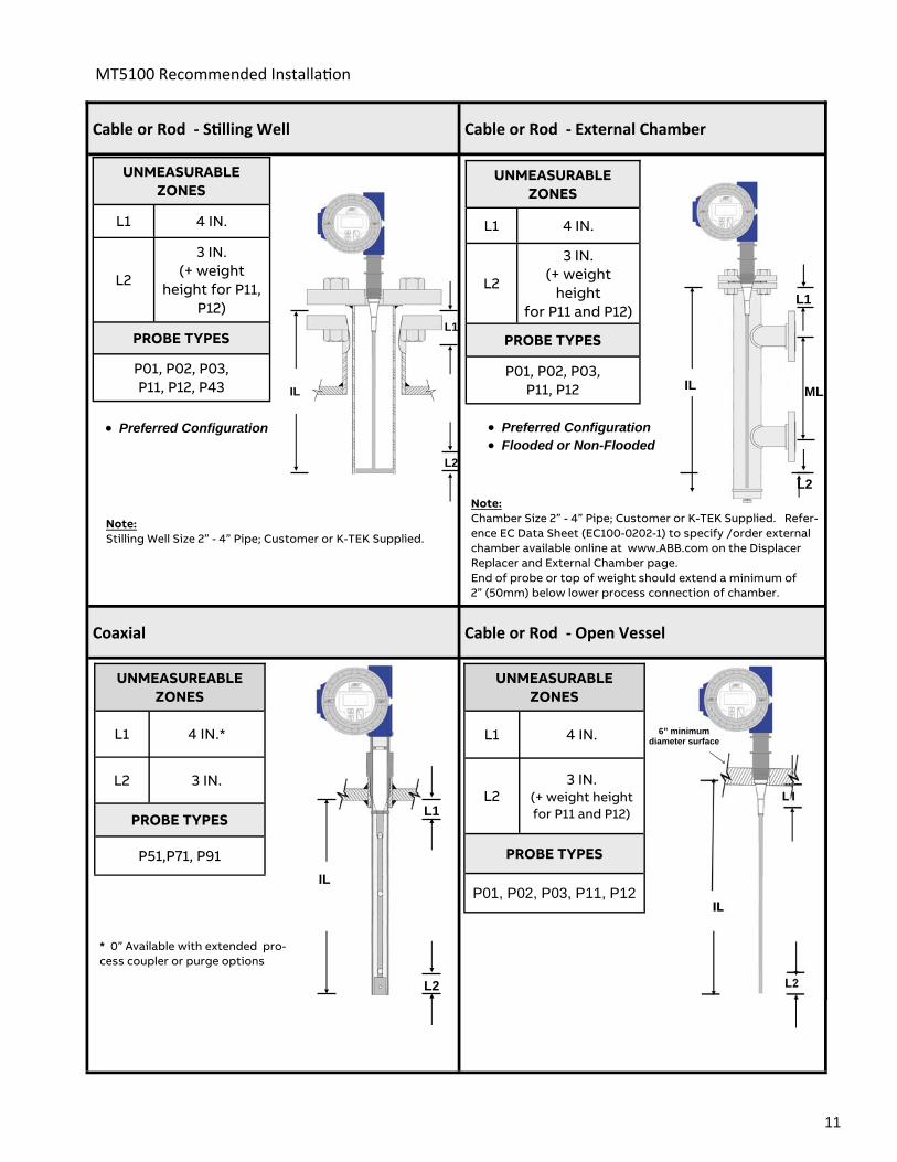
MT5100 Recommended Installa on
UNMEASURABLE ZONES
L1 4 IN.
L2 3 IN.
(+ weight height for P11 and P12)
PROBE TYPES
P01, P02, P03, P11, P12
UNMEASURABLE ZONES
L1 4 IN.
L2
3 IN. (+ weight
height for P11 and P12)
P01, P02, P03, P11, P12
PROBE TYPES
UNMEASURABLE ZONES
L1 4 IN.
L2
3 IN. (+ weight
height for P11, P12)
PROBE TYPES
P01, P02, P03, P11, P12, P43
UNMEASUREABLE ZONES
L1 4 IN.*
L2 3 IN.
PROBE TYPES
P51,P71, P91
Note: Stilling Well Size 2” - 4” Pipe; Customer or K-TEK Supplied.
* 0” Available with extended pro-cess coupler or purge options
IL
L1
L2
IL
L2
L1
IL
L1
L2
Preferred Configuration
Note: Chamber Size 2” - 4” Pipe; Customer or K-TEK Supplied. Refer-ence EC Data Sheet (EC100-0202-1) to specify /order external chamber available online at www.ABB.com on the Displacer Replacer and External Chamber page. End of probe or top of weight should extend a minimum of 2” (50mm) below lower process connection of chamber.
Preferred Configuration Flooded or Non-Flooded
ML IL
L1
L2
Cable or Rod - S lling Well Cable or Rod - External Chamber
Coaxial Cable or Rod - Open Vessel
6” minimum diameter surface
12
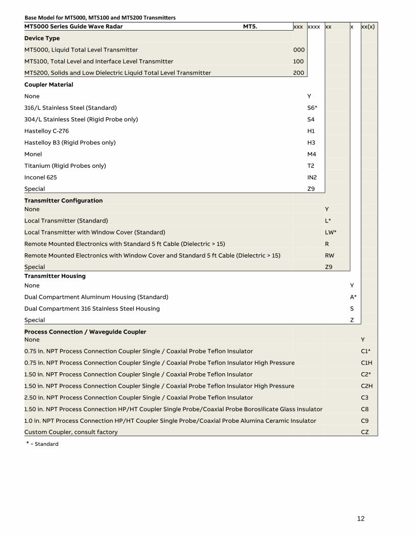
MT5000 Series Guide Wave Radar MT5. xxx xxxx xx x xx(x)
Device Type
MT5000, Liquid Total Level Transmitter 000
MT5100, Total Level and Interface Level Transmitter 100
MT5200, Solids and Low Dielectric Liquid Total Level Transmitter 200
Coupler Material
None Y
316/L Stainless Steel (Standard) S6*
304/L Stainless Steel (Rigid Probe only) S4
Hastelloy C-276 H1
Hastelloy B3 (Rigid Probes only) H3
Monel M4
Titanium (Rigid Probes only) T2
Inconel 625 IN2
Special Z9
Transmitter Configuration None Y
Local Transmitter (Standard) L*
Local Transmitter with Window Cover (Standard) LW*
Remote Mounted Electronics with Standard 5 ft Cable (Dielectric > 15) R
Remote Mounted Electronics with Window Cover and Standard 5 ft Cable (Dielectric > 15) RW
Special Z9 Transmitter Housing
None Y
Dual Compartment Aluminum Housing (Standard) A*
Dual Compartment 316 Stainless Steel Housing S
Special Z
Process Connection / Waveguide Coupler None Y
0.75 in. NPT Process Connection Coupler Single / Coaxial Probe Teflon Insulator C1*
0.75 in. NPT Process Connection Coupler Single / Coaxial Probe Teflon Insulator High Pressure C1H
1.50 in. NPT Process Connection Coupler Single / Coaxial Probe Teflon Insulator C2*
1.50 in. NPT Process Connection Coupler Single / Coaxial Probe Teflon Insulator High Pressure C2H
2.50 in. NPT Process Connection Coupler Single / Coaxial Probe Teflon Insulator C3
1.50 in. NPT Process Connection HP/HT Coupler Single Probe/Coaxial Probe Borosilicate Glass Insulator C8
C9
Custom Coupler, consult factory CZ
1.0 in. NPT Process Connection HP/HT Coupler Single Probe/Coaxial Probe Alumina Ceramic Insulator
Base Model for MT5000, MT5100 and MT5200 Transmi ers
* - Standard
13
Base Model MT5000 Series Guide Wave Radar ordering information continued
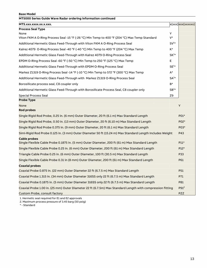
MT5.xxx.xxxx.xx.x.xxx. x(xxx) xxx(xxxxxx)
Process Seal Type None Y
V*
Additional Hermetic Glass Feed-Through with Viton FKM A O-Ring Process Seal SV1*
Kalrez 4079 O-Ring Process Seal -40 °F (-40 °C) Min Temp to 400 °F (204 °C) Max Temp K*
Additional Hermetic Glass Feed-Through with Kalrez 4079 O-Ring Process Seal SK1*
EPDM O-Ring Process Seal -60 °F (-50 °C) Min Temp to 250 °F (125 °C) Max Temp E
Additional Hermetic Glass Feed-Through with EPDM O-Ring Process Seal SE1*
Markez Z1319 O-Ring Process Seal -14 °F (-10 °C) Min Temp to 572 °F (300 °C) Max Temp A*
Additional Hermetic Glass Feed-Through with Markez Z1319 O-Ring Process Seal SA1*
Borosilicate process seal, C8 coupler only B*
Additional Hermetic Glass Feed-Through with Borosilicate Process Seal, C8 coupler only SB1*
Special Process Seal Z9 Probe Type
None Y Rod probes
Single Rigid Rod Probe, 0.25 in. (6 mm) Outer Diameter, 20 ft (6.1 m) Max Standard Length P01*
Single Rigid Rod Probe, 0.50 in. (13 mm) Outer Diameter, 20 ft (6.10 m) Max Standard Length P02*
Single Rigid Rod Probe 0.375 in. (9 mm) Outer Diameter, 20 ft (6.1 m) Max Standard Length P03*
Simi-Rigid Rod Probe 0.125 in. (3 mm) Outer Diameter 50 ft (15.24 m) Max Standard Length Includes Weight P43
Cable probes Single Flexible Cable Probe 0.1875 in. (5 mm) Outer Diameter, 200 ft (61 m) Max Standard Length P11*
Single Flexible Cable Probe 0.25 in. (6 mm) Outer Diameter, 200 ft (61 m) Max Standard Length P12*
Triangle Cable Probe 0.25 in. (6 mm) Outer Diameter, 100 ft (30.5 m) Max Standard Length P33
Single Flexible Cable Probe 0.31 in (8 mm) Outer Diameter, 200 ft (61 m) Max Standard Length P61
Coaxial probes
Coaxial Probe 0.875 in. (22 mm) Outer Diameter 22 ft (6.7.5 m) Max Standard Length P51
Coaxial Probe 1.315 in. (34 mm) Outer Diameter 316SS only 22 ft (6.7.5 m) Max Standard Length P71
Coaxial Probe 0.1875 in. (5 mm) Outer Diameter 316SS only 22 ft (6.7.5 m) Max Standard Length P81
Coaxial Probe 1.00 in. (25 mm) Outer Diameter 22 ft (6.7.5m) Max Standard Length with compression fitting P912
Custom Probe, consult factory PZZ
Viton FKM A O-Ring Process Seal -15 °F (-26 °C) Min Temp to 400 °F (204 °C) Max Temp Standard
1. Hermetic seal required for E1 and E2 approvals 2. Maximum process pressure of 3.45 barg (50 psig) * - Standard
14
Base Model
MT5000 Series Guide Wave Radar ordering informa on con nued
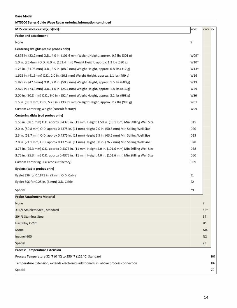
MT5.xxx.xxxx.xx.x.xx(x).x(xxx). xxxx xxxx xx
Probe end a achment
None Y
Centering weights (cable probes only)
0.875 in. (22.2 mm) O.D., 4.0 in. (101.6 mm) Weight Height, approx. 0.7 lbs (301 g) W09*
1.0 in. (25.4mm) O.D., 6.0 in. (152.4 mm) Weight Height, approx. 1.3 lbs (590 g) W10*
1.25 in. (31.75 mm) O.D., 3.5 in. (88.9 mm) Weight Height, approx. 0.8 lbs (317 g) W13*
1.625 in. (41.3mm) O.D., 2.0 in. (50.8 mm) Weight Height, approx. 1.1 lbs (499 g) W16
1.875 in. (47.6 mm) O.D., 2.0 in. (50.8 mm) Weight Height, approx. 1.5 lbs (680 g) W19
2.875 in. (73.3 mm) O.D., 1.0 in. (25.4 mm) Weight Height, approx. 1.8 lbs (816 g) W29
2.00 in. (50.8 mm) O.D., 6.0 in. (152.4 mm) Weight Height, approx. 2.2 lbs (998 g) WS6
1.5 in. (38.1 mm) O.D., 5.25 in. (133.35 mm) Weight Height, approx. 2.2 lbs (998 g) W61
Custom Centering Weight (consult factory) W99
Centering disks (rod probes only)
1.50 in. (38.1 mm) O.D. approx 0.4375 in. (11 mm) Height 1.50 in. (38.1 mm) Min S lling Well Size D15
2.0 in. (50.8 mm) O.D. approx 0.4375 in. (11 mm) Height 2.0 in. (50.8 mm) Min S lling Well Size D20
2.3 in. (58.7 mm) O.D. approx 0.4375 in. (11 mm) Height 2.5 in. (63.5 mm) Min S lling Well Size D23
2.8 in. (71.1 mm) O.D. approx 0.4375 in. (11 mm) Height 3.0 in. (76.2 mm) Min S lling Well Size D28
3.75 in. (95.3 mm) O.D. approx 0.4375 in. (11 mm) Height 4.0 in. (101.6 mm) Min S lling Well Size D38
3.75 in. (95.3 mm) O.D. approx 0.4375 in. (11 mm) Height 4.0 in. (101.6 mm) Min S lling Well Size D60
Custom Centering Disk (consult factory) D99
Eyelets (cable probes only)
Eyelet SS6 for 0.1875 in. (5 mm) O.D. Cable E1
Eyelet SS6 for 0.25 in. (6 mm) O.D. Cable E2
Special Z9
Probe A achment Material
None Y
316/L Stainless Steel, Standard S6*
304/L Stainless Steel S4
Hastelloy C‐276 H1
Monel M4
Inconel 600 N2
Special Z9
Process Temperature Extension
Process Temperature 32 °F (0 °C) to 250 °F (121 °C) Standard H0
Temperature Extension, extends electronics addi onal 6 in. above process connec on H6
Special Z9
15
Base Model MT5000 Series Guide Wave Radar ordering information continued
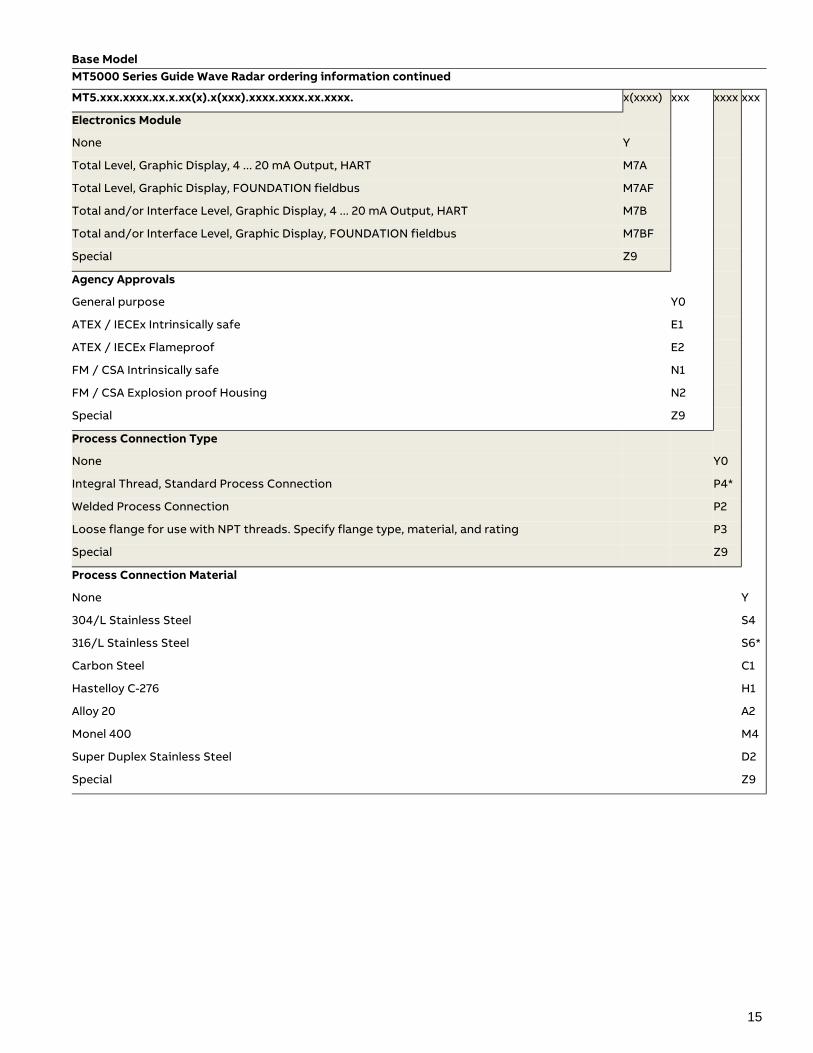
MT5.xxx.xxxx.xx.x.xx(x).x(xxx).xxxx.xxxx.xx.xxxx. x(xxxx) xxx xxxx xxx
Electronics Module
None Y
Total Level, Graphic Display, 4 ... 20 mA Output, HART M7A
Total Level, Graphic Display, FOUNDATION fieldbus M7AF
Total and/or Interface Level, Graphic Display, 4 ... 20 mA Output, HART M7B
Total and/or Interface Level, Graphic Display, FOUNDATION fieldbus M7BF
Special Z9
Agency Approvals
General purpose Y0
ATEX / IECEx Intrinsically safe E1
ATEX / IECEx Flameproof E2
FM / CSA Intrinsically safe N1
FM / CSA Explosion proof Housing N2
Special Z9
Process Connection Type
None Y0
Integral Thread, Standard Process Connection P4*
Welded Process Connection P2
Loose flange for use with NPT threads. Specify flange type, material, and rating P3
Special Z9
Process Connection Material
None Y
304/L Stainless Steel S4
316/L Stainless Steel S6*
Carbon Steel C1
Hastelloy C-276 H1
Alloy 20 A2
Monel 400 M4
Super Duplex Stainless Steel D2
Special Z9
16
Base Model MT5000 Series Guide Wave Radar ordering information continued
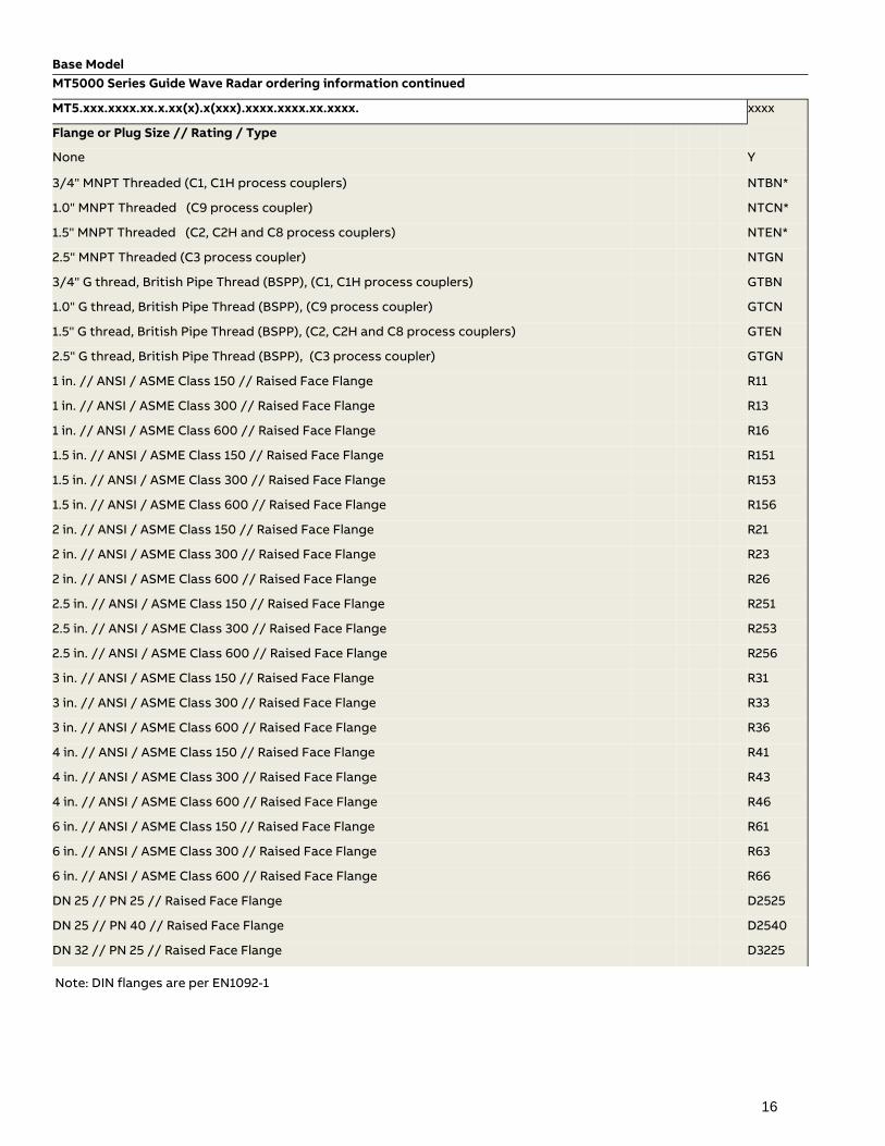
MT5.xxx.xxxx.xx.x.xx(x).x(xxx).xxxx.xxxx.xx.xxxx. xxxx
Flange or Plug Size // Rating / Type
None Y
3/4" MNPT Threaded (C1, C1H process couplers) NTBN*
1.0" MNPT Threaded (C9 process coupler) NTCN*
1.5" MNPT Threaded (C2, C2H and C8 process couplers) NTEN*
2.5" MNPT Threaded (C3 process coupler) NTGN
3/4" G thread, British Pipe Thread (BSPP), (C1, C1H process couplers) GTBN
1.0" G thread, British Pipe Thread (BSPP), (C9 process coupler) GTCN
1.5" G thread, British Pipe Thread (BSPP), (C2, C2H and C8 process couplers) GTEN
2.5" G thread, British Pipe Thread (BSPP), (C3 process coupler) GTGN
1 in. // ANSI / ASME Class 150 // Raised Face Flange R11
1 in. // ANSI / ASME Class 300 // Raised Face Flange R13
1 in. // ANSI / ASME Class 600 // Raised Face Flange R16
1.5 in. // ANSI / ASME Class 150 // Raised Face Flange R151
1.5 in. // ANSI / ASME Class 300 // Raised Face Flange R153
1.5 in. // ANSI / ASME Class 600 // Raised Face Flange R156
2 in. // ANSI / ASME Class 150 // Raised Face Flange R21
2 in. // ANSI / ASME Class 300 // Raised Face Flange R23
2 in. // ANSI / ASME Class 600 // Raised Face Flange R26
2.5 in. // ANSI / ASME Class 150 // Raised Face Flange R251
2.5 in. // ANSI / ASME Class 300 // Raised Face Flange R253
2.5 in. // ANSI / ASME Class 600 // Raised Face Flange R256
3 in. // ANSI / ASME Class 150 // Raised Face Flange R31
3 in. // ANSI / ASME Class 300 // Raised Face Flange R33
3 in. // ANSI / ASME Class 600 // Raised Face Flange R36
4 in. // ANSI / ASME Class 150 // Raised Face Flange R41
4 in. // ANSI / ASME Class 300 // Raised Face Flange R43
4 in. // ANSI / ASME Class 600 // Raised Face Flange R46
6 in. // ANSI / ASME Class 150 // Raised Face Flange R61
6 in. // ANSI / ASME Class 300 // Raised Face Flange R63
6 in. // ANSI / ASME Class 600 // Raised Face Flange R66
DN 25 // PN 25 // Raised Face Flange D2525
DN 25 // PN 40 // Raised Face Flange D2540
DN 32 // PN 25 // Raised Face Flange D3225
Note: DIN flanges are per EN1092-1
17
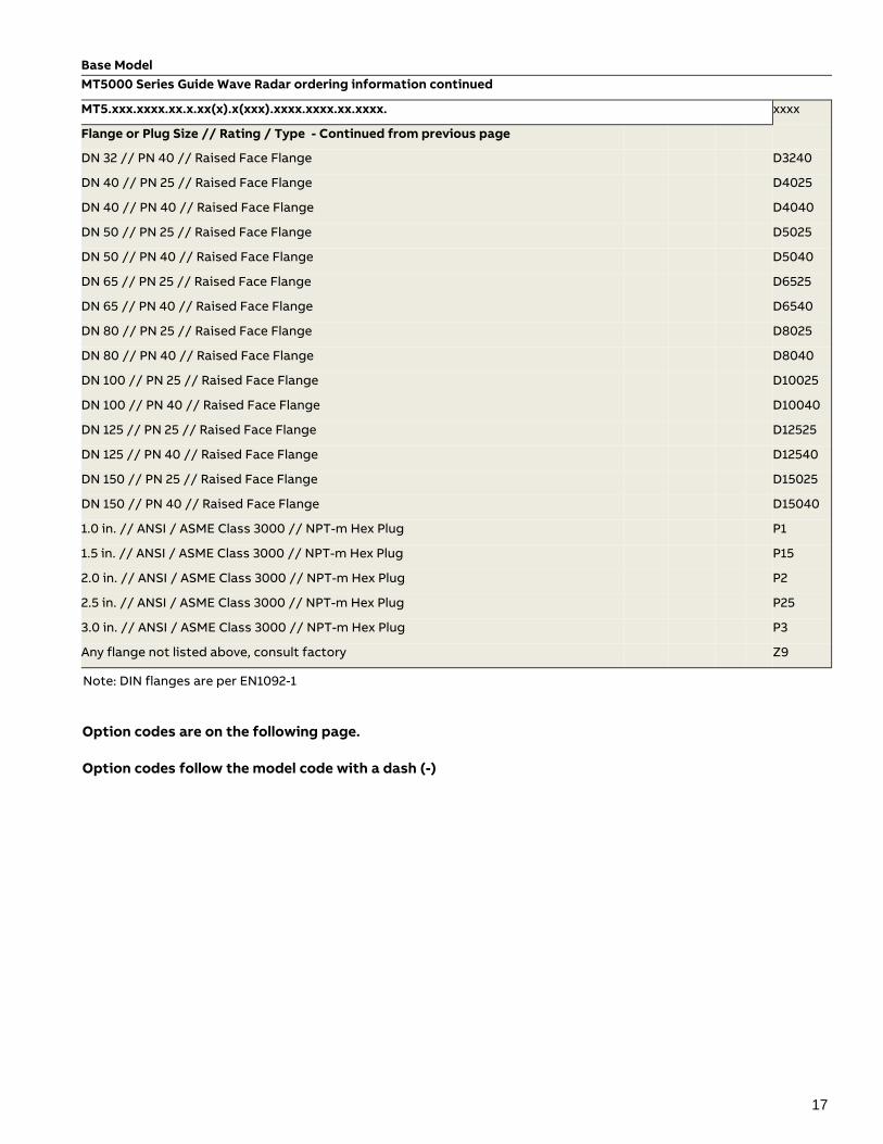
Base Model MT5000 Series Guide Wave Radar ordering information continued
MT5.xxx.xxxx.xx.x.xx(x).x(xxx).xxxx.xxxx.xx.xxxx. xxxx
Flange or Plug Size // Rating / Type - Continued from previous page
DN 32 // PN 40 // Raised Face Flange D3240
DN 40 // PN 25 // Raised Face Flange D4025
DN 40 // PN 40 // Raised Face Flange D4040
DN 50 // PN 25 // Raised Face Flange D5025
DN 50 // PN 40 // Raised Face Flange D5040
DN 65 // PN 25 // Raised Face Flange D6525
DN 65 // PN 40 // Raised Face Flange D6540
DN 80 // PN 25 // Raised Face Flange D8025
DN 80 // PN 40 // Raised Face Flange D8040
DN 100 // PN 25 // Raised Face Flange D10025
DN 100 // PN 40 // Raised Face Flange D10040
DN 125 // PN 25 // Raised Face Flange D12525
DN 125 // PN 40 // Raised Face Flange D12540
DN 150 // PN 25 // Raised Face Flange D15025
DN 150 // PN 40 // Raised Face Flange D15040
1.0 in. // ANSI / ASME Class 3000 // NPT-m Hex Plug P1
1.5 in. // ANSI / ASME Class 3000 // NPT-m Hex Plug P15
2.0 in. // ANSI / ASME Class 3000 // NPT-m Hex Plug P2
2.5 in. // ANSI / ASME Class 3000 // NPT-m Hex Plug P25
3.0 in. // ANSI / ASME Class 3000 // NPT-m Hex Plug P3
Any flange not listed above, consult factory Z9
Option codes are on the following page. Option codes follow the model code with a dash (-)
Note: DIN flanges are per EN1092-1
18
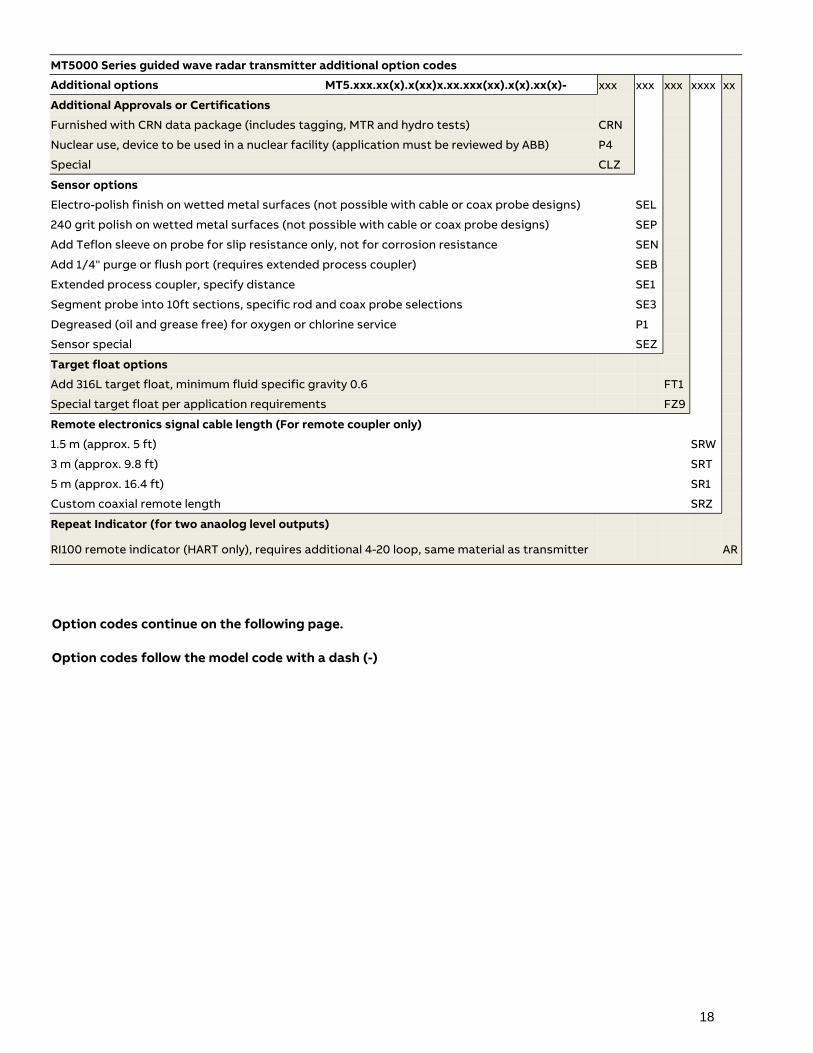
MT5000 Series guided wave radar transmitter additional option codes
Additional options MT5.xxx.xx(x).x(xx)x.xx.xxx(xx).x(x).xx(x)- xxx xxx xxx xxxx xx
Additional Approvals or Certifications
Furnished with CRN data package (includes tagging, MTR and hydro tests) CRN
Nuclear use, device to be used in a nuclear facility (application must be reviewed by ABB) P4
Special CLZ
Sensor options
Electro-polish finish on wetted metal surfaces (not possible with cable or coax probe designs) SEL
240 grit polish on wetted metal surfaces (not possible with cable or coax probe designs) SEP
Add Teflon sleeve on probe for slip resistance only, not for corrosion resistance SEN
Add 1/4" purge or flush port (requires extended process coupler) SEB
Extended process coupler, specify distance SE1
Segment probe into 10ft sections, specific rod and coax probe selections SE3
Degreased (oil and grease free) for oxygen or chlorine service P1
Sensor special SEZ
Target float options Add 316L target float, minimum fluid specific gravity 0.6 FT1 Special target float per application requirements FZ9 Remote electronics signal cable length (For remote coupler only) 1.5 m (approx. 5 ft) SRW 3 m (approx. 9.8 ft) SRT 5 m (approx. 16.4 ft) SR1 Custom coaxial remote length SRZ Repeat Indicator (for two anaolog level outputs)
RI100 remote indicator (HART only), requires additional 4-20 loop, same material as transmitter AR
Option codes continue on the following page. Option codes follow the model code with a dash (-)
19
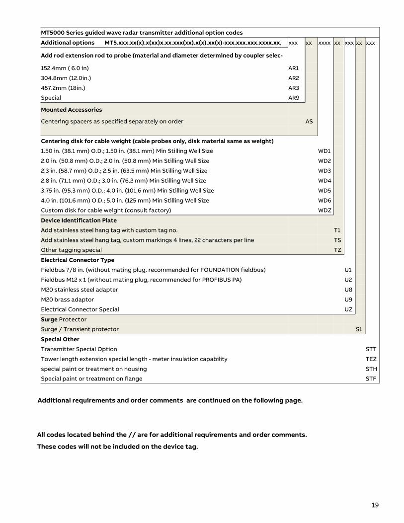
MT5000 Series guided wave radar transmitter additional option codes Additional options MT5.xxx.xx(x).x(xx)x.xx.xxx(xx).x(x).xx(x)-xxx.xxx.xxx.xxxx.xx. xxx xx xxxx xx xxx xx xxx
Add rod extension rod to probe (material and diameter determined by coupler selec-
152.4mm ( 6.0 in) AR1 304.8mm (12.0in.) AR2 457.2mm (18in.) AR3 Special AR9
Mounted Accessories
Centering spacers as specified separately on order AS Centering disk for cable weight (cable probes only, disk material same as weight) 1.50 in. (38.1 mm) O.D.; 1.50 in. (38.1 mm) Min Stilling Well Size WD1 2.0 in. (50.8 mm) O.D.; 2.0 in. (50.8 mm) Min Stilling Well Size WD2 2.3 in. (58.7 mm) O.D.; 2.5 in. (63.5 mm) Min Stilling Well Size WD3 2.8 in. (71.1 mm) O.D.; 3.0 in. (76.2 mm) Min Stilling Well Size WD4 3.75 in. (95.3 mm) O.D.; 4.0 in. (101.6 mm) Min Stilling Well Size WD5 4.0 in. (101.6 mm) O.D.; 5.0 in. (125 mm) Min Stilling Well Size WD6 Custom disk for cable weight (consult factory) WDZ Device Identification Plate Add stainless steel hang tag with custom tag no. T1 Add stainless steel hang tag, custom markings 4 lines, 22 characters per line TS Other tagging special TZ Electrical Connector Type Fieldbus 7/8 in. (without mating plug, recommended for FOUNDATION fieldbus) U1 Fieldbus M12 x 1 (without mating plug, recommended for PROFIBUS PA) U2 M20 stainless steel adapter U8 M20 brass adaptor U9 Electrical Connector Special UZ Surge Protector Surge / Transient protector S1 Special Other
Transmitter Special Option STT
Tower length extension special length - meter insulation capability TEZ
special paint or treatment on housing STH
Special paint or treatment on flange STF
Additional requirements and order comments are continued on the following page.
All codes located behind the // are for additional requirements and order comments.
These codes will not be included on the device tag.
20
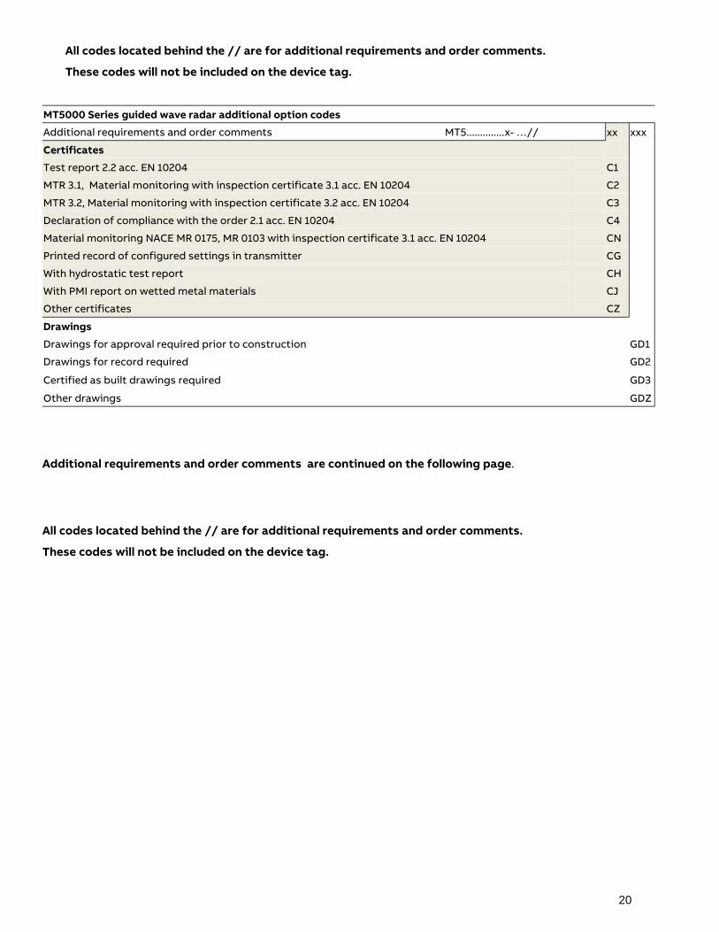
MT5000 Series guided wave radar additional option codes
Additional requirements and order comments MT5..............x- …// xx xxx
Certificates
Test report 2.2 acc. EN 10204 C1
MTR 3.1, Material monitoring with inspection certificate 3.1 acc. EN 10204 C2
MTR 3.2, Material monitoring with inspection certificate 3.2 acc. EN 10204 C3
Declaration of compliance with the order 2.1 acc. EN 10204 C4
Material monitoring NACE MR 0175, MR 0103 with inspection certificate 3.1 acc. EN 10204 CN
Printed record of configured settings in transmitter CG
With hydrostatic test report CH
With PMI report on wetted metal materials CJ
Other certificates CZ
Drawings
Drawings for approval required prior to construction GD1
Drawings for record required GD2
Certified as built drawings required GD3
Other drawings GDZ
All codes located behind the // are for additional requirements and order comments.
These codes will not be included on the device tag.
Additional requirements and order comments are continued on the following page.
All codes located behind the // are for additional requirements and order comments.
These codes will not be included on the device tag.
21
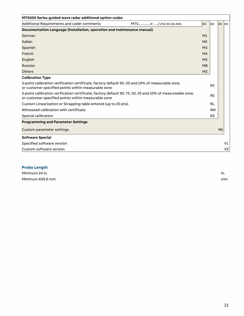
MT5000 Series guided wave radar additional option codes
Additional Requirements and coder comments MT5.............x- …//xx.xx.xx.xxx. xx xx xx xx
Documentation Language (installation, operation and maintenance manual)
German M1
Italian M2
Spanish M3
French M4
English M5
Russian MB
Others MZ
Calibration Type
3-point calibration verification certificate, factory default 90, 50 and 10% of measurable zone, or customer specified points within measurable zone
R3
5-point calibration verification certificate, factory default 90, 75, 50, 25 and 10% of measureable zone, or customer specified points within measurable zone
R5
Custom Linearization or Strapping table entered (up to 20 pts). RL
Witnessed calibration with certificate RW
Special calibration RZ
Programming and Parameter Settings
Custom parameter settings N6
Software Special
Specified software version V1
Custom software version VZ
Probe Length
Minimum 24 in. in.
Minimum 609.6 mm mm
22
Contact us
ABB Inc.
Measurement & Analy cs
3400. Rue Pierre‐Ardouin
Québec, Québec G1P 0B2 CANADA
Office Phone: +1 418.877.2944 ext. 2109
Direct Line : +1 581.628.2109
E‐mail: [email protected]
www.abb.com/level
ABB Measurement & Analy cs
No. 5, Lane 369, Chuangye Road,
Kangqiao Town, Pudong District
Shanghai, 201319, P.R.
China
Tel: +86 10 64231407
Fax: +86 10 64371913
www.abb.com/level
Note
We reserve the right to make technical changes or
modify the contents of this document without prior
no ce. With regard to purchase orders, the agreed
par culars shall prevail. ABB does not accept any
responsibility whatsoever for poten al errors or
possible lack of informa on in this document.
We reserve all rights in this document and in the
subject ma er and illustra ons contained therein. Any
reproduc on, disclosure to third par es or u liza on
of its contents ‐ in whole or in parts – is forbidden
without prior wri en consent of ABB.
Copyright© 2017 ABB
All rights reserved
DS/
MT5
00
0-E
N R
ev. A