Embed Size (px)
Citation preview

7/22/2019 MT9000 and MA Series Cameras_Complete Manual_PC
http://slidepdf.com/reader/full/mt9000-and-ma-series-camerascomplete-manualpc 1/23
AmScope MT USER MANUAL
Version: 3.0.0.1

7/22/2019 MT9000 and MA Series Cameras_Complete Manual_PC
http://slidepdf.com/reader/full/mt9000-and-ma-series-camerascomplete-manualpc 2/23
Operation Manual of AmScope MT
1
TABLE OF CONTENTS
Introduction 2
Precautions 2
I. Software & Driver Installation 3
II. Using your camera for the first time 4
III. Getting live video on screen 4
IV. Live streaming video tools 5
V.
Introduction to image processing 9a. Standard toolbar 9
b. Measurement toolbar 10
c. Image toolbar 12
VI. Calibration Wizard 14
VII. Managing calibrations 16
VIII. Advanced image processing functions 18
a.
Image menu 18
b. Filters menu 20

7/22/2019 MT9000 and MA Series Cameras_Complete Manual_PC
http://slidepdf.com/reader/full/mt9000-and-ma-series-camerascomplete-manualpc 3/23
Operation Manual of AmScope MT
2
Introduction
Congratulations on the purchase of your new AmScope Microscope Camera! This manual is
designed for the MT series camera and software. The MT series camera is compatible with
microscopes equipped with 23mm, 30mm, 30.5mm, or C-mount trinocular (photo) ports. If
your microscope does not have a trinocular port, it is still possible to use the camera byinserting it into the 23mm, 30mm, or 30.5mm eyetube of the microscope. The MT series
software and driver is compatible with Windows based PC’s.
Please take a few minutes to familiarize yourself with the features and functions of your new
microscope camera. Do keep in mind that there may be slight variations between the
graphics and step-by-step instructions provided in this manual and what you see on your PC
screen while using the AmScope MT software. Because we are continually working to
improve our products, this manual is only meant to provide general guidelines for use and
operation. If you want more information on microscopes, cameras, parts, and accessories,
please visit our website at:
www.AmScope.com
We recommend that you study this manual thoroughly before operating the microscope
camera and that you keep it on hand for future reference. If you have any doubts, concerns,
additional questions, or need assistance, please send us an email at:
Please include the camera’s model number and invoice or order #in your email so that we
can identify your model and provide immediate help.
Precautions
(1) As the microscope camera is a precision instrument, always handle it with care. Please
avoid shaking or dropping the device during transportation as this may damage the optical
components of the camera.
(2) Avoid touching the glass lenses of the camera so that oil and dirt from your fingerprints
do not cause distortions in your view.
(3) Do not place the microscope camera in direct sunlight or in high heat. Keep it indoors in
a dry and clean place with temperatures between 32°-100°F (0°-40°C), maximum relative
humidity: 85%
(4) Never immerse the camera in water or any other liquid. To clean the body of the
camera, simply wipe it with a cloth slightly dampened with water. Do not use alcohol. To
clean the lenses of the camera, use only compressed air.
(5) Always replace the protective lens cover after use. This is important since it prevents
dust and particles from accumulating on the lenses of your camera and obstructing your
view.
© Copyright 2010 by AmScope

7/22/2019 MT9000 and MA Series Cameras_Complete Manual_PC
http://slidepdf.com/reader/full/mt9000-and-ma-series-camerascomplete-manualpc 4/23
Operation Manual of AmScope MT
3
I. Software & Driver Installation
Whether you are installing from a disc or from the web, make sure to install both the
application (AmScope MT Software) and the driver that corresponds to your camera’s
model number (MT_ _ _).
FROM DISC1. Insert CD into PC’s CD-rom
2. Wait for your computer to detect the disc, then “Open folder to view files”
3. Double click on the “Application” folder and run the “AmScope MT-en-Setup.exe”
4. Follow the Setup Wizard prompts to install the AmScope MT software
5. When finished, go back and double click on the “Driver” folder. Then run the Driver
Setup.exe that corresponds to the model number of your camera. You can locate
this number on your camera just below its USB plug
6. Follow the Setup Wizard prompts
7. Follow the Device Driver Installation Wizard prompts to install the AmScope MT
driver
8. Setup is now complete!
NOTE: If your AmScope MT camera did not come with a disc or if your disc is
damaged, you may download both the software and driver from our website at
the URL below. Make sure to uninstall the non-working AmScope MT program
before reinstalling from the web.
FROM WEB
1. Go to: www.amscope.com/download-mt
2. Click on the first link “amScope-mt.zip” folder and select “Open with WinRAR.zip”.
Click “OK”
3. Open the folder that begins with “AmScope_MT_3…”
4. Double click the application that begins with “AmScope MT-e…”
5. Follow the Setup Wizard prompts to install the AmScope MT software
6. When finished, go back to www.amscope.com/download-mt and click on the second
link, the “driver.zip” folder. Select “Open with WinRAR.zip”. Click “OK”
7. Double click the application that begins with “MT_ _ _ Driver” making sure that the
numbers correspond to the model number of your camera. You can locate this
number on your camera just below its USB plug
8. Follow the Setup Wizard prompts
9. Follow the Device Driver Installation Wizard prompts to install the AmScope MTdriver.
10. Setup is now complete!

7/22/2019 MT9000 and MA Series Cameras_Complete Manual_PC
http://slidepdf.com/reader/full/mt9000-and-ma-series-camerascomplete-manualpc 5/23
Operation Manual of AmScope MT
4
II. Using your camera for the first time
1. Unscrew the lens protector from the camera head. Then carefully peel of the
protective plastic covering underneath.
2. Unscrew the lens protector from the top of the camera tube (near the colored line).
Screw this end into the head of the camera.3. Determine the size of your microscope’s photo port. If it is 23mm in diameter, you
can drop the camera directly into the port after unscrewing the lens protector from
the bottom of the camera tube. If it is 30mm, 30.5mm in diameter, or uses a c-mount,
you will have to use one of the metal adapters that came with your camera to make it
fit snugly into the port.
a. Make sure the numbers on the adapter are right side up when you insert it
into the trinocular port of the microscope
b. You may insert one of the rubber O-rings into the groove of the adapter if
you choose. The O-ring seals the connection between the adapter and the
photo port. This prevents the camera and adapter from moving around once
inserted into the microscope, which gives you a consistent image. However,
it also makes it more difficult to putting on and removing the adapter from
the microscope’s port. Since this a matter of personal preference, using the
O-Ring is optional.
4. Once the camera is attached to the microscope, you may connect it to your PC using
the USB cord.
5. After turning on your microscope and making sure your trinocular port is open, you
are now ready to open the AmScope MT software to make live observations, snap
photos, and record video!
III. Getting live video onscreen
1. Locate the AmScope MT shortcut in the Start Menu, at the bottom left of your
desktop
2. The program will start after you select its icon, and the start page will look like this:

7/22/2019 MT9000 and MA Series Cameras_Complete Manual_PC
http://slidepdf.com/reader/full/mt9000-and-ma-series-camerascomplete-manualpc 6/23
Operation Manual of AmScope MT
5
3. Make sure your camera is attached to the computer via the USB cable.
4. Double-click on the Camera icon to see streaming video from your microscope
camera. This live-view will appear in a new window labeled “AmScope MT” (below).
5. However, if you get this pop up window instead (right), it
means your PC does not detect the camera. In this
case, make sure the correct driver was installed and
double check the USB cord’s connection to the camera
and the PC.
IV. Live streaming video tools
From the live-view window, you may adjust the image’s configuration (white balance, color,
contrast, exposure, cropping, etc.), snap photos, record video, and adjust photo and video sett ing
using the buttons on the lower left-hand corner of the screen. You may hide/show these buttons
by right clicking the toolbar, or with keyboard shortcut F11.
1. Preview button
Adjusts the resolution of the streaming video
a. High Speed- displays the minimum resolution of the camera,
provides slightly smaller field of view
b. Low Speed- displays the maximum resolution of the camera, provides slightly
wider field of view
2. Snap button
a. Snap- takes a still image from the streaming video on screen and
saves them in .bpm, .jpeg, or .tiff format to the location of your

7/22/2019 MT9000 and MA Series Cameras_Complete Manual_PC
http://slidepdf.com/reader/full/mt9000-and-ma-series-camerascomplete-manualpc 7/23
Operation Manual of AmScope MT
6
choice. Wherever you choose to save the image file, it will also be displayed
on your start page.
b. Snap Config- by selecting “Config…” from the drop down Snap
menu, you may change the settings of the still image that is saved to
the start page
i. Use File Save Dialog- asks you for the name and file format of eachshot you take
ii. Use File Save Config- allows you to preset naming and format rules
for each shot
1. Name by sequence (Name +
numerical value) or by time-stamp
2. Determines the format that the image will be
saved in
iii. Time Lapse- when checked, this features tells the
software to take a series of pictures each time
“Snap” is pressed. “Count” indicates the
number of continuous shots to be taken.
“Space(s)” refers to the amount of seconds between each shot.
iv. Resolution of Snap- use the drop down menu
to select the resolution (size) of the still
images to be taken. It is
recommended that you keep the
resolution constant for calibration
purposes (refer to section VI.
Calibrating Measurements)
v. Use Fine Mode- when checked, this
feature will allow the live image tobe previewed at a high frame-rate,
but will images will be captured at a
low frame-rate. This feature only
comes with select camera models.
vi. Click “OK” to save your settings
3. Start Video button
a. Start Video- starts recording video in .avi format from the
live-view window. Once this button is pressed, it turns into
the Stop Video button. Press it to stop recording video.
b. Start Video Config- by selecting “Config…” from the drop
down Start Video menu, you may change the settings of the
video file that is saved to the start page.
i. Use File Save Dialog- asks you for the name and file format of each
video you take
ii. Use File Save Config- allows you to preset the

7/22/2019 MT9000 and MA Series Cameras_Complete Manual_PC
http://slidepdf.com/reader/full/mt9000-and-ma-series-camerascomplete-manualpc 8/23
Operation Manual of AmScope MT
7
names of videos recorded either by sequence (Name +numerical
value) or by time-stamp
iii. Video Compressor – allows you to choose the compression of video
being recorded. Only certain cameras come with this feature.
iv. Click “OK” to save your settings
4. Auto WB button
Automatic white balance is applied to the streaming video 5. Exposure button
Sets the exposure time for the streaming video, which is reflected by the green progress
bar at the bottom of the live-view screen
i. Auto Exposure format of each shot you take
ii. Manually adjust exposure in milliseconds
NOTE: If you want to record using a long exposure, press the
Long Exposure button on the start page before taking the
video. Please note that this feature only comes with selectcamera models.
6. Cut button
Allows you to zoom in on a portion of the streaming video
a. After clicking the Cut button, use the rainbow colored cursor to click and
drag a box around the area you wish to examine
b. Click “OK” to zoom in on this area, or click “Cancel” to redraw the box

7/22/2019 MT9000 and MA Series Cameras_Complete Manual_PC
http://slidepdf.com/reader/full/mt9000-and-ma-series-camerascomplete-manualpc 9/23
Operation Manual of AmScope MT
8
c. Click the Restore button to return to normal view
7. Property button
Allows users to adjust the camera settings using the pop up “Digital Camera
Sett ing” dialogue box
a. Main tab i. Auto Exposure: automatically adjusts Exposure time (shutter speed)
and Gain (ISO) settings to get the proper amount of light for the
image
ii. Manual Exposure: allows you to
customize the Exposure time (shutter
speed) (Exposure Time) and Gain
(ISO)
iii. White Balance: automatically adjusts
white balance to remove unrealistic
colors (does same thing as White
Balance button)
iv. Default: resets all parameters to their
original setting
b. Image Adjustment tab
i. Image Adjust: adjusts the image’s
Gamma and Contrast on a scale of -20
to +20.
ii. Color Enhancement: checking this box
allows you to change the image’s color
Saturation.
iii. Monochrome (not illustrated):
checking this box allows you tochange the image’s color palette to
grey scale.
iv. Flip: mirrors the image horizontally (H
Flip) and/or vertically (V Flip)
v. Use Back Correction: this feature is
still in development and does not
come with most camera models.
c. Parameter tab
i. RGB: adjusts the image’s color balance
using RGB color channels
ii. Frame Speed: this feature is still in
development and does not come with
most camera models.
iii. Light Frequency: customizes the image
according to your microscope’s light
source (50Hz or 60 Hz)
iv. Image Quality: choose between

7/22/2019 MT9000 and MA Series Cameras_Complete Manual_PC
http://slidepdf.com/reader/full/mt9000-and-ma-series-camerascomplete-manualpc 10/23
Operation Manual of AmScope MT
9
emphasizing smoothness or sharpness in the image
v. Parameter Mode: allows you to save up to 3 different sets of
parameters and load them again later. To save a set of parameters,
select A, B, or C and click “Save”. To load a previously saved set of
parameters, select A, B, or C and click “Load”. Checking “Load this
mode when next start” sets the selected set of parameters as thedefault settings for next time
V. Introduction to image processing
From the AmScope MT start page window, you may select images you have previously captured
for editing. Once you double click an image, it will become a tab in the window (below). From the
image tab, you can make measurements, draw shapes and text boxes, modify and save the
image using the Standard , M easur e , and Image toolbars. You may select which toolbars are
displayed under “View”, or by right-clicking the toolbar. You may also customize which buttons
are included in each toolbar by right-clicking the toolbar and selecting “customize”.
1. Standard Toolbar
Performs functions related to viewing and saving the image
a. Open: opens an existing image file in AmScope MTb. Save As: saves a modified image under a name and format of your
choice
c. Undo: undoes previous steps of image processing
d. Redo: redoes previously undone image processing
e. Move: if the image exceeds the boundaries of the AmScope MT
software window, Move allows you to view different areas of the
image within the window by dragging it with the mouse

7/22/2019 MT9000 and MA Series Cameras_Complete Manual_PC
http://slidepdf.com/reader/full/mt9000-and-ma-series-camerascomplete-manualpc 11/23
Operation Manual of AmScope MT
f. Zoom In and Zoom Out: changes the magnification of
the image on screen without changing the image’s
actual size in pixels (keyboard shortcuts Num+ and
Num -)
g. Help: Provides information on your version of AmScope MT software
(also under Help
About AmScope MT)
2. Measurement Toolbar
Draw and measure the distance between points, the circumference and area of shapes,
angles, and arches. Default distance and area measurements are in pixels. To calibrate pixels
to correspond with real units of measurement (mm, cm, um, etc…), you must first calibrate
your image using the Calibration Wizard (see sectionVI. Calibration Wizard ).
a. Line: draws a line between two points and measures the distance
between them (below).
i. Click once to establish the line’s starting point
ii. Click a second time to establish the line’s ending point
b. Rectangle: draws a rectangle and measures its height, width, area,
and perimeter
i. Click once to establish the rectangle’s fixed corner
ii. Click a second time to establish the rectangle’s opposite corner
c. Circle: draws a circle and calculates its radius, area, and perimeter
i. Click 3 points on the circle’s circumference
ii. A circle will then be drawn based on these 3 points
d. Polygon: draws a polygon and calculates its area and perimeter.
i. Click once to establish the starting point for the polygon
ii. Each single click thereafter indicates a corner
iii. Double click to complete the polygon
e. Angle: draws an angle and measures it in degrees
i. The first click establishes the first arm of the angle

7/22/2019 MT9000 and MA Series Cameras_Complete Manual_PC
http://slidepdf.com/reader/full/mt9000-and-ma-series-camerascomplete-manualpc 12/23
Operation Manual of AmScope MT
11
ii. The second click establishes the vertex of the angle
iii. The third click establishes the second arm of the angle
f. Arc: draws an arc and measures its angle, radius, and lenArc
i. The first click establishes the starting point of the arc
ii. The second click represents any point along the arc
iii. The third click establishes the ending point of the arcg. Point: draws a point with each click of the mouse
h. Remark: adds a text caption on the image where you click by popping
up the Remark window (below). From here you may:
i. Edit your remark
ii. Change the background color of the text box or make it transparent
iii. Edit the font by clicking “ABC”
iv. Click “OK” to save your changes and insert your text into the image
i. Precision: determines the number of decimal points shown for each
measurement j. Table: pops up the Measure Table window, which contains the
specifications of each item drawn in chart format (below). From here
you may:
i. Save as a txt file
ii. Save as an Excel file
iii. Copies information to your clipboard
iv. C
o
p
y
t
h
e
k. L
o
c

7/22/2019 MT9000 and MA Series Cameras_Complete Manual_PC
http://slidepdf.com/reader/full/mt9000-and-ma-series-camerascomplete-manualpc 13/23
Operation Manual of AmScope MT
12
k. Lock: locks in the current calibration settings
l. Select: selects different items on the image
i. Allows you to move the drawn shapes, points, measurement
info, remarks, and scale by dragging them with the mouse
ii. By double-clicking a measurement or its info text box, the Properties
window pops up, which allows you to change the appearance of theShape and Text (below)
m. Delete: allows you to delete previously drawn items and remarks
n. Calibrate: opens the Calibration Wizard, which allows you to make
measurements in real units. For step-by-step guidelines on how to use the
Calibration Wizard, please refer to sectionVI. Calibration Wizard
o. Calibration Table: shows previously saved calibrations from which you may
select one to be applied to your current image. For step-by-step guidelines
on how to use the Calibration Table, refer to sectionVII. Managing
Calibrations
p. To show and hide the scale in the upper right hand corner of the image, go
to MeasureShow Scale Line
3. Image Toolbar
The Image Toolbar makes basic adjustments to the size and appearance of images
a. Rotate: allows you to rotate the image using the pop up the Rotate window
(below). Different ways of rotating the image include:
i. Pressing the 90 degree rotation arrows
ii. Dragging the Angle [degrees] setting bariii. Manually typing in the desired degree of rotation
7/22/2019 MT9000 and MA Series Cameras_Complete Manual_PC
http://slidepdf.com/reader/full/mt9000-and-ma-series-camerascomplete-manualpc 14/23
Operation Manual of AmScope MT
13
b. Flip: flips the image vertically
Please note that the drawn components and measurements you have added
to the image will not be flipped with the image unless you Save As first (in some
cases, you may have to close the newly saved image and reopen)
c. Mirror: flips the image horizontally
Please note that the drawn components and measurements you have added
to the image will not be mirrored with the image unless you Save As first (in some
cases, you may have to close the newly saved image and reopen)
d. Skew: allows you to pivot and skew the image using x and y coordinates
Please note that the drawn components and measurements you have added to
the image will not be skewed accordingly with the image unless you Save As first
(in some cases, you may have to close the newly saved image and reopen)
e. Resample: allows you to change the actual pixel size of the image using eitherSize factor or Pixel Width x Height
i. Size factor- adjusts image size by multiplying it by a number
ii. Pixel Width x Height- adjusts image size by specifying particular
length and/or width dimensions
Please note that the drawn components and measurements you have added to
the image will not get resized with the image unless you Save As first (in some
cases, you may have to close the newly saved image and reopen). Also, please
consider using Resample to adjust your image’s size only after you are done
drawing and making measurements. If you continue to make measurements with
the same calibration setting you were using before resizing, the new
measurements will not be accurate. For more information and detailed calibration
instructions please refer to section VI. Calibration Wizard
f. Crop: allows you to crop an image to reflect your selection.
i. First go to Edit Tracker
ii. Make your selection on the image
iii. Click “Crop”

7/22/2019 MT9000 and MA Series Cameras_Complete Manual_PC
http://slidepdf.com/reader/full/mt9000-and-ma-series-camerascomplete-manualpc 15/23
Operation Manual of AmScope MT
14
However, the drawn components and measurements you have added to the
image will not get cropped accordingly with the image unless you Save As first (in
some cases, you may have to close the newly saved image and reopen)
g. Gray Scale: changes your color image to grey scale (below)
h. Negative: inverts the colors of your image
VI. Calibration Wizard
If you are using a biological (or high-powered) microscope, you will need a micrometer (or micro
ruler) with an overall length of 1mm and increments of 0.01mm (or 10um) to calibrate your
software and convert pixel measurements to real units. It is recommended that the micrometer
used for calibration can be traced to the National Institute of Standards and Technology (NIST)
or a similar organization (NIST micro rulers are available from AmScope at www.amscope.com ).
If you are using a stereo or low-powered microscope, you can do this with a regular ruler.
1. First, focus the micro ruler in your field of view and hook up your camera to your PC
as you would do with a normal slide2. Take a separate picture of the micro ruler for each level of magnification you plan on
making measurements in. Also, please make sure the resolution of the micrometer
image and the resolution of the image to be measured on are the same
For example, if you use the MT camera with the 10X objective to take a
1600x1200 picture of a cell, you must also use the MT camera with the 10x
objective to take a 1600x1200 picture of the micro ruler. This ensures that your
measurements on the image of the cell will be accurate. For instructions on how

7/22/2019 MT9000 and MA Series Cameras_Complete Manual_PC
http://slidepdf.com/reader/full/mt9000-and-ma-series-camerascomplete-manualpc 16/23
Operation Manual of AmScope MT
15
to change the Snap resolution, please refer to section 2-b-iv under section IV. Live
streaming video tools
3. Open the image that you plan to make measurements on with the AmScope MT
4. Once the image is open in its own tab, click “Calibrate” to make the Calibration
Wizard window pop up (below)
a. Click on the Load Image button and select the image
of the micro ruler you wish to use for calibration.
Click “open”
b. The image will now pop up in the Calibration Wizard. Adjust the zoom using
the buttons in the upper left hand corner so that you can clearly see as much
of the image as possiblec. Choose a vertical line on the micro ruler and click once to establish the
starting point of your calibrating measurement. Move your cursor to another
vertical line on the same plane as the first and click to establish the end point
(below):
The greater the distance between the starting and ending points, the more
accurate the measurement

7/22/2019 MT9000 and MA Series Cameras_Complete Manual_PC
http://slidepdf.com/reader/full/mt9000-and-ma-series-camerascomplete-manualpc 17/23
Operation Manual of AmScope MT
16
d. Now, you will fill in the Scale Info. When doing so, make sure you keep in
mind the appropriate unit of measure for the level of magnification you are
using. Once you apply the calibration setting to an image, all measurements
made on the image will reflect the units established in these following steps:
i. Name the calibration: it is helpful to put the
magnification level of the objective here, aswell as the resolution of the image.
For example “10X, 1200*1600”
ii. Length: tells the Calibration Wizard how
long the line is
iii. MeaUnit: make sure the unit of measurement
corresponds to the length you just filled in
e. Once you click “OK” a label will pop up to confirm the name of the
calibration and the length with units you just set (below)
f. If you enter the wrong information or wish to choose another image at any
point, just press the Back key near the bottom of the screen
g. Once you are satisfied with the settings, click “Finish” to save this calibration
and add it to your Calibration Table. The Calibration Wizard closes
automatically, bringing you back to the image tab
5. You do not have to go through the above steps each time you open AmScope MT.
Once you save a calibration in the Calibration Wizard, you can apply it to any image
thereafter. Just be sure that the image you apply the calibration to has the same
magnification level and resolution of the calibration image. This is why it is helpful to
include both the magnification and resolution when naming the calibration (under this
section in step 4-d-i)
VII. Managing Calibrations
To apply a pre-saved calibration sett ing to an image, you will use the Calibration Table to select
the desired calibration. However, when you are selecting which calibration to use, make sure that
the magnification powers and the resolutions of the two images (calibration image and image
being measured) match.

7/22/2019 MT9000 and MA Series Cameras_Complete Manual_PC
http://slidepdf.com/reader/full/mt9000-and-ma-series-camerascomplete-manualpc 18/23
Operation Manual of AmScope MT
17
1. Click “Calibration Table” to access the pop up window from which you can do the
following (below):
a. View pre-saved calibrations
b. Apply pre-saved calibrations to the current image
i. Highlight the desired calibration
ii. Click “Apply To Image”c. Adding and Deleting pre-saved calibrations
i. Deleting
1. Highlight the calibration to be deleted
2. Click “Delete”
ii. Adding
1. Make sure no pre-saved calibrations are highlighted
2. Fill in the Name, Pixels, Length, and select the
Measurement Unit for the new calibration
3. Click “Add”
d. Editing pre-saved calibrations
i. Highlight the calibration to be edited (below)
ii. Make the desired changes to the Name, Pixels, Length, and
Measurement Unit sections on the right. Note that the “Length” will
not recalculate automatically when the unit of measurement is
modified under “MeaUnit”. Therefore, if you wish to change the unit

7/22/2019 MT9000 and MA Series Cameras_Complete Manual_PC
http://slidepdf.com/reader/full/mt9000-and-ma-series-camerascomplete-manualpc 19/23
Operation Manual of AmScope MT
18
of measurement, you must also make sure to change the Length
correspondingly
iii. Click “Save” to preserve changes
2. Checklist for ensuring accurate measurements:
a. The image of the micro ruler used for calibration should have been taken
using the same magnification level as the image being measuredb. The image of the micro ruler used for calibration should be the same
resolution (size) as the image of the image being measured
c. Do not Resample (change the pixel size of) the image being measured until:
i. All measurements have been made
ii. Image has been saved with measurements
Resample should only be used to change the size of the entire image with
completed measurements as a whole. Do not use "Resample" if you are simply
adjusting the view of the image in the middle of making measurements. For this,
use the Zoom buttons instead.
VIII. Advanced image processing functions
In addit ion to the basic image processing functions covered in section V. Intro to Image
Processing, there are many advanced processes that can be applied to your image. These
processes can be found under the “Image” and “Filters” categories above the toolbars. Please
note that the drawn components and measurements you have added to the image will not be
processed along with the rest of the image unless you Save As first (in some cases, you may have
to close the newly saved image and reopen it)
1. Image menu a. Set Transparency: makes a splattering of pixels transparent when you click
the mouse (this feature does not come with all camera models)
b. Remove Transparency: removes transparent pixels created with “Set
Transparency”
c. Alpha Channel
Refers to modifications that are made to the portion of each pixel’s data that is
reserved for transparency information

7/22/2019 MT9000 and MA Series Cameras_Complete Manual_PC
http://slidepdf.com/reader/full/mt9000-and-ma-series-camerascomplete-manualpc 20/23
Operation Manual of AmScope MT
19
i. Opacity: allows you to modify the
opacity/transparency of your image
manually. Doing so prepares the image to
be processed by the Split, Strip, and Invert,
functions.
ii. Remove: removes the transparency effect that the Opacity andCreate from Lightness functions apply to the image
iii. Split: after applying “Create from Lightness” to the image, the Split
function automatically generates a new b/w image from the original
iv. Strip: after applying “Create from Lightness” to the image, Strip
removes the transparency, creating a new, lighter, opaque image
v. Invert: after applying “Create from Lightness” to the image, Invert
reverses the colors of the image
vi. Toggle Alpha Palette: this feature is still in development and does not
come with all camera models
vii. Create from Lightness: based on the level of lightness in the image,
“Create from Lightness” adjusts the image’sopacity so that it is semi-transparent. This
prepares the image to be processed by the Split,
Strip, and Invert, functions.
d. Dither: pops up Dither menu, where you can choose
between different b/w dithering patterns to apply to the
image
7/22/2019 MT9000 and MA Series Cameras_Complete Manual_PC
http://slidepdf.com/reader/full/mt9000-and-ma-series-camerascomplete-manualpc 21/23
Operation Manual of AmScope MT
20
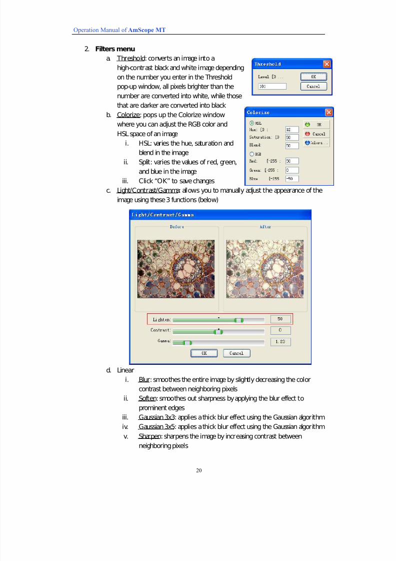
2. Filters menu
a. Threshold: converts an image into a
high-contrast black and white image depending
on the number you enter in the Threshold
pop-up window, all pixels brighter than the
number are converted into white, while thosethat are darker are converted into black
b. Colorize: pops up the Colorize window
where you can adjust the RGB color and
HSL space of an image
i. HSL: varies the hue, saturation and
blend in the image
ii. Split: varies the values of red, green,
and blue in the image
iii. Click “OK” to save changes
c. Light/Contrast/Gamma: allows you to manually adjust the appearance of the
image using these 3 functions (below)
d. Linear
i. Blur: smoothes the entire image by slightly decreasing the color
contrast between neighboring pixels
ii. Soften: smoothes out sharpness by applying the blur effect to
prominent edges
iii. Gaussian 3x3: applies a thick blur effect using the Gaussian algorithm
iv. Gaussian 3x5: applies a thick blur effect using the Gaussian algorithm
v. Sharpen: sharpens the image by increasing contrast between
neighboring pixels
7/22/2019 MT9000 and MA Series Cameras_Complete Manual_PC
http://slidepdf.com/reader/full/mt9000-and-ma-series-camerascomplete-manualpc 22/23
Operation Manual of AmScope MT
21
vi. Edge: underlines an image’s edges to draw attention to boundary
lines
vii. Emboss: creates a raised 3D effect by emphasizing the image’s outline
and decreasing the color values of neighboring areas
e. Non-linear
i. Add Noise: creates random interference pixels in the imageii. Median: adjusts each pixel in the image to reflect its medium intensity
iii. Erode: gives the image a disintegrating effect
iv. Dilate: widens and expands the image
v. Contour: draws find lines along the edges of different colors in the
image, and identifies the contour lines of each color channel
vi. Edge: creates prominent edges in the image based on boundary lines
vii. Jitter: gives the image an undulation effect
f. Circle Transform
i. Pinch: distorts the image by pinching it in the center
ii. Punch: distorts the image by swirling it from the center
iii. Twirl: distorts the image by giving it an overall swirled look
iv. Cylinder: distorts the image by stretching it over a cylinder
v. Bathroom: distorts the image by applying a watery texture to it
g. Pseudo Colors: makes certain details more visible by applying shades of blue
to the image’s negative values and greens and browns to the image’s positive
values
h. Split: splits the color images into several different channels, each with their
own tab, according to the systems below
i. Split to RGB: based on an industry standard that divides color into
red, green, and blue
ii. Split to HSL: based on an industry standard that divides color intohue, saturation, and lightness
iii. Split to YUV: based on the color standard of European TV systems
with Y representing luma and UV representing color difference
iv. Split to YIQ: based on the color standard of North American TV
systems with Y representing grayscale and I and Q representing
color and saturation
v. Split to XYZ: based on the region-growing approach of XYZ space
vi. Split to CMYK: based on a color standard adopted by the printing
industry- cyan, magenta, yellow, black
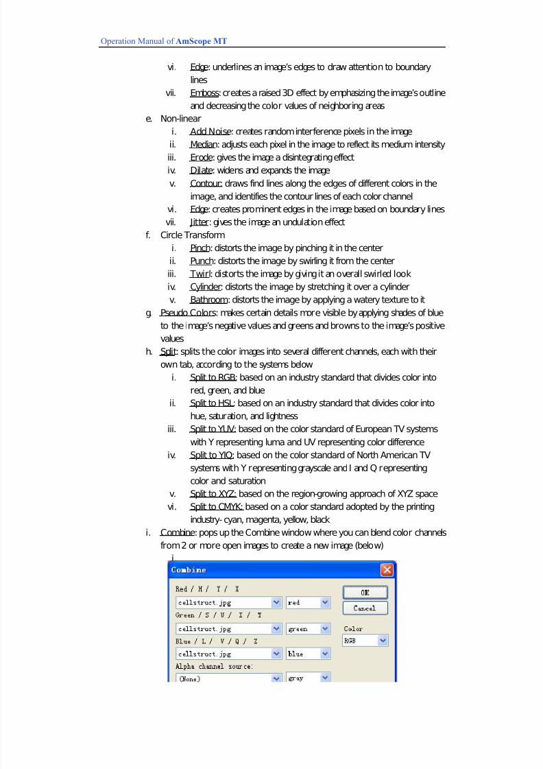
i. Combine: pops up the Combine window where you can blend color channels
from 2 or more open images to create a new image (below)
i.
7/22/2019 MT9000 and MA Series Cameras_Complete Manual_PC
http://slidepdf.com/reader/full/mt9000-and-ma-series-camerascomplete-manualpc 23/23
Operation Manual of AmScope MT
22
j. FFT: stands for “fast Fourier transformation”,
which represents a function that has many
applications, including separating and
removing periodical patterns and analyzing
and enhancing certain periodical patterns
i. Real: selects the image to be transformedii. Imaginary: selects the image towards which the transformation is
oriented
iii. Inverse: checking this option allows the function to invert the image
during transformation
iv. Compute Magnitude: checking this allows the function to calculate
absolute value during the transformation
v. Force FFT: checking this option represents the approval to the
occurrence of Force FFT during the transformation
vi. Click “OK” to initiate these changes
k. Repair: pops up the Repair window where you
can use smart blurring to remove small defects
and artifacts in the image
i. Color: choose between RGB, HSL, YUV,
YIQ, and XYZ color spaces
ii. Radius: normally between 0.01 and 0.5
iii. Iteration: should correspond with the radius so that
(radius*iteration)<1
iv. Click “OK” to initiate these changes
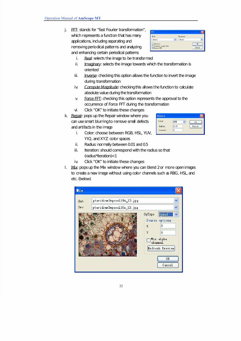
l. Mix: pops up the Mix window where you can blend 2 or more open images
to create a new image without using color channels such as RBG, HSL, and
etc. (below)