Embed Size (px)
Citation preview

M t d M d li fMeasurements and Modeling ofVehicle-to-Vehicle Radio Channels
Johan KåredalDept. of Electrical and Information Technology
Lund University, Sweden

Radio Channel ResearchRadio Channel Research
Main objective: Understand the underlying mechanisms behind theMain objective: Understand the underlying mechanisms behind the propagation of a signal from transmitter to receiver in order to construct a mathematical model for controlled synthesis of channels
E er a e isBasic principle:
Every wave is characterizedby a number of properties:
Multipath propagation
properties: delay-time-of-arrival, Doppler ferquency etcferquency etc.
IEEE VTS Workshop on Wireless Vehicular Communications, Halmstad 2010 2 / 31

OverviewOverview
• Propagation channels– Fundamentals– Research objectives
• Initial measurements – LUND’07 campaignImportant channel charactersics– Important channel charactersics
– Development of a channel model• Follow-up measurements – DRIVEWAY’09 campaignp p g
– Application-specific scenarios– Propagation channels in intersections
• Conclusions
IEEE VTS Workshop on Wireless Vehicular Communications, Halmstad 2010 3 / 31

Cellular vs Vehicle to Vehicle PropagationCellular vs. Vehicle-to-Vehicle Propagation
• Elevated position• Scatterer-free• Static
• Ground-level position• Surrounded by scatterers• DynamicDynamic
• Ground-level position • Different frequency band• Ground-level positionGround level position• Surrounded by scatterers• Dynamic
• Many important scatterersare moving
• Coverage region not a
Ground level position• Surrounded by scatterers• Dynamic
circle around Tx• Vehicle-to-vehicle
channels are subject to f fl i
IEEE VTS Workshop on Wireless Vehicular Communications, Halmstad 2010 4 / 31
faster fluctuations

Doppler Shifts in V2V PropagationDoppler Shifts in V2V Propagation
RXTX RXTX
TX RXTX
TX
RX
RXTX RX
RXTX RXTX
RXTX RXTX
RXTX
IEEE VTS Workshop on Wireless Vehicular Communications, Halmstad 2010 5 / 31
RXTX
Research ObjectivesResearch Objectives
• Obtain a general understanding of vehicle-to-vehicle propagationchannels
U d l i h i– Underlying mechanisms– System impact– Gain from multiple-antenna systemsGain from multiple antenna systems– Antenna/channel interaction
• Build simulations models for system evaluation– Vehicle-to-vehicle propagation channels are different from
many other propagation channels
IEEE VTS Workshop on Wireless Vehicular Communications, Halmstad 2010 6 / 31
OverviewOverview
• Propagation channels– Fundamentals– Research objectives
• Initial measurements – LUND’07 campaignImportant channel charactersics– Important channel charactersics
– Development of a channel model• Follow-up measurements – DRIVEWAY’09 campaignp p g
– Application-specific scenarios– Propagation channels in intersections
• Conclusions
IEEE VTS Workshop on Wireless Vehicular Communications, Halmstad 2010 7 / 31

Vehicle to Vehicle Channel Measurements
• TX/RX mounted on small
Vehicle-to-Vehicle Channel Measurements
Antenna• TX/RX mounted on small trucks
Antenna elements
• 4x4 MIMO measurement campaign at 5.2 GHz
Non omni
• Measurements with cars in same and opposite lanes
Non-omni-directional antenna patternspatterns
IEEE VTS Workshop on Wireless Vehicular Communications, Halmstad 2010 8 / 31

Measured Traffic EnvironmentsMeasured Traffic Environments
1 Hi h ti1. Highway section
• Wall separating directions of traveldirections of travel
• Sound abatement walls
2 Rural road2. Rural road
• Few road-side objects
Littl t ffi• Little traffic
3. Urban street
• Busy traffic
• Buildings, road signs etc.
IEEE VTS Workshop on Wireless Vehicular Communications, Halmstad 2010 9 / 35

General Observations PathlossGeneral Observations - Pathloss
Rural environment: Highway environment:
• Few scatterers contribute to signal• Always line-of-sight conditions• Two ray propagation → predictable
• Multi-path propagation• Line-of-sight sometimes obstructed• Power law dependence (P = P d - n )
IEEE VTS Workshop on Wireless Vehicular Communications, Halmstad 2010 10 / 31
• Two-ray propagation → predictable • Power law dependence (P = P0d n )

General Observations Time/DelayGeneral Observations – Time/Delay
Time-delay characteristics:Time delay characteristics:
t = 0 st = 0 2 st = 0 4 st = 0 6 st = 0 8 st = 1 st = 1 3 st = 1 5 st = 1 7 st = 1 9 st = 2 1 st = 2 3 st = 2 5 st = 2 8 st = 3 st = 3 2 st = 3 4 st = 3 6 st = 3 8 st = 4 1 st = 4 3 st = 4 5 st = 4 7 st = 4 9 st = 5 1 st = 5 3 st = 5 6 sRX t = 5 8 st = 6 st = 6 2 sLOS t = 6 4 st = 6 6 st = 6 9 st = 7 1 st = 7 3 st = 7 5 st = 7 7 st = 7 9 st = 8 1 sDiscrete comp.
Houses, road signs etc.
er
t 0 s
er
t 0.2 s
er
t 0.4 s
er
t 0.6 s
er
t 0.8 s
er
t 1 s
er
t 1.3 s
er
t 1.5 s
er
t 1.7 s
er
t 1.9 s
er
t 2.1 s
er
t 2.3 s
er
t 2.5 s
er
t 2.8 s
er
t 3 s
er
t 3.2 s
er
t 3.4 s
er
t 3.6 s
er
t 3.8 s
er
t 4.1 s
er
t 4.3 s
er
t 4.5 s
er
t 4.7 s
er
t 4.9 s
er
t 5.1 s
er
t 5.3 s
er
t 5.6 s
er
t 5.8 s
er
t 6 s
er
t 6.2 sLOS
er
t 6.4 s
er
t 6.6 s
er
t 6.9 s
er
t 7.1 s
er
t 7.3 s
er
t 7.5 s
er
t 7.7 s
er
t 7.9 s
er
t 8.1 sp
Pow
ePo
we
Pow
ePo
we
Pow
ePo
we
Pow
ePo
we
Pow
ePo
we
Pow
ePo
we
Pow
ePo
we
Pow
ePo
we
Pow
ePo
we
Pow
ePo
we
Pow
ePo
we
Pow
ePo
we
Pow
ePo
we
Pow
ePo
we
Pow
ePo
we
Pow
ePo
we
Pow
ePo
we
Pow
ePo
we
Pow
ePo
we
Pow
e
Diffuse
0 100 200 300 4000 100 200 300 4000 100 200 300 4000 100 200 300 4000 100 200 300 4000 100 200 300 4000 100 200 300 4000 100 200 300 4000 100 200 300 4000 100 200 300 4000 100 200 300 4000 100 200 300 4000 100 200 300 4000 100 200 300 4000 100 200 300 4000 100 200 300 4000 100 200 300 4000 100 200 300 4000 100 200 300 4000 100 200 300 4000 100 200 300 4000 100 200 300 4000 100 200 300 4000 100 200 300 4000 100 200 300 4000 100 200 300 4000 100 200 300 400TX
0 100 200 300 4000 100 200 300 4000 100 200 300 4000 100 200 300 4000 100 200 300 4000 100 200 300 4000 100 200 300 4000 100 200 300 4000 100 200 300 4000 100 200 300 4000 100 200 300 4000 100 200 300 400
Diffuse comp.
Other vehicles
Propagation distance [m]Propagation distance [m]Propagation distance [m]Propagation distance [m]Propagation distance [m]Propagation distance [m]Propagation distance [m]Propagation distance [m]Propagation distance [m]Propagation distance [m]Propagation distance [m]Propagation distance [m]Propagation distance [m]Propagation distance [m]Propagation distance [m]Propagation distance [m]Propagation distance [m]Propagation distance [m]Propagation distance [m]Propagation distance [m]Propagation distance [m]Propagation distance [m]Propagation distance [m]Propagation distance [m]Propagation distance [m]Propagation distance [m]Propagation distance [m]Propagation distance [m]Propagation distance [m]Propagation distance [m]Propagation distance [m]Propagation distance [m]Propagation distance [m]Propagation distance [m]Propagation distance [m]Propagation distance [m]Propagation distance [m]Propagation distance [m]Propagation distance [m]
• Rapidly varying channel• Discrete components carry significant energy and change delay bin with time
IEEE VTS Workshop on Wireless Vehicular Communications, Halmstad 2010 11 / 31
p y g gy g y• Diffuse components following LOS

General Observations Doppler/DelayGeneral Observations – Doppler/Delay
Local scattering function:
-60
-50
-60
-50
-60
-50
-60
-50
-60
-50
-60
-50
-60
-50
-60
-50
-60
-50
-60
-50
-60
-50
-60
-50
-60
-50
-60
-50LOS
Discrete components
Local scattering function:
-80
-70
Pow
er [d
B]
-80
-70
Pow
er [d
B]
-80
-70
Pow
er [d
B]
-80
-70
Pow
er [d
B]
-80
-70
Pow
er [d
B]
-80
-70
Pow
er [d
B]
-80
-70
Pow
er [d
B]
-80
-70
Pow
er [d
B]
-80
-70
Pow
er [d
B]
-80
-70
Pow
er [d
B]
-80
-70
Pow
er [d
B]
-80
-70
Pow
er [d
B]
-80
-70
Pow
er [d
B]
-80
-70
Pow
er [d
B]
0
100
-900
100
-900
100
-900
100
-900
100
-900
100
-900
100
-900
100
-900
100
-900
100
-900
100
-900
100
-900
100
-900
100
-90
Diffuse
-1500-1000-50005001000
200
300
400
500
-1500-1000-50005001000
200
300
400
500
-1500-1000-50005001000
200
300
400
500
-1500-1000-50005001000
200
300
400
500
-1500-1000-50005001000
200
300
400
500
-1500-1000-50005001000
200
300
400
500
-1500-1000-50005001000
200
300
400
500
-1500-1000-50005001000
200
300
400
500
-1500-1000-50005001000
200
300
400
500
-1500-1000-50005001000
200
300
400
500
-1500-1000-50005001000
200
300
400
500
-1500-1000-50005001000
200
300
400
500
-1500-1000-50005001000
200
300
400
500
-1500-1000-50005001000
200
300
400
500
components
10001500500Doppler frequency [Hz]Delay [ns]
10001500500Doppler frequency [Hz]Delay [ns]
10001500500Doppler frequency [Hz]Delay [ns]
10001500500Doppler frequency [Hz]Delay [ns]
10001500500Doppler frequency [Hz]Delay [ns]
10001500500Doppler frequency [Hz]Delay [ns]
10001500500Doppler frequency [Hz]Delay [ns]
10001500500Doppler frequency [Hz]Delay [ns]
10001500500Doppler frequency [Hz]Delay [ns]
10001500500Doppler frequency [Hz]Delay [ns]
10001500500Doppler frequency [Hz]Delay [ns]
10001500500Doppler frequency [Hz]Delay [ns]
10001500500Doppler frequency [Hz]Delay [ns]
10001500500Doppler frequency [Hz]Delay [ns]
• Discrete components: small Doppler spread, but can change delay bin rapidly• Diffuse components: large delay and Doppler spread
IEEE VTS Workshop on Wireless Vehicular Communications, Halmstad 2010 12 / 31
Diffuse components: large delay and Doppler spread• Time-variant Doppler spectrum → Non-stationary conditions

Stationarity TimeStationarity-Time
Highway opposite direction Highway same direction Urban same directionHighway, opposite direction Highway, same direction Urban, same direction
23 ms 1479 ms 1412 ms
The time during which the localscattering function is ”sufficiently constant” is definedas the stationarity time
IEEE VTS Workshop on Wireless Vehicular Communications, Halmstad 2010 13 / 31

Analysis of Diffuse ContributionAnalysis of Diffuse Contribution
Scattering point along roadside
200
50
100
150
1 ]
Doppler characteristics
Amplitude statistics of diffuse
-50
0
50
Dop
pler
shift
[vλ-1characteristics
of diffuse componentscan be modeled
components can be modeled using scatterers
Tap statistics following LOS
-150
-100by scatterersalong roadside
with complex Gaussian path gains
IEEE VTS Workshop on Wireless Vehicular Communications, Halmstad 2010 14 / 31
0 50 100 150 200 250 300-200
Delay [m]

A Geometry Based Stochastic ModelA Geometry-Based Stochastic Model
DiffuseMobile Diffuse scatterers
Mobile discrete scatterers
Static discrete scatterers
Dependent on scatterersantenna pattern
IEEE VTS Workshop on Wireless Vehicular Communications, Halmstad 2010 15 / 31
Adding up all components using different antenna patterns → MIMO channels

Modeling Discrete ComponentsModeling Discrete Components
Analysis of discrete components:1. High-resolution algorithm2 T ki l ith2. Tracking algorithm
94
-92
-90
-94
-92
-90
Discrete components and LOS (!) are fading
102
-100
-98
-96
-94
Pow
er [d
B]
102
-100
-98
-96
-94
Pow
er [d
B]
and LOS (!) are fading
Characterization by:
-108
-106
-104
-102P
110
-108
-106
-104
-102
i. distance decayii. path gain as
stochastic process220 225 230 235 240 245 250 255 260
-110
Delay [m]180 190 200 210 220 230 240 250 260 270 280
-110
Delay [m]
IEEE VTS Workshop on Wireless Vehicular Communications, Halmstad 2010 16 / 31

Channel EmulationChannel Emulation
f f• Example of measured impulse response:
• Example of emulated impulse response:
DiscreteDiscrete components
• Example comparison of measured d l t d t l tiand emulated antenna correlation:
Diffuse components
IEEE VTS Workshop on Wireless Vehicular Communications, Halmstad 2010 17 / 31

Conclusions from Initial MeasurementsConclusions from Initial Measurements
We fo nd thatWe found that:• Vehicle-to-vehicle propagation channels are fundamentally different
from cellular propagation channelsp p g• Vehicle-to-vehicle propagation channels are non-stationary• A geometric-stochastic propagation channel model is suitable
…but also concluded that:• Measurements with trucks are practical but will influence the• Measurements with trucks are practical, but will influence the
measured channel (antenna height)• Measurement conduct (cars in convoy or opposite directions on
h h ) l d b fhighways etc.) is commonly used, but not representative for manyvehicle-to-vehicle applications (e.g., intersection collision avoidance)
M ti ti f f th t !
IEEE VTS Workshop on Wireless Vehicular Communications, Halmstad 2010 18 / 31
→ Motivation for further measurements!

OverviewOverview
• Propagation channels– Fundamentals– Research objectives
• Initial measurements – LUND’07 campaignImportant channel charactersics– Important channel charactersics
– Development of a channel model• Follow-up measurements – DRIVEWAY’09 campaignp p g
– Application-specific scenarios– Propagation channels in intersections
• Conclusions
IEEE VTS Workshop on Wireless Vehicular Communications, Halmstad 2010 19 / 31

MotivationMotivation
• Vehicle-to-vehicle (V2V) communication is envisioned for applications within traffic safetyA t th li ti lli i id t hi h• Amongst those applications are collision avoidance systems, whichare expected to be useful in street intersections
• The properties of the wireless propagation channel is whatp p p p gultimately dictates system performance
• Inital V2V channel measurements typically:d ” l ” t t l t d iti– used ”regular” antenna arrays at an elevated position
– were conducted with cars driving in (a) convoy or (b) oppositedirection
Analyze the propagation channel properties for important scenarios where V2V applications are useful
IEEE VTS Workshop on Wireless Vehicular Communications, Halmstad 2010 20 / 31
Measurement Set UpMeasurement Set-Up
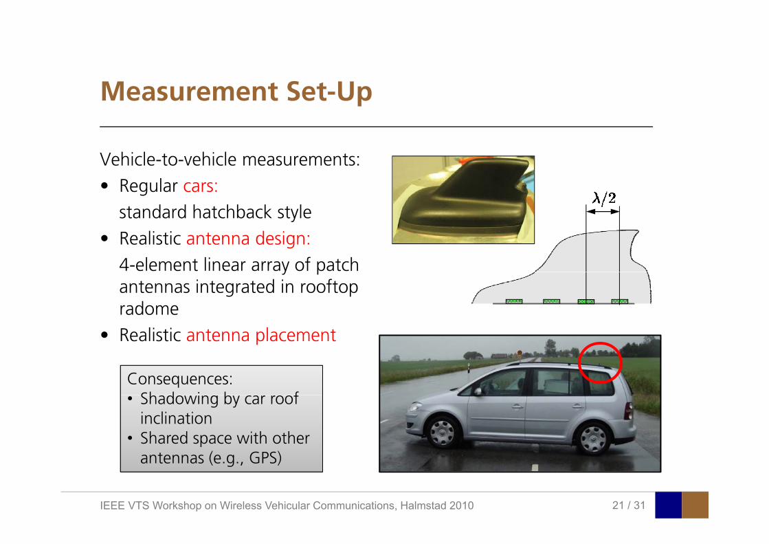
Vehicle-to-vehicle measurements:• Regular cars:
standard hatchback stylestandard hatchback style• Realistic antenna design:
4-element linear array of patchy pantennas integrated in rooftopradome
• Realistic antenna placement• Realistic antenna placement
Consequences:Sh d i b f• Shadowing by car roof inclination
• Shared space with other antennas (e g GPS)
IEEE VTS Workshop on Wireless Vehicular Communications, Halmstad 2010 21 / 31
antennas (e.g., GPS)

Measured ScenariosMeasured Scenarios
Identify scenarios where V2V comunications will be (particularly) useful, e.g.,
lli i id I t ti T l– collision avoidance,– emergency vehicle warning,– hazardous location notification
Intersections Tunnels
Intersections
hazardous location notification,– wrong-way driving warning,– co-operative merging assistance, Merging lanes
Merging lanes
– slow vehicle warning,– lane change assistance
Congestion
Merging lanes
Tunnels
IEEE VTS Workshop on Wireless Vehicular Communications, Halmstad 2010 22 / 31

Measurement ConductMeasurement Conduct
Measurements done whileboth cars approaching an intersection from
di l di iperpendicular directions
Four types of intersections:Four types of intersections:
AntennaAntennaelements two and threethree
IEEE VTS Workshop on Wireless Vehicular Communications, Halmstad 2010 23 / 31
Two Different Urban IntersectionsTwo Different Urban Intersections
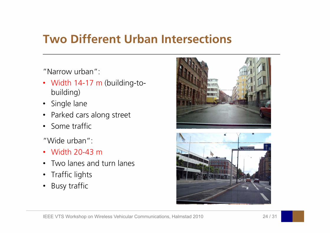
”Narrow urban”:• Width 14-17 m (building-to-
b ildi )building)• Single lane• Parked cars along streetParked cars along street• Some traffic
”Wide urban”:Wide urban :• Width 20-43 m• Two lanes and turn lanes• Traffic lights• Busy traffic
IEEE VTS Workshop on Wireless Vehicular Communications, Halmstad 2010 24 / 31

Time Varying Power Delay ProfilesTime-Varying Power Delay Profiles
Narrow urban (Tx2-Rx2): Wide urban (Tx2-Rx2):
Componentsi i b f
Large increase in numberf t h b th
Strong componentsil bl ”l ”arriving before
line-of-sightof components when bothcars are in intersection
available ”long” before LOS
IEEE VTS Workshop on Wireless Vehicular Communications, Halmstad 2010 25 / 31

A Closer Look at Wide Urban IntersectionA Closer Look at Wide Urban Intersection
Best fit provided012345
Rx 012345
Rx 012345
6
Rx 012345
6
Rx 012345
6
Rx 012345
6
Rx 012345
6
RxBest fit providedby building left of receiver car!
45
S d h h 45
456
6
456
6
7
7-10
456
6
7
7-10
8 910
456
6
7
7-10
8 910
456
6
7
7-10
8 910
0123
4
Tx
Study these pathsin more detail
0123
4
Tx0123
4
Tx0123
4
Tx0123
4
Tx0123
4
Tx0123
4
Tx
Additional propagation Drawing scattering ellipses correspondingAdditional propagationdelay of paths comparedto LOS can be deducedfrom power delay profile
Drawing scattering ellipses correspondingto this delay on a site map for each time instant where the path is visible revealsthe origin of the components
IEEE VTS Workshop on Wireless Vehicular Communications, Halmstad 2010 26 / 31
p y p g p

A Closer Look at Wide Urban cont’dA Closer Look at Wide Urban, cont’d
A high resolution algorithm isA high-resolution algorithm is used to track the time-varying contribution from each patheach path
For long durations, the twopaths contribute to half of the total signalthe total signal
Roadside buildings can provide importantpropagation paths for this type of application.However, the ”narrow urban” scenario did not
IEEE VTS Workshop on Wireless Vehicular Communications, Halmstad 2010 27 / 31
However, the narrow urban scenario did not show same results → dependence on geometry

ComparisonComparison
Define ”distance to collision”as sum of distances to intersecting point: d1+d2
LOS occurs!
”wide urban”wide urban
Few availablepropagation pathsbefore LOS
The difference (3 dB) is similar to contri-bution from buildingd1
The ”wide urban” intersection provides
gin ”wide urban”
The wide urban intersection provides the stronger signal, not due to LOS being availble earlier, but through moreavailable propagation paths!
d2
IEEE VTS Workshop on Wireless Vehicular Communications, Halmstad 2010 28 / 31
available propagation paths!
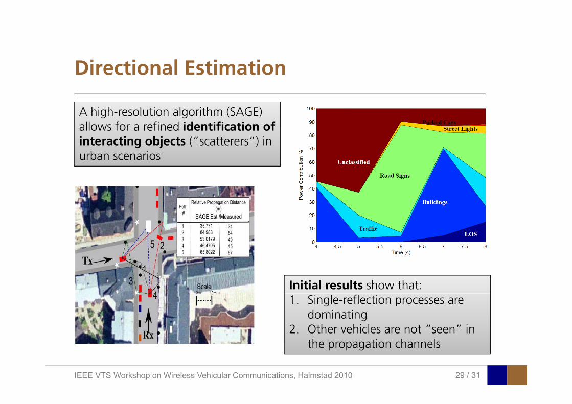
Directional EstimationDirectional Estimation
A high resolution algorithm (SAGE)A high-resolution algorithm (SAGE) allows for a refined identification of interacting objects (”scatterers”) in urban scenariosurban scenarios
Initial results show that:1. Single-reflection processes are
dominating2. Other vehicles are not “seen” in
h i h l
IEEE VTS Workshop on Wireless Vehicular Communications, Halmstad 2010 29 / 31
the propagation channels

OverviewOverview
• Propagation channels– Fundamentals– Research objectives
• Initial measurements – LUND’07 campaignImportant channel charactersics– Important channel charactersics
– Development of a channel model• Follow-up measurements – DRIVEWAY’09 campaignp p g
– Application-specific scenarios– Propagation channels in intersections
• Conclusions
IEEE VTS Workshop on Wireless Vehicular Communications, Halmstad 2010 30 / 31

ConclusionsConclusions
• Vehicle-to-vehicle propagation channels are fundamentallydifferent from cellular channels, especially due to non-stationarity
• Channel models based on assumptions of stationarity cannot be used → a geometry-based model was found suitableg y
• Vehicle-to-vehicle propagation channels can be challenging in it ti h i t t li ti i t d d imany situations where important applications are intended, e.g., in
intersections
• The dependence of antenna placement needs further investigation
IEEE VTS Workshop on Wireless Vehicular Communications, Halmstad 2010 31 / 31

PublicationsPublications
• A. Paier, J. Kåredal, N. Czink, C. Dumard, T. Zemen, F. Tufvesson, A. Molisch, C. F. Mecklenbräuker, ”Characterization of Vehicle-to-Vehicle Radio Channels from Measurements at 5.2GHz,” Wireless Personal Communications, vol. 50, no. 1, pp. 19-29, 2009.
• J. Kåredal, F. Tufvesson, N. Czink, A. Paier, C. Dumard, T. Zemen, C. Mecklenbräuker, A. Molisch, ”A geometry-g ybased stochastic MIMO model for vehicle-to-vehicle communications,” IEEE Transactions on Wireless Communications, vol. 8, no. 7, pp. 3646-3657, 2009.
• A. Molisch, F. Tufvesson, J. Kåredal, C. F. Mecklenbräuker, ”A Survey on Vehicle-to-Vehicle PropagationChannels,” IEEE Wireless Communications, vol. 16, no. 6, pp. 12-22, 2009.J Kå d l F T f T Abb O Kl A P i L B dó A M li h ”R di h l• J. Kåredal, F. Tufvesson, T. Abbas, O. Klemp, A. Paier, L. Bernadó, A. Molisch, ”Radio channel measurements at street intersections for vehicle-to-vehicle applications,” Proc. IEEE Vehicular Technology Conference (VTC2010-spring), Taipei, Taiwan, pp. 1-5, May 16-19, 2010.
• A. Paier, L. Bernadó, J. Kåredal, O. Klemp, A. Kwoczek, ”Overview of vehicle-to-vehicle radio channelmeasurements for collision avoidance applications ” Proc IEEE Vehicular Technology Conference (VTC2010-measurements for collision avoidance applications, Proc. IEEE Vehicular Technology Conference (VTC2010spring), Taipei, Taiwan, pp. 1-5, May 16-19, 2010.
• A. Molisch, F. Tufvesson, J. Kåredal, C. Mecklenbräuker, ”Propagation aspects of vehicle-to-vehiclecommunications - an overview,” Proc. IEEE Radio and Wirless Symposium (RWS), San Diego, CA, USA, pp. 179-182, Jan. 18-22, 2009.
• J. Kåredal, F. Tufvesson, N. Czink, A. Paier, C. Dumard, T. Zemen, C. Mecklenbräuker, A. Molisch, ”Measurement-based modeling of vehicle-to-vehicle MIMO channels,” Proc. IEEE International Conference on Communications (ICC), Dresden, Germany, June 14-18, 2009.
IEEE VTS Workshop on Wireless Vehicular Communications, Halmstad 2010
Publications (cont’d)Publications (cont’d)
• A. Paier, T. Zemen, J. Kåredal, N. Czink, C. Dumard, F. Tufvesson, C. Mecklenbräuker, A. Molisch, ”Spatial diversity and spatial correlation evaluation of measured vehicle-to-vehicle radio channels at 5.2 GHz,” Proc. IEEE Digital Signal Processing Workshop/Signal Processing Education Workshop (DSP/SPE), pp. 326-330, Jan 1-4, 2009.
• L. Bernadó, T. Zemen, A. Paier, J. Kåredal, B. Fleury, ”Parametrization of the local scattering function estimatorfor vehicular-to-vehicular channels,” Proc. IEEE Vehicular Technology Conference (VTC2009-fall), Anchorage, AK, USA, pp. 1-5, Sept. 20-23, 2009.
• A. Paier, T. Zemen, L. Bernado, G. Matz, J. Kåredal, N. Czink, C. Dumard, F. Tufvesson, A. Molisch, C. Mecklenbräuker ”Non WSSUS vehicular channel characterization in highway and urban scenarios at 5 2 GHzMecklenbräuker, Non-WSSUS vehicular channel characterization in highway and urban scenarios at 5.2 GHz using the local scattering function,” Proc. International Workshop on Smart Antennas (WSA), pp. 9-15, 2008.
• L. Bernadó, T. Zemen, A. Paier, G. Matz, J. Kåredal, N. Czink, C. Dumard, F. Tufvesson, M. Hagenauer, A. Molisch, C. F. Mecklenbräuker, ”Non-WSSUS Vehicular Channel Characterization at 5.2 GHz - SpectralDivergence and Time-Variant Coherence Parameters,” Proc. URSI General Assembly, 2008.g , y,
• A. Paier, J. Kåredal, N. Czink, H. Hofstetter, C. Dumard, T. Zemen, F. Tufvesson, C. Mecklenbräuker, A. Molisch, ”First results from car-to-car and car-to-infrastructure radio channel measurements at 5.2GHz,” Proc. IEEE International Symposium on Personal, Indoor and Mobile Radio Communications (PIMRC), Athens, Greece, pp. 1-5, Sept. 3-7, 2007.
d l k f d f l h kl b k• A. Paier, J. Kåredal, N. Czink, H. Hofstetter, C. Dumard, T. Zemen, F. Tufvesson, A. Molisch, C. Mecklenbräuker, ”Car-to-car radio channel measurements at 5 GHz: Pathloss, power-delay profile, and delay-Doppler spectrum,”Proc. IEEE International Symposium on Wireless Communication Systems (ISWCS), Trondheim, Norway, pp. 224-228, Oct. 17-19, 2007.
IEEE VTS Workshop on Wireless Vehicular Communications, Halmstad 2010
Thank you!Thank you!
IEEE VTS Workshop on Wireless Vehicular Communications, Halmstad 2010