Embed Size (px)
Citation preview

M.Tech.: Mechatronics Product Design
Lecture Notes -1
Introduction of Mechatronics Product Design
Mechatronics is a concept of Japanese origin (1970’s) and can be defined as the combination
of Mechanical Engg. with other branches of engineering such as electronics, computer to
control the motions of mechanical systems .Mechatronics product design provides enhanced
value of the mechanical product.
It involves application of electrical, mechanical, control and computer engineering to develop
products, processes and systems with greater flexibility, ease in redesign and ability of
reprogramming. It concurrently includes all these disciplines.
Mechatronics can also be termed as replacement of mechanics with electronics or enhance
mechanical products with electronics. For example, in modern automobiles, mechanical fuel
injection systems are now replaced with electronic fuel injection systems. This replacement
made the automobiles more efficient and less pollutant. Similarly, there are number of
mechatronics products such as digital vernier caliper, digital weighing balance, and automatic
flow of water through tap.
With the help of microelectronics and sensor technology, mechatronics systems are providing
high levels of precision and reliability. It is now possible to move (in x – y plane) the work
table of a modern production machine tool in a step of 0.0001 mm.
By employment of reprogrammable microcontrollers/microcomputers, it is now easy to add
new functions and capabilities to a product or a system. Today’s domestic washing machines
are “intelligent” and four-wheel passenger automobiles are equipped with safety installations
such as air-bags, parking (proximity) sensors, anti-theft electronic keys etc.

Lecture 2
Application of Mechatronics in Automation
Figure 2.1 Operations involved in design and manufacturing of a
product
There are various activities involved in the product manufacturing process. These are shown
in figure 2.1. These activities can be classified into two groups ,i.e., design and
manufacturing activities.It is therefore essential to automate the manufacturing and assembly
operations of a product.
Mechatronics product has good accuracy,lesser wear and cheaper in market. Mechanical
discipline is employed in terms of various machines and mechanisms, where as electrical
engineering as various electric prime movers viz. AC/DC, servo motors and other systems is
used. Control engineering helps in the development of various electronics-based control
systems to enhance or replace the mechanics of the mechanical systems. Computers are
widely used to write various softwares to control the control systems, product design ,
materials and manufacturing resource planning,

Using computer aided design (CAD) / computer aided analysis (CAE) tools, three-
dimensional models of products can easily be developed. These models can then be analyzed
and can be simulated to study their performances using numerical tools. These numerical
tools are being continuously updated or enriched with the real-life performances of the similar
kind of products. These exercises provide an approximate idea about performance of the
product/system to the design team at the early stage of the product development. Based on the
simulation studies, the designs can be modified to achieve better performances. During the
conventional design-manufacturing process, the design assessment is generally carried out
after the production of first lot of the products. This consumes a lot of time, which leads to
longer (in months/years) product development lead-time. Use of CAD–CAE tools saves
significant time in comparison with that required in the conventional sequential design
process.
Mechatronics based automated systems such as automatic inspection and quality assurance,
automatic packaging, record making, and automatic dispatch help to expedite the entire
manufacturing operation. These systems certainly ensure a supply better quality, well packed
and reliable products in the market. Automation in the machine tools has reduced the human
intervention in the machining operation and improved the process efficiency and product
quality. Therefore it is important to study the principles of mechatronics and to learn how to
apply them in the automation of a manufacturing system.

Lecture 3
Mechatronics system
A Mechatronics system integrates various technologies involving sensors, measurement
systems, drives, actuation systems, microprocessor systems and software engineering.
Microprocessor processes or utilizes the information gathered from the sensor system and
generates the signals of appropriate level and suitable kind (current or voltage) which will be
used to actuate the required actuator viz. a hydraulic piston-cylinder device for extension of
piston rod in this case. The microprocessor is programmed on the basis of the principle of
Hooks’ Law. The schematic of microprocessor based equivalent spring mass system is shown
in figure 3.1.
Figure 3.1 Microprocessor based equivalent spring mass system
The input to the system is a force which can be sensed by suitable electro-mechanical sensors
viz. piezo-electric device or strain gauges. These sensors generate either digital signals (0 or
1) or analogue signals (milli-volts or milli-amperes). These signals are then converted into
right form and are attenuated to a right level which can properly be used by the
microprocessor to take generate the actuation signals. Various electronics based auxiliary
devices viz. Analogue-to-Digital Converter (ADC), Digital-to-Analogue Converter (DAC),
Op-amps, Modulators, Linearization circuits, etc. are used to condition the signals which are
either received by the microprocessor from the sensors or are sent to the actuators from the
microprocessor. This mechatronics based spring-mass system has the input signals in the
digital form which are received from the ADC and Piezo-electric sensor. The digital actuation
signals generated by the microprocessors are converted into appropriate analogues signals.
These analogue signals operate the hydraulic pump and control valves to achieve the desired
displacement of the piston-rod.

Lecture 4 Sensors and transducers
Sensors in manufacturing are basically employed to automatically carry out the production
operations as well as process monitoring activities. Measurement system comprises of
sensors, transducers and signal processing devices. Today a wide variety of these elements
and devices are available in the market. For a mechatronics system designer it is quite
difficult to choose suitable sensors/transducers for the desired application(s). It is therefore
essential to learn the principle of working of commonly used sensors/transducers. Sensor
technology has the following important advantages in transforming a conventional
manufacturing unit into a modern one.
1 Sensors alarm the system operators about the failure of any of the sub units of
manufacturing system. It helps operators to reduce the downtime of complete
manufacturing system by carrying out the preventative measures. 2 Reduces requirement of skilled and experienced labors. 3 Ultra-precision in product quality can be achieved.
Sensor
According to the Instrument Society of America, sensor can be defined as “A device which
provides a usable output in response to a specified measurand.”Here, the output is usually an
‘electrical quantity’ and measurand is a ‘physical quantity, property or condition which is to
be measured’. Thus in the case of, say, a variable inductance displacement element, the
quantity being measured is displacement and the sensor transforms an input of displacement
into a change in inductance.

Transducer
It is defined as an element when subjected to some physical change experiences a related
change or an element which converts a specified measurand into a usable output by using a
transduction principle. It can also be defined as a device that converts a signal from one form of energy to another
form. A wire of Constantan alloy (copper-nickel 55-45% alloy) can be called as a sensor because
variation in mechanical displacement (tension or compression) can be sensed as change in
electric resistance. This wire becomes a transducer with appropriate electrodes and input-
output mechanism attached to it. Thus we can say that ‘sensors are transducers’. Sensor/transducers specifications Transducers or measurement systems are not perfect systems. Mechatronics design engineer
must know the capability and shortcoming of a transducer or measurement system to properly
assess its performance. There are a number of performance related parameters of a transducer
or measurement system. These parameters are called as sensor specifications. Sensor specifications inform the user to the about deviations from the ideal behavior of the
sensors. Following are the various specifications of a sensor/transducer system. 1. Range
The range of a sensor indicates the limits between which the input can vary. For example, a
thermocouple for the measurement of temperature might have a range of 10-100 °C. 2. Span The span is difference between the maximum and minimum values of the input. Thus, the
above-mentioned thermocouple will have a span of 90 °C.
3. Error
Error is the difference between the result of the measurement and the true value of the
quantity being measured. A sensor might give a displacement reading of 29.8 mm, when the
actual displacement had been 30 mm, then the error is –0.2 mm.
4. Accuracy The accuracy defines the closeness of the agreement between the actual measurement result
and a true value of the measurand. It is often expressed as a percentage of the full range
output or full–scale deflection.
5. Sensitivity Sensitivity of a sensor is defined as the ratio of change in output value of a sensor to the per
unit change in input value that causes the output change. For example, a general purpose
thermocouple may have a sensitivity of 41 µV/°C.
6. Nonlinearity The nonlinearity indicates the maximum deviation of the actual measured
curve of a sensor from the ideal curve.
7. Resolution

Resolution is the smallest detectable incremental change of input parameter that can be
detected in the output signal. Resolution can be expressed either as a proportion of the full-
scale reading or in absolute terms. For example, if a LVDT sensor measures a displacement
up to 20 mm and it provides an output as a number between 1 and 100 then the resolution of
the sensor device is 0.2 mm. 8. Stability
Stability is the ability of a sensor device to give same output when used to measure a constant
input over a period of time. The term ‘drift’ is used to indicate the change in output that
occurs over a period of time. It is expressed as the percentage of full range output. 9. Repeatability It specifies the ability of a sensor to give same output for repeated applications of same input
value. It is usually expressed as a percentage of the full range output: Repeatability = (maximum – minimum values given) X 10
10. Response time
Response time describes the speed of change in the output on a step-wise change of the
measurand. It is always specified with an indication of input step and the output range for
which the response time is defined. Classification of sensors
Sensors can be classified into various groups according to the factors such as measurand,
application fields, conversion principle, energy domain of the measurand and thermodynamic
considerations. Detail classification of sensors in view of their applications in manufacturing
is as follows.
1. Displacement, position and proximity sensors
a. Potentiometer
b. Strain-gauged element
c. Capacitive element
d. Differential transformers
e. Eddy current proximity sensors
f. Inductive proximity switch
g. Optical encoders
h. Pneumatic sensors
i. Proximity switches (magnetic)
j. Hall effect sensors
2. Velocity and motion
a. Incremental encoder
b. Tachogenerator

c. Pyroelectric sensors
3. Force
a. Strain gauge load cell
4. Fluid pressure
a. Diaphragm pressure gauge
b. Capsules, bellows, pressure tubes
c. Piezoelectric sensors
d. Tactile sensor
3. Liquid flow
Orifice plate
Turbine meter
4. Liquid level
Floats
Differential pressure
5. Temperature
Bimetallic strips
Resistance temperature detectors
Thermistors
Thermo-diodes and transistors
Thermocouples
Light sensors
Photo diodes
Photo resistors
Photo transistor
Lecture-5
Displacement and position sensors Displacement sensors are basically used for the measurement of movement of an object.
Displacement sensors The potentiometer can be of linear or angular type. It works on the principle of conversion of
mechanical displacement into an electrical signal. The sensor has a resistive element and a
sliding contact (wiper). The slider moves along this conductive body, acting as a movable
electric contact. The resistive element is a wire wound track or conductive plastic. The track comprises of
large number of closely packed turns of a resistive wire. Conductive plastic is made up of
plastic resin embedded with the carbon powder. Wire wound track has a resolution of the
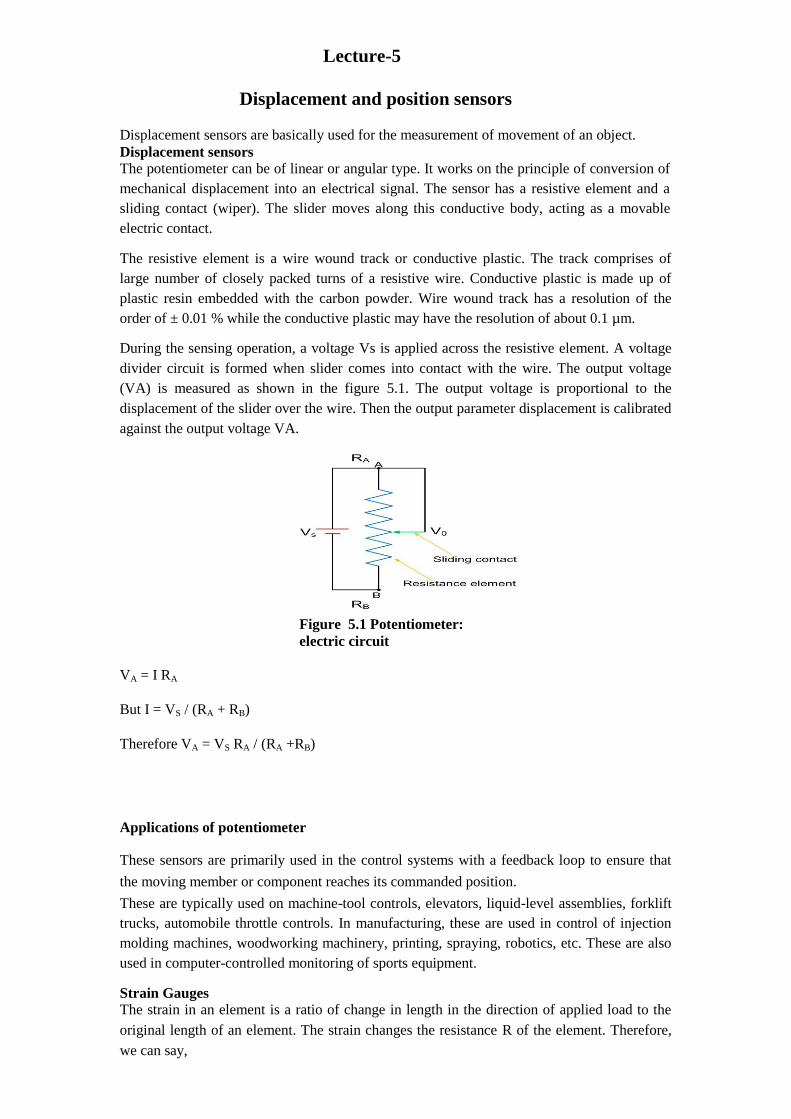
order of ± 0.01 % while the conductive plastic may have the resolution of about 0.1 µm. During the sensing operation, a voltage Vs is applied across the resistive element. A voltage
divider circuit is formed when slider comes into contact with the wire. The output voltage
(VA) is measured as shown in the figure 5.1. The output voltage is proportional to the
displacement of the slider over the wire. Then the output parameter displacement is calibrated
against the output voltage VA.
Applications of potentiometer These sensors are primarily used in the control systems with a feedback loop to ensure that
the moving member or component reaches its commanded position.
These are typically used on machine-tool controls, elevators, liquid-level assemblies, forklift
trucks, automobile throttle controls. In manufacturing, these are used in control of injection
molding machines, woodworking machinery, printing, spraying, robotics, etc. These are also
used in computer-controlled monitoring of sports equipment. Strain Gauges The strain in an element is a ratio of change in length in the direction of applied load to the
original length of an element. The strain changes the resistance R of the element. Therefore,
we can say,
Figure 5.1 Potentiometer:
electric circuit
VA = I RA
But I = VS / (RA + RB)
Therefore VA = VS RA / (RA +RB)

∆R/R α ε; ∆R/R = G ε where G is the constant of proportionality and is called as gauge factor. In general, the value
of G is considered in between 2 to 4 and the resistances are taken of the order of 100 Ω. Capacitive element based sensor
Capacitive sensor is of non-contact type sensor and is primarily used to measure the linear
displacements from few millimeters to hundreds of millimeters. It comprises of three plates,
with the upper pair forming one capacitor and the lower pair another. The linear displacement
might take in two forms:
a. one of the plates is moved by the displacement so that the plate separation changes
b. area of overlap changes due to the displacement.
The capacitance C of a parallel plate capacitor is given by,
C =rεoAε/ d where εris the relative permittivity of the dielectric between the plates, εopermittivity of free
space, A area of overlap between two plates and d the plate separation.
As the central plate moves near to top plate or bottom one due to the movement of the
element/workpiece of which displacement is to be measured, separation in between the plate
changes. This can be given as,
C1 = r (εoA) / (d + x)
C2 = r (εoA) / (d – x) When C1 and C2 are connected to a Wheatsone’s bridge, then the resulting out-of-balance
voltage would be in proportional to displacement x.
Capacitive elements can also be used as proximity sensor. The approach of the object towards
the sensor plate is used for induction of change in plate separation. This changes the
capacitance which is used to detect the object.
Linear variable differential transformer (LVDT)
Figure 5.2 Construction of a LVDT sensor

Linear variable differential transformer (LVDT) is a primary transducer used for
measurement of linear displacement with an input range of about ± 2 to ± 400 mm in
general. It has non-linearity error ± 0.25% of full range. Figure 2.2.6 shows the
construction of a LVDT sensor. It has three coils symmetrically spaced along an insulated
tube. The central coil is primary coil and the other two are secondary coils. Secondary
coils are connected in series in such a way that their outputs oppose each other. A
magnetic core attached to the element of which displacement is to be monitored is placed
inside the insulated tube.
If the magnetic core is further displaced, then the value of resultant voltage increases in
proportion with the displacement. With the help of signal processing devices such as low
pass filters and demodulators, precise displacement can be measured by using LVDT
sensors.
LVDT exhibits good repeatability and reproducibility. It is generally used as an absolute
position sensor. Since there is no contact or sliding between the constituent elements of
the sensor, it is highly reliable. These sensors are completely sealed and are widely used
in Servomechanisms, automated measurement in machine tools.
Applications of LVDT sensors
A Measurement of spool position in a wide range of servo valve applications B To provide displacement feedback for hydraulic cylinders C To control weight and thickness of medicinal products viz. tablets or pills D For automatic inspection of final dimensions of products being packed for
dispatch E To measure distance between the approaching metals during Friction welding
process F To continuously monitor fluid level as part of leak detection system G To detect the number of currency bills dispensed by an ATM

Lecture 6 Position and proximity sensors
Optical encoders
Figure 6.1 Construction and working of optical encoder
Optical encoders provide digital output as a result of linear / angular displacement. These
are widely used in the Servo motors to measure the rotation of shafts. Figure 6.1 shows
the construction of an optical encoder. It comprises of a disc with three concentric tracks
of equally spaced holes. Three light sensors are employed to detect the light passing thru
the holes. These sensors produce electric pulses which give the angular displacement of
the mechanical element e.g. shaft on which the Optical encoder is mounted. The inner
track has just one hole which is used locate the ‘home’ position of the disc. The holes on
the middle track offset from the holes of the outer track by one-half of the width of the
hole. This arrangement provides the direction of rotation to be determined. When the disc
rotates in clockwise direction, the pulses in the outer track lead those in the inner; in
counter clockwise direction they lag behind. The resolution can be determined by the
number of holes on disc. With 100 holes in one revolution, the resolution would be,
360⁰/100 = 3.6⁰.

Pneumatic Sensors
Figure 6.2 Working of Pneumatic Sensors
Pneumatic sensors are used to measure the displacement as well as to sense the proximity
of an object close to it. The displacement and proximity are transformed into change in
air pressure. Figure 6.2 shows a schematic of construction and working of such a sensor.
It comprises of three ports. Low pressure air is allowed to escape through port A. In the
absence of any obstacle / object, this low pressure air escapes and in doing so, reduces the
pressure in the port B. However when an object obstructs the low pressure air (Port A),
there is rise in pressure in output port B. This rise in pressure is calibrated to measure the
displacement or to trigger a switch. These sensors are used in robotics, pneumatics and
for tooling in CNC machine tools.
Proximity Switches
They are in a number of configurations of contact-type proximity switch being used in
manufacturing automation. These are small electrical switches which require physical
contact and a small operating force to close the contacts. They are basically employed on
conveyor systems to detect the presence of an item on the conveyor belt.

Lecture 7
Velocity, motion, force and pressure sensors
Tachogenerator
Figure 7.1 Principle of working of Techogenerator
Tachogenerator works on the principle of variable reluctance. It consists of an assembly of a
toothed wheel and a magnetic circuit as shown in figure 7.1. Toothed wheel is mounted on the
shaft or the element of which angular motion is to be measured. Magnetic circuit comprising
of a coil wound on a ferromagnetic material core. As the wheel rotates, the air gap between
wheel tooth and magnetic core changes which results in cyclic change in flux linked with the
coil. The alternating emf generated is the measure of angular motion. A pulse shaping signal
conditioner is used to transform the output into a number of pulses which can be counted by a
counter.

An alternating current (AC) generator can also be used as a techognerator. The rotor rotates in
the magnetic field produced by a stationary permanent magnet or electromagnet. During this
process, an alternating emf is produced which is the measure of the angular velocity of the
rotor. In general, these sensors exhibit nonlinearity error of about ± 0.15% and are employed
for the rotations up to about 10000 rev/min. Strain gauge based sensors work on the principle of change in electrical resistance. When, a
mechanical element subjects to a tension or a compression the electric resistance of the
material changes. This is used to measure the force acted upon the element.
Fluid pressure
Chemical, petroleum, power industry often need to monitor fluid pressure. Various types of
instruments such as diaphragms, capsules, and bellows are used to monitor the fluid pressure.
Specially designed strain gauges doped in diaphragms are generally used to measure the inlet
manifold pressure in applications such as automobiles. A typical arrangement of strain gauges
on a diaphragm is shown in figure 7.2. Application of pressurized fluid displaces the
diaphragm. This displacement is measured by the stain gauges in terms of radial and/or lateral
strains. These strain gauges are connected to form the arms of a Wheatstone bridge.
Figure 7.2 A diaphragm Tactile sensors
Figure 7.3 Schematic of a tactile sensor

In general, tactile sensors are used to sense the contact of fingertips of a robot with an object.
They are also used in manufacturing of ‘touch display’ screens of visual display units (VDUs)
of CNC machine tools. Figure 7.3 shows the construction of piezo-electric polyvinylidene
fluoride (PVDF) based tactile sensor. It has two PVDF layers separated by a soft film which
transmits the vibrations. An alternating current is applied to lower PVDF layer which
generates vibrations due to reverse piezoelectric effect. These vibrations are transmitted to the
upper PVDF layer via soft film. These vibrations cause alternating voltage across the upper
PVDF layer. When some pressure is applied on the upper PVDF layer the vibrations gets
affected and the output voltage changes. This triggers a switch or an action in robots or touch
displays.
Piezoelectric sensor Piezoelectric sensor is used for the measurement of pressure, acceleration and dynamic-forces
such as oscillation, impact, or high speed compression or tension. It contains piezoelectric
ionic crystal materials such as Quartz . On application of force or pressure these materials get
stretched or compressed. During this process, the charge over the material changes and
redistributes. One face of the material becomes positively charged and the other negatively
charged. The net charge q on the surface is proportional to the amount x by which the charges
have been displaced. The displacement is proportion to force. Therefore we can write,
q = kx = SF
where k is constant and S is a constant termed the charge sensitivity.
Liquid flow
Liquid flow is generally measured by applying the Bernoulli’s principle of fluid flow through
a constriction. The quantity of fluid flow is computed by using the pressure drop measured.
The fluid flow volume is proportional to square root of pressure difference at the two ends of
the constriction. There are various types of fluid flow measurement devices being used in
manufacturing automation such as Orifice plate, Turbine meter etc.
Turbine meter Turbine flow meter has an accuracy of ±0.3%. It has a multi blade rotor mounted centrally in
the pipe along which the flow is to be measured.. The angular velocity is proportional to the
number of pulses and fluid flow is proportional to angular velocity.

Lecture 8 Temperature and light sensors
Temperature conveys the state of a mechanical system in terms of expansion or contraction of
solids, liquids or gases, change in electrical resistance of conductors, semiconductors and
thermoelectric emfs. Temperature sensors such as bimetallic strips, thermocouples,
thermistors are widely used in monitoring of manufacturing processes such as casting,
molding, metal cutting etc. The construction details and principle of working of some of the
temperature sensors are discussed in following sections.
Bimetallic strips Bimetallic strips are used as thermal switch in controlling the temperature or heat in a
manufacturing process or system. It contains two different metal strips bonded together. The
metals have different coefficients of expansion. On heating the strips bend into curved strips
with the metal with higher coefficient of expansion on the outside of the curve. As the strips
bend, the soft iron comes in closer proximity of the small magnet and further touches. Then
the electric circuit completes and generates an alarm. In this way bimetallic strips help to
protect the desired application from heating above the pre-set value of temperature.
Resistance temperature detectors (RTDs)
RTDs work on the principle that the electric resistance of a metal changes due to change in
its temperature. On heating up metals, their resistance increases and follows a linear
relationship . The correlation is
Rt = R0 (1 + α T)
where Rt is the resistance at temperature T (⁰C) and 0Ris the temperature at 0⁰C and α is the
constant for the metal termed as temperature coefficient of resistance. The sensor is usually
made to have a resistance of 100 Ω at 0 °C
RTDs are used in the form of thin films, wire wound or coil. They are generally made of
metals such as platinum, nickel or nickel-copper alloys. Platinum wire held by a high-
temperature glass adhesive in a ceramic tube is used to measure the temperature in a metal
furnace. Other applications are: • Air conditioning and refrigeration servicing
• Food Processing
• Stoves and grills
• Textile production
• Plastics processing • Petrochemical processing
• Micro electronics
• Air, gas and liquid temperature measurement in pipes and tanks • Exhaust gas temperature measurement
Thermistors

Thermistors follow the principle of decrease in resistance with increasing temperature. The
material used in thermistor is generally a semiconductor material such as a sintered metal
oxide (mixtures of metal oxides, chromium, cobalt, iron, manganese and nickel) or doped
polycrystalline ceramic containing barium titanate (BaTiO3) and other compounds. As the
temperature of semiconductor material increases the number of electrons able to move about
increases which results in more current in the material and reduced resistance. Thermistors
are rugged and small in dimensions. They exhibit nonlinear response characteristics.
Applications of Thermistors
• To monitor the coolant temperature and/or oil temperature inside the engine • To monitor the temperature of an incubator
• Thermistors are used in modern digital thermostats
• To monitor the temperature of battery packs while charging • To monitor temperature of hot ends of 3D printers
• To maintain correct temperature in the food handling and processing industry
equipments
• To control the operations of consumer appliances such as toasters, coffee makers,
refrigerators, freezers, hair dryers, etc.
Thermocouple
Thermocouple works on the fact that when a junction of dissimilar metals heated, it produces
an electric potential related to temperature. As per Thomas Seebeck , when two wires
composed of dissimilar metals are joined at both ends and one of the ends is heated, then
there is a continuous current which flows in the thermoelectric circuit. The net open circuit
voltage (the Seebeck voltage) is a function of junction temperature and composition of two
metals.

Light sensors A light sensor is a device that is used to detect light. There are different types of light sensors
such as photocell/photoresistor and photo diodes being used in manufacturing and other
industrial applications. Photoresistor is also called as light dependent resistor (LDR). It has a resistor whose
resistance decreases with increasing incident light intensity. It is made of a high resistance
semiconductor material, cadmium sulfide (CdS). The resistance of a CdS photoresistor varies
inversely to the amount of light incident upon it. Photoresistor follows the principle of
photoconductivity which results from the generation of mobile carriers when photons are
absorbed by the semiconductor material.

Lecture 9 Signal Conditioning Devices
Signal Conditioning In previous lectures we have studied various sensors and transducers used in a mechatronics
system. Transducers sense physical phenomenon such as rise in temperature and convert the
measurand into an electrical signal viz. voltage or current. However these signals may not be
in their appropriate forms to employ them to control a mechatronics system. The signals
given by a transducer may be nonlinear in nature or may contain noise. Thus before sending
these signals to the mechatronics control unit it is essential to remove the noise, nonlinearity
associated with the raw output from a sensor or a transducer. It is also needed to modify the
amplitude (low/high) and form (analogue/digital) of the output signals into respective
acceptable limits and form which will be suitable to the control system. These activities are
carried out by using signal conditioning devices and the process is termed as ‘signal
conditioning’.
Signal conditioning system enhances the quality of signal coming from a sensor in terms
of:
1. Protection
To protect the damage to the next element of mechatronics system such
microprocessors from the high current or voltage signals.
2. Right type of signal
To convert the output signal from a transducer into the desired form i.e. voltage /
current.
3. Right level of the signal
To amplify or attenuate the signals to a right /acceptable level for the next
element.
4. Noise
To eliminate noise from a signal.
5. Manipulation
To manipulate the signal from its nonlinear form to the linear form.
Amplification Various applications of Mechatronics system such as machine tool control unit of a CNC
machine tool accept voltage amplitudes in range of 0 to 10 Volts. However many sensors
produce signals of the order of milli volts. This low level input signals from sensors must be
amplified to use them for further control action. Operational amplifiers (op-amp) are widely
used for amplification of input signals. The details are as follows.
Operational amplifier (op-amp)
Operational Amplifier is a basic and an important part of a signal conditioning system. It is
often abbreviated as op-amp. Op-amp is a high gain voltage amplifier with a differential
input. The gain is of the order of 50000 or more. Differential input is a method of transmitting
information with two different electronic signals which are generally complementary to each
other.

In general op-amp amplifies the difference between input voltages (V+ and V-). The output of
an operational amplifier can be written as
Vout = G * (V+ - V-) where G is Op-amp Gain.
Filtering
Output signals from sensors contain noise due to various external factors like improper
hardware connections, environment etc. Noise gives an error in the final output of system.
Therefore it must be removed. In practice, change in desired frequency level of output signal
is a commonly noted noise. This can be rectified by suing filters. Following types of filters
are used in practice:
1. Low Pass Filter
2. High Pass Filter
3. Band Pass Filter
4. Band Reject Filter
Low Pass Filter
Low pass filter is used to allow low frequency content and to reject high frequency content of
an input signal. Its configuration is shown in Figure 9.1
Figure 9.1 Circuitry of Low Pass Filter High Pass Filter
These types of filters allow high frequencies to pass through it and block
the lower frequencies. The figure 9.2 shows circuitry for high pass filter.
Figure 9.2 Circuitry of High Pass Filter Band Pass Filter
In some applications, we need to filter a particular band of frequencies from a wider range of
mixed signals. For this purpose, the properties of low-pass and high-pass filters circuits can
be combined to design a filter which is called as band pass filter. Band pass filter can be

developed by connecting a low-pass and a high-pass filter in series.
Data conversion devices Data Conversion Devices are very important components of a Machine Control Unit (MCU).
MCUs are controlled by various computers or microcontrollers which are accepting signals
only in Digital Form i.e. in the form of 0s and 1s, while the signals received from signal
conditioning module or sensors are generally in analogue form (continuous). Based on the signals received from sensors, MCU generates actuating signals in the Digital
form. Most of the actuators e.g. DC servo motors only accept analogue signals. Therefore the
digital signals must be converted into Analog form so that the required actuator can be
operated accordingly. For this purpose Digital to Analog Converters are used, which are
abbreviated as DACs. In subsequent sections we will be discussing about various types of
ADC and DAC devices, their principle of working and circuitry.

Lecture 10
Microprocessor
It is a multi-purpose, programmable device that reads binary instructions from a storage
device called memory, processes the data according to the instructions, and then provides
results as output. In common practice it is also known as CPU (central processing unit). CPU
can be referred as complete computational engine on a single chip. First Microcontroller,
Intel 4004 was launched in 1971. It was able to process just 4 bits. It started a new era in
electronics engineering. Microprocessor chip was one of the important inventions of the 20th
century. Table 10.1 shows the history of micro-processors.
Table 10.1 History of Micro-Processors
Name Date No. of Width of Clock Data Millions of
Transistors smallest Speed Width Instructions
wire on (In Bits) per
chip second(MIPS)
8080 1974 6000 6 2MHz 8 0.64
8088 1979 29000 3 5 MHz 16 0.33
80286 1982 134000 1.5 6MHz 16 1
80386 1985 275000 1.5 16 32 5
80486 1989 1200000 1 25 32 20
Pentium 1993 3100000 0.8 60 32 100
Pentium 1997 7500000 0.35 233 32 300
II
Pentium 1999 9500000 0.25 450 32 510
III
Pentium 4 2000 42000000 0.18 1.5 GHz 32 1700
Pentium 2004 125000000 0.09 3.6 GHz 32 7000
4P
Applications of microprocessors are classified primarily in two categories:
1. Reprogrammable Systems : Micro computers
2. Embedded Systems : photocopying machine, Digital camera
Microprocessor works or operates in binary digits i.e. 0 and 1, bits. These bits are nothing but
electrical voltages in the machine, generally 0 - low voltage level, and 1 - high voltage level.
A group of bits form a ‘word’. In general, the word length is about 8 bits. This is called as a
‘byte’. A word with a length of 4 bits is called as a ‘Nibble’
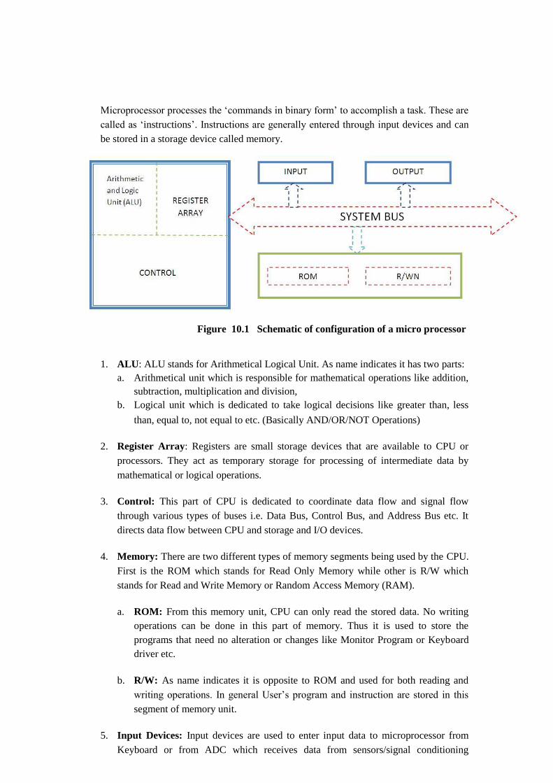
Microprocessor processes the ‘commands in binary form’ to accomplish a task. These are
called as ‘instructions’. Instructions are generally entered through input devices and can
be stored in a storage device called memory.
Figure 10.1 Schematic of configuration of a micro processor
1. ALU: ALU stands for Arithmetical Logical Unit. As name indicates it has two parts: a. Arithmetical unit which is responsible for mathematical operations like addition,
subtraction, multiplication and division, b. Logical unit which is dedicated to take logical decisions like greater than, less
than, equal to, not equal to etc. (Basically AND/OR/NOT Operations)
2. Register Array: Registers are small storage devices that are available to CPU or
processors. They act as temporary storage for processing of intermediate data by
mathematical or logical operations.
3. Control: This part of CPU is dedicated to coordinate data flow and signal flow
through various types of buses i.e. Data Bus, Control Bus, and Address Bus etc. It
directs data flow between CPU and storage and I/O devices.
4. Memory: There are two different types of memory segments being used by the CPU.
First is the ROM which stands for Read Only Memory while other is R/W which
stands for Read and Write Memory or Random Access Memory (RAM).
a. ROM: From this memory unit, CPU can only read the stored data. No writing
operations can be done in this part of memory. Thus it is used to store the
programs that need no alteration or changes like Monitor Program or Keyboard
driver etc.
b. R/W: As name indicates it is opposite to ROM and used for both reading and
writing operations. In general User’s program and instruction are stored in this
segment of memory unit.
5. Input Devices: Input devices are used to enter input data to microprocessor from
Keyboard or from ADC which receives data from sensors/signal conditioning

systems.
6. Output Devices: These devices display the results/conclusions coming out from
ALUs either in soft copy (Monitor) or in Hard Copy (Printer).
Functions of microprocessor Various functions of microprocessor are as follows:
• Microprocessor performs a variety of logical and mathematical operations using its
ALU. • It controls data flow in a system and hence can transfer data from one location to
another based on the instructions given to it.
• A microprocessor can take necessary decisions and jump to a new set of instructions
based on those decisions.
Lecture 11
Microcomputer
Microcomputer is a microprocessor based system. It is a data processing system that

employs a microprocessor as its central unit. Based on the input it takes decisions. These
decisions are further used to control a system or to actuate an action or operation. Microprocessor based programmable controller
Figure 11.1: Schematic of microcontroller. It is a microprocessor-based system. It implements the functions of a computer and a
controller on a single chip. Generally microcontroller is programmed for one specific
application and it is dedicated to a specific control function. Microcontrollers find applications in automobiles, aircraft, medical electronics and home
appliances. They are small in size and can be embedded in an electromechanical system
without taking up much space. Various types of microcontroller chips available in market are:
Motorola 68HC11, Zilog Z8 and Intel MCS51 and 96 series.
Elements of microprocessor A simple microprocessor consists of following basic elements :
• Data Bus: Through data bus, the data flow between a. various storage units b. ALU and memory units
• Address Bus: It controls the flow of memory addresses between ALU and memory
unit.
• RD (read) and WR (write) lines set or obtain the addressed locations in the memory. • Clock line transfers the clock pulse sequence to the processor. • Reset Line is used to restart execution and reset the processor to zero. • Address Latch is a register which stores the addresses in the memory. • Program Counter: It is a register which can increment its value by 1 and keeps the
record of number of instructions executed. It can be set to zero when instructed.
• Test Register: It is a register which stores intermediate or in-process data of ALU
operations. For example it is required to hold the ‘carry’ while ALU is performing
‘addition’ operation. It also stores the data which can be accessed by Instruction
decoder to make any decision. • 3-State Buffers: These are tri-state buffers. A tri-state buffer can go to a third state in
addition to the states of 1 and 0.
• The instruction register and instruction decoder are responsible for controlling the
operations of all other components of a microprocessor.
• Instruct the program counter to reset to zero. • Activate any of the six tri-state buffers (six separate lines).

• Instruct the ALU what operation to perform. • Instruct the test register to latch the ALU's test bits. • Activate the RD line. • Activate the WR line
References:
1. HMT Ltd. Mechatronics, Tata McGraw‐Hill, New Delhi, 1988.
2. Boltan, W., Mechatronics: electronic control systems in mechanical and electrical
engineering, Longman, Singapore, 1999.
3. P. N. Rao, CAD/CAM Principles and Applications, Tata McGraw Hill, 2011.
4. Mikell P.Grover,Automation,Production and Computer Intergrated
Manufacuring,PHI
5. NPTEL – Mechanical – Mechatronics and Manufacturing Automation


![MECHATRONICS BETWEEN DREAM AND ACTUAL REALITY · MECHATRONICS BETWEEN DREAM AND ACTUAL REALITY ... the pre-design and ending with de final product [16, 3]. ... The mapping errors](https://img.pdfslide.net/doc/110x75/5e72c5f1ebcea606bc60e1ac/mechatronics-between-dream-and-actual-mechatronics-between-dream-and-actual-reality.jpg)