Embed Size (px)
Citation preview
MTL 646/7 Serial Text Display Programmable Serial Interface Card
Series 2
USER MANUAL
IOD-1178, Rev. P1.55
May 27, 2011
DeltaV is a trademark of Emerson Process Management, Inc © Emerson Process Management, Inc. 1998, 1999. All rights reserved. Printed in the U.S.A. While this information is presented in good faith and believed to be accurate, MYNAH Technologies does not guarantee satisfactory results from reliance upon such information. Nothing contained herein is to be construed as a warranty or guarantee, express or implied, regarding the performance, merchantability, fitness or any other matter with respect to the products, nor as a recommendation to use any product or process in conflict with any patent. MYNAH Technologies reserves the right, without notice, to alter or improve the designs or specifications of the products described herein.
POWERFUL SOLUTIONS FOR DIGITAL PLANTS
MYNAH Technologies ▪ 504 Trade Center Blvd ▪ Chesterfield, MO 63005 ▪ Telephone (636)728-2000 ▪ Fax (636) 728-2001
www.mynah.com
1
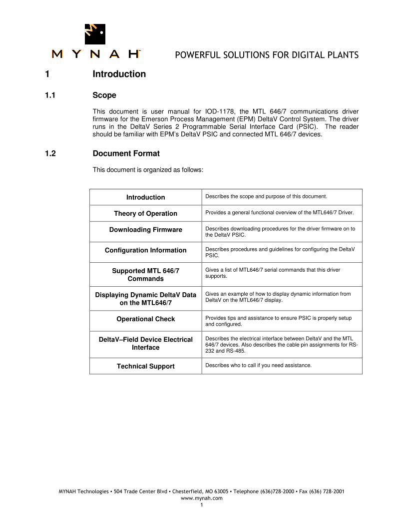
1 Introduction
1.1 Scope
This document is user manual for IOD-1178, the MTL 646/7 communications driver firmware for the Emerson Process Management (EPM) DeltaV Control System. The driver runs in the DeltaV Series 2 Programmable Serial Interface Card (PSIC). The reader should be familiar with EPM’s DeltaV PSIC and connected MTL 646/7 devices.
1.2 Document Format
This document is organized as follows:
Introduction Describes the scope and purpose of this document.
Theory of Operation Provides a general functional overview of the MTL646/7 Driver.
Downloading Firmware Describes downloading procedures for the driver firmware on to the DeltaV PSIC.
Configuration Information Describes procedures and guidelines for configuring the DeltaV PSIC.
Supported MTL 646/7 Commands
Gives a list of MTL646/7 serial commands that this driver supports.
Displaying Dynamic DeltaV Data on the MTL646/7
Gives an example of how to display dynamic information from DeltaV on the MTL646/7 display.
Operational Check Provides tips and assistance to ensure PSIC is properly setup and configured.
DeltaV–Field Device Electrical Interface
Describes the electrical interface between DeltaV and the MTL 646/7 devices. Also describes the cable pin assignments for RS-232 and RS-485.
Technical Support Describes who to call if you need assistance.
POWERFUL SOLUTIONS FOR DIGITAL PLANTS
MYNAH Technologies ▪ 504 Trade Center Blvd ▪ Chesterfield, MO 63005 ▪ Telephone (636)728-2000 ▪ Fax (636) 728-2001
www.mynah.com
2
1.3 System Specifications
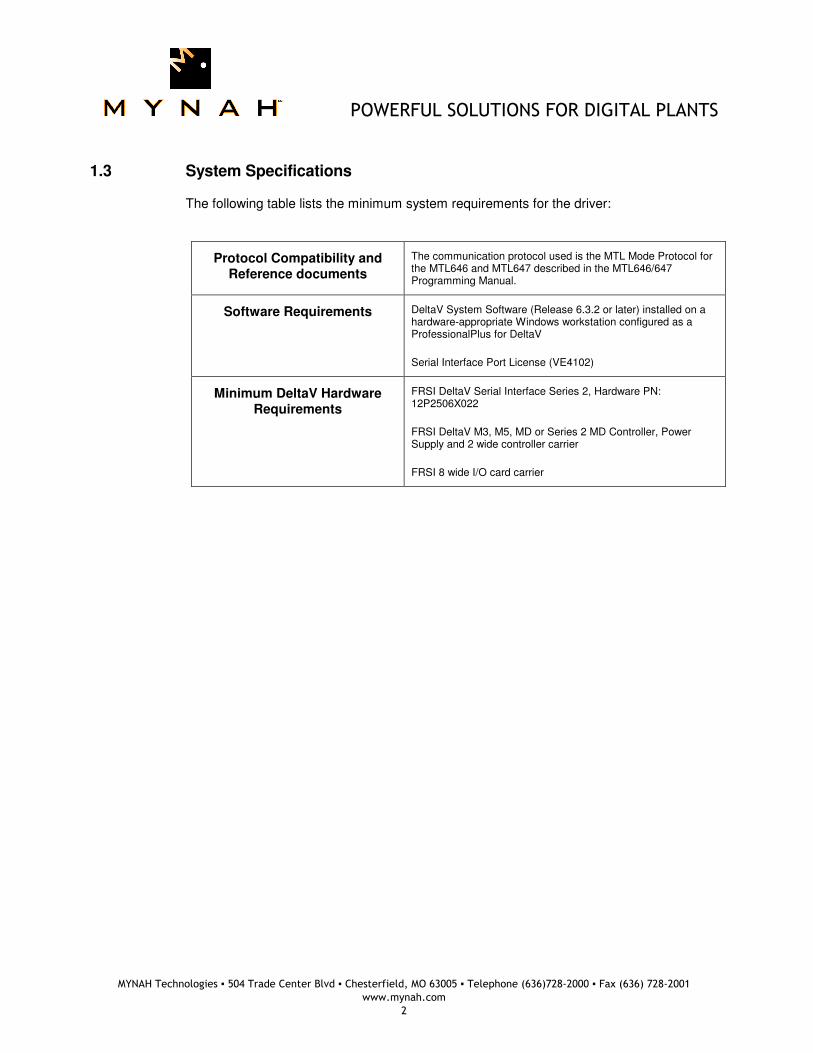
The following table lists the minimum system requirements for the driver:
Protocol Compatibility and Reference documents
The communication protocol used is the MTL Mode Protocol for the MTL646 and MTL647 described in the MTL646/647 Programming Manual.
Software Requirements DeltaV System Software (Release 6.3.2 or later) installed on a hardware-appropriate Windows workstation configured as a ProfessionalPlus for DeltaV
Serial Interface Port License (VE4102)
Minimum DeltaV Hardware Requirements
FRSI DeltaV Serial Interface Series 2, Hardware PN: 12P2506X022
FRSI DeltaV M3, M5, MD or Series 2 MD Controller, Power Supply and 2 wide controller carrier
FRSI 8 wide I/O card carrier
POWERFUL SOLUTIONS FOR DIGITAL PLANTS
MYNAH Technologies ▪ 504 Trade Center Blvd ▪ Chesterfield, MO 63005 ▪ Telephone (636)728-2000 ▪ Fax (636) 728-2001
www.mynah.com
3
2 Theory of Operation
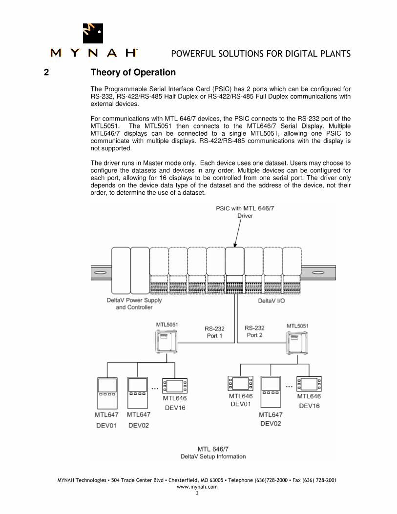
The Programmable Serial Interface Card (PSIC) has 2 ports which can be configured for RS-232, RS-422/RS-485 Half Duplex or RS-422/RS-485 Full Duplex communications with external devices. For communications with MTL 646/7 devices, the PSIC connects to the RS-232 port of the MTL5051. The MTL5051 then connects to the MTL646/7 Serial Display. Multiple MTL646/7 displays can be connected to a single MTL5051, allowing one PSIC to communicate with multiple displays. RS-422/RS-485 communications with the display is not supported. The driver runs in Master mode only. Each device uses one dataset. Users may choose to configure the datasets and devices in any order. Multiple devices can be configured for each port, allowing for 16 displays to be controlled from one serial port. The driver only depends on the device data type of the dataset and the address of the device, not their order, to determine the use of a dataset.
POWERFUL SOLUTIONS FOR DIGITAL PLANTS
MYNAH Technologies ▪ 504 Trade Center Blvd ▪ Chesterfield, MO 63005 ▪ Telephone (636)728-2000 ▪ Fax (636) 728-2001
www.mynah.com
4
3 Downloading the firmware
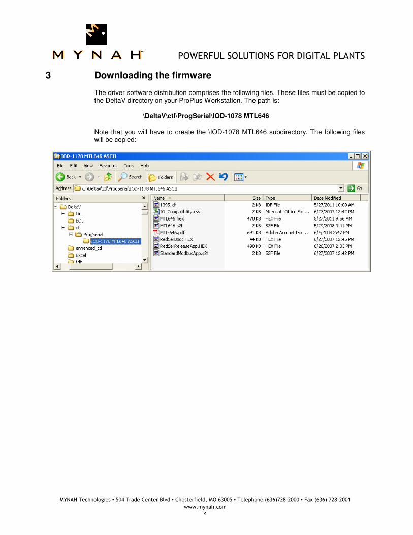
The driver software distribution comprises the following files. These files must be copied to the DeltaV directory on your ProPlus Workstation. The path is: \DeltaV\ctl\ProgSerial\IOD-1078 MTL646
Note that you will have to create the \IOD-1078 MTL646 subdirectory. The following files will be copied:
POWERFUL SOLUTIONS FOR DIGITAL PLANTS
MYNAH Technologies ▪ 504 Trade Center Blvd ▪ Chesterfield, MO 63005 ▪ Telephone (636)728-2000 ▪ Fax (636) 728-2001
www.mynah.com
5
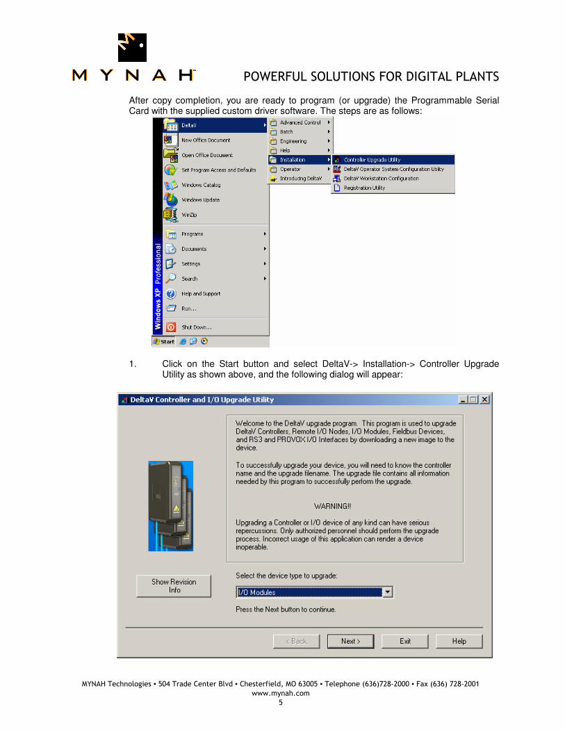
After copy completion, you are ready to program (or upgrade) the Programmable Serial Card with the supplied custom driver software. The steps are as follows:
1. Click on the Start button and select DeltaV-> Installation-> Controller Upgrade Utility as shown above, and the following dialog will appear:
POWERFUL SOLUTIONS FOR DIGITAL PLANTS
MYNAH Technologies ▪ 504 Trade Center Blvd ▪ Chesterfield, MO 63005 ▪ Telephone (636)728-2000 ▪ Fax (636) 728-2001
www.mynah.com
6
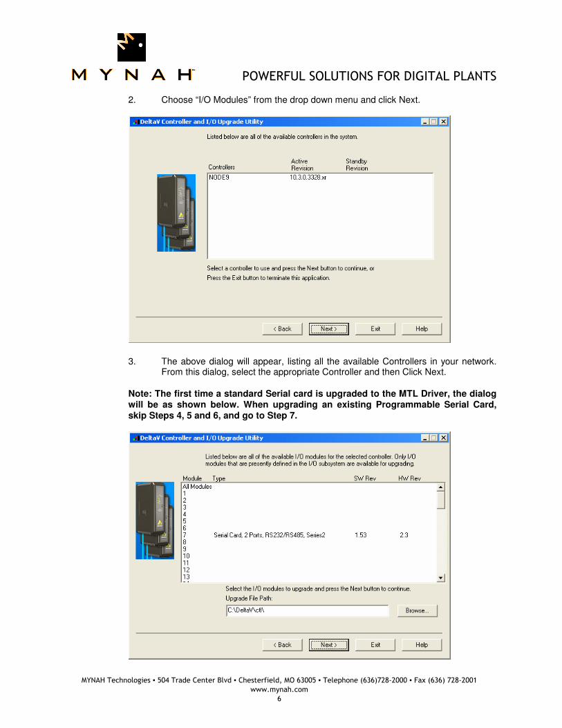
2. Choose “I/O Modules” from the drop down menu and click Next.
3. The above dialog will appear, listing all the available Controllers in your network.
From this dialog, select the appropriate Controller and then Click Next. Note: The first time a standard Serial card is upgraded to the MTL Driver, the dialog will be as shown below. When upgrading an existing Programmable Serial Card, skip Steps 4, 5 and 6, and go to Step 7.
POWERFUL SOLUTIONS FOR DIGITAL PLANTS
MYNAH Technologies ▪ 504 Trade Center Blvd ▪ Chesterfield, MO 63005 ▪ Telephone (636)728-2000 ▪ Fax (636) 728-2001
www.mynah.com
7
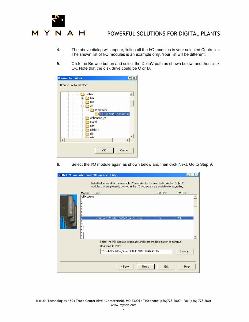
4. The above dialog will appear, listing all the I/O modules in your selected Controller.
The shown list of I/O modules is an example only. Your list will be different. 5. Click the Browse button and select the DeltaV path as shown below, and then click
Ok. Note that the disk drive could be C or D.
6. Select the I/O module again as shown below and then click Next. Go to Step 9.
POWERFUL SOLUTIONS FOR DIGITAL PLANTS
MYNAH Technologies ▪ 504 Trade Center Blvd ▪ Chesterfield, MO 63005 ▪ Telephone (636)728-2000 ▪ Fax (636) 728-2001
www.mynah.com
8
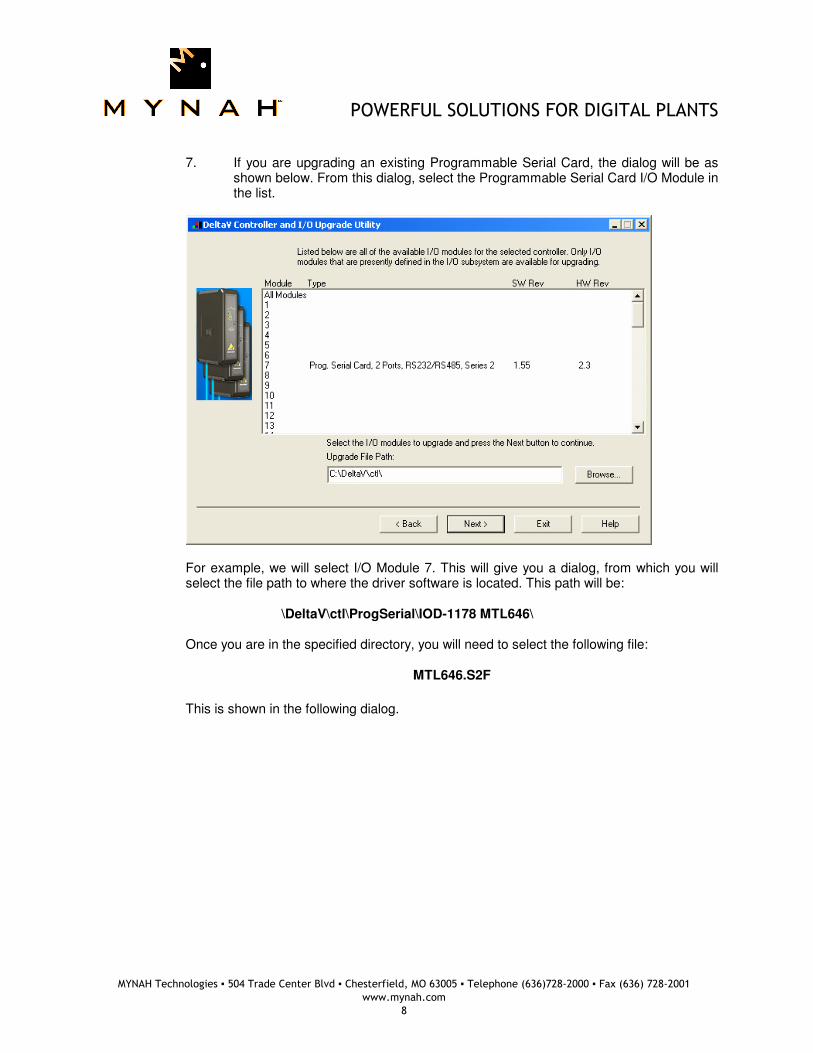
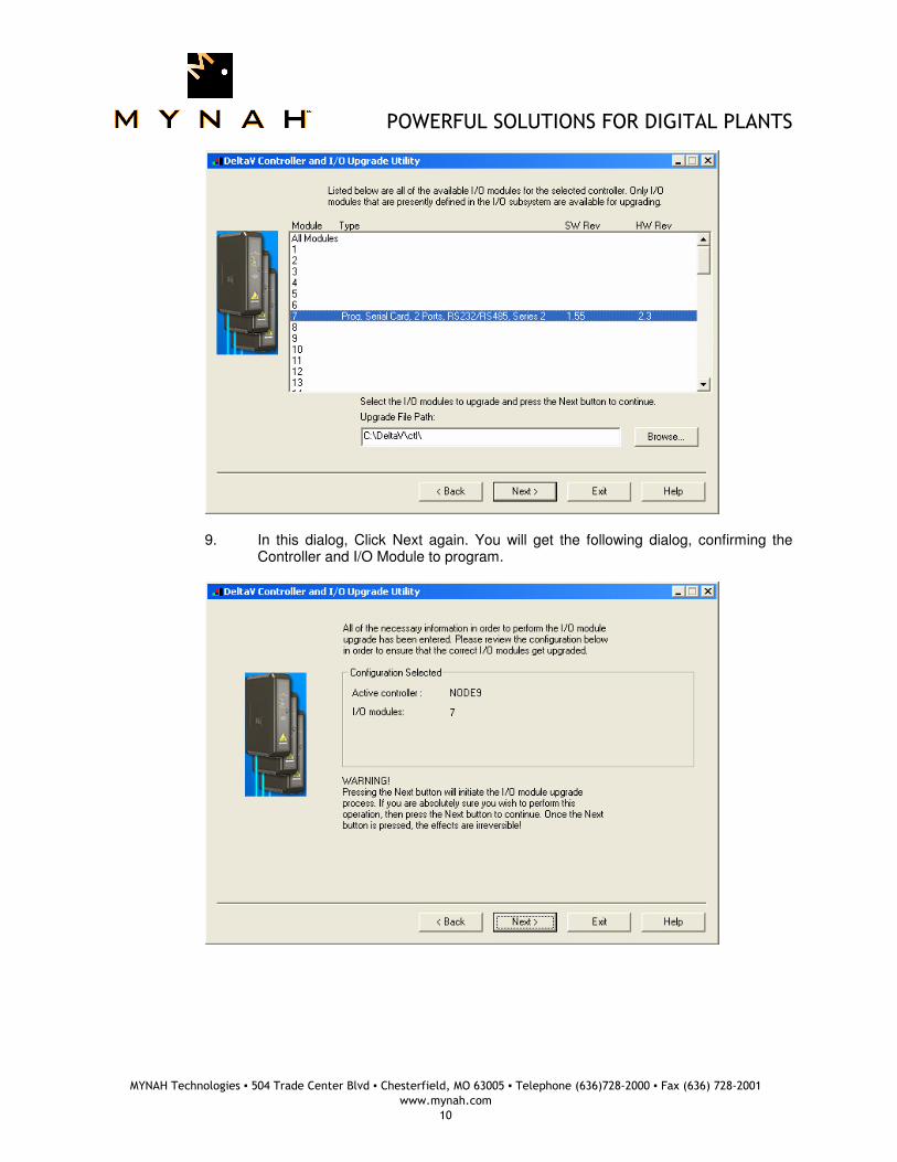
7. If you are upgrading an existing Programmable Serial Card, the dialog will be as
shown below. From this dialog, select the Programmable Serial Card I/O Module in the list.
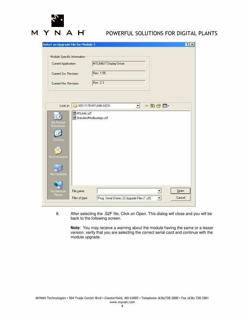
For example, we will select I/O Module 7. This will give you a dialog, from which you will select the file path to where the driver software is located. This path will be: \DeltaV\ctl\ProgSerial\IOD-1178 MTL646\ Once you are in the specified directory, you will need to select the following file:
MTL646.S2F
This is shown in the following dialog.
POWERFUL SOLUTIONS FOR DIGITAL PLANTS
MYNAH Technologies ▪ 504 Trade Center Blvd ▪ Chesterfield, MO 63005 ▪ Telephone (636)728-2000 ▪ Fax (636) 728-2001
www.mynah.com
9
8. After selecting the .S2F file, Click on Open. This dialog will close and you will be back to the following screen. Note: You may receive a warning about the module having the same or a lesser version, verify that you are selecting the correct serial card and continue with the module upgrade.
POWERFUL SOLUTIONS FOR DIGITAL PLANTS
MYNAH Technologies ▪ 504 Trade Center Blvd ▪ Chesterfield, MO 63005 ▪ Telephone (636)728-2000 ▪ Fax (636) 728-2001
www.mynah.com
10
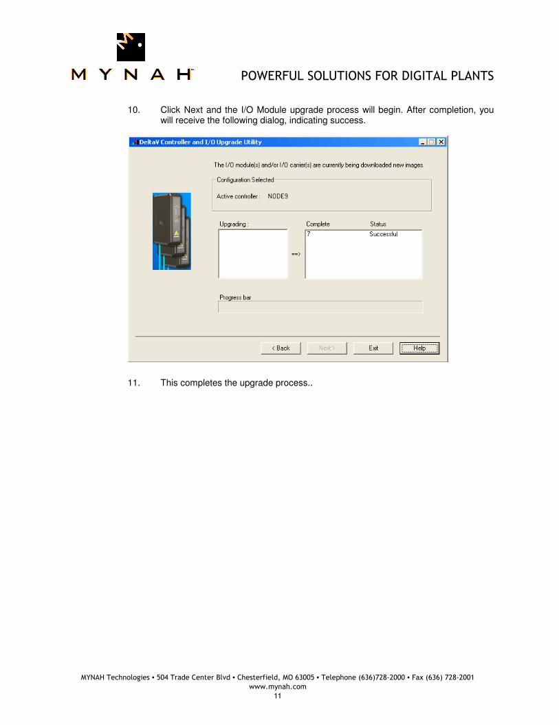
9. In this dialog, Click Next again. You will get the following dialog, confirming the
Controller and I/O Module to program.
POWERFUL SOLUTIONS FOR DIGITAL PLANTS
MYNAH Technologies ▪ 504 Trade Center Blvd ▪ Chesterfield, MO 63005 ▪ Telephone (636)728-2000 ▪ Fax (636) 728-2001
www.mynah.com
11
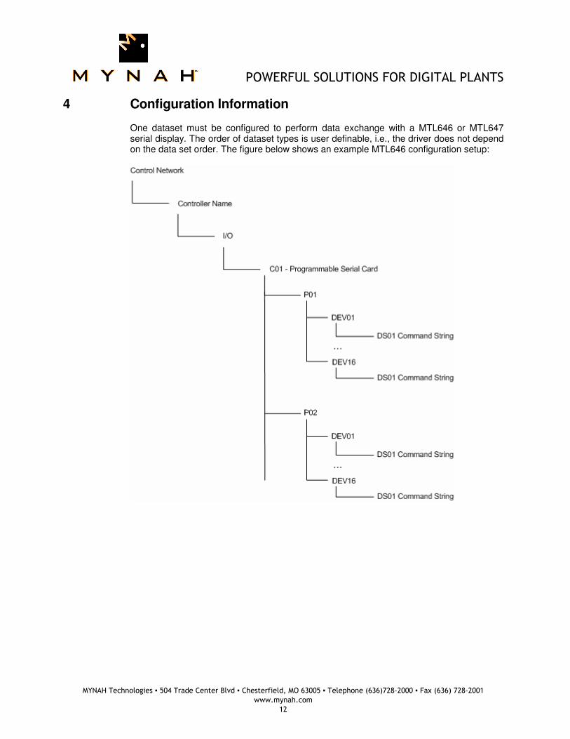
10. Click Next and the I/O Module upgrade process will begin. After completion, you
will receive the following dialog, indicating success.
11. This completes the upgrade process..
POWERFUL SOLUTIONS FOR DIGITAL PLANTS
MYNAH Technologies ▪ 504 Trade Center Blvd ▪ Chesterfield, MO 63005 ▪ Telephone (636)728-2000 ▪ Fax (636) 728-2001
www.mynah.com
12
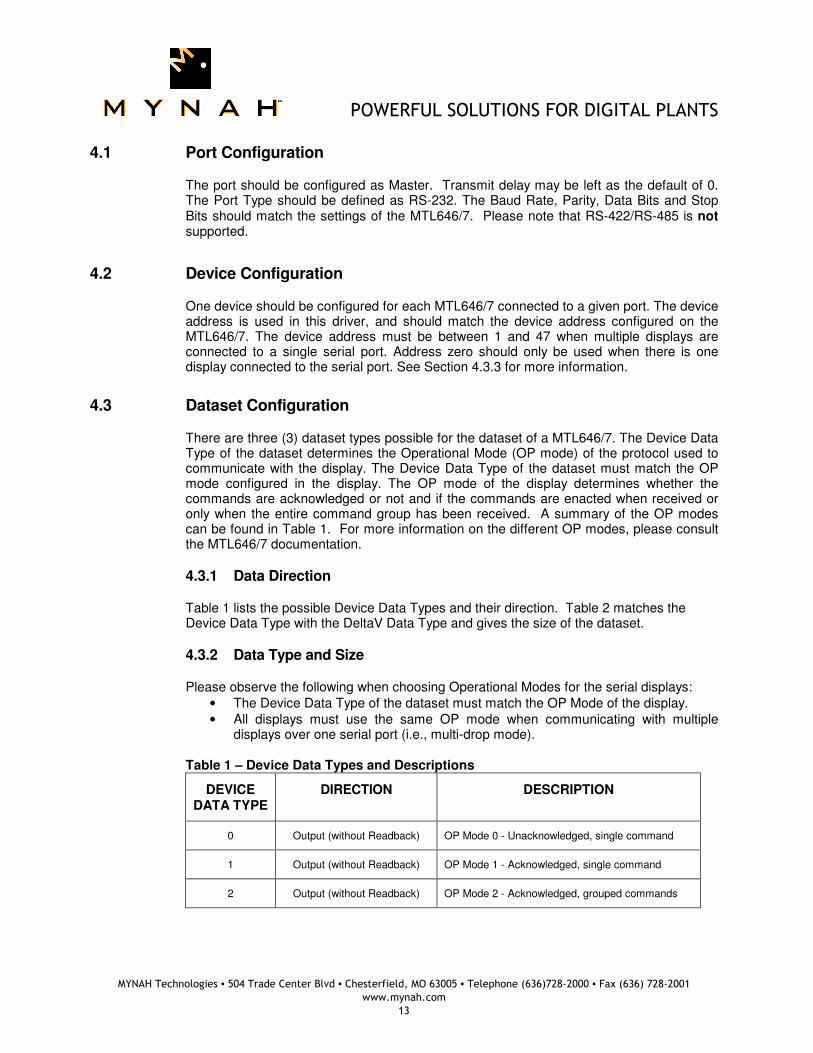
4 Configuration Information
One dataset must be configured to perform data exchange with a MTL646 or MTL647 serial display. The order of dataset types is user definable, i.e., the driver does not depend on the data set order. The figure below shows an example MTL646 configuration setup:
POWERFUL SOLUTIONS FOR DIGITAL PLANTS
MYNAH Technologies ▪ 504 Trade Center Blvd ▪ Chesterfield, MO 63005 ▪ Telephone (636)728-2000 ▪ Fax (636) 728-2001
www.mynah.com
13
4.1 Port Configuration
The port should be configured as Master. Transmit delay may be left as the default of 0. The Port Type should be defined as RS-232. The Baud Rate, Parity, Data Bits and Stop Bits should match the settings of the MTL646/7. Please note that RS-422/RS-485 is not supported.
4.2 Device Configuration
One device should be configured for each MTL646/7 connected to a given port. The device address is used in this driver, and should match the device address configured on the MTL646/7. The device address must be between 1 and 47 when multiple displays are connected to a single serial port. Address zero should only be used when there is one display connected to the serial port. See Section 4.3.3 for more information.
4.3 Dataset Configuration
There are three (3) dataset types possible for the dataset of a MTL646/7. The Device Data Type of the dataset determines the Operational Mode (OP mode) of the protocol used to communicate with the display. The Device Data Type of the dataset must match the OP mode configured in the display. The OP mode of the display determines whether the commands are acknowledged or not and if the commands are enacted when received or only when the entire command group has been received. A summary of the OP modes can be found in Table 1. For more information on the different OP modes, please consult the MTL646/7 documentation.
4.3.1 Data Direction
Table 1 lists the possible Device Data Types and their direction. Table 2 matches the Device Data Type with the DeltaV Data Type and gives the size of the dataset.
4.3.2 Data Type and Size
Please observe the following when choosing Operational Modes for the serial displays:
• The Device Data Type of the dataset must match the OP Mode of the display.
• All displays must use the same OP mode when communicating with multiple displays over one serial port (i.e., multi-drop mode).
Table 1 – Device Data Types and Descriptions
DEVICE DATA TYPE
DIRECTION DESCRIPTION
0 Output (without Readback) OP Mode 0 - Unacknowledged, single command
1 Output (without Readback) OP Mode 1 - Acknowledged, single command
2 Output (without Readback) OP Mode 2 - Acknowledged, grouped commands
POWERFUL SOLUTIONS FOR DIGITAL PLANTS
MYNAH Technologies ▪ 504 Trade Center Blvd ▪ Chesterfield, MO 63005 ▪ Telephone (636)728-2000 ▪ Fax (636) 728-2001
www.mynah.com
14
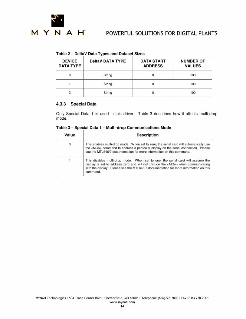
Table 2 – DeltaV Data Types and Dataset Sizes
DEVICE DATA TYPE
DeltaV DATA TYPE DATA START ADDRESS
NUMBER OF VALUES
0 String 0 100
1 String 0 100
2 String 0 100
4.3.3 Special Data
Only Special Data 1 is used in this driver. Table 3 describes how it affects multi-drop mode. Table 3 – Special Data 1 – Multi-drop Communications Mode
Value Description
0 This enables multi-drop mode. When set to zero, the serial card will automatically use the <MCn> command to address a particular display on the serial connection. Please see the MTL646/7 documentation for more information on this command.
1 This disables multi-drop mode. When set to one, the serial card will assume the display is set to address zero and will not include the <MCn> when communicating with the display. Please see the MTL646/7 documentation for more information on this command.
POWERFUL SOLUTIONS FOR DIGITAL PLANTS
MYNAH Technologies ▪ 504 Trade Center Blvd ▪ Chesterfield, MO 63005 ▪ Telephone (636)728-2000 ▪ Fax (636) 728-2001
www.mynah.com
15
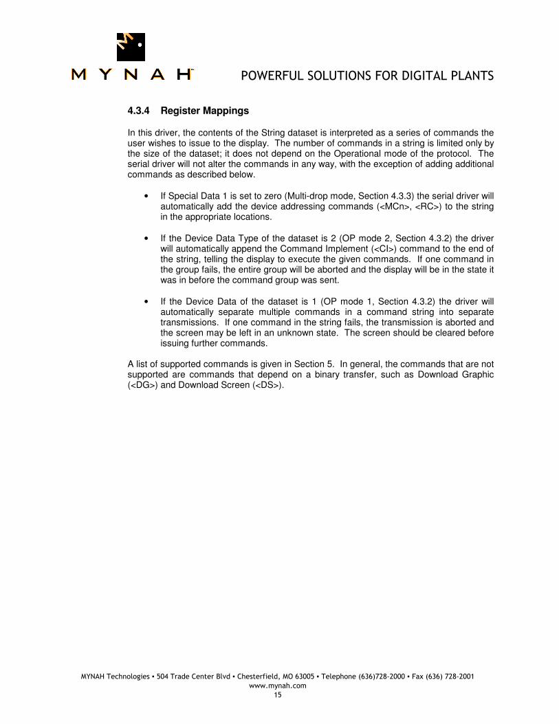
4.3.4 Register Mappings
In this driver, the contents of the String dataset is interpreted as a series of commands the user wishes to issue to the display. The number of commands in a string is limited only by the size of the dataset; it does not depend on the Operational mode of the protocol. The serial driver will not alter the commands in any way, with the exception of adding additional commands as described below.
• If Special Data 1 is set to zero (Multi-drop mode, Section 4.3.3) the serial driver will automatically add the device addressing commands (<MCn>, <RC>) to the string in the appropriate locations.
• If the Device Data Type of the dataset is 2 (OP mode 2, Section 4.3.2) the driver will automatically append the Command Implement (<CI>) command to the end of the string, telling the display to execute the given commands. If one command in the group fails, the entire group will be aborted and the display will be in the state it was in before the command group was sent.
• If the Device Data of the dataset is 1 (OP mode 1, Section 4.3.2) the driver will automatically separate multiple commands in a command string into separate transmissions. If one command in the string fails, the transmission is aborted and the screen may be left in an unknown state. The screen should be cleared before issuing further commands.
A list of supported commands is given in Section 5. In general, the commands that are not supported are commands that depend on a binary transfer, such as Download Graphic (<DG>) and Download Screen (<DS>).
POWERFUL SOLUTIONS FOR DIGITAL PLANTS
MYNAH Technologies ▪ 504 Trade Center Blvd ▪ Chesterfield, MO 63005 ▪ Telephone (636)728-2000 ▪ Fax (636) 728-2001
www.mynah.com
16
5 Supported MTL646/7 Commands
This section contains a list of supported display commands. The information provided in this section is for quick reference and is not intended to define the operation of the MTL646/7 display. For a detailed description of each command, please see the MTL646/7 documentation.
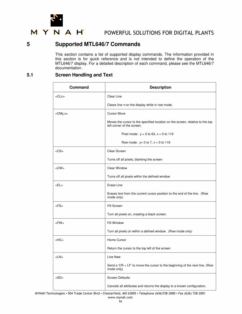
5.1 Screen Handling and Text
Command Description
<CLn> Clear Line
Clears line n on the display while in row mode.
<CMy,x> Cursor Move
Moves the cursor to the specified location on the screen, relative to the top left corner of the screen.
Pixel mode: y = 0 to 63, x = 0 to 119
Row mode: y= 0 to 7, x = 0 to 119
<CS> Clear Screen
Turns off all pixels, blanking the screen
<CW> Clear Window
Turns off all pixels within the defined window
<EL> Erase Line
Erases text from the current cursor position to the end of the line. (Row mode only)
<FS> Fill Screen
Turn all pixels on, creating a black screen.
<FW> Fill Window
Turn all pixels on within a defined window. (Row mode only)
<HC> Home Cursor
Return the cursor to the top left of the screen
<LN> Line New
Send a ‘CR + LF’ to move the cursor to the beginning of the next line. (Row mode only)
<SD> Screen Defaults
Cancels all attributes and returns the display to a known configuration.
POWERFUL SOLUTIONS FOR DIGITAL PLANTS
MYNAH Technologies ▪ 504 Trade Center Blvd ▪ Chesterfield, MO 63005 ▪ Telephone (636)728-2000 ▪ Fax (636) 728-2001
www.mynah.com
17
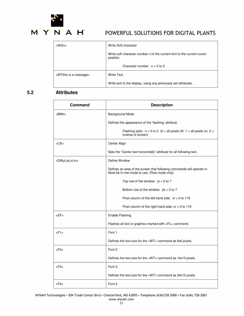
<WSn> Write Soft character
Write soft character number n of the current font to the current cursor position.
Character number: n = 0 to 3
<WTthis is a message> Write Text
Write text to the display, using any previously set attributes.
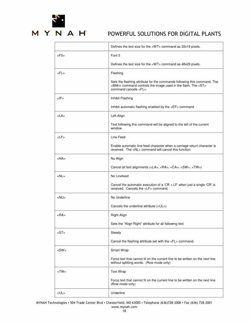
5.2 Attributes
Command Description
<BMn> Background Mode
Defines the appearance of the ‘flashing’ attribute
Flashing style: n = 0 to 2 (0 = all pixels off, 1 = all pixels on, 2 = inverse of screen)
<CA> Center Align
Sets the “Center text horizontally” attribute for all following text.
<DWyt,yb,xl,xr> Define Window
Defines an area of the screen that following commands will operate in. Must be in row mode to use. (Row mode only)
Top row of the window: yt = 0 to 7
Bottom row of the window: yb = 0 to 7
Pixel column of the left hand side: xl = 0 to 119
Pixel column of the right hand side: xr = 0 to 119
<EF> Enable Flashing
Flashes all text or graphics marked with <FL> command.
<F1> Font 1
Defines the text size for the <WT> command as 8x6 pixels.
<F2> Font 2
Defines the text size for the <WT> command as 16x10 pixels.
<F3> Font 3
Defines the text size for the <WT> command as 24x15 pixels.
<F4> Font 4
POWERFUL SOLUTIONS FOR DIGITAL PLANTS
MYNAH Technologies ▪ 504 Trade Center Blvd ▪ Chesterfield, MO 63005 ▪ Telephone (636)728-2000 ▪ Fax (636) 728-2001
www.mynah.com
18
Defines the text size for the <WT> command as 32x19 pixels.
<F5> Font 5
Defines the text size for the <WT> command as 48x29 pixels.
<FL> Flashing
Sets the flashing attribute for the commands following this command. The <BMn> command controls the image used in the flash. The <ST> command cancels <FL>.
<IF> Inhibit Flashing
Inhibit automatic flashing enabled by the <EF> command
<LA> Left Align
Text following this command will be aligned to the left of the current window.
<LF> Line Feed
Enable automatic line feed character when a carriage return character is received. The <NL> command will cancel this function.
<NA> No Align
Cancel all text alignments (<LA>, <RA>, <CA>, <SW>, <TW>)
<NL> No Linefeed
Cancel the automatic execution of a ‘CR + LF’ when just a single ‘CR’ is received. Cancels the <LF> command.
<NU> No Underline
Cancels the underline attribute (<UL>)
<RA> Right Align
Sets the “Align Right” attribute for all following text
<ST> Steady
Cancel the flashing attribute set with the <FL> command.
<SW> Smart Wrap
Force text that cannot fit on the current line to be written on the next line without splitting words. (Row mode only)
<TW> Text Wrap
Force text that cannot fit on the current line to be written on the next line (Row mode only)
<UL> Underline
POWERFUL SOLUTIONS FOR DIGITAL PLANTS
MYNAH Technologies ▪ 504 Trade Center Blvd ▪ Chesterfield, MO 63005 ▪ Telephone (636)728-2000 ▪ Fax (636) 728-2001
www.mynah.com
19
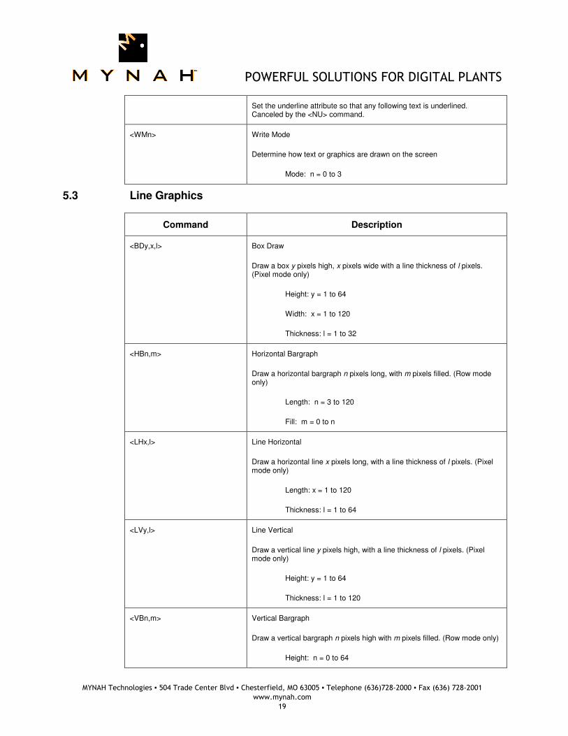
Set the underline attribute so that any following text is underlined. Canceled by the <NU> command.
<WMn> Write Mode
Determine how text or graphics are drawn on the screen
Mode: n = 0 to 3
5.3 Line Graphics
Command Description
<BDy,x,l> Box Draw
Draw a box y pixels high, x pixels wide with a line thickness of l pixels. (Pixel mode only)
Height: y = 1 to 64
Width: x = 1 to 120
Thickness: l = 1 to 32
<HBn,m> Horizontal Bargraph
Draw a horizontal bargraph n pixels long, with m pixels filled. (Row mode only)
Length: n = 3 to 120
Fill: m = 0 to n
<LHx,l> Line Horizontal
Draw a horizontal line x pixels long, with a line thickness of l pixels. (Pixel mode only)
Length: x = 1 to 120
Thickness: l = 1 to 64
<LVy,l> Line Vertical
Draw a vertical line y pixels high, with a line thickness of l pixels. (Pixel mode only)
Height: y = 1 to 64
Thickness: l = 1 to 120
<VBn,m> Vertical Bargraph
Draw a vertical bargraph n pixels high with m pixels filled. (Row mode only)
Height: n = 0 to 64
POWERFUL SOLUTIONS FOR DIGITAL PLANTS
MYNAH Technologies ▪ 504 Trade Center Blvd ▪ Chesterfield, MO 63005 ▪ Telephone (636)728-2000 ▪ Fax (636) 728-2001
www.mynah.com
20
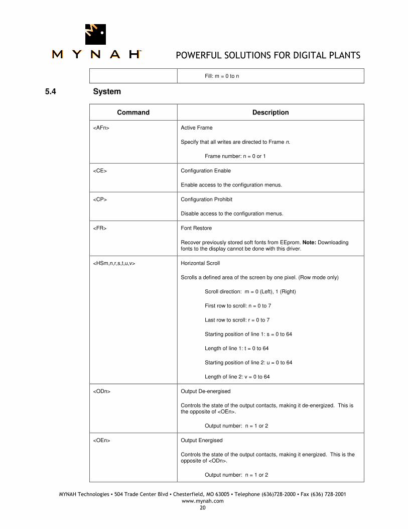
Fill: m = 0 to n
5.4 System
Command Description
<AFn> Active Frame
Specify that all writes are directed to Frame n.
Frame number: n = 0 or 1
<CE> Configuration Enable
Enable access to the configuration menus.
<CP> Configuration Prohibit
Disable access to the configuration menus.
<FR> Font Restore
Recover previously stored soft fonts from EEprom. Note: Downloading fonts to the display cannot be done with this driver.
<HSm,n,r,s,t,u,v> Horizontal Scroll
Scrolls a defined area of the screen by one pixel. (Row mode only)
Scroll direction: m = 0 (Left), 1 (Right)
First row to scroll: n = 0 to 7
Last row to scroll: r = 0 to 7
Starting position of line 1: s = 0 to 64
Length of line 1: t = 0 to 64
Starting position of line 2: u = 0 to 64
Length of line 2: v = 0 to 64
<ODn> Output De-energised
Controls the state of the output contacts, making it de-energized. This is the opposite of <OEn>.
Output number: n = 1 or 2
<OEn> Output Energised
Controls the state of the output contacts, making it energized. This is the opposite of <ODn>.
Output number: n = 1 or 2
POWERFUL SOLUTIONS FOR DIGITAL PLANTS
MYNAH Technologies ▪ 504 Trade Center Blvd ▪ Chesterfield, MO 63005 ▪ Telephone (636)728-2000 ▪ Fax (636) 728-2001
www.mynah.com
21
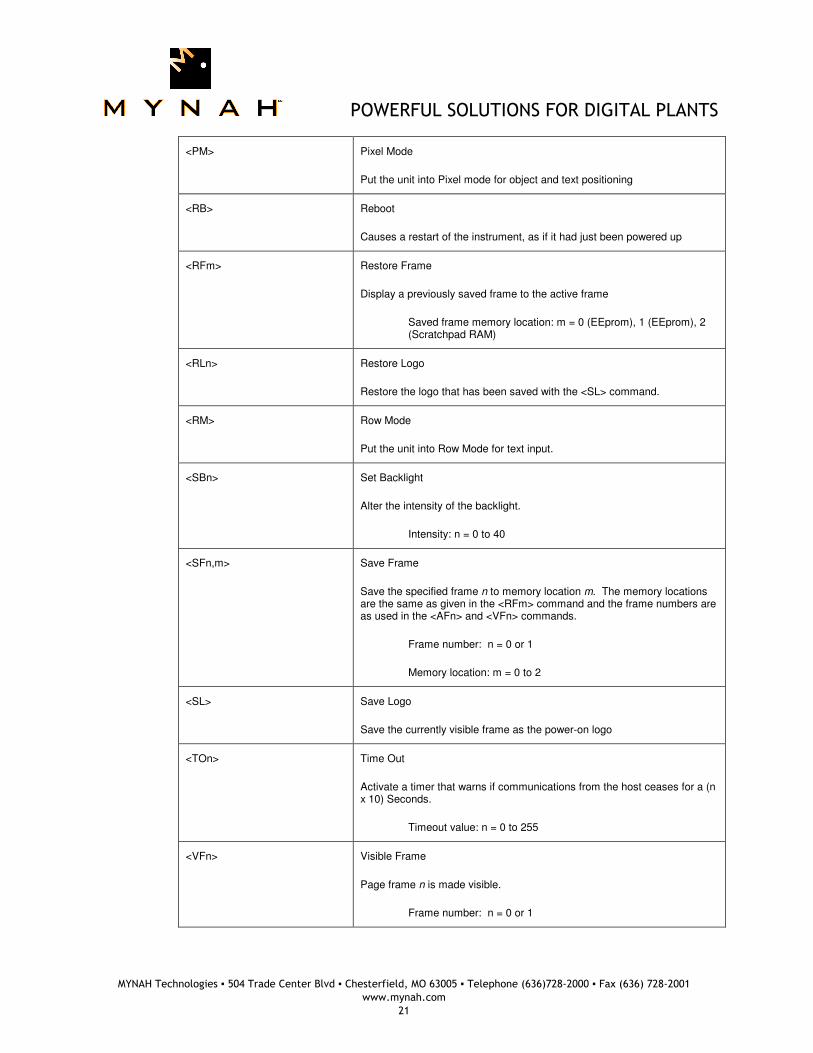
<PM> Pixel Mode
Put the unit into Pixel mode for object and text positioning
<RB> Reboot
Causes a restart of the instrument, as if it had just been powered up
<RFm> Restore Frame
Display a previously saved frame to the active frame
Saved frame memory location: m = 0 (EEprom), 1 (EEprom), 2 (Scratchpad RAM)
<RLn> Restore Logo
Restore the logo that has been saved with the <SL> command.
<RM> Row Mode
Put the unit into Row Mode for text input.
<SBn> Set Backlight
Alter the intensity of the backlight.
Intensity: n = 0 to 40
<SFn,m> Save Frame
Save the specified frame n to memory location m. The memory locations are the same as given in the <RFm> command and the frame numbers are as used in the <AFn> and <VFn> commands.
Frame number: n = 0 or 1
Memory location: m = 0 to 2
<SL> Save Logo
Save the currently visible frame as the power-on logo
<TOn> Time Out
Activate a timer that warns if communications from the host ceases for a (n x 10) Seconds.
Timeout value: n = 0 to 255
<VFn> Visible Frame
Page frame n is made visible.
Frame number: n = 0 or 1
POWERFUL SOLUTIONS FOR DIGITAL PLANTS
MYNAH Technologies ▪ 504 Trade Center Blvd ▪ Chesterfield, MO 63005 ▪ Telephone (636)728-2000 ▪ Fax (636) 728-2001
www.mynah.com
22
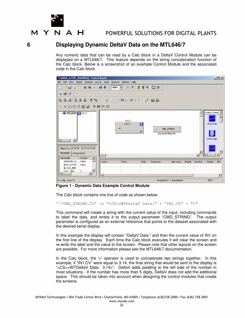
6 Displaying Dynamic DeltaV Data on the MTL646/7
Any numeric data that can be read by a Calc block in a DeltaV Control Module can be displayed on a MTL646/7. This feature depends on the string concatenation function of the Calc block. Below is a screenshot of an example Control Module and the associated code in the Calc block.
Figure 1 - Dynamic Data Example Control Module The Calc block contains one line of code as shown below: ‘^/CMD_STRING.CV’ := “<CS><WTDeltaV Data:” + ‘IN1.CV’ + “>”
This command will create a string with the current value of the input, including commands to label the data, and writes it to the output parameter “CMD_STRING”. The output parameter is configured as an external reference that points to the dataset associated with the desired serial display. In this example the display will contain “DeltaV Data:” and then the current value of IN1 on the first line of the display. Each time the Calc block executes it will clear the screen and re-write the label and the value to the screen. Please note that other layouts on the screen are possible. For more information please see the MTL646/7 documentation. In the Calc block, the ‘+’ operator is used to concatenate two strings together. In this example, if “IN1.CV” were equal to 3.14, the final string that would be sent to the display is “<CS><WTDeltaV Data: 3.14>”. DeltaV adds padding to the left side of the number in most situations. If the number has more than 5 digits, DeltaV does not add the additional space. This should be taken into account when designing the control modules that create the screens.
POWERFUL SOLUTIONS FOR DIGITAL PLANTS
MYNAH Technologies ▪ 504 Trade Center Blvd ▪ Chesterfield, MO 63005 ▪ Telephone (636)728-2000 ▪ Fax (636) 728-2001
www.mynah.com
23
7 Operational Check
7.1 Scope
The following sections provide some assistance to ensure the interface is working properly.
7.2 Verify Hardware and Software Version Number
The user can verify that the MTL646/7 driver has been installed using the DeltaV Diagnostics tool. The Diagnostics tool will show the Hardware Revision No. (HwRev) and the Software Revision No. (SwRev). To begin the DeltaV Diagnostic tool select Start-> DeltaV-> Operator-> Diagnostics. In the Diagnostics tool expand the Controller, I/O and then double click on the Programmable Serial Interface Card that has the driver installed.
The following information will be displayed: SwRev Software Revision 1.10 (or later) HwRev Hardware Revision 2.3 (or later)
7.3 Verify Configuration
• Verify port configuration: The serial port must be enabled. It must be set to Master mode. User needs to make sure communication settings such as baud rate, parity, and number of data bits matches the MTL646/7 settings.
• Verify Dataset configuration as described above.
POWERFUL SOLUTIONS FOR DIGITAL PLANTS
MYNAH Technologies ▪ 504 Trade Center Blvd ▪ Chesterfield, MO 63005 ▪ Telephone (636)728-2000 ▪ Fax (636) 728-2001
www.mynah.com
24
7.4 Verify I/O Communication with Control Studio
• User can create I/O modules in the control studio to verify correct values are read and written between the foreign device and the PSIC. For input data, the values should be changed in the foreign device and verified that the new data are correctly reported.
• To assign a Dataset and a register in the Dataset to an I/O module, follow these steps:
1. Double click the IO_IN/IO_OUT parameter for the module. This brings up the IO_IN/IO_OUT Property window.
2. Click on the Browse button. This brings up the Browse window.
3. Click on the Object_Type drop down list, select All. This displays all the Dataset tags.
4. Double click on the desired Dataset tag. This assigns the tag to the module and closes the Browse window.
5. Choose the desired register in the Parameter drop down list.
6. Click the OK button.
7.5 Using Diagnostics
• Verify PSIC communication: Select the PSIC on Diagnostics and press the right mouse button. Select Display Real -Time Statistics from the drop down menu. If the Programmable Serial Interface Card is functioning then the user will see the Valid Responses counter and the Async and/or Sync Transactions counters incrementing. There will not be any error statistics counting up.
• Verify port statistics: Select the Port on the Programmable Serial Interface Card and press the right mouse button. Then select Display Port Statistics from the drop down menu. Verify that the port communications statistics are being displayed properly and are counting as expected for the protocol’s functionality.
• Verify dataset values: Select a dataset and press the right mouse button. Select View Dataset Registers from the Drop down window. Verify that the dataset values are displayed as expected.
• Check the dataset status: Navigate down to the dataset in the left-pane and left-click on a dataset that has a bad status. The right-pane will display a Status parameter. Table 4 lists possible strings and common reasons for the error.
Table 4 - Dataset Status Strings
Status String Common Causes
No Response The serial card sent a message to the display, but did not receive a response. This could indicate a wiring issue or a miss-match of the port settings (baud rate, parity, data bits, stop bits)
Error - Bad Device Address The device was configured with an address that is outside the range of possible addresses. Examine the parent device of this dataset and verify that the address is inside the valid range. See Section 4.2.
POWERFUL SOLUTIONS FOR DIGITAL PLANTS
MYNAH Technologies ▪ 504 Trade Center Blvd ▪ Chesterfield, MO 63005 ▪ Telephone (636)728-2000 ▪ Fax (636) 728-2001
www.mynah.com
25
Error - Bad OP Mode The configured Device Data Type for this dataset is incorrect. Please see Section 4.3.2 for valid Device Data Types.
Error - Bad cmd parameters The display has received the command, but replied saying that the parameter of one of the commands, or the number of parameters, is incorrect. Please see the MTL646/7 documentation for the commands in the dataset and verify their parameters.
Error - Unrecognised Command The display has received the command string, but replied saying that one of the commands is not recognized. Check the string in the dataset for miss-typed commands. Please see the MTL646/7 documentation for the commands in the dataset and verify all the commands in the dataset exist.
Error - Device being Configured The display has received the command string, but did not to execute it because it is in program mode. Please see the MTL646/7 documentation for more information on this problem.
Error - Unknown Response The display has replied, but the reply was not recognized by the serial driver. This could indicate a miss-match in the port settings.
Error - Incorrect DeltaV Data Type This indicates that the dataset is configured for a data type other than String. Please verify the dataset configuration as given in Section 4.3.2.
Error - Reg index outside of dataset
This indicates that the command string is longer than the dataset. Verify that the number of values in the dataset is large enough for the dataset. The recommended dataset size is 100 values.
String Error - Extra '<' in string This indicates that there are too many less-than characters in the string. The less-than character is used to start a command. Verify that the command string in the dataset is valid. Please see the MTL646/7 documentation for more information on valid commands.
7.6 LED Indication
The Yellow LED for the port should be on solid when all communications on that port are valid. The Yellow LED should be blinking if there is some valid communications and some communications with errors on that port. The Yellow LED should be OFF if there are no valid communications on that port.
POWERFUL SOLUTIONS FOR DIGITAL PLANTS
MYNAH Technologies ▪ 504 Trade Center Blvd ▪ Chesterfield, MO 63005 ▪ Telephone (636)728-2000 ▪ Fax (636) 728-2001
www.mynah.com
26
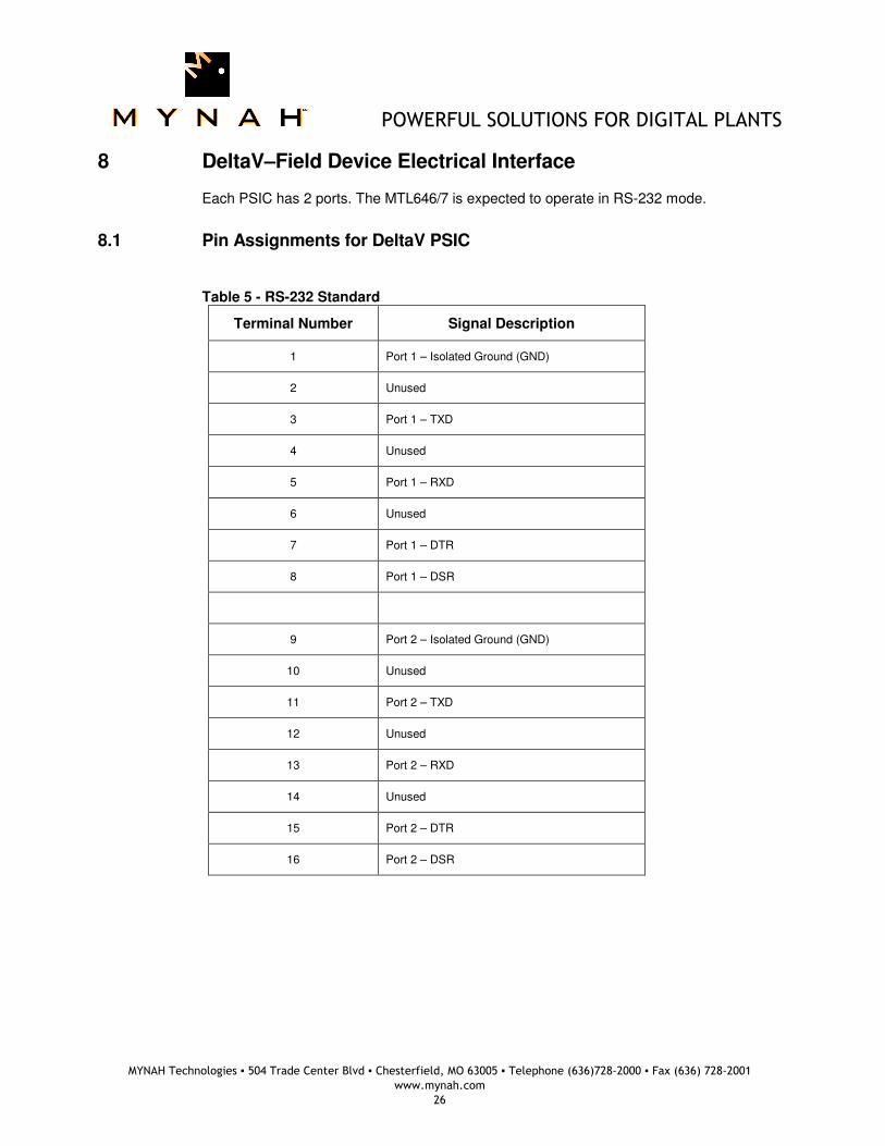
8 DeltaV–Field Device Electrical Interface
Each PSIC has 2 ports. The MTL646/7 is expected to operate in RS-232 mode.
8.1 Pin Assignments for DeltaV PSIC
Table 5 - RS-232 Standard
Terminal Number Signal Description
1 Port 1 – Isolated Ground (GND)
2 Unused
3 Port 1 – TXD
4 Unused
5 Port 1 – RXD
6 Unused
7 Port 1 – DTR
8 Port 1 – DSR
9 Port 2 – Isolated Ground (GND)
10 Unused
11 Port 2 – TXD
12 Unused
13 Port 2 – RXD
14 Unused
15 Port 2 – DTR
16 Port 2 – DSR
POWERFUL SOLUTIONS FOR DIGITAL PLANTS
MYNAH Technologies ▪ 504 Trade Center Blvd ▪ Chesterfield, MO 63005 ▪ Telephone (636)728-2000 ▪ Fax (636) 728-2001
www.mynah.com
27
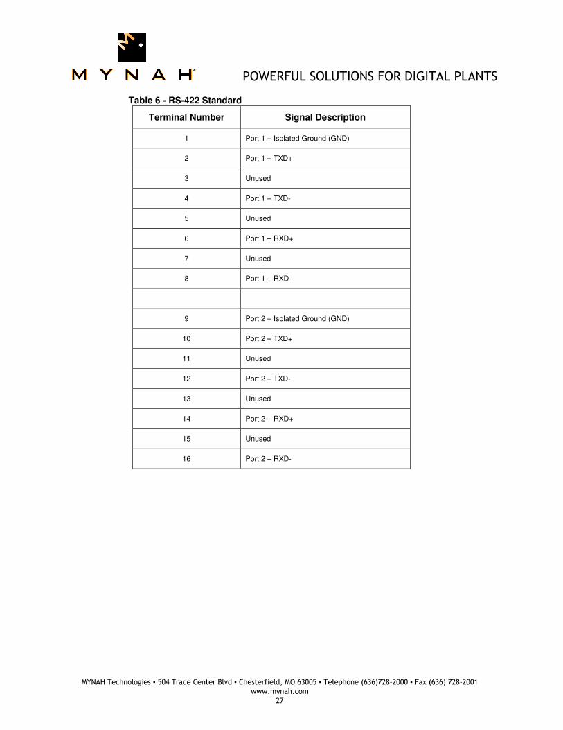
Table 6 - RS-422 Standard
Terminal Number Signal Description
1 Port 1 – Isolated Ground (GND)
2 Port 1 – TXD+
3 Unused
4 Port 1 – TXD-
5 Unused
6 Port 1 – RXD+
7 Unused
8 Port 1 – RXD-
9 Port 2 – Isolated Ground (GND)
10 Port 2 – TXD+
11 Unused
12 Port 2 – TXD-
13 Unused
14 Port 2 – RXD+
15 Unused
16 Port 2 – RXD-
POWERFUL SOLUTIONS FOR DIGITAL PLANTS
MYNAH Technologies ▪ 504 Trade Center Blvd ▪ Chesterfield, MO 63005 ▪ Telephone (636)728-2000 ▪ Fax (636) 728-2001
www.mynah.com
28
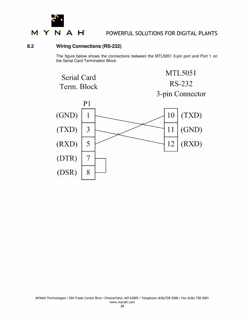
8.2 Wiring Connections (RS-232)
The figure below shows the connections between the MTL5051 3-pin port and Port 1 on the Serial Card Termination Block.
POWERFUL SOLUTIONS FOR DIGITAL PLANTS
MYNAH Technologies ▪ 504 Trade Center Blvd ▪ Chesterfield, MO 63005 ▪ Telephone (636)728-2000 ▪ Fax (636) 728-2001
www.mynah.com
29
9 Technical Support
For technical support or to report a defect, please give Mynah Technologies a call at (636) 728-2000. If a defect is discovered, please document it in as much detail as possible and then fax your report to us at (636) 728-2001. You can also send us your questions via e-mail. Our address is:
[email protected] Thank you for using DeltaV.