Embed Size (px)
Citation preview
Instruction Manual
INM4850
MTL4850HART multiplexer

ii INM4850-1Oct 2010
iiiINM4850-1Oct 2010
CONTENTS
1 INTRODUCTION . . . . . . . . . . . . . . . . . . . . . . . . . . . . . . . . . . . . . . . . . . . . . . . . . . . . . . 1
2 DESCRIPTION . . . . . . . . . . . . . . . . . . . . . . . . . . . . . . . . . . . . . . . . . . . . . . . . . . . . . . . . 12 .1 General purpose or IS? . . . . . . . . . . . . . . . . . . . . . . . . . . . . . . . . . . . . . . . . . . . . . . . . . . . . . .32 .2 Generic or custom? . . . . . . . . . . . . . . . . . . . . . . . . . . . . . . . . . . . . . . . . . . . . . . . . . . . . . . . . .32 .3 Connection methods . . . . . . . . . . . . . . . . . . . . . . . . . . . . . . . . . . . . . . . . . . . . . . . . . . . . . . . .3
3 SAFETY INFORMATION . . . . . . . . . . . . . . . . . . . . . . . . . . . . . . . . . . . . . . . . . . . . . . . . 53 .1 Precautions - General . . . . . . . . . . . . . . . . . . . . . . . . . . . . . . . . . . . . . . . . . . . . . . . . . . . . . . .5
4 INSTALLATION . . . . . . . . . . . . . . . . . . . . . . . . . . . . . . . . . . . . . . . . . . . . . . . . . . . . . . . 54 .1 HTP-SC32 HART connection unit . . . . . . . . . . . . . . . . . . . . . . . . . . . . . . . . . . . . . . . . . . . . . . . .54 .2 HMP-HM64 HART interface . . . . . . . . . . . . . . . . . . . . . . . . . . . . . . . . . . . . . . . . . . . . . . . . . . .74 .3 HCU16 HART connection unit . . . . . . . . . . . . . . . . . . . . . . . . . . . . . . . . . . . . . . . . . . . . . . . . .104 .4 HCU16AO HART connection unit . . . . . . . . . . . . . . . . . . . . . . . . . . . . . . . . . . . . . . . . . . . . . .124 .5 MTL customised backplanes . . . . . . . . . . . . . . . . . . . . . . . . . . . . . . . . . . . . . . . . . . . . . . . . . .144 .6 CPH-SC16(R) and CPH-SC32(R) backplanes . . . . . . . . . . . . . . . . . . . . . . . . . . . . . . . . . . . . . .144 .7 Backplane mounting . . . . . . . . . . . . . . . . . . . . . . . . . . . . . . . . . . . . . . . . . . . . . . . . . . . . . .164 .8 Backplanes – identification and tagging . . . . . . . . . . . . . . . . . . . . . . . . . . . . . . . . . . . . . . . .174 .9 Backplane earth rails . . . . . . . . . . . . . . . . . . . . . . . . . . . . . . . . . . . . . . . . . . . . . . . . . . . . . .174 .10 Backplanes – connections . . . . . . . . . . . . . . . . . . . . . . . . . . . . . . . . . . . . . . . . . . . . . . . . . . .184 .11 Cabling recommendations . . . . . . . . . . . . . . . . . . . . . . . . . . . . . . . . . . . . . . . . . . . . . . . . . . .204 .12 RS485 connection . . . . . . . . . . . . . . . . . . . . . . . . . . . . . . . . . . . . . . . . . . . . . . . . . . . . . . . . .20
5 MODULES . . . . . . . . . . . . . . . . . . . . . . . . . . . . . . . . . . . . . . . . . . . . . . . . . . . . . . . . . . 225 .1 MTL4850 – installation . . . . . . . . . . . . . . . . . . . . . . . . . . . . . . . . . . . . . . . . . . . . . . . . . . . . . .225 .2 Isolator modules (if used) . . . . . . . . . . . . . . . . . . . . . . . . . . . . . . . . . . . . . . . . . . . . . . . . . . .225 .3 MTL4850 module . . . . . . . . . . . . . . . . . . . . . . . . . . . . . . . . . . . . . . . . . . . . . . . . . . . . . . . . . .22
6 FAULT FINDING AND ROUTINE MAINTENANCE . . . . . . . . . . . . . . . . . . . . . . . . . . . . . . 236 .1 Maintenance precautions for MTL4500 modules . . . . . . . . . . . . . . . . . . . . . . . . . . . . . . . . . .236 .2 Fault finding on custom backplanes . . . . . . . . . . . . . . . . . . . . . . . . . . . . . . . . . . . . . . . . . . .236 .3 Routine maintenance . . . . . . . . . . . . . . . . . . . . . . . . . . . . . . . . . . . . . . . . . . . . . . . . . . . . . . .24
7 SOFTWARE CONNECTIVITY . . . . . . . . . . . . . . . . . . . . . . . . . . . . . . . . . . . . . . . . . . . . . 247 .1 Introduction . . . . . . . . . . . . . . . . . . . . . . . . . . . . . . . . . . . . . . . . . . . . . . . . . . . . . . . . . . . . . .247 .2 Communication modes . . . . . . . . . . . . . . . . . . . . . . . . . . . . . . . . . . . . . . . . . . . . . . . . . . . . .247 .3 Software setup . . . . . . . . . . . . . . . . . . . . . . . . . . . . . . . . . . . . . . . . . . . . . . . . . . . . . . . . . . .25
8 APPENDIX A - TYPICAL COMPATIBLE SYSTEMS . . . . . . . . . . . . . . . . . . . . . . . . . . . . . . 25
9 APPENDIX B - ALARM EVENT LOG . . . . . . . . . . . . . . . . . . . . . . . . . . . . . . . . . . . . . . . 26

iv INM4850-1Oct 2010
1INM4850-1Oct 2010
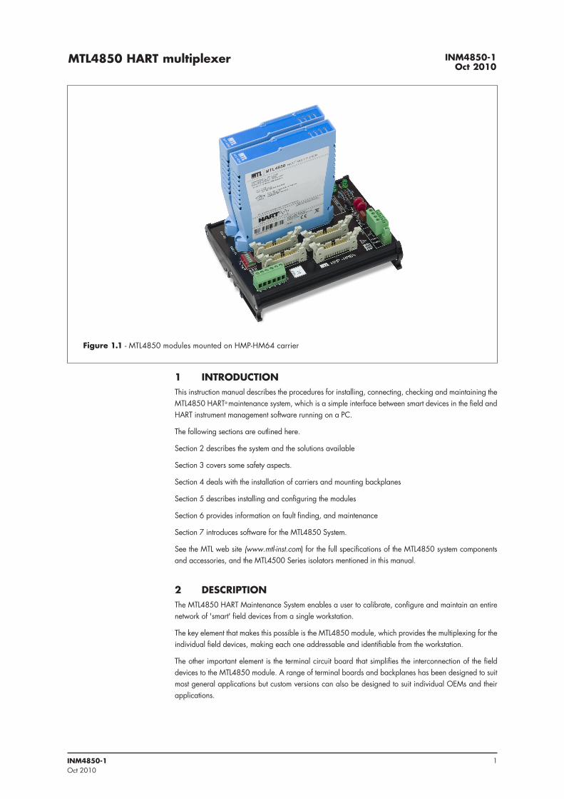
1 INTRODUCTIONThis instruction manual describes the procedures for installing, connecting, checking and maintaining the MTL4850 HART® maintenance system, which is a simple interface between smart devices in the field and HART instrument management software running on a PC.
The following sections are outlined here.
Section 2 describes the system and the solutions available
Section 3 covers some safety aspects.
Section 4 deals with the installation of carriers and mounting backplanes
Section 5 describes installing and configuring the modules
Section 6 provides information on fault finding, and maintenance
Section 7 introduces software for the MTL4850 System.
See the MTL web site (www.mtl-inst.com) for the full specifications of the MTL4850 system components and accessories, and the MTL4500 Series isolators mentioned in this manual.
2 DESCRIPTIONThe MTL4850 HART Maintenance System enables a user to calibrate, configure and maintain an entire network of 'smart' field devices from a single workstation.
The key element that makes this possible is the MTL4850 module, which provides the multiplexing for the individual field devices, making each one addressable and identifiable from the workstation.
The other important element is the terminal circuit board that simplifies the interconnection of the field devices to the MTL4850 module. A range of terminal boards and backplanes has been designed to suit most general applications but custom versions can also be designed to suit individual OEMs and their applications.
INM4850-1Oct 2010
MTL4850 HART multiplexer
Figure 1 .1 - MTL4850 modules mounted on HMP-HM64 carrier
2 INM4850-1Oct 2010
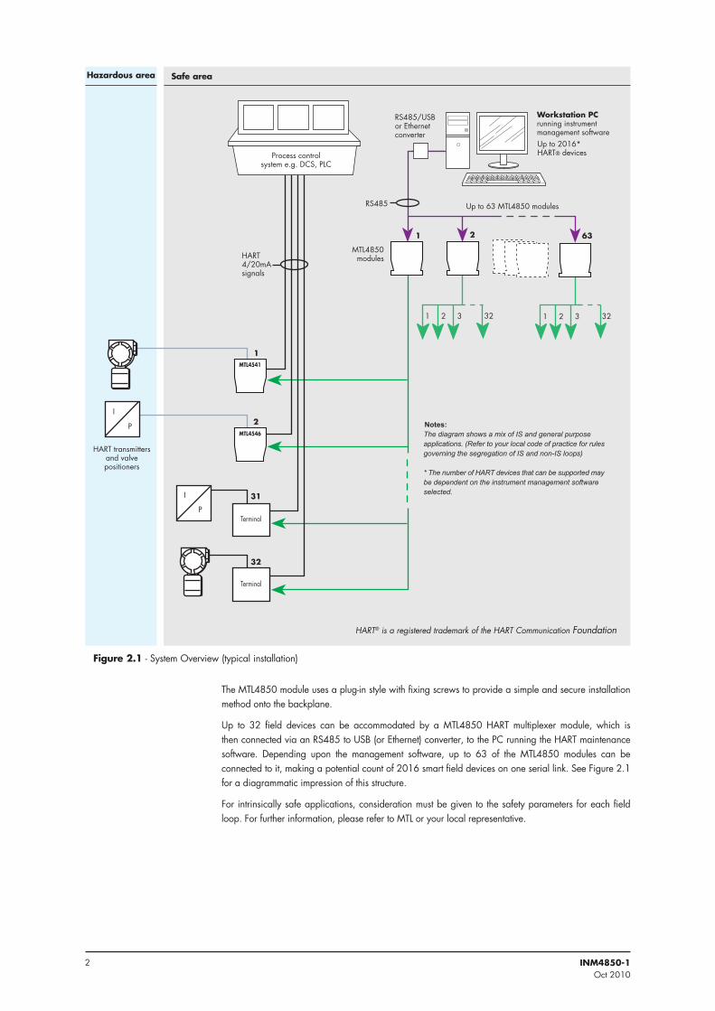
The MTL4850 module uses a plug-in style with fixing screws to provide a simple and secure installation method onto the backplane.
Up to 32 field devices can be accommodated by a MTL4850 HART multiplexer module, which is then connected via an RS485 to USB (or Ethernet) converter, to the PC running the HART maintenance software. Depending upon the management software, up to 63 of the MTL4850 modules can be connected to it, making a potential count of 2016 smart field devices on one serial link. See Figure 2.1 for a diagrammatic impression of this structure.
For intrinsically safe applications, consideration must be given to the safety parameters for each field loop. For further information, please refer to MTL or your local representative.
HART® is a registered trademark of the HART Communication Foundation
Safe areaHazardous area
Figure 2 .1 - System Overview (typical installation)
�������������������������������������
� � ��
������������
� ���
�����������������
���������������������������������������������������
�����
�
��
�
��
��
��������
�
�
����������������������� � �������
����������������������
�������� ���������������
��������
� � ��
�� ����
�� ����
�����������������������������
���������������������������������������������� ����������� ���������������������� �� �������������������� ������������������������������������������� �����
����������������������������������������������������������������������������������������������� ����
3INM4850-1Oct 2010
2 .1 General purpose or IS?The MTL HART Management System can be used to control and maintain field devices that are located in a safe area or a hazardous areas.
For safe areas, HART Connection Units provide the necessary terminals to connect up to 32 field devices. These may be basic connection units, linked to a HART interface board, or they may be integrated units with an MTL4850 multiplexer onboard. Section 2.3 explains this in more detail.
Hazardous-area field devices can be handled using IS isolating interfaces conveniently mounted on a backplane with facilities for onward connection to the host. Here also there is a choice of a backplane with an onboard MTL4850 multiplexer (CPH models), or legacy backplanes that can be linked to a HART interface board that carries the MTL4850 multipexer(s).
Having the isolators mounted on a backplane dramatically reduces the amount of hand wiring required and therefore reduces the number of potential wiring errors. The hazardous-area wiring terminates on the isolating modules, not the backplane, consequently the backplanes do not need IS certification.
2 .2 Generic or custom?A range of generic connection units is available for both input and output field-device wiring. These are not designed for any particular DCS type and may be used universally.
The alternative is to choose a connection unit or backplane that integrates with the type of DCS being used on the plant. The key advantage of this method is the use of a DCS’s specific connector type, which simplifies the wiring of the connection units into the system. Various solutions are available to suit individual DCS types and a listing of the currently available connection units and backplanes is given in Appendix A.
2 .3 Connection methodsThere are currently three methods for linking the HART signals to the MTL4850:
a) using an integrated connection unit – HTP-SC32 - see Figure 2.2
b) via a connection unit to a HART interface (HMP-HM64) - see Figure 2.3
c) using an IS isolator backplane with a HART interface - see Figure 2.4
Note: the MTL4850 may also be used to update existing HART installations, but these methods are not discussed here. Consult MTL for information if this is of interest.
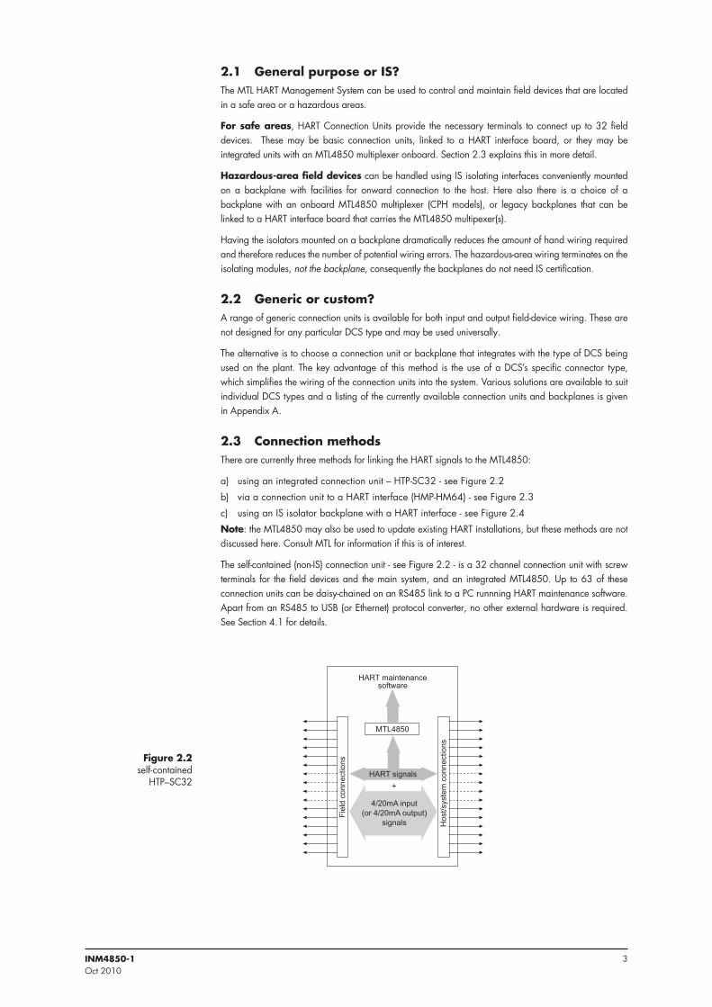
The self-contained (non-IS) connection unit - see Figure 2.2 - is a 32 channel connection unit with screw terminals for the field devices and the main system, and an integrated MTL4850. Up to 63 of these connection units can be daisy-chained on an RS485 link to a PC runnning HART maintenance software. Apart from an RS485 to USB (or Ethernet) protocol converter, no other external hardware is required. See Section 4.1 for details.
���������
��������
���
�����
���
����
��������
������� ����
��������������������������
�� ����
������������������������
�
������
Figure 2 .2 self-contained
HTP–SC32
4 INM4850-1Oct 2010
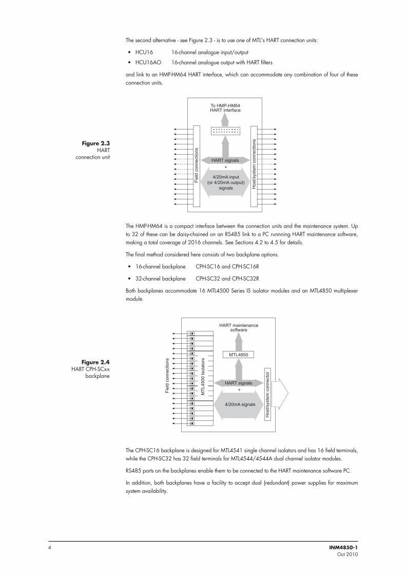
The second alternative - see Figure 2.3 - is to use one of MTL's HART connection units:
• HCU16 16-channel analogue input/output
• HCU16AO 16-channel analogue output with HART filters
and link to an HMP-HM64 HART interface, which can accommodate any combination of four of these connection units.
The HMP-HM64 is a compact interface between the connection units and the maintenance system. Up to 32 of these can be daisy-chained on an RS485 link to a PC runnning HART maintenance software, making a total coverage of 2016 channels. See Sections 4.2 to 4.5 for details.
The final method considered here consists of two backplane options.
• 16-channel backplane CPH-SC16 and CPH-SC16R
• 32-channel backplane CPH-SC32 and CPH-SC32R
Both backplanes accommodate 16 MTL4500 Series IS isolator modules and an MTL4850 multiplexer module.
The CPH-SC16 backplane is designed for MTL4541 single channel isolators and has 16 field terminals, while the CPH-SC32 has 32 field terminals for MTL4544/4544A dual channel isolator modules.
RS485 ports on the backplanes enable them to be connected to the HART maintenance software PC.
In addition, both backplanes have a facility to accept dual (redundant) power supplies for maximum system availability.
���������
��������
���
�����
���
����
������
�
� ��
�
������
���
��� ��������������������
� ���
��� ��������
�������������
Figure 2 .4 HART CPH-SCxx
backplane
���������
��������
���
�����
���
����
��������
������� ����
��������������������������
�� ����
�������������������������
�
Figure 2 .3 HART
connection unit
5INM4850-1Oct 2010
3 SAFETY INFORMATION Before beginning the installation of any of this equipment it is IMPORTANT that the information in this section is read and understood.
3 .1 Precautions - GeneralUnits MUST NOT be installed in a hazardous area unless certified and marked for this purpose or unless protected by a locally accepted explosion-proof technique .
• Make sure all installation work is carried out in accordance with local standards, codes of practice, and site regulations.
• Check that the hazardous-area equipment complies with the descriptive system document.
• If in doubt, refer to the certificate/catalogue for clarification of any aspects of intrinsic safety or contact MTL, or your local representative, for assistance.
• Check that the interface unit(s) functions(s) are correct for the application.
4 INSTALLATIONThis section details the methods used to implement the connection options outlined in Section 2.3.
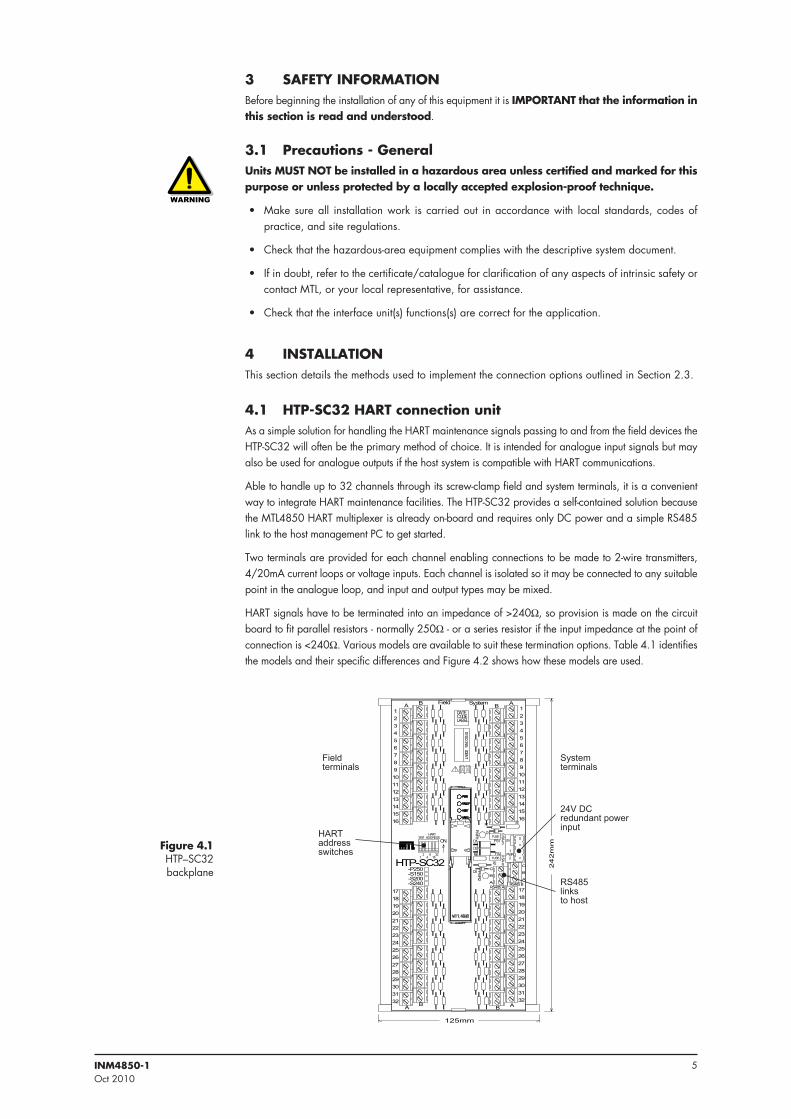
4 .1 HTP-SC32 HART connection unitAs a simple solution for handling the HART maintenance signals passing to and from the field devices the HTP-SC32 will often be the primary method of choice. It is intended for analogue input signals but may also be used for analogue outputs if the host system is compatible with HART communications.
Able to handle up to 32 channels through its screw-clamp field and system terminals, it is a convenient way to integrate HART maintenance facilities. The HTP-SC32 provides a self-contained solution because the MTL4850 HART multiplexer is already on-board and requires only DC power and a simple RS485 link to the host management PC to get started.
Two terminals are provided for each channel enabling connections to be made to 2-wire transmitters, 4/20mA current loops or voltage inputs. Each channel is isolated so it may be connected to any suitable point in the analogue loop, and input and output types may be mixed.
HART signals have to be terminated into an impedance of >240W, so provision is made on the circuit board to fit parallel resistors - normally 250W - or a series resistor if the input impedance at the point of connection is <240W. Various models are available to suit these termination options. Table 4.1 identifies the models and their specific differences and Figure 4.2 shows how these models are used.
Figure 4 .1 HTP–SC32 backplane
�����������
����
�
�����
����� ��
����������
� � ��� � ��
��� ����
����
��� �������
����������
�
�
� ����
�
�
�
�
�
�
�
�
��
��
��
��
��
��
����
�
�
�
�
�
�
�
�
�
��
��
��
��
��
��
��
� �
��
��
��
��
��
��
��
��
��
��
��
��
��
��
��
��
��
��
��
��
��
��
��
��
��
��
��
��
��
��
��
��
��������������������
�� �
���
�
�
������
������
�
� ������
������
�
�
�
�
����
���
�
�
�� � ��������������������
����������������
���������������
��������������
������������������
6 INM4850-1Oct 2010
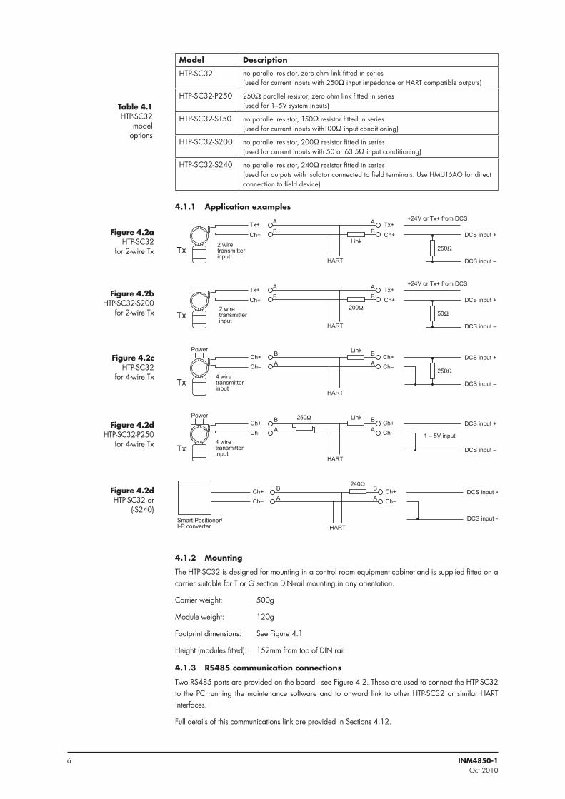
Model Description
HTP-SC32 no parallel resistor, zero ohm link fitted in series (used for current inputs with 250W input impedance or HART compatible outputs)
HTP-SC32-P250 250W parallel resistor, zero ohm link fitted in series(used for 1–5V system inputs)
HTP-SC32-S150 no parallel resistor, 150W resistor fitted in series(used for current inputs with100W input conditioning)
HTP-SC32-S200 no parallel resistor, 200W resistor fitted in series(used for current inputs with 50 or 63.5W input conditioning)
HTP-SC32-S240 no parallel resistor, 240W resistor fitted in series(used for outputs with isolator connected to field terminals. Use HMU16AO for direct connection to field device)
4 .1 .1 Application examples
Table 4 .1 HTP-SC32
model options
�
������������
�����������
�������� ����������
���������������������
�
� ��
���
���
��
�������
����
Figure 4 .2a HTP-SC32
for 2-wire Tx
�
������������
�����������
�������� ����������
���������������������
�
� ��
���
���
��
���
�������
Figure 4 .2b HTP-SC32-S200
for 2-wire Tx
�����������
����������������������� �����������
�
���
���
����
����
����
���
���
�����
Figure 4 .2c HTP-SC32
for 4-wire Tx
�����������
����������������������� �����������
�
���
������� ����
����
���
���
�����
������������
Figure 4 .2d HTP-SC32-P250
for 4-wire Tx
�����������
��������������������������� �����������
�
�
����
�������
����
����
���
Figure 4 .2d HTP-SC32 or
(-S240)
4 .1 .2 Mounting
The HTP-SC32 is designed for mounting in a control room equipment cabinet and is supplied fitted on a carrier suitable for T or G section DIN-rail mounting in any orientation.
Carrier weight: 500g
Module weight: 120g
Footprint dimensions: See Figure 4.1
Height (modules fitted): 152mm from top of DIN rail
4 .1 .3 RS485 communication connections
Two RS485 ports are provided on the board - see Figure 4.2. These are used to connect the HTP-SC32 to the PC running the maintenance software and to onward link to other HTP-SC32 or similar HART interfaces.
Full details of this communications link are provided in Sections 4.12.
7INM4850-1Oct 2010
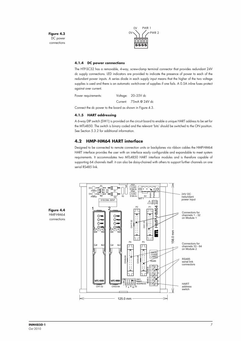
4 .1 .4 DC power connections
The HTP-SC32 has a removable, 4-way, screw-clamp terminal connector that provides redundant 24V dc supply connections. LED indicators are provided to indicate the presence of power to each of the redundant power inputs. A series diode in each supply input means that the higher of the two voltage supplies is used and there is an automatic switch-over of supplies if one fails. A 0.5A inline fuses protect against over current.
Power requirements: Voltage: 20–35V dc
Current: 75mA @ 24V dc
Connect the dc power to the board as shown in Figure 4.3.
4 .1 .5 HART addressing
A 6-way DIP switch (SW1) is provided on the circuit board to enable a unique HART address to be set for the MTL4850. The switch is binary coded and the relevant ‘bits’ should be switched to the ON position. See Section 5.3.2 for additional information.
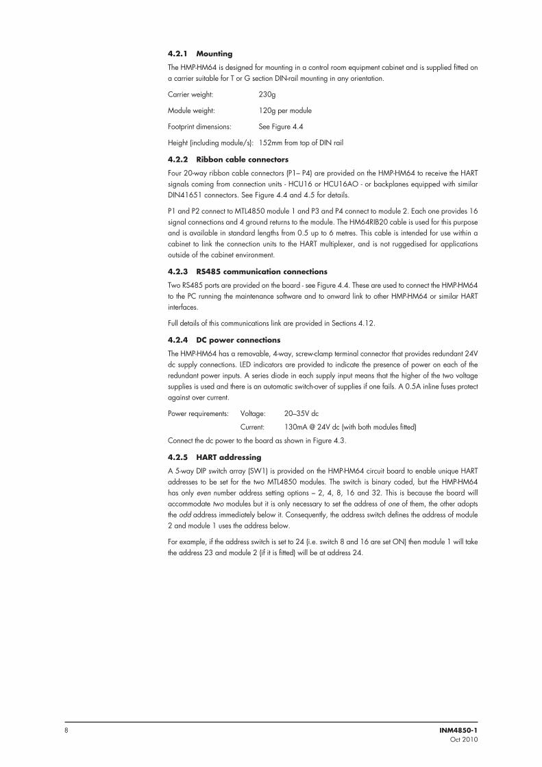
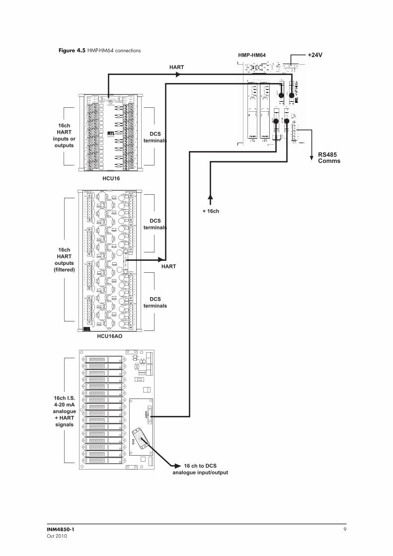
4 .2 HMP-HM64 HART interfaceDesigned to be connected to remote connection units or backplanes via ribbon cables the HMP-HM64 HART interface provides the user with an interface easily configurable and expandable to meet system requirements. It accommodates two MTL4850 HART interface modules and is therefore capable of supporting 64 channels itself: it can also be daisy-chained with others to support further channels on one serial RS485 link.
�������
�������Figure 4 .3DC power
connections
��
��������������
����������������
��
����
��
����
��
�����
���
� �����
� ��
��
��
�� �
��
�
��
�����
�����
������ �������
����
��
����
���
����
���
����
���
���
���
�����������
���
���
�
�������������
�������������
��
��
���
�������
� �
� �
��
��
�
�����
�
� �
����
���
����
���
��
���� ������������ ����������������� ��
���� ������������ ������������������ ��
������� ���������� �������
������ ������������ ����
�������� �������
Figure 4 .4HMP-HM64connections
8 INM4850-1Oct 2010
4 .2 .1 Mounting
The HMP-HM64 is designed for mounting in a control room equipment cabinet and is supplied fitted on a carrier suitable for T or G section DIN-rail mounting in any orientation.
Carrier weight: 230g
Module weight: 120g per module
Footprint dimensions: See Figure 4.4
Height (including module/s): 152mm from top of DIN rail
4 .2 .2 Ribbon cable connectors
Four 20-way ribbon cable connectors (P1– P4) are provided on the HMP-HM64 to receive the HART signals coming from connection units - HCU16 or HCU16AO - or backplanes equipped with similar DIN41651 connectors. See Figure 4.4 and 4.5 for details.
P1 and P2 connect to MTL4850 module 1 and P3 and P4 connect to module 2. Each one provides 16 signal connections and 4 ground returns to the module. The HM64RIB20 cable is used for this purpose and is available in standard lengths from 0.5 up to 6 metres. This cable is intended for use within a cabinet to link the connection units to the HART multiplexer, and is not ruggedised for applications outside of the cabinet environment.
4 .2 .3 RS485 communication connections
Two RS485 ports are provided on the board - see Figure 4.4. These are used to connect the HMP-HM64 to the PC running the maintenance software and to onward link to other HMP-HM64 or similar HART interfaces.
Full details of this communications link are provided in Sections 4.12.
4 .2 .4 DC power connections
The HMP-HM64 has a removable, 4-way, screw-clamp terminal connector that provides redundant 24V dc supply connections. LED indicators are provided to indicate the presence of power on each of the redundant power inputs. A series diode in each supply input means that the higher of the two voltage supplies is used and there is an automatic switch-over of supplies if one fails. A 0.5A inline fuses protect against over current.
Power requirements: Voltage: 20–35V dc
Current: 130mA @ 24V dc (with both modules fitted)
Connect the dc power to the board as shown in Figure 4.3.
4 .2 .5 HART addressing
A 5-way DIP switch array (SW1) is provided on the HMP-HM64 circuit board to enable unique HART addresses to be set for the two MTL4850 modules. The switch is binary coded, but the HMP-HM64 has only even number address setting options – 2, 4, 8, 16 and 32. This is because the board will accommodate two modules but it is only necessary to set the address of one of them, the other adopts the odd address immediately below it. Consequently, the address switch defines the address of module 2 and module 1 uses the address below.
For example, if the address switch is set to 24 (i.e. switch 8 and 16 are set ON) then module 1 will take the address 23 and module 2 (if it is fitted) will be at address 24.
9INM4850-1Oct 2010
����
����������
����� ����������
���������
������
� ��
���
����
���
� ��
��
���
� ��� ��
��
���
�����
��
��
��
�
�
�
�
�
��
��
��
��
�
�
�
�
��
��
��
�
�
�
�
�
��
��
��
��
�
�
�
�
�������
�����������
�������
��������������
���
���
������������
������������
������������
���������������������������
���
���
������ � ������������������ �������
������
�
�
�
�
�
�
�
�
���
�
�
�
�
�
�
�
�
���
�
�
�
�
�
�
�
�
���
�
�
�
�
�
�
�
�
���
����� ������
�
�
�
�
�
�
�
�
�
�
�
�
�
�
�
�
�
�
�
�
�
�
�
�
���
���
���
�
�
�
�
�
�
�
���
�
�������
�����
�������Figure 4 .5 HMP-HM64 connections
10 INM4850-1Oct 2010
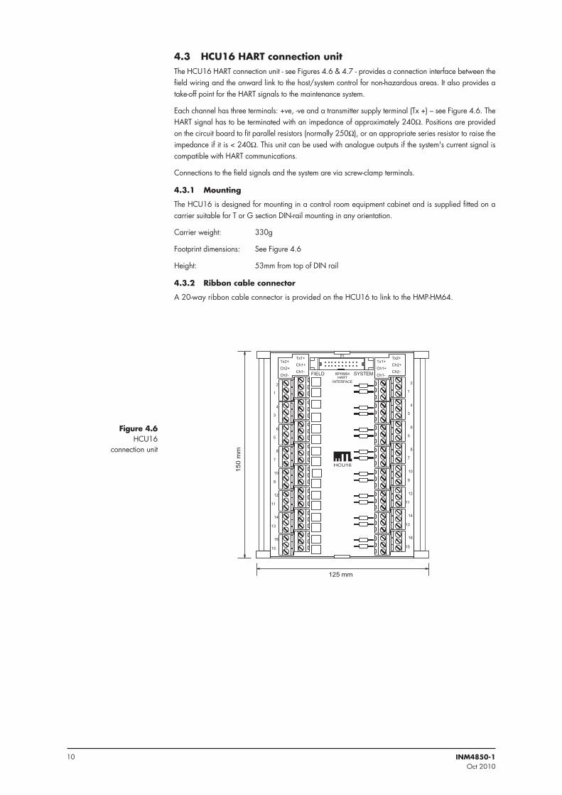
4 .3 HCU16 HART connection unitThe HCU16 HART connection unit - see Figures 4.6 & 4.7 - provides a connection interface between the field wiring and the onward link to the host/system control for non-hazardous areas. It also provides a take-off point for the HART signals to the maintenance system.
Each channel has three terminals: +ve, -ve and a transmitter supply terminal (Tx +) – see Figure 4.6. The HART signal has to be terminated with an impedance of approximately 240W. Positions are provided on the circuit board to fit parallel resistors (normally 250W), or an appropriate series resistor to raise the impedance if it is < 240W. This unit can be used with analogue outputs if the system's current signal is compatible with HART communications.
Connections to the field signals and the system are via screw-clamp terminals.
4 .3 .1 Mounting
The HCU16 is designed for mounting in a control room equipment cabinet and is supplied fitted on a carrier suitable for T or G section DIN-rail mounting in any orientation.
Carrier weight: 330g
Footprint dimensions: See Figure 4.6
Height: 53mm from top of DIN rail
4 .3 .2 Ribbon cable connector
A 20-way ribbon cable connector is provided on the HCU16 to link to the HMP-HM64.
������
�����
�
����������
����� ���
���
��
������
��
���
���
��
������
���
��
�����
��
��
��
�
�
�
�
�
��
��
��
��
�
�
�
�
��
��
��
�
�
�
�
�
��
��
��
��
�
�
�
�
������ ����
��
Figure 4 .6HCU16
connection unit

11INM4850-1Oct 2010
���������������
���������������
���������������
���������������
���������������
���������������
���������������
���������������
���������������
���������������
���������������
���������������
���������������
���������������
���������������
���������������
���������������
������������������
������������������
������������������
������������������
������������������
������������������
������������������
���������������
������������������
������������������
������������������
������������������
������������������
������������������
������������������
��������
���������
���������
�����������
���������������
���������������
���������������
���������������
����������
����������
�����������������
����������
����������
�����������������
��
���������������������
��
� ���������������������
������������ ���������������
������������
���������
Figure 4 .7HCU16
schematic diagram
12 INM4850-1Oct 2010
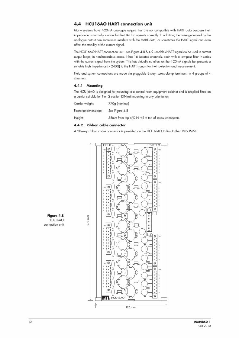
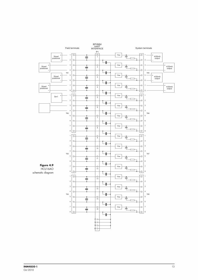
4 .4 HCU16AO HART connection unitMany systems have 4-20mA analogue outputs that are not compatible with HART data because their impedance is normally too low for the HART to operate correctly. In addition, the noise generated by the analogue output can sometimes interfere with the HART data, or sometimes the HART signal can even affect the stability of the current signal.
The HCU16AO HART connection unit - see Figure 4.8 & 4.9 - enables HART signals to be used in current output loops, in non-hazardous areas. It has 16 isolated channels, each with a low-pass filter in series with the current signal from the system. This has virtually no effect on the 4-20mA signals but presents a suitable high impedance (> 240W) to the HART signals for their detection and measurement.
Field and system connections are made via pluggable 8-way, screw-clamp terminals, in 4 groups of 4 channels.
4 .4 .1 Mounting
The HCU16AO is designed for mounting in a control room equipment cabinet and is supplied fitted on a carrier suitable for T or G section DIN-rail mounting in any orientation.
Carrier weight: 770g (nominal)
Footprint dimensions: See Figure 4.8
Height: 58mm from top of DIN rail to top of screw connectors
4 .4 .2 Ribbon cable connector
A 20-way ribbon cable connector is provided on the HCU16AO to link to the HMP-HM64.
��� ���
����� ������
�
�
�
�
�
�
�
�
���
�
�
�
�
�
�
�
�
�
�
�
�
�
�
�
�
���
�
�
�
�
�
�
�
�
�
�
�
�
�
�
�
�
�
�
�
�
�
�
�
�
���
���
�
�
�
�
�
�
�
�
���
�
�
�
�
�
�
�
�
���
����
������
�����
�Figure 4 .8HCU16AO
connection unit
13INM4850-1Oct 2010
��������������� ����������������
���
�
�
�
�
�
�
��
��
��
�
��
��
�
�
��
��
��
�
�
�
�
�
���
�
�
�
�
�
��
�
�
�
�
�
��
�
�
�
�
�
���
��
������������
�
�
������������
�
�
������������
�
�
������������
�
�
���������������
�
�
�
�
�
�
�
�
���������������
���������������
���������������
����
���������
�������
������
������
������
������
������
������
������
������
������
������
������
������
������
������
������
������
�
�
�
�
�
���
�
�
�
�
�
��
�
�
�
�
�
���
�
�
�
�
�
Figure 4 .9HCU16AO
schematic diagram
14 INM4850-1Oct 2010
4 .5 MTL customised backplanesMTL has a range of customised backplanes that accept MTL4500 Series isolators. These have been produced for various types of DCS and PLC equipment and have system connectors that suit the equipment type. Many are fitted with a DIN41651 20-way ribbon cable connector to enable the backplane to be connected to a HART maintenance system. Check with MTL for availability.
Other types of backplane are available that have provision for the inclusion of an MTL4850 module on the backplane itself. These are dealt with in the next section.
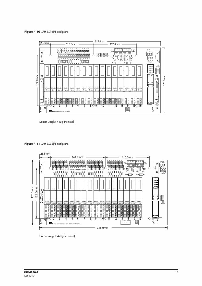
4 .6 CPH-SC16(R) and CPH-SC32(R) backplanesThe CPH-SC16, CPH-SC16R, CPH-SC32 and CPH-SC32R backplanes are designed for use with the MTL4500 series analogue input and output modules. Each backplane can accommodate 16 x MTL4500 modules as well as an MTL4850 HART multiplexer module.
4 .6 .1 CPH-SC16 and CPH-SC16R backplanes
Each of these backplanes will support 16 HART channels, but a second CPH-SC16 (or 16R) backplane can be connected to utilise the 32 channel capacity of the MTL4850. They are designed primarily for use with the MTL4541, or MTL4541A, analogue input modules and the MTL4546 analogue output modules.
The CPH-SC16R version has 250W resistors across each of the control system terminal to provide a 1–5V signal for the host. Only the MTL4541 and MTL4541A modules may be used with this version.
Connectors P1 and P2 at each end of the backplane are provided for linking a pair of CPH-SC16(or 16R) backplanes to utilise the full 32 channel capacity of the MTL4850. See Section 4.11 for additional details.
If a pair of backplanes is linked in this way, only one will have the MTL4850 fitted. The MTL4850 is fitted to the backplane that carries modules 1–16: the RS485 serial link should also be connected to this backplane.
4 .6 .2 CPH-SC32 and CPH-SC32R backplanes
Each of these backplanes will support 32 HART channels. They are designed primarily for use with the MTL4544, or MTL4544A analogue input modules and the MTL4549, or MTL4549C, analogue output modules.
The CPH-SC32R version has 250W resistors across each of the control system terminal to provide a 1–5V signal for the host. Only the MTL4544 modules may be used with this version.
4 .6 .3 RS485 communication connections
All of these backplanes have two RS485 ports fitted - see Figure 4.10 and 4.11 - to connect the backplane to the PC running the maintenance software and to onward link to other backplanes or similar HART interfaces. If a pair of backplanes is linked, the RS485 serial link should be connected only to the one carrying the MTL4850.
Full details of this communications link are provided in Sections 4.12.
4 .6 .4 DC power connections
The backplanes have dual redundant 24V dc supply feeds via independent 4-way, screw-clamp, terminal connectors. LED indicators are provided to indicate the presence of power to each of the redundant power inputs. Inline input diodes prevent interaction between the two power supplies and 0.5A fuses protect against over current.
Power requirements
Voltage: 20–35V dc
Current (with all channels at 20mA): 0.65A max. @ 24V dc - CPH-SC16(R)
1.2A max. @ 24V dc - CPH-SC32(R)
See Section 4.10.3 for connection details.
4 .6 .5 HART addressing
A 6-way DIP switch (SW1) is provided on the backplane to enable a unique HART address to be set for the MTL4850. The switch is binary coded and the relevant ‘bits’ should be switched to the ON position. See Section 5.3.2 for additional information.
15INM4850-1Oct 2010
����������� ������������� ������ �������
���
����������������
����
� � � � � � �
� � � � � � �
��� ���� ���� ��
� �� ������ ���� ��
�����������
���
����
��� ���
�
�
�
��
���
����
����
���
����
����
� �
����� �����
�
�������
��
�������
��
�������
��
�������
��
�������
��
�������
��
�������
��
�������
��
�������
��
�������
��
�������
��
�������
��
�������
��
�������
��
�������
��
�������
��
�������
��
�����
����
���
� � ������
������ � �
������
��������
����
����������������
�����������
����
��
�� � � � � � � �� ���� ���� �� ��
�� ��
��� ���
���
���
��� ������ ����� ���
���
���
������
� � �
�����
���
� � � � � ��
� � � � � � � � � ������ ������ �� �� ���� ����������
��� ����� ����
�� �����������������
�� �� �����
����������������
���� ����
� � �������
������� � �
�������
���
�������
���
�������
���
�������
���
�������
���
�������
���
�������
���
�������
���
�������
���
�������
���
�������
���
�������
���
�������
���
�������
���
�������
���
�������
���
��
��
��
����
���
����
����
���
����
����
�� ��
������ ������
�������
�������
����
����
�����
����
��
������
����
� �����
���� ����� ������������� � ���� �������
�����������
������
������
���
���
���
���
Figure 4 .10 CPH-SC16(R) backplane
Figure 4 .11 CPH-SC32(R) backplane
Carrier weight: 415g (nominal)
Carrier weight: 420g (nominal)
16 INM4850-1Oct 2010
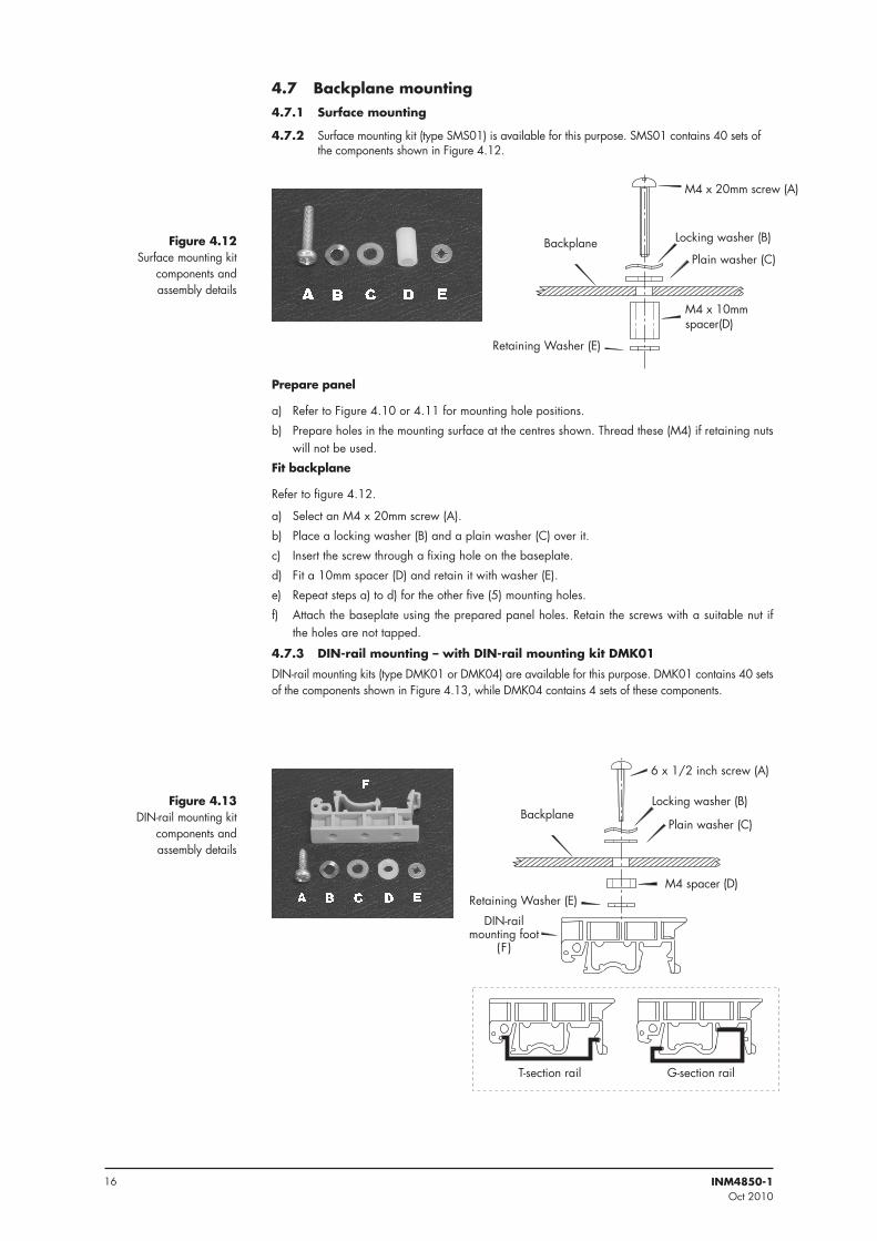
4 .7 Backplane mounting 4 .7 .1 Surface mounting
4 .7 .2 Surface mounting kit (type SMS01) is available for this purpose. SMS01 contains 40 sets of the components shown in Figure 4.12.
Prepare panel
a) Refer to Figure 4.10 or 4.11 for mounting hole positions.
b) Prepare holes in the mounting surface at the centres shown. Thread these (M4) if retaining nuts will not be used.
Fit backplane
Refer to figure 4.12.
a) Select an M4 x 20mm screw (A).
b) Place a locking washer (B) and a plain washer (C) over it.
c) Insert the screw through a fixing hole on the baseplate.
d) Fit a 10mm spacer (D) and retain it with washer (E).
e) Repeat steps a) to d) for the other five (5) mounting holes.
f) Attach the baseplate using the prepared panel holes. Retain the screws with a suitable nut if the holes are not tapped.
4 .7 .3 DIN-rail mounting – with DIN-rail mounting kit DMK01
DIN-rail mounting kits (type DMK01 or DMK04) are available for this purpose. DMK01 contains 40 sets of the components shown in Figure 4.13, while DMK04 contains 4 sets of these components.
������������������
� ��������������
�����������������
����� ���
��������������������
����������������
Figure 4 .12Surface mounting kit
components and assembly details
���������������������
��
������������ ������������
���������������
�������������� �������
����������������� ����������
����������������
Figure 4 .13DIN-rail mounting kit
components and assembly details
17INM4850-1Oct 2010
Fit backplane
Refer to figure 4.13.
a) Select a mounting screw (A).
b) Place a locking washer (B) and a plain washer (C) over it.
c) Insert the screw through a fixing hole on the baseplate.
d) Fit a spacer (D) and retain it with washer (E).
e) Repeat steps a) to e) for the other five (5) mounting holes.
f) Fit the mounting feet (F) onto the DIN-rail in roughly the correct positions.
g) Offer up the baseplate to the mounting feet on the DIN rail, locate the screws into the middle holes in the feet and secure each in turn. Return to tighten each screw before finishing.
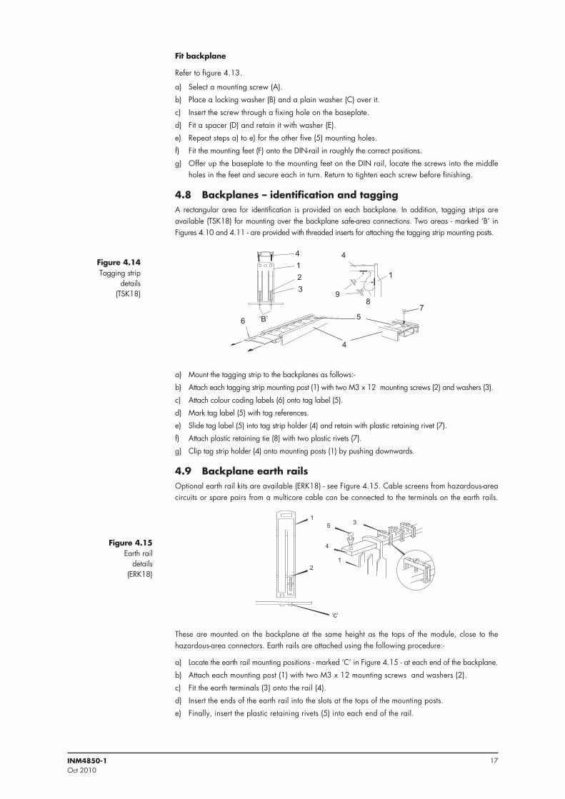
4 .8 Backplanes – identification and taggingA rectangular area for identification is provided on each backplane. In addition, tagging strips are available (TSK18) for mounting over the backplane safe-area connections. Two areas - marked ‘B’ in Figures 4.10 and 4.11 - are provided with threaded inserts for attaching the tagging strip mounting posts.
a) Mount the tagging strip to the backplanes as follows:-
b) Attach each tagging strip mounting post (1) with two M3 x 12 mounting screws (2) and washers (3).
c) Attach colour coding labels (6) onto tag label (5).
d) Mark tag label (5) with tag references.
e) Slide tag label (5) into tag strip holder (4) and retain with plastic retaining rivet (7).
f) Attach plastic retaining tie (8) with two plastic rivets (7).
g) Clip tag strip holder (4) onto mounting posts (1) by pushing downwards.
4 .9 Backplane earth railsOptional earth rail kits are available (ERK18) - see Figure 4.15. Cable screens from hazardous-area circuits or spare pairs from a multicore cable can be connected to the terminals on the earth rails.
These are mounted on the backplane at the same height as the tops of the module, close to the hazardous-area connectors. Earth rails are attached using the following procedure:-
a) Locate the earth rail mounting positions - marked ‘C’ in Figure 4.15 - at each end of the backplane.
b) Attach each mounting post (1) with two M3 x 12 mounting screws and washers (2).
c) Fit the earth terminals (3) onto the rail (4).
d) Insert the ends of the earth rail into the slots at the tops of the mounting posts.
e) Finally, insert the plastic retaining rivets (5) into each end of the rail.
�
�
�
�
�
�
�
��
����
�
�
���
�
�
�
���
Figure 4 .14Tagging strip
details (TSK18)
Figure 4 .15Earth rail
details (ERK18)
18 INM4850-1Oct 2010
4 .10 Backplanes – connections4 .10 .1 Hazardous area - field wiring connections
Personnel that carry out connection of wiring to or from hazardous areas must be correctly trained. Unless this work is done correctly, it can endanger the lives of site workers and seriously damage equipment.
Hazardous area wiring is terminated on the isolator modules using the blue terminals provided on them. For full information on the wiring of MTL4500 isolators consult MTL publication INM4500.
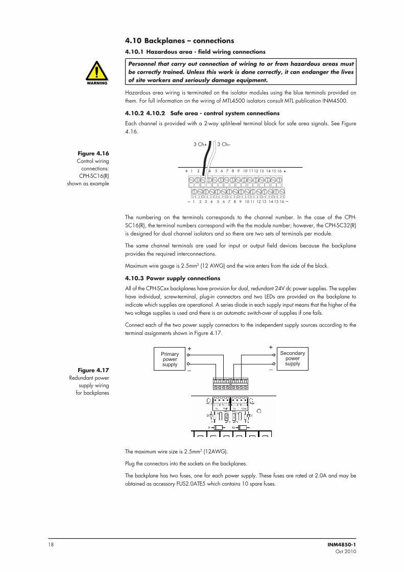
4 .10 .2 4 .10 .2 Safe area - control system connections
Each channel is provided with a 2-way split-level terminal block for safe area signals. See Figure 4.16.
���������������������������������������� ������������������
���������������������������������������� ������������������
�
�
�
�
����� �����
The numbering on the terminals corresponds to the channel number. In the case of the CPH-SC16(R), the terminal numbers correspond with the the module number; however, the CPH-SC32(R) is designed for dual channel isolators and so there are two sets of terminals per module.
The same channel terminals are used for input or output field devices because the backplane provides the required interconnections.
Maximum wire gauge is 2.5mm2 (12 AWG) and the wire enters from the side of the block.
4 .10 .3 Power supply connections
All of the CPH-SCxx backplanes have provision for dual, redundant 24V dc power supplies. The supplies have individual, screw-terminal, plug-in connectors and two LEDs are provided on the backplane to indicate which supplies are operational. A series diode in each supply input means that the higher of the two voltage supplies is used and there is an automatic switch-over of supplies if one fails.
Connect each of the two power supply connectors to the independent supply sources according to the terminal assignments shown in Figure 4.17.
��
�
������������������ �
��������������������
The maximum wire size is 2.5mm2 (12AWG).
Plug the connectors into the sockets on the backplanes.
The backplane has two fuses, one for each power supply. These fuses are rated at 2.0A and may be obtained as accessory FUS2.0ATE5 which contains 10 spare fuses.
Figure 4 .16Control wiring
connections: CPH-SC16(R)
shown as example
Figure 4 .17Redundant power
supply wiring for backplanes
19INM4850-1Oct 2010
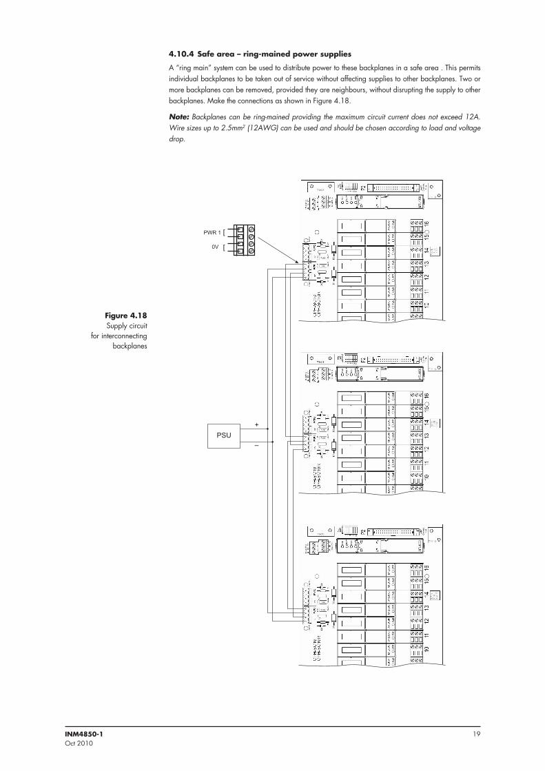
4 .10 .4 Safe area – ring-mained power supplies
A “ring main” system can be used to distribute power to these backplanes in a safe area . This permits individual backplanes to be taken out of service without affecting supplies to other backplanes. Two or more backplanes can be removed, provided they are neighbours, without disrupting the supply to other backplanes. Make the connections as shown in Figure 4.18.
Note: Backplanes can be ring-mained providing the maximum circuit current does not exceed 12A. Wire sizes up to 2.5mm2 (12AWG) can be used and should be chosen according to load and voltage drop.
����
�
�����
��
�
�
Figure 4 .18Supply circuit
for interconnecting backplanes
20 INM4850-1Oct 2010
4 .11 Cabling recommendations4 .11 .1 HART signals cable
HART signal cables are used to connect the CPH-SC backplane with a HART connection unit or an IS backplane. This connection is made with a 20-way ribbon cable.
Standard lengths of this 20-way cable are available from MTL using the part number HM64RIB20-x.x, where the x.x denotes lengths between 0.5 and 6.0 metres.
Connector type 20-way DIN 41651 bump polarised
Cable 0.05 inch pitch standard ribbon
Maximum length 15m / 50ft
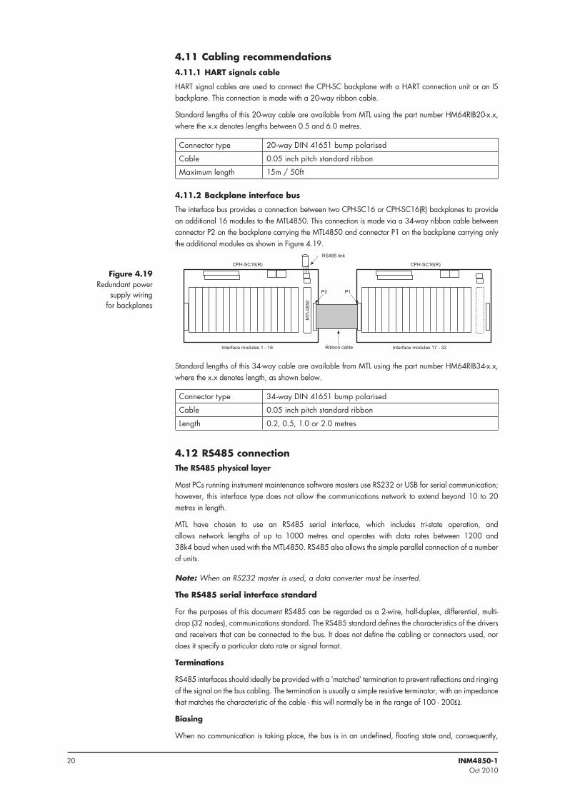
4 .11 .2 Backplane interface bus
The interface bus provides a connection between two CPH-SC16 or CPH-SC16(R) backplanes to provide an additional 16 modules to the MTL4850. This connection is made via a 34-way ribbon cable between connector P2 on the backplane carrying the MTL4850 and connector P1 on the backplane carrying only the additional modules as shown in Figure 4.19.
����
����
���
����������� �����������
������������������� ��������������������
����������
�� ����� �
Standard lengths of this 34-way cable are available from MTL using the part number HM64RIB34-x.x, where the x.x denotes length, as shown below.
Connector type 34-way DIN 41651 bump polarised
Cable 0.05 inch pitch standard ribbon
Length 0.2, 0.5, 1.0 or 2.0 metres
4 .12 RS485 connectionThe RS485 physical layer
Most PCs running instrument maintenance software masters use RS232 or USB for serial communication; however, this interface type does not allow the communications network to extend beyond 10 to 20 metres in length.
MTL have chosen to use an RS485 serial interface, which includes tri-state operation, and allows network lengths of up to 1000 metres and operates with data rates between 1200 and 38k4 baud when used with the MTL4850. RS485 also allows the simple parallel connection of a number of units.
Note: When an RS232 master is used, a data converter must be inserted.
The RS485 serial interface standard
For the purposes of this document RS485 can be regarded as a 2-wire, half-duplex, differential, multi-drop (32 nodes), communications standard. The RS485 standard defines the characteristics of the drivers and receivers that can be connected to the bus. It does not define the cabling or connectors used, nor does it specify a particular data rate or signal format.
Terminations
RS485 interfaces should ideally be provided with a ‘matched’ termination to prevent reflections and ringing of the signal on the bus cabling. The termination is usually a simple resistive terminator, with an impedance that matches the characteristic of the cable - this will normally be in the range of 100 - 200W.
Biasing
When no communication is taking place, the bus is in an undefined, floating state and, consequently,
Figure 4 .19Redundant power
supply wiring for backplanes
21INM4850-1Oct 2010
noise on the bus may be decoded as real characters. Well-written software should discard most of these characters, but the system may be further protected by biasing the bus to a known state and thereby preventing the reception of ‘false’ characters.
MTL4850 multiplexer modules from MTL have no built-in facility for terminating or biasing the network; as this is often provided by the RS232/RS485 converter.
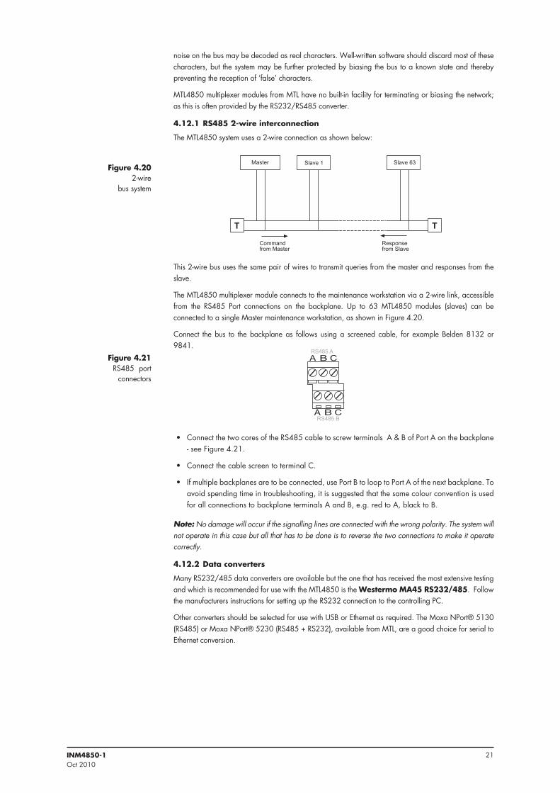
4 .12 .1 RS485 2-wire interconnection
The MTL4850 system uses a 2-wire connection as shown below:
������� ��������������
� �
������� ����������
�������� ���������
This 2-wire bus uses the same pair of wires to transmit queries from the master and responses from the slave.
The MTL4850 multiplexer module connects to the maintenance workstation via a 2-wire link, accessible from the RS485 Port connections on the backplane. Up to 63 MTL4850 modules (slaves) can be connected to a single Master maintenance workstation, as shown in Figure 4.20.
Connect the bus to the backplane as follows using a screened cable, for example Belden 8132 or 9841.
�������
�������
• Connect the two cores of the RS485 cable to screw terminals A & B of Port A on the backplane - see Figure 4.21.
• Connect the cable screen to terminal C.
• If multiple backplanes are to be connected, use Port B to loop to Port A of the next backplane. To avoid spending time in troubleshooting, it is suggested that the same colour convention is used for all connections to backplane terminals A and B, e.g. red to A, black to B.
Note: No damage will occur if the signalling lines are connected with the wrong polarity. The system will not operate in this case but all that has to be done is to reverse the two connections to make it operate correctly.
4 .12 .2 Data converters
Many RS232/485 data converters are available but the one that has received the most extensive testing and which is recommended for use with the MTL4850 is the Westermo MA45 RS232/485. Follow the manufacturers instructions for setting up the RS232 connection to the controlling PC.
Other converters should be selected for use with USB or Ethernet as required. The Moxa NPort® 5130 (RS485) or Moxa NPort® 5230 (RS485 + RS232), available from MTL, are a good choice for serial to Ethernet conversion.
Figure 4 .202-wire
bus system
Figure 4 .21RS485 port
connectors
22 INM4850-1Oct 2010
5 MODULES
5 .1 MTL4850 – installationPlace the MTL4850 over its marked connector in the position on the backplane, press it evenly and fully onto the backplane before tightening the two (captive) mounting screws. All safe-area circuit and power connections are made through this connector, so it must be seated properly on the backplane.
If the module does not operate correctly, the module mounting should be the first point to check.
5 .2 Isolator modules (if used)If the backplane accommodates isolators, refer to instruction manual INM4500 for information on wiring hazardous-area connectors for MTL4500 Series isolators.
Position each isolator module in its appropriate location on the backplane. Ensure that the module is not tilted, which could damage the connector pins, then press it carefully to the backplane. All safe-area circuit and power connections are made through this connector.
Personnel that carry out connection of wiring to or from hazardous areas must be correctly trained. Unless this work is done correctly, it can endanger the lives of site workers and seriously damage equipment.
Hazardous area wiring is terminated on the isolator modules using the blue terminals provided on them. For full information on the wiring of MTL4500 isolators consult MTL publication INM4500.
5 .3 MTL4850 module5 .3 .1 Setting and configuration
The speed for the RS485 interface is autodetected within the range 38400, 19200, 9600 or 1200 baud.
5 .3 .2 HART address
Up to 63 MTL4850 multiplexer modules can be connected to a single maintenance workstation. Each MTL4850 must have a unique address, which is set using the DIP switches located beside the module on the circuit board. The address switches are binary coded and the address is set by constructing the required number from the switch options provided, i.e. 1, 2, 4, 8, 16 and 32. For example, address number 29 would be set by putting switches 16, 8, 4 and 1 in the ON position (16 + 8 + 4 + 1 = 29).
Note, the HMP-HM64 can only be set to even numbers as the other module adopts the odd addresses. See Section 4.2.5.
5 .3 .3 Operation at power-up
The MTL4850 system is controlled by a host computer running instrument management software. Although the software is needed to operate the system, some checks can be made on the correct functioning of the hardware in isolation. These checks are made by observing the operation of the LEDs on top of the MTL4850.
5 .3 .3 .1 Correct operation
At power on, the power (PWR) LED should light and the multiplexer should start to build, or rebuild, an internal scan list of the HART loops connected to it. This will be indicated by a regular flashing sequence (equal on and off duration) of the Fault LED. At the end of this process the Fault LED should go OFF to indicate that it is now in its “running” state.
5 .3 .3 .2 Problems
If problems occurred during this power up sequence the Fault LED will either emit short and long flashes to indicate that it could not find any HART loops, or it will adopt a steady ON state to indicate that a fault was detected and the process of building the list was halted. The MTL4850 is delivered with the default of “scanning disabled”. In either case the instrument maintenance software can be used to change the MTL4850’s scanning mode.
5 .3 .3 .3 Scan list
Each loop connected to an MTL4850 is added to the scan list if a HART device is detected on power up or if the instrument maintenance software resets the MTL4850. Loops can be added individually or removed from the scan list using the “loop rebuild“ facility in the instrument maintenance software.
5 .3 .3 .4 Scanning enabled
The MTL4850 scans continuously round all loops on the scan list.
23INM4850-1Oct 2010
6 FAULT FINDING AND ROUTINE MAINTENANCE
6 .1 Maintenance precautions for MTL4500 modulesMost codes of practice permit live maintenance on intrinsically safe devices and systems, provided that precautions are taken to preserve the integrity of the device or system. During live maintenance of MTL4500 modules, the hazardous-area connectors that plug into the tops of the modules are likely to be removed, so the cables going into the hazardous-area connectors must be reasonably flexible in order to allow connectors to be inserted and removed easily from the module tops.
When a hazardous area connector is unplugged, care must be taken to ensure that it is not laid in a position where it could come into contact with the backplane or backplane components. The backplane is connected to safe-area circuits and is therefore not intrinsically safe. An unprotected connector could by-pass the essential segregation between the safe-area and hazardous-area circuits. This can be avoided by:
a) plugging the connector into an MTL4599 dummy isolator or other uninstalled MTL4500 module directly upon removal (but NOT into any other module mounted on the backplane).
b) providing some method of securing the connector temporarily so that it cannot touch the backplane or the safe-area circuits.
6 .2 Fault finding on custom backplanes When fault finding, carry out the following steps as far as is necessary:
1. Check the condition of the installation to make sure that no damage or deterioration has occurred.
2. Check that backplane power LEDs are ON. If not, check the power supply fuse(s) and, if necessary, change any of them.
3. Check that the (PWR) power LED on the MTL4850 module is ON. If not, and the circuit board power LED is ON, replace the module.
4. Exchange potentially faulty isolator modules as follows.
a) Unplug the hazardous-area connector(s).
b) Unclip and remove the module from the backplane.*
c) Plug-in and secure the replacement unit on the backplane.
d) Replace the hazardous-area connector(s).
5. If an MTL4850 is changed, the HMS software does not recognise a replacement device until either:
a) the node name (stored within the MTL4850) is made the same as that of the removed device, using the HMS software.
b) the network is rebuilt; when the software will adopt automatically the node name of the replacement device.
* Potentially faulty modules should be tested in workshop conditions. Consult the INM4500 installation manual for details of how to test a module.
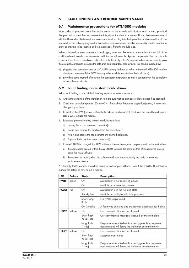
LED Colour State Description
PWR green Off Multiplexer is not receiving power
On Multiplexer is receiving power
FAULT red Off Multiplexer is in the running state
Steady flash Multiplexer build/rebuild is in progress
Short/long flash
No HART loops found
On (steady) A fault was detected and multiplexer operation has halted
HOST yellow Off No communication on the channel
Short flash(0.25 sec)
Correctly framed message received by the multiplexer
Long flash(1 sec)
Response transmitted—this is re-triggerable so repeated transmissions will leave the indicator permanently on
HART yellow Off No communication on the channel
Short flash(0.25 sec)
Message transmitted
Long flash(1 sec)
Response transmitted—this is re-triggerable so repeated transmissions will leave the indicator permanently on
24 INM4850-1Oct 2010
6 .3 Routine maintenanceIt is advisable to check the general condition of the installation occasionally to make sure that no damage or deterioration has occurred. The following should be checked at least once every two years (more frequently for particularly harsh environments):
1. Modules are of the types specified in the relevant documentation and are mounted in the correct positions on the associated backplanes.
2. Modules and hazardous area connectors are correctly and legibly tagged; that the connectors are plugged into the matching modules and that the tag details given comply with the relevant documentation.
3. Modules and hazardous area connectors are securely plugged into their matching sockets.
4. All connections to the backplane, and to the hazardous area connectors, are properly made.
5. Connecting cables to backplanes and to the hazardous area connectors are of the specified type and rating. They should be correctly routed and segregated and not frayed or otherwise damaged.
6. Cable screens are properly earthed.
Caution: It is strongly recommended that users only undertake the tests and routine maintenance described in sections 6.2 and 6.3. If an MTL4500 module is judged faulty, repairs or modifications MUST NOT be made as these may affect the intrinsic safety of the module. For repair or replacement, any faulty units or backplanes should be returned to MTL or the representative from which they were purchased.
7 SOFTWARE CONNECTIVITY
7 .1 Introduction
The MTL HART system provides access from a PC to the HART field devices for configuration, diagnostics and the monitoring of device performance. HART devices may be selected for regular status monitoring, and an alert issued if the status changes. An internal alarm log is also maintained which may be accessed through the Instrument Management Software (IMS) package - see Appendix B for further details.
In addition, MTL’s HART connection system supports dedicated software packages for valve positioners to optimise valve maintenance schedules.
7 .2 Communication modesMany of the IMS packages available are based upon the use of Device Driver (DD) files or upon FDT Technology as a frame for the various communication elements.
MTL provides the software driver files to support each of these approaches.
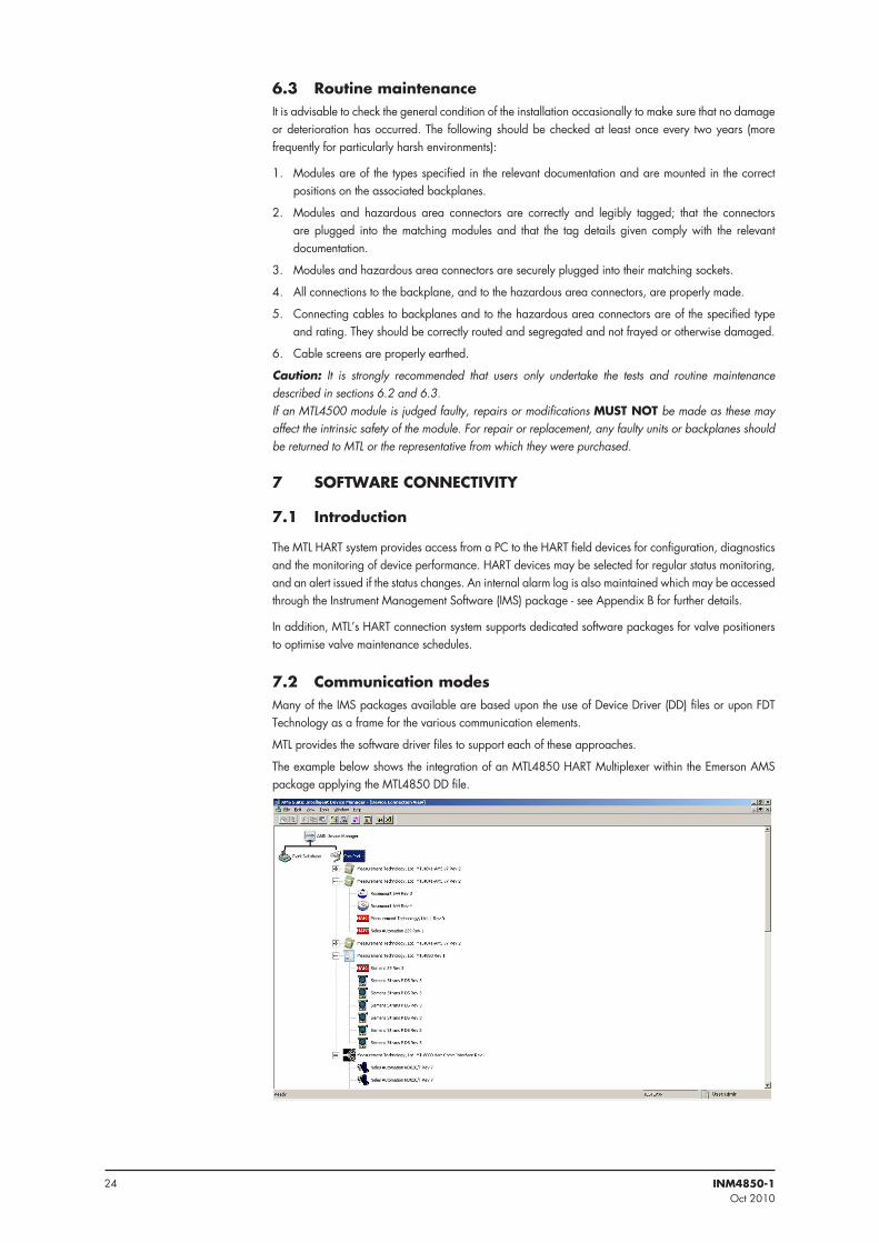
The example below shows the integration of an MTL4850 HART Multiplexer within the Emerson AMS package applying the MTL4850 DD file.
25INM4850-1Oct 2010
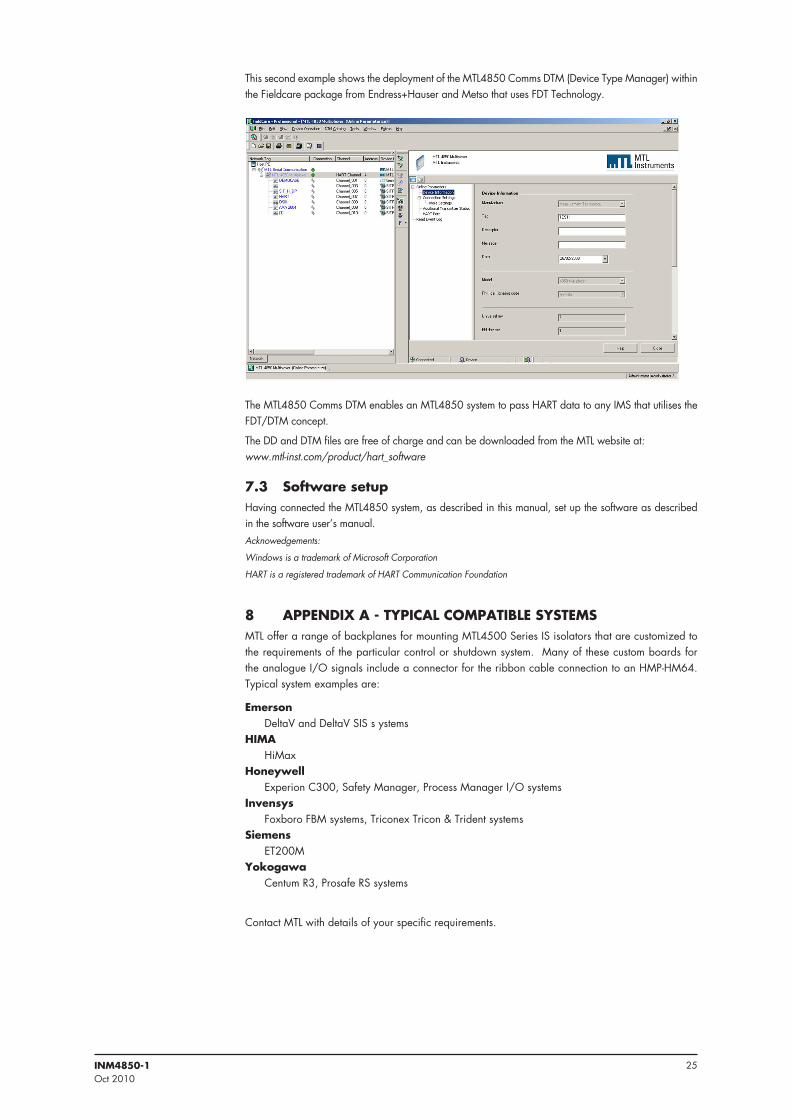
This second example shows the deployment of the MTL4850 Comms DTM (Device Type Manager) within the Fieldcare package from Endress+Hauser and Metso that uses FDT Technology.
The MTL4850 Comms DTM enables an MTL4850 system to pass HART data to any IMS that utilises the FDT/DTM concept.
The DD and DTM files are free of charge and can be downloaded from the MTL website at: www.mtl-inst.com/product/hart_software
7 .3 Software setupHaving connected the MTL4850 system, as described in this manual, set up the software as described in the software user’s manual.Acknowedgements:
Windows is a trademark of Microsoft Corporation
HART is a registered trademark of HART Communication Foundation
8 APPENDIX A - TYPICAL COMPATIBLE SYSTEMSMTL offer a range of backplanes for mounting MTL4500 Series IS isolators that are customized to the requirements of the particular control or shutdown system. Many of these custom boards for the analogue I/O signals include a connector for the ribbon cable connection to an HMP-HM64. Typical system examples are:
Emerson DeltaV and DeltaV SIS s ystemsHIMA HiMaxHoneywell Experion C300, Safety Manager, Process Manager I/O systemsInvensys Foxboro FBM systems, Triconex Tricon & Trident systemsSiemens ET200MYokogawa Centum R3, Prosafe RS systems
Contact MTL with details of your specific requirements.
26 INM4850-1Oct 2010
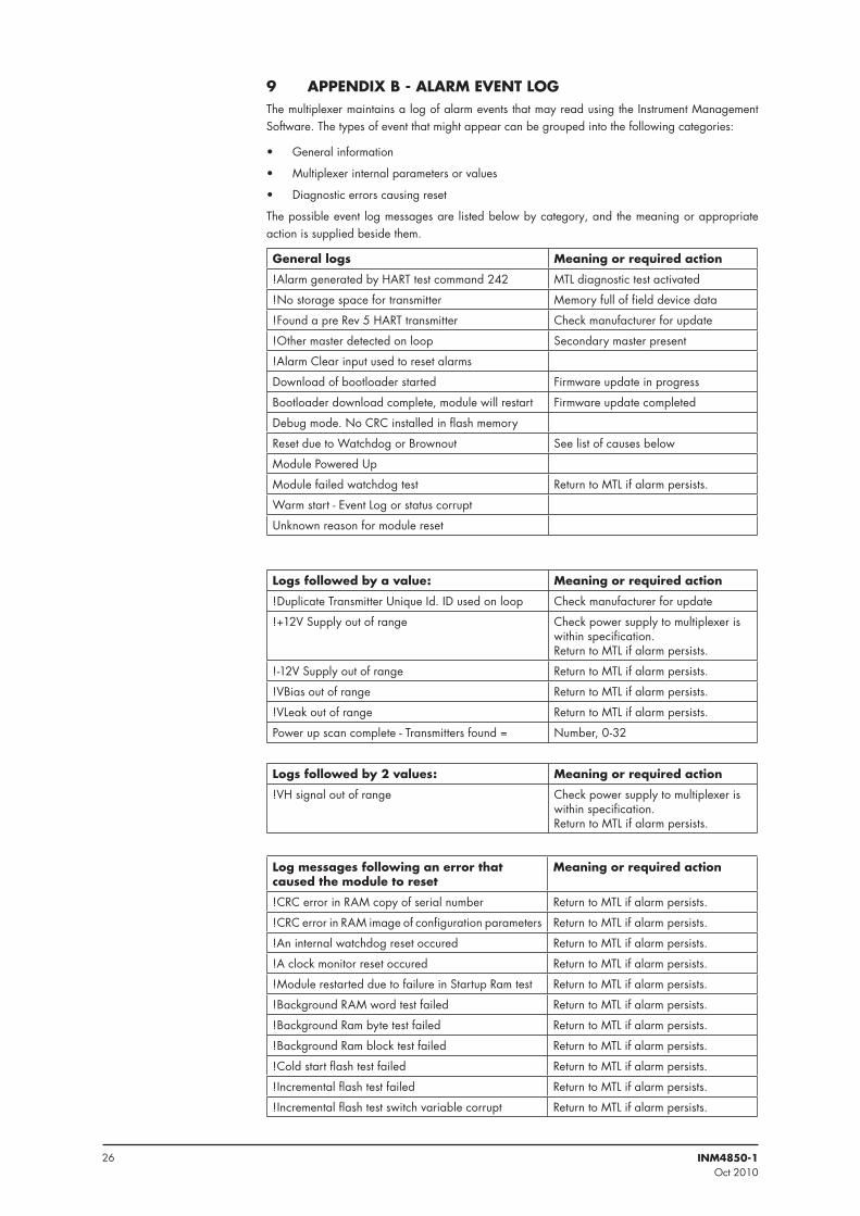
9 APPENDIX B - ALARM EVENT LOGThe multiplexer maintains a log of alarm events that may read using the Instrument Management Software. The types of event that might appear can be grouped into the following categories:
• General information
• Multiplexer internal parameters or values
• Diagnostic errors causing reset
The possible event log messages are listed below by category, and the meaning or appropriate action is supplied beside them.
General logs Meaning or required action
!Alarm generated by HART test command 242 MTL diagnostic test activated
!No storage space for transmitter Memory full of field device data
!Found a pre Rev 5 HART transmitter Check manufacturer for update
!Other master detected on loop Secondary master present
!Alarm Clear input used to reset alarms
Download of bootloader started Firmware update in progress
Bootloader download complete, module will restart Firmware update completed
Debug mode. No CRC installed in flash memory
Reset due to Watchdog or Brownout See list of causes below
Module Powered Up
Module failed watchdog test Return to MTL if alarm persists.
Warm start - Event Log or status corrupt
Unknown reason for module reset
Logs followed by a value: Meaning or required action
!Duplicate Transmitter Unique Id. ID used on loop Check manufacturer for update
!+12V Supply out of range Check power supply to multiplexer is within specification. Return to MTL if alarm persists.
!-12V Supply out of range Return to MTL if alarm persists.
!VBias out of range Return to MTL if alarm persists.
!VLeak out of range Return to MTL if alarm persists.
Power up scan complete - Transmitters found = Number, 0-32
Logs followed by 2 values: Meaning or required action
!VH signal out of range Check power supply to multiplexer is within specification. Return to MTL if alarm persists.
Log messages following an error that caused the module to reset
Meaning or required action
!CRC error in RAM copy of serial number Return to MTL if alarm persists.
!CRC error in RAM image of configuration parameters Return to MTL if alarm persists.
!An internal watchdog reset occured Return to MTL if alarm persists.
!A clock monitor reset occured Return to MTL if alarm persists.
!Module restarted due to failure in Startup Ram test Return to MTL if alarm persists.
!Background RAM word test failed Return to MTL if alarm persists.
!Background Ram byte test failed Return to MTL if alarm persists.
!Background Ram block test failed Return to MTL if alarm persists.
!Cold start flash test failed Return to MTL if alarm persists.
!Incremental flash test failed Return to MTL if alarm persists.
!Incremental flash test switch variable corrupt Return to MTL if alarm persists.
27INM4850-1Oct 2010
!Illegal instruction trap did not execute Return to MTL if alarm persists.
!Stack overflowed Return to MTL if alarm persists.
!Stack underflowed Return to MTL if alarm persists.
!Background diagnostics not running Return to MTL if alarm persists.
!RAM test not running Return to MTL if alarm persists.
!Bad call to diagnostic monitor Return to MTL if alarm persists.
!RAM test copy address corrupted Return to MTL if alarm persists.
!RAM corruption of TQ data in diag Return to MTL if alarm persists.
!Incremental CPU test failed Return to MTL if alarm persists.
Diagnostic session counter corrupted Return to MTL if alarm persists.
!EEPROM Group1 CRC error Return to MTL if alarm persists.
!EEPROM Group2 CRC error Return to MTL if alarm persists.
!RAM corruption in TQ data in EHS Return to MTL if alarm persists.
!An unused interrupt has occured Return to MTL if alarm persists.
!PLL out of lock Return to MTL if alarm persists.
!An illegal instruction has been encountered Return to MTL if alarm persists.
!Cold start CPU test failed Return to MTL if alarm persists.
!Bad call to program monitor Return to MTL if alarm persists.
!Stack pointer corrupted Return to MTL if alarm persists.
!Sequence error: Main initialisation Return to MTL if alarm persists.
!Sequence error: Main startup Return to MTL if alarm persists.
!Sequence error: First Field I/O Return to MTL if alarm persists.
!Sequence error: Timer Queue Return to MTL if alarm persists.
!Sequence error: Second Field I/O Return to MTL if alarm persists.
!Sequence error: Event handler Return to MTL if alarm persists.
!Sequence error: Diagnostic processing Return to MTL if alarm persists.
!Module state corrupted Return to MTL if alarm persists.
!RAM corruption of TQ data in main Return to MTL if alarm persists.
!The 1ms timer ISR executed late Return to MTL if alarm persists.
!The 1ms timer ISR executed early Return to MTL if alarm persists.
!Program monitor failed to report Return to MTL if alarm persists.
!Diagnostic monitor failed to report Return to MTL if alarm persists.
!Cancelled timer can’t be found Return to MTL if alarm persists.
!TQ Run out of sequence Return to MTL if alarm persists.
Single or occasional occurrence of these events may be due to noise or interruptions of the power supply, but multiple or frequent events might indicate problems with the installation, or with the module, in which case it should be returned to MTL for investigation.

Group Internet home page http://www.mtl-inst.com/
Members of The MTL Instruments Group
MTL Instruments Pty Limited9 /12 Billabong StreetStaffordQueensland 4053AustraliaTel: + 61 1300 308 374 Fax: + 61 1300 308 463E-mail: [email protected]
Cooper Electric (Shanghai) Co. Ltd.Room 2001, China Life Tower16 Chao Yang Men Wai StreetChao Yang District, BeijingChina 100020Tel: + 86 10 5980 0288 Fax: + 86 10 8562 5725E-mail: [email protected]
MTL Instruments sarlLes Carrés du Parc10 rue des Rosiéristes69410 Champagne au Mont d’OrFranceTel: +33 (0)4 78 64 98 32 Fax: +33 (0)4 78 35 79 41E-mail: [email protected]
MTL Instruments GmbHAn der Gümpgesbrücke 17D-41564 KaarstGermanyTel: +49 (0)2131 718930 Fax: +49 (0)2131 7189333E-mail: [email protected]
MTL IndiaNo. 36, Nehru StreetOff Old Mahabalipuram RoadSholinganallurChennai - 600 119IndiaTel: + 91 (0)44 24501660/24501857 Fax: + 91 (0)44 24501463E-mail: [email protected]
MTL Italia srlVia Cantù 11I - 20092 Cinisello Balsamo MIItalyTel: +39 (0)2 61802011 Fax: +39 (0)2 61294560E-mail: [email protected]
Cooper Crouse-Hinds Japan KKMT Building 3F2-7-5 Shiba DaimonMinato-ku TokyoJapan 105-0012Tel: +81 (0)3 6430 3128 Fax: +81 (0)3 6430 3129E-mail: [email protected]
Cooper Crouse-Hinds Korea12F, Vision Tower707-2 Yeoksam-dong, Gangnam-guSeoul 135-080South KoreaTel: +82 2 3484 6795 Fax: +82 2 3484 6778
MTL Instruments BVMTL Instruments BVTerheijdenseweg 4654825BK BredaThe NetherlandsTel: +31(0)76 7505360 Fax: +31(0)76 7505370 E-mail: [email protected]
Cooper Crouse-Hinds Pte Ltd.No.2 Serangoon North Avenue 5#06-01 Fu Yu BuildingSingapore 554911Tel: +65 6 487 7887 Fax: +65 6 487 7997E-mail: [email protected]
MTL InstrumentsVilla No. 4, Sector 2-17, Street 6PO Box 53234,Abu Dhabi, UAETel: +971 2 446 6840 Fax: +971 2 446 6841E-mail: [email protected]
Measurement Technology LimitedGreat Marlings, Butterfield, Luton, BedsEngland LU2 8DLTel: +44 (0)1582 723633 Fax: +44 (0)1582 422283E-mail: [email protected]
Cooper Crouse-Hinds MTL Inc3413 N. Sam Houston Parkway W.Suite 210Houston TX 77086USATel: +1 281 571 8065 Fax: +1 281 571 8069E-mail: [email protected]