Embed Size (px)
Citation preview
© 2010 Microchip Technology Inc. DS41385C
mTouch™ Advanced CapacitiveEvaluation Kits
User’s Guide
Note the following details of the code protection feature on Microchip devices:• Microchip products meet the specification contained in their particular Microchip Data Sheet.
• Microchip believes that its family of products is one of the most secure families of its kind on the market today, when used in the intended manner and under normal conditions.
• There are dishonest and possibly illegal methods used to breach the code protection feature. All of these methods, to our knowledge, require using the Microchip products in a manner outside the operating specifications contained in Microchip’s Data Sheets. Most likely, the person doing so is engaged in theft of intellectual property.
• Microchip is willing to work with the customer who is concerned about the integrity of their code.
• Neither Microchip nor any other semiconductor manufacturer can guarantee the security of their code. Code protection does not mean that we are guaranteeing the product as “unbreakable.”
Code protection is constantly evolving. We at Microchip are committed to continuously improving the code protection features of ourproducts. Attempts to break Microchip’s code protection feature may be a violation of the Digital Millennium Copyright Act. If such actsallow unauthorized access to your software or other copyrighted work, you may have a right to sue for relief under that Act.
Information contained in this publication regarding deviceapplications and the like is provided only for your convenienceand may be superseded by updates. It is your responsibility toensure that your application meets with your specifications.MICROCHIP MAKES NO REPRESENTATIONS ORWARRANTIES OF ANY KIND WHETHER EXPRESS ORIMPLIED, WRITTEN OR ORAL, STATUTORY OROTHERWISE, RELATED TO THE INFORMATION,INCLUDING BUT NOT LIMITED TO ITS CONDITION,QUALITY, PERFORMANCE, MERCHANTABILITY ORFITNESS FOR PURPOSE. Microchip disclaims all liabilityarising from this information and its use. Use of Microchipdevices in life support and/or safety applications is entirely atthe buyer’s risk, and the buyer agrees to defend, indemnify andhold harmless Microchip from any and all damages, claims,suits, or expenses resulting from such use. No licenses areconveyed, implicitly or otherwise, under any Microchipintellectual property rights.
DS41385C-page 2
Trademarks
The Microchip name and logo, the Microchip logo, dsPIC, KEELOQ, KEELOQ logo, MPLAB, PIC, PICmicro, PICSTART, PIC32 logo, rfPIC and UNI/O are registered trademarks of Microchip Technology Incorporated in the U.S.A. and other countries.
FilterLab, Hampshire, HI-TECH C, Linear Active Thermistor, MXDEV, MXLAB, SEEVAL and The Embedded Control Solutions Company are registered trademarks of Microchip Technology Incorporated in the U.S.A.
Analog-for-the-Digital Age, Application Maestro, CodeGuard, dsPICDEM, dsPICDEM.net, dsPICworks, dsSPEAK, ECAN, ECONOMONITOR, FanSense, HI-TIDE, In-Circuit Serial Programming, ICSP, Mindi, MiWi, MPASM, MPLAB Certified logo, MPLIB, MPLINK, mTouch, Octopus, Omniscient Code Generation, PICC, PICC-18, PICDEM, PICDEM.net, PICkit, PICtail, REAL ICE, rfLAB, Select Mode, Total Endurance, TSHARC, UniWinDriver, WiperLock and ZENA are trademarks of Microchip Technology Incorporated in the U.S.A. and other countries.
SQTP is a service mark of Microchip Technology Incorporated in the U.S.A.
All other trademarks mentioned herein are property of their respective companies.
© 2010, Microchip Technology Incorporated, Printed in the U.S.A., All Rights Reserved.
Printed on recycled paper.
ISBN: 978-1-60932-298-4Microchip received ISO/TS-16949:2002 certification for its worldwide
© 2010 Microchip Technology Inc.
headquarters, design and wafer fabrication facilities in Chandler and Tempe, Arizona; Gresham, Oregon and design centers in California and India. The Company’s quality system processes and procedures are for its PIC® MCUs and dsPIC® DSCs, KEELOQ® code hopping devices, Serial EEPROMs, microperipherals, nonvolatile memory and analog products. In addition, Microchip’s quality system for the design and manufacture of development systems is ISO 9001:2000 certified.
mTouch™ ADVANCED CAPACITIVE EVAL-
UATION KITS USER’S GUIDETable of Contents
Preface ........................................................................................................................... 5Introduction............................................................................................................ 5Document Layout .................................................................................................. 5Conventions Used in this Guide ............................................................................ 6Warranty Registration............................................................................................ 7Recommended Reading........................................................................................ 7The Microchip Web Site ...................................................................................... 10Development Systems Customer Change Notification Service .......................... 10Customer Support ............................................................................................... 11Document Revision History ................................................................................. 11
Chapter 1. Introduction to the Evaluation Boards1.1 Overview ...................................................................................................... 131.2 Operational Requirements ........................................................................... 151.3 Initial Board Setup ........................................................................................ 16
Chapter 2. Demonstration Application2.1 Introduction to the Touch Interface ............................................................... 172.2 Individual Touch Sense Demonstrations ...................................................... 18
Chapter 3. Using the mTouch™ Sensing Solution3.1 About the mTouch Sensing Solution Diagnostic Tool .................................. 213.2 MPLAB IDE integrated mTouch Diagnostic Tool GUI .................................. 21
Chapter 4. Evaluation Board Hardware4.1 Application Functional Overview .................................................................. 274.2 Board Components ...................................................................................... 324.3 Interfacing to the Evaluation Boards ............................................................ 38
Chapter 5. Troubleshooting5.1 Common Issues ........................................................................................... 41
Appendix A. Evaluation Board SchematicsAppendix B. mTouch™ PIC16F CSM State DiagramsIndex ............................................................................................................................. 53Worldwide Sales and Service .................................................................................... 54
© 2009 Microchip Technology Inc. DS41385C-page 3
mTouch™ Advanced Capacitive Evaluation Kits User’s
GuideDS41385C-page 4 © 2009 Microchip Technology Inc.
mTouch™ ADVANCED CAPACITIVEEVALUATION KITS USER’S GUIDE
Preface
INTRODUCTIONThis chapter contains general information that will be useful to know before you use an mTouch™ Advanced Capacitive Evaluation Kit. Items discussed in this chapter include:• Document Layout• Conventions Used in this Guide• Warranty Registration• Recommended Reading• The Microchip Web Site• Development Systems Customer Change Notification Service• Customer Support• Document Revision History
DOCUMENT LAYOUTThis document describes how to use an mTouch Advanced Capacitive Evaluation Kit as a development and demonstrative tool for PIC16F, PIC18F, PIC24F, PIC24H and PIC32MX MCU device capabilities and features. The document layout is as follows:• Chapter 1. Introduction to the Evaluation Boards – This chapter introduces the
mTouch Advanced Capacitive Evaluation Kits and provides an overview of their features.
• Chapter 2. Demonstration Application – This chapter describes the preprogrammed capacitive touch sense demonstration application.
• Chapter 3. Using the mTouch™ Sensing Solution – This chapter describes the diagnostic software and how to use it with an mTouch Advanced Capacitive Evaluation Kit.
• Chapter 4. Evaluation Board Hardware – This chapter provides a functional overview of the mTouch Advanced Capacitive Evaluation Kits and identifies the major hardware components.
• Chapter 5. Troubleshooting – This chapter provides troubleshooting tips for commonly encountered issues.
• Appendix A. “Evaluation Board Schematics” – This appendix provides
NOTICE TO CUSTOMERS
All documentation becomes dated, and this manual is no exception. Microchip tools and documentation are constantly evolving to meet customer needs, so some actual dialogs and/or tool descriptions may differ from those in this document. Please refer to our web site (www.microchip.com) to obtain the latest documentation available.Documents are identified with a “DS” number. This number is located on the bottom of each page, in front of the page number. The numbering convention for the DS number is “DSXXXXXA”, where “XXXXX” is the document number and “A” is the revision level of the document.For the most up-to-date information on development tools, see the MPLAB® IDE online help. Select the Help menu, and then Topics to open a list of available online help files.
© 2010 Microchip Technology Inc. DS41385C-page 5
mTouch™ Advanced Capacitive Evaluation Kits User’s Guide
detailed schematic diagrams of the evaluation boards.• Appendix B. “mTouch™ PIC16F CSM State Diagrams” – This appendix
provides PIC16F CSM state diagrams.
CONVENTIONS USED IN THIS GUIDEThis manual uses the following documentation conventions:
DOCUMENTATION CONVENTIONSDescription Represents Examples
Arial font:Italic characters Referenced books MPLAB® IDE User’s Guide
Emphasized text ...is the only compiler...Initial caps A window the Output window
A dialog the Settings dialogA menu selection select Enable Programmer
Quotes A field name in a window or dialog
“Save project before build”
Underlined, italic text with right angle bracket
A menu path File>Save
Bold characters A dialog button Click OKA tab Click the Power tab
Text in angle brackets < > A key on the keyboard Press <Enter>, <F1>Courier New font:Plain Courier New Sample source code #define START
Filenames autoexec.batFile paths c:\mcc18\h
Keywords _asm, _endasm, static
Command-line options -Opa+, -Opa-Bit values 0, 1
Constants 0xFF, ‘A’
Italic Courier New A variable argument file.o, where file can be any valid filename
Square brackets [ ] Optional arguments mcc18 [options] file [options]
Curly brackets and pipe character: { | }
Choice of mutually exclusive arguments; an OR selection
errorlevel {0|1}
Ellipses... Replaces repeated text var_name [, var_name...]
Represents code supplied by user
void main (void){ ...}
DS41385C-page 6 © 2010 Microchip Technology Inc.

Preface
WARRANTY REGISTRATIONPlease complete the enclosed Warranty Registration Card and mail it promptly. Sending in the Warranty Registration Card entitles you to receive new product updates. Interim software releases are available at the Microchip web site.
RECOMMENDED READINGThis user’s guide describes how to use an mTouch Advanced Capacitive Evaluation Kit. Other useful documents are listed below. The following Microchip documents are available and recommended as supplemental reference resources. The latest docu-mentation is available from the mTouch web page (www.microchip.com/mtouch).
Readme FilesFor the latest information on using other tools, read the tool-specific Readme files in the Readme subdirectory of the MPLAB® IDE installation directory. The Readme files contain update information and known issues that may not be included in this user’s guide.
Family Reference Manual SectionsFamily Reference Manual sections are available, which explain the operation of the PIC microcontroller family architecture and peripheral modules. The specifics of each device family are discussed in the individual family’s device data sheet.Users are specifically directed to the “Charge Time Measurement Unit (CTMU)” Family Reference Manual sections for a detailed discussion of this module, which is at the heart of the capacitive touch sense demonstration. Please refer to the Microchip web site for the latest version of these documents.
Device Data Sheets and Flash Programming SpecificationsRefer to the appropriate device data sheet for device-specific information and specifications. Also, refer to the appropriate device Flash Programming Specification for information on instruction sets and firmware development. These documents may be obtained from the Microchip web site or your local sales office.
16-bit MCU and DSC Programmer’s Reference Manual (DS70157)This manual is a software developer’s reference for the 16-bit PIC24F and PIC24H MCU, and 16-bit dsPIC30F and dsPIC33F DSC families of devices. It describes the instruction set in detail and also provides general information to assist in developing software for these device families.
MPLAB® Assembler Linker and Utilities for PIC24 MCUs and dsPIC® DSCs User’s Guide (DS51317)This document details Microchip Technology’s language tools for dsPIC® DSC devices based on GNU technology. The language tools discussed are:• MPLAB Assembler PIC24 MCUs and dsPIC® DSCs• MPLAB Linker PIC24 MCUs and dsPIC® DSCs• MPLAB Archiver/Librarian PIC24 MCUs and dsPIC® DSCs• Other Utilities
Note: Refer to “MIPS32® Architecture for Programmers Volume II: The MIPS32® Instruction Set” at www.mips.com for related information on PIC32 MCUs.
© 2010 Microchip Technology Inc. DS41385C-page 7
mTouch™ Advanced Capacitive Evaluation Kits User’s Guide
MPLAB® Assembler Linker and Utilities for PIC32 MCUs User’s Guide (DS51833)This document details Microchip Technology’s language tools for PIC32 MCU devices based on GNU technology. The language tools discussed are:• MPLAB Assembler PIC32 MCUs• MPLAB Linker PIC32 MCUs• MPLAB Archiver/Librarian PIC32 MCUs• Other Utilities
HI-TECH C® for PIC10/12/16 User’s Guide (DS51865)This document details the use of Microchip’s HI-TECH C Compiler for PIC10/12/16 MCUs, which is a free-standing, optimizing ANSI C compiler. It supports all PIC10, PIC12 and PIC16 series devices, as well as the PIC14000 device and the enhanced Mid-Range PIC® MCU architecture.
MPLAB® C Compiler for PIC18 MCUs User’s Guide (DS51288)
This document details the use of Microchip’s MPLAB C Compiler for PIC18 MCU devices to develop an application. The MPLAB C Compiler is a GNU-based language tool, based on source code from the Free Software Foundation (FSF). For more information about the FSF, see www.fsf.org.
MPLAB® C Compiler for PIC24 MCUs and dsPIC® DSCs User’s Guide (DS51284)This document details the use of Microchip’s MPLAB C Compiler for PIC24 MCUs and dsPIC DSC devices to develop an application. The MPLAB C Compiler is a GNU-based language tool, based on source code from the Free Software Foundation (FSF). For more information about the FSF, see www.fsf.org.
MPLAB® C Compiler for PIC32 MCUs User’s Guide (DS51686)This document details the use of Microchip’s MPLAB C Compiler for PIC32 MCU devices to develop an application. The MPLAB C Compiler is a GNU-based language tool, based on source code from the Free Software Foundation (FSF). For more information about the FSF, see www.fsf.org.
MPLAB® REAL ICE™ In-Circuit Emulator User’s Guide (DS51616)This document describes how to use the MPLAB REAL ICE in-circuit emulator as a development tool to emulate and debug firmware on a target board, as well as how to program devices.
MPLAB® IDE User’s Guide (DS51519)This document describes how to use the MPLAB IDE Integrated Development Environ-ment, as well as the MPLAB project manager, MPLAB editor and MPLAB SIM simulator. Use these development tools to help you develop and debug application code.
DS41385C-page 8 © 2010 Microchip Technology Inc.
Preface
Application NotesThere are several Application Notes available from Microchip that help in understanding capacitive touch applications. These include:• AN1101 “Introduction to Capacitive Sensing”• AN1102 “Layout and Physical Design Guidelines for Capacitive Sensing”• AN1103 “Software Handling for Capacitive Sensing”• AN1104 “Capacitive Multibutton Configurations”• AN1171 “Using the Capacitive Sensing Module on the PIC16F72X”• AN1202 “Capacitive Sensing with PIC10F”• AN1250 “Microchip CTMU for Capacitive Touch Applications”• AN1298 “Capacitive Touch Using Only an ADC (“CVD”)”
Microchip mTouch™ Sensing Solutions WebinarsCurrently, there are three online Webinars available for mTouch Sensing Solutions:• Introduction to mTouch™ Capacitive Touch Sensing• Capacitive mTouch™ Sensing Solutions: Design Guidelines• Overview of Charge Time Measurement Unit (CTMU)
© 2010 Microchip Technology Inc. DS41385C-page 9
mTouch™ Advanced Capacitive Evaluation Kits User’s Guide
THE MICROCHIP WEB SITEMicrochip provides online support through our web site at www.microchip.com. This web site is used as a means to make files and information easily available to customers. Accessible by using your favorite Internet browser, the web site contains the following information:• Product Support – Data sheets and errata, application notes and sample
programs, design resources, user’s guides and hardware support documents, latest software releases and archived software
• General Technical Support – Frequently Asked Questions (FAQs), technical support requests, online discussion groups, Microchip consultant program member listing
• Business of Microchip – Product selector and ordering guides, latest Microchip press releases, listing of seminars and events, listings of Microchip sales offices, distributors and factory representatives
DEVELOPMENT SYSTEMS CUSTOMER CHANGE NOTIFICATION SERVICEMicrochip’s customer notification service helps keep customers current on Microchip products. Subscribers will receive e-mail notification whenever there are changes, updates, revisions or errata related to a specified product family or development tool of interest.To register, access the Microchip web site at www.microchip.com, click on Customer Change Notification and follow the registration instructions.The Development Systems product group categories are:• Compilers – The latest information on Microchip C compilers and other language
tools. These include the MPLAB C compiler; MPASM™ and MPLAB 16-bit assemblers; MPLINK™ and MPLAB 16-bit object linkers; and MPLIB™ and MPLAB 16-bit object librarians.
• Emulators – The latest information on Microchip in-circuit emulators.This includes the MPLAB ICE 2000, MPLAB ICE 4000, MPLAB REAL ICE.
• In-Circuit Debuggers – The latest information on the Microchip in-circuit debugger, MPLAB ICD 2, and MPLAB ICD 3.
• MPLAB® IDE – The latest information on Microchip MPLAB IDE, the Windows® Integrated Development Environment for development systems tools. This list is focused on the MPLAB IDE, MPLAB SIM simulator, MPLAB IDE Project Manager and general editing and debugging features.
• Programmers – The latest information on Microchip programmers. These include the MPLAB PM3 and PRO MATE® II device programmers and the PICSTART® Plus and PICkit™ 1, 2 and 3 development programmers.
DS41385C-page 10 © 2010 Microchip Technology Inc.
Preface
CUSTOMER SUPPORTUsers of Microchip products can receive assistance through several channels:• Distributor or Representative• Local Sales Office• Field Application Engineer (FAE)• Technical SupportCustomers should contact their distributor, representative or FAE for support. Local sales offices are also available to help customers. A listing of sales offices and locations is included in the back of this document.Technical support is available through our web site at: http://support.microchip.com
DOCUMENT REVISION HISTORY
Revision A (April 2009)• Initial Release of this Document
Revision B (September 2009)• Added reference to PIC18F MCU• Added PIC18F CTMU Evaluation Board Schematic• Added PIC18F Block Diagram for the CTMU Board• Modified the Kit Contents list
Revision C (June 2010)This version of the document includes the following updates:• Added references to PIC24H and PIC32MX MCUs throughout the document• Modified the Kit Contents list• Added the PIC32 CVD Touch Evaluation Board• Added block diagrams for the PIC24H CVD and PIC32 CVD Evaluation Boards• Updated PIC16F CSM/CVD Evaluation Board schematic and layout
© 2010 Microchip Technology Inc. DS41385C-page 11

mTouch™ Advanced Capacitive Evaluation Kits User’s Guide
NOTES:
DS41385C-page 12 © 2010 Microchip Technology Inc.
mTouch™ ADVANCED CAPACITIVEEVALUATION KITS USER’S GUIDE
Chapter 1. Introduction to the Evaluation Boards
Thank you for purchasing a Microchip Technology mTouch Advanced Capacitive Evaluation Kit. Depending on the kit purchased, up to four individual evaluation boards are provided. These evaluation boards are intended to introduce and demonstrate the possibilities for capacitive touch sense applications on the PIC16F, PIC18F, PIC24F, (DM183026-2 kit), PIC24H (AC243026 kit) and PIC32MX microcontroller platforms.
This chapter introduces the evaluation kits and provides an overview of their features. Topics covered include:• Overview• Operational Requirements• Initial Board Setup
1.1 OVERVIEWThe mTouch Advanced Capacitive Evaluation Kits provide a simple platform for developing a variety of capacitive touch sense applications. Depending on the kit purchased, up to four evaluation boards are included with PIC16F, PIC18F, PIC24F, PIC24H and PIC32MX microcontrollers, with four sensor daughter boards, as shown in Figure 1-1 and Figure 1-2. These evaluation kits are intended to be used to develop a capacitive touch sense application using Microchip’s mTouch technologies. A kit is used by first connecting a sensor board, and then supplying power to the board via USB, PICkit™ 3 or the PICkit Serial Analyzer. The connector, J3/J4, with numbers from 0 to 15, is the connector for sensing channels. The numbers, from 0 to 15 for PIC16F, PIC24F, PIC24H and PIC32MX, and from 0 to 12 for PIC18F, represents the microcontroller’s sensing channel. The vertical 2-row header is for debugging, to give easy access to some of the microcontroller pins. Debugging may also be done by Microchip programmers and the I2C™ or USB is used to communicate with the mTouch diagnostic tool.When using an evaluation kit out of the box, the default function of the LEDs is to illuminate on a key press. All functionalities may be reprogrammed by using a Microchip programmer and reprogramming the firmware in the device. The firmware supplied with the evaluation kit is optimized to use with the four sensor boards supplied.The USB connection supplies power to the board; no additional external power supply is needed. For independent operation, the evaluation board may be disconnected from the PC and powered at test points. For the PIC18F, PIC24F and PIC32MX evaluation boards, the USB also provides communications with the MPLAB mTouch Diagnostic Tool. The PIC16F and PIC24H evaluation boards use the PICkit Serial Analyzer to communicate via I2C to the PC. The MPLAB mTouch application allows users to monitor the performance of the touch sensors and to optimize the sensor response. A separate, 6-wire programming interface allows users to replace the preprogrammed
Note: This Evaluation Kit is intended as a functional evaluation of Microchip’s mTouch Capacitive Sensing Solutions. It has not been designed for use in noisy or production - level testing environment. Please refer Microchip Application Notes for guidelines when attempting to design a product to be used or deployed in such environments.
© 2010 Microchip Technology Inc. DS41385C-page 13
mTouch™ Advanced Capacitive Evaluation Kits User’s Guide
demonstration firmware with their own applications using Microchip’s MPLAB®
Integrated Development Environment (IDE) and In-Circuit Serial Programming™ (ICSP™). This allows the board to also be used as a test platform for capacitive touch sense applications.
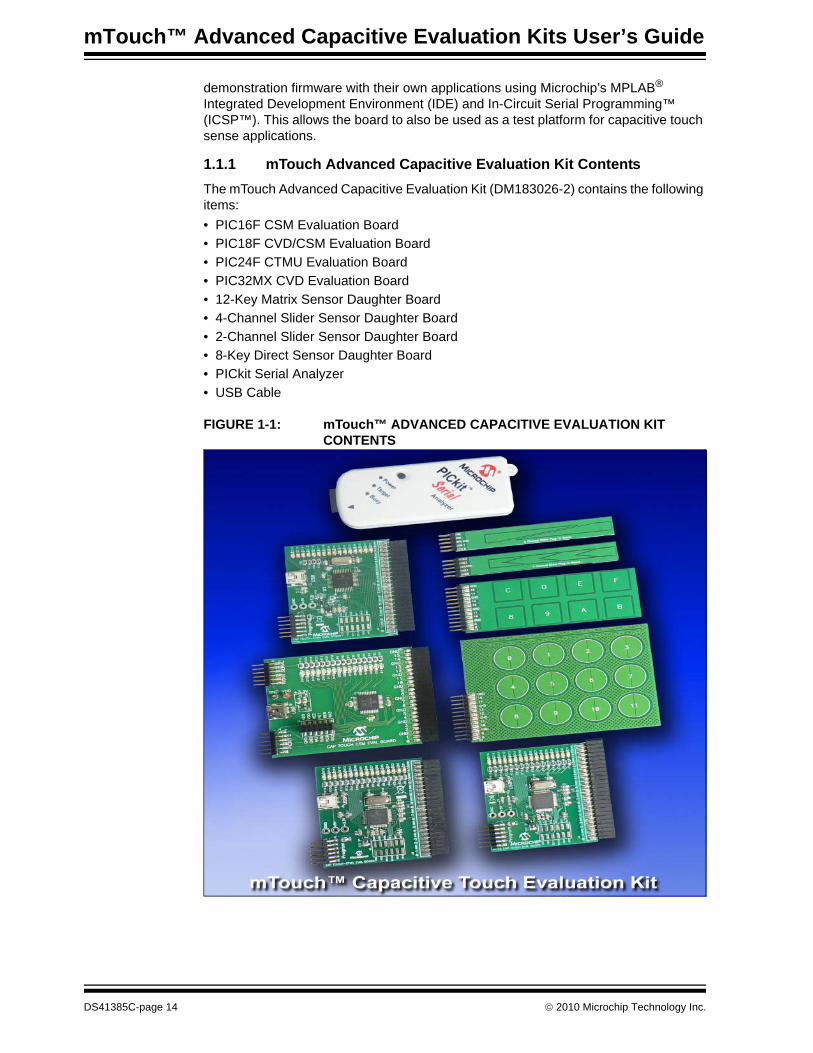
1.1.1 mTouch Advanced Capacitive Evaluation Kit ContentsThe mTouch Advanced Capacitive Evaluation Kit (DM183026-2) contains the following items:• PIC16F CSM Evaluation Board• PIC18F CVD/CSM Evaluation Board• PIC24F CTMU Evaluation Board• PIC32MX CVD Evaluation Board• 12-Key Matrix Sensor Daughter Board• 4-Channel Slider Sensor Daughter Board• 2-Channel Slider Sensor Daughter Board• 8-Key Direct Sensor Daughter Board• PICkit Serial Analyzer• USB Cable
FIGURE 1-1: mTouch™ ADVANCED CAPACITIVE EVALUATION KIT CONTENTS
DS41385C-page 14 © 2010 Microchip Technology Inc.
Introduction to the Evaluation Boards
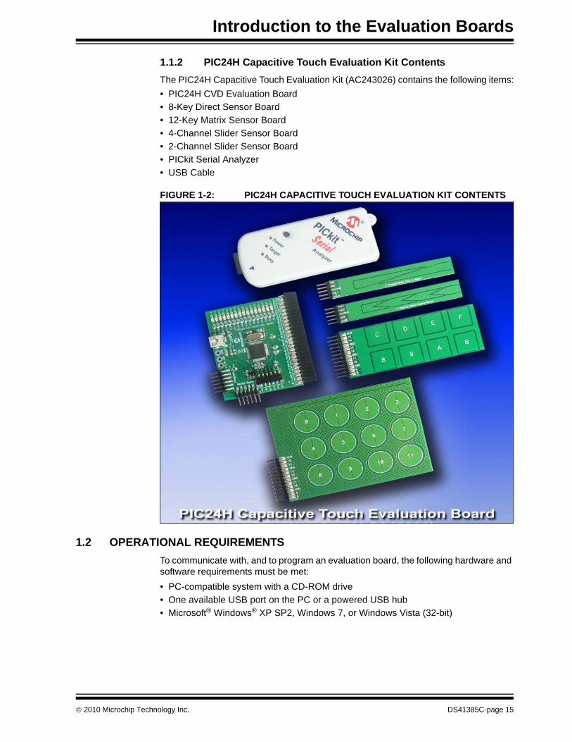
1.1.2 PIC24H Capacitive Touch Evaluation Kit ContentsThe PIC24H Capacitive Touch Evaluation Kit (AC243026) contains the following items:• PIC24H CVD Evaluation Board• 8-Key Direct Sensor Board• 12-Key Matrix Sensor Board• 4-Channel Slider Sensor Board• 2-Channel Slider Sensor Board• PICkit Serial Analyzer• USB Cable
FIGURE 1-2: PIC24H CAPACITIVE TOUCH EVALUATION KIT CONTENTS
1.2 OPERATIONAL REQUIREMENTSTo communicate with, and to program an evaluation board, the following hardware and software requirements must be met:• PC-compatible system with a CD-ROM drive• One available USB port on the PC or a powered USB hub• Microsoft® Windows® XP SP2, Windows 7, or Windows Vista (32-bit)
© 2010 Microchip Technology Inc. DS41385C-page 15
mTouch™ Advanced Capacitive Evaluation Kits User’s Guide
1.3 INITIAL BOARD SETUPWith its pre-installed demonstration application, the evaluation board is designed to be used straight out of the box. Except for a single connection to a computer, no additional hardware or configuration is necessary.
1.3.1 Installing the SoftwareBefore connecting the evaluation board to any computer for the first time, it is important to install the PC software found on the accompanying CD first. This ensures that the proper USB drivers for communicating with the evaluation board are installed and ready to recognize the board.To install the software and driver, insert the evaluation kit CD into the CD-ROM drive. The installation process starts automatically. The process pauses for user responses to accept the Microchip software licenses, and to confirm the installation directories; you must accept the license to use the software.
1.3.2 Connecting the HardwarePrior to connection, place the evaluation board on a flat surface near the computer. Check to make sure that there are no objects underneath the board. Once the evaluation kit software is installed, connect the provided USB cable (A to mini-B) to any available USB port on the PC or powered hub, and then to the board at the mini-B receptacle. The PC USB connection provides power to the board.The PIC24F and PIC18F CTMU and PIC32MX Capacitive Voltage Divider (CVD) evaluation boards use the USB connection to power up the boards and also to communicate with the mTouch diagnostic tool. The PIC16F Cap Sense Module (CSM) and PIC24H CVD evaluation boards use the PICkit Serial Analyzer to communicate to the PC. Connect the USB cable to the PICkit Serial Analyzer, and connect it to the J2 connector on the board and the PC’s USB port. The default code uses the 8-button board. When connecting the PIC24F and PIC18F CTMU and PIC32MX CVD boards, a sequence of pop-up messages should appear in the system tray (lower right of the desktop), stating that (1) new hardware has been found, (2) drivers are being installed and (3) the new hardware is ready for use. If you do not see these messages and the evaluation board does not work, try unplugging and reconnecting the USB cable. If this does not work, see Chapter 5. “Troubleshooting”.
DS41385C-page 16 © 2010 Microchip Technology Inc.
mTouch™ ADVANCED CAPACITIVEEVALUATION KITS USER’S GUIDE
Chapter 2. Demonstration Application
This chapter describes the touch sense application that is preprogrammed on the PIC16F, PIC18F, PIC24F, PIC24H and PIC32MX microcontrollers, and its general principles of operation. Topics included in this chapter are:• Introduction to the Touch Interface• Individual Touch Sense Demonstrations
2.1 INTRODUCTION TO THE TOUCH INTERFACEFor PIC24H and PIC32MX MCUs, touch sensing is achieved using a technique known as the Capacitive Voltage Divider, which makes use of the ADC module. This technique is based on successive charging/discharging cycles for sample and hold capacitance and conversely, sensor plus finger capacitance, which basically creates a voltage divider. For details, refer the application note, AN1298 “Capacitive Touch Using Only an ADC (“CVD”)” .Control of the touch sense features is built on the PIC18F and PIC24F microcontrollers’ on-chip Charge Time Measurement Unit (CTMU) module. The CTMU consists of a constant current source that charges each touch circuit to a voltage level. When any additional capacitance is added to the circuit (from the touch of a fingertip, for example), the fixed current source will now charge the circuit to a lower voltage. This change is how the microcontroller detects a touch event. For detailed information on the CTMU module, please refer to the related “Charge Time Measurement Unit (CTMU)” Family Reference Manual sections, which are available from the Microchip web site.On the PIC16F CSM Evaluation Board, the on-chip Cap Sense Module (CSM) creates a relaxation oscillator to perform touch sensing. The period or frequency of the relax-ation oscillator can be measured, and when the sensor is touched, the frequency will drop and the period will increase, indicating a touched condition.The microcontrollers use the CTMU, CVD or CSM to monitor its input channels, which are in turn, connected to capacitive touch pad sensors on the top layer of the circuit board.The evaluation board has four different sensor demonstration boards:• 8-Key Direct Plug-in Daughter Board• 12-Key Matrix Plug-in Daughter Board• 2-Channel Slider Plug-in Daughter Board• 4-Channel Slider Plug-in Daughter BoardA more detailed description of the evaluation boards’ operation is provided in Chapter 4. “Evaluation Board Hardware”.
2.1.1 Touch Sensitivity The response of the sensor to fingertip touch is influenced by many factors: touch areas, voltage and current levels, ambient humidity, static buildup, and so on. The capacitive touch sensing is done by a relative shift in the capacitance due to the addi-tion of the finger capacitance to the touch sensor. The demonstration code supplied takes most of the typical environmental factors into consideration. The demonstration application is very flexible in the sense that it can be modified by the user.
© 2010 Microchip Technology Inc. DS41385C-page 17
mTouch™ Advanced Capacitive Evaluation Kits User’s Guide
The PC-side application accompanying the mTouch Advanced Capacitive Evaluation Kit can be used to change the sensitivity of the sensors by writing trip point information back to the board.
2.1.2 Sensor PersistenceBy design, the demonstration application is designed to respond to a state change event on any sensor. More simply, they respond to a touch, and not to a touch and release. This behavior, along with the firmware’s slow averaging algorithm that accounts for constant changes in the evaluation board’s environment, causes a continuous touch on one or more sensors to yield an affirmative response for a few seconds, followed eventually by no response at all. Removing the touch stimulus from the sensor resets the algorithm and restores the sensor’s responsiveness.
2.2 INDIVIDUAL TOUCH SENSE DEMONSTRATIONS
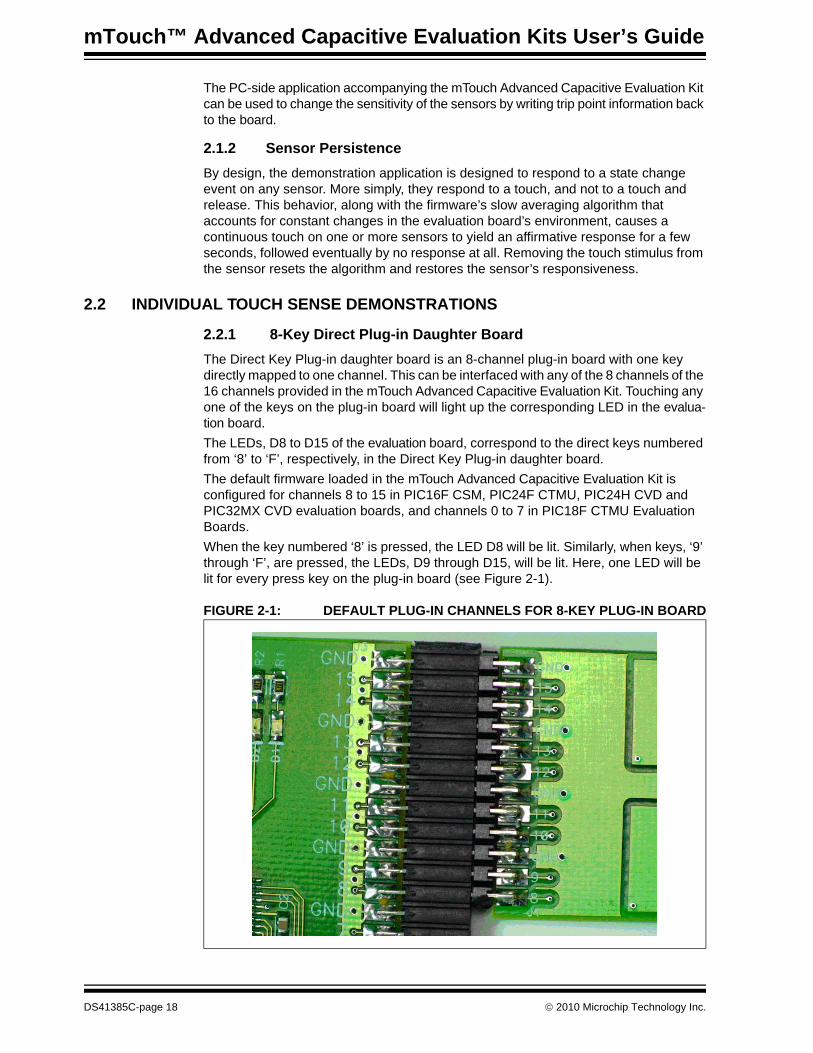
2.2.1 8-Key Direct Plug-in Daughter BoardThe Direct Key Plug-in daughter board is an 8-channel plug-in board with one key directly mapped to one channel. This can be interfaced with any of the 8 channels of the 16 channels provided in the mTouch Advanced Capacitive Evaluation Kit. Touching any one of the keys on the plug-in board will light up the corresponding LED in the evalua-tion board.The LEDs, D8 to D15 of the evaluation board, correspond to the direct keys numbered from ‘8’ to ‘F’, respectively, in the Direct Key Plug-in daughter board.The default firmware loaded in the mTouch Advanced Capacitive Evaluation Kit is configured for channels 8 to 15 in PIC16F CSM, PIC24F CTMU, PIC24H CVD and PIC32MX CVD evaluation boards, and channels 0 to 7 in PIC18F CTMU Evaluation Boards.When the key numbered ‘8’ is pressed, the LED D8 will be lit. Similarly, when keys, ‘9’ through ‘F’, are pressed, the LEDs, D9 through D15, will be lit. Here, one LED will be lit for every press key on the plug-in board (see Figure 2-1).
FIGURE 2-1: DEFAULT PLUG-IN CHANNELS FOR 8-KEY PLUG-IN BOARD
DS41385C-page 18 © 2010 Microchip Technology Inc.

Demonstration Application
2.2.2 12-Key Matrix Plug-in Daughter BoardThe Matrix Key Plug-in daughter board is an array of 12 touch-sensitive keys arranged in a 4x3 matrix. Touching any one of the keys will light up one of the LEDs. Here, the Matrix Key Plug-in daughter board is numbered, 0 to 11, which corresponds to LEDs D1 to D12, respectively.The default firmware loaded in the mTouch Advanced Capacitive Evaluation Kit for the Matrix Key Plug-in daughter board is configured for channels 8 to 14 in PIC16F CSM, PIC24F CTMU, PIC24H CVD and PIC32MX CVD evaluation boards, and channels 6 to 12 in PIC18F CTMU evaluation boards.When the key numbered ‘0’ is pressed, the LED D1 will be lit. Similarly, when the keys numbered ‘1’ to ‘11’ are pressed, the LEDs D2 through D12 will be lit, respectively. Here, one LED will be lit for every press of the key on the plug-in board.
2.2.3 2-Channel and 4-Channel Slider Plug-in Daughter BoardTouching anywhere along the length of the slider causes all the LEDs to light up as a bar graph that is representative to the position of the touch. The LED bar graph follows the finger as it moves up and down along the length of the slider, and remains at the last position on the slider when the finger is removed.The default firmware for the 2-Channel Slider Plug-in, loaded in the evaluation kit, is configured such that, the channels 0 and 1 of connector J4/J3 in the evaluation kit are connected to the 2-Channel Slider Plug-in daughter board.The default firmware for the 4-Channel Slider Plug-in, loaded in the evaluation kit, is configured such that, channels 0, 1, 2 and 3 of connector J4/J3 in the main evaluation board are connected to the 4 channels in the 4-Channel Slider Plug-in daughter board (see Figure 2-2).
FIGURE 2-2: DEFAULT PLUG-IN CHANNELS FOR 4-CHANNEL SLIDER PLUG-IN BOARD
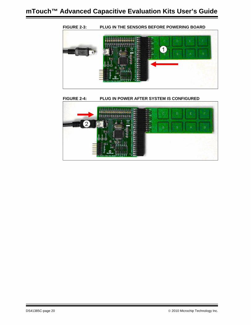
Note 1: The plug-in boards can be interfaced to any of the channels in the evaluation kit by changing the configuration settings. The details of the configuration settings are explained in the Readme.txt file, which is distributed in each demonstration.
2: Plugging a sensor board in while an evaluation board is running, may require resetting the touch algorithm, most easily done by cycling power.
© 2010 Microchip Technology Inc. DS41385C-page 19
mTouch™ Advanced Capacitive Evaluation Kits User’s Guide
FIGURE 2-3: PLUG IN THE SENSORS BEFORE POWERING BOARD
FIGURE 2-4: PLUG IN POWER AFTER SYSTEM IS CONFIGURED
DS41385C-page 20 © 2010 Microchip Technology Inc.
mTouch™ ADVANCED CAPACITIVEEVALUATION KITS USER’S GUIDE
Chapter 3. Using the mTouch™ Sensing Solution
This chapter describes the Graphical User Interface (GUI) diagnostic tool, mTouch™ sensing solution, that accompanies the evaluation boards in the mTouch Capacitive Evaluation Kits, and how it can be used in developing and troubleshooting touch sense applications. Topics include:• About the mTouch Sensing Solution Diagnostic Tool• MPLAB IDE integrated mTouch Diagnostic Tool GUI
3.1 ABOUT THE mTouch SENSING SOLUTION DIAGNOSTIC TOOLThe touch sensing solution is a multi-purpose application that has been designed for use with many of Microchip’s touch sense demonstrations. The software provides a useful tool for viewing, adjusting and debugging various aspects of the demonstration software preloaded on the evaluation boards. The touch sensing solution can also be used for developing customized applications.Initially the diagostic tool was developed as a standalone GUI and lately it is integrated into the MPLAB IDE. The latest version integrated with MPLAB IDE is backward compatible with the standalone GUI so that older embedded firmware can be run successfully. Note that, some of the additional enhancements may constraint the newer embedded firmware developed in conjunction with the latest GUI integrated with MPLAB IDE from correct functioning on the older standalone GUI.The following sections describes the MPLAB IDE integrated mTouch Diagonistic Tool GUI. These sections also list the embedded firmware that are successfully tested on this platform. The operation of the touch sensing solution described here is specific to its use with the evaluation boards. For use with other Microchip applications, refer to the specific application’s user’s guide.
3.2 MPLAB IDE INTEGRATED mTOUCH DIAGNOSTIC TOOL GUIThis section describes the MPLAB IDE integrated mTouch Diagnostic Tool GUI features.The following firmware items from the mTouch Advanced Capacitive Evaluation Kit (DM183026) were tested using this GUI:• PIC16F CSM Evaluation Board• PIC18F CTMU Evaluation Board• PIC24F CTMU Evaluation Board• PIC32MX CVD Evaluation BoardThe firmware for PIC24H CVD Evaluation Board was also tested using this GUI.
3.2.1 USING THE MPLAB IDE INTEGRATED mTOUCH DIAGNOSTIC TOOL GUI
Before starting the mTouch sensing solution diagnostic tool, ensure that the evaluation board is connected to a USB port on a personal computer (or a USB hub connected to the computer) and that the evaluation board is operating normally.
© 2010 Microchip Technology Inc. DS41385C-page 21
mTouch™ Advanced Capacitive Evaluation Kits User’s Guide
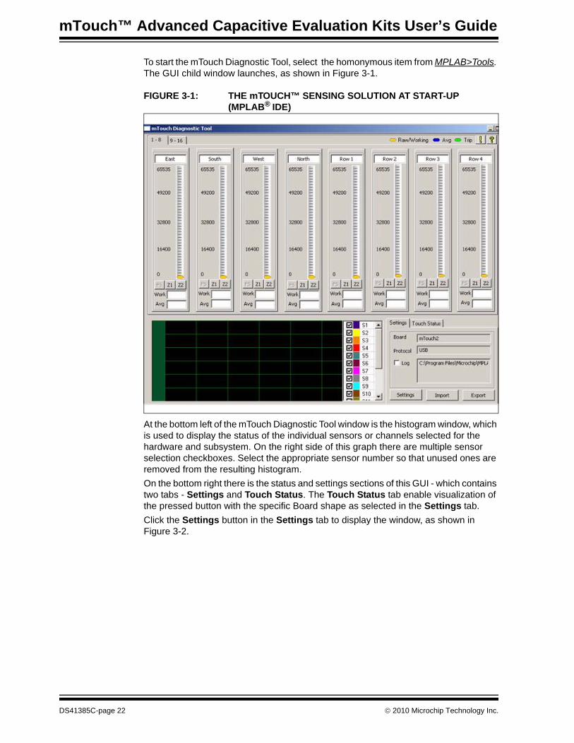
To start the mTouch Diagnostic Tool, select the homonymous item from MPLAB>Tools. The GUI child window launches, as shown in Figure 3-1.
FIGURE 3-1: THE mTOUCH™ SENSING SOLUTION AT START-UP (MPLAB® IDE)
At the bottom left of the mTouch Diagnostic Tool window is the histogram window, which is used to display the status of the individual sensors or channels selected for the hardware and subsystem. On the right side of this graph there are multiple sensor selection checkboxes. Select the appropriate sensor number so that unused ones are removed from the resulting histogram.On the bottom right there is the status and settings sections of this GUI - which contains two tabs - Settings and Touch Status. The Touch Status tab enable visualization of the pressed button with the specific Board shape as selected in the Settings tab.Click the Settings button in the Settings tab to display the window, as shown in Figure 3-2.
DS41385C-page 22 © 2010 Microchip Technology Inc.
Using the mTouch™ Sensing Solution
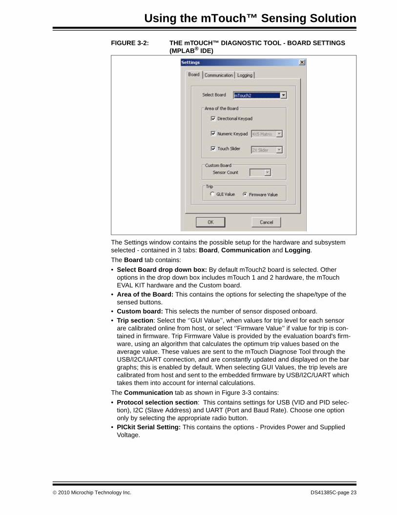
FIGURE 3-2: THE mTOUCH™ DIAGNOSTIC TOOL - BOARD SETTINGS (MPLAB® IDE)
The Settings window contains the possible setup for the hardware and subsystem selected - contained in 3 tabs: Board, Communication and Logging. The Board tab contains: • Select Board drop down box: By default mTouch2 board is selected. Other
options in the drop down box includes mTouch 1 and 2 hardware, the mTouch EVAL KIT hardware and the Custom board.
• Area of the Board: This contains the options for selecting the shape/type of the sensed buttons.
• Custom board: This selects the number of sensor disposed onboard.• Trip section: Select the ‘’GUI Value’’, when values for trip level for each sensor
are calibrated online from host, or select ‘’Firmware Value’’ if value for trip is con-tained in firmware. Trip Firmware Value is provided by the evaluation board's firm-ware, using an algorithm that calculates the optimum trip values based on the average value. These values are sent to the mTouch Diagnose Tool through the USB/I2C/UART connection, and are constantly updated and displayed on the bar graphs; this is enabled by default. When selecting GUI Values, the trip levels are calibrated from host and sent to the embedded firmware by USB/I2C/UART which takes them into account for internal calculations.
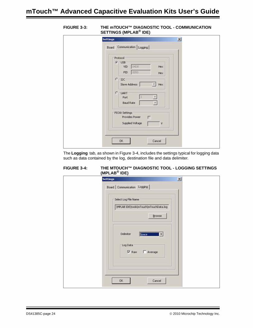
The Communication tab as shown in Figure 3-3 contains:• Protocol selection section: This contains settings for USB (VID and PID selec-
tion), I2C (Slave Address) and UART (Port and Baud Rate). Choose one option only by selecting the appropriate radio button.
• PICkit Serial Setting: This contains the options - Provides Power and Supplied Voltage.
© 2010 Microchip Technology Inc. DS41385C-page 23
mTouch™ Advanced Capacitive Evaluation Kits User’s Guide
FIGURE 3-3: THE mTOUCH™ DIAGNOSTIC TOOL - COMMUNICATION SETTINGS (MPLAB® IDE)
The Logging tab, as shown in Figure 3-4, includes the settings typical for logging data such as data contained by the log, destination file and data delimiter.
FIGURE 3-4: THE MTOUCH™ DIAGNOSTIC TOOL - LOGGING SETTINGS (MPLAB® IDE)
DS41385C-page 24 © 2010 Microchip Technology Inc.
Using the mTouch™ Sensing Solution
Click OK to close the Settings window and to display the setup in the Settings tab. To actually use the logging, check the Log checkbox in the Settings tab (the setup made previously will be used for logging).The upper part of the mTouch Diagnostic Tool window contains the status display for each of the sensors in form of a bar graph. Above each bar graph display is an indicator; this lights up (changes to light green) when the software detects a touch event. The bar graph shows the sensor's current state in terms of the A/D conversion value of its channel. Values shown may be in the range of 0 to 65,535 and are dimensionless.Each bar graph has the following information:• A constantly moving orange vertical bar that indicates the instantaneous
conversion value• A blue horizontal indicator across the bar that indicates the moving average of the
touch sensor• A green horizontal indicator that shows the trip level that the touch channel must
reach to become pressed or activated• The average and raw conversion values, displayed numerically at the bottom of
the bar graphA color key for the indicators is provided at the top of the mTouch Diagnostic Tool window.The A/D converter produces values of up to 4096 (12 bits). The evaluation board contains software algorithms that use scaled values of the raw A/D reading to improve averaging and overall performance of the hardware.Right click on the bar graph for each sensor to display menu options: Display Data, Zoom Settings and Sensor Settings.
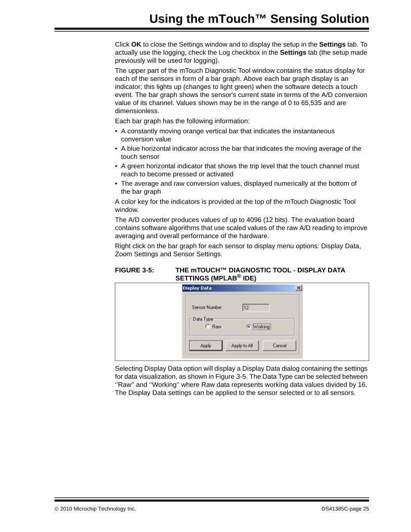
FIGURE 3-5: THE mTOUCH™ DIAGNOSTIC TOOL - DISPLAY DATA SETTINGS (MPLAB® IDE)
Selecting Display Data option will display a Display Data dialog containing the settings for data visualization, as shown in Figure 3-5. The Data Type can be selected between ‘’Raw’’ and ‘’Working’’ where Raw data represents working data values divided by 16. The Display Data settings can be applied to the sensor selected or to all sensors.
© 2010 Microchip Technology Inc. DS41385C-page 25
mTouch™ Advanced Capacitive Evaluation Kits User’s Guide
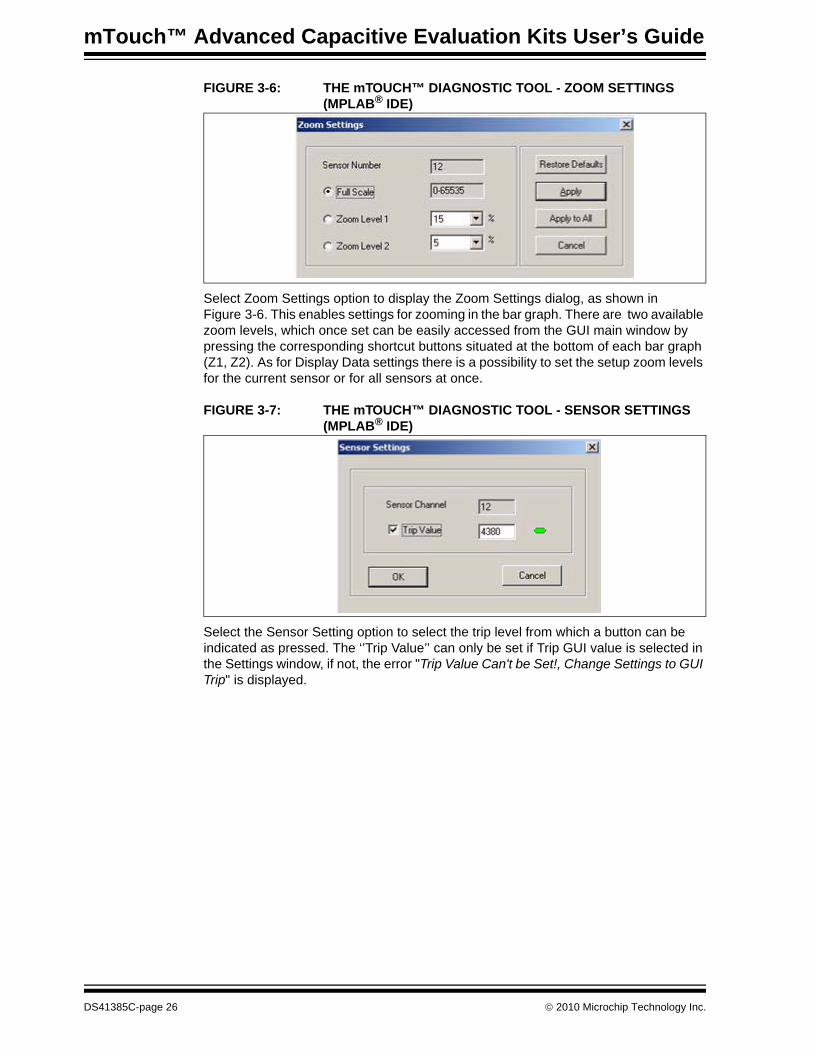
FIGURE 3-6: THE mTOUCH™ DIAGNOSTIC TOOL - ZOOM SETTINGS (MPLAB® IDE)
Select Zoom Settings option to display the Zoom Settings dialog, as shown in Figure 3-6. This enables settings for zooming in the bar graph. There are two available zoom levels, which once set can be easily accessed from the GUI main window by pressing the corresponding shortcut buttons situated at the bottom of each bar graph (Z1, Z2). As for Display Data settings there is a possibility to set the setup zoom levels for the current sensor or for all sensors at once.
FIGURE 3-7: THE mTOUCH™ DIAGNOSTIC TOOL - SENSOR SETTINGS (MPLAB® IDE)
Select the Sensor Setting option to select the trip level from which a button can be indicated as pressed. The ‘’Trip Value’’ can only be set if Trip GUI value is selected in the Settings window, if not, the error "Trip Value Can't be Set!, Change Settings to GUI Trip" is displayed.
DS41385C-page 26 © 2010 Microchip Technology Inc.
mTouch™ ADVANCED CAPACITIVEEVALUATION KITS USER’S GUIDE
Chapter 4. Evaluation Board Hardware
This chapter provides a functional overview of the evaluation boards and identifies the major hardware components. Topics covered include:• Application Functional Overview• Board Components
4.1 APPLICATION FUNCTIONAL OVERVIEW
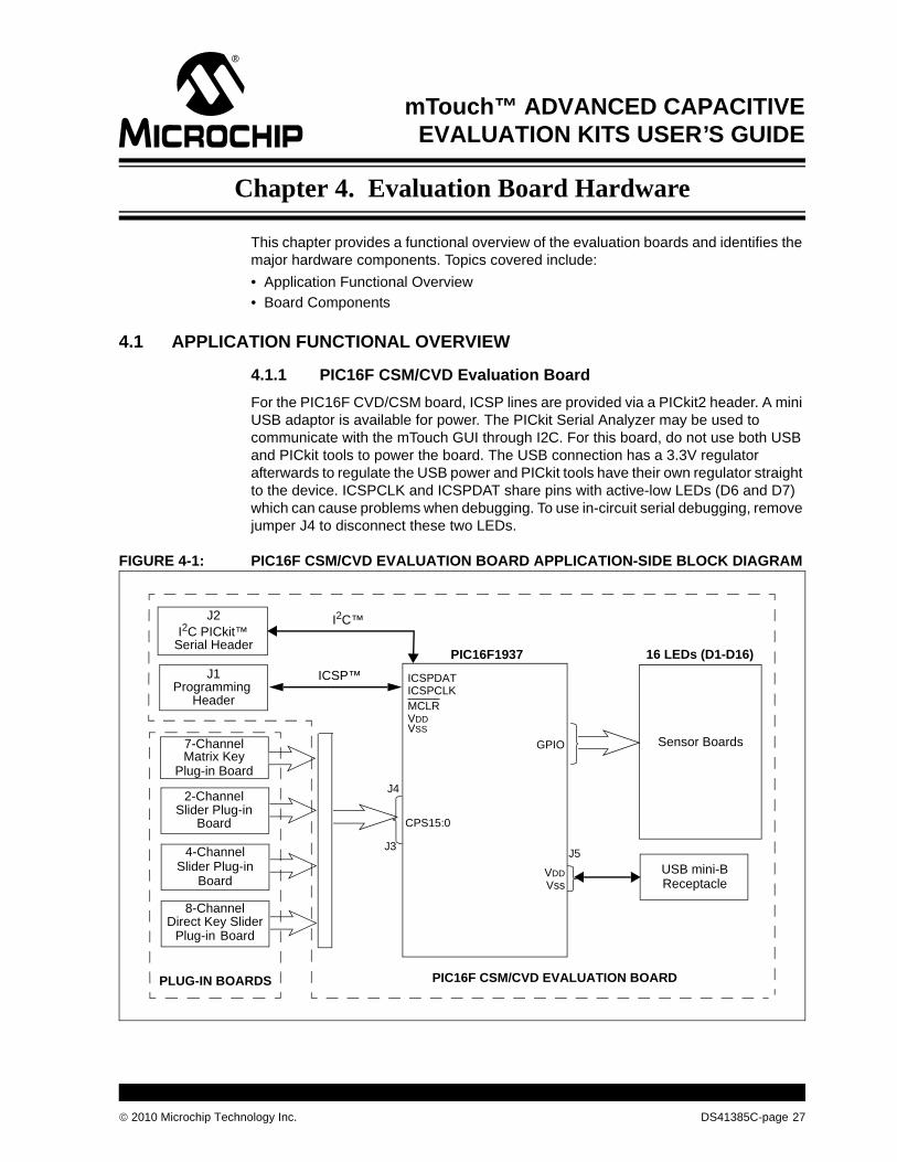
4.1.1 PIC16F CSM/CVD Evaluation BoardFor the PIC16F CVD/CSM board, ICSP lines are provided via a PICkit2 header. A mini USB adaptor is available for power. The PICkit Serial Analyzer may be used to communicate with the mTouch GUI through I2C. For this board, do not use both USB and PICkit tools to power the board. The USB connection has a 3.3V regulator afterwards to regulate the USB power and PICkit tools have their own regulator straight to the device. ICSPCLK and ICSPDAT share pins with active-low LEDs (D6 and D7) which can cause problems when debugging. To use in-circuit serial debugging, remove jumper J4 to disconnect these two LEDs.
FIGURE 4-1: PIC16F CSM/CVD EVALUATION BOARD APPLICATION-SIDE BLOCK DIAGRAM
PIC16F1937
USB mini-BReceptacle
Matrix Key
ICSP™
VDD
ICSPDATICSPCLKMCLR
7-Channel
J1Programming
Header
CPS15:0
4-Channel
Slider Plug-in
Direct Key Slider8-Channel
J42-Channel
16 LEDs (D1-D16)
Sensor Boards
Board
Plug-in Board
Slider Plug-inBoard
BoardPlug-in
J5
PLUG-IN BOARDS PIC16F CSM/CVD EVALUATION BOARD
J2
Serial HeaderI2C PICkit™
I2C™
VDDVSS
GPIO
Vss
J3
© 2010 Microchip Technology Inc. DS41385C-page 27
mTouch™ Advanced Capacitive Evaluation Kits User’s Guide
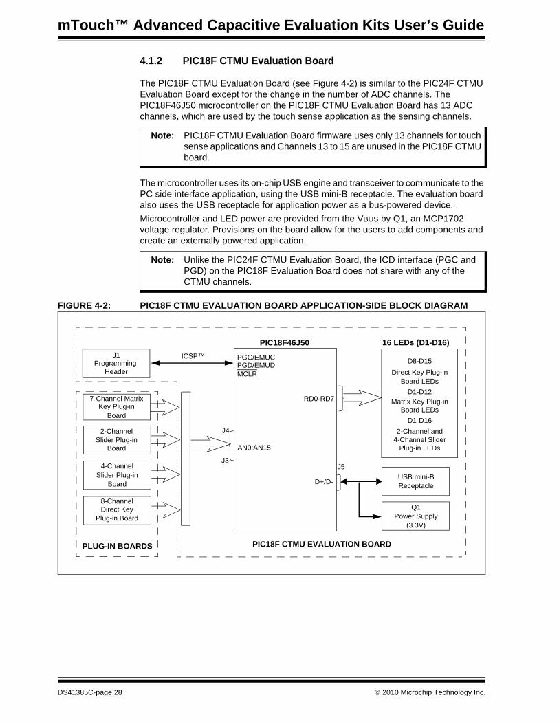
4.1.2 PIC18F CTMU Evaluation Board
The PIC18F CTMU Evaluation Board (see Figure 4-2) is similar to the PIC24F CTMU Evaluation Board except for the change in the number of ADC channels. The PIC18F46J50 microcontroller on the PIC18F CTMU Evaluation Board has 13 ADC channels, which are used by the touch sense application as the sensing channels.
The microcontroller uses its on-chip USB engine and transceiver to communicate to the PC side interface application, using the USB mini-B receptacle. The evaluation board also uses the USB receptacle for application power as a bus-powered device.Microcontroller and LED power are provided from the VBUS by Q1, an MCP1702 voltage regulator. Provisions on the board allow for the users to add components and create an externally powered application.
FIGURE 4-2: PIC18F CTMU EVALUATION BOARD APPLICATION-SIDE BLOCK DIAGRAM
Note: PIC18F CTMU Evaluation Board firmware uses only 13 channels for touch sense applications and Channels 13 to 15 are unused in the PIC18F CTMU board.
Note: Unlike the PIC24F CTMU Evaluation Board, the ICD interface (PGC and PGD) on the PIC18F Evaluation Board does not share with any of the CTMU channels.
PIC18F46J50
USB mini-BReceptacle
Key Plug-in
ICSP™
D+/D-
PGC/EMUCPGD/EMUDMCLR
7-Channel Matrix
J1Programming
Header
AN0:AN15
4-Channel
Slider Plug-in
Power SupplyQ1
RD0-RD7
Direct Key8-Channel
J42-Channel
16 LEDs (D1-D16)
D8-D15Direct Key Plug-in
D1-D12Matrix Key Plug-in
D1-D162-Channel and
4-Channel SliderPlug-in LEDsBoard
Board
Slider Plug-inBoard
Plug-in Board
Board LEDs
Board LEDs
(3.3V)
J5
PLUG-IN BOARDS PIC18F CTMU EVALUATION BOARD
J3
DS41385C-page 28 © 2010 Microchip Technology Inc.
Evaluation Board Hardware
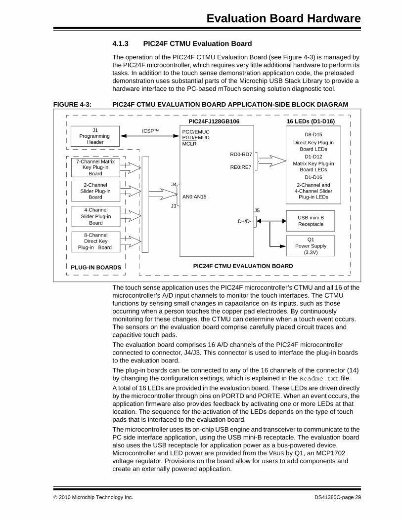
4.1.3 PIC24F CTMU Evaluation Board
The operation of the PIC24F CTMU Evaluation Board (see Figure 4-3) is managed by the PIC24F microcontroller, which requires very little additional hardware to perform its tasks. In addition to the touch sense demonstration application code, the preloaded demonstration uses substantial parts of the Microchip USB Stack Library to provide a hardware interface to the PC-based mTouch sensing solution diagnostic tool.
FIGURE 4-3: PIC24F CTMU EVALUATION BOARD APPLICATION-SIDE BLOCK DIAGRAM
The touch sense application uses the PIC24F microcontroller’s CTMU and all 16 of the microcontroller’s A/D input channels to monitor the touch interfaces. The CTMU functions by sensing small changes in capacitance on its inputs, such as those occurring when a person touches the copper pad electrodes. By continuously monitoring for these changes, the CTMU can determine when a touch event occurs. The sensors on the evaluation board comprise carefully placed circuit traces and capacitive touch pads.The evaluation board comprises 16 A/D channels of the PIC24F microcontroller connected to connector, J4/J3. This connector is used to interface the plug-in boards to the evaluation board.The plug-in boards can be connected to any of the 16 channels of the connector (14) by changing the configuration settings, which is explained in the Readme.txt file.A total of 16 LEDs are provided in the evaluation board. These LEDs are driven directly by the microcontroller through pins on PORTD and PORTE. When an event occurs, the application firmware also provides feedback by activating one or more LEDs at that location. The sequence for the activation of the LEDs depends on the type of touch pads that is interfaced to the evaluation board. The microcontroller uses its on-chip USB engine and transceiver to communicate to the PC side interface application, using the USB mini-B receptacle. The evaluation board also uses the USB receptacle for application power as a bus-powered device. Microcontroller and LED power are provided from the VBUS by Q1, an MCP1702 voltage regulator. Provisions on the board allow for users to add components and create an externally powered application.
PIC24FJ128GB106
USB mini-BReceptacle
Key Plug-in
ICSP™
D+/D-
PGC/EMUCPGD/EMUDMCLR
7-Channel Matrix
J1Programming
Header
AN0:AN15
4-Channel
Slider Plug-in
Power SupplyQ1
RE0:RE7
RD0-RD7
Direct Key8-Channel
J42-Channel
16 LEDs (D1-D16)
D8-D15Direct Key Plug-in
D1-D12Matrix Key Plug-in
D1-D162-Channel and
4-Channel SliderPlug-in LEDsBoard
Board
Slider Plug-inBoard
BoardPlug-in
Board LEDs
Board LEDs
(3.3V)
J5
PLUG-IN BOARDS PIC24F CTMU EVALUATION BOARD
J3
© 2010 Microchip Technology Inc. DS41385C-page 29
mTouch™ Advanced Capacitive Evaluation Kits User’s Guide
For users interested in using the evaluation board as an experimental platform, the microcontroller can be reprogrammed using the ICSP connector. A 6-pin header is provided for connecting the evaluation board to any MPLAB ICD 2 compatible programmer. Since the ICD interface (PGD and PGC) shares some input channels of the connector, J4/J3 (channel 6 and 7), necessary care should be taken when the debugger is enabled.The firmware in the evaluation board will have the default plug-in board channel configurations, which is explained in the Readme.txt file. The user can reconfigure the channels based on his application by referring to the Readme.txt file.
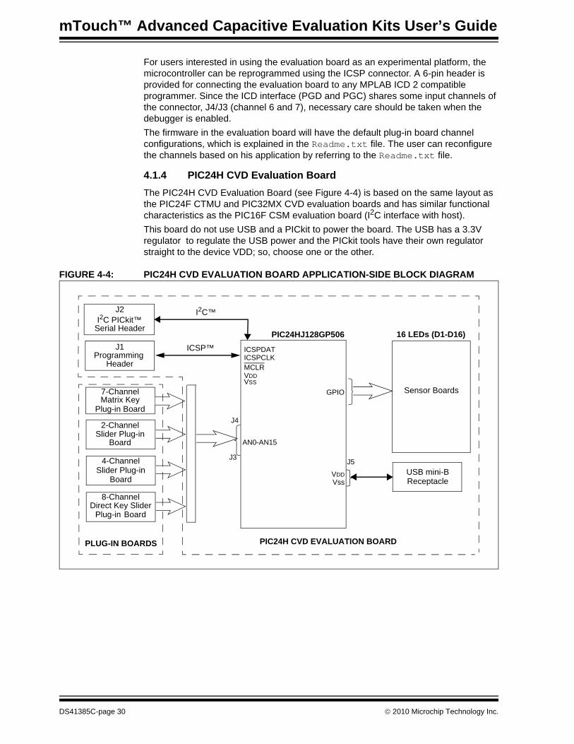
4.1.4 PIC24H CVD Evaluation BoardThe PIC24H CVD Evaluation Board (see Figure 4-4) is based on the same layout as the PIC24F CTMU and PIC32MX CVD evaluation boards and has similar functional characteristics as the PIC16F CSM evaluation board (I2C interface with host).This board do not use USB and a PICkit to power the board. The USB has a 3.3V regulator to regulate the USB power and the PICkit tools have their own regulator straight to the device VDD; so, choose one or the other.
FIGURE 4-4: PIC24H CVD EVALUATION BOARD APPLICATION-SIDE BLOCK DIAGRAM
PIC24HJ128GP506
USB mini-BReceptacle
Matrix Key
ICSP™
VDD
ICSPDATICSPCLKMCLR
7-Channel
J1Programming
Header
AN0-AN15
4-Channel
Slider Plug-in
Direct Key Slider8-Channel
J42-Channel
16 LEDs (D1-D16)
Sensor Boards
Board
Plug-in Board
Slider Plug-inBoard
BoardPlug-in
J5
PLUG-IN BOARDS PIC24H CVD EVALUATION BOARD
J2
Serial HeaderI2C PICkit™
I2C™
VDDVSS
GPIO
Vss
J3
DS41385C-page 30 © 2010 Microchip Technology Inc.
Evaluation Board Hardware
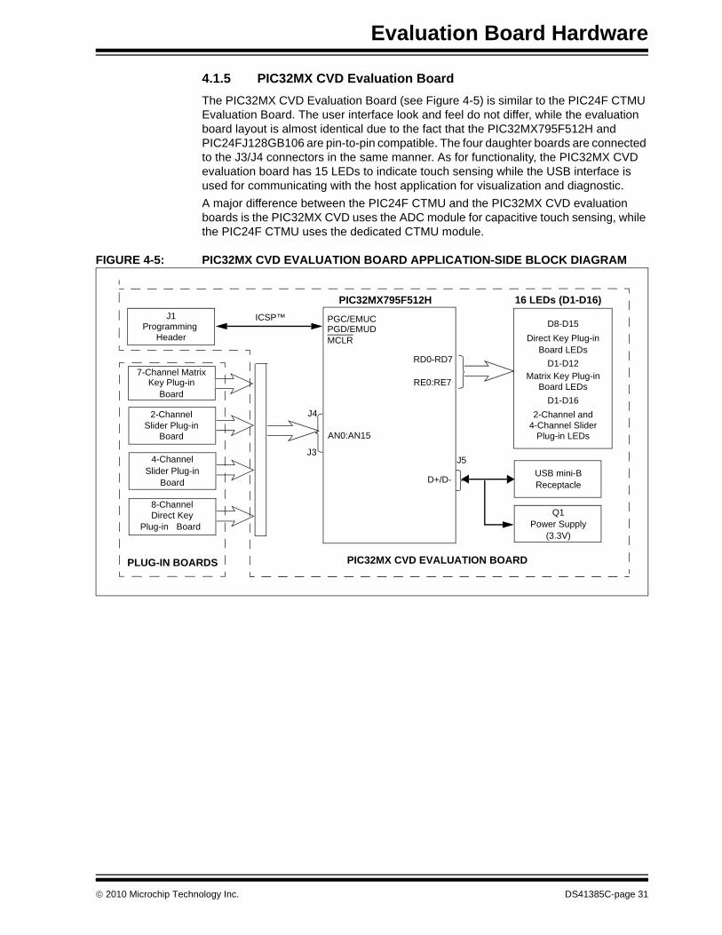
4.1.5 PIC32MX CVD Evaluation BoardThe PIC32MX CVD Evaluation Board (see Figure 4-5) is similar to the PIC24F CTMU Evaluation Board. The user interface look and feel do not differ, while the evaluation board layout is almost identical due to the fact that the PIC32MX795F512H and PIC24FJ128GB106 are pin-to-pin compatible. The four daughter boards are connected to the J3/J4 connectors in the same manner. As for functionality, the PIC32MX CVD evaluation board has 15 LEDs to indicate touch sensing while the USB interface is used for communicating with the host application for visualization and diagnostic.A major difference between the PIC24F CTMU and the PIC32MX CVD evaluation boards is the PIC32MX CVD uses the ADC module for capacitive touch sensing, while the PIC24F CTMU uses the dedicated CTMU module.
FIGURE 4-5: PIC32MX CVD EVALUATION BOARD APPLICATION-SIDE BLOCK DIAGRAM
PIC32MX795F512H
USB mini-BReceptacle
Key Plug-in
ICSP™
D+/D-
PGC/EMUCPGD/EMUDMCLR
7-Channel Matrix
J1Programming
Header
AN0:AN15
4-Channel
Slider Plug-in
Power SupplyQ1
RE0:RE7
RD0-RD7
Direct Key8-Channel
J42-Channel
16 LEDs (D1-D16)
D8-D15Direct Key Plug-in
D1-D12Matrix Key Plug-in
D1-D162-Channel and
4-Channel SliderPlug-in LEDsBoard
Board
Slider Plug-inBoard
BoardPlug-in
Board LEDs
Board LEDs
(3.3V)
J5
PLUG-IN BOARDS PIC32MX CVD EVALUATION BOARD
J3
© 2010 Microchip Technology Inc. DS41385C-page 31

mTouch™ Advanced Capacitive Evaluation Kits User’s Guide
4.2 BOARD COMPONENTS
4.2.1 PIC16F CSM/CVD Evaluation BoardFigure 4-6 identifies the key hardware components that are common for the PIC16F CSM/CVD evaluation board. There is one evaluation board and four plug-in daughter boards. The four plug-in daughter boards are identified as direct keys, matrix keys, 2-channel slider and 4-channel slider.
FIGURE 4-6: PIC16F CSM/CVD EVALUATION BOARD COMPONENT LAYOUT (TOP SIDE)
TABLE 4-1: BOARD COMPONENTSReference Component
1 PIC16F1937 Microcontroller (U1) for PIC16F CSM Board2 USB mini-B Receptacle (J5)3 ICSP™ Programming Header (J1)4 Power Supply (U2) to provide the VDD to the Evaluation Board5 Plug-in Sensor LEDs (D1-D16)6 Plug-in Interface Connector (J4/J3)7 PICkit serial analyzer connector
1
57
4
2
3
6
DS41385C-page 32 © 2010 Microchip Technology Inc.

Evaluation Board Hardware
4.2.1.1 COMPONENT DESCRIPTIONS
The components listed here (in order of their reference tags in Figure 4-6) are the key components of the application side of the PIC16F CSM Evaluation Board:1. PIC16F1937 Microcontroller (U1): This provides the processing power for the
touch sense applications in the PIC16F Evaluation Board. 2. USB mini-B Receptacle (J5): This provides power to the board via USB.3. ICSP™ Programming Header (J1): This provides a standard Microchip ICD
interface for programming and debugging applications on an evaluation board. It is designed to connect directly with Microchip's PICkit 3. Pin 1 is located on the right side of the interface, as viewed from the front of the board, and is marked with an arrow
4. PICkit Serial Analyzer connector (J2): This connector is used to exchange data to the Host PC through I2C using the PICkit Serial Analyzer.
5. Power Supply (Q1): This converts the +5 VDC from VBUS to the regulated+3.3 VDC required by the evaluation board.
6. Plug-in Sensor LEDs (D1-D16): Sixteen LEDs (D1 through D16) are connected to one general purpose I/O ports of the PIC microcontroller. These LEDs are lit based on the need of the application.
7. Plug-in Interface Connector (J4/J3): This is a 48-pin connector, which is used to interface the different plug-in boards to the microcontroller. This connector is interfaced to 16 analog channels of the microcontroller and the remaining pins are connected to ground of the evaluation board.
4.2.2 PIC18F CTMU, PIC24F CTMU, and PIC32MX CVD Evaluation Boards
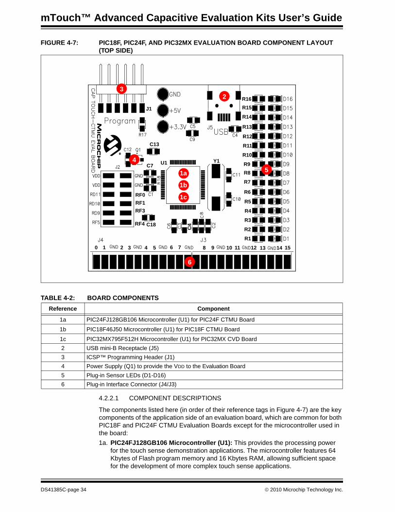
Figure 4-7 identifies the key hardware components that are common for the PIC18F CTMU, PIC24F CTMU, and PIC32MX CVD evaluation boards. There is one evaluation board and four plug-in daughter boards. The four plug-in daughter boards are identified as direct keys, matrix keys, 2-channel slider and 4-channel slider.
© 2010 Microchip Technology Inc. DS41385C-page 33
mTouch™ Advanced Capacitive Evaluation Kits User’s Guide
FIGURE 4-7: PIC18F, PIC24F, AND PIC32MX EVALUATION BOARD COMPONENT LAYOUT (TOP SIDE)
TABLE 4-2: BOARD COMPONENTS
4.2.2.1 COMPONENT DESCRIPTIONS
The components listed here (in order of their reference tags in Figure 4-7) are the key components of the application side of an evaluation board, which are common for both PIC18F and PIC24F CTMU Evaluation Boards except for the microcontroller used in the board:1a. PIC24FJ128GB106 Microcontroller (U1): This provides the processing power
for the touch sense demonstration applications. The microcontroller features 64 Kbytes of Flash program memory and 16 Kbytes RAM, allowing sufficient space for the development of more complex touch sense applications.
Reference Component
1a PIC24FJ128GB106 Microcontroller (U1) for PIC24F CTMU Board
1b PIC18F46J50 Microcontroller (U1) for PIC18F CTMU Board
1c PIC32MX795F512H Microcontroller (U1) for PIC32MX CVD Board2 USB mini-B Receptacle (J5)3 ICSP™ Programming Header (J1)4 Power Supply (Q1) to provide the VDD to the Evaluation Board5 Plug-in Sensor LEDs (D1-D16)6 Plug-in Interface Connector (J4/J3)
J1
C13
C7 U1
R15R16
R14
R10
R13
R12
R11
R8R9
R7
R3
R6
R5
R4
R1
R2
Y1
C4
RF1RF3
RF4 C18
RF0
0 1 2 3 4 5 6 7 8 9 10 11 12 13 14 15
1a
2
5
6
4
3
1b
1c
DS41385C-page 34 © 2010 Microchip Technology Inc.

Evaluation Board Hardware
The demonstration application uses an 8 MHz signal to create the 48 MHz USB clock, as well as the application’s 32 MHz clock. Crystal, Y1, and associated components are used by the microcontroller’s internal oscillator to maintain the frequency tolerances required by the USB specifications.
1b. PIC18F46J50 Microcontroller (U1): This provides the processing power for the touch sense applications in the PIC18F Evaluation Board. The microcontroller features 64 Kbytes of Flash program memory and 3.8 Kbytes RAM. The demon-stration application uses an 8 MHz signal to create the 48 MHz USB clock, as well as the application’s 32 MHz clock. Crystal, Y1, and associated components are used by the microcontroller’s internal oscillator to maintain the frequency tolerances required by the USB specifications.
1c. PIC32MX795F512H Microcontroller (U1): This provides the processing power for the touch sense applications in the PIC32MX CVD Evaluation Board. The microcontroller features 512 Kbytes of Flash program memory and 128 Kbytes RAM. The demonstration application uses an 8 MHz signal to create the 48 MHz USB clock, as well as the application’s 40 MHz clock. Crystal, Y1, and associated components are used by the microcontroller’s internal oscillator to maintain the frequency tolerances required by the USB specifications.
2. USB mini-B Receptacle (J5): This provides a convenient interface to the PC side of the demonstration application. As the evaluation board functions as a bus-powered device, this connection also provides power to the board.
3. ICSP™ Programming Header (J1): This provides a standard Microchip ICD interface for programming and debugging applications on an evaluation board. It is designed to connect directly with Microchip’s PICkit™ Starter Kit. Pin 1 (N/C) is located on the right side of the interface, as viewed from the front of the board, and is marked with an arrow.
4. Power Supply (Q1): This converts the +5 VDC from VBUS to the regulated +3.3 VDC required by the evaluation board.
5. Plug-in Sensor LEDs (D1-D16): Sixteen LEDs (D1 through D16) are connected to PORTD and PORTE of the PIC® microcontroller. These LEDs are lit based on the need of the application.
6. Plug-in Interface Connector (J4/J3): This is a 48-pin connector, which is used to interface the different plug-in boards to the microcontroller. This connector is interfaced to 16 analog channels of the microcontroller and the remaining pins are connected to ground of the evaluation board.
© 2010 Microchip Technology Inc. DS41385C-page 35
mTouch™ Advanced Capacitive Evaluation Kits User’s Guide
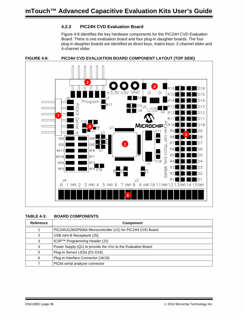
4.2.3 PIC24H CVD Evaluation BoardFigure 4-8 identifies the key hardware components for the PIC24H CVD Evaluation Board. There is one evaluation board and four plug-in daughter boards. The four plug-in daughter boards are identified as direct keys, matrix keys, 2-channel slider and 4-channel slider.
FIGURE 4-8: PIC24H CVD EVALUATION BOARD COMPONENT LAYOUT (TOP SIDE)
TABLE 4-3: BOARD COMPONENTSReference Component
1 PIC24HJ128GP506A Microcontroller (U1) for PIC24H CVD Board2 USB mini-B Receptacle (J5)3 ICSP™ Programming Header (J1)4 Power Supply (Q1) to provide the VDD to the Evaluation Board5 Plug-in Sensor LEDs (D1-D16)6 Plug-in Interface Connector (J4/J3)7 PICkit serial analyzer connector
32
7
5
4
1
6
DS41385C-page 36 © 2010 Microchip Technology Inc.

Evaluation Board Hardware
4.2.3.1 COMPONENT DESCRIPTIONS
The components listed here (in order of their reference tags in Figure 4-8) are the key components of the application side of the PIC24H CVD Evaluation Board:1. PIC24HJ128GP506A Microcontroller (U1): This provides the processing
power for the touch sense applications in the PIC24H Evaluation Board.2. USB mini-B Receptacle (J5): This provides power to the board via USB.3. ICSP™ Programming Header (J1): This provides a standard Microchip ICD
interface for programming and debugging applications on an evaluation board. It is designed to connect directly with Microchip's PICkit 3, REAL ICE or ICD 3. Pin 1 is located on the right side of the interface, as viewed from the front of the board, and is marked with an arrow.
4. PICkit Serial Analyzer connector (J2): This connector is used to exchange data to the Host PC through I2C using the PICkit Serial Analyzer.
5. Power Supply (Q1): This converts the +5 VDC from VBUS to the regulated+3.3 VDC required by the evaluation board.
6. Plug-in Sensor LEDs (D1-D16): Sixteen LEDs (D1 through D16) are connected to one general purpose I/O ports of the PIC microcontroller. These LEDs are lit based on the need of the application.
7. Plug-in Interface Connector (J4/J3): This is a 48-pin connector, which is used to interface the different plug-in boards to the microcontroller. This connector is interfaced to 16 analog channels of the microcontroller and the remaining pins are connected to ground of the evaluation board.
© 2010 Microchip Technology Inc. DS41385C-page 37
mTouch™ Advanced Capacitive Evaluation Kits User’s Guide
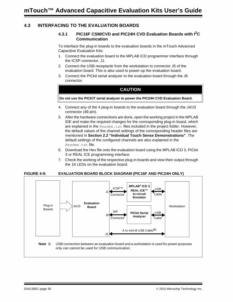
4.3 INTERFACING TO THE EVALUATION BOARDS
4.3.1 PIC16F CSM/CVD and PIC24H CVD Evaluation Boards with I2C Communication
To interface the plug-in boards to the evaluation boards in the mTouch Advanced Capacitive Evaluation Kits:1. Connect the evaluation board to the MPLAB ICD programmer interface through
the ICSP connector, J1.2. Connect the USB receptacle from the workstation to connector J5 of the
evaluation board. This is also used to power-up the evaluation board. 3. Connect the PICkit serial analyzer to the evaluation board through the J6
connector.
4. Connect any of the 4 plug-in boards to the evaluation board through the J4/J3 connector (48-pin).
5. After the hardware connections are done, open the working project in the MPLAB IDE and make the required changes for the corresponding plug-in board, which are explained in the Readme.txt files included in the project folder. However, the default values of the channel settings of the corresponding header files are mentioned in Section 2.2 “Individual Touch Sense Demonstrations”. The default settings of the configured channels are also explained in the Readme.txt file.
6. Download the Hex file onto the evaluation board using the MPLAB ICD 3, PICkit 3 or REAL ICE programming interface.
7. Check the working of the respective plug-in boards and view their output through the 16 LEDs on the evaluation board.
FIGURE 4-9: EVALUATION BOARD BLOCK DIAGRAM (PIC16F AND PIC24H ONLY)
CAUTION
Do not use the PICKIT serial analyzer to power the PIC24H CVD Evaluation Board.
Workstation
USB
Cable
MPLAB® ICD 3REAL ICE™
ICSP™
ConnectorJ1
EvaluationJ4/J3Plug-in
BoardsBoard
In-circuitEmulator
USB
Cable
SIP
ConnectorJ6
PICkit SerialAnalyzer
A to mini-B USB Cable(1)
J5
Note 1: USB connection between an evaluation board and a workstation is used for power purposes only can cannot be used for USB communication.
DS41385C-page 38 © 2010 Microchip Technology Inc.
Evaluation Board Hardware
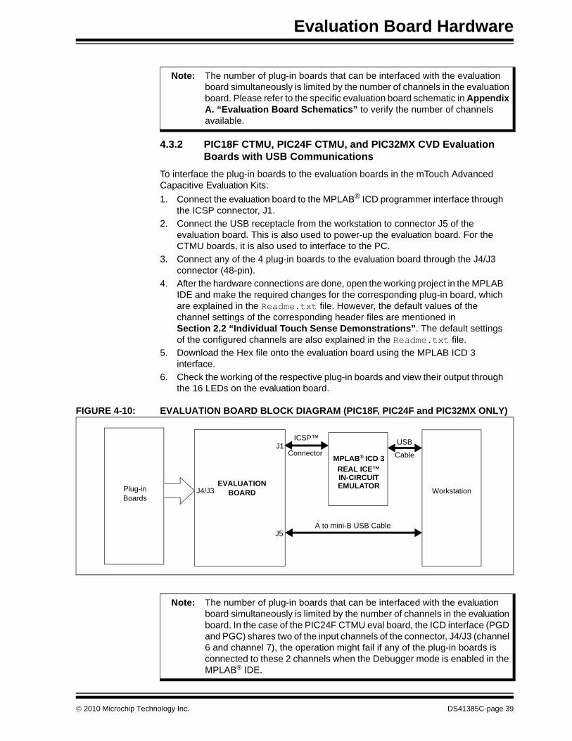
4.3.2 PIC18F CTMU, PIC24F CTMU, and PIC32MX CVD Evaluation Boards with USB Communications
To interface the plug-in boards to the evaluation boards in the mTouch Advanced Capacitive Evaluation Kits:1. Connect the evaluation board to the MPLAB® ICD programmer interface through
the ICSP connector, J1.2. Connect the USB receptacle from the workstation to connector J5 of the
evaluation board. This is also used to power-up the evaluation board. For the CTMU boards, it is also used to interface to the PC.
3. Connect any of the 4 plug-in boards to the evaluation board through the J4/J3 connector (48-pin).
4. After the hardware connections are done, open the working project in the MPLAB IDE and make the required changes for the corresponding plug-in board, which are explained in the Readme.txt file. However, the default values of the channel settings of the corresponding header files are mentioned in Section 2.2 “Individual Touch Sense Demonstrations”. The default settings of the configured channels are also explained in the Readme.txt file.
5. Download the Hex file onto the evaluation board using the MPLAB ICD 3 interface.
6. Check the working of the respective plug-in boards and view their output through the 16 LEDs on the evaluation board.
FIGURE 4-10: EVALUATION BOARD BLOCK DIAGRAM (PIC18F, PIC24F and PIC32MX ONLY)
Note: The number of plug-in boards that can be interfaced with the evaluation board simultaneously is limited by the number of channels in the evaluation board. Please refer to the specific evaluation board schematic in Appendix A. “Evaluation Board Schematics” to verify the number of channels available.
A to mini-B USB Cable
Workstation
USB
CableMPLAB® ICD 3REAL ICE™
ICSP™
ConnectorJ1
J5
EVALUATIONJ4/J3Plug-in
BoardsBOARD
IN-CIRCUITEMULATOR
Note: The number of plug-in boards that can be interfaced with the evaluation board simultaneously is limited by the number of channels in the evaluation board. In the case of the PIC24F CTMU eval board, the ICD interface (PGD and PGC) shares two of the input channels of the connector, J4/J3 (channel 6 and channel 7), the operation might fail if any of the plug-in boards is connected to these 2 channels when the Debugger mode is enabled in the MPLAB® IDE.
© 2010 Microchip Technology Inc. DS41385C-page 39
mTouch™ Advanced Capacitive Evaluation Kits User’s Guide
NOTES:
DS41385C-page 40 © 2010 Microchip Technology Inc.

mTouch™ ADVANCED CAPACITIVE
EVALUATION KITS USER’S GUIDEChapter 5. Troubleshooting
This chapter discusses common operational issues and methods to resolve them.
5.1 COMMON ISSUES1. The evaluation board does not respond to inputs (i.e., no lights when a key
plug-in or touch sensor is touched)Check the evaluation board for power:• Verify that USB power (VUSB, +5 VDC) is present on the USB connection.• If the evaluation board is connected to a computer through a USB hub, verify
the hub is powered and capable of providing power to downstream devices.• If the evaluation board is directly connected to a computer, verify that the USB
port used is active; try switching to another port.2. The touch sensors are abnormally sensitive or insensitive (generally
insensitive) to inputsCheck to make sure that the plug-in daughter boards are connected to the channels that are mentioned in the Readme.txt file.Check the bar graph settings for the sensors in the mTouch Sensing Solution software. The evaluation board’s trip point and other settings may have been changed to values that interfere with the default operation. To correct:• In the Settings dialog, verify that the Use Firmware Settings option is
selected.• If the Use Saved Value option is selected instead, change the trip point
values for each affected channel to a value that produces an appropriate response.
3. The evaluation board and the mTouch Sensing Solution Diagnostic Tool are installed and operating properly, but are not communicating with each otherThe USB host controller may not have enumerated the evaluation board correctly upon connection. To correct, try the following:• If the evaluation board is connected through an external USB hub, try
connecting it directly to a USB port on the host computer.• Disconnect the board, wait for 5 to 10 seconds, then reconnect the board.It is also possible that the USB host controller has dropped the communication channel. This happens occasionally when the evaluation board is placed into Standby mode and then powered up using the power control. In this case, dis-connect the evaluation board and reconnect after 5 to 10 seconds.
4. The board’s edge connector will add some additional parasitic capacitance to the system.
5. Touching the solder connections can create a very strong coupling to the sensor and trigger buttons.
© 2010 Microchip Technology Inc. DS41385C-page 41

mTouch™ Advanced Capacitive Evaluation Kits User’s Guide
NOTES:
DS41385C-page 42 © 2010 Microchip Technology Inc.
mTouch™ ADVANCED CAPACITIVEEVALUATION KITS USER’S GUIDE
Appendix A. Evaluation Board Schematics
This appendix provides the following schematics:• Figure A-1: “mTouch™ – PIC16F CSM/CVD Evaluation Board Schematic”• Figure A-2: “mTouch™ – PIC18F CTMU Evaluation Board Schematic”• Figure A-3: “mTouch™ – PIC24F CTMU Evaluation Board Schematic”• Figure A-4: “mTouch™ – PIC24H CVD Evaluation Board Schematic”• Figure A-5: “mTouch™ – PIC32MX CVD Evaluation Board Schematic”
© 2010 Microchip Technology Inc. DS41385C-page 43
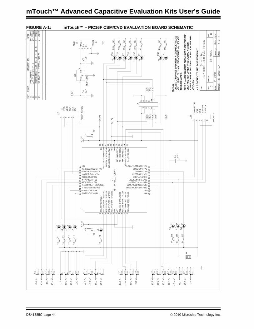
mTouch™ Advanced Capacitive Evaluation Kits User’s Guide
FIGURE A-1: mTouch™ – PIC16F CSM/CVD EVALUATION BOARD SCHEMATIC
DS41385C-page 44 © 2010 Microchip Technology Inc.
Evaluation Board Schematics
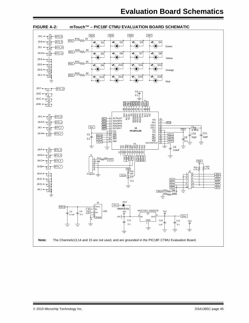
FIGURE A-2: mTouch™ – PIC18F CTMU EVALUATION BOARD SCHEMATIC
R25
J24.7K
VDDVDD
VDD
PGDPGC
RF5RF4
24681012
RC0RC1
RC6RC7
1357911
R244.7K
VBUS R23 56KR26 100K
J3:A 12
J3:D 78
J3:G 1314
J3:J 1920
J3:L BTN_82324
J3:K 2122
J3:I
RD4
1718
J3:H 1516
BTN_9
BTN_10
BTN_11
J4:F BTN_41112
J4:E 910
J4:C 56
J4:B 34
BTN_5
BTN_6
BTN_7
J4:L BTN_024
J4:K 2122
J4:I 1718
J4:H 1516
BTN_1
BTN_2
BTN_3
23
J4:A 2
J4:D 78
J4:G 1314
J4:J 1920
1
J3:F 2
J3:E 7
J3:C 13
J3:B 1920
BTN_12
8
14
R19RD0
VBUS
6
D-D+
12345
C44.7uF
C40.1
J5
VBUS
D-D+ USB
Shield +5V
VBUS
TP1
C13
0.1
MCP1702T–3302E/CB
3 IN OUTQ1
GND1
VDD
TP2
C18
1UF
C12
0.1
2
TP3
D11K
RD5
D2
RD6
D3
RD7
D4
R20RD1
D51K
D6 D7 D8
R21RD2
D91K
D10 D11 D12
R22RD3
D131K
D14 D15 D16
Green
Yellow
Orange
Red
RC7RX/DT1RD4/SPP42RD5/SPP53RD6/SPP64RD7SPP75VSS6VDD7RB08RB19RB210RB311
N/C 33RC0 32
OSC2 31OSC1 30
VSS 29VDD 28RE2 27RE1 26RE0 25RA5 24
VDDCORE/VCAP 23
PIC18F4XJ50
N/C
12
N/C
13
RB4
14
RB5
15
RB6
16RB
717
MCL
R18 19 20 21 22
44 43 42 41 40 39 38 37 36 35 34
RC6
RC5/
D+RC
4/D- NC
RD3/
SPP3
RD2/
SPP2
RD1/
SPP1
RD
0/SP
P0V U
SBRC
2RC
1N/
C
U1
RA1
RA3
RA2
RA0
VDD
C1
0.1
RC7RD4
RD6RD5
RD7
RC0
VDD
BTN_5BTN_4
C96.8uF
C80.1
C1022pf
C1122pf
8 MHzY1
BTN
_3
BTN
_2B
TN_1
BTN
_0
VDD
MCLR
PG
D
PG
C
RB
4
RB
5123456
J1
MCLR
Program
R17 100+5V
R1810K
C70.1
D17
Note: The Channels13,14 and 15 are not used, and are grounded in the PIC18F CTMU Evaluation Board.
BTN_7BTN_6
BTN_12
BTN_9
BTN_10
BTN_8
D-D+ RD
3R
D2
RD
0R
D1
VDD
C30.1
RC6
BTN
_11
RC
1
MBR0520L
© 2010 Microchip Technology Inc. DS41385C-page 45
mTouch™ Advanced Capacitive Evaluation Kits User’s Guide
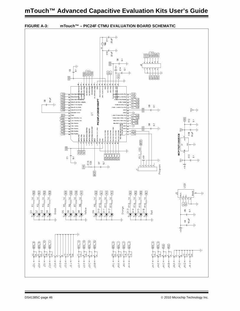
FIGURE A-3: mTouch™ – PIC24F CTMU EVALUATION BOARD SCHEMATIC
22 p
F22
pF
10
F
PIC24FJ128GB106I/PT
MCP1702T-3302E/CB
10
F
10
F
DS41385C-page 46 © 2010 Microchip Technology Inc.
Evaluation Board Schematics
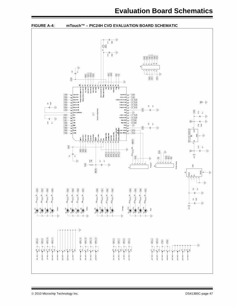
FIGURE A-4: mTouch™ – PIC24H CVD EVALUATION BOARD SCHEMATIC
RE4
RE2
RE1
RF1
RF0
RD7
RD5
RD4
RD2
RD1
PGC
BTN_9
BTN_10
BTN_13
BTN_14
RF4
RF5
Red
Yel
low
RE
6
RE
5
RE
3
RE
1
RE
0
RD
7
RD
6
RD
4
RD
3
RD
2
RD
0
RX
SD
A
TX
VD
D
MC
LR
VD
D
RF
1
+5V
Ora
nge
Gre
en
RE
7
RE
4
RE
2
RD
5
RD
1
MC
LR
SC
L
R18
10K
VD
D
VD
D
RE0
RE3
0.1
C12
VD
D
RD6
VDD
TP
3
RD3
RF
4
RF
0
C10
20pf
C11
20pf
C4
10uF
0.1
C5
3D
+4 51
VB
US
2D
-
6
Shi
eld
J5
+5V
0.1
C7
VD
D
0.1
C6
PGD
BTN_8
BTN_12
BTN_11
BTN_15
VD
D
910
34
1112
12
5 7
6 8
J2
PG
D
PG
C
BT
N_4
BT
N_3
BT
N_2
BT
N_0
BT
N_1
4
BT
N_1
3
BT
N_1
1
BT
N_1
0
BT
N_8
US
B
Pro
gram
R15
1K
R10
1K
R8
1K
R5
1K
R4
1K
R1
1K
R17
100
BT
N_1
BT
N_2
BT
N_4
BT
N_5
RE
7
RE
6
RD
9
RD
10
VD
D
VD
D
RX
SC
L
RD
9
RD
10
RD
0
13 14J4
:G
19 20J4
:J
3 4J4
:B
1 2J4
:A
11 12J4
:F
9 10J4
:EB
TN
_5
17 18J4
:I
15 16J4
:H
BT
N_1
23 24J4
:L
3 4J3
:B
5 6J3
:C
BT
N_1
5
11 12J3
:FB
TN
_12
13 14J3
:G
7 8J3
:D
15 16J3
:H
17 18J3
:I
BT
N_9
23 24J3
:L
PIC
kit S
eria
l
R14
1K
R16
1KD
16
D15
D14
R13
1KD
13
R12
1KD
12
R11
1KD
11
R9
1KD
9
R7
1KD
7
D8
R6
1K
D5
R3
1KD
3
D4
R2
1K
D1
0.1
C13
C18
10uF
TP
1T
P2
VD
D
BT
N_0
BT
N_3
RE
5
0.1
C15
C9
10uF
RF
5
RD
11
TX
SD
A
8MH
z
Y1
RD
11
0.1
C2
7 8J4
:D
5 6J4
:C
21 22J4
:K
9 10J3
:E
19 20J3
:J
1 2J3
:A
21 22J3
:K
D10
41 632 5
J1
D2
D6
1GN
D
3IN
2O
UT
MC
P17
02T
-330
2E/C
B
0.1
C3
0.1
C1
41 632 5
J6
PIC
24H
128G
P50
6
© 2010 Microchip Technology Inc. DS41385C-page 47
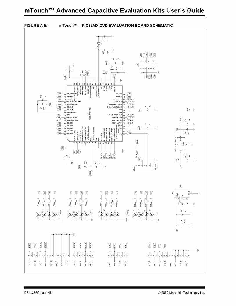
mTouch™ Advanced Capacitive Evaluation Kits User’s Guide
FIGURE A-5: mTouch™ – PIC32MX CVD EVALUATION BOARD SCHEMATIC
RE4
RE2
RE1
RF1
RF0
RD7
RD5
RD4
RD2
RD1
PGC
BTN_9
BTN_10
BTN_13
BTN_14
RF4
RF5
D-
Red
Yel
low
US
B
RE
6
RE
5
RE
3
RE
1
RE
0
RD
7
RD
6
RD
4
RD
3
RD
2
RD
0
VD
D
MC
LR
RF
3
RF
1
C4
10uF
0.1
C5
D+
Ora
nge
Gre
en
RE
7
RE
4
RE
2
RD
5
RD
1
MC
LR
0.1
C13
+5V
R18
10K
VD
D
C18
10uF
VD
D
RE0
RE3
TP
3
VD
D
VDD
RD6
RD3
0.1
C15
RF
4
RF
0
RF
3
VD
D
C10
20pf
C11
20pf
+5V
TP
1
0.1
C7
VD
D
TP
2
0.1
C6
PGD
BTN_8
BTN_12
BTN_11
BTN_15
VD
D
+5V
0.1
C8
910
34
1112
12
5 7
6 8
J2
PG
D
PG
C
BT
N_4
BT
N_3
BT
N_2
BT
N_0
BT
N_1
4
BT
N_1
3
BT
N_1
1
BT
N_1
0
BT
N_8
Pro
gram
R15
1K
R10
1K
R8
1K
R5
1K
R4
1K
R1
1K
VD
D
R17
100
BT
N_1
BT
N_2
BT
N_4
BT
N_5
RE
7
RE
6
RD
9
RD
10
VD
D
VD
D
D+
RD
9
RD
10
RD
0
13 14J4
:G
19 20J4
:J
3 4J4
:B
1 2J4
:A
11 12J4
:F
9 10J4
:EB
TN
_5
17 18J4
:I
15 16J4
:H
BT
N_1
23 24J4
:L
3 4J3
:B
5 6J3
:C
BT
N_1
5
11 12J3
:FB
TN
_12
13 14J3
:G
7 8J3
:D
15 16J3
:H
17 18J3
:I
BT
N_9
23 24J3
:L
R14
1K
R16
1KD
16
D15
D14
R13
1KD
13
R12
1KD
12
R11
1KD
11
R9
1KD
9
R7
1KD
7
D8
R6
1K
D5
R3
1KD
3
D4
R2
1K
D1
0.1
C12
BT
N_0
BT
N_3
RE
5
C9
10uF
RF
5
RD
11
0.1
C14
D-
8MH
z
Y1
RD
11
0.1
C2
7 8J4
:D
5 6J4
:C
21 22J4
:K
9 10J3
:E
19 20J3
:J
1 2J3
:A
21 22J3
:K
3D
+4 51
VB
US
2D
-
6
Shi
eld
J5
D10
D2
D6
1GN
D
3IN
2O
UT
MC
P17
02T
-330
2E/C
B
0.1
C3
0.1
C1
41 632 5
J1
U1
PIC
32M
X79
5F51
2H
DS41385C-page 48 © 2010 Microchip Technology Inc.
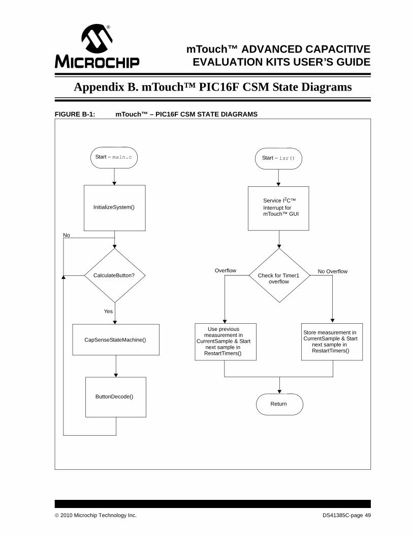
mTouch™ ADVANCED CAPACITIVEEVALUATION KITS USER’S GUIDE
Appendix B. mTouch™ PIC16F CSM State Diagrams
FIGURE B-1: mTouch™ – PIC16F CSM STATE DIAGRAMS
Start – main.c
InitializeSystem()
CalculateButton?
CapSenseStateMachine()
No
Yes
ButtonDecode()
Start – isr()
Service I2C™Interrupt formTouch™ GUI
Check for Timer1overflow
Overflow No Overflow
Use previousmeasurement in
CurrentSample & Startnext sample inRestartTimers()
Store measurement inCurrentSample & Start
next sample inRestartTimers()
Return
© 2010 Microchip Technology Inc. DS41385C-page 49

mTouch™ Advanced Capacitive Evaluation Kits User’s Guide
FIGURE B-1: mTouch™ – PIC16F CSM STATE DIAGRAMS (CONTINUED)
InitializeSystem()
No
Yes
Return
No
Yes
Is ReleaseAverage[ButtonIndex]outside of
ReleaseAverageGuardBand?
InitializeSystem()
Is SupplyVoltage outside ofVoltageGuardBand?
Start –CapSenseStateMachine()
Correct, Scaleand Cap
CurrentSample
CalculatePercentReleased
State Machine Design(next page)
DS41385C-page 50 © 2010 Microchip Technology Inc.
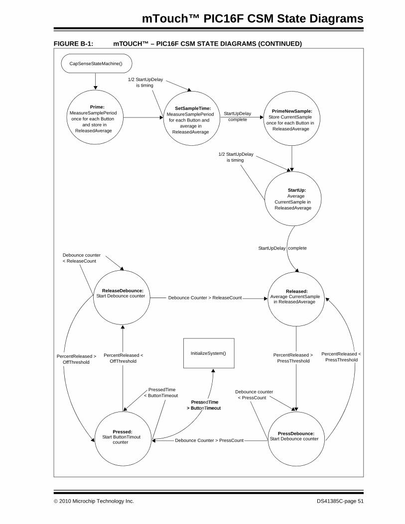
mTouch™ PIC16F CSM State Diagrams
FIGURE B-1: mTOUCH™ – PIC16F CSM STATE DIAGRAMS (CONTINUED)
Prime:MeasureSamplePeriodonce for each Button
and store inReleasedAverage
SetSampleTime:MeasureSamplePeriodfor each Button and
average in ReleasedAverage
PrimeNewSample:Store CurrentSample
once for each Button inReleasedAverage
CapSenseStateMachine()
1/2 StartUpDelayis timing
StartUpDelaycomplete
StartUp:Average
CurrentSample inReleasedAverage
1/2 StartUpDelayis timing
StartUpDelay completeDebounce counter< ReleaseCount
Debounce Counter > ReleaseCount
InitializeSystem()
Debounce Counter > PressCount
PressedTime< ButtonTimeout
Debounce counter< PressCount
PressedTime> ButtonTimeout
ReleaseDebounce:Start Debounce counter
Released:Average CurrentSample
in ReleasedAverage
PressDebounce:Start Debounce counter
Pressed:Start ButtonTimout
counter
PercentReleased <OffThreshold
PressedTime> ButtonTimeout
PercentReleased >OffThreshold
PercentReleased >PressThreshold
PercentReleased <PressThreshold
© 2010 Microchip Technology Inc. DS41385C-page 51
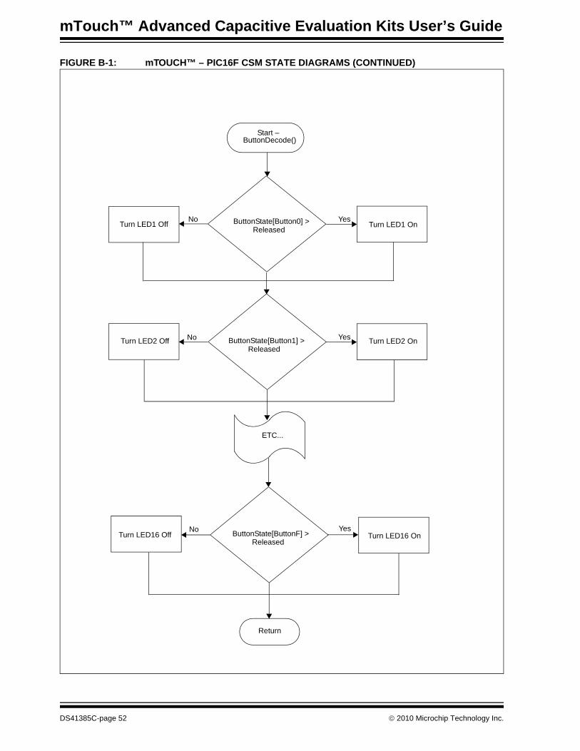
mTouch™ Advanced Capacitive Evaluation Kits User’s Guide
FIGURE B-1: mTOUCH™ – PIC16F CSM STATE DIAGRAMS (CONTINUED)
Start –ButtonDecode()
ButtonState[Button0] >Released
ButtonState[Button1] >Released
ETC...
ButtonState[ButtonF] >Released
Return
Turn LED1 Off Turn LED1 On
Turn LED2 On
Turn LED16 On
Turn LED2 Off
Turn LED16 Off
Yes
Yes
Yes
No
No
No
DS41385C-page 52 © 2010 Microchip Technology Inc.

mTouch™ ADVANCED CAPACITIVE
EVALUATION KITS USER’S GUIDEIndexNumerics K
2-Channel Slider Plug-in .......................................... 19BBlock Diagrams
CSM Evaluation Layout (Top)........................... 32PIC16F CSM Evaluation Board
Application Side.............................27, 30PIC18F CTMU Evaluation Board
Application Side.................................. 28PIC24F CTMU Evaluation Board
Application Side.............................29, 31Board Components .......................................32, 34, 36Board H/W ............................................................... 27Board Setup ............................................................. 16
Connecting the H/W.......................................... 16Installing the S/W.............................................. 16Interfacing the Plug-in Boards .......................... 39
CCharge Time Measurement Unit (CTMU) ...........17, 29Components
External Plug-in Components ........................... 35ICSP Programming Header .............................. 35PIC18F46J50 Microcontroller ........................... 35PIC24FJ128GB106 Microcontroller .................. 34PIC32MX795F512H Microcontroller ................. 35Plug-in Interface Connector .............................. 35Plug-in Sensor LEDs ........................................ 35Power Supply.................................................... 35USB mini-B Receptacle .................................... 35
Configuration SettingsReadme ............................................................ 19
CSM State Diagrams ............................................... 49Customer Notification Service.................................. 10Customer Support .................................................... 11
DDemonstration Application ....................................... 17Direct Key Plug-in .................................................... 18Documentation
Conventions........................................................ 6Layout ................................................................. 5
EEvaluation Board
CTMU and CVD Component Layout (Top Side)34
HHost Computer Requirements.................................. 15
IInitial Board Setup.................................................... 16Internet Address....................................................... 10
Kit Contents.............................................................. 14
MMatrix Key Plug-in .................................................... 19Microchip Internet Web Site ..................................... 10mTouch Sensing Solution
Diagnostic Tool ................................................. 21Introduction ....................................................... 21
OOperational Requirements ....................................... 15
PPIC16F1937 Microcontroller .............................. 27, 30
PIC16F CSM Evaluation Board ........................ 17PIC18F46J50 Microcontroller................................... 28PIC24FJ128GB106 Microcontroller ......................... 29PIC32MX795F512H Microcontroller ........................ 34Plug in Power ........................................................... 20Plug in the Sensors .................................................. 20
RReadme
Configuration Settings....................................... 19Recommended Reading ............................................ 7
SSchematics
PIC16F CSM Evaluation Board ........................ 44PIC18F CTMU Evaluation Board ...................... 45PIC24F CTMU Evaluation Board ...................... 46PIC24H CVD Evaluation Board ........................ 47PIC32MX CVD Evaluation Board...................... 48
TTouch Interface ........................................................ 17
Sensor Persistence........................................... 18Touch Sensitivity............................................... 17
Touch Sense Demonstrations.................................. 1812-Key Matrix Plug-in Board ............................. 192-Channel Slider Plug-in Board ........................ 194-Channel Slider Plug-in ................................... 198-Key Direct Plug-in Board ............................... 18
Troubleshooting ....................................................... 41
UUsing the mTouch™ Sensing Solution
Diagnostic Tool ................................................. 21
WWarranty Registration ................................................ 7WWW Address......................................................... 10
© 2010 Microchip Technology Inc. DS41385C-page 53
DS41385C-page 54 © 2010 Microchip Technology Inc.
AMERICASCorporate Office2355 West Chandler Blvd.Chandler, AZ 85224-6199Tel: 480-792-7200 Fax: 480-792-7277Technical Support: http://support.microchip.comWeb Address: www.microchip.comAtlantaDuluth, GA Tel: 678-957-9614 Fax: 678-957-1455BostonWestborough, MA Tel: 774-760-0087 Fax: 774-760-0088ChicagoItasca, IL Tel: 630-285-0071 Fax: 630-285-0075ClevelandIndependence, OH Tel: 216-447-0464 Fax: 216-447-0643DallasAddison, TX Tel: 972-818-7423 Fax: 972-818-2924DetroitFarmington Hills, MI Tel: 248-538-2250Fax: 248-538-2260KokomoKokomo, IN Tel: 765-864-8360Fax: 765-864-8387Los AngelesMission Viejo, CA Tel: 949-462-9523 Fax: 949-462-9608Santa ClaraSanta Clara, CA Tel: 408-961-6444Fax: 408-961-6445TorontoMississauga, Ontario, CanadaTel: 905-673-0699 Fax: 905-673-6509
ASIA/PACIFICAsia Pacific OfficeSuites 3707-14, 37th FloorTower 6, The GatewayHarbour City, KowloonHong KongTel: 852-2401-1200Fax: 852-2401-3431Australia - SydneyTel: 61-2-9868-6733Fax: 61-2-9868-6755China - BeijingTel: 86-10-8528-2100 Fax: 86-10-8528-2104China - ChengduTel: 86-28-8665-5511Fax: 86-28-8665-7889China - ChongqingTel: 86-23-8980-9588Fax: 86-23-8980-9500China - Hong Kong SARTel: 852-2401-1200 Fax: 852-2401-3431China - NanjingTel: 86-25-8473-2460Fax: 86-25-8473-2470China - QingdaoTel: 86-532-8502-7355Fax: 86-532-8502-7205China - ShanghaiTel: 86-21-5407-5533 Fax: 86-21-5407-5066China - ShenyangTel: 86-24-2334-2829Fax: 86-24-2334-2393China - ShenzhenTel: 86-755-8203-2660 Fax: 86-755-8203-1760China - WuhanTel: 86-27-5980-5300Fax: 86-27-5980-5118China - XianTel: 86-29-8833-7252Fax: 86-29-8833-7256China - XiamenTel: 86-592-2388138 Fax: 86-592-2388130China - ZhuhaiTel: 86-756-3210040 Fax: 86-756-3210049
ASIA/PACIFICIndia - BangaloreTel: 91-80-3090-4444 Fax: 91-80-3090-4123India - New DelhiTel: 91-11-4160-8631Fax: 91-11-4160-8632India - PuneTel: 91-20-2566-1512Fax: 91-20-2566-1513Japan - YokohamaTel: 81-45-471- 6166 Fax: 81-45-471-6122Korea - DaeguTel: 82-53-744-4301Fax: 82-53-744-4302Korea - SeoulTel: 82-2-554-7200Fax: 82-2-558-5932 or 82-2-558-5934Malaysia - Kuala LumpurTel: 60-3-6201-9857Fax: 60-3-6201-9859Malaysia - PenangTel: 60-4-227-8870Fax: 60-4-227-4068Philippines - ManilaTel: 63-2-634-9065Fax: 63-2-634-9069SingaporeTel: 65-6334-8870Fax: 65-6334-8850Taiwan - Hsin ChuTel: 886-3-6578-300Fax: 886-3-6578-370Taiwan - KaohsiungTel: 886-7-536-4818Fax: 886-7-536-4803Taiwan - TaipeiTel: 886-2-2500-6610 Fax: 886-2-2508-0102Thailand - BangkokTel: 66-2-694-1351Fax: 66-2-694-1350
EUROPEAustria - WelsTel: 43-7242-2244-39Fax: 43-7242-2244-393Denmark - CopenhagenTel: 45-4450-2828 Fax: 45-4485-2829France - ParisTel: 33-1-69-53-63-20 Fax: 33-1-69-30-90-79Germany - MunichTel: 49-89-627-144-0 Fax: 49-89-627-144-44Italy - Milan Tel: 39-0331-742611 Fax: 39-0331-466781Netherlands - DrunenTel: 31-416-690399 Fax: 31-416-690340Spain - MadridTel: 34-91-708-08-90Fax: 34-91-708-08-91UK - WokinghamTel: 44-118-921-5869Fax: 44-118-921-5820
Worldwide Sales and Service
01/05/10