Embed Size (px)
Citation preview
Technical Description
FBP FieldBusPlug MTQ22-FBP Modbus TCP Interface
Description
The MTQ22-FBP Ethernet adapter module allows the connection of UMC or FBP devices to Ethernet.
MTQ22-FBP Modbus TCP Interface
Technical Description
MTQ22-FBP Modbus TCP Interface
Technical Description
- 2 -MTQ22-FBP FieldBusPlug / Issue: 07.2015
Please note the followingTarget group
This description is intended for the use of trained specialists in electrical installation and control and automation engi-neering, who are familiar with the applicable national standards.
Safety requirements
The responsible staff must ensure that the application or use of the products described satisfy all the requirements for safety, including all the relevant laws, regulations, guidelines and standards.
Using this Handbook
Symbols
This technical document contains sentinels to point the reader to important information, potential risks and precaution information. The following symbols are used:
Sign to indicate a potential dangerous situation that can cause damage of the connected devices or the environment.
Sign to indicate important information and conditions.
Sign that indicates a potential dangerous situation that can cause human injuries.
Terms and Abbreviations
MRP Media redundancy protocol
MRC Media redundancy client
MRM Media redundancy manager
TCP/IP Transmission Control Protocol / Internet Protocol
UDP User Datagram Protocol
Client / Server The Modbus TCP messaging service provides a Client/Server communication between devices connected on an Ethernet TCP/IP network. The device initiating the communication (e.g. a PLC) is called the client. The device answering the request is called the server (the MTQ22-FBP in this case).
Master / Slave Master/slave is a model of communication where one device e.g. a PLC has control over one or more other devices (here MTQ22-FBP and UMC). In the Modbus TCP context the master is the client and the slave is the server.
MAC Medium Access Control
MAC Address Unique address of every Ethernet device. The MAC address of the MTQ22-FBP is printed on the nameplate.
PLC Programmable Logic Controller
Related Documents
Technical Documentation Document No.
MTQ22-FBP Modbus TCP Interface
Technical Description
MTQ22-FBP Modbus TCP Interface
Technical Description
- 3 - MTQ22-FBPFieldBusPlug / Issue: 07.2015
Content
Overview ...................................................................................................................................................5
Ethernet ..............................................................................................................................................6
Modbus TCP .......................................................................................................................................6
MTQ22-FBP ........................................................................................................................................7
Supported FBP devices ......................................................................................................................7
Installation ................................................................................................................................................8
Mounting and Dismounting ................................................................................................................8
Electrical Installation ...........................................................................................................................8
Ethernet Commuication ...........................................................................................................................8
Configuration ..........................................................................................................................................16
Online Mode .....................................................................................................................................16
Modbus TCP Register Map ....................................................................................................................19
Supported Function Codes ..............................................................................................................19
Modbus Address Table .....................................................................................................................19
MTQ22 Status Data ..........................................................................................................................19
Reading and Writing FBP Device Data .............................................................................................20
Example Addressmap with UMC100 ................................................................................................22
Data Access in one block ordered by device ...................................................................................26
Data access in one block ordered by data type ...............................................................................28
Diagnosis / Behaviour in Case of an Error .............................................................................................30
LED status indications ......................................................................................................................30
Reading the FBP device communication status...............................................................................31
Technical Data ........................................................................................................................................32
General .............................................................................................................................................32
EMC ..................................................................................................................................................32
Ethernet and Modbus TCP Performance Data .................................................................................33
Ordering Data ...................................................................................................................................33
Dimensions .......................................................................................................................................34
MTQ22-FBP Modbus TCP Interface
Technical Description
MTQ22-FBP Modbus TCP Interface
Technical Description
- 4 -MTQ22-FBP FieldBusPlug / Issue: 07.2015
Document History
D0202 page 29, 33 Supplementation of table values and supported bitrate
D0202 Rev B various Update of images, LLDP information added
MTQ22-FBP Modbus TCP Interface
Technical Description
MTQ22-FBP Modbus TCP Interface
Technical Description
- 5 - MTQ22-FBPFieldBusPlug / Issue: 07.2015
OverviewThe MTQ22-FBP Ethernet adapter module supports the Modbus TCP network protocol. This chapter contains a short description of Modbus TCP and the MTQ22-FBP Ethernet adapter module.
Highlighted Features
The MTQ22-FBP Ethernet adapter module provides Ethernet connectivity for FieldbusPlug (FBP) devices such as UMC100 or PST.
Up to four FBP devices can be connected to one MTQ22-FBP. This allows a very cost efficient connection of FBP devices to Ethernet.
Through the MTQ22-FBP Ethernet Adapter module it is possible to:
- give control commands to the device (Start, Stop, Auto, etc.). The meaning of the commands depends on the connected device
- read status information and actual values from the device
- change parameter values
- read maintenance counters
- reset a trip
A built in two-port switch allows the flexible usage in bus, star or ring network topologies.
Up to four masters can concurrently access the connected devices. The master connections can be supervised.
Access via Modbus TCP can be restricted to a limited set of IP addresses.
The Media Redundancy Protocol (MRP) is implemented (client). MRP is standardized in IEC/EN 62439-2 and offers cable redundancy in case of a single failure.
The Modbus address map offers flexible data access to best suit the needs of MobbusTCP client (e.g. PLC).
Location supervision for detecting of interchanged drawers in withdrawable systems.

MTQ22-FBP Modbus TCP Interface
Technical Description
MTQ22-FBP Modbus TCP Interface
Technical Description
- 6 -MTQ22-FBP FieldBusPlug / Issue: 07.2015
Ethernet
Ethernet standards support a variety of physical media (coaxial cable, twisted pair, fiber optics) and topologies (bus, ring and star). The MTQ22-FBP Ethernet Adapter supports twisted pair as the physical media in a bus, ring and star topology. Possible topologies are shown in Figure 1. The MTQ22-FBP is compatible with Ethernet standards IEEE 802.3 and IEEE 802.3u.
MTQ22
FBPDevice
FBPDevice
FBPDevice
FBPDevice
MTQ22
FBPDevice
FBPDevice
FBPDevice
FBPDevice
Switch
MTQ22
FBPDevice
FBPDevice
FBPDevice
FBPDevice
MTQ22
FBPDevice
FBPDevice
FBPDevice
FBPDevice
MTQ22
FBPDevice
FBPDevice
FBPDevice
FBPDevice
MTQ22
FBPDevice
FBPDevice
FBPDevice
FBPDevice
Twisted Pair Ethenet
Star Bus Ring
Switch Switch
FBP Interface
Figure 1: Different topologies that can be realized with the MTQ22-FBP Ethernet Adapeter. For the ring structure a special switch must be used. See chapter Communication for more information.
Modbus TCP
Modbus TCP is a variant of the Modbus family of simple, vendor neutral communication protocols intended for supervision and control of automation equipment. Specifically, it covers the use of Modbus messaging over TCP connection on an IP network.
The implementation of the Modbus TCP server in the MTQ22-FBP module is done according to
- Modbus Application Protocol Specification v1.1b
- Modbus Messaging on TCP/IP Implementation Guide v1.0b
The supported Modbus commands are listed in chapter Communication. Four simultaneous Modbus TCP connections are supported.
Further information on the Modbus TCP protocol is available on the world wide web from www.modbus.org.
MTQ22-FBP Modbus TCP Interface
Technical Description
MTQ22-FBP Modbus TCP Interface
Technical Description
- 7 - MTQ22-FBPFieldBusPlug / Issue: 07.2015
MTQ22-FBP
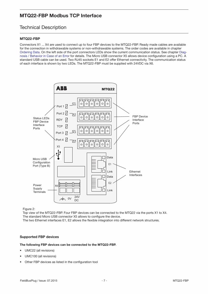
Connectors X1 ... X4 are used to connect up to four FBP devices to the MTQ22-FBP. Ready made cables are available for the connection in withdrawable systems or non-withdrawable systems. The order codes are available in chapter Ordering Data. On the left side of the port connectors LEDs show the current communication status. See chapter Diag-nosis / Behavior in Case of an Error for details. The Micro USB connector X5 allows device configuration using a PC. A standard USB cable can be used. Two RJ45 sockets E1 and E2 offer Ethernet connectivity. The communication status of each interface is shown by two LEDs. The MTQ22-FBP must be supplied with 24VDC via X6.
Figure 2: Top view of the MTQ22-FBP. Four FBP devices can be connected to the MTQ22 via the ports X1 to X4. The standard Micro USB connector X5 allows to configure the device. The two Ethernet interfaces E1, E2 allows the flexible integration into different network structures.
Supported FBP devices
The following FBP devices can be connected to the MTQ22-FBP.
• UMC22 (all revisions)
• UMC100 (all revisions)
• Other FBP devices as listed in the configuration tool
24VDC0V
Port 1
Port 2
Port 3
RDY
TCP
Link
Data
Link
Data
MTQ22
Port 4
X1
X2
X3
X4
X5
X6
E1
E2
FBP DeviceInterfacePorts
Status LEDsFBP DeviceInterfacePorts
PowerSupplyTerminals
Micro USBConfigurationPort (Type B)
EthernetInterfaces
MTQ22-FBP Modbus TCP Interface
Technical Description
MTQ22-FBP Modbus TCP Interface
Technical Description
- 8 -MTQ22-FBP FieldBusPlug / Issue: 07.2015
Installation
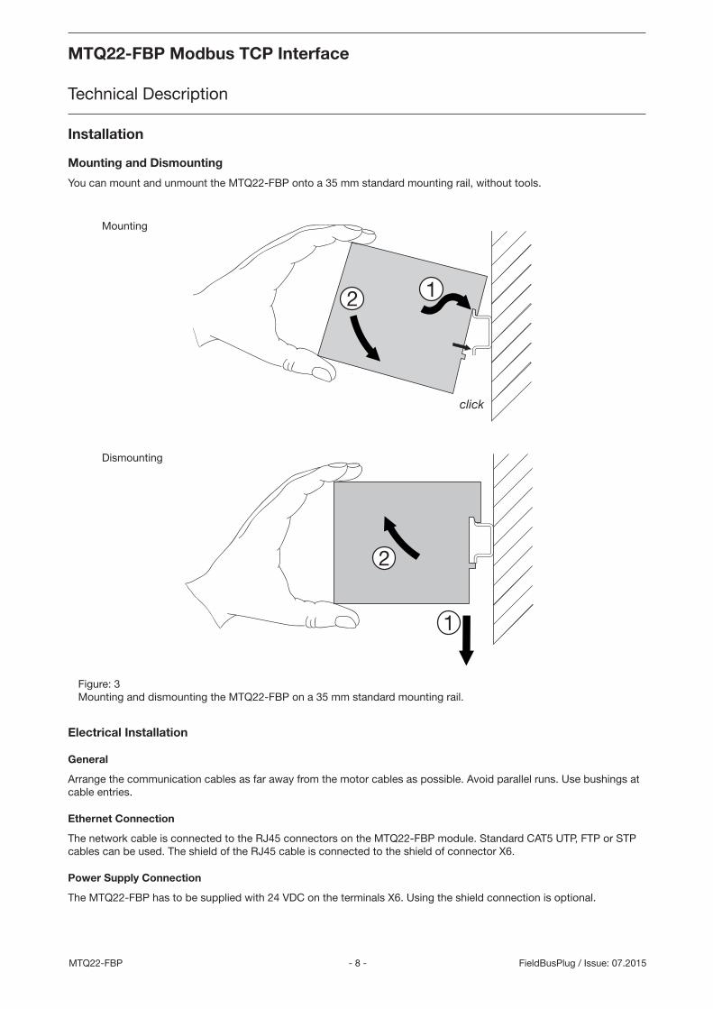
Mounting and Dismounting
You can mount and unmount the MTQ22-FBP onto a 35 mm standard mounting rail, without tools.
Electrical Installation
General
Arrange the communication cables as far away from the motor cables as possible. Avoid parallel runs. Use bushings at cable entries.
Ethernet Connection
The network cable is connected to the RJ45 connectors on the MTQ22-FBP module. Standard CAT5 UTP, FTP or STP cables can be used. The shield of the RJ45 cable is connected to the shield of connector X6.
Power Supply Connection
The MTQ22-FBP has to be supplied with 24 VDC on the terminals X6. Using the shield connection is optional.
Mounting
Dismounting
Figure: 3 Mounting and dismounting the MTQ22-FBP on a 35 mm standard mounting rail.
MTQ22-FBP Modbus TCP Interface
Technical Description
MTQ22-FBP Modbus TCP Interface
Technical Description
- 9 - MTQ22-FBPFieldBusPlug / Issue: 07.2015
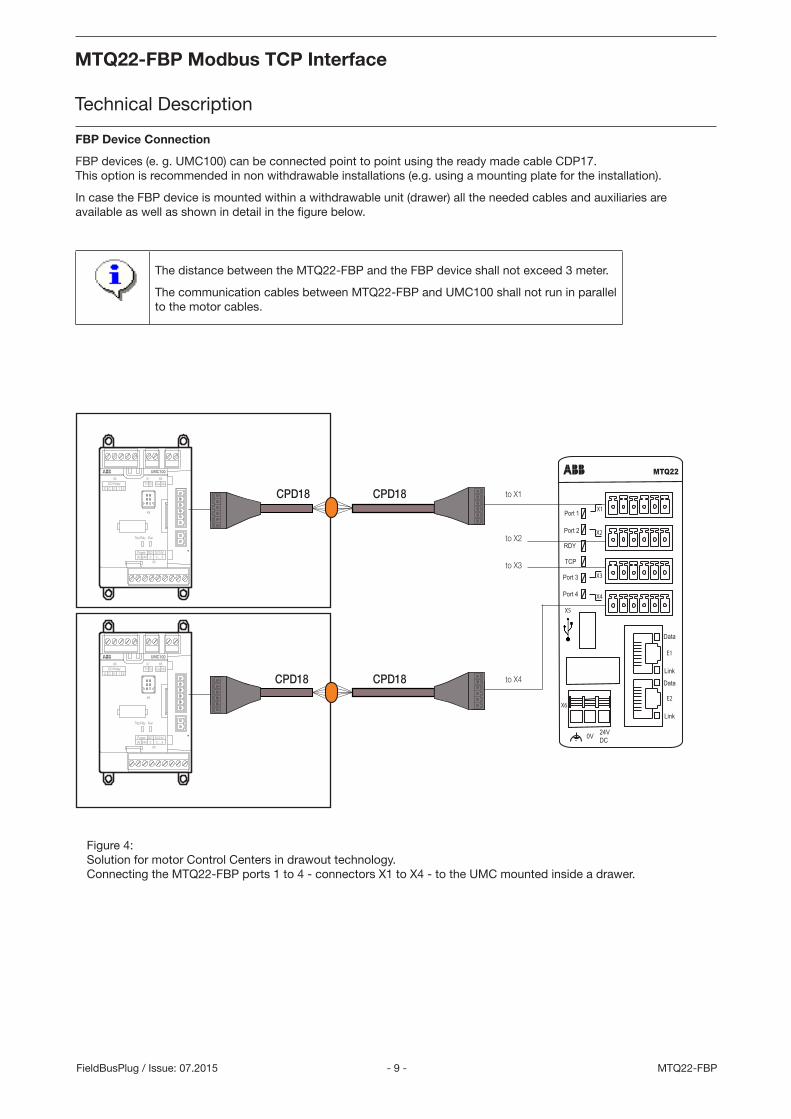
FBP Device Connection
FBP devices (e. g. UMC100) can be connected point to point using the ready made cable CDP17. This option is recommended in non withdrawable installations (e.g. using a mounting plate for the installation).
In case the FBP device is mounted within a withdrawable unit (drawer) all the needed cables and auxiliaries are available as well as shown in detail in the figure below.
The distance between the MTQ22-FBP and the FBP device shall not exceed 3 meter.
The communication cables between MTQ22-FBP and UMC100 shall not run in parallel to the motor cables.
Figure 4: Solution for motor Control Centers in drawout technology. Connecting the MTQ22-FBP ports 1 to 4 - connectors X1 to X4 - to the UMC mounted inside a drawer.
24VDC0V
Port 1
Port 2
Port 3
RDY
TCP
Link
Data
Link
Data
MTQ22
Port 4
X1
X2
X3
X4
X5
X6
E1
E2
X6 X7 X8
X9
X5
T1 T2 Ca CbDO RelayCC 0 1 2
Run
DI 24VDOPower0V 24V 0 ... 53
Trip/Rdy
X6 X7 X8
X9
X5
T1 T2 Ca CbDO RelayCC 0 1 2
Run
DI 24VDOPower0V 24V 0 ... 53
Trip/Rdy
CPD18CPD18 to X1
CPD18CPD18 to X4
to X3
to X2
MTQ22-FBP Modbus TCP Interface
Technical Description
MTQ22-FBP Modbus TCP Interface
Technical Description
- 10 -MTQ22-FBP FieldBusPlug / Issue: 07.2015
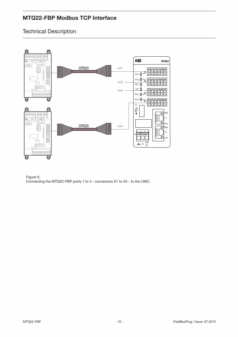
Figure 5: Connecting the MTQ22-FBP ports 1 to 4 - connectors X1 to X4 - to the UMC.
24VDC0V
Port 1
Port 2
Port 3
RDY
TCP
Link
Data
Link
Data
MTQ22
Port 4
X1
X2
X3
X4
X5
X6
E1
E2
X6 X7 X8
X9
X5
T1 T2 Ca CbDO RelayCC 0 1 2
Run
DI 24VDOPower0V 24V 0 ... 53
Trip/Rdy
X6 X7 X8
X9
X5
T1 T2 Ca CbDO RelayCC 0 1 2
Run
DI 24VDOPower0V 24V 0 ... 53
Trip/Rdy
CPD23
CPD23
to X1
to X4
to X3
to X2
MTQ22-FBP Modbus TCP Interface
Technical Description
MTQ22-FBP Modbus TCP Interface
Technical Description
- 11 - MTQ22-FBPFieldBusPlug / Issue: 07.2015
Ethernet Commuication
Star topology
In star topology only one RJ45 cable must be connected between the MTQ22-FBP and a switch. An unmanaged stan-dard switch can be used in this operation mode.
Bus topology
In bus topology the internal two-port-switch of the MTQ22-FBP is used to connect MTQ22-FBP to MTQ22-FBP. Only the first MTQ22-FBP in the chain needs to be connected to a switch. The second Ethernet port of the last MTQ22-FBP can be left unconnected. An unmanaged standard switch can be used in this operation mode.
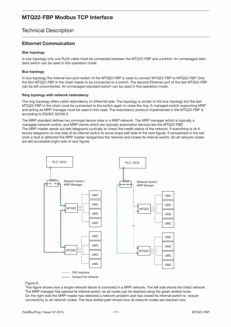
Ring topology with network redundancy
The ring topology offers cable redundancy on Ethernet side. The topology is similar to the bus topology but the last MTQ22-FBP in the chain must be connected to the switch again to close the ring. A managed switch supporting MRP and acting as MRP manager must be used in this case. The redundancy protocol implemented in the MTQ22-FBP is according to EN/IEC 62439-2.
The MRP standard defines two principal device roles in a MRP network. The MRP manager which is typically a managed network switch, and MRP clients which are typically automation devices like the MTQ22-FBP. The MRP master sends out test telegrams cyclically to check the health status of the network. If everything is ok it blocks telegrams on one side of its internal switch to avoid loops (left side of the next figure). If somewhere in the net-work a fault is detected the MRP master reorganizes the network and closes its internal switch. So all network nodes are still accessible (right side of next figure).
Network Switch /MRP Manager
MTQ22
UMC
UMC
UMC
UMC
UMC
UMC
UMC
UMC
UMC
UMC
UMC
UMC
UMC
UMC
UMC
UMC
MTQ22
Twisted Pair Ethenet
PLC / DCS
Network Switch /MRP Manger
MTQ22
MTQ22
PLC / DCS
FBP Interface
Figure 6: This figure shows how a single network failure is corrected in a MRP network. The left side shows the intact network. The MRP manager has opened its internal switch, so all nodes can be reached using the green dotted route. On the right side the MRP master has detected a network problem and has closed its internal switch to ensure connectivity to all network nodes. The blue dotted path shows how all network nodes are reached now.
MTQ22-FBP Modbus TCP Interface
Technical Description
MTQ22-FBP Modbus TCP Interface
Technical Description
- 12 -MTQ22-FBP FieldBusPlug / Issue: 07.2015
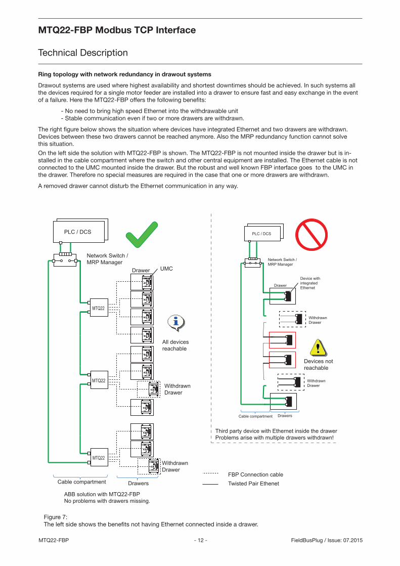
Ring topology with network redundancy in drawout systems
Drawout systems are used where highest availability and shortest downtimes should be achieved. In such systems all the devices required for a single motor feeder are installed into a drawer to ensure fast and easy exchange in the event of a failure. Here the MTQ22-FBP offers the following benefits:
- No need to bring high speed Ethernet into the withdrawable unit - Stable communication even if two or more drawers are withdrawn.
The right figure below shows the situation where devices have integrated Ethernet and two drawers are withdrawn. Devices between these two drawers cannot be reached anymore. Also the MRP redundancy function cannot solve this situation.
On the left side the solution with MTQ22-FBP is shown. The MTQ22-FBP is not mounted inside the drawer but is in-stalled in the cable compartment where the switch and other central equipment are installed. The Ethernet cable is not connected to the UMC mounted inside the drawer. But the robust and well known FBP interface goes to the UMC in the drawer. Therefore no special measures are required in the case that one or more drawers are withdrawn.
A removed drawer cannot disturb the Ethernet communication in any way.
Twisted Pair EthenetFBP Connection cable
Devices not reachable
Network Switch /MRP Manager
PLC / DCS
MTQ22
UMC
MTQ22
MTQ22
WithdrawnDrawer
WithdrawnDrawer
ABB solution with MTQ22-FBPNo problems with drawers missing.
Third party device with Ethernet inside the drawerProblems arise with multiple drawers withdrawn!
Drawer
All devicesreachable
Cable compartment
Network Switch /MRP Manager
PLC / DCS
Device withintegratedEthernet
WithdrawnDrawer
WithdrawnDrawer
Drawer
Cable compartment Drawers
Drawers
Figure 7: The left side shows the benefits not having Ethernet connected inside a drawer.
MTQ22-FBP Modbus TCP Interface
Technical Description
MTQ22-FBP Modbus TCP Interface
Technical Description
- 13 - MTQ22-FBPFieldBusPlug / Issue: 07.2015
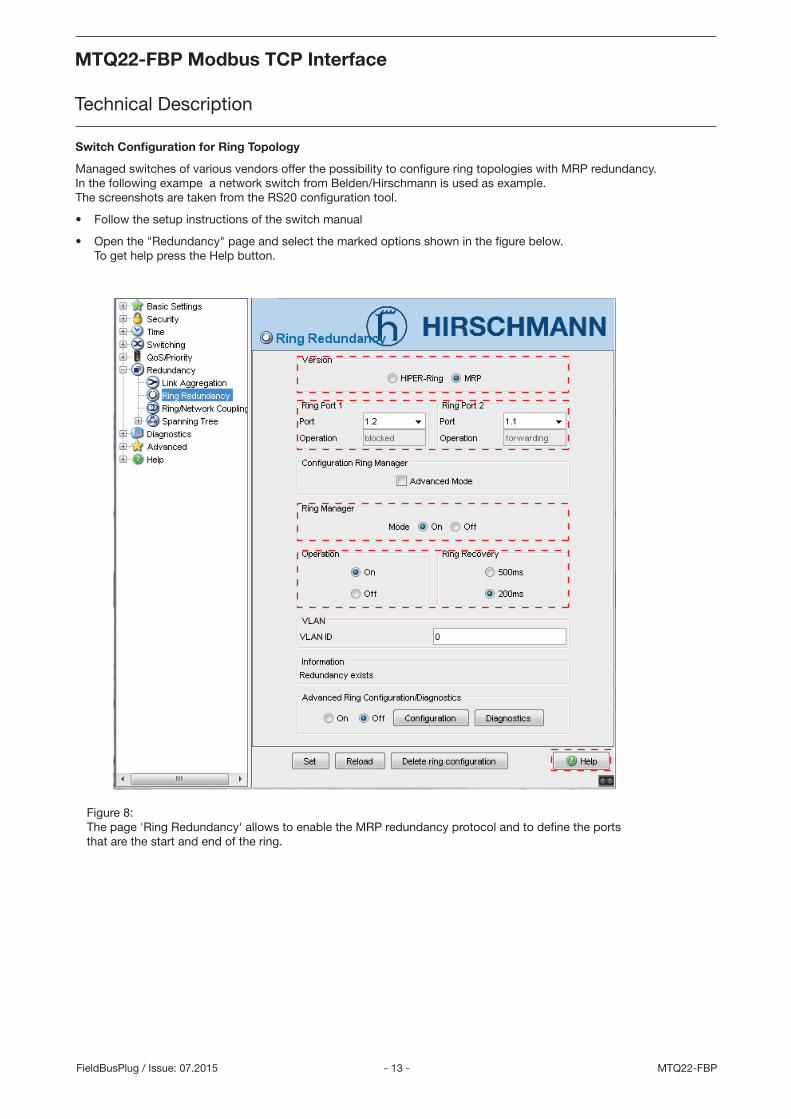
Switch Configuration for Ring Topology
Managed switches of various vendors offer the possibility to configure ring topologies with MRP redundancy. In the following exampe a network switch from Belden/Hirschmann is used as example. The screenshots are taken from the RS20 configuration tool.
• Follow the setup instructions of the switch manual
• Open the "Redundancy" page and select the marked options shown in the figure below. To get help press the Help button.
Figure 8: The page 'Ring Redundancy' allows to enable the MRP redundancy protocol and to define the ports that are the start and end of the ring.
MTQ22-FBP Modbus TCP Interface
Technical Description
MTQ22-FBP Modbus TCP Interface
Technical Description
- 14 -MTQ22-FBP FieldBusPlug / Issue: 07.2015
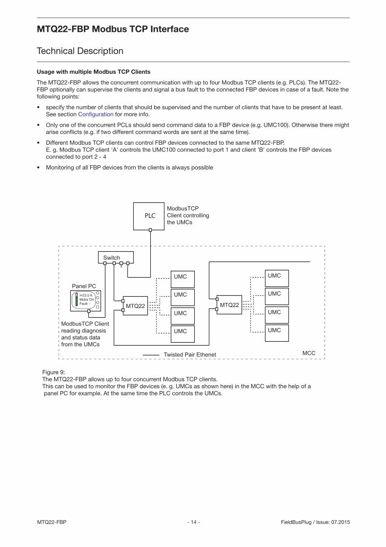
Usage with multiple Modbus TCP Clients
The MTQ22-FBP allows the concurrent communication with up to four Modbus TCP clients (e.g. PLCs). The MTQ22-FBP optionally can supervise the clients and signal a bus fault to the connected FBP devices in case of a fault. Note the following points:
• specify the number of clients that should be supervised and the number of clients that have to be present at least. See section Configuration for more info.
• Only one of the concurrent PCLs should send command data to a FBP device (e.g. UMC100). Otherwise there might arise conflicts (e.g. if two different command words are sent at the same time).
• Different Modbus TCP clients can control FBP devices connected to the same MTQ22-FBP. E. g. Modbus TCP client 'A' controls the UMC100 connected to port 1 and client 'B' controls the FBP devices connected to port 2 - 4
• Monitoring of all FBP devices from the clients is always possible
Switch
MTQ22
UMC
UMC
UMC
UMC
MTQ22
UMC
UMC
UMC
UMC
PLC
MCC
Panel PCI=23.5 A Motor OnFault: -
Twisted Pair Ethenet
ModbusTCPClient controllingthe UMCs
ModbusTCP Clientreading diagnosisand status data from the UMCs
Figure 9: The MTQ22-FBP allows up to four concurrent Modbus TCP clients. This can be used to monitor the FBP devices (e. g. UMCs as shown here) in the MCC with the help of a panel PC for example. At the same time the PLC controls the UMCs.
MTQ22-FBP Modbus TCP Interface
Technical Description
MTQ22-FBP Modbus TCP Interface
Technical Description
- 15 - MTQ22-FBPFieldBusPlug / Issue: 07.2015
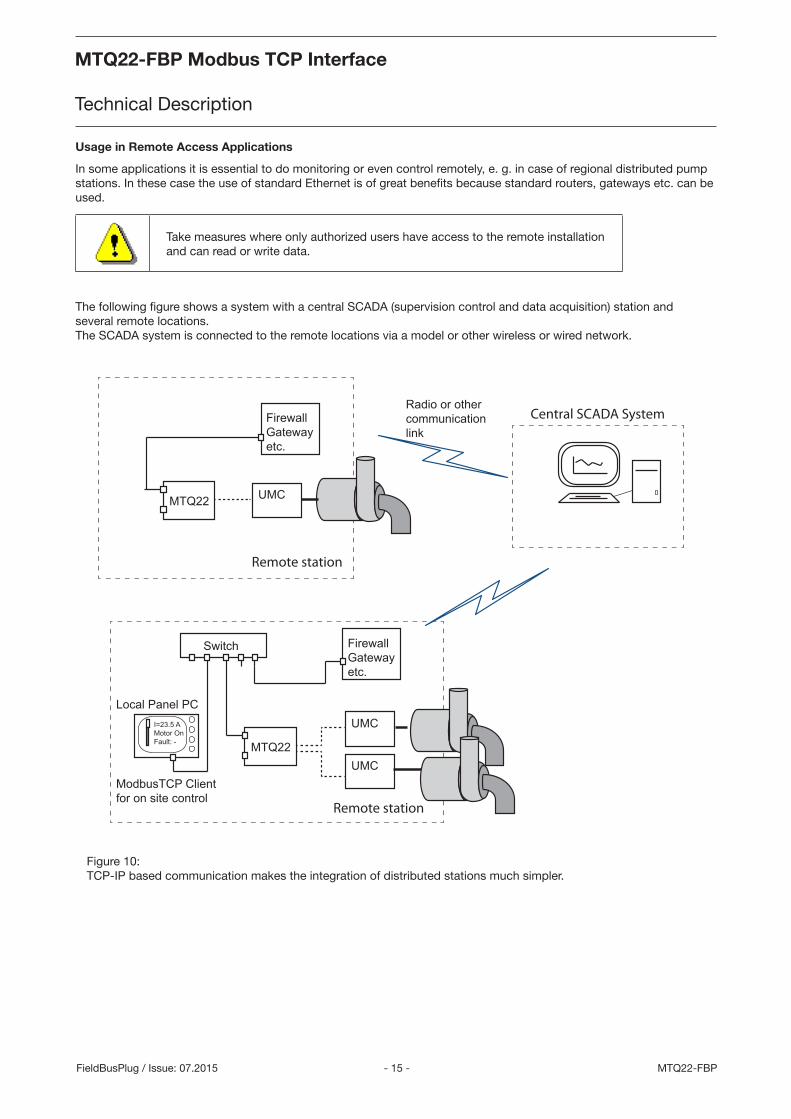
Usage in Remote Access Applications
In some applications it is essential to do monitoring or even control remotely, e. g. in case of regional distributed pump stations. In these case the use of standard Ethernet is of great benefits because standard routers, gateways etc. can be used.
Take measures where only authorized users have access to the remote installation and can read or write data.
The following figure shows a system with a central SCADA (supervision control and data acquisition) station and several remote locations. The SCADA system is connected to the remote locations via a model or other wireless or wired network.
Switch
MTQ22UMC
UMCI=23.5 AMotor OnFault: -
FirewallGatewayetc.
MTQ22 UMC
FirewallGatewayetc.
Radio or other communicationlink
ModbusTCP Clientfor on site control
Local Panel PC
Remote station
Remote station
Central SCADA System
Figure 10: TCP-IP based communication makes the integration of distributed stations much simpler.
MTQ22-FBP Modbus TCP Interface
Technical Description
MTQ22-FBP Modbus TCP Interface
Technical Description
- 16 -MTQ22-FBP FieldBusPlug / Issue: 07.2015
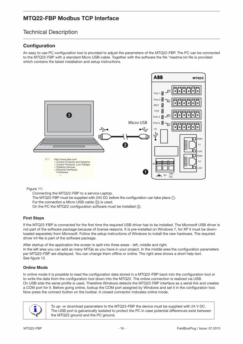
ConfigurationAn easy to use PC configuration tool is provided to adjust the parameters of the MTQ22-FBP. The PC can be connected to the MTQ22-FBP with a standard Micro USB-cable. Together with the software the file "readme.txt file is provided which contains the latest installation and setup instructions.
Micro USB
24VDC0V
Port 1
Port 2
Port 3
RDY
TCP
Link
Data
Link
Data
MTQ22
Port 4
X1
X2
X3
X4
X5
X6
E1
E2
Figure 11: Connecting the MTQ22-FBP to a service Laptop. The MTQ22-FBP must be supplied with 24V DC before the configuration can take place . For the connection a Micro USB cable ) is used. On the PC the MTQ22 configuration software must be installed .
First Steps
If the MTQ22-FBP is connected for the first time the required USB driver has to be installed. The Microsoft USB driver is not part of the software package because of license reasons. It is pre-installed on Windows 7, for XP it must be down-loaded separately from Microsoft. Follow the setup instructions of Windows to install the new hardware. The required driver inf-file is part of the software package.
After startup of the application the screen is split into three areas - left, middle and right. In the left area you can add as many MTQs as you have in your project. In the middle area the configuration parameters per MTQ22-FBP are displayed. You can change them offline or online. The right area shows a short help text. See figure 12.
Online Mode
In online mode it is possible to read the configuration data stored in a MTQ22-FBP back into the configuration tool or to write the data from the configuration tool down into the MTQ22. The online connection is realized via USB. On USB side the serial profile is used. Therefore Windows detects the MTQ22-FBP interface as a serial link and creates a COM port for it. Before going online, lookup the COM port assigned by Windows and set it in the configuration tool. Now press the connect button on the toolbar. A closed connector indicates online mode.
To up- or download parameters to the MTQ22-FBP the device must be supplied with 24 V DC. The USB port is galvanically isolated to protect the PC in case potential differences exist between the MTQ22 ground and the PC ground.
:8 http://www.abb.com> Control Products and Systems> Control Products, Low Voltage> Fieldbus Devices> Ethernet Interfaces O Software ....
MTQ22-FBP Modbus TCP Interface
Technical Description
MTQ22-FBP Modbus TCP Interface
Technical Description
- 17 - MTQ22-FBPFieldBusPlug / Issue: 07.2015
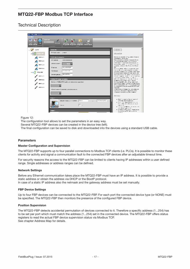
Figure 12: The configuration tool allows to set the parameters in an easy way. Several MTQ22-FBP devices can be created in the device tree (left). The final configuration can be saved to disk and downloaded into the devices using a standard USB cable.
Parameters
Master Configuration and Supervision
The MTQ22-FBP supports up to four parallel connections to Modbus TCP clients (i.e. PLCs). It is possible to monitor these clients for activity and signal a communication fault to the connected FBP devices after an adjustable timeout time.
For security reasons the access to the MTQ22-FBP can be limited to clients having IP addresses within a user defined range. Single addresses or address ranges can be defined.
Network Settings
Before any Ethernet communication takes place the MTQ22-FBP must have an IP address. It is possible to provide a static address or obtain the address via DHCP or the BootP protocol. In case of a static IP address also the netmask and the gateway address must be set manually.
FBP Device Settings
Up to four FBP devices can be connected to the MTQ22-FBP. For each port the connected device type (or NONE) must be specified. The MTQ22-FBP then monitors the presence of the configured FBP device.
Position Supervision
The MTQ22-FBP detects accidental permutation of devices connected to it. Therefore a specific address (1...254) has to be set per port which must match the address (1...254) set in the connected device. The MTQ22-FBP offers status registers to read the actual FBP device supervision status via Modbus TCP. See chapter Address Map for details.
MTQ22-FBP Modbus TCP Interface
Technical Description
MTQ22-FBP Modbus TCP Interface
Technical Description
- 18 -MTQ22-FBP FieldBusPlug / Issue: 07.2015
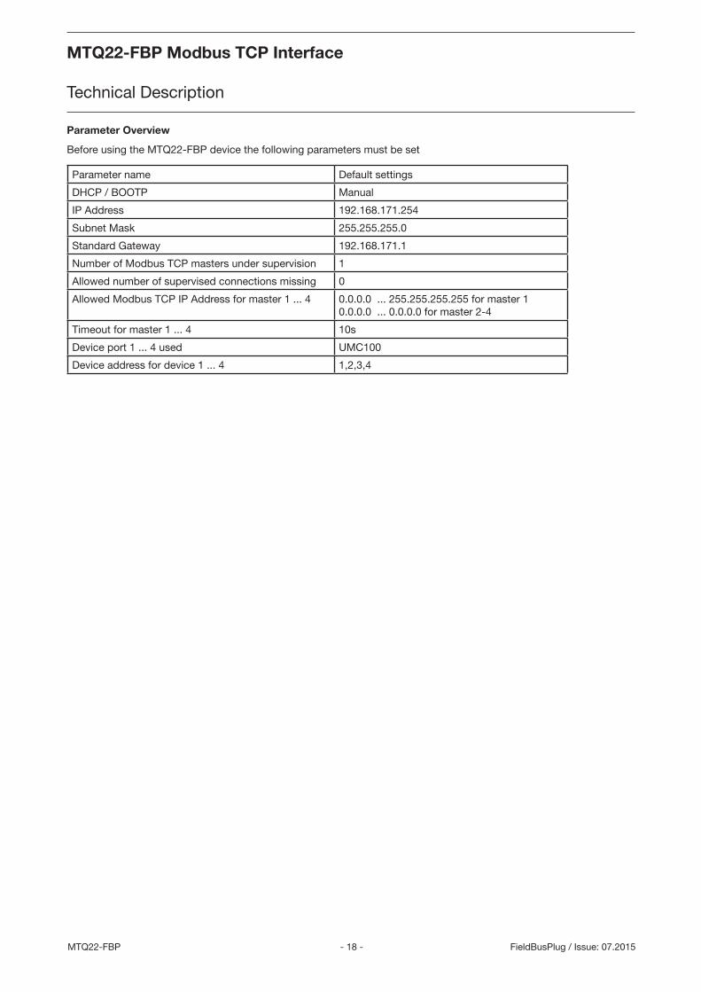
Parameter Overview
Before using the MTQ22-FBP device the following parameters must be set
Parameter name Default settings
DHCP / BOOTP Manual
IP Address 192.168.171.254
Subnet Mask 255.255.255.0
Standard Gateway 192.168.171.1
Number of Modbus TCP masters under supervision 1
Allowed number of supervised connections missing 0
Allowed Modbus TCP IP Address for master 1 ... 4 0.0.0.0 ... 255.255.255.255 for master 10.0.0.0 ... 0.0.0.0 for master 2-4
Timeout for master 1 ... 4 10s
Device port 1 ... 4 used UMC100
Device address for device 1 ... 4 1,2,3,4
MTQ22-FBP Modbus TCP Interface
Technical Description
MTQ22-FBP Modbus TCP Interface
Technical Description
- 19 - MTQ22-FBPFieldBusPlug / Issue: 07.2015
Modbus TCP Register Map
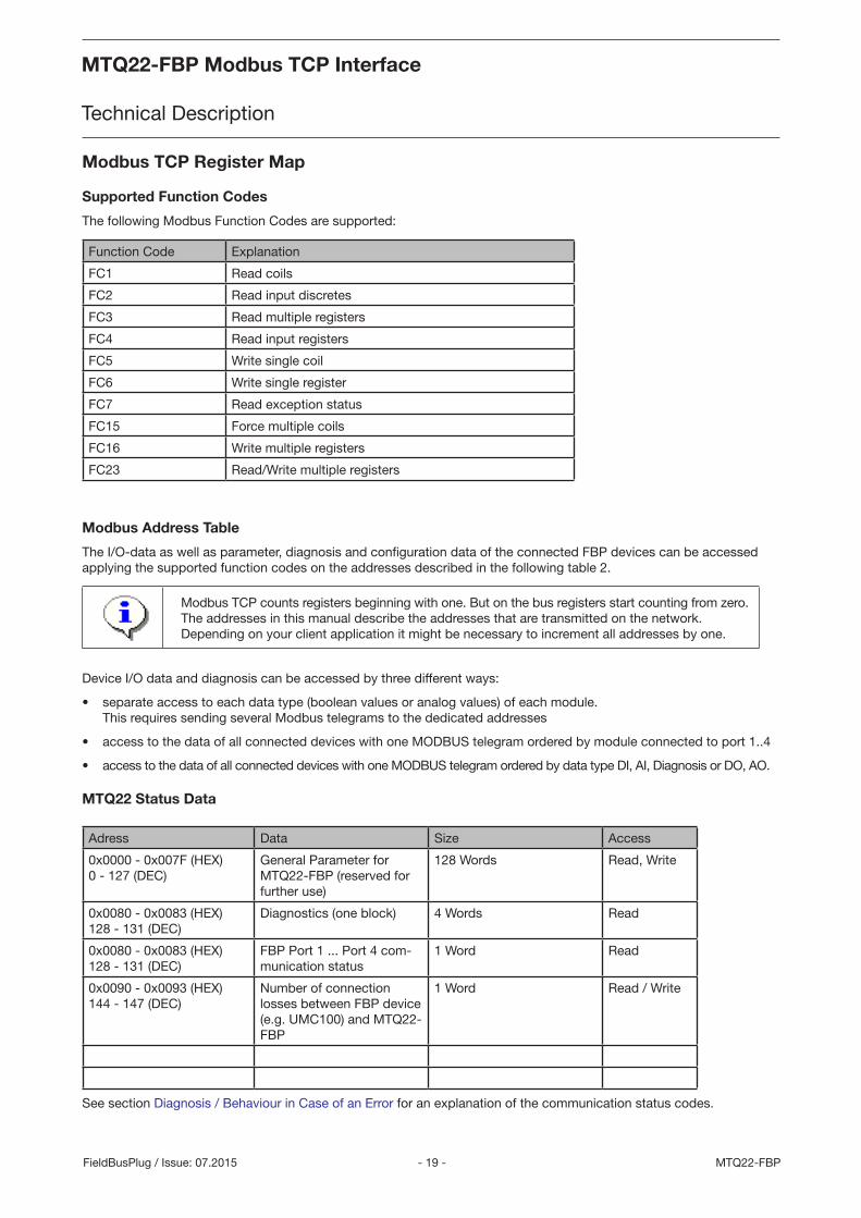
Supported Function Codes
The following Modbus Function Codes are supported:
Function Code Explanation
FC1 Read coils
FC2 Read input discretes
FC3 Read multiple registers
FC4 Read input registers
FC5 Write single coil
FC6 Write single register
FC7 Read exception status
FC15 Force multiple coils
FC16 Write multiple registers
FC23 Read/Write multiple registers
Modbus Address Table
The I/O-data as well as parameter, diagnosis and configuration data of the connected FBP devices can be accessed applying the supported function codes on the addresses described in the following table 2.
Modbus TCP counts registers beginning with one. But on the bus registers start counting from zero. The addresses in this manual describe the addresses that are transmitted on the network. Depending on your client application it might be necessary to increment all addresses by one.
Device I/O data and diagnosis can be accessed by three different ways:
• separate access to each data type (boolean values or analog values) of each module. This requires sending several Modbus telegrams to the dedicated addresses
• access to the data of all connected devices with one MODBUS telegram ordered by module connected to port 1..4
• access to the data of all connected devices with one MODBUS telegram ordered by data type DI, AI, Diagnosis or DO, AO.
MTQ22 Status Data
Adress Data Size Access
0x0000 - 0x007F (HEX)0 - 127 (DEC)
General Parameter for MTQ22-FBP (reserved for further use)
128 Words Read, Write
0x0080 - 0x0083 (HEX)128 - 131 (DEC)
Diagnostics (one block) 4 Words Read
0x0080 - 0x0083 (HEX)128 - 131 (DEC)
FBP Port 1 ... Port 4 com-munication status
1 Word Read
0x0090 - 0x0093 (HEX)144 - 147 (DEC)
Number of connection losses between FBP device (e.g. UMC100) and MTQ22-FBP
1 Word Read / Write
See section Diagnosis / Behaviour in Case of an Error for an explanation of the communication status codes.
MTQ22-FBP Modbus TCP Interface
Technical Description
MTQ22-FBP Modbus TCP Interface
Technical Description
- 20 -MTQ22-FBP FieldBusPlug / Issue: 07.2015
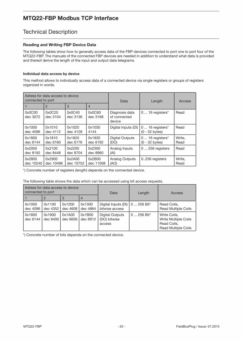
Reading and Writing FBP Device Data
The following tables show how to generally access data of the FBP-devices connected to port one to port four of the MTQ22-FBP. The manuals of the connected FBP devices are needed in addition to understand what data is provided and thereof derive the length of the input and output data telegrams.
Individual data access by device
This method allows to individually access data of a connected device via single registers or groups of registers organized in words.
Adress for data access to device connected to port Data Length Access1 2 3 4
0x0C00dec 3072
0x0C20dec 3104
0x0C40dec 3136
0x0C60dec 3168
Diagnosis data of connected device
0 ... 16 registers* Read
0x1000dec 4096
0x1010dec 4112
0x1020dec 4128
0x10304144
Digital Inputs (DI) 0 ... 16 registers* (0 - 32 bytes)
Read
0x1800dec 6144
0x1810dec 6160
0x1820dec 6176
0x1830dec 6192
Digital Outputs (DO)
0 ... 16 registers* (0 - 32 bytes)
Write, Read
0x2000dec 8192
0x2100dec 8448
0x2200dec 8704
0x2300dec 8960
Analog Inputs (AI)
0 ... 256 registers Read
0x2800dec 10240
0x2900dec 10496
0x2A00dec 10752
0x2B00dec 11008
Analog Outputs (AO)
0..256 registers Write, Read
*) Concrete number of registers (length) depends on the connected device.
The following table shows the data which can be accessed using bit access requests.
Adress for data access to device connected to port Data Length Access1 2 3 4
0x1000dec 4096
0x1100dec 4352
0x1200dec 4608
0x1300dec 4864
Digital Inputs (DI) bitwise access
0 ... 256 Bit* Read Coils,Read Multiple Coils
0x1800dec 6144
0x1900dec 6400
0x1A00dec 6656
0x1B00dec 6912
Digital Outputs (DO) bitwise access
0 ... 256 Bit* Write Coils,Write Multiple CoilsRead Coils,Read Multiple Coils
*) Concrete number of bits depends on the connected device.
MTQ22-FBP Modbus TCP Interface
Technical Description
MTQ22-FBP Modbus TCP Interface
Technical Description
- 21 - MTQ22-FBPFieldBusPlug / Issue: 07.2015
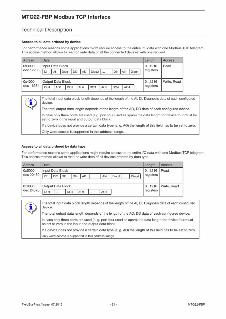
Access to all data ordered by device
For performance reasons some applications might require access to the entire I/O data with one Modbus TCP telegram. This access method allows to read or write data of all the connected devices with one request.
Adress Data Length Access
0x3000dec 12288
Input Data Block
DI1 AI1 Diag1 DI2 AI2 Diag2 ... DI4 AI4 Diag4
0...1216 registers
Read
0x4000dec 16384
Output Data Block
DO1 AO1 DO2 AO2 DO3 AO3 DO4 AO4
0...1216 registers
Write, Read
The total input data block length depends of the length of the AI, DI, Diagnosis data of each configured device.
The total output data length depends of the length of the AO, DO data of each configured device.
In case only three ports are used (e.g. port four used as spare) the data length for device four must be set to zero in the input and output data block.
If a device does not provide a certain data type (e. g. AO) the length of this field has to be set to zero.
Only word access is supported in this address range.
Access to all data ordered by data type
For performance reasons some applications might require access to the entire I/O data with one Modbus TCP telegram. This access method allows to read or write data of all devices ordered by data type
Adress Data Length Access
0x5000dec 20480
Input Data Block
DI1 DI2 DI3 DI4 AI1 ... AI4 Diag1 ... Diag4
0...1216registers
Read
0x6000dec 24576
Output Data Block
DO1 ... DO4 AO1 ... AO4
0...1216registers
Write, Read
The total input data block length depends of the length of the AI, DI, Diagnosis data of each configured device.
The total output data length depends of the length of the AO, DO data of each configured device.
In case only three ports are used (e. g. port four used as spare) the data length for device four must be set to zero in the input and output data block.
If a device does not provide a certain data type (e. g. AO) the length of this field has to be set to zero.
Only word access is supported in this address range
MTQ22-FBP Modbus TCP Interface
Technical Description
MTQ22-FBP Modbus TCP Interface
Technical Description
- 22 -MTQ22-FBP FieldBusPlug / Issue: 07.2015
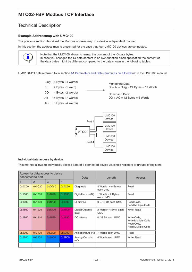
Example Addressmap with UMC100
The previous section described the Modbus address map in a device independant manner.
In this section the address map is presented for the case that four UMC100 devices are connected.
Note that the UMC100 allows to remap the content of the IO data bytes. In case you changed the IO data content in an own function block application the content of the data bytes might be different compared to the data shown in the following tables.
UMC100-I/O data referrred to in section A1 Parameters and Data Structures on a Fieldbus: in the UMC100 manual
Individual data access by device
This method allows to individually access data of a connected device via single registers or groups of registers.
Adress for data access to device connected to port Data Length Access1 2 3 4
0x0C00 0x0C20 0x0C40 0x0C60 Diagnosis 4 Words ( = 8 Bytes)each UMC
Read
0x1000 0x1010 0x1020 0x1030 Digital Inputs (DI) 1 Word ( = 2 Bytes) each UMC
Read
0x1000 0x1100 0x1200 0x1300 DI bitwise 0 ... 16 Bit each UMC Read Coils,Read Multiple Coils
0x1800 0x1900 0x1A00 0x1B00 Digital Outputs (DO)
2 Word (= 4 Byte) each UMC
Write, Read
0x1800 0x1810 0x1820 0x1830 DO bitwise 0..32 Bit each UMC Write Coils,Write Multiple CoilsRead Coils,Read Multiple Coils
0x2000 0x2100 0x2200 0x2300 Analog Inputs (AI) 7 Words each UMC Read
0x2800 0x2900 0x2A00 0x2B00 Analog Outputs (AO)
4 Words each UMC Write, Read
MTQ22
UMC100Device
UMC100Device
UMC100Device
UMC100Device
Port 1
Port 4
Diag: 8 Bytes (4 Words)
DI: 2 Bytes (1 Word)
DO: 4 Bytes (2 Words)
AI: 14 Bytes (7 Words)
AO: 8 Bytes (4 Words)
Monitoring Data:DI + AI + Diag = 24 Bytes = 12 Words
Command Data:DO + AO = 12 Bytes = 6 Words
MTQ22-FBP Modbus TCP Interface
Technical Description
MTQ22-FBP Modbus TCP Interface
Technical Description
- 23 - MTQ22-FBPFieldBusPlug / Issue: 07.2015
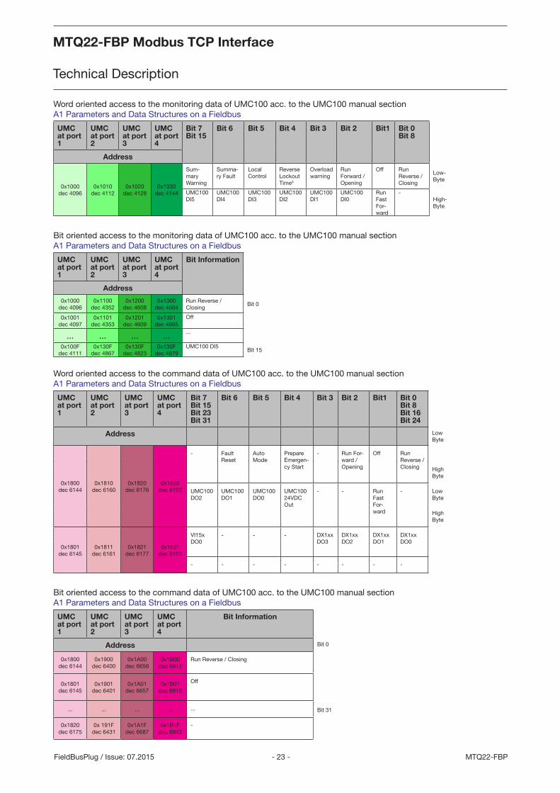
Word oriented access to the monitoring data of UMC100 acc. to the UMC100 manual section A1 Parameters and Data Structures on a Fieldbus
UMC at port 1
UMC at port 2
UMC at port 3
UMC at port 4
Bit 7 Bit 15
Bit 6 Bit 5 Bit 4 Bit 3 Bit 2 Bit1 Bit 0 Bit 8
Address
0x1000dec 4096
0x1010dec 4112
0x1020dec 4128
0x1030dec 4144
Sum-mary Warning
Summa-ry Fault
Local Control
Reverse Lockout Time3
Overload warning
Run Forward / Opening
Off Run Reverse / Closing
Low-Byte
UMC100 DI5
UMC100 DI4
UMC100 DI3
UMC100 DI2
UMC100 DI1
UMC100 DI0
Run Fast For-ward
-High-Byte
Bit oriented access to the monitoring data of UMC100 acc. to the UMC100 manual section A1 Parameters and Data Structures on a Fieldbus
UMC at port 1
UMC at port 2
UMC at port 3
UMC at port 4
Bit Information
Address
0x1000dec 4096
0x1100dec 4352
0x1200dec 4608
0x1300dec 4864
Run Reverse / Closing
Bit 0
0x1001dec 4097
0x1101dec 4353
0x1201dec 4609
0x1301dec 4865
Off
... ... ... ... ...
0x100Fdec 4111
0x130Fdec 4867
0x130F dec 4823
0x130Fdec 4879
UMC100 DI5Bit 15
Word oriented access to the command data of UMC100 acc. to the UMC100 manual section A1 Parameters and Data Structures on a Fieldbus
UMC at port 1
UMC at port 2
UMC at port 3
UMC at port 4
Bit 7 Bit 15 Bit 23 Bit 31
Bit 6 Bit 5 Bit 4 Bit 3 Bit 2 Bit1 Bit 0 Bit 8 Bit 16 Bit 24
Address Low Byte
0x1800dec 6144
0x1810dec 6160
0x1820dec 6176
0x1830dec 6192
- Fault Reset
Auto Mode
Prepare Emergen-cy Start
- Run For-ward / Opening
Off Run Reverse / Closing High
Byte
UMC100 DO2
UMC100 DO1
UMC100 DO0
UMC100 24VDC Out
- - Run Fast For-ward
- Low Byte
High Byte
0x1801dec 6145
0x1811dec 6161
0x1821dec 6177
0x1831dec 6193
VI15x DO0
- - - DX1xx DO3
DX1xx DO2
DX1xx DO1
DX1xx DO0
- - - - - - - -
Bit oriented access to the command data of UMC100 acc. to the UMC100 manual section A1 Parameters and Data Structures on a Fieldbus
UMC at port 1
UMC at port 2
UMC at port 3
UMC at port 4
Bit Information
Address Bit 0
0x1800dec 6144
0x1900dec 6400
0x1A00dec 6656
0x1B00dec 6912
Run Reverse / Closing
0x1801dec 6145
0x1901dec 6401
0x1A01dec 6657
0x1B01dec 6913
Off
... ... ... ... ... Bit 31
0x1820dec 6175
0x 191Fdec 6431
0x1A1Fdec 6687
0x1B1Fdec 6943
-
MTQ22-FBP Modbus TCP Interface
Technical Description
MTQ22-FBP Modbus TCP Interface
Technical Description
- 24 -MTQ22-FBP FieldBusPlug / Issue: 07.2015
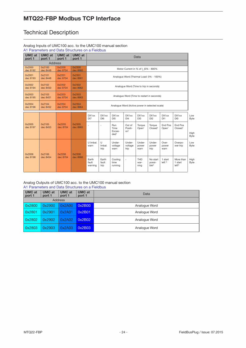
Analog Inputs of UMC100 acc. to the UMC100 manual section A1 Parameters and Data Structures on a Fieldbus UMC at port 1
UMC at port 1
UMC at port 1
UMC at port 1 Data
Address0x2000dec 8192
0x2100dec 8448
0x2200dec 8704
0x2300dec 8960
Motor Current in % of Ie (0% - 800%
0x2001dec 8193
0x2101dec 8448
0x2201dec 8704
0x2301dec 8961
Analogue Word (Thermal Load: 0% - 100%)
0x2002dec 8194
0x2102dec 8450
0x2202dec 8704
0x2302dec 8962
Analogue Word (Time to trip in seconds)
0x2003dec 8195
0x2103dec 8451
0x2203dec 8704
0x2303dec 8963
Analogue Word (Time to restart in seconds)
0x2004dec 8196
0x2104dec 8452
0x2204dec 8704
0x2304dec 8964
Analogue Word (Active power in selected scale)
0x2005dec 8197
0x2105dec 8453
0x2205dec 8704
0x2305dec 8965
DX1xx DI7
DX1xx DI6
DX1xx DI5
DX1xx DI4
DX1xx DI3
DX1xx DI2
DX1xx DI1
DX1xx DI0
Low Byte
- - Run Time Excee-ded1
Out of Positi-on1
Torque Open1
Torque Closed1
End Pos Open1
End Pos Closed1
High Byte
0x2006dec 8198
0x2106dec 8454
0x2206dec 8704
0x2306dec 8966
U Imbal. warn
U Imbal. trip
Under-voltage warn
Under-voltage trip
Under-power warn
Under-power trip
Over-power warn
Overpo-wer trip
Low Byte
Earth fault warning
Earth fault trip
Cooling time running
- THD war-ning
No start possi-ble5)
1 start left 5)
More than 1 start left5)
High Byte
Analog Outputs of UMC100 acc. to the UMC100 manual section A1 Parameters and Data Structures on a Fieldbus UMC at port 1
UMC at port 1
UMC at port 1
UMC at port 1 Data
Address
0x2800 0x2900 0x2A00 0x2B00 Analogue Word
0x2801 0x2901 0x2A01 0x2B01 Analogue Word
0x2802 0x2902 0x2A02 0x2B02 Analogue Word
0x2803 0x2903 0x2A03 0x2B03 Analogue Word

MTQ22-FBP Modbus TCP Interface
Technical Description
MTQ22-FBP Modbus TCP Interface
Technical Description
- 25 - MTQ22-FBPFieldBusPlug / Issue: 07.2015
UMC at port 1
UMC at port 2
UMC at port 3
UMC at port 4
Bit 7 Bit 6 Bit 5 Bit 4 Bit 3 Bit 2 Bit1 Bit 0
Adress
0x0C00
dec 3072
0x0C20
dec 3104
0x0C40
dec 3136
0x0C60
dec 3168
Check-back missing
PTC wiring failure
PTC hot Pre-waring thermal model
Locked ro-tor during start-up (stall)
Phase im-balance1
Phase loss1
Thermal overload trip
Actuator problem1
UMC self-test error
Earth fault pre-warning
Eart fault trip (internal or externally triggered)
I above high current warning threshold
I above high cur-rent trip threshold
I below low current warning thresh-old
I below low current trip threshold
0x0C01
dec 3073
0xC021
dec 3105
0x0C41
dec 3137
0x0C61
dec 3167
Trip/Warn-ing from AuxFault function block input 52)
Trip/Warn-ing from AuxFault function block input 42)
Trip/Warn-ing from AuxFault function block input 32)
Trip/Warn-ing from AuxFault function block input 22)
Trip/Warn-ing from AuxFault function block input 12)
HW fault on IO module
Custom applica-tion error
IO module missing
- - - - Trip trig-gered from Multifunc-tion input DI2
Trip trig-gered from Multifunc-tion input DI1
Trip trig-gered from Multi-function input DI0
Trip / Warn-ing from AuxFault function block input 62)
0x0C02
dec 3074
0x0C22
dec 3106
0x0C42
dec 3138
0x0C62
dec 3168
- - THD Warning
Voltage out of spec1
Overload power
Underload power1
- -
- - Cooling Time Running
Just one start left
Num Starts Overrun
- - -
0x0C03
dec 3075
0x0C23
dec 3107
0x0C43
dec 3139
0x0C63
dec 3169
Extended diagnosis is avail-able1).
Param-eter out of range
- - - - - -
Fault code. See section "Error Handling, Maintenance and Service-> Fault Messages" for a description of the code.
Diagnosis Data of UMC100 according to the UMC100 manual section A1 Parameters and Data Structures on a Fieldbus
MTQ22-FBP Modbus TCP Interface
Technical Description
MTQ22-FBP Modbus TCP Interface
Technical Description
- 26 -MTQ22-FBP FieldBusPlug / Issue: 07.2015
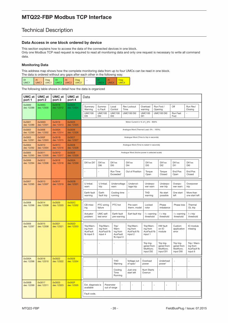
Data Access in one block ordered by device
This section explains how to access the data of the connected devices in one block. Only one Modbus TCP read request is required to read all monitoring data and only one request is necessary to write all command data.
Monitoring Data
This address map shows how the complete monitoring data from up to four UMCs can be read in one block. The data is ordered without any gaps after each other in the followng way.
DI UMC1
AI UMC1
DiagUMC1
DIUMC2
AIUMC2
DiagUMC2
... DIUMC4
AIUMC4
DiagUMC4
The following table shows in detail how the data is organized
UMC at port 1
UMC at port 2
UMC at port 3
UMC at port 4
Data
0x3000dec 12288
0x300Cdec 12300
0x3018dec 12312
0x3024dec 12324 Summary
WarningSumma-ry Fault
Local Control
Rev Lockout Time
Overload warning
Run Fwd / Opening
Off Run Rev/ Closing
UMC100 DI5
UMC100 DI4
UMC100 DI3
UMC100 DI2 UMC100 DI1
UMC100 DI0 Run Fast Fwd
-
0x3001dec 12289
0x300Ddec 12301
0x3019dec 12313
0x3025dec 12325
Motor Current in % of Ie (0% - 800%
0x3002dec 12290
0x300Edec 12302
0x300Adec 12314
0x3026dec 12326
Analogue Word (Thermal Load: 0% - 100%)
0x3003dec 12291
0x300Fdec 12303
0x301Bdec 12315
0x3027dec 12327
Analogue Word (Time to trip in seconds)
0x3004dec 12292
0x3010dec 12304
0x301Cdec 12316
0x3028dec 12328
Analogue Word (Time to restart in seconds)
0x3005dec 12293
0x3011dec 12305
0x301Ddec 12317
0x3029dec 12329
Analogue Word (Active power in selected scale)
0x3006dec 12294
0x3012dec 12306
0x301Edec 12318
0x302Adec 12330 DX1xx DI7 DX1xx
DI6DX1xx DI5
DX1xx DI4
DX1xx DI3
DX1xx DI2
DX1xx DI1
DX1xx DI0
- - Run Time Exceeded1
Out of Position Torque Open
Torque Closed
End Pos Open
End Pos Closed
0x3007dec 12295
0x3013dec 12307
0x301Fdec 12319
0x302Bdec 12331 U Imbal.
warnU Imbal. trip
Undervoltage warn
Undervol-tage trip
Underpo-wer warn
Underpo-wer trip
Overpo-wer warn
Overpower trip
Earth fault warning
Earth fault trip
Cooling time running
- THD warning
No start possible
One start left
More than one start left
0x3008dec 12296
0x3014dec 12308
0x3020dec 12320
0x302Cdec 12332 CB miss-
ingPTC wiring failure
PTC hot Pre-warn therm. model
Locked rotor
Phase imbalance
Phase loss Thermal OL trip
Actuator problem
UMC self-test error
Earth fault pre-warning
Eart fault trip I > warning threshold
I > trip threshold
I < warning threshold
I < trip threshold
0x3009dec 12297
0x3015dec 12308
0x3021dec 12321
0x302Ddec 12333 Trip/Warn-
ing from AuxFault fb input 5
Trip/Warn-ing from AuxFault fb input 4
Trip/Warn-ing from AuxFault fb input 3
Trip/Warn-ing from AuxFault fb input 2
Trip/Warn-ing from AuxFault fb input 1
HW fault on IO module
Custom application error
IO module missing
- - - - Trip trig-gered from Multifunc. input DI2
Trip trig-gered from Multifunc. input DI1
Trip trig-gered from Multifunc. input DI0
Trip / Warn-ing from AuxFault fb input 6
0x300A dec 12298
0x3016dec 12310
0x3022dec 12322
0x302Edec 12334 - - THD
WarningVoltage out of spec1
Overload power
Underload power1
- -
- - Cooling Time Running
Just one start left
Num Starts Overrun
- - -
0x300B dec 12299
0x3017dec 12311
0x3023dec 12323
0x302Fdec 12335 Ext. diagnosis is
availableParameter out of range
- - - - - -
Fault code.
MTQ22-FBP Modbus TCP Interface
Technical Description
MTQ22-FBP Modbus TCP Interface
Technical Description
- 27 - MTQ22-FBPFieldBusPlug / Issue: 07.2015
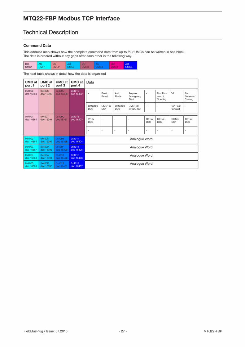
Command Data
This address map shows how the complete command data from up to four UMCs can be written in one block. The data is ordered without any gaps after each other in the followng way.
DOUMC1
AOUMC1
DOUMC2
AOUMC2
DOUMC3
AOUMC3
DOUMC4
AOUMC4
The next table shows in detail how the data is organized
UMC at port 1
UMC at port 2
UMC at port 3
UMC at port 4
Data
0x4000dec 16384
0x4006dec 16390
0x400Cdec 16396
0x4012dec 16402 - Fault
ResetAuto Mode
Prepare Emergency Start
- Run For-ward / Opening
Off Run Reverse / Closing
UMC100 DO2
UMC100 DO1
UMC100 DO0
UMC100 24VDC Out
- - Run Fast Forward
-
0x4001dec 16385
0x4007dec 16391
0x400Ddec 16397
0x4013dec 16403 VI15x
DO0 - - - DX1xx
DO3DX1xx DO2
DX1xx DO1
DX1xx DO0
- - - - - - - -
0x4002dec 16386
0x4008dec 16392
0x400Edec 16398
0x4014dec 16404
Analogue Word
0x4003dec 16387
0x4009dec 16393
0x400Fdec 16399
0x4015dec 16405
Analogue Word
0x4004dec 16388
0x400Adec 16394
0x4010dec 16400
0x4016dec 16406
Analogue Word
0x4005dec 16389
0x400Bdec 16395
0x4011dec 16401
0x4017dec 16407
Analogue Word
MTQ22-FBP Modbus TCP Interface
Technical Description
MTQ22-FBP Modbus TCP Interface
Technical Description
- 28 -MTQ22-FBP FieldBusPlug / Issue: 07.2015
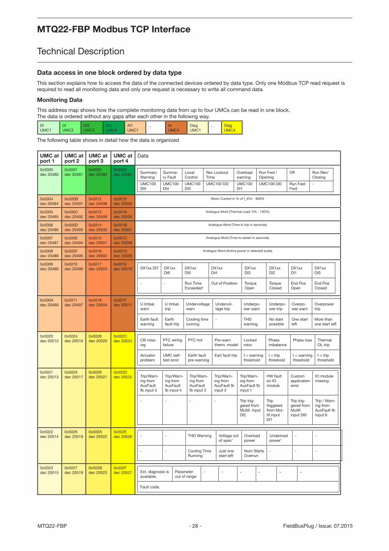
Data access in one block ordered by data type
This section explains how to access the data of the connected devices ordered by data type. Only one Modbus TCP read request is required to read all monitoring data and only one request is necessary to write all command data.
Monitoring Data
This address map shows how the complete monitoring data from up to four UMCs can be read in one block. The data is ordered without any gaps after each other in the followng way.
DIUMC1
DIUMC2
DI3UMC3
DI4UMC4
AI1UMC1
... AIUMC4
DiagUMC1
... DiagUMC4
The following table shows in detail how the data is organized
UMC at port 1
UMC at port 2
UMC at port 3
UMC at port 4
Data
0x5000dec 20480
0x5001dec 20481
0x5002dec 20482
0x5003dec 20483 Summary
WarningSumma-ry Fault
Local Control
Rev Lockout Time
Overload warning
Run Fwd / Opening
Off Run Rev/ Closing
UMC100 DI5
UMC100 DI4
UMC100 DI3
UMC100 DI2 UMC100 DI1
UMC100 DI0 Run Fast Fwd
-
0x5004dec 20484
0x500Bdec 20491
0x5012dec 20498
0x5019dec 20505
Motor Current in % of Ie (0% - 800%
0x5005dec 20485
0x500Cdec 20492
0x5013dec 20499
0x501Adec 20506
Analogue Word (Thermal Load: 0% - 100%)
0x5006dec 20486
0x500Ddec 20493
0x5014dec 20500
0x501Bdec 20507
Analogue Word (Time to trip in seconds)
0x5007dec 20487
0x500Edec 20494
0x5015dec 20501
0x501Cdec 20508
Analogue Word (Time to restart in seconds)
0x5008dec 20488
0x500Fdec 20495
0x5016dec 20502
0x501Ddec 20509
Analogue Word (Active power in selected scale)
0x5009dec 20489
0x5010dec 20496
0x5017dec 20503
0x501Edec 20510 DX1xx DI7 DX1xx
DI6DX1xx DI5
DX1xx DI4
DX1xx DI3
DX1xx DI2
DX1xx DI1
DX1xx DI0
- - Run Time Exceeded1
Out of Position Torque Open
Torque Closed
End Pos Open
End Pos Closed
0x500Adec 20490
0x5011dec 20497
0x5018dec 20504
0x501Fdec 20511 U Imbal.
warnU Imbal. trip
Undervoltage warn
Undervol-tage trip
Underpo-wer warn
Underpo-wer trip
Overpo-wer warn
Overpower trip
Earth fault warning
Earth fault trip
Cooling time running
- THD warning
No start possible
One start left
More than one start left
0x5020dec 20512
0x5024dec 20516
0x5028dec 20520
0x502Cdec 20524 CB miss-
ingPTC wiring failure
PTC hot Pre-warn therm. model
Locked rotor
Phase imbalance
Phase loss Thermal OL trip
Actuator problem
UMC self-test error
Earth fault pre-warning
Eart fault trip I > warning threshold
I > trip threshold
I < warning threshold
I < trip threshold
0x5021dec 20513
0x5025dec 20517
0x5029dec 20521
0x502Ddec 20525 Trip/Warn-
ing from AuxFault fb input 5
Trip/Warn-ing from AuxFault fb input 4
Trip/Warn-ing from AuxFault fb input 3
Trip/Warn-ing from AuxFault fb input 2
Trip/Warn-ing from AuxFault fb input 1
HW fault on IO module
Custom application error
IO module missing
- - - - Trip trig-gered from Multif. input DI2
Trip triggered from Mul-tif.input DI1
Trip trig-gered from Multif. input DI0
Trip / Warn-ing from AuxFault fb input 6
0x5022dec 20514
0x5026dec 20518
0x502Adec 20522
0x502Edec 20526 - - THD Warning Voltage out
of spec1
Overload power
Underload power1
- -
- - Cooling Time Running
Just one start left
Num Starts Overrun
- - -
0x5023dec 20515
0x5027dec 20519
0x502Bdec 20523
0x502Fdec 20527 Ext. diagnosis is
available. Parameter out of range
- - - - - -
Fault code.
MTQ22-FBP Modbus TCP Interface
Technical Description
MTQ22-FBP Modbus TCP Interface
Technical Description
- 29 - MTQ22-FBPFieldBusPlug / Issue: 07.2015
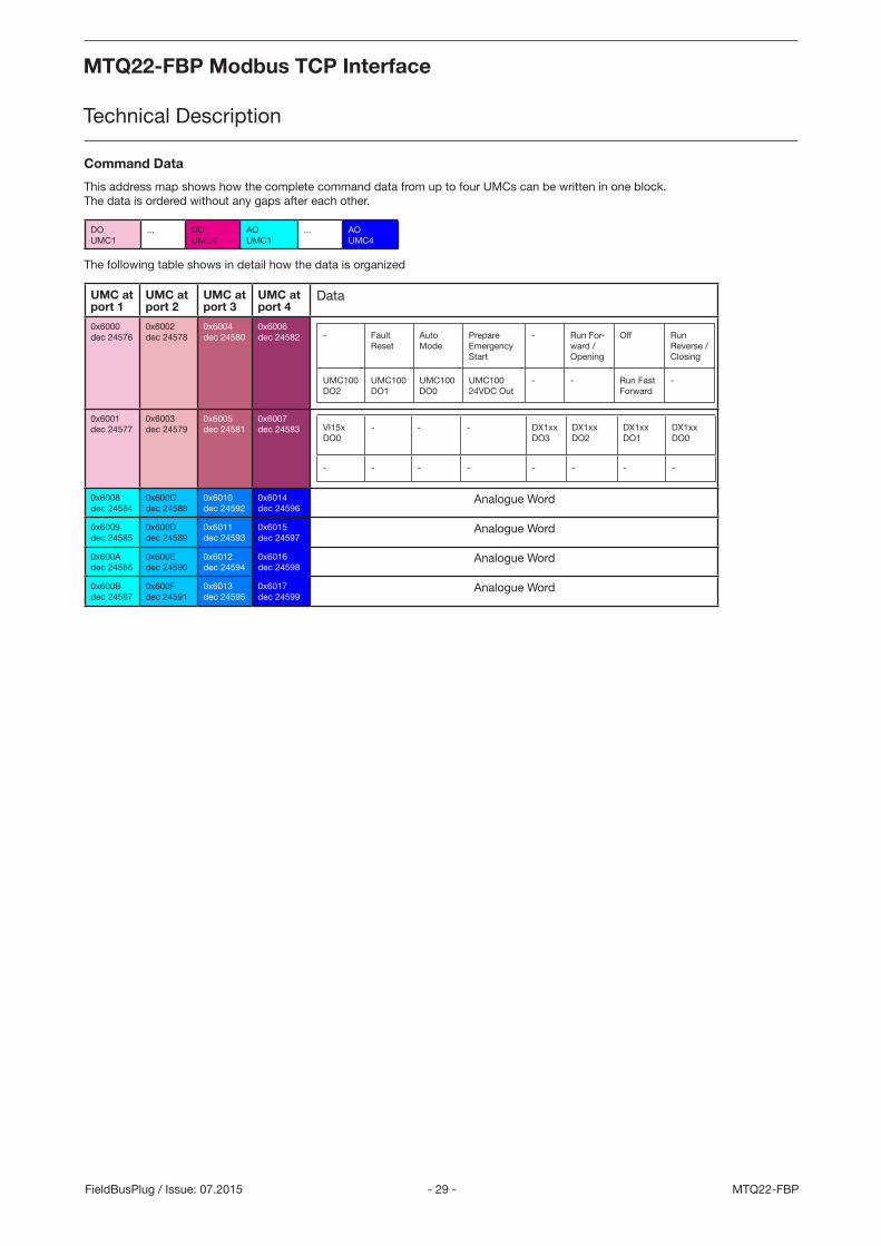
Command Data
This address map shows how the complete command data from up to four UMCs can be written in one block. The data is ordered without any gaps after each other.
DOUMC1
... DOUMC4
AOUMC1
... AOUMC4
The following table shows in detail how the data is organized
UMC at port 1
UMC at port 2
UMC at port 3
UMC at port 4
Data
0x6000dec 24576
0x6002dec 24578
0x6004dec 24580
0x6006dec 24582 - Fault
ResetAuto Mode
Prepare Emergency Start
- Run For-ward / Opening
Off Run Reverse / Closing
UMC100 DO2
UMC100 DO1
UMC100 DO0
UMC100 24VDC Out
- - Run Fast Forward
-
0x6001dec 24577
0x6003dec 24579
0x6005dec 24581
0x6007dec 24583 VI15x
DO0 - - - DX1xx
DO3DX1xx DO2
DX1xx DO1
DX1xx DO0
- - - - - - - -
0x6008dec 24584
0x600Cdec 24588
0x6010dec 24592
0x6014dec 24596
Analogue Word
0x6009dec 24585
0x600Ddec 24589
0x6011dec 24593
0x6015dec 24597
Analogue Word
0x600Adec 24586
0x600Edec 24590
0x6012dec 24594
0x6016dec 24598
Analogue Word
0x600Bdec 24587
0x600Fdec 24591
0x6013dec 24595
0x6017dec 24599
Analogue Word
MTQ22-FBP Modbus TCP Interface
Technical Description
MTQ22-FBP Modbus TCP Interface
Technical Description
- 30 -MTQ22-FBP FieldBusPlug / Issue: 07.2015
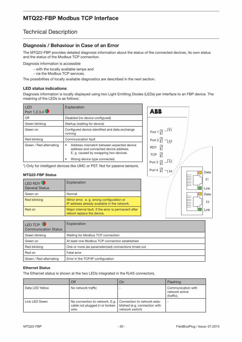
Diagnosis / Behaviour in Case of an ErrorThe MTQ22-FBP provides detailed diagnosis information about the status of the connected devices, its own status and the status of the Modbus TCP connection.
Diagnosis information is accessible
- with the locally available lamps and- via the Modbus TCP services.
The possibilities of locally available diagnostics are described in the next section.
LED status indicationsDiagnosis information is locally displayed using two Light Emitting Diodes (LEDs) per interface to an FBP device. The meaning of the LEDs is as follows:
LED Port 1,2,3,4
Explanation
Off Disabled (no device configured)
Green blinking Startup (waiting for device)
Green on Configured device identified and data exchange running
Red blinking Communication fault
Green / Red alternating • Address mismatch between expected device address and connected device address. E. g. caused by swapping two devices.
• Wrong device type connected.
*) Only for intelligent devices like UMC or PST. Not for passive sensors.
MTQ22-FBP Status
LED RDY General Status
Explanation
Green on Normal
Red blinking Minor error, e. g. wrong configuration or IP address already available in the network.
Red on Major internal fault. If the error is permanent after reboot replace the device.
LED TCP Communication Status
Explanation
Green blinking Waiting for Modbus TCP connection
Green on At least one Modbus TCP connection established
Red blinking One or more (as parameterized) connections timed out
Red on Fatal error
Green / Red alternating Error in the TCP/IP configuration
Ethernet Status
The Ethernet status is shown at the two LEDs integrated in the RJ45 connectors.
Off On Flashing
Data LED Yellow No network traffic - Communication with network active (traffic).
Link LED Green No connection to network. E.g. cable not plugged in or broken wire.
Connection to network esta-blished (e.g. connection with network switch)
-
Port 1
Port 2
Port 3
RDY
TCP
Link
Data
Link
Data
Port 4
E2
E1
X1
X2
X3
X4
MTQ22-FBP Modbus TCP Interface
Technical Description
MTQ22-FBP Modbus TCP Interface
Technical Description
- 31 - MTQ22-FBPFieldBusPlug / Issue: 07.2015
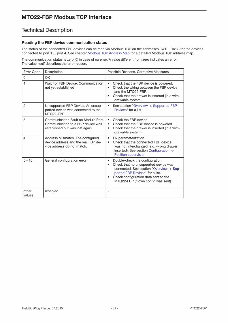
Reading the FBP device communication status
The status of the connected FBP devices can be read via Modbus TCP on the addresses 0x80 ... 0x83 for the devices connected to port 1 ... port 4. See chapter Modbus TCP Address Map for a detailed Modbus TCP address map.
The communication status is zero (0) in case of no error. A value different from zero indicates an error. The value itself describes the error reason.
Error Code Description Possible Reasons, Corrective Measures
0 OK -
1 Wait For FBP Device. Communication not yet established
• Check that the FBP device is powered.• Check the wiring between the FBP device
and the MTQ22-FBP.• Check that the drawer is inserted (in a with-
drawable system).
2 Unsupported FBP Device. An unsup-ported device was connected to the MTQ22-FBP
• See section "Overview -> Supported FBP Devices" for a list
3 Communication Fault on Module Port. Communication to a FBP device was established but was lost again
• Check the FBP device• Check that the FBP device is powered.• Check that the drawer is inserted (in a with-
drawable system).
4 Address Mismatch. The configured device address and the real FBP de-vice address do not match.
• Fix parameterization• Check that the connected FBP device
was not interchanged (e.g. wrong drawer inserted). See section Configuration -> Position supervision
5 - 10 General configuration error • Double-check the configuration• Check that no unsupoorted device was
connected. See section "Overview -> Sup-ported FBP Devices" for a list.
• Check configuration data sent to the MTQ22-FBP (if own config was sent).
other values
reserved -
MTQ22-FBP Modbus TCP Interface
Technical Description
MTQ22-FBP Modbus TCP Interface
Technical Description
- 32 -MTQ22-FBP FieldBusPlug / Issue: 07.2015
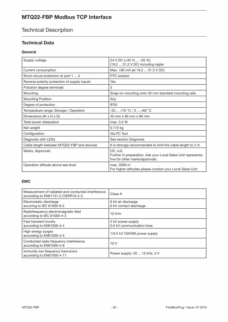
Technical Data
General
Supply voltage 24 V DC (+30 % ... -20 %) (19.2 ... 31.2 V DC) including ripple
Current consumption Max. 180 mA (at 19.2 ... 31.2 V DC)
Short-circuit protection at port 1 ... 4 PTC resistor.
Reverse polarity protection of supply inputs Yes
Pollution degree terminals 3
Mounting Snap-on mounting onto 35 mm standard mounting rails
Mounting Position Any
Degree of protection IP20
Temperature range: Storage / Operation -25 ... +70 °C / 0 ... +60 °C
Dimensions (W x H x D) 45 mm x 90 mm x 96 mm
Total power dissipation max. 3,5 W
Net weight 0.172 kg
Configuration Via PC Tool
Diagnosis with LEDs See section Diagnosis
Cable length between MTQ22-FBP and devices It is strongly recommanded to limit the cable length to 3 m
Marks, Approvals CE, cUL Further in preparation. Ask your Local Sales Unit representa-tive for other marks/approvals.
Operation altitude above sea level max. 2000 m For higher altitudes please contact your Local Sales Unit.
EMC
Measurement of radiated and conducted interference according to EN61131-2 CISPR16-2-3
Class A
Electrostatic discharge accoring to IEC 61000-6-2
8 kV air discharge 6 kV contact discharge
Radiofrequency electromagnetic field according to IEC 61000-4-3
10 V/m
Fast transient bursts according to EN61000-4-4
2 kV power supply 0.5 kV communication lines
High energy surges according to EN61000-4-5
1/0.5 kV CM/DM power supply
Conducted radio frequency interference according to EN61000-4-6
10 V
Immunity low frequency harmonics according to EN61000-4-11
Power supply: 50 ... 12 kHz, 3 V
MTQ22-FBP Modbus TCP Interface
Technical Description
MTQ22-FBP Modbus TCP Interface
Technical Description
- 33 - MTQ22-FBPFieldBusPlug / Issue: 07.2015
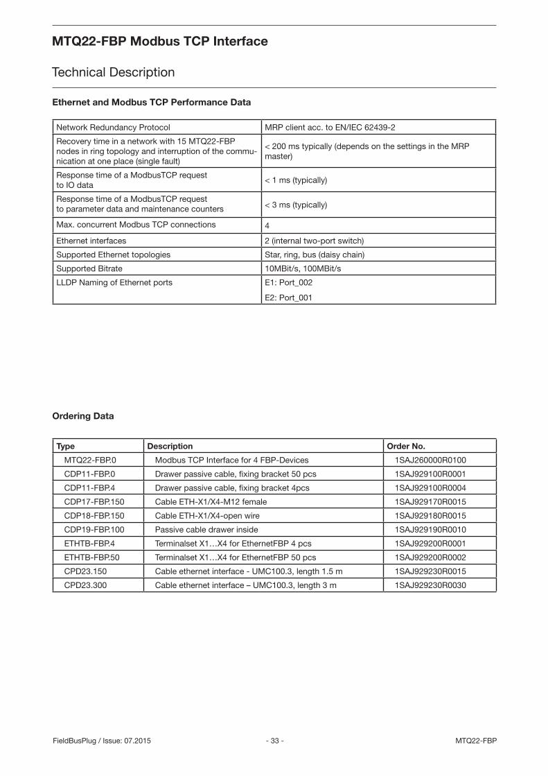
Ordering Data
Type Description Order No.
MTQ22-FBP.0 Modbus TCP Interface for 4 FBP-Devices 1SAJ260000R0100
CDP11-FBP.0 Drawer passive cable, fixing bracket 50 pcs 1SAJ929100R0001
CDP11-FBP.4 Drawer passive cable, fixing bracket 4pcs 1SAJ929100R0004
CDP17-FBP.150 Cable ETH-X1/X4-M12 female 1SAJ929170R0015
CDP18-FBP.150 Cable ETH-X1/X4-open wire 1SAJ929180R0015
CDP19-FBP.100 Passive cable drawer inside 1SAJ929190R0010
ETHTB-FBP.4 Terminalset X1…X4 for EthernetFBP 4 pcs 1SAJ929200R0001
ETHTB-FBP.50 Terminalset X1…X4 for EthernetFBP 50 pcs 1SAJ929200R0002
CPD23.150 Cable ethernet interface - UMC100.3, length 1.5 m 1SAJ929230R0015
CPD23.300 Cable ethernet interface – UMC100.3, length 3 m 1SAJ929230R0030
Ethernet and Modbus TCP Performance Data
Network Redundancy Protocol MRP client acc. to EN/IEC 62439-2
Recovery time in a network with 15 MTQ22-FBP nodes in ring topology and interruption of the commu-nication at one place (single fault)
< 200 ms typically (depends on the settings in the MRP master)
Response time of a ModbusTCP request to IO data
< 1 ms (typically)
Response time of a ModbusTCP request to parameter data and maintenance counters < 3 ms (typically)
Max. concurrent Modbus TCP connections 4
Ethernet interfaces 2 (internal two-port switch)
Supported Ethernet topologies Star, ring, bus (daisy chain)
Supported Bitrate 10MBit/s, 100MBit/s
LLDP Naming of Ethernet ports E1: Port_002
E2: Port_001
MTQ22-FBP Modbus TCP Interface
Technical Description
MTQ22-FBP Modbus TCP Interface
Technical Description
- 34 -MTQ22-FBP FieldBusPlug / Issue: 07.2015
24VDC0V
Port 1
Port 2
Port 3
RDY
TCP
Link
Data
Link
Data
MTQ22
Port 4
X1
X2
X3
X4
X5
X6
E1
E2
1.77"
3.54
"
3.8"45
90
96
mm / inch
2CD
C34
2200
4F00
12
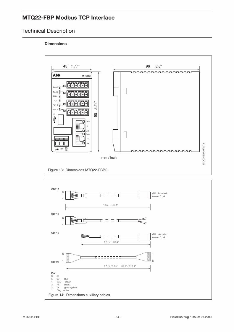
Dimensions
Figure 13: Dimensions MTQ22-FBP.0
Figure 14: Dimensions auxiliary cables
Pin6 nc5 0V blue4 VCC brown3 Rx black2 Tx green/yellow1 Diag white
1.5 m 59.1“
6
1
M12 A-codedfemale 5 pol.
CDP17
6
1
6
1
1
6
CDP18
M12 A-codedfemale 5 pol.
CDP19
CDP23
1.0 m 39.4“
1.5 m / 3.0 m 59.1“ / 118.1“
MTQ22-FBP Modbus TCP Interface
Technical Description
MTQ22-FBP Modbus TCP Interface
Technical Description
- 35 - MTQ22-FBPFieldBusPlug / Issue: 07.2015
Document-No.: 2CDC194003D0202
Detected an Error?Your feedback helps us to constantly improve our products. We are grateful for your comments and suggestions. Please provide us with the following information if you have noticed an issue:
Name
Company / Department
Telephone / Email
Problem Description
• Steps to reproduce the problem
• Version of UMC (Ident number on nameplate and firmware version which is displayed on the UMC100-PAN)
• Version of MTQ (Ident number on nameplate)
• Version of config tool / Windows version (Control->System)
FAX No.: +49 (0) 6221-701-1382

- 36 -
MEMO
MTQ22-FBP FieldBusPlug / Issue: 07.2015
MTQ22-FBP Modbus TCP Interface
Technical Description
MTQ22-FBP Modbus TCP Interface
Technical Description

ABB STOTZ-KONTAKT GmbHP. O. Box 10 16 8069006 Heidelberg, Germany
Phone: +49 (0) 6221 7 01-0Fax: +49 (0) 6221 7 01-240 E-Mail: [email protected] http://www.abb.de/stotzkontakt
Contact
Note:
We reserve the right to make technical changes or
modify the contents of this document without prior
notice. With regard to purchase orders, the agreed
particulars shall prevail. ABB AG does not accept
any responsibility whatsoever for potential errors or
possible lack of information in this document.
We reserve all rights in this document and in the
subject matter and illustrations contained therein.
Any reproduction, disclosure to third parties or
utilization of its contents – in whole or in parts – is
forbidden without prior written consent of ABB AG.
Copyright© 2015 ABB
All rights reserved
2C
DC
194
003
D02
02 R
ev B
07.2
015