Embed Size (px)
Citation preview
i
M–Traverse
User Manual
0001-0122
Revision F

i i
Technical AssistanceIf you have comments or questions concerning the operation of the M–Traverse, a member ofour Technical Support Staff will be happy to assist you. Ask for Technical Support:(763) 424-7800 or (800) 342-4411
Contrex ®
8900 Zachary Lane NorthMaple Grove, Minnesota 55369
Copyright © 1996 Contrex

DANGER
Improper installationor improper operationof this motion control unitcan cause severe injury, death ordamage your system.
Integrate this motion control unitinto your systemwith caution.
Comply with the NationalElectrical Codeand all applicable localand national codes.
i
Table of Contents
Introduction 1-1
Introducing the M–Traverse ........................................................................... 1-3Examples of M–Traverse Applications .......................................................... 1-4
Installation / Setup 2-1
Configuration.................................................................................................. 2-3Mounting ........................................................................................................ 2-7Wiring ............................................................................................................. 2-9
Inputs .................................................................................................. 2-10Outputs ............................................................................................... 2-19Serial Communications ...................................................................... 2-24
Calibration .................................................................................................... 2-27Motor Drive Set Up............................................................................. 2-29Encoder Polarity Check ..................................................................... 2-29M–Traverse Calibration ...................................................................... 2-30
Operation3-1
Keypad Operation .......................................................................................... 3-3Control Parameters ........................................................................................ 3-7
Follower Mode ...................................................................................... 3-8Direct Mode ........................................................................................ 3-29Jog ...................................................................................................... 3-30Tuning................................................................................................. 3-32Output Control .................................................................................... 3-34
M–Traverse Operation ................................................................................. 3-43Follower Mode .................................................................................... 3-44Home Set ........................................................................................... 3-45Home Seek......................................................................................... 3-45Home Return ...................................................................................... 3-50Direct Mode ........................................................................................ 3-51Jog ...................................................................................................... 3-52

ii
Monitor Variables ......................................................................................... 3-53Input Monitoring ................................................................................. 3-54Output Monitoring ............................................................................... 3-56Performance Monitoring ..................................................................... 3-58Status Monitoring ............................................................................... 3-60
Serial Communications ................................................................................ 3-63Using Serial Communications ............................................................ 3-64Communications Software Design ..................................................... 3-66
Troubleshooting 4-1
Diagnostics .................................................................................................... 4-3Troubleshooting ........................................................................................... 4-13EPROM Chip Replacement ......................................................................... 4-19
References 5-1
Glossary ......................................................................................................... 5-3Appendix A: M–Traverse Specifications ..................................................... 5-11Appendix B: Formulas ................................................................................ 5-13Appendix C: Parameter Summary - Numeric Quick Reference ................. 5-14Appendix D: Control Parameter Reference ................................................ 5-36Appendix E: Monitor Variable Reference.................................................... 5-38Appendix F: Fax Cover Sheet .................................................................... 5-39Appendix G: Wiring Diagram Examples ..................................................... 5-40Appendix H: Revision Log .......................................................................... 5-44Service policy ............................................................................................... 5-45Warranty ....................................................................................................... 5-46Index ............................................................................................................ 5-47

iii
List of Illustrations
Figure 1-1 M–Traverse Level Wind Application ........................................ 1-4Figure 1-2 M–Traverse Web Scanning Application .................................... 1-5Figure 2-1 Rear View of M–Traverse ........................................................ 2-3Figure 2-2 Power Board / Isolator Jumper ................................................ 2-4Figure 2-3 Power Board / SW1 Switch ...................................................... 2-5Figure 2-4 M–Traverse Mounting and Cutout Dimensions ....................... 2-6Figure 2-5 M–Traverse General Wiring Schematic ................................... 2-8Figure 2-6 Input Power ............................................................................. 2-10Figure 2-7 Lead frequency ...................................................................... 2-10Figure 2-8 Feedback frequency .............................................................. 2-11Figure 2-9 Home Sync ............................................................................. 2-11Figure 2-10 Setpoint Select A .................................................................... 2-12Figure 2-11 Setpoint Select B .................................................................... 2-12Figure 2-12 Home Set ................................................................................ 2-13Figure 2-13 Home Seek ............................................................................. 2-13Figure 2-14 Home Return ........................................................................... 2-14Figure 2-15 Batch Reset ............................................................................ 2-14Figure 2-16 Run ......................................................................................... 2-15Figure 2-17 Wait ......................................................................................... 2-15Figure 2-18 F-Stop ..................................................................................... 2-16Figure 2-19 Keypad Lockout ..................................................................... 2-16Figure 2-20 Forward Limit .......................................................................... 2-17Figure 2-21 Reverse Limit ......................................................................... 2-17Figure 2-22 Jog Forward/Reverse ............................................................. 2-18Figure 2-23 Jog ......................................................................................... 2-18Figure 2-24 Speed Command Out ............................................................ 2-19Figure 2-25 Discrete Outputs ..................................................................... 2-23Figure 2-26 M-Traverse Multidrop Installation .......................................... 2-24Figure 2-27 M-Traverse Serial Communications Connections .................. 2-25Figure 2-28 Location of M-Traverse Scale and Zero Pot ........................... 2-28Figure 3-1 M–Traverse Front Panel .......................................................... 3-5Figure 3-2 M–Traverse Internal Structure ............................................... 3-58Figure 4-1 Motor Does Not Stop Flowchart ............................................ 4-14
iv
Figure 4-2 Motor Does Not Run Flowchart ............................................. 4-15Figure 4-3 Motor Runs at Wrong Speed Flowchart ................................ 4-16Figure 4-4 Motor Runs Unstable Flowchart ............................................ 4-17Figure 4-5 EPROM Location ................................................................... 4-18Figure G-1 M–Traverse Wiring Connections without Relays .................. 5-40Figure G-2 Relay Run/Stop Wiring Connections .................................... 5-41Figure G-3 Run/Stop for Regen with Armature Contactor ...................... 5-42Figure G-4 Run/Stop for Non-Regen with Armature Contactor .............. 5-43

v
List of Tables
Table 3-1 Basic Keypad Entry ................................................................. 3-4Table 3-2 Default Control Mode Control Parameters .............................. 3-9Table 3-3 Entering Control Mode Control Parameters ............................ 3-9Table 3-4 Default Follower Scaling Control Parameters ....................... 3-11Table 3-5 Entering Follower Scaling Control Parameters ..................... 3-12Table 3-6 Default Setpoint Control Parameters ..................................... 3-13Table 3-7 Entering Setpoint Control Parameters ................................... 3-14Table 3-8 Default Traverse Length Control Parameters ........................ 3-15Table 3-9 Entering Traverse Length Control Parameters ...................... 3-15Table 3-10 Default Accel/Decel Length Control Parameters ................... 3-17Table 3-11 Entering Accel/Decel Length Control Parameters ................. 3-17Table 3-12 Default Dwell Control Parameters ......................................... 3-18Table 3-13 Entering Dwell Control Parameters ...................................... 3-18Table 3-14 Default Control Parameters for Changes .............................. 3-23Table 3-15 Entering Control Parameters for Changes ............................ 3-23Table 3-16 Default Resume Enable Control Parameter .......................... 3-25Table 3-17 Entering Resume Enable Control Parameter ........................ 3-25Table 3-18 Default Polarity Control Parameters ...................................... 3-27Table 3-19 Entering Polarity Control Parameters .................................... 3-27Table 3-20 Default Direct Mode Control Parameters ............................... 3-28Table 3-21 Entering Polarity Control Parameters ................................... 3-28Table 3-22 Default Direct Mode Control Parameters ............................... 3-29Table 3-23 Entering Direct Mode Control Parameters ............................. 3-29Table 3-24 Default Jog Control Parameters ............................................ 3-30Table 3-25 Entering Jog Control Parameters .......................................... 3-30Table 3-26 Default Tuning Control Parameters ....................................... 3-32Table 3-27 Entering Tuning Control Parameters ..................................... 3-33Table 3-28 Default Batch Control Parameters ......................................... 3-35Table 3-29 Entering Batch Control Parameters ....................................... 3-35Table 3-30 Default Alarm Control Parameter ........................................... 3-36Table 3-31 Entering Alarm Control Parameter ......................................... 3-36Table 3-32 Default At-Home Control Parameter ...................................... 3-37Table 3-33 Entering At-Home Control Parameter .................................... 3-37

vi
Table 3-34 Default Control Parameters for Output A ............................... 3-39Table 3-35 Entering Control Parameters for Output A ............................. 3-39Table 3-36 Default Control Parameters for Output B ............................... 3-41Table 3-37 Entering Control Parameters for Output B ............................ 3-41Table 3-38 Parameter Send - Host Transmission..................................... 3-67Table 3-39 Parameter Send - M–Traverse Response ............................. 3-69Table 3-40 Control Command Send - Host Transmission ....................... 3-71Table 3-41 Control Command Send - M–Traverse Response ................. 3-73Table 3-42 Data Inquiry - Host Transmission ........................................... 3-75Table 3-43 Data Inquiry - M–Traverse Response .................................... 3-77Table 3-44 ASCII to Binary ...................................................................... 3-79Table 3-45 Binary Monitor Parameters .................................................... 3-80

1-1
Introduction
Introducing the M–TraverseExamples of M–Traverse Applications
1-2

1-3
INTRODUCING THE M–TRAVERSE
The M–Traverse is a highly accurate, digital, position controller. The M–Traverse'stechnically advanced, internally embedded, control software is specifically designed forthe precise control of reciprocating lead/follower motion applications. Theseapplications are characterized by symmetric forward and reverse follower profiles. TheM–Traverse is often used for level winding, web scanning and fabric lapping, however itcan be used in any operation that requires symmetrical follower profiling against a lead.
The M-Traverse allows you to enter information that is unique to your system'soperation through user friendly Control Parameters. The M–Traverse uses thisinformation to calculate and determine a variety of controls and functions and frees youfrom complex computations. When your system is engaged (Run), the traversingmechanism (Follower) accelerates from the “Home” position to the preset laypitch(Setpoint). Operating at the laypitch, the traverse mechanism can precisely align aproduct on a reel or web then decelerate the traversing mechanism to the end of theTraverse Length before beginning the end Dwell. At the “Dwell,” the M-Traverseassures that the product is properly aligned before returning in the opposite direction.The M–Traverse is remarkably precise - within one encoder line.
The M–Traverse accepts up to four preset pairs of “Setpoint” and “Traverse Length”parameters. These parameters can be engaged with a quick flip of a switch during aproduct change over. The M-Traverse features additional advanced control thatincludes; profile definition that uses engineering unit parameters, dynamic profileredefinition during a run, automatic profile generation, batch counting, unipolar/bipolardrive compatibility and dynamic system monitoring. There are seven discrete outputsfor external control integration, which includes two user specified profile positionoutputs.
Although the M–Traverse has many advanced control capabilities, it is easy to use. Theintegrated keypad and display make access to the control and monitor parameters bothdirect and simple. A “Keypad Lockout” function allows you to restrict access to thecontrol parameters after you have completed the setup process.
The M–Traverse features dedicated short-cut keys for quick access to the “Setpoint,”“Batch Count,” “Tach,” and “Status” parameters. In addition to the integrated userkeypad and display, the M–Traverse has a RS-422 serial communications port throughwhich you can gain computer access to all of the control and monitor parameters.Integrating the M–Traverse's applied intelligence with your system puts precise controland perfect synchronization at your fingertips, quickly, easily and cost effectively.

1-4
EXAMPLES OF M–TRAVERSEAPPLICATIONS
The Level W ind is one of the M–Traverse's principle applications. The Level Windapplication uses the Lay Adjusted option in the Follower mode of operation. In a LevelWind application, the M–Traverse locates the start or “Home” position and acceleratesthe traversing mechanism (Follower) to the preset laypitch (Setpoint). The traversingmechanism feeds a web product such as a wire, fiber optic cable or tape, onto therotating reel (Lead) at this laypitch then decelerates the traversing mechanism to theend of the Traverse Length. At the “Dwell,” the M-Traverse assures that the webmaterial is properly aligned on the reel before returning in the opposite direction.Figure 1-1 illustrates a typical Level Wind application.
DIRECTIONOF WIND
FOLLOWER LEAD
CONTREX
FEEDBACK FREQUENCY
HOME SYNC
LEAD FREQUENCY
M-TRAVERSE
StatusBatchCount
7 8 9
4 5 6
1 2 3
0
Clear Enter
Cut Length Position
Alt
M–Traverse
Figure 1-1 M–Traverse Level Wind Application

1-5
Web Scanning is another common M–Traverse application. The Web Scanningapplication frequently uses the Standard option in the Follower mode of operation,however, there are applications for which Web Scanning may use the Lay Adjustedoption in the Follower mode of operation. The M–Traverse locates the start or “Home”position and accelerates the traversing mechanism (Follower) to the preset laypitch(Setpoint). The traversing mechanism applies a secondary product, such as glue orreinforcing fiber, onto the moving web. Then the M–Traverse decelerates the traversingmechanism to zero speed at the end of the “Traverse Length”. At the “Dwell” (which isusually set at zero) the traversing mechanism reverses its direction and returns with asymmetric reverse profile. Using zero or very low “Accel / Decel” and “Dwell”parameters creates a zigzag pattern. Figure 1-2 illustrates a typical Web Scanningapplication.
Figure 1-2 M–Traverse Web Scanning Application
CONTREX
FEEDBACK FREQUENCY
HOME SYNC
LEAD FREQUENCY
LINE FLOW
FOLLOWER
LEAD
M-TRAVERSE
StatusBatchCount
7 8 9
4 5 6
1 2 3
0
Clear Enter
Cut Length Position
Alt
M–Traverse

1-6
—NOTES—

2 - 1
Installation / Setup
ConfigurationMountingWiring
InputsOutputsSerial Communications
CalibrationMotor Drive SetupM-Traverse Calibration

2 - 2

2 - 3
CONFIGURATIONThis section will show you how to re-configure the M-Traverse for electricalcompatibility. Complete these procedures prior to installation. These procedures donot require power to complete.
The two areas that are involved in re-configuring the M-Traverse are the IsolatorVoltage jumper and the Power Voltage switch. Do not re-configure the M-Traverse'sFrequency Input. Use the default Quadrature position.
To re-configure the Isolator Voltage jumper and the Power Voltage switch, remove theback plate, then carefully remove the Power Board. Figure 2-1 illustrates the locationof the boards.
Figure 2-1 Rear View of M-Traverse
Power Board CPU Board
2 - 4
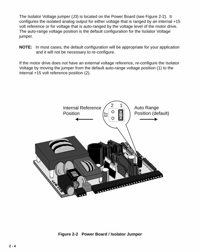
The Isolator Voltage jumper (J3) is located on the Power Board (see Figure 2-2). Itconfigures the isolated analog output for either voltage that is ranged by an internal +15volt reference or for voltage that is auto-ranged by the voltage level of the motor drive.The auto-range voltage position is the default configuration for the Isolator Voltagejumper.
NOTE: In most cases, the default configuration will be appropriate for your applicationand it will not be necessary to re-configure.
If the motor drive does not have an external voltage reference, re-configure the IsolatorVoltage by moving the jumper from the default auto-range voltage position (1) to theinternal +15 volt reference position (2).
Figure 2-2 Power Board / Isolator Jumper
115
Auto Range Position (default)
Internal ReferencePosition
2 1
J3

2 - 5
The Power Voltage switch (SW1) is located on the Power Board (see Figure 2-3). Thedefault configuration for the Power Voltage switch is 115 VAC.
NOTE: In most cases, the default configuration will be appropriate for your applicationand it will not be necessary to re-configure.
To re-configure for 230V, move the switch from the 115V position (left) to the 230Vposition (right).
Figure 2-3 Power Board / SW1 Switch
115
115V 230V115V
(default)

2 - 6
��
��
M-TRAVERSE
3.6"
7.2"
7.5"
5.7"
3.9"
���
DOOR PANEL(3.65" .03" CUTOUT (
CUTOUT7.25" .03" ( )
Contrex
Contrex
Set
Figure 2-4 M–Traverse Mounting and Cutout Dimensions
2 - 7
MOUNTING
This section contains instructions for mounting the M–Traverse in the door panel of aNEMA Industrial Electrical enclosure. The M–Traverse is packaged in a compact 1/2DIN Vertical Instrument Enclosure that mounts easily in the door of your IndustrialElectrical Enclosure.
To mount the M–Traverse:
1) The NEMA Industrial Electrical Enclosure that will house the M–Traverse must conform to the following environmental conditions:
Temperature: 0 - 55 degrees C (Internal NEMA enclosure temperature)
Humidity: 0 - 90% RH non-condensing
2) The dimensions for the door panel cutout are 3.65"+ .03" X 7.25 +.03"(see figure 2-4). Allow two inches of clearance on all sides of thecutout for mounting clamp attachments, wire routing and heatconvection.
3) Insert the M–Traverse through the door panel cutout until the gasketand bezel are flush with the door panel (see figure 2-4).
4) The mounting clamps can be inserted in the holes that are locatedeither on the top and bottom or on the sides of the M–Traverse.Tighten the mounting screws until the M–Traverse is mounted securelyin the NEMA Electrical Enclosure. Do not overtighten.

2 - 8
* P
ower
for
enco
der
and
prox
sw
itche
s m
ay b
e su
pplie
d by
J3,
pin
s 1
or 2
.
Tot
al +
5 V
DC
cur
rent
sho
uld
not e
xcee
d 25
0 m
AT
otal
+12
VD
C c
urre
nt s
houl
d no
t exc
eed
200
mA
J1+
12 V
OU
T50 M
A M
AX
+ TX
D– + R
XD
–
CO
M +V
SIG
SIO
CO
M
DR
IVE
EN
AB
LE
BA
TC
HD
ON
E
ALA
RM
PR
OF
ILE
D
IR
AT
HO
ME
OU
TP
UT
A OU
TP
UT
B
+ E X T D C S U P P L Y –
R R R R
D R I V E
SERIAL COMMUNICATIONSRS 485
L E A D F E E D B A C K
J
3
C
HA
C
OM
C
HB
S
HIE
LD
C
HA
C
OM
C
HB
C
OM
HO
ME
SY
NC
ST
PT
SE
L A
(
C)
C
OM
ST
PT
SE
L B
(
C)
HO
ME
SE
TJ3
(
C)
J4 C
OM
H
OM
ES
EE
K(C
)
H
OM
E
RE
TU
RN
(C)
C
OM
BA
TC
HR
ES
ET
(C)
RU
N(C
)
C
OM
WA
IT (
O)
F–S
TO
P(O
)
C
OM
K
EY
PA
D L
OC
KO
UT
(C)
F
OR
WA
RD
L
IMIT
(C)
C
OM
R
EV
ER
SE
L
IMIT
(C)
F
WD
(O)
J
OG
R
EV
(C)
C
OM
JO
G(C
)
S
HIE
LD
J4
+5 V
OU
T
500 M
A M
AX
+
12 V
OU
T
150 M
A M
AX
INP
UT
VO
LT
AG
E –
11
5/2
30
VA
CIN
PU
T C
UR
RE
NT
– 0
.25
AM
PIN
PU
T F
RE
QU
EN
CY
– 5
0/6
0 H
Z
J2
US
E C
OP
PE
R W
IRE
ON
LY
.S
EL
EC
T W
IRE
SIZ
E A
CC
OR
DIN
G T
O A
MP
AC
ITY
FO
R 6
0/7
5 C
WIR
ET
IGH
TE
N T
ER
MIN
AL
S T
O 5
IN
/LB
120 V
FUSE
FUSE
R R R
1 2 3 4 5 6 7 8 9 10 11 12 13 14 15 16 17 18 19 20 1 2 31 2 3
+ 1
2VD
C A
UX
OU
T
R R R R R R
DR
IVE
+ V
DC
SIG
NA
L
ISO
CO
MM
ON
DR
IVE
EN
AB
LE
BA
TC
H D
ON
E
ALA
RM
PR
OF
ILE
DIR
AT
-HO
ME
OU
TP
UT
A
OU
TP
UT
BR
EX
T
DC
SU
PL+ –
TX
D +
TX
D –
RX
D +
RX
D –
CO
MM
ON
RS
422
SE
RIA
LC
OM
M CH
AS
SIS
GN
D
NE
UT
RA
L / L
2 L1
AC
PO
WE
R
J1 J2
50 V Max
1 2 3 4 5 6 7 8 9 10 11 12 13 14 15 16 17 181 2 3 4 5 6 7 8 9 10 11 12 13 14 15 16
+ 5
VD
C A
UX
OU
T
+12
VD
C A
UX
OU
T
J3
CH
A
CO
M
CH
B S
HLD
CH
A
CO
M
CH
B
LEA
D
*
QU
AD
EN
CO
DE
R
FE
ED
BA
CK*
QU
AD
EN
CO
DE
R HO
ME
*S
YN
C
SE
TP
OIN
TS
ELE
CT
A
SE
TP
OIN
TS
ELE
CT
B
HO
ME
SE
T
HO
ME
SE
EK
HO
ME
RE
TU
RN
BA
TC
H R
ES
ET
RU
N
WA
IT
F–S
TO
P
KE
YP
AD
LO
CK
OU
T
FO
RW
AR
D L
IMIT
RE
VE
RS
E L
IMIT
JOG
FO
RW
AR
D/R
EV
ER
SE
JOG
SH
IELD
J4
CH
AS
SIS
GN
D
NE
UT
/L2
L1
Fig
ure
2-5
M-T
rave
rse
Gen
eral
Wiri
ng S
chem
atic

2 - 9
WIRING
This section contains the input, output and serial communications wiring information forthe M–Traverse. Please read this section prior to wiring the M–Traverse to ensure thatyou make the appropriate wiring decisions.
NOTE: The installation of this motor control must conform to area and local electricalcodes. See The National Electrical Code (NEC,) Article 430 published by theNational Fire Protection Association, or The Canadian Electrical Code (CEC).Use local codes as applicable.
Use a minimum wire gauge of 18 AWG.
Use shielded cable to minimize equipment malfunctions from electrical noiseand terminate the shields at the receiving end only.
Keep the AC power wiring (J2) physically separated from all other wiring onthe M–Traverse. Failure to do so could result in additional electrical noise andcause the M–Traverse to malfunction.
Inductive coils on relay, contactors, solenoids that are on the same AC powerline or housed in the same enclosure should be suppressed with an RCnetwork across the coil. For the best results, use resistance (r) values of 50ohms and capacitance (c) values of 0.1 microfarads.
Install an AC line filter or isolation transformer to reduce excessive EMI noise,such as line notches or spikes, on the AC power line.
DANGER
Hazardous voltages.Can cause severe injury, death ordamage to the equipment.The M–Traverse should only beinstalled by a qualifiedelectrician.

2 - 10
INPUTS
NOTE: The installation of this motor control must conform to area and local electricalcodes. See The National Electrical Code (NEC,) Article 430 published by theNational Fire Protection Association, or The Canadian Electrical Code (CEC).Use local codes as applicable.
Input Power (J2 pins 1, 2, 3)
The M–Traverse operates on either a115 VAC or 230 VAC (-10% + 15%,0.25 Amps., 50/60 Hz). Use theseparate 3 pin connector (J2) for thepower connection.
Lead Frequency (J3 pins3,4,5,6)
The Lead Frequency is a pulse traininput that the M-Traverse uses todetermine the Lead motor's speedand position. The Lead Frequencysignal must be quadrature. Forsignal level specifications, refer toReferences: Appendix A,M–Traverse Specifications.
Figure 2-6 Input Power
Figure 2-7 Lead Frequency
LeadQuadEncoder
3
4
5
6
J3
CHA
COM
CHB
Shield
Chassis Gnd
Neutral / L2
L1
1
2
3
J2

2 - 11
Feedback Frequency(J3 pins 6,7,8,9)
The Feedback Frequency is a pulsetrain input that the M-Traverse uses todetermine the Follower motor's speedand position. The FeedbackFrequency signal must be quadrature.For signal level specifications, refer toReferences: Appendix A, M–TraverseSpecifications.
Home Sync (J3 pins 6,11,12)
The Home Sync input identifies thelocation of “Home” for the Home Seekoperation. This input is operated byeither a proximity switch or an opticalsensor switch (NPN output).
Figure 2-9 Home Sync
Figure 2-8 Feedback Frequency
6
7
8
9
J3
FeedbackQuadEncoder
Shield
CHA
COM
CHB
Shield
Common
Home Sync
6
11
12
J3
WARNING
If the Feedback Frequency is lost,the M-Traverse will command a !00% Speed Outand the motor will run at 100% of the calibrated range.This can cause severe injury, death orit can damage your equipment.

2 - 12
Setpoint Select A(J3 pins 13,14)
The Setpoint Select A and B inputsare used in conjunction with eachother to select one of fourM–Traverse setpoints and traverselengths. The chart below displaysthese four setpoints.
Setpoint Select B(J3 pins 14,15)
The Setpoint Select A and B inputsare used in conjunction with eachother to select one of fourM–Traverse setpoints and traverselengths. The chart below displaysthese four setpoints.
Figure 2-10 Setpoint Select A
Figure 2-11 Setpoint Select B
Setpoint Select B
14
15
J3
Setpoint Select A
13
14
J3
Setpoint Select AOpen
Setpoint Select AClosed
Setpoint Select BOpen
Setpoint Select BOpen
Setpoint Select BClosed
Setpoint 1Traverse Length 1
Setpoint 2Traverse Length 2
Setpoint 3Traverse Length 3
Setpoint 4Traverse Length 4

2 - 13
Figure 2-12 Home Set
Home Set (J3 pins 14,16)
Home Set is a momentary input thatis edge triggered. When Home Set isclosed, it sets the current position asthe new “Home” position.
Home Seek (J4 pins 1,2)
Home Seek is a momentary input thatis edge triggered. When Home Seekis closed, the Follower makes asustained move at Jog speed, until itreaches the “Home” sensor. As amomentary input, Home Seek isinternally latched and does not needto be maintained by an operatordevice.
Figure 2-13 Home Seek
Home Set
14
16
J3
1
2
J4
Home Seek

2 - 14
Home Return (J4 pins 3,4)
Home Return is a momentary inputthat is edge triggered. When HomeReturn is closed, the follower returnsto the established “Home” position.As a momentary input, Home Returnis internally latched and does notneed to be maintained by an operatordevice.
Batch Reset (J4 pins 4,5)
In a closed position, the Batch Resetinput resets the batch count to zero.
Figure 2-14 Home Return
Figure 2-15 Batch Reset
4
5
J4
Batch Reset
Home Return
3
4
J4

2 - 15
Run (J4 pins 6,7)
When the Run input is momentarilyclosed, the M–Traverse enters Run.As a momentary input, Run isinternally latched and does not needto be maintained by an operatordevice.
NOTE: Close the F–Stop input priorto entering Run.
Wait (J4 pins 7,8)
When the M–Traverse is in Run, itchecks the Wait input before itproceeds with the next profile movein either the forward or reversedirection. If the Wait input is closed,it will pause at the end of the profileuntil the wait input opens.
Figure 2-16 Run
Figure 2-17 Wait
RUN
6
7
J4
Wait
8
7
J4

2 - 16
F-Stop (J4 pins 9,10)
F-Stop is a momentary input. Whenit is opened, the Follower stopsimmediately (zero RPM) and ignoresthe specified deceleration rate. As amomentary input, F-STOP isinternally latched and does not needto be maintained by an operatordevice.
Keypad Lockout (J4 pins 10,11)
When the Keypad Lockout is closed,it selectively disables the frontkeypad so that setpoint and othercontrol parameters can not bechanged. All of the monitoringfunctions remain enabled.
Figure 2-18 F-Stop
Figure 2-19 Keypad Lockout
F-STOP
9
10
J4
KeypadLockout
10
11
J4

2 - 17
Figure 2-20 Forward Limit
Figure 2-21 Reverse Limit
ForwardLimit
12
13
J4
13
14
J4
ReverseLimit
Forward Limit (J4 pins 12,13)
When Forward Limit is closed (edge-triggered), it prevents the followerfrom moving forward. When theM–Traverse detects a Forward Limit,it will go to F–Stop from Forward Jog,Home Seek or Run, if CP-37 is set to“1”. If CP-37 is set to “2”, then theM-Traverse will begin a reverseprofile when it detects a ForwardLimit. To deactivate Forward limit,use any reverse command (e.g.,Reverse Jog).
Reverse Limit (J4 pins 13,14)
When Reverse Limit is closed (edge-triggered), it prevents the followerfrom moving in reverse. When theM–Traverse detects a Reverse Limit,it will go to F–Stop from either Run,Reverse Jog or Home Seek (anyreverse move). To deactivateReverse limit, use any forwardcommand (e.g., Forward Jog).

2 - 18
Jog Forward/Reverse (J4 pins15,16)
The Jog Forward/Reverse inputcontrols the direction of the SpeedCommand Output while it is in Jog.Jog is in the forward direction whenthe input is open. Jog is in thereverse direction when the input isclosed.
Jog (J4 pins 16, 17)
Jog is a maintained input. When theJog input is closed, the M–Traversesends a Speed Command Out signalto the drive at the selected jog speed.As a maintained input, Jog is onlyactive when the operator device isclosed.
NOTE: Close the F–Stop input andopen the Run input, prior toentering Jog.
Figure 2-22 Jog Forward/Reverse
Figure 2-23 Jog
Jog Forward / Reverse
15
16
J4
17
16
J4
Jog

2 - 19
OUTPUTS
NOTE: The installation of this motor control must conform to area and local electricalcodes. See The National Electrical Code (NEC,) Article 430 published by theNational Fire Protection Association, or The Canadian Electrical Code (CEC).Use local codes as applicable.
Speed Command Out (J1 pins 8, 9,10,11)
Speed Command Out is an isolatedanalog output signal that is sent tothe motor drive to control the speedof the motor. Wire the SpeedCommand Out (J1 pin 9) into theSpeed Signal Input of the drive. Ifthe motor drive has a potentiometerspeed control, remove thepotentiometer connections, then wirethe Speed Command Output to thepotentiometer wiper input and wirethe Voltage Reference and IsolatedCommon to the other twopotentiometer input connections. TheM–Traverse's isolated commonshould always be connected to thedrive common.
*
MOTOR DRIVE
8
9
10
11
J1
SIGNAL INPUTSpeed Command Out
Isolated CommonDRIVE COMMON
Voltage Reference
Shield
± V (15V Max)
Figure 2-24 Speed Command Out
Drive Enable (J1 pin 13)
The Drive Enable output is activated (driven low) when the M–Traverse is signaling aspeed command to the motor drive. The Drive Enable output is driven high (relaydeactivated) after Power Up and during F–Stop. Refer to Figure 2-25.
NOTE: This is an open-collector relay driver. For specification details, see Refer-ences: Appendix A, M–Traverse Specifications. Use an external DC powersupply to power the relays. Free-wheeling diodes are incorporated internallyin the M–Traverse and do not need to be added externally.

2 - 20
Batch Done (J1 pin 14)
The Batch Done output is relay activated (driven low ) when the Batch count iscompleted. Refer to Figure 2-25.
NOTE: This is an open-collector relay driver. For specification details, see Refer-ences: Appendix A , M–Traverse Specifications. Use an external DC powersupply to power the relays. Free-wheeling diodes are incorporated internallyin the M–Traverse and do not need to be added externally.
Alarm (J1 pin 15)
The Alarm output is relay activated (driven low) if the system's speed is above thespeed alarm setting that has been entered in the High Speed Alarm (CP-23) parameter.Refer to Figure 2-25.
NOTE: This is an open-collector relay driver. For specification details, see Refer-ences: Appendix A , M–Traverse Specifications. Use an external DC powersupply to power the relays. Free-wheeling diodes are incorporated internallyin the M–Traverse and do not need to be added externally.
Profile Direction (J1 pin 16)
The Profile Direction output indicates the commanded direction of the profile.This output is relay deactivated (driven high) when the profile is commanded to moveforward. This output is relay activated (driven low) when the profile is commanded tomove in reverse. Refer to Figure 2-25.
NOTE: This is an open-collector relay driver. For specification details, see Refer-ences: Appendix A, M–Traverse Specifications. Use an external DC powersupply to power the relays. Free-wheeling diodes are incorporated internallyin the M–Traverse and do not need to be added externally.

2 - 21
At-Home (J1 pin 17)
In order for this output to function, “Home” must have already been determined (usingHome Set or Home Seek). Once ”Home” has been determined, this output is relayactivated (driven low) when the traverse Follower Position is within the At-Home Bandspecified in CP-30. Refer to Figure 2-25.
NOTE: This is an open-collector relay driver. For specification details, see Refer-ences: Appendix A , M–Traverse Specifications. Use an external DC powersupply to power the relays. Free-wheeling diodes are incorporated internallyin the M–Traverse and do not need to be added externally.
Output A (J1 pin 18)
Output A can be set to activate at different segments of the forward and reverseprofiles. The parameter values set in CP-90, CP-91 and CP-92 determine the profilesegment and direction of activation, as well as the polarity (high or low). Refer toFigure 2-25.
NOTE: This is an open-collector relay driver. For specification details, see Refer-ences: Appendix A , M–Traverse Specifications. Use an external DC powersupply to power the relays. Free-wheeling diodes are incorporated internallyin the M–Traverse and do not need to be added externally.
Output B (J1 pin 19)
Output B can be set to activate at different segments of the forward and reverseprofiles. The parameter values set in CP-93, CP-94 and CP-95 determine the profilesegment and direction of activation, as well as the polarity (high or low). Refer toFigure 2-25.
NOTE: This is an open-collector relay driver. For specification details, see Refer-ences: Appendix A, M–Traverse Specifications. Use an external DC powersupply to power the relays. Free-wheeling diodes are incorporated internallyin the M–Traverse and do not need to be added externally.

2 - 22
Auxiliary DC Power (J3 pins 1, 2)
The 5 volt output (J3 pin 1) is a DC regulated output that can be used to powerencoders or other auxiliary equipment that is used in conjunction with the M–Traverse.The 12 volt output (J3 pin 2) is a DC regulated output that can be used to power theproximity sensors or other auxiliary equipment that is used in conjunction with the M–Traverse. Refer to Figure 2-25.
WARNING
Do not exceedthe maximum current output of250 mA for +5 VDC and200 mA for +12 VDC.
Exceeding the maximumcurrent outputcan damage the M–Traverse.

2 - 23
Figure 2-25 Discrete Outputs
12
13
14
15
16
17
18
19
20
J1
EXTERNALDCPOWERSUPPLY
(50V Max)
R
Diode Protect
Drive Enable
Batch Done
Alarm
Profile Dir
At-Home
Output A
Output B
Common
+
–
R
R
R
R
R
R

2 - 24
SERIAL COMMUNICATIONS
NOTE: The installation of this motor control must conform to area and local electricalcodes. See The National Electrical Code (NEC,) Article 430 published by theNational Fire Protection Association, or The Canadian Electrical Code (CEC).Use local codes as applicable.
The Serial Communications interface on the M–Traverse complies with EIA StandardRS–422 for balanced line transmissions. This interface allows the host computer toperform remote computer parameter entry, status or performance monitoring, andremote control of the M–Traverse. See Operations: Serial Communications forinformation on using Serial Communications.
Figures 2-26 and 2-27 illustrate a multidrop installation of the Serial Communicationslink and Serial Communications connections.
M-TRAVERSEM-TRAVERSE
M-TRAVERSE
M-TRAVERSEM-TRAVERSE
M-TRAVERSE
RS-232 to RS-422Converter
Figure 2-26 M-Traverse Multidrop Installation
2 - 25
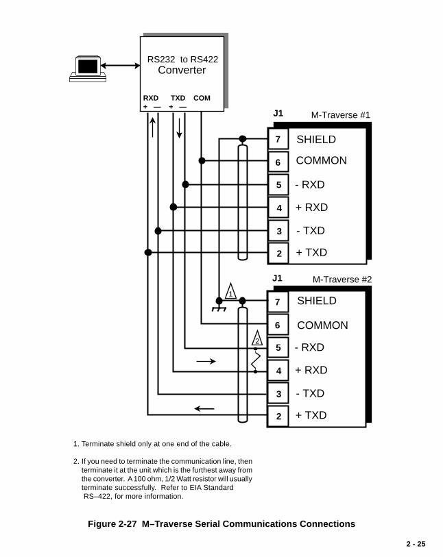
1. Terminate shield only at one end of the cable.
2. If you need to terminate the communication line, thenterminate it at the unit which is the furthest away fromthe converter. A 100 ohm, 1/2 Watt resistor will usuallyterminate successfully. Refer to EIA Standard RS–422, for more information.
RS232 to RS422Converter
2
1
M-Traverse #1
M-Traverse #2
7
6
5
4
3
2
- RXD
+ RXD
- TXD
+ TXD
7
6
5
4
3
2
- RXD
+ RXD
- TXD
+ TXD
J1
J1
SHIELD
SHIELD
COMMON
COMMON
RXD TXD COM+ — + —
Figure 2-27 M–Traverse Serial Communications Connections

2 - 26

2 - 27
CALIBRATION
Calibration matches the analog output of the M–Traverse with the analog input of themotor drive. Calibration is accomplished in two steps. The first step is to set up themotor drive. The second step is to calibrate the M–Traverse to the motor drive so thatthe speed is adjusted to the maximum operating speed. The M–Traverse must beproperly installed prior to calibration. Refer to Installation/Setup; Mounting andInstallation/Setup; Wiring.
Hazardous voltages.
Can cause severeinjury, death ordamageto the equipment.
Make adjustments with caution.
DANGER
2 - 28
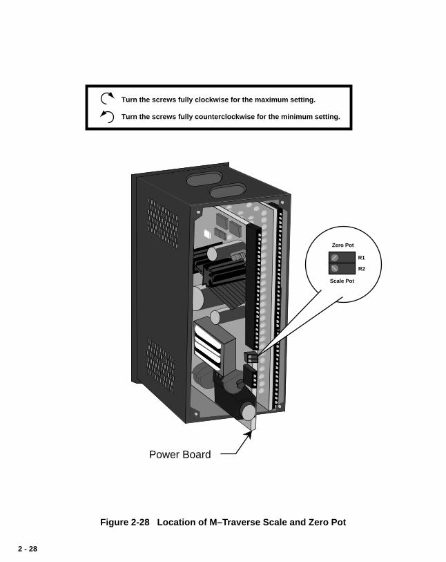
Figure 2-28 Location of M–Traverse Scale and Zero Pot
Power Board
Turn the screws fully clockwise for the maximum setting.
Turn the screws fully counterclockwise for the minimum setting.
Zero Pot
Scale Pot
R1
R2
2 - 29
MOTOR DRIVE SET UP
1) Put the M–Traverse in “F–Stop” by opening the F–Stop input (J4 pins 9and 10). Refer to Installation/Setup: Wiring, F–Stop.
2) Set the drive's Acceleration and Deceleration potentiometers to theirfastest rates (minimum ramp time). The goal is to make the drive asresponsive as possible, which allows the M–Traverse to control thespeed changes.
3) If the drive has a Zero Speed Potentiometer, adjust it to eliminate anymotor creep. If the drive does not have a zero speed pot, then adjustthe zero speed pot on the M–Traverse to eliminate any motor creep.Figure 2-28 shows the location of the M–Traverse zero speed pot.
4) If the drive has an IR Compensation Potentiometer, set it at minimum.
5) Each motor drive has settings that are unique to its particular model.Adjust any remaining drive settings according to the manufacture'srecommendations.
ENCODER POLARITY CHECK
1) Observe MV-41 while you rotate the lead encoder in the direction that is“forward” during normal operation. Switch the lead encoder lines on J3pins 3 and 5 if MV-41 is negative.
2) Observe MV-42 while you rotate the Follower encoder in the directionthat is “forward” during normal operation. Switch the follower encoderlines on J3 pins 7 and 9 if MV-42 is negative.
2 - 30
M–TRAVERSE CALIBRA TION
1) Make sure that the M–Traverse is still in “F–Stop”. If it is not, put theM–Traverse in “F–Stop” by opening the F–Stop Logic input (J4 pins 9and 10). Refer to Installation/Setup: Wiring, F–Stop.
2) Enter the resolution (PPRs) of the feedback sensor in the PPR Follower(CP-18) parameter by entering the following on the keypad:
Press “Code Select”Enter “18”Press “Enter”Enter the Pulses Per Revolution (PPR) of the feedback sensorPress “Enter”
The Tach is now scaled for feedback RPMs.
3) If the M–Traverse is using the drive voltage for reference (J1 pin 8),then set the drive's max speed potentiometer to its minimum setting. Ifthe M–Traverse is using its internal voltage for reference (noconnection to J1 pin 8) then set the drive's max speed potentiometer toits maximum setting and set the M–Traverse's scale pot to its minimumsetting (fully counterclockwise). Figure 2-28 shows the location of theM–Traverse scale pot.
4) The M-Traverse is defaulted for use with bi-directional drives that usebipolar (positive and negative) voltage commands to indicate thedirection. If you are using a single quadrant (direction) drive, thenchange CP-29 to unipolar operation, as follows:
Press “Code Select”Enter “29”Press “Enter”Enter “1”Press “Enter”
5) Enable the M–Traverse's direct control mode by entering the followingon the keypad:
Press “Code Select”Enter “14”Press “Enter”Enter “2”Press “Enter”

2 - 31
6) Put the M–Traverse into RUN by shorting the F–STOP input (J4 pins 9and 10) and the RUN input (J4 pins 6 and 7). Although the motor isnow in RUN, it will have zero speed until you adjust the Direct AnalogCommand (CP-62).
7) Gradually set the M–Traverse's Direct Analog Command to 90% (3686)by entering the following on the keypad:
Press “Setpoint”Enter “400”Press “Enter”Enter “800”Press “Enter”
Continue to gradually increase these increments by 400 until you reach“3686”. Since there are no acceleration/deceleration ramps in Directmode, a sudden increase to “3686” could cause damage in somesystems. If the Follower is not moving in a forward direction, thenrewire the drive/motor leads for forward operation.
Note: A value of –3686 will change the direction of the motor.
8) Turn either the motor drive's max speed or the M–Traverse's scalepotentiometer clockwise until the drive motor's RPMs are at themaximum operating speed at which you want the system to operate.Check the speed (RPMs) by pressing the Tach” key. “Tach” shoulddisplay the RPM speed that you enter in CP-19.
9) Put the Direct Analog Command back to 0% by entering the followingon the keypad:
Press “Setpoint”Enter “0”Press “Enter”
10) Disable the M–Traverse's direct mode by entering the following on thekeypad:
Press “Code Select”Enter “14”Press “Enter”Enter “1”Press “Enter”
11) Put the M–Traverse in “F–Stop” by opening the F–Stop input (J4 pins 9and 10). Refer to Installation/Setup: Wiring, F–Stop.

2 - 32
—NOTES—
3 - 1
Operation
Keypad OperationControl Parameters (CP)
Follower Mode
Direct Mode
Jog
Tuning
Output Control
M-Traverse OperationFollower Mode
Home Set
Home Seek
Home Return
Direct Mode
Jog
Monitor Variables (MV)Input Monitoring
Output Monitoring
Performance Monitoring
Status Monitoring
Serial CommunicationsUsing Serial Communications
Communications Software Design

3 - 2

3 - 3
KEYPAD OPERATION
The front panel of the M–Traverse is an easy to use keypad that gives you directaccess to the Parameters (Control Parameters and Monitor Variables) by entering theParameter Code. You can also use the keypad to change the value of a ControlParameter. The keypad has keys for Code Select, Enter and Clear. It also hasnumeric keys and four dedicated keys: Setpoint, Tach, Status and Batch Count. TheLED display is the above the keys. Refer to figure 3-1 for the location of the keys andLED display on the keypad. Table 3-1 demonstrates basic keypad entry.
The keypad functions as follows:
Code Select Use the “Code Select” key prior to entering a Parameter Codefor either a Control Parameter (CP) or Monitor Variable (MV).
Numeric Use the numeric keys to enter a Parameter Code for either aControl Parameter (CP) or a Monitor Variable (MV) or to entera value for a Control Parameter. Use the “Clear” key to deleteyour entry. Use the “Enter” key after each entry, to enter it inthe M-Traverse.
—/Alt Use the “—/Alt” key to enter a negative value. In MVs 43, 44,80, 81 and 84, the “—/Alt” key toggles between four lower andfour higher digits because some numbers exceed the six digitdisplay panel limit.
. Use the decimal key for values with a decimal point.
Clear The “Clear” key will delete the entry, if you have not used the“Enter” key.
Tach The “Tach” key is a dedicated or shortcut key. You can accessthe tach Parameters directly, rather than manually entering theParameter Code (MV-40).
Setpoint The “Setpoint” Key is a dedicated or shortcut key. You candirectly access the active setpoint in the Follower mode (eitherCP-01, CP-03, CP-05 or CP-07) or the active setpoint in theDirect mode (CP-62).

3 - 4
Batch Count Key The “Batch Count” Key is a dedicated or shortcut key. You candirectly access the Batch Count parameter (MV-89).
Status Key The “Status” Key is a dedicated or shortcut key. You candirectly access the Alarm Status parameter (MV-51).
Lower LED Display The two-digit Parameter Code is displayed on the Lower LEDDisplay.
Upper LED Display The Parameter Code's value is displayed on the Upper LEDdisplay. This value can be up to six digits.
Discrete LED Display There are five discrete LED display lights. When a specificlight is “on”, it indicates the following condition:
Run .................. The M-Traverse is in Follower mode and is executinga profile.
Wait ................. The Wait input (J4 pin 8 ) is active.Drive Enable .... The Drive Enable output (J1 pin 13) is active.At-Home .......... The Follower position is within the At-Home band of
the Home position.Alarm ............... There is an active alarm condition.
To Enter a Parameter Code:
To Enter a Parameter Value:(For Control Parameters only - MonitorVariables can not be changedmanually)
To Use the Tach Key:
To Use the Status Key:
To Use the Setpoint Key:
To Use the Batch Count Key:
Press “Code Select”.Enter a Parameter Code (For a Control Parameter or Monitor Variable).Press “Enter” (within 15 seconds).The Parameter Code and its current value are displayed on the LED displays.
Follow the steps to enter a Parameter Code.Enter a new value (Use the numeric keys) .Press “Enter” (within 15 seconds).
Press “Tach”.The scaled Tach - Velocity is displayed (MV-40).
Press “Status”.The code for the alarm status is displayed (MV-51).
Press “Setpoint”.The value of the active setpoint is displayed, in engineering units. (CP-01,CP-03, CP-05, CP-07 or CP-62).
Press “Batch Count” .The number of complete batch counts is displayed (MV-89).
Table 3-1 Basic Keypad Entry

3 - 5
StatusBatchCount
7 8 9
4 5 6
1 2 3
0
Clear Enter
SetPoint Tach
Alt
Run
CodeSelect
WaitDrive EnblAt-HomeAlarm
UpperLEDDisplay
Code Select Key
NumericKeys
ClearKey
EnterKey
BatchCountKey
SetpointKey Tach
Key
StatusKey
DiscreteLED IndicatorDisplay
ParameterCode (2 digits)
Parameter Value(up to 6 digits)
LowerLEDDisplay
DecimalKey—/Alt
Key
CONTREX
Figure 3-1 The M–Traverse Front Panel

3 - 6

3 - 7
CONTROL PARAMETERS
Parameters are divided into two classifications; Control Parameters (CP) and MonitorVariable (MV). The numbered code that represents the parameter is the ParameterCode. The operational data is the parameter's value.
Control Parameter 14 = 1Parameters =
Monitor Variable 40 = 200
Parameter Code Parameter Value
This section is about Control Parameters. Monitor Variables are explained inOperation: Monitor Parameters.
The M–Traverse comes factory pre-loaded with a complete set of default ControlParameters values. The majority of these default settings are suitable for mostapplications and do not require modification.
Control Parameters allow you to enter data that is unique to your system (e.g., encoderresolution, Lead to Follower ratios) and modify the M–Traverse for your specific needs(e.g., maximum RPM, setpoints, acceleration/deceleration ramp rates) by entering aparameter value. Control Parameters can be "locked out" so that they becomeinaccessible from the Keypad. For details, refer to References: Appendix C, CP-79.
The M–Traverse is designed to execute either the Direct mode of operation or theFollower mode of operation. The values that you enter in the relevant ControlParameters determine which of the modes of operation your M–Traverse is set up for.The mode of operation that you use is determined by your systems operationalrequirements.
The following sections demonstrate how to enter Control Parameters for the Directmode or the Follower mode of operation. In addition, Control Parameters for Jog,Tuning and Output Control are addressed.

3 - 8
FOLLOWER MODE
The M-Traverse is a multi-motor operation that is specifically designed for the precisecontrol of reciprocating lead/follower motion control applications. Its primary mode ofoperation is the Follower mode. This section discusses the set up procedures for theFollower mode of operation. Refer to Introduction: Examples of M-TraverseApplications for an example of the Follower Mode. Refer to Operation: M–TraverseOperation for instructions on the operation of the Follower mode.
Caution: To avoid damage to your system, the M-Traverse must be calibrated and themotor drive set up before you enter the Follower mode. Refer to Installation/Setup: Calibration.
In order to set up the M-Traverse for the Follower mode of operation, ControlParameters must be entered for the following procedures:
Control Mode ParameterFollower Scaling ParametersPreset ParametersFollower Profile ParametersOther Follower Parameters

3 - 9
Control Mode Parameter
The Control Mode (CP-14) parameter allows you to choose between either theStandard (1) or Lay Adjusted (3) option in the Follower mode of operation. Both optionswill operate your system. The calculation of the Follower profile length is the onlydifference between the Standard and the Lay Adjusted option. In the lay adjustedoption, one lay pitch is subtracted from the profile length to adjust for the initial lay onthe reel.
NOTE: You can also use Control Mode (CP-14) to choose the Direct mode of opera-tion, which is used for calibration and trouble shooting. Refer to Operation:Direct Mode for information on the Direct mode.
The factory default for the Control Mode Control Parameter is found in Table 3-2. Tomodify the default parameter refer to Table 3-3. If you are uncertain how to enter aControl Parameter, review the Operations: Keypad section.
Table 3-2 Default Control Mode Control Parameter
CP Parameter Name Parameter Value
CP-14 Control Mode 1 (Follower /Standard)
Table 3-3 Entering Control Mode Control Parameters
CP-14 Control Mode Enter “1” to enable the Follower Mode / StandardEnter “3” to enable the Follower Mode / Lay Adjusted
CP Parameter Name Parameter Value
3 - 10
Follower Scaling Parameters
The M-Traverse allows you to use Engineering Units (e.g., feet, inches) to control andmonitor your system. Follower Scaling is a convenient method for converting encoderlines to Engineering Units. Scaling Control Parameters give the M-Traverse thefollowing information:
Engineering Units (CP-15)In a level wind application, CP-15 is your Engineering Unit (E.U.)measurement of a laypitch. In a web scanning application, CP-15 isyour E.U. measurement for a traverse length. If your application usesthe M-Traverse's setpoint flexibility to change over the operation, andyou have more than one measurement, then pick one arbitrarily.However, be sure to reference that same measurement consistentlythroughout the scaling set up. In setting up the scaling, you are simplyallowing the M-Traverse to establish a conversion of encoder lines tothe E.U. that you prefer to use. Place the decimal in the location ofyour desired resolution (to the tens, hundreds or thousands place). Allof the other Control Parameters or Monitor Parameters that display inE.U.s will automatically display the correct decimal position.
Lead PPR Reel (CP-16)In a level wind application, CP-16 is the number of Lead encoder linesthat the Lead Frequency input registers as a result of one revolution ofthe reel. In a web scanning application, CP-16 is the number of Leadencoder lines that the Lead Frequency input registers when theFollower travels one traverse length. When you calculate this variable,be sure to consider all gear reductions, belt reductions and other typesof reducers. Use the following procedure to check CP-16:
• Place the M-Traverse in F-Stop.• Activate the Home Set input (clears the Lead position to zero).• Place the M-Traverse in F-Stop.• Display MV-43 (Lead Position).• Move the Lead either one revolution of the reel (level wind) or one
traverse length (web scan).• MV-43 should have the same value as CP-16.
Follower Lines per Engineering Units (CP-17)In a level wind application, CP-17 is the number of Follower encoderlines that the Feedback Frequency input registers as a result of theFollower laypitch that was entered in CP-15. In a web scanningapplication,

3 - 11
CP-17 is the number of Follower encoder lines that the FeedbackFrequency input registers when the Follower travels one traverselength. When you calculate this variable, be sure to consider all gearreductions, belt reductions and other types of reducers. Use thefollowing procedure to check or find CP-17 :
• Place the M-Traverse in F-Stop.• Activate the Home Set input (clears the Follower position to zero).• Place the M-Traverse in F-Stop.• Display MV-44 (Follower Position).• Jog the Follower either one laypitch (CP-15) for level wind or one
traverse length( CP-15) for web scan.• MV-44 should have the same value as CP-17.
PPR Follower (CP-18)The PPR Follower (CP-18) parameter is the number of pulses perrevolution of the feedback encoder (encoder resolution in lines).
Maximum RPM Follower (CP-19)The Maximum RPM Follower (CP-19) parameter is the RPM of thefeedback encoder shaft when the Follower is operating at maximumspeed. Although this entry does not need to be exact, highly inaccurateentries will make it difficult to tune the M-Traverse for precision Followerprofiling. When you calculate this variable, be sure to consider all gearreductions, belt reductions and other types of reducers.
The factory defaults for the Follower Scaling Control Parameters are found in Table 3-4.To modify the default parameters refer to Table 3-5. If you are uncertain how to enter aControl Parameter, review the Operations: Keypad section.
Table 3-4 Default Follower Scaling Control Parameters
CP Parameter Name Parameter Value
CP-15 Engineering Units 0.000
CP-16 Lead PPR Reel 1000
CP-17 Follower Lines/E.U. 1000
CP-18 PPR Follower (Feedback) 60
CP-19 Max RPM Follower 2000

3 - 12
Table 3-5 Entering Follower Scaling Control Parameters
CP Parameter Name Parameter Value
CP-15 Engineering Units In a level wind application, enter your E.U.measurement of one laypitch.In a web scanning operation, enter your E.U.measurement for one traverse length.
CP-16 Lead PPR Reel In a level wind application, enter the number of Leadencoder lines that the Lead Frequency input registers asa result of one revolution of the reel.In a web scanning application, enter the number of Leadencoder lines that the Lead Frequency input registers asa result of one traverse length.Include calculations for all gear reductions, beltreductions and other types of reducers.
CP-17 Follower Lines/E.U. In a level wind application, enter the number of Followerencoder lines that the Feedback Frequency inputregisters as a result of one Follower laypitch (referenceCP-15).In a web scanning application, enter the number ofFollower encoder lines that the Feedback Frequencyinput registers when the Follower travels one traverselength. Include calculations for all gear reductions, beltreductions and other types of reducers.
CP-18 PPR Follower (fdbk) Enter the number of pulses per revolution of thefeedback encoder (encoder resolution in lines).
CP-19 Max RPM Follower Enter the RPM of the feedback encoder shaft when theFollower is operating at maximum speed. Includecalculations for all gear reductions, belt reductions andother types of reducers.

3 - 13
Preset Parameters
Setpoints (CP-01, CP-03, CP-05, CP-07)The Setpoint parameters are set up as pairs in conjunction with theTraverse Length parameters. There are four pairs of Setpoint andTraverse Length parameters. The Setpoint value is entered in Engi-neering Units (E.U.s) and automatically displays the decimal positionthat was entered in the Engineering Units (CP-15). The Setpointparameter determines how far the Follower travels based on the Lead.The Follower travels the setpoint distance while the Lead travels thedistance entered into CP-17. In the level wind application, the Setpointparameters are the laypitch (center-to-center distance between wind-ings on the reel). In the web scanning application, the Setpoint param-eters are the traverse length. These preset parameters can be switchselected (via the Setpoint Select switches) which gives the operator theoption of changing over the product up to four times.
The factory defaults for the Default Setpoint Control Parameters are found in Table 3-6.To modify the default parameters refer to Table 3-7. If you are uncertain how to enter aControl Parameter, review the Operations: Keypad section.
Table 3-6 Default Setpoint Control Parameters
CP Parameter Name Parameter Value
CP-01 Setpoint 1 0.000
CP-03 Setpoint 2 0.000
CP-05 Setpoint 3 0.000
CP-07 Setpoint 4 0.000
3 - 14
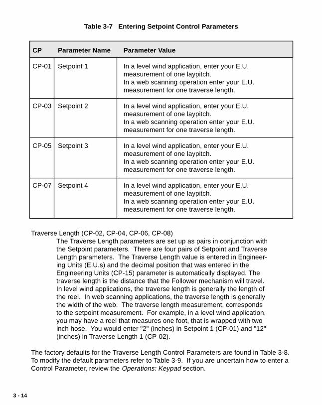
Table 3-7 Entering Setpoint Control Parameters
CP Parameter Name Parameter Value
CP-01 Setpoint 1 In a level wind application, enter your E.U.measurement of one laypitch.In a web scanning operation enter your E.U.measurement for one traverse length.
CP-03 Setpoint 2 In a level wind application, enter your E.U.measurement of one laypitch.In a web scanning operation enter your E.U.measurement for one traverse length.
CP-05 Setpoint 3 In a level wind application, enter your E.U.measurement of one laypitch.In a web scanning operation enter your E.U.measurement for one traverse length.
CP-07 Setpoint 4 In a level wind application, enter your E.U.measurement of one laypitch.In a web scanning operation enter your E.U.measurement for one traverse length.
Traverse Length (CP-02, CP-04, CP-06, CP-08)The Traverse Length parameters are set up as pairs in conjunction withthe Setpoint parameters. There are four pairs of Setpoint and TraverseLength parameters. The Traverse Length value is entered in Engineer-ing Units (E.U.s) and the decimal position that was entered in theEngineering Units (CP-15) parameter is automatically displayed. Thetraverse length is the distance that the Follower mechanism will travel.In level wind applications, the traverse length is generally the length ofthe reel. In web scanning applications, the traverse length is generallythe width of the web. The traverse length measurement, correspondsto the setpoint measurement. For example, in a level wind application,you may have a reel that measures one foot, that is wrapped with twoinch hose. You would enter "2" (inches) in Setpoint 1 (CP-01) and "12"(inches) in Traverse Length 1 (CP-02).
The factory defaults for the Traverse Length Control Parameters are found in Table 3-8.To modify the default parameters refer to Table 3-9. If you are uncertain how to enter aControl Parameter, review the Operations: Keypad section.

3 - 15
Table 3-8 Default Traverse Length Control Parameters
CP Parameter Name Parameter Value
CP-02 Traverse Length 1 0.000
CP-04 Traverse Length 2 0.000
CP-06 Traverse Length 3 0.000
CP-08 Traverse Length 4 0.000
Table 3-9 Entering Traverse length Control Parameters
CP Parameter Name Parameter Value
CP-02 Traverse Length 1 In a level wind application, enter your reel length inE.U.s (reference Setpoint 1).In a web scanning operation, enter the width of yourweb, in E.U.s (reference Setpoint 1).
CP-04 Traverse Length 2 In a level wind application, enter your reel length inE.U.s (reference Setpoint 2).In a web scanning operation, enter the width of yourweb, in E.U.s (reference Setpoint 2).
CP-06 Traverse Length 3 In a level wind application, enter your reel length inE.U.s (reference Setpoint 3).In a web scanning operation, enter the width of yourweb, in E.U.s (reference Setpoint 3).
CP-08 Traverse Length 4 In a level wind application, enter your reel length inE.U.s (reference Setpoint 4).In a web scanning operation, enter the width of yourweb, in E.U.s (reference Setpoint 4).

3 - 16
The following chart demonstrates how Setpoint and Traverse Lengthpairs are selected by the various positions of the Setpoint Select A andSetpoint Select B discrete inputs.
Setpoint Select AOpen
Setpoint Select AClosed
Setpoint Select BOpen
Setpoint Select BOpen
Setpoint Select BClosed
Setpoint 1(CP-01)Traverse Length 1(CP-02)
Setpoint 2 (CP-03)Traverse Length 2 (CP-04)
Setpoint 3 (CP-05)Traverse Length 3 (CP-06)
Setpoint 4 (CP-07)Traverse Length 4 (CP-08)
(Closed = shorted to common)

3 - 17
Follower Profile Parameters
In addition to being part of a setpoint pair, the traverse length acts in conjunction withthe Accel/Decel Length (CP-09) parameter and the Dwell (CP-10) parameter to definethe Follower Profile. The Follower Profile creates a smooth transition to dwell beforereversing directions. This takes place at the reel's end in level wind applications or atthe edge of the web in web scanning applications.
Accel/Decel Length (CP-09)
The Accel/Decel Length (CP-09) parameter allows the Follower mecha-nism to ramp to either the constant pitch plateau or end dwell, eithergradually or rapidly. This parameter is the number of encoder lines forthe desired Accel/Decel Length. The lower the number, the morerapidly the Follower mechanism ramps to the constant pitch plateau orend dwell. The higher the number, the more gradually the Followermechanism ramps to the control pitch plateau or end dwell. As aguideline, keep in mind that you do not want the accel/decel rate toexceed the load that the motor drive or mechanics can accommodate.The Accel/Decel Length parameter does not need to be an exactnumber, the system will perform adequately with a close estimate.
The factory default for the Accel/Decel Length Control Parameter is found in Table 3-10.To modify the default parameter refer to Table 3-11. If you are uncertain how to enter aControl Parameter, review the Operations: Keypad section.
Table 3-10 Default Accel/Decel Length Control Parameter
CP Parameter Name Parameter Value
CP-09 Accel/Decel Length 0
Table 3-11 Entering Accel/Decel Length Control Parameter
CP Parameter Name Parameter Value
CP-09 Accel/Decel Length Enter the number of encoder lines for the desiredAccel/Decel Length.

3 - 18
Dwell (CP-10)
The Dwell (CP-10) parameter allows the Follower mechanism to pauseat the end of the Follower profile before ramping back in the oppositedirection. In level wind applications, this parameter is a portion of theencoder lines in one rotation of the reel (Lead). In web scanningapplications, this parameter is a portion of the encoder lines in onetraverse length. The Dwell parameter does not need to be an exactnumber, the system will perform adequately with a close estimate .
The factory default for the Dwell Control Parameter is found in Table 3-12. To modifythe default parameter refer to Table 3-13. If you are uncertain how to enter a ControlParameter, review the Operations: Keypad section.
Table 3-12 Default Dwell Control Parameter
CP Parameter Name Parameter Value
CP-10 Dwell 0
Table 3-13 Entering Dwell Control Parameter
CP Parameter Name Parameter Value
CP-10 Dwell In a level wind applications, enter a portion of theencoder lines in one rotation of the reelIn a web scanning applications, enter a portion of theencoder lines in one traverse length.

3 - 19
Other Follower Parameters
The orientation (edge or center) of “Home,” changes in the “Home” position andchanges made on the fly, are determined by the following parameters:
Edge/Center Based Profile (CP-24)The traverse length is measured from “Home”. The Edge/Center BasedProfile (CP-24) parameter allows you to set “Home” relative to either theedge or the center of your reel or web. The Follower mechanismmoves a traverse length from that position and then returns.
To set “Home” as an edge based profile, enter “1” in CP-24. Alltraverse length changes occur from the edge, in the forward directionand the “Home” position does not change. The diagram below illus-trates this profile. Traverse length changes can be made on the fly andthe timing on these changes is a crucial factor. For the timing on edgebased traverse length changes, refer to the Change Activation (CP-25)parameter.
12" Traverse Length
10" Traverse Length
5" Traverse Length
Edge Based“Home”
To set “Home” as a center based profile, enter “2” in CP-24. Alltraverse length changes occur from the center and the “Home” positionchanges to compensate for traverse length changes. The diagrambelow illustrates this profile. Traverse length changes will occur auto-matically when the Follower mechanism is in the center of the web.
12" Traverse Length
10" Traverse Length
5" Traverse Length
Center Based
“Home”
“Home”
“Home”
CL

3 - 20
Change Activation (CP-25)The Change Activation (CP-25) parameter works in conjunction with theEdge/Center Based Profile (CP-24) parameter. When CP-24 is set to“1” (edge based), then CP-25 determines when changes will occur. IfCP-24 is set to “2” (center based), then CP-25 has no effect.
Change Activation (CP-25) can be set to “1”, “2” or “3”. Settings “2” and“3” have a number of variables:
If CP-25 is set to “1” then all of the changes will occur when the Fol-lower is at “Home”.
If CP-25 is set to “2” and either the Accel/Decel Length or Dwell param-eters are changed, the changes will only occur at “Home”.
If CP-25 is set to “2” and the setpoint speed is changed (either faster orslower), the change will occur immediately, but only if the changeoccurs within the new constant pitch plateau of the profile. Otherwisesetpoint speed changes occur at “Home”.
If CP-25 is set to “2” and the traverse length is changed, the changewill occur immediately, but only if the longer change occurs within theold constant pitch plateau and a shorter change occurs within the newconstant pitch plateau of the profile, and either change is in a forwarddirection. Otherwise traverse length changes occur at “Home”.
If CP-25 is set to “2” and both the traverse length and the setpointspeed are changed, then use the switches to make the changes andstay within the profile parameters listed above for setpoint speed andtraverse length changes. When any of the changes are not within thespecified plateaus of the profile, then the changes will occur when theFollower mechanism reaches “Home”. Refer to the diagrams below.
Setpoint Changes
acce
l/dec
el
accel/decel
Dwell
NewPlateau
Faster
Slower
NewPlateau
Traverse LengthChanges
acce
l/dec
el
accel/decel
Dwell
NewPlateau
Shorter Longer
NewPlateau

3 - 21
If CP-25 is set to “3”, the change will occur at the next forward orreverse dwell position. However, if there is no dwell position, a setpointchange will occur at the start of the reverse plateau in the forwarddirection or at the start of the forward plateau in the reverse direction. Ifthe setpoint is changed to a slower speed, this change will cause aspike, which will momentarily cause an abrupt jolt to the Followermechanism. Therefore, for a smooth operation, it is best to specify aDwell (CP-10) parameter.
At-Home Band (CP-30)The At-Home Band (CP-30) parameter allows for a certain amount of“range” in the Home position, measured in encoder lines. Although theHome Set and Home Seek inputs place home exactly at “0”, the At-Home Band parameter allows home to be located in a band that ismeasured in negative and positive encoder lines on each side of the "0"mark. Enter the desired number of encoder lines in CP-30.
NOTE: The Follower mechanism must be positioned within the At-Home Band before “Run” is entered. The Follower position must alsobe within the At-Home band to activate the At-Home LED indicator(front panel) and the At-Home discrete output.
The factory defaults for the Edge/Center Based Profile, Home Offset, ChangeActivation and At-Home Band Control Parameters are found in Table 3-14. To modifythe default parameters refer to Table 3-15. If you are uncertain how to enter a ControlParameter, review the Operations: Keypad section.

3 - 22
Home Offset (CP-31)The Home Offset parameter allows you to offset the “Home” positionand relocate it somewhere other than the sensor.
If CP-24 is set at “1” (edge based), measure the distance from thesensor to the desired position of “Home”. Enter that E.U. amount inCP-31.
Sensor
DIRECTIONOF WIND
Home
Edge Based Home Offset
(CP-31)
FOLLOWER LEAD
If CP-24 is set at “2” (center based), measure the distance from thesensor to the center. Enter that E.U. amount in CP-31. TheM-Traverse will make a transparent, internal calculation and position“Home” at a distance that is CP-31 minus 1/2 of the traverse length.The position of “Home” will change to correspond with any changes inthe traverse length.
Sensor
LINE FLOW
FOLLOWER
LEAD
Home
CL
Center Based Home Offset
(CP-31)
NOTE: Since the “Home” position calculations are dependent on theTraverse Length (CP-02, CP-04, CP-06, CP-08) parameter and the Engineer-ing Units (CP-15) parameter, those values must have already been enteredprior to entering a value in CP-31. To enter these parameters, refer to theOperations: Control Parameters section.

3 - 23
Table 3-14 Default Control Parameters for Changes
CP Parameter Name Parameter Value
CP-24 Edge/Center Based 1
CP-25 Change Activation 1
CP-30 At-Home Band 4
CP-31 Home Offset 0
Table 3-15 Entering Control Parameters for Changes
CP Parameter Name Parameter Value
CP-24 Edge/Center Based Enter “1” for an edge based profile.Enter “2” for a center based profile.
CP-25 Change Activation When CP-24 is set to “1” (edge based), then:Enter “1” to activate changes when the Follower is inthe “Home position.Enter “2” to activate changes immediately.Enter “3” to activate changes when the Follower is inthe end dwell position.
CP-30 At-Home Band Enter the number of encoder lines that you want toallow on either side of the “0” Home Set position.
CP-31 Home Offset If CP-24 is set at “1” (edge based), enter the distancefrom the sensor to the desired position of “Home”.If CP-24 is set at “2” (center based), enter the distancefrom the sensor to the center of the web.

3 - 24
The Resume Enable parameter allows you to specify the conditions under which youresume operation.
Resume Enable (CP-32)If you interrupt the operation (F-Stop), the Resume Enable (CP-32)parameter allows you to keep track of error in both the Follower andLead positions. It also allows you to freeze the Lead position and keeptrack of error in the Follower position. The M-Traverse will adjust for theerror when you resume operation.
Resume is disabled by entering "1" in CP-32.To keep track of error in both the Follower and Lead positions enter "2"in CP-32.To freeze the Lead position and keep track of error in the Followerposition, enter “3” in CP-32.
Both the Follower and the Lead information is saved at power-down. Ifthere has been no change in the mechanical position at power-down,then the profile can be resumed at power-up.
If the mechanical position has changed and you resume operation, theFollower could make an abrupt shift to resolve the position error. Thiscan severely injure you or damage the equipment. The specific conse-quences of this abrupt shift can vary, depending on your use of theequipment and your system's design. Install safety equipment that isappropriate for your application.
The factory default for the Resume Enable Control Parameter is found in Table 3-16.To modify the default parameter refer to Table 3-17. If you are uncertain how to enter aControl Parameter, review the Operations: Keypad section.
DANGER
When you resume operationthe Follower could make anabrupt shift.
This can cause severe injury ordamage equipment.
Install safety equipment that isappropriate for your application.
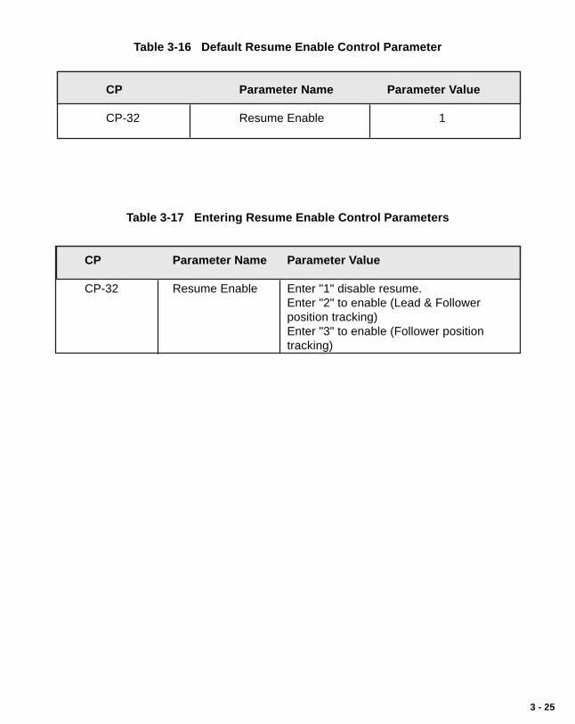
3 - 25
Table 3-16 Default Resume Enable Control Parameter
CP Parameter Name Parameter Value
CP-32 Resume Enable 1
Table 3-17 Entering Resume Enable Control Parameters
CP Parameter Name Parameter Value
CP-32 Resume Enable Enter "1" disable resume.Enter "2" to enable (Lead & Followerposition tracking)Enter "3" to enable (Follower positiontracking)

3 - 26
The polarity type and direction are determined by the following Control Parameters:
Home Sync Polarity (CP-35)The Home Sync Polarity (CP-35) parameter allows you to choosebetween rising edge polarity (positive going signal) or falling edgepolarity (negative going signal) during "Home Seek". This feature isextremely useful when you use reflective or transmissive opticalsensors for the Home sensor. Enter "1" in CP-35 for a rising edge, or"2" for a falling edge. Refer to the diagram below.
Rising Edge Falling Edge
+ Vdc+ Vdc
0 Vdc0 Vdc/ /
Forward/Reverse Limit Polarity (CP-36)The Forward/Reverse Polarity Limit (CP-36) parameter allows you tochoose between rising edge polarity (positive going signal) or fallingedge polarity (negative going signal) so that the Follower mechanismwill not travel beyond the traverse length limit. This feature is ex-tremely useful when you use reflective or transmissive optical sensorsfor the Home sensor. Enter "1" in CP-35 for a rising edge, or "2" for afalling edge.
The factory default for the Polarity Control Parameters are found in Table 3-18. Tomodify the default parameters refer to Table 3-19. If you are uncertain how to enter aControl Parameter, review the Operations: Keypad section.

3 - 27
Table 3-18 Default Polarity Control Parameters
CP Parameter Name Parameter Value
CP-35 Home Sync Polarity 1
CP-36 Fwd/Rev Limit Polarity 2
Table 3-19 Entering Polarity Control Parameters
CP Parameter Name Parameter Value
CP-35 Home Sync Polarity Enter “1” for Rising Edge
Enter “2” for Falling Edge
CP-36 Fwd/Rev Limit Polarity Enter “1” for Rising Edge
Enter “2” for Falling Edge
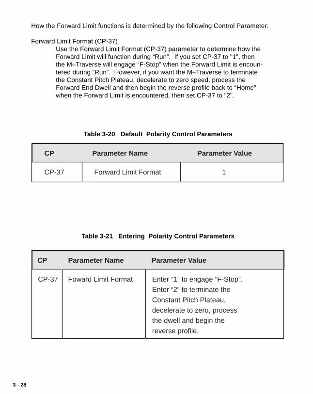
3 - 28
How the Forward Limit functions is determined by the following Control Parameter:
Forward Limit Format (CP-37)Use the Forward Limit Format (CP-37) parameter to determine how theForward Limit will function during “Run”. If you set CP-37 to "1", thenthe M–Traverse will engage “F-Stop” when the Forward Limit is encoun-tered during “Run”. However, if you want the M–Traverse to terminatethe Constant Pitch Plateau, decelerate to zero speed, process theForward End Dwell and then begin the reverse profile back to “Home”when the Forward Limit is encountered, then set CP-37 to "2".
Table 3-20 Default Polarity Control Parameters
CP Parameter Name Parameter Value
CP-37 Forward Limit Format 1
Table 3-21 Entering Polarity Control Parameters
CP Parameter Name Parameter Value
CP-37 Foward Limit Format Enter “1” to engage ”F-Stop”.
Enter “2” to terminate the
Constant Pitch Plateau,
decelerate to zero, process
the dwell and begin the
reverse profile.

3 - 29
DIRECT MODE
The Direct mode is used to calibrate and troubleshoot the M-Traverse. In the Directmode of operation, you can set the level of the Speed Command Out directly from theM-Traverse to the motor drive. The Direct mode is an open-loop mode of operation.Therefore, Scaling, Accel/Decel, and closed loop compensation (PI) algorithms arebypassed in the Direct mode. The Direct mode is used in conjunction with the Run andthe Stop controls.Caution: To avoid damage to your system, the M-Traverse must be calibrated and the
motor drive set up before you enter the Direct mode. Refer to Installation/Setup: Calibration.
The Direct Analog Command (CP-62) parameter uses the full 12 bit resolution of theanalog Speed Command Output.
A value of 4095 is a 100% forward output command.A value of 2048 is a 50% forward output command.0 is a zero output command.
A negative value indicates a reverse output command (e.g., - 4095 is a 100% reversecommand).
To enable the Direct mode, enter "2" the Control Mode (CP-14) parameter.
The factory default Direct Mode Control Parameters are found in Table 3-20. To modifythe default parameters, refer to Table 3-21. If you are uncertain how to enter a ControlParameter, review the Operations: Keypad section.
Table 3-22 Default Direct Mode Control Parameters
CP Parameter Name Parameter Value
CP-62 Direct Analog Command 0
CP-14 Control Mode 1
Table 3-23 Entering Direct Mode Control Parameters
CP Parameter Name Parameter Value
CP-62 Direct Analog Cmd Enter the DAC bits of the calitrated full scale Speed Command Out at which you want your system to operate.
CP-14 Control Mode Enter “2” to enable the Direct Mode (disablesboth Follower Mode options).

3 - 30
JOG
When you activate Jog, the RPM increase at the acceleration rate that you specified inthe Accel/Decel (CP-60) parameter until the Jog Setpoint (CP-61) is achieved. Jog canonly be entered from F-Stop and when Jog is terminated, the Follower mechanismreturns to F-Stop. Jog is used when you need brief bursts of speed to align theFollower mechanism.
The factory default Jog Control Parameters are found in Table 3-22. To modify thesedefault parameters, refer to Table 3-23. If you are uncertain how to enter a ControlParameter, review the Operations: Keypad section.
Table 3-24 Default Jog Control Parameters
CP Parameter Name Parameter Value
CP-61 Jog Setpoint 50
CP-60 Accel/Decel 5.0
Table 3-25 Entering Jog Control Parameters
CP Parameter Name Parameter Value
CP-61 Jog Setpoint Enter the RPM at which you want your system tooperate when it is in Jog.
CP-60 Accel/Decel Enter the number of seconds in which you want yoursystem to accelerate from zero RPM to the Jog Setpointspeed.

3 - 31
—NOTES—
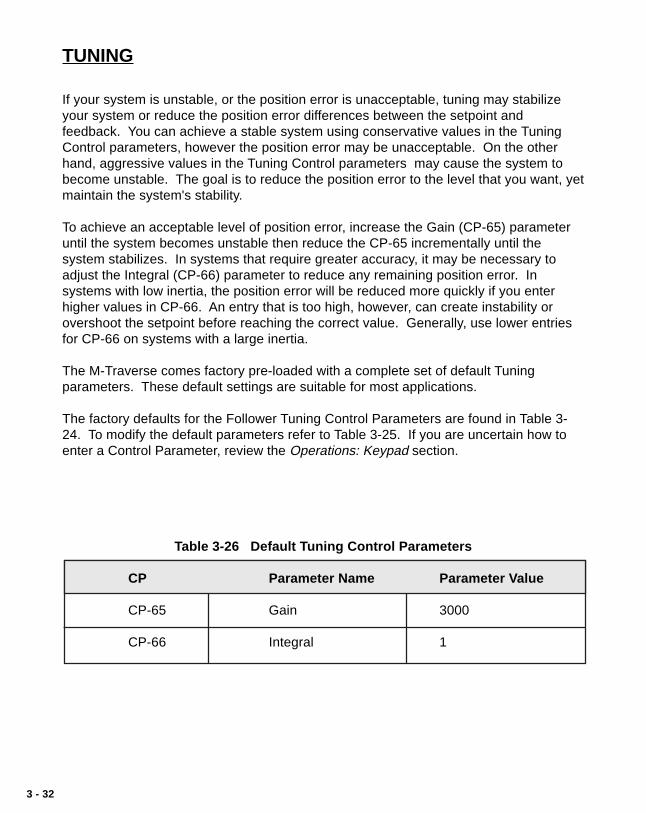
3 - 32
TUNING
If your system is unstable, or the position error is unacceptable, tuning may stabilizeyour system or reduce the position error differences between the setpoint andfeedback. You can achieve a stable system using conservative values in the TuningControl parameters, however the position error may be unacceptable. On the otherhand, aggressive values in the Tuning Control parameters may cause the system tobecome unstable. The goal is to reduce the position error to the level that you want, yetmaintain the system's stability.
To achieve an acceptable level of position error, increase the Gain (CP-65) parameteruntil the system becomes unstable then reduce the CP-65 incrementally until thesystem stabilizes. In systems that require greater accuracy, it may be necessary toadjust the Integral (CP-66) parameter to reduce any remaining position error. Insystems with low inertia, the position error will be reduced more quickly if you enterhigher values in CP-66. An entry that is too high, however, can create instability orovershoot the setpoint before reaching the correct value. Generally, use lower entriesfor CP-66 on systems with a large inertia.
The M-Traverse comes factory pre-loaded with a complete set of default Tuningparameters. These default settings are suitable for most applications.
The factory defaults for the Follower Tuning Control Parameters are found in Table 3-24. To modify the default parameters refer to Table 3-25. If you are uncertain how toenter a Control Parameter, review the Operations: Keypad section.
Table 3-26 Default Tuning Control Parameters
CP Parameter Name Parameter Value
CP-65 Gain 3000
CP-66 Integral 1

3 - 33
Table 3-27 Entering Tuning Control Parameters
CP Parameter Name Parameter Value
CP-65 Gain With Integral (CP-66) set to “0” , increase the Gainparameter value until the system becomes unstable,then decrease it slightly until the system stabilizes.Larger values will increase Gain. To verify the stabilityof the speed changes, you can access Tach througheither the Tach key or the Tach (MV-40) parameter.
CP-66 Integral While switching between the high and low setpoints,increase the Integral's default value of “1” until theposition error is reduced within an acceptable timeframe. To verify the stability of the speed changes, youcan access Tach through either the Tach key or theTach (MV-40) parameter.

3 - 34
OUTPUT CONTROL
Output Control is influenced by the Batch Control Parameters, the Alarm Output, theAt-Home output and Outputs A and B. These parameters and outputs are discussed asfollows:
The Batch Control Parameters allow you to make a specific amount of product andthen automatically stop when that amount is reached.
Batch Format (CP-26)Use the Batch Format (CP-26) parameter to indicate which type ofcount that you want the Batch Counter to do. You can count eitherFollower traverses or Lead reel revolutions. Enter “1” in CP-26 to countthe Follower traverses. Enter “2” in CP-26 to count Lead revolutions.
Batch Limit (CP-27)The Batch Counter is an up-counter that is cleared to zero by the BatchReset input. Use the Batch Done Output to shut off the system whenthe Batch Count has been reached. You can count either the number ofFollower traverses or the number of Lead reel revolutions. If you countFollower traverses, each direction counts as one traverse. If you countLead revolutions, each wrap of the reel (or layer), is one lead revolu-tion. Enter the total number that you want counted in Batch Limit (CP-27).
Batch PreAct Distance (CP-28)The Batch PreAct Distance (CP-28) parameter is used only if the BatchFormat (CP-26) has been set to number “1” (Follower traverses). CP-28 allows you to set a specific distance at which to activate the BatchDone. This can be at the end dwell or any distance from dwell, up tothe Accel/Decel Length at the opposite end from dwell. If you enter anumber that would go beyond the Accel/Decel Length, the M-Traversewill automatically default to the Accel/Decel Length. For example, yourreel is 10 inches long, with an Accel /Decel Length of 1 inch on eachend, and the laypitch profile is 8 inches. CP-28 will default at 9 inchesfor any amount above 9 inches that you enter in CP-28, because theopposite Accel /Decel is 9 inches from the dwell. See the diagrambelow for a profile representation of this example:
Laypitch
Acc
el/D
ecel
Accel/D
ecel Dwell
1" 8" 1"
9"

3 - 35
The factory defaults for the Batch Control Parameters are found in Table 3-26. Tomodify the default parameters refer to Table 3-27. If you are uncertain how to enter aControl Parameter, review the Operations: Keypad section.
Table 3-28 Default Batch Control Parameters
CP Parameter Name Parameter Value
CP-26 Batch Format 1
CP-27 Batch Limit 0
CP-28 Batch PreAct Distance 999999
Table 3-29 Entering Batch Control Parameters
CP Parameter Name Parameter Value
CP-26 Batch Format Enter “1” in CP-26 for Follower traverses.Enter “2” in CP-26 for Lead reel revolutions.
CP-27 Batch Limit Enter the total number of Follower traverses or Leadreel revolutions that you want counted.
CP-28 Batch PreAct Dist Enter a specific preact distance at which to activate theBatch Done (only if CP-26 is set at “1”).

3 - 36
The Alarm Output allows you to set a high speed RPM indication.
High Speed Alarm (CP-23)Use the High Speed Alarm (CP-23) parameter to determine the RPMlevel that will activate the High Speed Alarm Output. When theFollower's motor RPM are at or above the value in CP-23, the HighSpeed Alarm Output will activate.
The factory default for the Default Alarm Control Parameter is found in Table 3-28. Tomodify the default parameter refer to Table 3-29. If you are uncertain how to enter aControl Parameter, review the Operations: Keypad section.
Table 3-30 Default Alarm Control Parameter
CP Parameter Name Parameter Value
CP-23 High Speed Alarm 2000
Table 3-31 Entering Alarm Control Parameter
CP Parameter Name Parameter Value
CP-23 High Speed Alarm Enter the RPM limit that will activate the High SpeedAlarm Output.

3 - 37
The At-Home Output activates in response to the At-Home Band parameter.
At-Home Band (CP-30)When the Follower is within the At-Home Band, the At-Home Outputwill be activated. The At-Home Band (CP-30) parameter allows for acertain amount of “range” in the Home position, measured in encoderlines. Although the Home Set input places home exactly at “0”, the At-Home Band (CP-30) allows home to be located in a band that is mea-sured in negative and positive encoder lines on each side of the "0"mark. The desired number of encoder lines is entered in CP-30.
NOTE: The Follower must be within the At-Home Band before “Run”is entered. The Follower position must also be within the At-Home bandto activate the front panel At-Home LED indicator and the At-Homediscrete output.
The factory default for the At-Home Band Control Parameter is found in Table 3-30. Tomodify the default parameter refer to Table 3-31. If you are uncertain how to enter aControl Parameter, review the Operations: Keypad section.
Table 3-32 Default At-Home Band Control Parameter
CP Parameter Name Parameter Value
CP-30 At-Home Band 4
Table 3-33 Entering At-Home Band Control Parameter
CP Parameter Name Parameter Value
CP-30 At-Home Band Enter the number of encoder lines that you want to allowon either side of the “0” Home Set position.

3 - 38
Output A activates peripheral equipment in response to the Output A parameters. Thisperipheral equipment can be set up to add material (e.g., adhesive or paint) duringspecific segments of the Follower profile.
Output A Segment (CP-90)Use the Output A Segment (CP-90) parameter to determine whatsegment of the Follower profile will activate Output A.
Enter “1” in CP-90 to activate Output A during the constant pitch plateausegment of the Follower profile.Enter “2” in CP-90 to activate Output A during the constant pitch andAccel/Decel segments of the Follower profile.Enter “3” in CP-90 to activate Output A during the dwell segment of theFollower profile.
The diagram below illustrates the segments of the Follower profile :
ConstantPitch
Plateau
Follower Profile
Acc
el/D
ecel
Accel/D
ecel Dwell
1
2
3
Output A Direction (CP-91)Use the Output A Direction (CP-91) parameter to specify the direction inwhich Output A will operate.
Enter “1” in CP-91 to activate Output A during the forward direction.Enter “2” in CP-91 to activate Output A during the reverse direction.Enter “3” in CP-91 to activate Output A during the forward and reversedirections.
Output A Polarity (CP-92)Use the Output A Polarity (CP-92) parameter to specify the voltagepolarity at which Output A will operate.
Enter “0” in CP-92 to activate Output A as Active Low Voltage Level.Enter “1” in CP-92 to activate Output A as Active High Voltage Level.
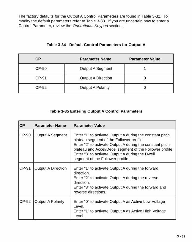
3 - 39
The factory defaults for the Output A Control Parameters are found in Table 3-32. Tomodify the default parameters refer to Table 3-33. If you are uncertain how to enter aControl Parameter, review the Operations: Keypad section.
Table 3-34 Default Control Parameters for Output A
CP Parameter Name Parameter Value
CP-90 Output A Segment 1
CP-91 Output A Direction 0
CP-92 Output A Polarity 0
Table 3-35 Entering Output A Control Parameters
CP Parameter Name Parameter Value
CP-90 Output A Segment Enter “1” to activate Output A during the constant pitchplateau segment of the Follower profile.Enter “2” to activate Output A during the constant pitchplateau and Accel/Decel segment of the Follower profile.Enter “3” to activate Output A during the Dwellsegment of the Follower profile.
CP-91 Output A Direction Enter “1” to activate Output A during the forwarddirection.Enter “2” to activate Output A during the reversedirection.Enter “3” to activate Output A during the forward andreverse directions.
CP-92 Output A Polarity Enter “0” to activate Output A as Active Low VoltageLevel.Enter “1” to activate Output A as Active High VoltageLevel.

3 - 40
Output B activates peripheral equipment in response to the Output B parameters. Thisperipheral equipment can be set up to add material (e.g., adhesive or paint) duringspecific segments of the Follower profile.
Output B Segment (CP-93)Use the Output B Segment (CP-93) parameter to determine whatsegment of the Follower profile will activate Output B.
Enter “1” in CP-93 to activate Output B during the constant pitch plateausegment of the Follower profile.Enter “2” in CP-93 to activate Output B during the constant pitch plateauand Accel/Decel segments of the Follower profile.Enter “3” in CP-93 to activate Output B during the dwell segment of theFollower profile.
The diagram below illustrates the segments of the Follower profile :
ConstantPitch
Plateau
Follower Profile
Acc
el/D
ecel
Accel/D
ecel Dwell
1
2
3
Output B Direction (CP-94)Use the Output B Direction (CP-94) parameter to specify the direction inwhich Output B will operate.
Enter “1” in CP-94 to activate Output B during the forward direction.Enter “2” in CP-94 to activate Output B during the reverse direction.Enter “3” in CP-94 to activate Output B during the forward and reversedirections.
Output B Polarity (CP-95)Use the Output B Polarity (CP-95) parameter to specify the voltagepolarity at which Output B will operate.
Enter “0” in CP-95 to activate Output B as Active Low Voltage Level.Enter “1” in CP-95 to activate Output B as Active High Voltage Level.

3 - 41
The factory defaults for the Output B Control Parameters are found in Table 3-34. Tomodify the default parameters refer to Table 3-35. If you are uncertain how to enter aControl Parameter, review the Operations: Keypad section.
Table 3-36 Default Control Parameters for Output B
CP Parameter Name Parameter Value
CP-93 Output B Segment 1
CP-94 Output B Direction 0
CP-95 Output B Polarity 0
Table 3-37 Entering Output B Control Parameters
CP Parameter Name Parameter Value
CP-93 Output B Segment Enter “1” to activate Output B during the constant pitchplateau segment of the Follower profile.Enter “2” to activate Output B during the constant pitchplateau and Accel/Decel segment of the Follower profile.Enter “3” to activate Output B during the Dwellsegment of the Follower profile.
CP-94 Output B Direction Enter “1” to activate Output B during the forwarddirection.Enter “2” to activate Output B during the reversedirection.Enter “3” to activate Output B during the forward andreverse directions.
CP-95 Output B Polarity Enter “0” to activate Output B as Active Low VoltageLevel.Enter “1” to activate Output B as Active High VoltageLevel.

3 - 42
—NOTES—

3 - 43
M–TRAVERSE OPERATION
The M–Traverse Operation section addresses the six modes that control theM–Traverse's operation. This section explains the function of each of these modes andhow to use the modes for your specific system application. Diagrams are included toillustrate the profile sequences.
The six modes are:
Follower Mode (Standard or Lay Adjusted)Home SetHome SeekHome ReturnDirect ModeJog

3 - 44
FOLLOWER MODE (WEB SCANNING OR LEVEL WIND)
The M–Traverse is specifically designed for the precise control of reciprocating lead/follower motion control applications. Its primary mode of operation is the Followermode. The Run input (J4, pins 6,7) activates the Follower mode when the followingconditions have already been established:
• The Control Mode (CP-14) is set to the Follower mode:“1” for Standard.“3” for Lay Adjusted.
• The M–Traverse is either in F-Stop or a position hold state.• The Follower mechanism is within the At-Home Band (CP-30).• MV-58 displays “0”, indicating that there is a valid Follower profile.
When the Follower mode has been activated, the Follower mechanism will begin tomove from “Home” in a forward direction (toward the Forward Limit). As the Followermechanism travels along the Traverse Length (CP-02, CP-04, CP-06, or CP-08), itaccelerates for the specified Accel/Decel Length (CP-09) then travels the constant pitchplateau at the Process Ratio (MV-86). At the end of the constant pitch plateau, theFollower mechanism decelerates the specified Accel/Decel Length (CP-09) to Dwell(CP-10). The Follower mechanism remains at zero speed for the specified Dwell thenrepeats the same profile in reverse. If the Wait input (J4, pins 7, 8) is shorted tocommon (low) the Follower mechanism will pause at the closest end of the profile untilthe Wait input is open (high). The Drive Enable discrete output is active during theFollower mode.
Caution: To avoid damage to your system, the M–Traverse must be calibrated and themotor drive set up before you enter the Follower mode. Refer to Installation/Setup: Calibration.
The following diagram illustrates the Follower profile:
Traverse LengthAccel/Decel
(CP-09)
Follower/LeadRatio
HomeSync
Sensor
Forward
Constant PitchPlateau
Dwell(CP-10)
Reverse
Traverse LengthAccel/DecelLength(CP-09)
Accel/Decel
(CP-09)
Dwell(CP-10)
Dwell(CP-10)
Constant PitchPlateauProcess
Ratio(MV-86)
Accel/DecelLength(CP-09)

3 - 45
HOME SET
Home Set is one of two ways in which you can establish “Home” (Home Seek is theother way). When the Home Set input is closed, it sets the current position of theFollower mechanism as “Home”. Home Set will establish “Home” at any arbitraryposition that you choose. You can use the Jog input to position the Followermechanism or you can position it manually.
Home Set enables the Drive Enable logic output, which allows the Follower mechanismto hold its position at “Home” despite any outside force (such as gravity). The HomeSet is a momentary input that is edge triggered and is activated through the Home Setinput (J3, pin 14,16).
NOTE: “Home” must be established before the Follower mode can be used. “Home”is identified by a Follower position of zero. In the Follower mode, “Home” isthe position from which the profile traverses in the Forward direction.
HOME SEEK
Home Seek also establishes “Home”. Home Seek finds and sets “Home” by locatingthe Home Sync Sensor. When the Home Seek input is closed, the Followermechanism makes a profiled move at jog speed, until it aligns with the Home Syncsensor, which then becomes “Home”.
Home Seek enables the Drive Enable logic output, which allows the Followermechanism to hold its position at “Home” despite any outside force (such as gravity).Home Seek is a momentary input that is edge triggered and is activated through theHome Seek input (J4, pin 1, 2). Home Seek is internally latched and does not need tobe maintained by an operator device.
NOTE: “Home” must be established before the Follower mode can be used. “Home”is identified by a Follower position of zero. In the Follower mode, “Home” isthe position from which the profile traverses in the Forward direction.
Home Seek will always begin to move the Follower mechanism in the reverse direction(towards the reverse limit). When Home Seek locates the Home Sync sensor, itramps down at the Accel/Decel rate (CP-60) to zero. This causes the Followermechanism to overshoot the Home Sync sensor and the M–Traverse compensates witha triangulated forward Accel/Decel move that aligns the Follower mechanism with theHome Sync sensor. There are a variety of profile possibilities, since Home Seek canfind home from any position on the traverse length. The following examples willillustrate four possible Home Seek profiles.

3 - 46
Example of an Edge Based Profile with no Home Offset.
Home Seek moves the Follower mechanism in the reverse direction (toward thereverse limit). When Home Seek locates the Home Sync sensor, it ramps down at theAccel/Decel (CP-60) rate to zero. This causes the Follower mechanism to overshootthe Home Sync sensor and the M–Traverse compensates with a forward, triangulatedAccel/Decel move that aligns the Follower mechanism with the Home Sync sensor.This profile is used in both web scan and level wind applications.
Jog Speed(CP-61)
Acc
el/D
ecel
(CP
-60)
Accel/D
ecel
(CP
-60)
Start Here
ForwardLimit
ReverseLimit
HomeSyncSensor

3 - 47
Example of an Edge Based Profile with Home Offset.
Home Seek moves the Follower mechanism in the reverse direction, bypasses theHome Sync sensor, and establishes “Home” at the Home Offset position. The HomeOffset position is measured in E.U.s and is the length away from the Home Sync sensorthat has been specified in the Home Offset (CP-31) parameter. When Home Seeklocates the Home Offset position, it ramps down at the Accel/Decel rate (CP-60) tozero. This causes the Follower mechanism to overshoot the Home Offset position. TheM–Traverse compensates by continuing Home Seek in a forward, triangulated Accel/Decel move that aligns the Follower mechanism with the Home Offset and establishes“Home” . This profile is commonly used for applications that can not establish “Home”at the Home Sync sensor because of interference (e.g., the physical edge of the reel ora bracket that is in the way). This profile is used in both web scan and level windapplications.
Jog Speed(CP-61)
Acc
el/D
ecel
(CP
-60)
Accel/D
ecel
(CP
-60)
Start Here
HomeOffset(CP-31)
HomeSync
Sensor
ForwardLimit
ReverseLimit
Home

3 - 48
Example of a Center Based Profile with Home Offset.
Home Seek moves the Follower mechanism in the reverse direction, detects the HomeSync sensor, then ramps down at the Accel/Decel rate (CP-60) to zero. Then theM–Traverse makes a forward, triangulated move (in the forward direction) to the“Home” position. The M–Traverse uses Home Sync as the starting point anddetermines the “Home” position by subtracting is one-half of the Traverse Length fromHome Offset (CP-31).
Jog Speed(CP-61)
Acc
elD
ecel
(CP
-60)A
ccel/Decel
(CP
-60)
Start Here
Home Offset(CP-31)
HomeSync
Sensor
ForwardLimit
ReverseLimit
*Home (Subtract one-half traverse length from CP-31)
1/2TraverseLength

3 - 49
Example of an Edge Based Profile with Reverse Rebound.
Home Seek moves the Follower mechanism in the reverse direction. Home Seekreaches the Reverse Limit without detecting the Home Sync sensor and immediatelystops. Home Seek moves the Follower mechanism in the forward direction (toward theForward Limit). When Home Seek locates the Home Sync sensor, it ramps down atthe Accel/Decel rate (CP-60) to zero. This causes the Follower mechanism toovershoot the Home Sync sensor. The M–Traverse compensates by reactivating HomeSeek in the reverse direction, then a forward, triangulated Accel/Decel move that alignsthe Follower mechanism with the Home Sync senor. This profile is used in both webscan and level wind applications.
Note : If Home Seek does not detect the Home Sync sensor by the time it reachesthe Forward Limit, the M–Traverse automatically shuts the system off (F-Stop).
Jog Speed(CP-61)
Acce
l/Dec
el(C
P-60
)
Start HereHomeSync
Sensor
ForwardLimit
ReverseLimit
accel/decel
(CP
-60)
Accel/D
ecel
(CP
-60)

3 - 50
HOME RETURN
If “Home” has been established through either Home Set or Home Seek, then HomeReturn can return the Follower mechanism to “Home”. When the Home Return input isclosed, the Follower mechanism makes a profiled move at jog speed until it aligns with“Home”.
The Follower mechanism will move toward “Home”, in either the reverse or forwarddirection, depending on which direction is closer to “Home”. When the Followermechanism travels in the reverse direction to locate “Home”, it ramps down at theAccel/Decel rate (CP-60) to zero. This causes the Follower mechanism to overshootthe Home Sync sensor by a distance that is equal to the At-Home Band (CP-30). TheM–Traverse compensates with a forward, triangulated Accel/Decel move that aligns theFollower mechanism with “Home”.
Jog Speed(CP-61)
Accel
/Dec
el
(CP-6
0)
Accel/Decel
(CP-60)
Start Here
ForwardLimit
ReverseLimit
HomeSync
Sensor
At-HomeBand
(CP-30)
When the Follower mechanism travels in the forward direction to locate “Home”, itdecelerates directly down to the “Home” position from a predetermined position thatramps the Follower directly to the “Home” position.
Jog Speed(CP-61)
Acc
el/D
ecel
(CP
-60)
Accel/D
ecel
(CP
-60)
Start Here
ForwardLimit
ReverseLimit
HomeSync
Sensor
Home Return enables the Drive Enable logic output, which allows the Followermechanism to hold its position at “Home” despite any outside force (such as gravity).The Home Return is a momentary input that is edge triggered and is activated throughthe Home Return input (J4, pin 3, 4). Home Seek is internally latched and does notneed to be maintained by an operator device.

3 - 51
DIRECT MODE
The Direct mode is used to calibrate and troubleshoot the M–Traverse. In the Directmode of operation, you can set the Speed Command Out from the M–Traverse that isconnected to the motor drive, directly. The Direct mode is an open-loop mode ofoperation. Therefore, Scaling, Acceleration/Deceleration, and closed loopcompensation (PI) software are not involved in the Direct mode.
The Direct mode is used in conjunction with the Run and F-Stop controls. The Runinput (J4, pins 6,7) activates the Direct mode when the Control Mode (CP-14)parameter has been set to “2” (enable Direct mode). When the Direct mode has beenactivated, the analog output level goes immediately to the DAC bits specified in theDirect Analog Command (CP-62). The Direct Analog Command (CP-62) parameteruses the full 12 bit resolution of the analog Speed Command Output. A positive valueindicates a forward direction and a negative value indicates a reverse direction. The F-Stop input will move the Speed Command Out to zero immediately.
The Drive Enable logic output is active during Run and deactivated during F-Stop.The Forward and Reverse Limits are also active. If the Follower mechanismencounters a Forward or Reverse Limit, it will immediately stop (F-Stop) and go to zerospeed with no deceleration. The Follower mechanism can be moved away from eitherlimit by any control mode that move the Follower mechanism in the opposite directionfrom the limit. All of the setpoint, Run and F-Stop changes will occur without the Accel/Decel ramps.
Caution: To avoid damage to your system, the M–Traverse must be calibrated and themotor drive set up before you enter the Direct mode. Refer to Installation/Setup: Calibration.

3 - 52
JOG
Jog is used in conjunction with Home Set to move the Follower mechanism to “Home”.Jog can also be used when you need brief bursts of speed to align the Followermechanism. When you activate Jog, the RPMs increase at the acceleration rate thatyou specified in Acceleration/Deceleration (CP-60) until the Jog Setpoint (CP-61) isachieved. When Jog is terminated, the RPMs return to zero immediately, with nodeceleration. The Jog direction is determined by the Jog Forward/Reverse Input (J4,pins 15,16), which controls the direction of the Speed Command Output. The DriveEnable logic output is active during the Jog mode.
Jog (J4, pins 16,17) is a maintained input. When the Jog input is closed, the M–Traverse sends a Speed Command Out signal to the drive at the selected jog speed.As a maintained input, Jog is only active when the operator device is closed.

3 - 53
MONITOR VARIABLES
Parameters are divided into two classifications; Control Parameters (CP) and MonitorVariable (MV). The numbered code that represents the parameter is the ParameterCode. The operational data is the parameter's value.
Control Parameter 14 = 1Parameters =
Monitor Variable 40 = 200
Parameter Code Parameter Value
This section is about Monitor Variables. Control Parameters are explained inOperation: Control Parameters.
The M–Traverse has a number of Monitor Variables (MVs) that monitor theperformance of the M–Traverse and your system, help you troubleshoot for problems,and confirm the wiring and tuning. MVs can be accessed at any time during theM–Traverse's operation, including during Run, Jog, and F–Stop.
Note: Monitor Variables are status indicators only - you can not directly affect an MV.
There are four categories of Monitor Variables:
Input MonitoringOutput MonitoringPerformance MonitoringStatus Monitoring
In the sections that follow, the Monitor Variables are listed according to thesecategories.

3 - 54
INPUT MONITORING
These MVs monitor the M–Traverse's inputs.
MV-41 LEAD FREQUENCY
The Lead Frequency displays the frequency of the Lead Frequency Input (J3, pin 3, 4,5) in hertz (pulses per second). MV-41 is averaged; it is the 250 millisecond frequencycalculation prior to the display update.
MV-42 FEEDBACK FREQUENCY
The Feedback Frequency displays the frequency of the Feedback Frequency Input (J3,pin 7, 8, 9) in hertz (pulses per second). MV-42 is averaged; it is the 250 millisecondfrequency calculation prior to the display update.
MV-53 DISCRETE INPUTS - GROUP A
The Discrete Inputs - Group A displays the status of the Jog, Jog Forward/Reverse,Run, Wait, F-Stop, and Keypad Lockout discrete inputs. The number “1” indicates anopen, or logic high level. The number “0” indicates a closed, or logic low level (shortedto common). In the example below, “Jog Forward/Reverse” is the open or logic highlevel.
JogJog Forward/Reverse
RunWait
F-StopKeypad Lockout

3 - 55
MV-54 DISCRETE INPUTS - GROUP B
The Discrete Inputs - Group B displays the status of the Forward Limit, Reverse Limit,Home Sync, Setpoint Select A and Setpoint Select B discrete inputs. The number “1”indicates an open, or logic high level. The number “0” indicates a closed, or logic lowlevel (shorted to common). In the example below, “Reverse Limit” is the open or logichigh level.
Forward LimitReverse Limit
Not UsedHome Sync
Setpoint Select ASetpoint Select B
MV-55 DISCRETE INPUTS - GROUP C
The Discrete Inputs - Group C displays the status of the Home Set, Home Seek, HomeReturn, and Batch Reset discrete inputs. The number “1” indicates an open, or logichigh level. The number “0” indicates a closed, or logic low level (shorted to common).In the example below, “Home Seek” is the open or logic high level.
Home SetHome Seek
Home ReturnBatch Reset
Not UsedNot Used
.

3 - 56
OUTPUT MONITORING
These MVs monitor the M–Traverse's outputs.
MV-47 DAC OUTPUT
The DAC Output displays the present level of the analog speed command output to themotor drive. The DAC output displays in DAC bits. A value of 4095 indicates a 100%positive output and a value of -4095 indicates a 100% negative output.
MV-48 TRIM OUTPUT
The Trim Output is the calculated output of the compensation algorithm (gain plusintegral). This value is displays in DAC bits. A value of 4095 indicates a 100% positiveoutput and a value of -4095 indicates a 100% negative output.
MV-56 DISCRETE OUTPUTS - GROUP A
The Discrete Output - Group A displays the status of the Drive Enable, Batch Done,Alarm, Profile Direction, At-Home and Output A discrete outputs. The number “1”indicates an inactive or de-energized (logic high) level. The number “0” indicates anactive or energized (logic low) level. In the example below, “Batch Done” is the inactiveor de-energized (logic high) level.
Drive Enable
Batch Done Alarm
Profile Direction At-Home
Output A

3 - 57
MV-57 DISCRETE OUTPUTS - GROUP B
The Discrete Outputs - Group B displays the status of the Output B discrete outputs.The number “1” indicates an inactive or de-energized (logic high) level. The number “0”indicates an active or energized (logic low) level. In the example below, “Output B” isthe inactive or de-energized (logic high) level.
Output BNot Used
Not UsedNot Used
Not UsedNot Used

3 - 58
PERFORMANCE MONITORING
Performance Monitor Variables monitor the performance of the M–Traverse and yoursystem. Figure 3-2 is a block diagram of the internal control structure of the M–Traverse and the Performance Monitor Variables.
LeadFrequency(MV-41)
FeedbackFrequency(MV-42)
Accel/DecelLength(CP-09)Lead PPRReel(CP-16)
Profile
Generator
E.U.Calculation
Follower E.U.(MV-45)
PositionError(MV-49)
TrimOutput(MV-48)
DACOutput (MV-47)
Feed ForwardCalculation
PI CompensationRoutine
++ +
++
–
LeadPosition(MV-43)
FollowerPosition(MP-44)
Foll. LinesReel(CP-17)Traverse Length(CP-02)
Dwell(CP-10)Setpoint(CP-01)E.U.(CP-15)
RPMCalculation
Tach(MV-40)
Figure 3-2 M–Traverse Internal Structure
MV-40 TACH (FEEDBACK VELOCITY)
Tach is the feedback (Follower) displayed in RPMs. The feedback is read by the M–Traverse every 250 microseconds. The readings are summed, averaged and thendisplayed every 250 milliseconds.
MV-43 LEAD POSITION
The Lead Position displays the distance of the Lead relative to the beginning of theprofile. This value is displayed in encoder lines.

3 - 59
MV-44 FOLLOWER POSITION
The Follower Position displays the distance of the Follower relative to the “Home”position. This value is displayed in encoder lines.
MV-45 FOLLOWER POSITION - E.U.s
The Follower Position - E.U.s parameter converts the Follower Position (CP-44) intoEngineering Units.
MV-46 PRODUCT RATE
The M–Traverse calculates the cycle time for the last completed profile (in eachdirection) and uses this to determine the Product Rate in profiles (layers) per minute.
MV-49 POSITION ERROR
The Position Error displays the difference between the current Follower position and thecommanded Follower position. It displays in Follower encoder lines. A positive valueindicates that the Follower is behind the commanded position (lagging) and a negativevalue indicates that the Follower is ahead of the commanded position (leading).

3 - 60
STATUS MONITORING
These MVs monitor the status of the M–Traverse's modes of operation and operatingstates.
MV-50 KEYPAD ERROR
If a Control Parameter entry has been rejected, Keypad Errors will display the reasonthat it was rejected. The digit that displays a number “1” is the error. In the examplebelow, “Value Exceeds Maximum Limit” is the error.
Invalid Code ParameterValue Exceeds Maximum Limit
Value Below Minimum LimitKeypad Lockout Enabled
Lockout During Run State or Entry TimeoutNot Used
MV-51 ALARM STATUS
The digit that displays a number “1” is the active Alarm. In the example below, “HighSpeed Alarm ” is the active alarm.
Home Not DefinedHigh Speed Alarm
Forward or Reverse Limit AlarmNot Used
Not At-HomeNot Used

3 - 61
MV-52 CONTROL STATE
The digit that displays a number “1” is the active control state of the M–Traverse. In theexample below, “Run” is the active control state.
JogRun (Follower/Direct)
Home ReturnHome Seek
F-StopWait is Active
MV-58 INVALID PROFILE
If a profile entry has been rejected, the Invalid Profile parameter will display the reasonthat it was rejected. The M–Traverse will not allow your system to enter "Run" if thereis an invalid profile. The digit that displays a number “1” is the error. In the examplebelow, “The process length is zero or negative” is the error.
Lead Size or Follower Size > 14,400,000
Process length is either zero or negativeNot Used
Not UsedNot Used
Not Used

3 - 62
MV-59 LINE NOTCH COUNTER
The Line Notch Counter parameter checks the integrity of the AC line. Notches on theline are caused by inductive loads (e.g., motors, contactors) which cause the counter toincrement if the AC line is too low (soft). The Line Notch Counter displays the numberof line notches that have occurred on the AC line.
MV-80 LEAD JOB SIZE
The Lead Job Size displays the total Lead encoder lines that are registered for the mostrecent job cycle.
MV-81 FOLLOWER JOB SIZE
The Follower Job Size displays the total Follower encoder lines registered for theforward direction of the profile.
MV-84 FOLLOWER PROFILE LENGTH
The Follower Profile Length displays the calculated number of forward encoder lines forthe profile.
MV-86 PROCESS RATIO
The M–Traverse calculates and displays the commanded ratio of the FollowerFrequency to the Lead Frequency. The commanded ratio is used during the constantpitch plateau segment of the profile.
MV-87 PROFILE RATIO
The M–Traverse displays the current commanded Follower to Lead ratio for theimmediate operation during the in-line profile execution. MV-87 and MV-86 will be thesame value during the constant pitch plateau segment of the profile.
MV-89 BATCH COUNT
The M–Traverse calculates and displays the number of completed batch counts (profilecompletion).
3 - 63
SERIAL COMMUNICATIONS
The M–Traverse can interface with a host computer through a RS422 SerialCommunications Interface. This interface allows the host computer to perform remoteControl Parameter entry, status or performance monitoring, and remote control of theM-Traverse. Refer to “Using Serial Communications” in this section.
If you are using the M-Host software, your communications network is user ready anddoes not require any software programming. If you are designing your own software,refer to “Communications Software Design” in this section. Once the software isinstalled, you are ready to establish a link through the Serial Communications Interface.

3 - 64
USING SERIAL COMMUNICATIONS
This section describes how to use the Serial Communications. Before you can applythis section, the M–Traverse must be interfaced with a host computer through a RS422Serial Communications Interface. The host computer must have the M-Host softwareor its equivalent installed.
The M–Traverse comes factory pre-loaded with default Serial Communications SetupControl Parameters. These Control Parameters set up the M–Traverse toaccommodate the RS422 Serial Communications Interface. Generally, the defaultsettings are suitable for most applications and do not require modification. The factorydefault Serial Communications Setup Control Parameters are found in Appendix E.When communications have been established through the host computer, these defaultparameters can be modified, using the Serial Communications Interface.
CP-70 DEVICE ADDRESS
The M–Traverse has an access address which can be set from 1 to 32. Each individualM–Traverse on a multidrop RS422 communications link needs a unique DeviceAddress. The address “00” will be globally accepted by all of the M–Series Controls onthe communications link, however, they will not send a response message back to thehost computer when this global address is used.
CP-71 BAUD RATE
There are six different baud rates (data rates) for the M–Traverse. Enter the number,for the required rate, as listed below.
1 = 300 Baud2 = 600 Baud3 = 1200 Baud4 = 2400 Baud5 = 4800 Baud6 = 9600 Baud

3 - 65
CP-72 CHARACTER FORMAT
The M–Traverse uses three different character formats. Enter the number for therequired format, as listed below.
1 = 8 Data Bits, No Parity, One Stop Bit2 = 7 Data Bits, Even Parity, One Stop Bit3 = 8 Data Bits, No Parity, Two Stop Bits
CP-73 CONTROL MASK
The Serial Communications can control some of the dicrete input functions. Enter thenumber for the required functions, as listed below.
0 = F–Stop only1 = F–Stop, Run, Home Return, Home Seek, Home Set2 = F–Stop, Batch Reset, Setpoint Select 1-43 = All of the Above
MV-74 COMMUNICATIONS ERROR
Serial Communications Error identifies errors in the last transmitted message that wassent to the M–Traverse by the host computer. The digit that displays a number “1”indicates the error. In the example below, “Invalid Parameter Code” is the error.
Transmit Error (parity, framing, overrun, no ETX, no STX) Parameter Error (invalid parameter code or message type)
Data Error (invalid data)Min-Max Error (out of range)
Control Mask Error or Lockout during Run StateNot Used

3 - 66
COMMUNICATIONS SOFTWARE DESIGN
The M–Traverse Serial Communications Interface uses a polling technique to establisha link with the host computer. All of the Control Parameters and Monitor Variables thatare accessible through the M–Traverse's front panel keypad are also accessiblethrough the Serial Communications Interface. The host computer sends a sixteencharacter record to the M–Traverse to establish the link and the M–Traverse respondswith either a conformation or an error message. Once the M–Traverse responds, thehost computer can send additional transmissions.
All of the M-Traverse's messages use the USA Standard Code for InformationInterchange (ASCII). The host computer sends three types of messages;
Parameter Send - To change CPs.Control Command Send - To control operating functions.Data Inquiry - To monitor CPs and MVs.
These three message types, their character level descriptions in binary and ASCII, aswell as the M–Traverse's response, are outlined in the sections that follow.
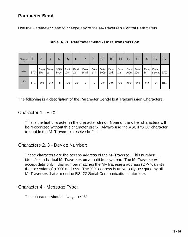
3 - 67
Parameter Send
Use the Parameter Send to change any of the M–Traverse's Control Parameters.
Table 3-38 Parameter Send - Host Transmission
1 2 3 4 5 6 7 8 9 10 11 12 13 14 15 16
Dev# Dev# MSG Par# Par# Data Data Data Data Data Data Data Data Data STX 10s 1s Type 10s 1s 10mil 1mil 100th 10th 1th 100s 10s 1s Format ETX
STX 0-9 0-9 3 0-9 0-9 0 0 0-9 0-9 0-9 0-9 0-9 0-9 0-; ETX
Character #
DESC
ASCII
The following is a description of the Parameter Send-Host Transmission Characters.
Character 1 - STX:
This is the first character in the character string. None of the other characters willbe recognized without this character prefix. Always use the ASCII “STX” characterto enable the M–Traverse's receive buffer.
Characters 2, 3 - Device Number:
These characters are the access address of the M–Traverse. This numberidentifies individual M–Traverses on a multidrop system. The M–Traverse willaccept data only if this number matches the M–Traverse's address (CP-70), withthe exception of a “00” address. The “00” address is universally accepted by allM–Traverses that are on the RS422 Serial Communications Interface.
Character 4 - Message Type:
This character should always be “3”.

3 - 68
Character 5, 6 - Parameter Number:
These characters identify the Control Parameter that you want to change(i.e., “16” = CP-16).
Characters 7 through 14 - DATA:
These characters transmit the new value for a Control Parameter that you want tochange. The Data must be within the range specified in Appendix E. Characters 7and 8 should always be "0" and are only used with the data inquiry response.
Character 15 - Data Format:
Character 15 indicates the decimal location and polarity of the data that wastransmitted in characters 7 through 14.
Use the following codes to indicate decimal location and polarity:
Code Format0 +XXXXXX1 +XXXXX.X2 +XXXX.XX3 +XXX.XXX4 +XX.XXXX5 +X.XXXXX6 -XXXXXX.7 -XXXXX.X8 -XXXX.XX9 -XXX.XXX: -XX.XXXX; -X.XXXXX.
Character 16 - ETX:
Always use the ASCII “ETX” character to terminate the record.
Example of Parameter Send:
A new Acceleration Time of 52.3 seconds is sent to the M–Traverse at address 4.
ASCII character string: “STX0436000005230ETX”
Note: The character string has no spaces between the characters.

3 - 69
Table 3-39 Parameter Send - M–Traverse Response
1 2 3 4 5 6 7 8 9 10 11 12 13 14 15 16
Dev# Dev# Error Par# Par# Data Data Data Data Data Data Data Data Data STX 10s 1s Code 10s 1s 10mil 1mil 100th 10th 1th 100s 10s 1s Format ETX
STX 0-9 0-9 @— 0-9 0-9 0-9 0-9 0-9 0-9 0 -9 0-9 0-9 0-9 0-; ETX
Character #
DESC
ASCII
The following is a description of the Parameter Send-M–Traverse Response Characters.
Character 1 - STX:
This is the first character in the character string.
Characters 2, 3 - Device Number:
This is the two character access address for the M–Traverse.
Character 4 - Error Code:
If there are errors in the transmission that the M–Traverse receives from the hostcomputer, the Error Code will display them. Use Table 3-42 to convert the ASCIIcode to binary. Then the binary code can be decoded as follows:
Bit 7 Always “0”.Bit 6 Always “1”.Bit 5 Always “0”.Bit 4 1 = Control Mask Error / Lockout during Run state.Bit 3 1 = Minimum / Maximum Error (out of range).Bit 2 1 = Data Error (invalid data).Bit 1 1 = Parameter Error (invalid parameter or message type).Bit 0 1 = Transmit Error (parity, framing, overrun, no STX or no ETX).
Note: The M–Traverse will only accept data if there are no errors. The ASCII errorcode “@” (Binary code “1000000”) indicates that the Host Transmission con-tains no errors. Also see MV-74 for the ASCII Error Code for the last ResponseMessage.

3 - 70
Characters 5,6 - Parameter Number:
The Control Parameter Code is sent back to the host computer from theM–Traverse.
Characters 7 through 14 - DATA:
The Control Parameter Data is sent back to the host computer from theM–Traverse.
Character 15 - Data Format:
The Data Format is sent back to the host computer from the M–Traverse.
Character 16 - ETX:
The return message is always terminated with the ASCII “ETX” character.
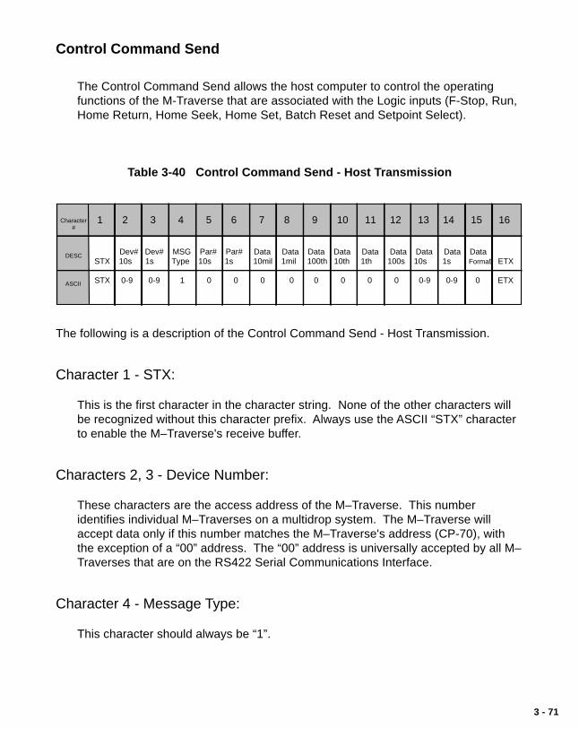
3 - 71
Control Command Send
The Control Command Send allows the host computer to control the operatingfunctions of the M-Traverse that are associated with the Logic inputs (F-Stop, Run,Home Return, Home Seek, Home Set, Batch Reset and Setpoint Select).
Table 3-40 Control Command Send - Host Transmission
1 2 3 4 5 6 7 8 9 10 11 12 13 14 15 16
Dev# Dev# MSG Par# Par# Data Data Data Data Data Data Data Data Data STX 10s 1s Type 10s 1s 10mil 1mil 100th 10th 1th 100s 10s 1s Format ETX
STX 0-9 0-9 1 0 0 0 0 0 0 0 0 0-9 0-9 0 ETX
Character #
DESC
ASCII
The following is a description of the Control Command Send - Host Transmission.
Character 1 - STX:
This is the first character in the character string. None of the other characters willbe recognized without this character prefix. Always use the ASCII “STX” characterto enable the M–Traverse's receive buffer.
Characters 2, 3 - Device Number:
These characters are the access address of the M–Traverse. This numberidentifies individual M–Traverses on a multidrop system. The M–Traverse willaccept data only if this number matches the M–Traverse's address (CP-70), withthe exception of a “00” address. The “00” address is universally accepted by all M–Traverses that are on the RS422 Serial Communications Interface.
Character 4 - Message Type:
This character should always be “1”.

3 - 72
Characters 5,6 - Parameter Number:
These characters should always be “0”.
Characters 7 through 12 - DATA:
These characters should always be “0”.
Characters 13,14- DATA:
01 F-Stop02 Not in Use03 Run04 Home Return05 Home Seek06 Home Set07 Batch Reset08 Setpoint Select 109 Setpoint Select 210 Setpoint Select 311 Setpoint Select 412 Not in Use13 Not in Use14 Not in Use15 Not in Use
Character 15 - Data Format:
This character should always be “0”.
Character 16 - ETX:
Always use the ASCII “ETX” character to terminate the character string.

3 - 73
Table 3-41 Control Command Send - M–Traverse Response
1 2 3 4 5 6 7 8 9 10 11 12 13 14 15 16
Dev# Dev# Error Par# Par# Data Data Data Data Data Data Data Data Data STX 10s 1s Code 10s 1s 10mil 1mil 100th 10th 1th 100s 10s 1s Format ETX
STX 0-9 0-9 @— 0 0 0 0 0 0 0 0 0-9 0-9 0 ETX
Character #
DESC
ASCII
The following is a description of the Control Command Send-M–Traverse Response Characters.
Character 1 - STX:
This is the first character in the character string.
Characters 2, 3 - Device Number:
This is the two character access address for the M–Traverse.
Character 4 - Error Code:
If there are errors in the transmission that the M–Traverse receives from the hostcomputer, the Error Code will display them. Use Table 3-42 to convert the ASCIIcode to binary. Then, the binary code can be decoded as follows:
Bit 7 Always “0”.Bit 6 Always “1”.Bit 5 Always “0”.Bit 4 1 = Control Mask Error / Lockout during Run state.Bit 3 1 = Minimum / Maximum Error (out of range).Bit 2 1 = Data Error (invalid data).Bit 1 1 = Parameter Error (invalid parameter or message type).Bit 0 1 = Transmit Error (parity, framing, overrun, no STX or no ETX).
Note: The M–Traverse will only accept data if there are no errors. The ASCIIerror code “@” (Binary code “1000000”) indicates that the Host Transmissioncontains no errors. Also see MV-74 for the ASCII Error Code for the lastResponse Message.

3 - 74
Characters 5,6 - Parameter Number:
These characters will always be “0”.
Characters 7 through 12 - DATA:
These characters will always be “0”.
Characters 13,14 - DATA:
The command function of the message that was received, is returned.
Character 15 - Data Format:
This character will always be “0”.
Character 16 - ETX:
The return message is always terminated with the ASCII “ETX” character.

3 - 75
Data Inquiry
Use the Data Inquiry to request the current value for Parameters (i.e., ControlParameters or Monitor Variables).
Table 3-42 Data Inquiry - Host Transmission
1 2 3 4 5 6 7 8 9 10 11 12 13 14 15 16
Dev# Dev# MSG Par# Par# Data Data Data Data Data Data Data Data Data STX 10s 1s Type 10s 1s 10mil 1mil 100th 10th 1th 100s 10s 1s Format ETX
STX 0-9 0-9 2 0-9 0-9 0 0 0 0 0 0 0 0 0 ETX
Character #
DESC
ASCII
The following is a description of the Data Inquiry - Host Transmission Characters.
Character 1 - STX:
This is the first character in the character string. None of the other characters willbe recognized without this character prefix. Always use the ASCII “STX” characterto enable the M–Traverse's receive buffer.
Characters 2, 3 - Device Number:
These characters are the access address of the M–Traverse. This numberidentifies individual M–Traverses on a multidrop system. The M–Traverse willaccept data only if this number matches the M–Traverse's address (CP-70), withthe exception of a “00” address. The “00” address is universally accepted by allM–Traverses that are on the RS422 Serial Communications Interface.
Character 4 - Message Type:
This character should always be “2”.

3 - 76
Characters 5,6 - Parameter Number:
This is the Control Parameter Code (i.e., enter “16” for CP–16).
Characters 7 through 14 - DATA:
These characters should always be “0”.
Character 15 - Data Format:
This character should always be “0”.
Character 16 - ETX:
Always use the ASCII “ETX” character to terminate the character string.

3 - 77
Table 3-43 Data Inquiry - M–Traverse Response
1 2 3 4 5 6 7 8 9 10 11 12 13 14 15 16
Dev# Dev# Error Par# Par# Data Data Data Data Data Data Data Data Data STX 10s 1s Code 10s 1s 10mil 1mil 100th 10th 1th 100s 10s 1s Format ETX
STX 0-9 0-9 @— 0-9 0-9 0-9 0-9 0-9 0-9 0 -9 0-9 0-9 0-9 0-; ETX
Character #
DESC
ASCII
The following is a description of the Data Inquiry-M–Traverse Response Characters.
Character 1 - STX:
This is the first character in the character string.
Characters 2, 3 Device Number:
This is the two character access address for the M–Traverse.
Character 4 -Error Code:
If there are errors in the transmission that the M–Traverse receives from the hostcomputer, the Error Code will display them. Use Table 3-42 to convert the ASCIIcode to binary. Then the binary code can be decoded as follows:
Bit 7 Always “0”.Bit 6 Always “1”.Bit 5 Always “0”.Bit 4 1 = Control Mask Error / Lockout during Run state.Bit 3 1 = Minimum / Maximum Error (out of range).Bit 2 1 = Data Error (invalid data).Bit 1 1 = Parameter Error (invalid parameter or message type).Bit 0 1 = Transmit Error (parity, framing, overrun, no STX or no ETX).
Note: The M–Traverse will only accept data if there are no errors. The ASCII errorcode “@” (Binary code “1000000”) indicates that the Host Transmissioncontains no errors. Also see MV-74 for the ASCII Error Code for the lastResponse Message.

3 - 78
Characters 5,6 - Parameter Number:
The Control Parameter Code is sent back to the host computer from theM–Traverse.
Characters 7 through 14 - DATA:
The Control Parameter or Monitor Variable data that was requested is sent back tothe host computer from the M–Traverse.
For an interpretation of the MV-50 through MV-56 data, refer toTable 3-43. For the ASCII to binary conversion, refer to Table 3-42.
Character 15 - Data Format:
Character 15 indicates the decimal location and polarity of the data that wastransmitted in characters 7 through 14.
Use the following codes to indicate decimal location and polarity:
Code Format0 +XXXXXX1 +XXXXX.X2 +XXXX.XX3 +XXX.XXX4 +XX.XXXX5 +X.XXXXX6 -XXXXXX.7 -XXXXX.X8 -XXXX.XX9 -XXX.XXX: -XX.XXXX; -X.XXXXX.
Character 16 - ETX:
The return message is always terminated with the ASCII “ETX” character.

3 - 79
Table 3-44 ASCII to Binary
ASCII Binary ASCII BinaryBit 7 Bit 1 Bit 7 Bit 1
@ 1000000 ' 1100000A 1000001 a 1100001B 1000010 b 1100010C 1000011 c 1100011D 1000100 d 1100100E 1000101 e 1100101F 1000110 f 1100110G 1000111 g 1100111H 1001000 h 1101000I 1001001 i 1101001J 1001010 j 1101010K 1001011 k 1101011L 1001100 l 1101100M 1001101 m 1101101N 1001110 n 1101110O 1001111 o 1101111P 1010000 p 1110000Q 1010001 q 1110001R 1010010 r 1110010S 1010011 s 1110011T 1010100 t 1110100U 1010101 u 1110101V 1010110 v 1110110W 1010111 w 1110111X 1011000 x 1111000Y 1011001 y 1111001Z 1011010 z 1111010[ 1011011 { 1111011\ 1011100 | 1111100] 1011101 } 1111101^ 1011110 ~ 1111110– 1011111 DEL 1111111
ASCII Binary ASCII BinaryBit 7 Bit 1 Bit 7 Bit 1
NUL 0000000 SP 0100000SOH 0000001 ! 0100001STX 0000010 " 0100010ETX 0000011 # 0100011EOT 0000100 $ 0100100ENQ 0000101 % 0100101ACK 0000110 & 0100110BEL 0000111 ' 0100111BS 0001000 ( 0101000HT 0001001 ) 0101001LF 0001010 * 0101010VT 0001011 + 0101011FF 0001100 , 0101100CR 0001101 - 0101101SO 0001110 . 0101110SI 0001111 / 0101111DLE 0010000 0 0110000DC1 0010001 1 0110001DC2 0010010 2 0110010DC3 0010011 3 0110011DC4 0010100 4 0110100NAK 0010101 5 0110101SYN 0010110 6 0110110ETB 0010111 7 0110111CAN 0011000 8 0111000EM 0011001 9 0111001SUB 0011010 : 0111010ESC 0011011 ; 0111011FS 0011100 < 0111100GS 0011101 = 0111101RS 0011110 > 0111110US 0011111 ? 0111111

3 - 80
Tabl
e 3-
45
Bin
ary
Mon
itor
Par
amet
ers
Set
ptS
elec
t BC
lose
d
MV
-51
M
V-5
2
MV
-53
M
V-5
4
MV
-55
M
V-5
6
MV
-57
Hom
eis
Def
ined
0
1
0
1
0
1
0
1
0
1
0
1
0
1
Mon
itor
Par
amet
ers
and
Cor
resp
ondi
ng B
inar
y N
umbe
rs
Jog
Act
ive
Hom
eS
eek
Inac
tive
Run
Ope
n
For
war
dLi
mit
Ope
n
For
war
dLi
mit
Clo
sed
Rev
erse
Lim
itO
pen
Rev
erse
Lim
itC
lose
d
Not in Use
Hom
eS
ync
Clo
sed
Set
ptS
elec
t AO
pen
Not in Use
Ala
rmIn
activ
eA
larm
Act
ive
Hom
eS
etO
pen
Hom
eS
etC
lose
d
Hom
eS
eek
Clo
sed
Hom
eS
eek
Ope
n
Hom
eR
etur
nO
pen
Hom
eR
etur
nC
lose
d
Bat
chR
eset
Ope
n
Bat
chR
eset
Clo
sed
Not in Use
No
Ala
rm
For
war
d/R
ever
seLi
mit
Hig
hS
peed
Ala
rm
Hom
eN
ot
Def
ined
Hom
e R
etur
nIn
activ
e
Hom
eS
eek
Act
ive
Run
Act
ive
Hom
eR
etur
nA
ctiv
e
Jog
Inac
tive
Jog
Clo
sed
Jog
For
war
d/R
ever
seC
lose
d
Run
Clo
sed
Wai
tC
lose
d
Jog
Ope
n
Jog
For
war
d/R
ever
seO
pen
Wai
tO
pen
Driv
e E
nabl
eA
ctiv
e
Driv
eE
nabl
eIn
activ
e
Bat
chD
one
Act
ive
Bat
ch
Don
eIn
activ
e
Not in Use
Not in Use
Out
BA
ctiv
eO
ut B
Inac
tive
Pro
file
Dire
ctio
nR
ever
se
Pro
file
Dire
ctio
nF
orw
ard
Not in UseNot in Use
Not in Use
Not in Use
Not in Use
At-
Hom
eN
ot
At-
Hom
eF
-Sto
pIn
activ
eF
-Sto
pA
ctiv
eF
-Sto
pC
lose
dF
-Sto
pO
pen
Set
ptS
elec
t AC
lose
d
Set
ptS
elec
t BO
pen
Not in Use
Not in Use
Wai
tA
ctiv
eK
eypa
dLo
ckou
tC
lose
d
Key
pad
Lock
out
Ope
n
Not in Use
Not in Use
Not in Use
At-
Hom
eA
ctiv
eA
t-H
ome
Inac
tive
Out
AA
ctiv
eO
ut A
Inac
tive
Not in Use Not in Use
Not in Use Not in Use
Not in Use
Not in Use
Not in Use
Not in Use
Not in Use
Not in Use
Not in Use
Not in Use
Not in Use
Not in Use
Not in Use
Not in Use
Not in Use Not in Use
Not in Use
Not in Use
Not in Use
Not in Use
Not in Use
Not in Use
Not in Use
Not in Use
Not in Use
Not in Use Not in Use
Not in Use
Not in Use
Not in
Use
Not in Use
Run
Inac
tive
Hom
eS
ync
Ope
n
No
Lim
it
Wai
tIn
activ
e
Pos
ition
on
Bin
ary
Cod
e S
trin
g
0 1 2 3 4 5 6 7

4 - 1
Troubleshooting
DiagnosticsTroubleshootingEPROM Chip Replacement

4 - 2

4 - 3
DIAGNOSTICSThis section describes how to use the diagnostic routines to verify that the M–Traverseis operating properly as well as to identify any M–Traverse problems. The diagnosticroutines are run independently, with the M–Traverse temporarily disconnected fromyour system. Begin diagnostics with the Clear/4 test, then run tests 1-10. Use the“Status” key to increment through the tests and the “Tach” key to decrement through thetests.
If you need to verify the integrity of the M–Traverse relative to your system, refer to theTroubleshooting: Troubleshooting section. If any of theses tests fail or if the informationin this section does not solve your problem, consult:
Contrex Technical Support (763) 424-7800 or (800) 342-4411
Clear/4 Test - To Begin Diagnostic Testing
To begin diagnostic testing, turn the M–Traverse off and disconnect it fromyour system.
Turn the power on the M–Traverse while simultaneously pressing “Clear”and “4” on the keypad.
The M–Traverse defaults to Micro Controller Register File Test #1. The“HELP” diagnostic indicator is visible on the left side of the upper LEDdisplay and the number “1” (indicating the test number) is visible on theright side of the upper LED display. If you do not see “HELP” and thenumber “1,” you are not in diagnostics. The example below shows the“HELP” diagnostic indicator and test number “1” on the LED display.
Help DiagnosticIndicator Test Number

4 - 4
Micro Controller Register File Test #1 - ------To Test the Micro Controller
Clear/4 automatically defaults to the Micro Controller Register File Test#1. “HELP” and the number “1” are visible in the upper LED display. Ifthe panel covering the lower LEDs is closed, open it now.
Press “Enter” to start the test.
If Micro Controller Register File is good, then “PP” is visible in the lowerLED display.
If Micro Controller Register File fails, an “EE” is visible in the lower LEDdisplay.
The test stops immediately if a failure is detected.
Press “Clear ” to remove the “PP” and continue to the next test.Press “Code Select” only if you want to exit diagnostics.
RAM Test #2 - ------To Test Random Access Memory
To enter this test, press the “Status” key to increment (or the “Tach” keyto decrement) until the number “2” is visible on the right side of theupper LED display.
Press “Enter” to start the test.
If RAM is good, then “PP” is visible in the lower LED display.
If RAM fails, an “EE” is visible in the lower LED display.The test stops immediately if a failure is detected.
Press “Clear ” to remove the “PP” and continue to the next test.Press “Code Select” only if you want to exit diagnostics.

4 - 5
EPROM Test #3 - ------To Test Programmable Read Only Memory
To enter this test, press the “Status” key to increment (or the “Tach” keyto decrement) until the number “3” is visible on the right side of theupper LED display.
Press “Enter” to start the test.
If EPROM is good, then “PP” is visible in the lower LED display.
If EPROM fails, an “EE” is visible in the lower LED display.
Press “Clear ” to remove the “PP” and continue to the next test.Press “Code Select” only if you want to exit diagnostics.
Display Test #4- To Test Upper and Lower LED Display Panel Segments
To enter this test, press the “Status” key to increment (or the “Tach” keyto decrement) until the number “4” is visible on the right side of theupper LED display.
Press “Enter” to start the test.
NOTE: The M–Traverse will quickly run through all of the display variations.Watch each of the display variations carefully for missing segments. Forexample, a nine with missing segments could look like a seven. The M–Traverse will display the following:
Upper LED Display Lower LED Display
0.0.0.0.0.0. 0.0.1.1. 1.1.1.1. 1.12.2.2.2.2.2. 2.2.3.3.3.3.3.3. 3.3.4.4.4.4.4.4. 4.4.5.5.5.5.5.5. 5.5.6.6.6.6.6.6. 6.6.7.7.7.7.7.7. 7.7.8.8.8.8.8.8. 8.8.9.9.9.9.9.9. 9.9.–.–.–.–.–.–. –.–.E.E.E.E.E.E. E.E.H.H.H.H.H.H. H.H.L.L.L.L.L.L. L.L.P.P.P.P.P.P. P.P.

4 - 6
. . . . . . . .0.0.0.0.0.0. 0.0.1.1.1.1.1.1. 1.1.2.2.2.2.2.2. 2.2.3.3.3.3.3.3. 3.3.4.4.4.4.4.4. 4.4.5.5.5.5.5.5. 5.5.6.6.6.6.6.6. 6.6.7.7.7.7.7.7. 7.7.8.8.8.8.8.8. 8.89.9.9.9.9.9. 9.9.A.A.A.A.A.A. A.A.b.b.b.b.b.b. b.b.C.C.C.C.C.C. C.C.d.d.d.d.d.d. d.d.E.E.E.E.E.E. E.E.F.F.F.F.F.F. F.F.
The lower LED display is blank and the upper LED display defaultsback to “Help” and the number “4” after the M–Traverse has completedthe display variations.
The M–Traverse automatically exits the test - go to the next test.Press “Code Select” only if you want to exit diagnostics.
Annunciator Test #5- To Test the Discrete LED Indicator Display
To enter this test, press the “Status” key to increment (or the “Tach” keyto decrement) until the number “5” is visible on the right side of theupper LED display.
Press “Enter” to start the test.
If they are functioning properly, the discrete LED indicator displays willilluminate in this order:
Code SelectStatusTachSetpointBatch CountRunControl EnableLead SyncAt-HomeAlarm
The M–Traverse automatically exits the test - go to the next test.Press “Code Select” only if you want to exit diagnostics.
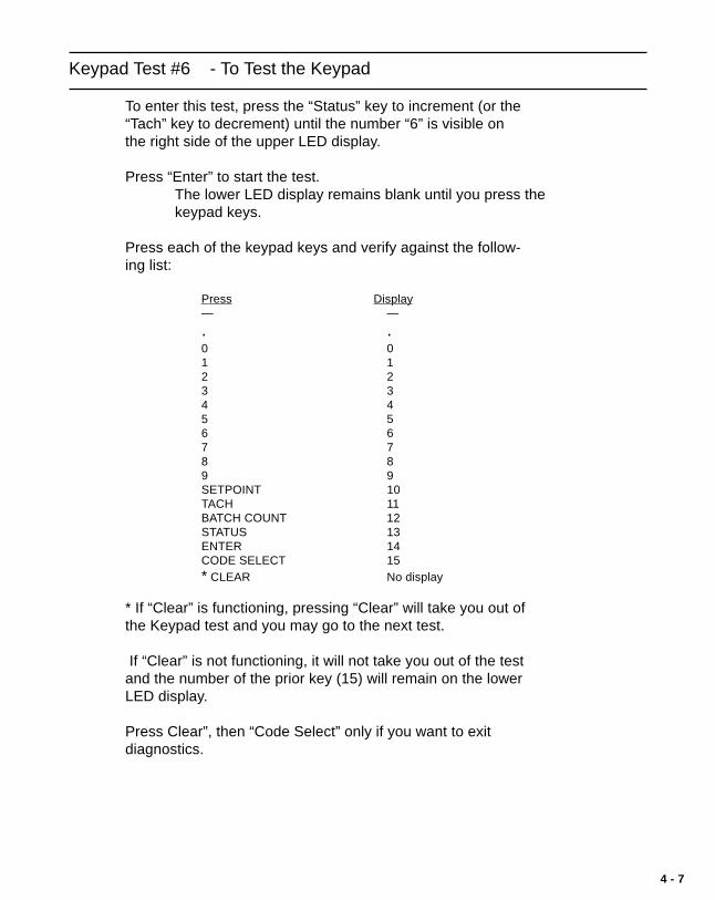
4 - 7
Keypad Test #6 - To Test the Keypad
To enter this test, press the “Status” key to increment (or the“Tach” key to decrement) until the number “6” is visible onthe right side of the upper LED display.
Press “Enter” to start the test.The lower LED display remains blank until you press thekeypad keys.
Press each of the keypad keys and verify against the follow-ing list:
Press Display— —
. .0 01 12 23 34 45 56 67 78 89 9SETPOINT 10TACH 11BATCH COUNT 12STATUS 13ENTER 14CODE SELECT 15* CLEAR No display
* If “Clear” is functioning, pressing “Clear” will take you out ofthe Keypad test and you may go to the next test.
If “Clear” is not functioning, it will not take you out of the testand the number of the prior key (15) will remain on the lowerLED display.
Press Clear”, then “Code Select” only if you want to exitdiagnostics.

4 - 8
Input Test #7 - To Test the Discrete Inputs
To enter this test, press the “Status” key to increment (or the “Tach” keyto decrement) until the number “7” is visible on the right side of theupper LED display.
Press “Enter” to start the test.
The lower LED display will remain blank unless an input has beenshorted to common. If an input has been shorted, it's number willdisplay. For example, if the number four appears in the display, then F–Stop has been shorted. To test an input, short that input and open all ofthe other inputs.
Input Closure Display
NOT USED (J3-10) 10HOME SYNC (J3-12) 11SETPOINT SELECT A (J3-13) 12SETPOINT SELECT B (J3-15) 13HOME SET (J3-16) 14HOME SEEK (J4-2) 15HOME RETURN (J4-3) 16BATCH RESET (J4-5) 17RUN (J4-6) 02WAIT (J4-8) 03F-STOP (J4-9) 04KEYLOCK (J4-11) 05FWD LIMIT (J4-12) 06REV LIMIT (J4-14) 07JOG FWD/REV (J4-15) 01JOG (J4-17) 00
Press “Clear” to exit the test.Press “Code Select” only if you want to exit diagnostics.

4 - 9
Output Test #8 - To Test the Discrete Outputs
To enter this test, press the “Status” key to increment (or the “Tach” keyto decrement) until the number “8” is visible on the right side of theupper LED display.
Only the “Help” diagnostic indicator and the number “8” will be visibleon the upper LED display during this test. To run this test, connect theoutputs to a pull up resistor and either a meter or LED, or connect theoutputs to a relay and either lights or sound.
Press “Enter” to start the test.
Press keys 1 - 7 to activate the outputs.
Press To Activate
1 Drive Enable2 Batch Done3 Alarm4 Profile Dir.5 At-Home6 Output A7 Output B
Press “Clear” to exit the test.Press “Code Select” only if you want to exit diagnostics.
Speed Command Out Test #9- To Test the Speed Command Out
To enter this test, press the “Status” key to increment (or the “Tach” keyto decrement) until the number “9” is visible on the right side of theupper LED display.
Use an oscilloscope to view Speed Command Analog Output (J1 Pin 9).The output should ramp from +10 volts to –10 volts, then back to +10volts.
Press “Enter” to start the test.
Press “Clear” to exit the test.Press “Code Select” only if you want to exit diagnostics.

4 - 10
Serial Input Test #10- To Test the Serial Input
To enter this test, press the “Status” key to increment (or the “Tach” keyto decrement) until the number 10” is visible on the right side of theupper LED display.
Jumper J1 Pin 4 to J1 Pin 2Jumper J1 Pin 5 to J1 Pin 3
Press “Enter” to start the test.
If the Serial Input is good, then “PP” is visible in the lower LED display.
If the Serial Input fails, one or all of the following will display briefly inthe lower LED display:
Failure Lower LED Display
300 baud failure 032400 baud failure 249600 baud failure 96
If any failures have occurred, an “EE” will display briefly in the lowerLED display when the test has been completed.
The M–Traverse automatically exits the test.Press “Code Select” only if you want to exit diagnostics.

4 - 11
In addition to the diagnostic tests 1-10 that you can perform, the M–Traverseautomatically performs two power up diagnostic routines during every power up.
RAM TEST - Random Access Memory
The M–Traverse performs a pattern read/write test on RAM.
If RAM fails, error code “-----5” appears in the upper LED display.The test will stop if a failure is detected.Press “Clear ” to continue the test.
IF the RAM is good, the M–Traverse will begin the PROM test.
PROM TEST - Programmable Read Only Memory
The M–Traverse performs a checksum comparison on the PROM.
If the test fails, error code “-----3” appears in the upper LED display.The test stops if a failure is detected.Press “Clear”.
If PROM is good, exit is automatic. The M–Traverse will begin the initializationroutines and normal operation.

4 - 12
In addition to the diagnostic and power up tests, M–Traverse has automatic indicatorsthat alert you when there is a power line failure or EMI noise.
Power Failure
If the AC power line voltage drops below the level that is specified for the M-Traverse,then “- - - - - 1” will appear in the upper LED display. Check the power line for ACvoltage integrity. Use MV-59 to monitor line notching.
CPU Watchdog Failure
If a CPU watchdog failure occurs, then “- - - - - 2” will appear in the upper LED display.This failure is generally the result of EMI or high frequency noise on the power or thesignal lines. To prevent these failures:
Ground the chassis and AC power properly.Only one end of the shield wire in a shielded cable should be attached to
earth ground.Install a power line filter on the AC line if you suspect there may be AC line
noise.Isolate the internal signal common (J3 Pin 4) and chassis ground (J2 Pin 1).Install ARC suppressors on any relay and contactors that are in close
proximity to the M-Traverse.Keep all signal wires isolated from AC power wires.
Because “- - - - - 2” indicates that the CPU has malfunctioned, it is important torestore the M-Traverse default memory locations. Run the Clear 7 Power Upprocedure and the M-Traverse will restore the factory default settings and it will alsoperform the power up routine. To run the Clear 7 Power Up procedure:
Record the Control Parameters that are unique to your system.Turn the power to the M-Traverse off.Turn the power to the M–Traverse on, while simultaneously pressing “Clear”
and “7” on the keypad.The M-Traverse restores the factory default settings and then performs the
power up routine.Reenter the Control Parameters that are unique to your system.

4 - 13
TROUBLESHOOTING
This section contains four troubleshooting flowcharts to help you resolve four possiblesystem operating problems. The four scenarios that are addressed by the flowchartsare:
Motor Does Not StopMotor Does Not RunMotor Runs at Wrong SpeedMotor Runs Unstable
If you need to verify the integrity of the M–Traverse independently, refer to theTroubleshooting: Diagnostics section. If the information in this section does not solveyour problem, consult:
Contrex Technical Support (763) 424-8700 or (800) 342-4411

4 - 14
Figure 4-1 Motor Does Not Stop Flowchart
Yes
Motor Does Not Stop
MV-52010000
(F–Stop)
J3, Pin 6 isshorted to common ?
Remove wire at J1, Pin 9Measure voltage with respect to J1, Pin 10
Voltage = “0”
MV-52000010(Run)
MV-52000001 (Jog)
Wiring toMotor Driveis correct ?
Consult TechSupport
J4, Pin 17 isshorted to common ?
Open J3, Pin 6
Problem Corrected ?
NO
Yes
NO
NO
NO
Yes
NO Yes
NO
NO
Yes
Yes
Yes
DriveCalibrationis correct ?
NO
NO NO
NO
NO
NO
NOYes
Yes
Yes
Yes
NO NO
MV-52000100
(Home Return)
MV-52001000
(Home Seek)
J4, Pin 3 isshorted to common ?
J4, Pin 2 isshorted to common ?
Open J4, Pin 17
Open J4, Pin 3
Open J4, Pin 2
Yes

4 - 15
Figure 4-2 Motor Does Not Run Flowchart
CP-14 = 1(Follower)
CP-14 = 2(Direct)
Yes
Motor Does Not Run
Consult TechSupport
Problem Corrected ?
Yes
NO
NO
Setpoint is correct ?
NO
Enter CorrectSetpoint
Yes
MV-47 isZero ?
Check DriveWiring
CP-61 is correct ?
Yes
NO
NO
NO
Yes YesNO
NO
NO
J4, Pin 9 isshorted
to common ?
Yes
ProblemCorrected ?
NO
Consult TechSupport
Yes
NO
Yes
CP-61 is correct ?
Yes
NO
Enter CorrectJog Setpoint
Short J4,Pin 9
to common
NO
Yes
MV-52000001 (Jog)
MV-52000010(Run)
MV-52010000
(F–Stop)

4 - 16
Figure 4-3 Motor Runs at Wrong Speed Flowchart
CP-14 =1 (Follower)
CP-14 =2 (Direct)
Yes
Motor Runs at Wrong Speed
Consult TechSupport
Problem Corrected ?
YesNO
NO
Setpoint is correct ?
NO
Yes
Enter CorrectSetpoint
MP-48 isNegative ?
DecreaseMax Speed
IncreaseMax Speed
CP-61 is correct ?
Yes
NO
NO
NOYes RepeatCalibrationProcedure

4 - 17
Figure 4-4 Motor Runs Unstable Flowchart
Change CP-14 to “2”and Run in Direct Mode
Check DriveCalibration
NO
Motor Runs Unstable
Motor StillUnstable ?
NO
Yes
Consult TechSupport
Problem Corrected ?

4 - 18
Figure 4-5 EPROM Location
EpromLocation

4 - 19
EPROM CHIP REPLACEMENTThe EPROM (Erasable Programmable Read Only Memory) chip is the software for theM–Traverse. See Figure 4-5 for the EPROM's location on the CPU Board.
To replace the EPROM chip:
• Make a record of your current Control Parameter values; the replacementchip contains default values that will replace your current values when youperform the Clear/7 step.
• Turn off the power to the M–Traverse.
• Ground yourself - Static electricity can damage the CPU board and theEPROM chip.
• Remove the back panel.
• Pull out the CPU board.
• Locate the EPROM chip and note the orientation of the Pin 1 Indicator.
• Carefully pry the EPROM that is being replaced from the socket.
• Carefully install the replacement EPROM in the socket, using the Pin 1Indicator for correct placement. Be careful not to bend the EPROM pins.
NOTE: Incorrect placement can damage the EPROM.
• Replace the CPU board.
• Replace the back panel.
• Press “Clear” and “7” and apply power to the M–Traverse simultaneously.
• The M–Traverse restores the factory default settings and automaticallyperforms the Power Up diagnostic routines.
• Reenter your Code Parameters values.

4 - 20
—NOTES—

5 - 1
References
GlossaryAppendix A - M–Traverse SpecificationsAppendix B - FormulasAppendix C - Parameter Summary -
Numeric Quick ReferenceAppendix D - Control Parameter ReferenceAppendix E - Monitor Variable ReferenceAppendix F - Fax Cover SheetAppendix G - Wiring Diagram ExamplesAppendix H - Revision LogService PolicyWarrantyIndex

5 - 2

5 - 3
GLOSSARY
Acceleration/Deceleration See Appendix C; CP-60.
Accel/Decel Length See Appendix C; CP-09.
Alarm - High Speed See Appendix C; CP-23.
Alarm Status See Appendix C; MV-51.
At-Home Band See Appendix C; CP-30.
Batch Count See Appendix C; MV-89.
Batch Format See Appendix C; CP-26.
Batch Limit See Appendix C; CP-27.
Batch Preact Distance See Appendix C; CP-28.
Baud Rate See Appendix C; CP-71.
Calibration Calibration matches the analog output of the M-Traversewith the analog input of the motor drive.
Change Activation See Appendix C; CP-25.
Character Format See Appendix C; CP-72.
Closed loop A system that is controlled by manipulating the output basedon error (setpoint - feedback).
Closed Loop Compensation A mathematical term for a control algorithm that resolves(PI) Software the control error (feedback - setpoint) to zero.
Output = Kp X Error + KI ∫ Error dtPI represents “Proportional and Integral”.
Code Select Key This is the key that is used prior to entering a ParameterCode (either a Control Parameter or a Monitor Variable).
Control Command Send The Control Command Send allows the host computer tocontrol the operating functions of the M-Traverse that areassociated with the Discrete inputs (F-Stop, Run, Home
5 - 4
Return, Home Seek, Home Set, Batch Reset, and SetpointSelect).
Control Mask See Appendix C; CP-73.
Control Mode See Appendix C; CP-14.
Control Parameters Control Parameters allow you to enter data that is uniqueto your system (e.g., encoder resolution, Lead to Followerratios) and modify the M–Traverse for your specific needs(e.g., maximum RPMs, setpoints, acceleration/decelerationramp rates). There are Control Parameters for Directmode, the Follower mode, Jog, Tuning, and Output Con-trol. The M–Traverse comes factory pre-loaded with acomplete set of default Control Parameters.
Control State See Appendix C; MV-52.
Communications Error See Appendix C; MV-74.
DAC Output See Appendix C; MV-47.
Data Inquiry Use the Data Inquiry to request the current value forParameters (i.e., Control Parameters or Monitor Variables)in serial communications.
Dedicated Keys The “Setpoint ” , “Tach” , “Batch Count” and “Status” keysare shortcut keys that access the active Setpoint , Tach,Batch Count and Status variables directly, rather thanmanually entering the Code Parameter.
Device Address See Appendix C; CP-70.
Digital Motor Controller A precision motor controller that uses digital compensationtechnology.
Direct Analog Command See Appendix C; CP-62.
Direct Mode In the Direct mode of operation, the analog output from theM-Traverse that is connected to the motor drive can be setdirectly. Direct mode is an open-loop mode of operation.Scaling, Acceleration/Deceleration, and Closed LoopCompensation (PI) software are not involved in the Directmode. The Direct mode is used in conjunction with theRun and F-Stop controls

5 - 5
Discrete Inputs Setpoint Select A WaitSetpoint Select B F-StopHome Set Keypad LockoutHome Seek Forward LimitHome Return Reverse LimitBatch Reset Jog Forward/ReverseRun Jog
Discrete Inputs - Group A See Appendix C; MV-53.
Discrete Inputs - Group B See Appendix C; MV-54.
Discrete Inputs - Group C See Appendix C; MV-55.
Discrete Outputs - Group A See Appendix C; MV-56.
Discrete Outputs - Group B See Appendix C; MV-57.
Dwell See Appendix C; CP-10.
Edge/Center Based Profile See Appendix C; CP-24.
Engineering Units (E.U.) Engineering units are the units of measure that you selectfor your setpoint scaling (e.g., inches, feet or centimeters).
EPROM Chip The EPROM (Erasable Programmable Read OnlyMemory) chip is the software for the M–Traverse.
F–Stop The F–Stop discrete input brings the M–Traverse's speedcommand (analog output) to an immediate Zero. F–Stophas priority over the other operating states.
Feedback Frequency See Appendix C; MV-42.
Follower Engineering Units See Appendix C; MV-45.
Follower Job Size See Appendix C; MV-81.
Follower Lines Per E.U. See Appendix C; CP-17.
Follower Mode A complex multi-drive system. This is the M-Traverse'sprimary mode of operation. The M–Traverse compares theprofile ratio or percentage of the Follower sensor shaftfeedback and Lead sensor shaft to calculate any positionerror. When the M–Traverse finds speed error, the controlalgorithm adjusts the motor drive's Speed Commandanalog output and reduces the error to zero.

5 - 6
Follower Position See Appendix C; MV-44.
Follower Profile Length See Appendix C; MV-84.
Fwd/Rev Limit Polarity See Appendix C; CP-36.
Gain See Appendix C; CP-65.
Hardwired Inputs that are wire shorted rather than using push buttonsor switches.
Home Offset See Appendix C; CP-31.
Home Sync Polarity See Appendix C; CP-35.
Input Monitoring Lead Frequency (MV-41)Feedback Frequency (MV-42)Discrete inputs, Group A (MV-53)Discrete Inputs, Group B (MV-54)Discrete Inputs, Group C (MV-55)
Inputs Input Power (J2 pins 1, 2,3)Lead Frequency (J3 pins 3, 4, 5)Feedback Frequency (J3 pins 7, 8, 9)Home Sync (J3 pins 11, 12)Setpoint Select A (J3 pins 13, 14)Setpoint Select B (J3 pins 14, 15)Home Set (J4 pins 14, 16)Home Seek (J4 pins 1, 2)Home Return (J4 pins 3, 4)Batch Reset (J4 pins 4, 5)Run (J4 pins 6, 7)Wait (J4 pins 7, 8)F-Stop (J4 pins 9, 10)Keypad Lockout (J4 pins 10, 11)Forward Limit (J4 pins 12, 13)Reverse Limit (J4 pins 13, 14)Jog Forward/Reverse (J4 pins 15, 16)Jog (J4 pins 16, 17)
Integral See Appendix C; CP-66.
Invalid Profile See Appendix C; MV-58.Jog Jog is used in conjunction with Home Set and Home Seek

5 - 7
to move the Follower mechanism to “Home”. Jog can alsobe used when you need brief bursts of speed to align theFollower mechanism. When you activate Jog, the RPMsincrease at the acceleration rate that you specified inAcceleration/Deceleration (CP-60) until the Jog Setpoint(CP-61) is achieved. When Jog is terminated, the RPMsreturn to zero immediately. The Jog direction is deter-mined by the Jog Forward/Reverse Input (J4, pins 15,16),which controls the direction of the Speed CommandOutput. The Drive Enable discrete output is active duringthe Jog mode.
Jog Setpoint See Appendix C; CP-61.
Keypad Error See Appendix C; MV-50.
Lead Frequency See Appendix C; MV-41.
Lead Job Size See Appendix C; MV-80.
Lead Position See Appendix C; MV-43.
Lead PPR Reel See Appendix C; CP-16.
LED Display The two digit Parameter Code is displayed in the lowerLED Display. The Parameter Code's value is displayed inthe upper LED display. This value can be up to six digits.
Line Notch Counter See Appendix C; MV-59.
Max RPM Follower See Appendix C; CP-19.
Mode of Operation The method used to operate your system, for exampleDirect mode or Follower mode.
Monitor Variables Monitor Variables (MVs) monitor the performance of theM–Traverse and the system which the M–Traverse iscontrolling. Monitor Variables also confirm the wiring, thetuning and assist with troubleshooting. MVs can beaccessed at any time during the M–Traverse's operation,including during Run, Jog and F–Stop. There are fourcategories of Monitor Variables: Input Monitoring, OutputMonitoring, Performance Monitoring and Status Monitor-ing.
Numeric Keys Use the numeric keys to enter a Parameter Code for either
5 - 8
a Control Parameter (CP) or a Monitor Variable (MV) ORto enter a value for a Control Parameter. Use the “Enter”key after each entry. Use the “Clear” key to delete yourentry.
Open Loop A system that is controlled only by inputs without feedback.
Operating State The systems status, such as Run, F–Stop, or Jog, within amode of operation.
Output Monitoring DAC Output (MV-47)Trim Output (MV-48)Discrete Outputs - Group A (MV-56)Discrete Outputs - Group B (MV-57)
Output A Direction See Appendix C; CP-91.
Output A Polarity See Appendix C; CP-92.
Output A Segment See Appendix C; CP-90.
Output B Direction See Appendix C; CP-94.
Output B Polarity See Appendix C; CP-95.
Output B Segment See Appendix C; CP-93.
Outputs Speed Command Out (J1 pins 8, 9, 10, 11)Drive Enable (J1 pin 13)Batch Done (J1 pin 14)Alarm (J1 pin 15)Profile Direction (J1 pin 16)At-Home (J1 pin 17)Output A (J1 pin 18)Output B (J1 pin 19)Auxiliary DC Power (J3 pin 1, 2)
Parameters Parameters are divided into two classifications; ControlParameters (CP) and Monitor Variables (MV).
Parameter Code The numbered code that represents a Parameter.
Parameter Send Use the Parameter Send to change any of the M–Traverse's Control Parameters in Serial Communications.
Parameter Value Default parameter values are pre-loaded in the factory,

5 - 9
however, you can modify Control Parameter values withoperational data that is unique to your system.
Performance Monitoring TachLead PositionFollower PositionFollower Engineering UnitsProduct RatePosition Error
Position Error See Appendix C; MV-49.
PPR Follower See Appendix C; CP-18.
Process Ratio See Appendix C; MV-86.
Product Rate See Appendix C; MV-46.
Profile Ratio See Appendix C; MV-87.
Tach See Appendix C; MV-40.
Traverse Length 1,2,3,4 See Appendix C; CP-02, 04, 06, 08.
Tuning Tuning stabilizes speed error differences between thesetpoint and feedback.
Ring Kits Ring Kits are flange motor mounted sensors that measurethe pulses per revolution (PPR) of the motor shaft.
Resume Enable See Appendix C; CP-32.
RPM Feedback The operating speed of the Follower.
RPM Lead The operating speed of the Lead.
Run The Run discrete input initiates the follower profilingfunction. Run can be activated when the M–Traverse is inF–Stop, however Run cannot be activated when the M–Traverse is in Jog, Home Seek or Home Return.
Scaling Scaling Control Parameters supply the M–Traverse withthe information that it needs to calculate the ratio ofFollower Lines to Lead Lines, using Engineering Units.
Serial Communications The M–Traverse can interface with a host computer

5 - 10
through a RS422 Serial Communications Interface. Thisinterface allows the host computer to perform remotecomputer parameter entry, status or performance monitor-ing, and remote control of the M–Traverse.
Setpoints 1, 2, 3, 4 See Appendix C; CP-01, 03, 05, 07.
Status Monitoring Keypad Error (MV-50)Alarm Status (MV-51)Control State (MV-52)Invalid Profile (MV-58)Line Notch Counter (MV-59)Lead Job Size (MV-80)Follower Job Size (MV-81)Follower Profile Length (MV-84)Process Ratio (MV-86)Profile Ratio (MV-87)Batch Count (MV-89)
Trim Output See Appendix C; MV-48.
Unipolar/Bipolar See Appendix C; CP-29.

5 - 11
APPENDIX A: M–TRAVERSESPECIFICATIONS
Job Space 536,000,000 Encoder Lines Maximum
Accuracy: + 1 Encoder Line Resolution
Response: 1 millisecond control loop update
Tuning: Separately adjustable Gain and Integral parameters forstability and response
Scaling Formats: Direct - Direct set of Speed Command Out (analog)Follower - Ratio Setpoint calculation
Setpoints: Six Total:(4) Engineering Units(1) Jog(1) Direct
Frequency Inputs: Feedback and LeadQuadrature Encoder FormatOpen-Collector Driver Compatible (NPN)Internal 2.7 kOhm to +5 VDC on M–Traverse120 kHz maximum frequency
Preset Select: External switch selection of four preset engineering unitsetpoints
Discrete Inputs: Vin, MAX < 24.0 VDCVin, LOW < 0.7 Volts minimumVin, HIGH > 4.3 Volts maximumHome SyncSetpoint Select ASetpoint Select BHome SetHome SeekHome ReturnBatch ResetRunWaitF-StopKeypad Lockout

5 - 12
Forward LimitReverse LimitJog Forward/ReverseJog
Discrete Outputs: Open-Collector Driver(50 VDC max, 200 mA continuous, 800 mA continuoustotal)Drive EnableBatch DoneAlarmProfile DirectionAt-HomeOutput AOutput B
Speed Command: +5 to + 15 VDC, Unipolar or Bipolar, isolated outputAuto-range to drive reference level12 bits resolution
+ 5 VDC Supply: 500 mA, max at 0-25 degrees C ambient250 mA, max at 25-50 degrees C ambient
Serial Interface: RS422300 to 9600 BaudFull parameter access and control
Power Requirements: 115 /230 - 10% +15% VAC50/60 Hz0.25 Amp
Operating Temperature: 0 to 55 degrees C
Humidity: 0 to 90% non-condensing
Physical Dimensions: 1/2 DIN, NEMA 12 panel mount7.5 inches height3.9 inches width6.0 inches depth
Weight 5 pounds, 6 ounces

5 - 13
APPENDIX B: FORMULAS
Use the following formulas to calculate Tach (MV-40) and E.U. setpointing (MV-84, MV-86).
M-TRAVERSE FORMULASTach and Engineering
FeedbackVelocity (RPMs)
Feedback Frequency (MV-42) X 60PPR Follower (CP-18)
Follower ProfileLength(encoder lines)
Process Ratio
Setpoint (CP-01) X Follower Lines/ E.U. (CP-17)
E.U. (CP-15) Lead PPR Reel (CP-16)
(MV-40)
(MV-86)
(MV-84)
Follower Lines/E.U. (CP-17)
E.U. (CP-15) Traverse Length (CP-02) X

5 - 14
APPENDIX C: PARAMETER SUMMARY -NUMERIC QUICK REFERENCE
CP-01 SETPOINT 1
The Setpoint parameters are set up as pairs in conjunction with the Traverse Length parameters.There are four pairs of Setpoint and Traverse Length parameters. The Setpoint value is enteredin Engineering Units (E.U.s) and automatically displays the decimal position that was entered inthe Engineering Units (CP-15). The Setpoint parameter determines how far the Follower travelsbased on the Lead. The Follower travels the setpoint distance while the Lead travels thedistance entered into CP-16. In the level wind application, the Setpoint parameters are thelaypitch (center-to-center distance between windings on the reel). In the web scanningapplication, the Setpoint parameters are the traverse length. These preset parameters can beset up as a switch (via the Setpoint Select switches) which gives the operator the option ofchanging over the product up to four times.
CP-02 TRAVERSE LENGTH 1
The Traverse Length parameters are set up as pairs in conjunction with the Setpoint parameters.There are four pairs of Setpoint and Traverse Length parameters. The Traverse Length value isentered in Engineering Units (E.U.s) and the decimal position that was entered in theEngineering Units (CP-15) parameter is automatically displayed. The traverse length is thedistance that the Follower mechanism will travel. In level wind applications, the traverse length isgenerally the length of the reel. In web scanning applications, the traverse length is generally thewidth of the web. The traverse length measurement corresponds to the setpoint measurement.For example, in a level wind application, you may have a reel that measures one foot, that iswrapped with two inch hose. You would enter "2" (inches) in Setpoint 1 (CP-01) and "12"(inches) in Traverse Length 1 (CP-02).
CP-03 SETPOINT 2
The Setpoint parameters are set up as pairs in conjunction with the Traverse Length parameters.There are four pairs of Setpoint and Traverse Length parameters. The Setpoint value is enteredin Engineering Units (E.U.s) and automatically displays the decimal position that was entered inthe Engineering Units (CP-15). The Setpoint parameter determines how far the Follower travelsbased on the Lead. The Follower travels the setpoint distance while the Lead travels thedistance entered into CP-16. In the level wind application, the Setpoint parameters are thelaypitch (center-to-center distance between windings on the reel). In the web scanningapplication, the Setpoint parameters are the traverse length. These preset parameters can beset up as a switch (via the Setpoint Select switches) which gives the operator the option ofchanging over the product up to four times.

5 - 15
CP-04 TRAVERSE LENGTH 2
The Traverse Length parameters are set up as pairs in conjunction with the Setpoint parameters.There are four pairs of Setpoint and Traverse Length parameters. The Traverse Length value isentered in Engineering Units (E.U.s) and the decimal position that was entered in theEngineering Units (CP-15) parameter is automatically displayed. The traverse length is thedistance that the Follower mechanism will travel. In level wind applications, the traverse lengthis generally the length of the reel. In web scanning applications, the traverse length is generallythe width of the web. The traverse length measurement corresponds to the setpointmeasurement. For example, in a level wind application, you may have a reel that measures onefoot, that is wrapped with two inch hose. You would enter "2" (inches) in Setpoint 2 (CP-03) and"12" (inches) in Traverse Length 2 (CP-04).
CP-05 SETPOINT 3
The Setpoint parameters are set up as pairs in conjunction with the Traverse Length parameters.There are four pairs of Setpoint and Traverse Length parameters. The Setpoint value is enteredin Engineering Units (E.U.s) and automatically displays the decimal position that was entered inthe Engineering Units (CP-15). The Setpoint parameter determines how far the Follower travelsbased on the Lead. The Follower travels the setpoint distance while the Lead travels thedistance entered into CP-16. In the level wind application, the Setpoint parameters are thelaypitch (center-to-center distance between windings on the reel). In the web scanningapplication, the Setpoint parameters are the traverse length. These preset parameters can beset up as a switch (via the Setpoint Select switches) which gives the operator the option ofchanging over the product up to four times.
CP-06 TRAVERSE LENGTH 3
The Traverse Length parameters are set up as pairs in conjunction with the Setpoint parameters.There are four pairs of Setpoint and Traverse Length parameters. The Traverse Length value isentered in Engineering Units (E.U.s) and the decimal position that was entered in theEngineering Units (CP-15) parameter is automatically displayed. The traverse length is thedistance that the Follower mechanism will travel. In level wind applications, the traverse lengthis generally the length of the reel. In web scanning applications, the traverse length is generallythe width of the web. The traverse length measurement corresponds to the setpointmeasurement. For example, in a level wind application, you may have a reel that measures onefoot, that is wrapped with two inch hose. You would enter "2" (inches) in Setpoint 3 (CP-05) and"12" (inches) in Traverse Length 3 (CP-06).
CP-07 SETPOINT 4
The Setpoint parameters are set up as pairs in conjunction with the Traverse Length parameters.There are four pairs of Setpoint and Traverse Length parameters. The Setpoint value is enteredin Engineering Units (E.U.s) and automatically displays the decimal position that was entered inthe Engineering Units (CP-15). The Setpoint parameter determines how far the Follower travels
5 - 16
based on the Lead. The Follower travels the setpoint distance while the Lead travels thedistance entered into CP-16. In the level wind application, the Setpoint parameters are thelaypitch (center-to-center distance between windings on the reel). In the web scanningapplication, the Setpoint parameters are the traverse length. These preset parameters can beset up as a switch (via the Setpoint Select switches) which gives the operator the option ofchanging over the product up to four times.
CP-08 TRAVERSE LENGTH 4
The Traverse Length (CP-08) parameters are set up as pairs in conjunction with the Setpointparameters. There are four pairs of Setpoint and Traverse Length parameters. The TraverseLength value is entered in Engineering Units (E.U.s) and the decimal position that was entered inthe Engineering Units (CP-15) parameter is automatically displayed. The traverse length is thedistance that the Follower mechanism will travel. In level wind applications, the traverse lengthis generally the length of the reel. In web scanning applications, the traverse length is generallythe width of the web. The traverse length measurement corresponds to the setpointmeasurement. For example, in a level wind application, you may have a reel that measures onefoot, that is wrapped with two inch hose. You would enter "2" (inches) in Setpoint 4 (CP-07) and"12" (inches) in Traverse Length 4 (CP-08).
CP-09 ACCEL/DECEL LENGTH
The Accel/Decel Length (CP-09) parameter allows the Follower mechanism to ramp to either theconstant pitch plateau or end dwell, either gradually or rapidly. In level wind applications, thisparameter is a portion of the encoder lines in one rotation of the reel (Lead). In web scanningapplications, this parameter is a portion of the encoder lines in one traverse length. The lowerthe number, the more rapidly the Follower mechanism ramps to the constant pitch plateau or enddwell. The higher the number, the more gradually the Follower mechanism ramps to theconstant pitch plateau or end dwell. As a guideline, keep in mind that you do not want the accel/decel rate to exceed the load that the motor drive or mechanics can accommodate. The Accel/Decel Length Parameter does not need to be an exact number, the system will performadequately with a close estimate.
CP-10 DWELL
The Dwell (CP-10) parameter allows the Follower mechanism to pause at the end of theFollower profile before ramping back in the opposite direction. In level wind applications, thisparameter is a portion of the encoder lines in one rotation of the reel (Lead). In web scanningapplications, this parameter is a portion of the encoder lines in one traverse length. The DwellParameter does not need to be an exact number, the system will perform adequately with aclose estimate .

5 - 17
CP-14 CONTROL MODE
The Control Mode (CP-14) parameter allows you to choose between either the Standard or theLay Adjusted options in the Follower mode of operation. You can also use Control Mode (CP-14)to choose the Direct mode of operation. The Direct mode is used for calibration andtroubleshooting. The Follower mode of operation is used to operate your system in either theStandard option or the Lay Adjusted option. The calculation of the Follower profile length is theonly difference between the Standard and the Lay Adjusted options. In the Level Windapplication that uses the Lay Adjusted option, one lay pitch is subtracted from the profile lengthto adjust for the initial lay on the reel.
Enter “1” for the Follower Mode / Standard.Enter “2” for the Direct Mode.Enter “3” for the Follower Mode / Lay Adjusted.
CP-15 ENGINEERING UNITS
In a level wind application, CP-15 is your Engineering Unit (E.U.) measurement of a laypitch. Ina web scanning application, CP-15 is your E.U. measurement for a traverse length. If yourapplication uses the M-Traverse's setpoint flexibility to change over the operation, and you havemore than one measurement, then pick one arbitrarily. However, be sure to reference that samemeasurement consistently throughout the scaling set up. In setting up the scaling, you aresimply allowing the M-Traverse to establish a conversion of encoder lines to the E.U. that youprefer to use. Place the decimal in the location of your desired resolution (to the tens, hundredsor thousands place). All of the other Control Parameters or Monitor Parameters that display inE.U.s will automatically display the correct decimal position.
CP-16 LEAD PPR REEL
In a level wind application, CP-16 is the number of Lead encoder lines that the Lead Frequencyinput registers as a result of one revolution of the reel. In a web scanning application, CP-16 isthe number of Lead encoder lines that the Lead Frequency input registers when the Followertravels one traverse length. When you calculate this variable, be sure to consider all gearreductions, belt reductions and other types of reducers.
NOTE: CP-16 can not be changed during “Run”.
Use the following procedure to check CP-16:
• Place the M-Traverse in F-Stop.• Activate the Home Set input (clears the Lead position to zero).• Place the M-Traverse in F-Stop.• Display MV-43 (Lead Position).• Move the Lead either one revolution of the reel (level wind) or one traverse length
(web scan).• MV-43 should have the same value as CP-16.

5 - 18
CP-17 FOLLOWER LINES PER ENGINEERING UNITS
In a level wind application, CP-17 is the number of Follower encoder lines that the FeedbackFrequency input registers as a result of the Follower laypitch that was entered in CP-15. In aweb scanning application, CP-17 is the number of Follower encoder lines that the FeedbackFrequency input registers when the Follower travels one traverse length. When you calculatethis variable, be sure to consider all gear reductions, belt reductions and other types of reducers.
NOTE: CP-17 can not be changed during “Run”.
Use the following procedure to check or find CP-17:
• Place the M-Traverse in F-Stop.• Activate the Home Set input (clears the Follower position to zero ).• Place the M-Traverse in F-Stop.• Display MV-44 (Follower Position).• Jog the Follower either one laypitch (CP-15) for level wind
or one traverse length( CP-15) for web scan.• MV-44 should have same value as CP-17.
CP-18 PPR FOLLOWER
The PPR Follower (CP-18) parameter is the number of pulses per revolution of the feedbackencoder (encoder resolution in lines).
NOTE: CP-18 can not be changed during “Run”.
CP-19 MAXIMUM RPM FOLLOWER
The Maximum RPM Follower (CP-19) parameter is the RPMs of the feedback encoder shaftwhen the Follower is operating at maximum speed. Although this entry does not need to beexact, highly inaccurate entries will make it difficult to tune the M-Traverse for precision Followerprofiling. When you calculate this variable, be sure to consider all gear reductions, beltreductions and other types of reducers.
NOTE: CP-19 can not be changed during “Run”.
CP-23 HIGH SPEED ALARM
Use the High Speed Alarm (CP-23) parameter to determine the RPM level that will activate theHigh Speed Alarm Output. When the Follower's motor RPMs are at or above the value in CP-23,the High Speed Alarm Output will activate.

5 - 19
CP-24 EDGE/CENTER BASED PROFILE
The traverse length is measured from “Home”. The Edge/Center Based Profile (CP-24)parameter allows you to set “Home” relative to either the edge or the center of your reel or web.The Follower mechanism moves a traverse length from that position and then returns.
To set “Home” as an edge based profile, enter “1” in CP-24. All traverse length changes occurfrom the edge, in the forward direction and the “Home” position does not change. The diagrambelow illustrates this profile. Traverse length changes can be made on the fly and the timing onthese changes is a crucial factor. For the timing on edge based traverse length changes, referto the Change Activation (CP-25) parameter.
12" Traverse Length
10" Traverse Length
5" Traverse Length
Edge Based“Home”
To set “Home” as a center based profile, enter “2” in CP-24. All traverse length changes occurfrom the center and the “Home” position changes to compensate for traverse length changes.The diagram below illustrates this profile. Traverse length changes will occur automatically whenthe Follower mechanism is in the center of the web.
12" Traverse Length
10" Traverse Length
5" Traverse Length
Center Based
“Home”
“Home”
“Home”
CL
CP-25 CHANGE ACTIVATION
The Change Activation (CP-25) parameter works in conjunction with the Edge/Center BasedProfile (CP-24) parameter. When CP-24 is set to “1” (edge based), then CP-25 determines whenchanges will occur. If CP-24 is set to “2” (center based), then CP-25 has no effect.
Change Activation (CP-25) can be set to “1”, “2” or “3”. Settings “2” and “3” have a number ofvariables:

5 - 20
If CP-25 is set to “1” then all of the changes will occur when the Follower is at “Home”.
If CP-25 is set to “2” and either the Accel/Decel Length or Dwell parameters are changed, thechanges will only occur at “Home”.
If CP-25 is set to “2” and the setpoint speed is changed (either faster or slower), the change willoccur immediately, but only if the change occurs within the new constant pitch plateau of theprofile. Otherwise setpoint speed changes occur at “Home”.
If CP-25 is set to “2” and the traverse length is changed, the change will occur immediately, butonly if the longer change occurs within the old constant pitch plateau and a shorter changeoccurs within the new constant pitch plateau of the profile, and either change is in a forwarddirection. Otherwise traverse length changes occur at “Home”.
If CP-25 is set to “2” and both the traverse length and the setpoint speed are changed, then usethe switches to make the changes and stay within the profile parameters listed above for setpointspeed and traverse length changes. When any of the changes are not within the specifiedplateaus of the profile, then the changes will occur when the Follower mechanism reaches“Home”. Refer to the diagrams below.
Setpoint Changes
acce
l/dec
el
accel/decel
Dwell
NewPlateau
Faster
Slower
NewPlateau
Traverse LengthChanges
acce
l/dec
el
accel/decel
Dwell
NewPlateau
Shorter Longer
NewPlateau
If CP-25 is set to “3”, the change will occur at the next forward or reverse dwell position.However, if there is no dwell position, a setpoint change will occur at the start of the reverseplateau in the forward direction or at the start of the forward plateau in the reverse direction. Ifthe setpoint is changed to a slower speed, this change will cause a spike, which will momentarilycause an abrupt jolt to the Follower mechanism. Therefore, for a smooth operation, is best tospecify a Dwell (CP-10) parameter.
CP-26 BATCH FORMAT
Use the Batch Format (CP-26) parameter to indicate which type of count that you want the BatchCounter to do. You can count either Follower traverses or Lead reel revolutions. Enter “1” inCP-26 to count the Follower traverses. Enter “2” in CP-26 to count Lead revolutions.

5 - 21
CP-27 BATCH LIMIT
The Batch Counter is an up-counter that is cleared to zero by the Batch Reset input. Use theBatch Done Output to shut off the system when the Batch Count has been reached. You cancount either the number of Follower traverses or the number of Lead reel revolutions. If youcount Follower traverses, each direction counts as one traverse. If you count Lead revolutions,each wrap of the reel (or layer), is one lead revolution. Enter the total number that you wantcounted in Batch Limit (CP-27).
CP-28 BATCH PREACT DISTANCE
The Batch PreAct Distance (CP-28) parameter is used only if the Batch Format (CP-26) hasbeen set to number “1” (Follower traverses). CP-28 allows you to set a specific distance atwhich to activate the Batch Done. This can be at the end dwell or any distance from dwell, up tothe Accel/Decel Length at the opposite end from dwell. If you enter a number that would gobeyond the Accel/Decel Length, the M-Traverse will automatically default to the Accel/DecelLength. For example, your reel is 10 inches long, with an Accel /Decel Length of 1 inch on eachend, and the laypitch profile is 8 inches. CP-28 will default at 9 inches for any amount above 9inches that you enter in CP-28, because the opposite Accel /Decel is 9 inches from the dwell.See the diagram below for a profile representation of this example:
Laypitch
Acc
el/D
ecel
Accel/D
ecel Dwell
1" 8" 1"
9"
CP-29 UNIPOLAR/BIPOLAR
The M-Traverse can interface with either single quadrant (direction) drives or with bi-directionaldrives that use bipolar voltage commands (positive and negative) to indicate the direction. Enter“1” for Unipolar operation or “2” for Bipolar operation.
NOTE: CP-29 can not be changed during “Run”.
CP-30 AT-HOME BAND
The At-Home Band (CP-30) parameter allows for a certain amount of “range” in the Homeposition, measured in encoder lines. Although the Home Set and Home Seek inputs place homeexactly at “0”, the At-Home Band parameter allows home to be located in a band that ismeasured in negative and positive encoder lines on each side of the "0" mark. Enter the desirednumber of encoder lines in CP-30.
NOTE: The Follower mechanism must be positioned within the At-Home Band before “Run” isentered. The Follower position must also be within the At-Home band to activate theAt-Home LED indicator (front panel) and the At-Home discrete output.

5 - 22
CP-31 HOME OFFSETThe Home Offset (CP-31) parameter allows you to offset the “Home” position and relocate itsomewhere other than the sensor.
If CP-24 is set at “1” (edge based), measure the distance from the sensor to the desired positionof “Home”. Enter that E.U. amount in CP-31.
Sensor
DIRECTIONOF WIND
Home
Edge Based Home Offset
(CP-31)
FOLLOWER LEAD
If CP-24 is set at “2” (center based), measure the distance from the sensor to the center. Enterthat E.U. amount in CP-31. The M-Traverse will make a transparent, internal calculation andposition “Home” at a distance that is CP-31 minus 1/2 of the traverse length. The position of“Home” will change to correspond with any changes in the traverse length.
Sensor
LINE FLOW
FOLLOWER
LEAD
Home
CL
Center Based Home Offset
(CP-31)
NOTE: Since the “Home” position calculations are dependent on the Traverse Length param-eter (CP-02, CP-14, CP-06, CP-08) and the Engineering Units parameter (CP-15),those values must have already been entered prior to entering a value in CP-31).

5 - 23
CP-32 RESUME ENABLE
If you interrupt the operation (F-Stop), the Resume Enable parameter allows you to keep track oferror in both the Follower and Lead positions. It also allows you to freeze the Lead position andkeep track of error in the Follower position. The M-Traverse will adjust for the error when youresume operation.
Resume is disabled by entering "1" in CP-32.To keep track of error in both the Follower and Lead positions enter "2" in CP-32.To freeze the Lead position and keep track of error in the Follower position, enter “3” in CP-32.
When you resume operation, the Follower could make an abrupt shift back to its former position,which can severely injure you or damage equipment. The specific consequences can vary,depending on your use of the equipment and your system's design. Install safety equipment thatis appropriate for your application.
CP-35 HOME SYNC POLARITY
The Home Sync Polarity (CP-35) parameter allows you to choose between rising edge polarity(positive going signal) or falling edge polarity (negative going signal) during "Home Seek". Thisfeature is extremely useful when you use reflective or transmissive optical sensors for the Homesensor. Enter "1" in CP-35 for a rising edge, or "2" for a falling edge. Refer to the diagrambelow.
Rising Edge Falling Edge
+ Vdc+ Vdc
0 Vdc0 Vdc/ /
CP-36 FORWARD/REVERSE LIMIT POLARITY
The Forward/Reverse Polarity Limit (CP-36) parameter allows you to choose between risingedge polarity (positive going signal) or falling edge polarity (negative going signal) so that theFollower mechanism will not travel beyond the traverse length limit. This feature is extremelyuseful when you use reflective or transmissive optical sensors for the Home sensor. Enter "1" inCP-35 for a rising edge, or "2" for a falling edge.

5 - 24
CP-37 FORWARD LIMIT FORMAT
Use the Forward Limit Format (CP-37) parameter to determine how the Forward Limit willfunction during “Run”. If you set CP-37 to "1", then the M–Traverse will engage “F-Stop” whenthe Forward Limit is encountered during “Run”. However, if you want the M–Traverse toterminate the Constant Pitch Plateau, decelerate to zero speed, process the Forward End Dwelland then begin the reverse profile back to home when the Forward Limit is encountered, then setCP-37 to "2".
MV-40 TACH (FEEDBACK VELOCITY)
Tach is the feedback (Follower) displayed in RPMs. The feedback is read by the M-Traverseevery 250 microseconds. The readings are summed, averaged and then displayed every 250milliseconds.
MV-41 LEAD FREQUENCY
The Lead Frequency displays the frequency of the Lead Frequency Input (J3, pin 3, 4, 5) inhertz (pulses per second). MV-41 is averaged; it is the 250 millisecond frequency calculationprior to the display update.
MV-42 FEEDBACK FREQUENCY
The Feedback Frequency displays the frequency of the Feedback Frequency Input (J3, pin 7, 8,9) in hertz (pulses per second). MV-42 is averaged; it is the 250 millisecond frequencycalculation prior to the display update.
MV-43 LEAD POSITION
The Lead Position displays the distance of the Lead relative to the beginning of the profile. Thisvalue is displayed in encoder lines.
MV-44 FOLLOWER POSITION
The Follower Position displays the distance of the Follower relative to the “Home” position. Thisvalue is displayed in encoder lines.
MV-45 FOLLOWER POSITION - E.U.s
The Follower Position - E.U.s parameter converts the Follower Position (CP-44) into EngineeringUnits.

5 - 25
MV-46 PRODUCT RATE
The M-Traverse calculates the cycle time for the last completed profile (in each direction) anduses this to determine the Product Rate in profiles (layers) per minute.
MV-47 DAC OUTPUT
The DAC Output displays the present level of the analog speed command output to the motordrive. The DAC output displays in DAC bits. A value of 4095 indicates a 100% positive outputand a value of -4095 indicates a 100% negative output.
MV-48 TRIM OUTPUT
The Trim Output is the calculated output of the compensation algorithm (gain plus integral). Thisvalue is displays in DAC bits. A value of 4095 indicates a 100% positive output and a value of -4095 indicates a 100% negative output.
MV-49 POSITION ERROR
The Position Error displays the difference between the current Follower position and thecommanded Follower position. It displays in Follower encoder lines. A positive value indicatesthat the Follower is behind the commanded position (lagging) and a negative value indicates thatthe Follower is ahead of the commanded position (leading)
MV-50 KEYPAD ERROR
If a Control Parameter entry has been rejected, Keypad Errors will display the reason that it wasrejected. The digit that displays a number “1” is the error. In the example below, “Value ExceedsMaximum Limit” is the error.
Invalid Code ParameterValue Exceeds Maximum Limit
Value Below Minimum LimitKeypad Lockout Enabled
Lockout During Run State or Entry TimeoutNot Used

5 - 26
MV-51 ALARM STATUS
The digit that displays a number “1” is the active Alarm. In the example below, “High SpeedAlarm ” is the active alarm.
Home Not DefinedHigh Speed Alarm
Forward or Reverse Limit AlarmNot Used
Not At-HomeNot Used
MV-52 CONTROL STATE
The digit that displays a number “1” is the active control state of the M-Traverse. In the examplebelow, “Run” is the active control state.
JogRun (Follower/Direct)
Home ReturnHome Seek
F-StopWait is Active

5 - 27
MV-53 DISCRETE INPUTS - GROUP A
The Discrete Inputs - Group A displays the status of the Jog, Jog Forward/Reverse, Run, Wait,F-Stop, and Keypad Lockout discrete inputs. The number “1” indicates an open, or logic highlevel. The number “0” indicates a closed, or logic low level (shorted to common). In the examplebelow, “Jog Forward/Reverse” is the open or logic high level.
JogJog Forward/Reverse
RunWait
F-StopKeypad Lockout
MV-54 DISCRETE INPUTS - GROUP B
The Discrete Inputs - Group B displays the status of the Forward Limit, Reverse limit, HomeSync, Setpoint Select A and Setpoint Select B discrete inputs. The number “1” indicates an open,or logic high level. The number “0” indicates a closed, or logic low level (shorted to common). Inthe example below, “Reverse Limit” is the open or logic high level.
Forward LimitReverse Limit
Not UsedHome Sync
Setpoint Select ASetpoint Select B
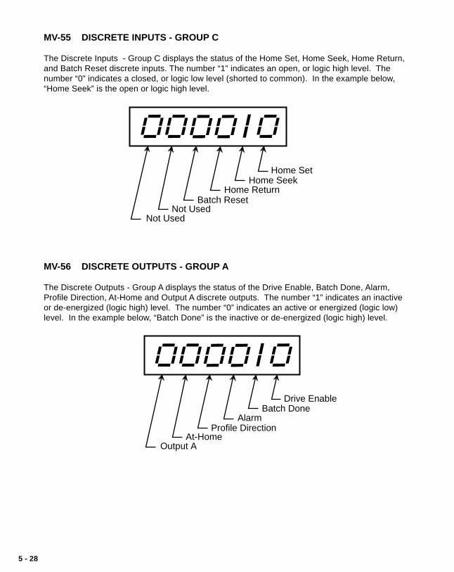
5 - 28
MV-55 DISCRETE INPUTS - GROUP C
The Discrete Inputs - Group C displays the status of the Home Set, Home Seek, Home Return,and Batch Reset discrete inputs. The number “1” indicates an open, or logic high level. Thenumber “0” indicates a closed, or logic low level (shorted to common). In the example below,“Home Seek” is the open or logic high level.
Home SetHome Seek
Home ReturnBatch Reset
Not UsedNot Used
MV-56 DISCRETE OUTPUTS - GROUP A
The Discrete Outputs - Group A displays the status of the Drive Enable, Batch Done, Alarm,Profile Direction, At-Home and Output A discrete outputs. The number “1” indicates an inactiveor de-energized (logic high) level. The number “0” indicates an active or energized (logic low)level. In the example below, “Batch Done” is the inactive or de-energized (logic high) level.
Drive Enable
Batch Done Alarm
Profile Direction At-Home
Output A

5 - 29
MV-57 DISCRETE OUTPUTS - GROUP B
The Discrete Outputs - Group B displays the status of the Output B discrete outputs. Thenumber “1” indicates an inactive or de-energized (logic high) level. The number “0” indicates anactive or energized (logic low) level. In the example below, “Output B” is the inactive or de-energized (logic high) level.
Output BNot Used
Not UsedNot Used
Not UsedNot Used
MV-58 INVALID PROFILE
If a profile entry has been rejected, the Invalid Profile parameter will display the reason that itwas rejected. The M-Traverse will not allow your system to enter "Run" if there is an invalidprofile. The digit that displays a number “1” is the error. In the example below, “The processlength is zero or negative” is the error.
Lead Size or Follower Size > 14,400,000
Process length is either zero or negativeNot Used
Not UsedNot Used
Not Used

5 - 30
MV-59 LINE NOTCH COUNTER
The Line Notch Counter parameter checks the integrity of the AC line. Notches on the line arecaused by inductive loads (e.g., motors, contactors) which cause the counter to increment if theAC line is too low (soft). The Line Notch Counter displays the number of line notches that haveoccurred on the AC line.
CP-60 ACCEL/DECEL
Accel/Decel (CP-60) is the number of seconds in which you want your system to accelerate fromzero RPMs to the Jog Setpoint speed.
NOTE: CP-60 can not be changed during “Run”.
CP-61 JOG SETPOINT
Jog Setpoint (CP-61) is the RPM at which you want your system to operate when it is in Jog.When you activate Jog, the RPMs increase at the acceleration rate that you specified in Accel/Decel (CP-60) until the Jog Setpoint (CP-61) is achieved. Jog can only be entered from F-Stopand when Jog is terminated, the Follower mechanism returns to F-Stop. Jog is used when youneed brief bursts of speed to align the Follower mechanism. The Jog Setpoint (CP-61) is alsoused in the Home Seek and Home Return modes.
CP-62 DIRECT ANALOG COMMAND
The Direct Analog Command (CP-62) parameter uses the full 12 bit resolution of the analogSpeed Command Output.
A value of 4095 is a 100% forward output command.A value of 2048 is a 50% forward output command.0 is a zero output command.
A negative value indicates a reverse output command (e.g., - 4095 is a 100% reversecommand).
CP-65 GAIN
With Integral (CP-66) set to “0” , increase the Gain (CP-65) parameter value until the systembecomes unstable, then decrease it slightly until the system stabilizes. Larger values willincrease Gain. To verify the stability of the speed changes, you can access Tach through eitherthe Tach key or the Tach (MV-40) parameter.
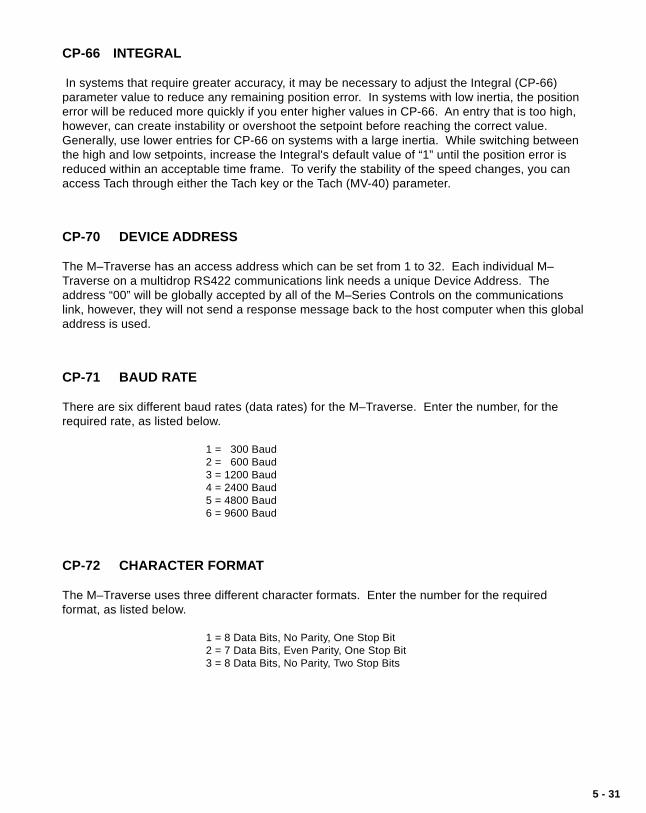
5 - 31
CP-66 INTEGRAL
In systems that require greater accuracy, it may be necessary to adjust the Integral (CP-66)parameter value to reduce any remaining position error. In systems with low inertia, the positionerror will be reduced more quickly if you enter higher values in CP-66. An entry that is too high,however, can create instability or overshoot the setpoint before reaching the correct value.Generally, use lower entries for CP-66 on systems with a large inertia. While switching betweenthe high and low setpoints, increase the Integral's default value of “1” until the position error isreduced within an acceptable time frame. To verify the stability of the speed changes, you canaccess Tach through either the Tach key or the Tach (MV-40) parameter.
CP-70 DEVICE ADDRESS
The M–Traverse has an access address which can be set from 1 to 32. Each individual M–Traverse on a multidrop RS422 communications link needs a unique Device Address. Theaddress “00” will be globally accepted by all of the M–Series Controls on the communicationslink, however, they will not send a response message back to the host computer when this globaladdress is used.
CP-71 BAUD RATE
There are six different baud rates (data rates) for the M–Traverse. Enter the number, for therequired rate, as listed below.
1 = 300 Baud2 = 600 Baud3 = 1200 Baud4 = 2400 Baud5 = 4800 Baud6 = 9600 Baud
CP-72 CHARACTER FORMAT
The M–Traverse uses three different character formats. Enter the number for the requiredformat, as listed below.
1 = 8 Data Bits, No Parity, One Stop Bit2 = 7 Data Bits, Even Parity, One Stop Bit3 = 8 Data Bits, No Parity, Two Stop Bits

5 - 32
CP-73 CONTROL MASK
The Serial Communications can control some of the discrete input functions. Enter the numberfor the required functions, as listed below.
0 = F–Stop only1 = F–Stop, Run, Home Return, Home Seek, Home Set2 = F–Stop, Batch Reset, Setpoint Select 1-43 = All of the Above
MV-74 COMMUNICATIONS ERROR
Serial Communications Error identifies errors in the last transmitted message that was sent tothe M–Traverse by the host computer. The digit that displays a number “1” indicates the error.In the example below, “Invalid Parameter Code” is the error.
Transmit Error (parity, framing, overrun, no ETX, no STX) Parameter Error (invalid parameter code or message type)
Data Error (invalid data)Min-Max Error (out of range)
Control Mask Error or Lockout during Run StateNot Used
CP-79 KEYPAD LOCKOUT MASK
Keypad Lockout Mask is active when the Keypad Lockout input (J4, pins 10,11) is closed. Thevalue that you enter in CP-79 determines which CPs are locked out and inaccessible to theoperator. Enter the number for the required format, as listed below.
1 = All CPs are locked out (Global lockout).2 = All CPs except 01-08 (Setpoints and Traverse Lengths) are locked out.
MV-80 LEAD JOB SIZE
The Lead Job Size displays the total Lead encoder lines that are registered for the most recentjob cycle.

5 - 33
MV-81 FOLLOWER JOB SIZE
The Follower Job Size displays the total Follower encoder lines registered for the forwarddirection of the profile.
MV-84 FOLLOWER PROFILE LENGTH
The Follower Profile Length displays the calculated number of forward encoder lines for theprofile.
MV-86 PROCESS RATIO
The M-Traverse calculates and displays the commanded ratio of the Follower Frequency to theLead Frequency. The commanded ratio is used during the constant pitch plateau segment of theprofile.
MV-87 PROFILE RATIO
The M-Traverse displays the current commanded Follower to Lead ratio for the immediateoperation during the in-line profile execution. MV-87 and MV-86 will be the same value duringthe constant pitch plateau segment of the profile.
MV-89 BATCH COUNT
The M-Traverse calculates and displays the number of completed batch counts (profilecompletion).

5 - 34
CP-90 OUTPUT A SEGMENT
Use the Output A Segment (CP-90) parameter to determine what segment of the Follower profilewill activate Output A.
Enter “1” in CP-90 to activate Output A during the constant pitch plateausegment of the Follower profile.Enter “2” in CP-90 to activate Output A during the constant pitch plateau andAccel/Decel segments of the Follower profile.Enter “3” in CP-90 to activate Output A during the dwell segment of theFollower profile.
The diagram below illustrates the segments of the Follower profile :
ConstantPitch
Plateau
Follower Profile
Acc
el/D
ecel
Accel/D
ecel Dwell
1
2
3
CP-91 OUTPUT A DIRECTION
Use the Output A Direction (CP-91) parameter to specify the direction in which Output A willoperate.
Enter “1” in CP-91 to activate Output A during the forward direction.Enter “2” in CP-91 to activate Output A during the reverse direction.Enter “3” in CP-91 to activate Output A during the forward and reversedirections.
CP-92 OUTPUT A POLARITY
Use the Output A Polarity (CP-92) parameter to specify the voltage polarity at which Output A willoperate.
Enter “0” in CP-92 to activate Output A as Active Low Voltage Level.Enter “1” in CP-92 to activate Output A as Active High Voltage Level.

5 - 35
CP-93 OUTPUT B SEGMENT
Use the Output B Segment (CP-93) parameter to determine what segment of the Follower profilewill activate Output B.
Enter “1” in CP-93 to activate Output B during the constant plateau segment ofthe Follower profile.Enter “2” in CP-93 to activate Output B during the constant plateau and Accel/Decel segments of the Follower profile.Enter “3” in CP-93 to activate Output B during the dwell segment of theFollower profile.
The diagram below illustrates the segments of the Follower profile:
ConstantPitch
Plateau
Follower Profile
Acc
el/D
ecel
Accel/D
ecel Dwell
1
2
3
CP-94 OUTPUT B DIRECTION
Use the Output B Direction (CP-94) parameter to specify the direction in which Output B willoperate.
Enter “1” in CP-94 to activate Output B during the forward direction.Enter “2” in CP-94 to activate Output B during the reverse direction.Enter “3” in CP-94 to activate Output B during the forward and reversedirections.
CP-95 OUTPUT B POLARITY
Use the Output B Polarity (CP-95) parameter to specify the voltage polarity at which Output Bwill operate.
Enter “0” in CP-95 to activate Output B as Active Low Voltage Level.Enter “1” in CP-95 to activate Output B as Active High Voltage Level.
MV-99 SOFTWARE CODE REVISION
MV-99 displays the code revision number of the M–Traverse's software (EPROM).
MV-00 SOFTWARE PART NUMBER
MV-00 displays the last four digits of the eight digit part number for the M–Traverse's software(EPROM). The first four digits are assumed to be “1000”.

5 - 36
APPENDIX D: CONTROL PARAMETERREFERENCE
USER
CODE DESCRIPTION MIN MAX DEFAULT RECORD UNITS
CP-01 Setpoint 1 000.000 999999 0.000 E.U.
CP-02 Traverse Length 1 000.000 999999 0.000 E.U.
CP-03 Setpoint 2 000.000 999999 0.000 E.U.
CP-04 Traverse Length 2 000.000 999999 0.000 E.U.
CP-05 Setpoint 3 000.000 999999 0.000 E.U.
CP-06 Traverse Length 3 000.000 999999 0.000 E.U.
CP-07 Setpoint 4 000.000 999999 0.000 E.U.
CP-08 Traverse Length 4 000.000 999999 0.000 E.U.
CP-09 Accel/Decel Length 0 65535 0 Lead Lines
CP-10 Dwell 0 65535 0 Lead Lines
CP-14 Control Mode 1 3 1 Coded
CP-15 Engineering Units 000.000 999999 0.000 E.U.
CP-16 Lead PPR Reel 0 999999 1000 Lead Lines
CP-17 Foll Lines per EU. 0 999999 1000 Lines/EU
CP-18 PPR-Follower 60 6000 60 PPR
CP-19 Max RPM - Follower 100 30000 2000 RPM
CP-23 High Speed Alarm 0 30000 2000 RPM
CP-24 Edge/Ctr Based Profile 1 2 1 Coded
CP-25 Change Activation 1 3 1 Coded
CP-26 Batch Format 1 2 1 Coded
CP-27 Batch Limit 0 9999 0 Counts
CP-28 Batch Preact Distance 000.000 999999 999999 E.U.
CP-29 Unipolar/Bipolar 1 2 2 Coded
CP-30 At-Home Band 1 60000 4 Foll Lines
CP-31 Home Offset -99999 999999 0 E.U.
CP-32 Resume Enable 1 3 1 Coded
CP-35 Home Sync Polarity 1 2 1 Coded
CP-36 Fwd/Rev Limit Polarity 1 2 2 Coded
CP-37 Forward Limit Format 1 2 1 Coded
CP-60 Accel/Decel 0.1 600.0 5.0 Seconds
(continued)

5 - 37
APPENDIX D: CONTINUED
USER
CODE DESCRIPTION MIN MAX DEFAULT RECORD UNITS
CP-61 Jog Setpoint 0 30000 50 RPM
CP-62 Direct Analog Command -4095 4095 0 DAC Bits
CP-65 Gain 0 30000 3000 N/A
CP-66 Integral 0 30000 1 N/A
CP-70 Device Address 1 32 1 N/A
CP-71 Baud Rate 1 6 6 Coded
CP-72 Character Format 1 3 2 Coded
CP-73 Control Mask 0 3 0 Coded
CP-79 Keypad Lockout Mask 1 2 1 Coded
CP-90 Output A Segment 1 3 1 Coded
CP-91 Output A Direction 1 3 1 Coded
CP-92 Output A Polarity 0 1 0 Coded
CP-93 Output B Segment 1 3 1 Coded
CP-94 Output B Direction 1 3 1 Coded
CP-95 Output B Polarity 0 1 0 Coded
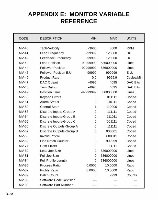
5 - 38
APPENDIX E: MONITOR VARIABLEREFERENCE
CODE DESCRIPTION MIN MAX UNITS
MV-40 Tach-Velocity -3600 3600 RPM
MV-41 Lead Frequency -99999 120000 Hz
MV-42 Feedback Frequency -99999 120000 Hz
MV-43 Lead Position -99999999 536000000 Lines
MV-44 Follower Position -99999999 536000000 Lines
MV-45 Follower Position E.U. -99999 999999 E.U.
MV-46 Product Rate 0.0 9999.9 Cycles/Min
MV-47 DAC Output -4095 4095 DAC Bits
MV-48 Trim Output -4095 4095 DAC Bits
MV-49 Position Error -99999999 536000000 Lines
MV-50 Keypad Errors 0 011111 Coded
MV-51 Alarm Status 0 010111 Coded
MV-52 Control State 1 110000 Coded
MV-53 Discrete Inputs-Group A 0 111111 Coded
MV-54 Discrete Inputs-Group B 0 111011 Coded
MV-55 Discrete Inputs-Group C 0 001111 Coded
MV-56 Discrete Outputs-Group A 0 111111 Coded
MV-57 Discrete Outputs-Group B 0 000001 Coded
MV-58 Invalid Profile 0 000011 Coded
MV-59 Line Notch Counter 0 999999 Coded
MV-74 Com Errors 0 11111 Coded
MV-80 Lead Job Size 0 536000000 Lines
MV-81 Foll Job Size 0 536000000 Lines
MV-84 Foll Profile Length 0 536000000 Lines
MV-86 Process Ratio 0.0000 10.0000 Ratio
MV-87 Profile Ratio 0.0000 10.0000 Ratio
MV-89 Batch Count 0 9999 Counts
MV-99 Software Code Revision — — —
MV-00 Software Part Number — — —

5 - 39
APPENDIX F: FAX COVER SHEET
Date: ______________________
Atten: Contrex Technical Support
From:Name ____________________________________ Ext______________
Company _________________Telephone #__________________Fax # _________________
We have ______ M-Traverses that are used for: ________________________________
_______________________________________________________________________
_______________________________________________________________________
Serial Communication Hookup: _____Yes _____No
Brief Description of the Problem: ___________________________________________
______________________________________________________________________
______________________________________________________________________
______________________________________________________________________
______________________________________________________________________
______________________________________________________________________
______________________________________________________________________
Contrex Fax # = (763) 424-8734
We are transmitting _____ pages, including:• a copy of this Cover Sheet,
• a copy of Appendix D with the User Record completed,
• a sketch of the system that the M-Traverse is integrated with.

5 - 40
APPENDIX G: WIRING DIAGRAMEXAMPLES
WARNING
This diagram is for conceptual purposes only!Use safety equipment.
Make wiring connections carefully.Incorrect use of equipment or connections
can cause injury or death.
1
2
3
4
5
6
7
8
9
10
11
12
13
14
15
16
17
18
19
20
+ VDC
SIGNAL
ISO COMMON
J1
1
2
3
4
5
6
7
8
9
10
11
12
13
14
15
16
17
18
J4
ISOLATED OUTPUTTO DRIVE RUN
F-STOP
JOG
VOLTAGE REFERENCE
SPEED COMMAND OUT
ISOLATED COMMON
SHIELD
M-Traverse
RUN
F-STOP
JOG
Figure G-1 M–Traverse Wiring Connections without Relays

5 - 41
WARNING
This diagram is for conceptual purposes only!Use safety equipment.
Make wiring connections carefully.Incorrect use of equipment or connections
can cause injury or death.
Figure G-2 Relay Run/Stop Wiring Connections
1
2
3
4
5
6
7
8
9
10
11
12
13
14
15
16
17
18
19
20
+ VDC
SIGNAL
ISO COMMON
J1
1
2
3
4
5
6
7
8
9
10
11
12
13
14
15
16
17
18
J4
ISOLATED OUTPUTTO DRIVE
RUN
F-STOP
JOG
K-J
\K-R
K-J
K-FS
K-J
Start
K-RK-R
NeutralLine
F-Stop
K-FS
K-J
Run
Jog
K-R
K-J
K-FS
VOLTAGE REFERENCE
SPEED COMMAND OUT
ISOLATED COMMON
SHIELD
M-Traverse
\
RUN
F-STOP
JOG

5 - 42
WARNING
This diagram is for conceptual purposes only!Use safety equipment.
Make wiring connections carefully.Incorrect use of equipment or connections
can cause injury or death.
Figure G-3 Run/Stop for Regen with Armature Contactor
1
2
3
4
5
6
7
8
9
10
11
12
13
14
15
16
17
18
19
20
J1
1
2
3
4
5
6
7
8
9
10
11
12
13
14
15
16
17
18
J4
RUN
F-STOP
JOG
+ —
12 VoltPowerSupply
LineK-R
M1
ArmatureContactor
K-R
V+
SPD
RegenDrive
K-RRun
VREFVOLTAGE REFERENCE
SPEED COMMAND OUT
ISOLATED COMMON
SHIELD
EXT. SUPPLY
DRIVE ENABLE
M-Traverse
Neutral
RUN
F-STOP
JOG

5 - 43
WARNING
This diagram is for conceptual purposes only!Use safety equipment.
Make wiring connections carefully.Incorrect use of equipment or connections
can cause injury or death.
Figure G-4 Run/Stop for Non-Regen with Armature Contactor
1
2
3
4
5
6
7
8
9
10
11
12
13
14
15
16
17
18
19
20
+ VDC
SIGNAL
ISO COMMON
J1
1
2
3
4
5
6
7
8
9
10
11
12
13
14
15
16
17
18
J4
ISOLATED OUTPUTTO DRIVE M1-AUX 1
VOLTAGE REFERENCE
SPEED COMMAND OUT
ISOLATED COMMON
SHIELD
F-Stop Start
M1-AUX1ArmatureContactor
M1
NeutralLine
M-Traverse
RUN
F-STOP
JOG
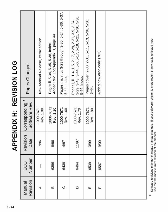
5 - 44
AP
PE
ND
IX H
: R
EV
ISIO
N L
OG
Man
ual
Rev
isio
nE
CO
Num
ber
Rev
isio
nD
ate
Cor
resp
ondi
ng *
Sof
twar
e R
ev.
Pag
es C
hang
ed
A—
7/96
1000
-767
1R
ev. 1
.00
New
Man
ual R
elea
se, x
erox
edi
tion
* S
oftw
are
revi
sion
s m
ay n
ot m
anda
te m
anua
l cha
nges
. If
your
sof
twar
e re
visi
on is
mor
e re
cent
than
wha
t is
refle
cted
her
e,
use
the
the
mos
t cur
rent
rev
isio
n of
the
man
ual.
B63
969/
9610
00-7
671
Rev
. 1.2
0P
ages
ii, 5
-34,
5-3
5, 5
-38,
Inde
x.
Add
ed R
ev. L
og/A
ppen
dix
H, p
age
44
C64
394/
9710
00-7
671
Rev
. 1.6
0P
ages
i, ii
, v, v
i, 3-
28 th
roug
h 3-
80, 5
-24,
5-3
6, 5
-37,
5-44
, Ind
ex.
Pag
es i,
iii,
1-4,
1-5
, 2-1
7, 2
-29,
2-3
1, 3
-9, 3
-24,
3-
29, 3
-43,
3-4
4, 5
-6, 5
-17,
5-1
8, 5
-21,
5-3
0, 5
-36,
5-
44, I
ndex
.D
6464
11/9
7
E65
393/
99
1000
-767
1R
ev. 1
.70
1000
-767
1R
ev. 1
.80
Pag
es c
over
, 2-3
0, 2
-31,
5-1
1, 5
-13,
5-3
6, 5
-38,
5-
44.
F65
879/
00A
dded
new
are
a co
de (
763)
.

5 - 45
SERVICE POLICYContrex, Inc., recognizes that with each sale ofits product there are certain productobligations. This document defines the limitsof such obligations and provides guidelines forthe performance of related services.
Applicability This Service Policy shall apply to all productsales of Contrex, Inc. However, it may bemodified by mutual consent. Thus, wheneveran accepted proposal contains wordinginconsistent with this policy, the proposal willprevail with respect to specific sale or series ofsales involved. Applicability of this policy isalso somewhat limited in cases whereproducts are sold to an OEM for resale touser. See paragraph below entitled OEMService.
Service PersonnelContrex, Inc., has a staff whose primaryresponsibility is service - both factory serviceand field (on-site) service. Personnel of thisdepartment are usually available for service ona 24 hour notice. To facilitate quickerhandling of service requests, either written orby phone, such requests should be directed tothe Contrex, Inc., Technical ServicesDepartment.
Service ChargesContrex, Inc., reserves the right to charge forall services performed at the customersrequest with the exception of factory serviceperformed under warranty. All on-site serviceis charged at flat-rate per diem rates plusexpenses. Any Contrex, Inc., productdeveloping defects as defined in the warrantyduring its effective period will be repaired orreplaced without charge, providing it isshipped, prepaid, to Contrex, Inc., 8900Zachary Lane North, Maple Grove, Minnesota55369.
Spare PartsContrex, Inc., will usually have an adequateinventory of spare parts and circuit boards for
all standard products. However, purchasersare encouraged to maintain a nominal supplyof spare parts to insure immediate on-siteaccessibility.
Instruction ManualsInstructions for installation, maintenance andtroubleshooting are included in manuals thatare provided with the equipment. Repairs maybe performed in the field by competentcustomer personnel; but in order to notinvalidate the warranty they must be made instrict accordance with published instructions,and ONLY AFTER obtaining approval of theTechnical Service Department (such repairsare usually limited to the replacement of circuitboards and major subassemblies, not therepair of these items).
OEM ServiceIn many instances Contrex, Inc., products aresold to the original equipment manufactures orintegrators for inclusion in larger systems. Insuch cases the obligations of Contrex, Inc.,extend only to that original purchaser. It is thelatter's responsibility to handle any servicerequired by his customer, the end user. Suchproblems can usually be solved by fieldreplacement of complete units. OEM's areencouraged to buy and maintain a supply of“loaners” for this purpose. Contrex, Inc., willprovide factory overhaul service at nominalcharges to support that OEM. Users ofContrex, Inc., products that were acquired ascomponents of larger systems may buyservice or spare parts directly from Contrex,Inc., at standard prices, but they must appealthrough the OEM for warranty service.
If Contrex, Inc., encounters trouble in the fieldwhich appears to be the result of fault orinadequacy of the system, Contrex, Inc.,reserves the right to recover service chargesfrom the party that authorized the serviceactivity.

5 - 46
WARRANTY
Contrex, Inc., guarantees this device againstdefects in workmanship and materials for aperiod of one (1) year from the date ofpurchase. Any parts or components that failduring the warranty period will be replaced orrepaired without charge. This guarantee isvoid if the device has been damaged byimproper installation or operation, tampering,careless handling or accident.
When a device fails to function in accordancewith standards set forth in the instructionmanual, the purchaser should contact anauthorized representative of Contrex, Inc.,8900 Zachary Lane North, Maple Grove,Minnesota 55369. Whether repairs will takeplace in the field or at the factory will be solelythe prerogative of Contrex, Inc.
If inspection reveals defects that are causedby faulty materials or workmanship, Contrex,Inc., reserves the right to either replace thedevice or rebuild the device using new orrefurbished warranted parts and components.In either instance, the device that is returnedto the purchaser meets full factory standardsfor new device performance. If there is lessthan 90 days remaining on the warranty periodat the time of the repair, the warranty willextend to 90 days after the repair.
Parts and services outside the scope of thiswarranty will be available at Contrex, Inc.,current market price.
Contrex's liability for a device or it's use,whether in warranty or not, shall not in anyinstance exceed the cost of correcting thedefects of the device. Contrex, Inc., assumesno responsibility for damage to property orinjuries to persons from improper use of thisdevice.
No express warranties and no impliedwarranties whether of merchantability orotherwise (except as to title), other than thoseset forth above , which are expressly made inlieu of all other warranties, shall apply to anydevise sold by Contrex, Inc.
Contrex, Inc., reserves the right to change orimprove its devices without imposing anyobligation upon Contrex, Inc., to make changesor improvements in previously manufactureddevices.
This warranty statement is a summary ofContrex, Inc's policy. Further limits of liabilityare contained in the Contrex, Inc's purchaseorder acknowledgments and invoices.

5-47
INDEX
Symbols—/Alt p. 3-3
AAccel/Decel p. 3-30, 5-30, 5-36Accel/Decel Length p. 3-17, 5-16, 5-36Alarm Output p. 2-20, 3-36Alarm Status p. 3-60, 5-26, 5-38Annunciator Test p. 4-6Appendix A p. 5-11Appendix B p. 5-13Appendix C p. 5-14Appendix D p. 5-36, 5-37Appendix E p. 5-38Appendix F p. 5-39Appendix G p. 5-40Appendix H p. 5-44Applications / M-Traverse p. 1-4At-Home Band p. 3-21, 3-23, 3-37, 5-21, 5-36At-Home Output p. 3-37Auxiliary DC Power p. 2-22
BBatch Control Parameters p. 3-34Batch Count p. 3-62, 5-33, 5-38Batch Count Key p. 3-4Batch Count Key, To Use the p. 3-4Batch Done p. 2-20Batch Format p. 3-34, 3-35, 5-20, 5-36Batch Limit p. 3-34, 3-35, 5-21, 5-36Batch PreAct Distance p. 3-34, 3-35, 5-21, 5-36Batch Reset p. 2-14Baud Rate p. 3-64, 5-31, 5-37
CCalibration p. 2-27Calibration - Definition p. 5-3Center Based Profile with Home Offset p. 3-48Change Activation p. 3-23, 5-19, 5-36Character Format p. 3-65, 5-31, 5-37Clear p. 3-3

5-48
Clear/4 Test p. 4-3Closed Loop p. 5-3Code Select Key p. 3-3Communications Error p. 3-65, 5-32, 5-38Communications Software Design p. 3-66Configuration p. 2-3Control Command Send p. 3-71, 5-3Control Command Send - Host Transmission p. 3-71Control Command Send - M–Traverse Response p. 3-73Control Mask p. 3-65, 5-32, 5-37Control Mode p. 3-29, 5-17, 5-36Control Parameter Reference List p. 5-36, 5-37Control Parameters p. 3-7, 3-53, 5-4Control State p. 3-61, 5-26, 5-38CP-01 p. 3-14, 5-14, 5-36CP-02 p. 3-15, 5-14, 5-36CP-03 p. 3-14, 5-14, 5-36CP-04 p. 3-15, 5-15, 5-36CP-05 p. 3-14, 5-15, 5-36CP-06 p. 3-15, 5-15, 5-36CP-07 p. 3-14, 5-15, 5-36CP-08 p. 3-15, 5-16, 5-36CP-09 p. 3-17, 5-16, 5-36CP-10 p. 3-18, 5-16, 5-36CP-14 p. 3-29, 5-17, 5-36CP-15 p. 3-12, 5-17, 5-36CP-16 p. 3-12, 5-17, 5-36CP-17 p. 3-12, 5-18, 5-36CP-18 p. 3-12, 5-18, 5-36CP-19 p. 3-12, 5-18, 5-36CP-23 p. 3-36, 5-18, 5-36CP-24 p. 3-23, 5-19, 5-36CP-25 p. 3-23, 5-19, 5-36CP-26 p. 3-35, 5-20, 5-36CP-27 p. 3-35, 5-21CP-28 p. 3-35, 5-21, 5-36CP-29 p. 2-30, 5-21, 5-36CP-30 p. 3-23, 3-37, 5-21, 5-36CP-31 p. 3-23, 5-22, 5-36CP-32 p. 3-26, 5-23, 5-36CP-35 p. 5-23, 5-36CP-36 p. 5-23, 5-36CP-37 p. 5-24, 5-36CP-60 p. 3-30, 5-30, 5-36CP-61 p. 3-30, 5-30, 5-37
5-49
CP-62 p. 3-29, 5-30, 5-37CP-65 p. 3-33, 5-30, 5-37CP-66 p. 3-33, 5-31, 5-37CP-70 p. 3-64, 5-31, 5-37CP-71 p. 3-64, 5-31, 5-37CP-72 p. 3-65, 5-31, 5-37CP-73 p. 3-65, 5-32, 5-37CP-79 p. 3-7, 5-32, 5-37CP-90 p. 3-39, 5-34, 5-37CP-91 p. 3-39, 5-34, 5-37CP-92 p. 3-39, 5-34, 5-37CP-93 p. 3-41, 5-35, 5-37CP-94 p. 3-41, 5-35, 5-37CP-95 p. 3-41, 5-35, 5-37CPU Watchdog Failure p. 4-12
DDAC Output p. 3-56, 5-25, 5-38Data Inquiry p. 3-75, 5-4Data Inquiry - Host Transmission p. 3-75Data Inquiry - M–Traverse Response p. 3-77Dedicated Keys p. 5-4Device Address p. 3-64, 5-31, 5-37Diagnostic Testing p. 4-3Diagnostics p. 2-7, 4-3Diagnostics - Automatic Test Routines p. 4-11Digital Motor Controller p. 5-4Direct Analog Command p. 3-29, 5-30, 5-37Direct Mode p. 3-29, 3-51, 5-4Discrete Inputs p. 5-5Discrete Inputs - Group A p. 3-54, 5-27, 5-38Discrete Inputs - Group B p. 3-55, 5-27, 5-38Discrete Inputs - Group C p. 3-55, 5-28, 5-38Discrete LED Display p. 3-4Discrete Outputs - Group A p. 3-56, 5-28, 5-38Discrete Outputs - Group B p. 3-57, 5-29, 5-38Display Test p. 4-5Drive Enable p. 2-19Dwell p. 3-18, 5-16, 5-36
EEdge Based Profile with Home Offset p. 3-47Edge Based Profile with No Home Offset p. 3-46Edge Based Profile with Reverse Rebound p. 3-49Edge/Center Based p. 3-23

5-50
Edge/Center Based Profile p. 3-19, 5-19, 5-36Encoder Polarity Check p. 2-29Engineering Units p. 3-10, 3-12, 5-5, 5-17, 5-36EPROM Chip p. 5-5EPROM Chip Replacement p. 4-19EPROM Test p. 4-5
FF–Stop p. 2-16, 5-5Fax Cover Sheet p. 5-39Feedback Frequency p. 2-11, 3-54, 5-24, 5-38Follower Job Size p. 3-62, 5-33, 5-38Follower Lines per Engineering Units p. 3-10, 3-12, 5-18, 5-36Follower Mode p. 3-8, 3-44, 5-5Follower Mode / Lay Adjusted Application p. 1-5Follower Mode, Standard Application p. 1-4Follower Position p. 3-59, 5-24, 5-38Follower Position - E.U. p. 3-59, 5-24, 5-38Follower Profile Length p. 3-62, 5-33, 5-38Follower Profile Parameters p. 3-17Follower Scaling Parameters p. 3-10Formulas p. 5-13Forward Limit p. 2-17Forward Limit Format p. 5-24, 5-36Forward/Reverse Limit Polarity p. 3-27, 5-23, 5-36Frequency Input p. 2-3
GGain p. 3-33, 5-30, 5-37Glossary p. 5-3
HHardwired p. 5-6High Speed Alarm p. 3-36, 5-18, 5-36Home Offset p. 3-21, 3-23, 5-22, 5-36Home Return p. 2-14, 3-50Home Seek p. 2-13, 3-45Home Set p. 2-13, 3-45Home Sync p. 2-11Home Sync Polarity p. 3-27, 5-23, 5-36How to Replace the EPROM Chip p. 4-19
IInput Monitoring p. 3-54, 5-6Input Power p. 2-10
5-51
Input Test p. 4-8Inputs p. 5-6Integral p. 3-33, 5-31, 5-37Introducing the M—Traverse p. 1-3Invalid Profile p. 3-61, 5-29, 5-38Isolator Voltage jumper p. 2-3
JJ1 pin 13 p. 2-19J1 pin 14 p. 2-20J1 pin 15 p. 2-20J1 pin 16 p. 2-20J1 pin 17 p. 2-21J1 pin 18 p. 2-21J1 pin 19 p. 2-21J1 pins 8, 9,10,11 p. 2-19J2 pins 1, 2, 3 p. 2-10J3 pins 1,2 p. 2-22J3 pins 13,14 p. 2-12J3 pins 14,15 p. 2-12J3 pins 14,16 p. 2-13J3 pins 3,4,5,6 p. 2-10J3 pins 6,11,12 p. 2-11J3 pins 6,7,8,9 p. 2-11J4 pins 10,11 p. 2-16J4 pins 1,2 p. 2-13J4 pins 12,13 p. 2-17J4 pins 13,14 p. 2-17J4 pins 15,16 p. 2-18J4 pins 16, 17 p. 2-18J4 pins 3,4 p. 2-14J4 pins 4,5 p. 2-14J4 pins 6,7 p. 2-15J4 pins 7,8 p. 2-15J4 pins 9,10 p. 2-16Jog p. 2-18, 3-30, 3-52Jog Forward/Reverse p. 2-18Jog Setpoint p. 3-30, 5-30, 5-37
KKeypad, Basic Entry p. 3-4Keypad Error p. 3-60, 5-25, 5-38Keypad Lockout p. 2-16Keypad Lockout Mask p. 5-32, 5-37Keypad Operation p. 3-3

5-52
Keypad Test p. 4-7Keys, Numeric p. 3-3, 5-7
LLay Adjusted / Follower Mode p. 1-5Lead Frequency p. 2-10, 3-54, 5-24, 5-38Lead Job Size p. 3-62, 5-32, 5-38Lead Position p. 3-58, 5-24, 5-38Lead PPR Reel p. 3-10, 3-12, 5-17, 5-36LED Display p. 5-7Level Wind p. 1-4Line Notch Counter p. 3-62, 5-30, 5-38Lower LED Display p. 3-4
MM–Traverse Applications p. 1-4M–Traverse Calibration p. 2-30M–Traverse Operation p. 3-43Maximum RPM Follower p. 3-11, 5-18, 5-36Mode of Operation p. 5-7Monitor Variables p. 3-7, 3-53, 5-7Motor Does Not Run p. 4-13Motor Does Not Stop p. 4-13Motor Drive Set Up p. 2-29Motor Runs at Wrong Speed p. 4-13Motor Runs Unstable p. 4-13Mounting p. 2-7MV-00 p. 5-35, 5-38MV-40 p. 3-58, 5-24, 5-38MV-41 p. 3-54, 5-24, 5-38MV-42 p. 3-54, 5-24, 5-38MV-43 p. 3-58, 5-24, 5-38MV-44 p. 3-59, 5-24, 5-38MV-45 p. 3-59, 5-24, 5-38MV-46 p. 3-59, 5-25, 5-38MV-47 p. 3-56, 5-25, 5-38MV-48 p. 3-56, 5-25, 5-38MV-49 p. 3-59, 5-25, 5-38MV-50 p. 3-60, 5-25, 5-38MV-51 p. 3-60, 5-26, 5-38MV-52 p. 3-61, 5-26, 5-38MV-53 p. 3-54, 5-27, 5-38MV-54 p. 3-55, 5-27, 5-38MV-55 p. 3-55, 5-28, 5-38MV-56 p. 3-56, 5-28, 5-38

5-53
MV-57 p. 3-57, 5-29, 5-38MV-58 p. 3-61, 5-29, 5-38MV-59 p. 3-62, 5-30, 5-38MV-74 p. 3-65, 5-32, 5-38MV-80 p. 3-62, 5-32, 5-38MV-81 p. 3-62, 5-33, 5-38MV-84 p. 3-62, 5-33, 5-38MV-86 p. 3-62, 5-33, 5-38MV-87 p. 3-62, 5-33, 5-38MV-89 p. 3-62, 5-33, 5-38MV-99 p. 5-35, 5-38
NNumeric Keys. See Keys, Numeric
OOpen Loop p. 5-8Operating State p. 5-8Other Follower Parameters p. 3-19Output A p. 2-21Output A Direction p. 3-38, 3-39, 5-34, 5-37Output A Polarity p. 3-38, 3-39, 5-34, 5-37Output A Segment p. 3-38, 3-39, 5-34, 5-37Output B p. 2-21, 3-40Output B Direction p. 3-40, 3-41, 5-35, 5-37Output B Polarity p. 3-40, 3-41, 5-35, 5-37Output B Segment p. 3-40, 3-41, 5-35, 5-37Output Control p. 3-34Output Monitoring p. 3-56, 5-8Output Test p. 4-9Outputs p. 2-19, 5-8
PParameter Code p. 5-8Parameter Code, To Enter a p. 3-4Parameter Send p. 3-67, 5-8Parameter Send - Host Transmission p. 3-67Parameter Send - M–Traverse Response p. 3-69Parameter Summary Reference List p. 5-14Parameter Value p. 5-8Parameter Value, To Enter a p. 3-4Parameters p. 5-8Performance Monitoring p. 3-58, 5-9Polarity Check, Encoder p. 2-29Position Error p. 3-59, 5-25, 5-38

5-54
Power Failure p. 4-12Power Voltage switch p. 2-3PPR Follower p. 2-30, 3-11, 3-12, 5-18, 5-36Preset Parameters p. 3-13Process Ratio p. 3-62, 5-33, 5-38Product Rate p. 3-59, 5-25, 5-38Profile Direction p. 2-20Profile Ratio p. 3-62, 5-33, 5-38PROM Test p. 4-11
QQuadrature Position p. 2-3
RRAM Test p. 4-4, 4-11Relay Run/Stop Wiring Connections p. 5-41Resume Enable p. 3-24, 3-26, 5-23, 5-36Reverse Limit p. 2-17Revision Log p. 5-44Ring Kits p. 5-9RPM Feedback p. 5-9RPM Lead p. 5-9Run p. 2-15, 5-9Run/Stop for Non-Regen with Armature Contactor p. 5-43Run/Stop for Regen with Armature Contactor p. 5-42
SScaling p. 5-9Serial Communications p. 3-63, 5-9Serial Input Test p. 4-10Service Policy p. 5-45Setpoint p. 3-3Setpoint 1 p. 3-14, 5-14, 5-36Setpoint 2 p. 3-14, 5-14, 5-36Setpoint 3 p. 3-14, 5-15, 5-36Setpoint 4 p. 3-14, 5-15, 5-36Setpoint Key. See Keys, SetpointSetpoint Key, To Use the p. 3-4Setpoint Select A p. 2-12Setpoint Select B p. 2-12Setpoints p. 3-13Software Code Revision p. 5-35, 5-38Software Part Number p. 5-35, 5-38
5-55
Standard Application / Follower mode p. 1-4Status Key p. 3-4Status Key, To Use the p. 3-4Status Monitoring p. 3-60, 5-10Support - Technical. See Technical Support
TTach p. 3-58, 5-24Tach Key p. 3-3Tach Key, To Use the p. 3-4Tach-Velocity p. 5-38Technical Support p. ii, 4-3, 4-13Test the Micro Controller p. 4-4Test Programmable Read Only Memory p. 4-5Test Random Access Memory p. 4-4Test the Discrete Inputs p. 4-8Test the Discrete LED Indicator Display p. 4-6Test the Discrete Outputs p. 4-9Test the Keypad p. 4-7Test the Serial Input p. 4-10Test the Speed Command Out p. 4-9Test Upper and Lower LED Display Panel Segments p. 4-5Traverse Length p. 3-14Traverse Length 1 p. 3-15, 5-14, 5-36Traverse Length 2 p. 3-15, 5-15, 5-36Traverse Length 3 p. 3-15, 5-15, 5-36Traverse Length 4 p. 3-15, 5-16, 5-36Trim Output p. 3-56, 5-25, 5-38Troubleshooting p. 4-13Tuning p. 3-32, 5-9
UUnipolar/Bipolar p. 5-21, 5-36Upper LED Display p. 3-4Using Serial Communications p. 3-64
WWait p. 2-15Warranty p. 5-46Watchdog Failure p. 4-12Web Scanning p. 1-5Wiring - Examples p. 5-40Wiring Connections without Relays p. 5-40


![[0122 구경원]게임에서의 충돌처리](https://img.pdfslide.net/doc/110x75/559e18dc1a28ab3e798b4850/0122-.jpg)