Embed Size (px)
Citation preview

MTS 5200
ENGINE ANALYZER
Operator’s Manual

Vetronix Corporation
Copyright ©2006
Manual P/N 08002903 Version B
Ver. 1.1
The trademarks, logos, and service marks (“Marks”) displayed in this document are the property of Vetronix or other third parties. Users are not permitted to use these Marks without the prior written consent of Vetronix or such third party which may own the Mark. “Vetronix” is a registered trademark of Vetronix Corporation.
Mastertech® is a registered trademark of Vetronix Corp.
Printed in USA 3/06
Vetronix Corporation Proprietary Statement
This entire document and all information contained herein are proprietary, confidential, and exclusive trade secret property of Vetronix Corporation and shall not be reproduced, duplicated, or copied in whole or in part, or made available to any other person, firm, or corporation without the prior written permission of Vetronix Corporation.

SOME THINGS YOU SHOULD KNOW
DISCLAIMER
The MTS 5200 tester is designed for use by trained service personnel only. The tester has been developed for the sole purpose of diagnosing and repairing automotive electronic systems. Every attempt has been made to provide complete and accurate technical information based on factory service information available at the time of publication. However, the right is reserved to make changes at any time without notice.
FCC COMPLIANCE
This equipment has been tested and found to comply with the limits for a Class A digital device, pursuant to Part 15 of the FCC Rules. These limits are designed to provide reasonable protection against harmful interference when the equipment is operated in a commercial environment. This equipment generates, uses, and can radiate radio frequency energy and, if not installed and used in accordance with the instruction manual, may cause harmful interference to radio communications. Operation of this equipment in a residential area is likely to cause harmful interference in which case the user will be required to correct the interference at his own expense.
WARNING! When performing any checks with the engine running in an enclosed space such as a garage, be sure there is proper ventilation. Never inhale exhaust gases; they contain carbon monoxide, a colorless, odorless, extremely dangerous gas which can cause unconsciousness or death.
CAUTION
CAUTION!Always set the parking brake securely and block the drive wheels before performing any checks or repairs on the vehicle.

Table of Contents
1. INTRODUCTION TO THE MTS 5200 ...................................................................... 1
INTRODUCTION ................................................................................................................ 1
ABOUT THE OPERATOR’S MANUAL ....................................................................... 1
SAFETY GUIDELINES ..................................................................................................... 2
MTS 5200 FEATURES ....................................................................................................... 3General Functions ............................................................................................................ 3Ignition Scope Connections .............................................................................................. 6Keypad Operation Functions ........................................................................................... 7Communication Connections ........................................................................................... 7Standard Leads ................................................................................................................. 8Optional Leads ............................................................................................................... 10Touch Screen Operation ................................................................................................. 11
GENERAL INFORMATION .......................................................................................... 12Connecting the Battery ................................................................................................... 12Powering the Tester ........................................................................................................ 13Selecting a Language ..................................................................................................... 14Entering the Test Vehicle ................................................................................................ 14Freeze .............................................................................................................................. 19Powering Down the Tester ............................................................................................. 21
2. USING THE 4-CHANNEL OSCILLOSCOPE ................................................... 22
INTRODUCTION .............................................................................................................. 22
CONNECTING LEADS ................................................................................................... 23
PATTERN DISPLAY ....................................................................................................... 24Manual Setup .................................................................................................................. 24Component Selection ...................................................................................................... 24Signal Finder .................................................................................................................. 27Default Setup .................................................................................................................. 27
CHANNEL CONTROLS ................................................................................................. 27Volts/Division .................................................................................................................. 28Offset ............................................................................................................................... 28AC/DC Coupling ............................................................................................................. 29Time/Division .................................................................................................................. 31
TRIGGER SETUP .............................................................................................................. 32Trigger Source ................................................................................................................ 32Trigger Type .................................................................................................................... 33Trigger Level ................................................................................................................... 34Trigger Position .............................................................................................................. 35Trigger Edge ................................................................................................................... 35
GLITCH CAPTURE .......................................................................................................... 36
FREEZE ............................................................................................................................... 36
SNAPSHOT ......................................................................................................................... 36
CURSORS ........................................................................................................................... 37Cursor Controls .............................................................................................................. 38
MTS 5200 Engine Analyzer i

Cursor Movement ........................................................................................................... 39
ENGINEERING MODE ................................................................................................... 40
COIL ON PLUG (COP) IGNITION SYSTEMS ......................................................... 41Primary Ignition Testing ................................................................................................. 41
3. PRIMARY IGNITION ............................................................................................................. 44
INTRODUCTION .............................................................................................................. 44
CONNECTING FOR PRIMARY IGNITION .............................................................. 45Distributor Ignition System (DI) .................................................................................... 45Coil On Plug (COP) Ignition System ............................................................................. 45
PATTERN DISPLAY ....................................................................................................... 47Cylinder Selection ........................................................................................................... 47Single Cylinder ............................................................................................................... 48Parade ............................................................................................................................. 49Raster .............................................................................................................................. 50Superimposed .................................................................................................................. 51Firing Volts Barchart ...................................................................................................... 51
SETTINGS ........................................................................................................................... 52Volts / Division ................................................................................................................ 52Time / Division ................................................................................................................ 52Setup Button .................................................................................................................... 53Pattern Spacing .............................................................................................................. 55Lead Help Button ............................................................................................................ 55Show Vehicle Button ....................................................................................................... 55
ACTIVE BUTTONS SUMMARY ................................................................................. 56
4. SECONDARY IGNITION .................................................................................................... 57
INTRODUCTION .............................................................................................................. 57
CONNECTING FOR SECONDARY IGNITION ....................................................... 58Distributor Ignition System (DI) .................................................................................... 58Electronic Ignition System (DIS) .................................................................................... 58Coil Near Plug (CNP) Ignition Systems ......................................................................... 61Coil On Plug (COP) Ignition Systems ............................................................................ 61Unique Ignition Systems ................................................................................................. 62
PATTERN DISPLAY ....................................................................................................... 66Cylinder Selection ........................................................................................................... 66Single Cylinder ............................................................................................................... 66Parade ............................................................................................................................. 67Raster .............................................................................................................................. 68Superimposed .................................................................................................................. 69Firing kV Barchart ......................................................................................................... 69Power/Waste Comparison .............................................................................................. 71
SETTINGS ........................................................................................................................... 72(kV) Volts / Division ........................................................................................................ 72Time / Division ................................................................................................................ 72Setup Button .................................................................................................................... 73Pattern Spacing .............................................................................................................. 75Lead Help Button ............................................................................................................ 75
MTS 5200 Engine Analyzer ii

Show Vehicle Button ....................................................................................................... 75
ACTIVE BUTTONS SUMMARY ................................................................................. 76
5. SECONDARY QUICK CHECK ..................................................................................... 77
INTRODUCTION .............................................................................................................. 77
CONNECTING FOR QUICK CHECK ......................................................................... 77
SETTINGS ........................................................................................................................... 79Setup Button .................................................................................................................... 79(kV) Volts / Division ........................................................................................................ 80Time / Division ................................................................................................................ 80
ACTIVE BUTTONS SUMMARY ................................................................................. 80
6. VACUUM WAVEFORM ........................................................................................................ 81
INTRODUCTION .............................................................................................................. 81
CONNECTING THE LEADS ......................................................................................... 82
TESTING TIPS ................................................................................................................... 83
CALIBRATING THE VACUUM PROBE ................................................................... 84
PATTERN DISPLAY ....................................................................................................... 84
SETTINGS ........................................................................................................................... 86
ACTIVE BUTTONS SUMMARY ................................................................................. 90
7. CRANKING KV TEST ............................................................................................................. 91
INTRODUCTION .............................................................................................................. 91
CONNECTING THE LEADS ......................................................................................... 91Distributor Ignition System (DI) .................................................................................... 91Electronic Ignition System (DIS) .................................................................................... 92Coil Near Plug (CNP) Ignition Systems ......................................................................... 94
BEGINNING THE TEST ................................................................................................. 94
TEST SCREEN ................................................................................................................... 95Live/Min/Max/Avg Data ................................................................................................. 96Engine Information ......................................................................................................... 96Engine Data .................................................................................................................... 96Active Buttons ................................................................................................................. 96
RUNNING THE TEST ...................................................................................................... 97
DISPLAYING RESULTS ................................................................................................ 98Min/Max/Avg Data ......................................................................................................... 99Pass/Fail Indicator ......................................................................................................... 99Average RPM ................................................................................................................ 100Average kV .................................................................................................................... 100Cranking kV Threshold ................................................................................................. 100Action Buttons ............................................................................................................... 100
SAVING RESULTS ........................................................................................................ 100
SETUP ................................................................................................................................ 101kV Threshold ................................................................................................................. 101
MTS 5200 Engine Analyzer iii

kV Test Duration ........................................................................................................... 101Default Settings ............................................................................................................. 101Continue ........................................................................................................................ 102Cancel ........................................................................................................................... 102
ACTIVE BUTTONS SUMMARY ............................................................................... 102
8. CYLINDER TESTS .................................................................................................................. 103
CYLINDER BALANCE INTRODUCTION .............................................................. 104Overview ....................................................................................................................... 104
MANUAL VS. AUTOMATED TEST ......................................................................... 105Manual Test ................................................................................................................... 105Automated Test .............................................................................................................. 105
CONNECTING THE LEADS ....................................................................................... 106
SETTING UP THE TEST ............................................................................................... 107Selecting the Vehicle ..................................................................................................... 107Calibrating the Vacuum Probe ..................................................................................... 109Selecting the Test Mode .................................................................................................111Setting Ignition Disable Duration .................................................................................111
RUNNING THE MANUAL TEST ............................................................................... 112Manual Balance Test Initial Screen .............................................................................. 112Manual Balance Enable/Disable State ......................................................................... 113Completing the Manual Test ......................................................................................... 115
RUNNING THE AUTOMATED TEST ...................................................................... 117Automated Balance Enable/Disable State .................................................................... 117Completing the Automated Test .................................................................................... 118
SAVING RESULTS ........................................................................................................ 119Freeze Button ................................................................................................................ 119
FAILED CYLINDER ID INTRODUCTION ............................................................. 121Overview ....................................................................................................................... 121
CONNECTING THE LEADS ....................................................................................... 122If You Are Having a Problem ........................................................................................ 122
STARTING THE TEST .................................................................................................. 123Selecting the Vehicle ..................................................................................................... 123Entering VIN/Notes ....................................................................................................... 126
RUNNING THE TEST .................................................................................................... 127Clearing DTCs .............................................................................................................. 127Performing the Failed Cylinder ID Test ....................................................................... 128Aborting the Test ........................................................................................................... 130
EVALUATING TEST RESULTS DATA ................................................................... 130Test Results Display Mode ............................................................................................ 132Cylinder ID Display Mode ........................................................................................... 132Test Log Display Mode ................................................................................................. 133
SAVING AND RECALLING RESULTS ................................................................... 135Saving Data .................................................................................................................. 135Recalling Files .............................................................................................................. 137
MTS 5200 Engine Analyzer iv

9. GRAPHING MULTIMETER .......................................................................................... 138
INTRODUCTION ............................................................................................................ 138
CONNECTING THE LEADS ....................................................................................... 139
OPERATING MODES ................................................................................................... 140Operating Mode Button ................................................................................................ 140
SETTINGS ......................................................................................................................... 144Units/Division ............................................................................................................... 144Time/Division ................................................................................................................ 145Glitch CAPTURE .......................................................................................................... 145Freeze ............................................................................................................................ 145Lead Help ...................................................................................................................... 145Pos Trig / Neg Trig ....................................................................................................... 145Time Low/High ............................................................................................................. 146% Low/High .................................................................................................................. 146Minimum/Maximum/Average ....................................................................................... 146Reset .............................................................................................................................. 146
10. DIGITAL VOLT OHM METER (DVOM) ............................................................ 147
INTRODUCTION ............................................................................................................ 147
GETTING STARTED ..................................................................................................... 147Connecting the Leads ................................................................................................... 147
OPERATING MODES ................................................................................................... 148DC Voltage .................................................................................................................... 149AC Voltage .................................................................................................................... 149Resistance ..................................................................................................................... 150Continuity ..................................................................................................................... 150Diode Check .................................................................................................................. 150
CONTROLS ...................................................................................................................... 151Minimum/Average/Maximum Values ............................................................................ 151Reset .............................................................................................................................. 152Measurement Range ..................................................................................................... 152
11. SNAPSHOT .................................................................................................................................... 153
INTRODUCTION ............................................................................................................ 153
SETTING UP A SNAPSHOT ....................................................................................... 153Trigger Point ................................................................................................................. 154Snapshot Length ........................................................................................................... 154Continue/Cancel ........................................................................................................... 155
CAPTURING A SNAPSHOT ....................................................................................... 155Snapshot Controls ......................................................................................................... 155Recording Indicator ...................................................................................................... 156
PLAYBACK MODE ....................................................................................................... 156Playback Controls ........................................................................................................ 157Adjusting Settings during Playback ............................................................................. 159Progress Indicator ........................................................................................................ 159
WARNING MESSAGES ................................................................................................ 160Unsaved Snapshot ......................................................................................................... 160
MTS 5200 Engine Analyzer v

Overwrite Saved Snapshot ............................................................................................ 161
12. FILE MANAGER ...................................................................................................................... 162
INTRODUCTION ............................................................................................................ 162File Naming Convention ............................................................................................... 163Capacity/Free Space/Total Files Indicator .................................................................. 163
FILE MANAGER CONTROLS .................................................................................... 164Detail View/List View .................................................................................................... 164View File ....................................................................................................................... 165Edit Notes ...................................................................................................................... 165Snapshot/Bitmap/Text ................................................................................................... 166Utilities Menu ............................................................................................................... 166
UTILITIES MENU CONTROLS ................................................................................. 167Search ........................................................................................................................... 167TechView Upload .......................................................................................................... 168Format Internal Flash .................................................................................................. 169Delete ............................................................................................................................ 169File Menu ...................................................................................................................... 169
WARNING MESSAGES ................................................................................................ 170Internal Flash Full ........................................................................................................ 170File Corruption Detected ............................................................................................. 170
13. ANALYZER UTILITIES ...................................................................................................... 172
SETUP ................................................................................................................................ 173Set Date and Time ......................................................................................................... 173Select Language ............................................................................................................ 174Configure Network IP Address ..................................................................................... 174Measurements and Settings .......................................................................................... 174
TOOLS ................................................................................................................................ 176Software Version Number ............................................................................................. 176Self Tests ....................................................................................................................... 177Calibration .................................................................................................................... 177Charge Battery .............................................................................................................. 179Format Internal Flash .................................................................................................. 180Enable Ignition Demonstration .................................................................................... 180
FILE MANAGER ............................................................................................................ 181
14. FILE TRANSFER UTILITY, VERSION 1.4 ........................................................ 182
UPLOADING FILES ...................................................................................................... 182
VIEWING UPLOADED FILES .................................................................................... 183
ABORTING THE UPLOAD PROCESS ..................................................................... 184
DELETING FILES .......................................................................................................... 184
SELECTING A DESTINATION DIRECTORY ....................................................... 185
SELECTING A PC COM PORT .................................................................................. 186
TESTING THE PC COM PORT ................................................................................... 186
TOGGLE VIEW ................................................................................................................ 186
MTS 5200 Engine Analyzer vi

FILE NAMING CONVENTION .................................................................................. 187
A. MTS 5200 WARRANTY ....................................................................................................... 188
B. SERVICE AND REPAIR INSTRUCTIONS ........................................................ 189
C. SPECIFICATIONS .................................................................................................................. 191
D. VEHICLES WITH ELECTRONIC IGNITION (DIS) .................................. 193
Audi ............................................................................................................................... 193Chrysler ........................................................................................................................ 193ford ................................................................................................................................ 194General Motors ............................................................................................................. 195Honda ............................................................................................................................ 195Hyundai ......................................................................................................................... 196Isuzu .............................................................................................................................. 196Kia ................................................................................................................................. 196Land Rover .................................................................................................................... 196Lexus ............................................................................................................................. 196Mazda (8th VIN Position) ............................................................................................. 197Mazda (Engine Code) ................................................................................................... 197Mercedes Benz .............................................................................................................. 197Mitsubishi ..................................................................................................................... 198Subaru ........................................................................................................................... 198Suzuki ............................................................................................................................ 198Toyota ............................................................................................................................ 198Volkswagen (Engine Code) ........................................................................................... 199Volkswagen (5th VIN Position) ..................................................................................... 199Volvo .............................................................................................................................. 199
E. OSCILLOSCOPE COMPONENT CATEGORIES ....................................... 202
F. GLOSSARY ................................................................................................................................... 204
INDEX ................................................................................................................................................ 209
MTS 5200 Engine Analyzer vii

MTS 52
1. INTRODUCTION TO THEMTS 5200
INTRODUCTIONCongratulations on your decision to purchase this dynamic Vetronix product.
Designed for professional automotive technicians, the MTS 5200 is a high speed data acquisition product. The MTS 5200 utilizes a real-time operating system to run a RISC based computing environment, giving you lightning fast measurement capabilities. This hand-held state-of-the-art tester contains a number of diagnostic instruments providing automotive professionals with the tools required to diagnose sophisticated electrical and mechanical systems on today’s modern vehicles. The tester supports multiple languages.
The MTS 5200 color touch screen user interface enables you to select from a number of different test modes such as 4-Channel Oscilloscope, Graphing Multimeter, DVOM, Vacuum Waveform, and Primary/Secondary Ignition. You can configure these functions to allow you to take charge of the diagnostic process and let you perform circuit testing down to a component level.
Thank you for choosing Vetronix. We sincerely look forward to our continued partnership in fulfilling your automotive diagnostic equipment and support needs.
ABOUT THE OPERATOR’S MANUALThis manual is a useful product introduction and operation guide to help you get started. Complete instructions for operating the user-friendly software contained in the MTS 5200 is also provided. After reading the manual you may find that you only need to refer to the on-board analyzer Help function to help you operate the MTS 5200.
Procedures and guidelines are provided for safe and accurate operation of the MTS 5200. Information that is very important to your safety or that is crucial for accurate readings and operation of the analyzer are identified with the headings described in Table 1-1, “Notations Used in This Manual”.
00 Engine Analyzer Page 1

Chapter 1 Introduction to the MTS 5200
SAFETY GUIDELINES• Read the instructions in this manual before using the MTS 5200 Engine Analyzer.
• The AC Power Supply must be plugged into a properly grounded AC power outlet.
• All test probe leads and cables should be routed in such a way that they do not come in contact with the engine fan or any other moving components on the engine. Also try to keep the leads away from hot surface areas.
• Because of snap acceleration testing, wheel chocks should be used on all types of vehicles.
• Safety goggles should be worn to protect your eyes.
• A fire extinguisher, rated for chemical and electrical fire, should be present at all times.
• Make sure to stay out of the direct line of the fan blades when working under the hood.
INFORMATION EXPLANATION
NOTEProvides helpful hints, clues, ideas.
CAUTION
CAUTION! Alerts you to conditions or actions that can cause: • personal injury if you don’t follow the instructions. • damage to products, accessories, property, or the environment. • inaccurate readings because of misuse of equipment.
WARNING!Alerts you to potentially hazardous conditions that can cause serious injury or death if you don’t follow the instructions.
Table 1-1: Notations Used in This Manual
CAUTION
CAUTION!Avoid using the AC power supply on wet floors or other wet surface conditions.
WARNING! Ignition systems on most vehicles can generate extremely high voltages. Late model ignition systems such as Distributorless Ignition and Coil-On-Plug can generate voltages high enough to stop your heart. Use extreme caution when working with these systems.
MTS 5200 Engine Analyzer Page 2

Chapter 1 Introduction to the MTS 5200
MTS 5200 FEATURES
GENERAL FUNCTIONS
The MTS 5200 operates as a stand alone diagnostic platform. Using the many different features of the MTS 5200, you have the capability of displaying and storing any number of signals available on an automobile. Some of the general functions of the MTS 5200 are as follows.
Primary Ignition
Primary Ignition connection supports high voltage (600 volts) input, which is compatible with the following ignition types:
• DI (Distributor Ignition) External Coil
• DI (Distributor Ignition) Internal Coil
• COP (Coil On Plug) Ignition
Secondary Ignition
Secondary Ignition connection is used to support all types of secondary ignition signals.
• DI (Distributor Ignition) External Coil
• DI (Distributor Ignition) Internal Coil
• EI (Distributorless Ignition)
• CNP (Coil Near Plug) Ignition
• COP (Coil On Plug) Ignition
FIGURE 1-1. MTS 5200 Engine Analyzer
MTS 5200 Engine Analyzer Page 3

Chapter 1 Introduction to the MTS 5200
Graphing Multimeter
The Graphing Multimeter plots circuit operation over an extended period of time. Measurements include:
• DC Voltage
• DC Low Current
• DC High Current
• Frequency
• Pulse Width
• Duty Cycle
• RPM
• Temperature
• Vacuum
• Pressure
DVOM
The DVOM is used to digitally display the numerical value measured by the MTS 5200. The DVOM uses ¾" banana jack spacing, so all of your standard leads work. Measurements include:
• DC Voltage
• AC Voltage
• Resistance
• Continuity
• Diode Check
Oscilloscope
The 4-Channel Oscilloscope allows you to view multiple signals simultaneously and supports a wide variety of voltages and sampling speeds. You can select a vehicle component and allow the MTS 5200 to set up for the expected signal or manually change your oscilloscope settings.
Snapshot
The Snapshot function gives you the ability to capture, save, and playback a length of data collected from a vehicle. When a snapshot is captured, the MTS 5200 collects raw data from the vehicle for a length of time you select. Snapshots can be played back in real time or carefully examined by scrolling through the snapshot manually.
Snapshots can be captured and played back in the following operating modes:
• Secondary Ignition
• Primary Ignition
• 4-Channel Oscilloscope
• Graphing Multimeter
• Vacuum Waveform
MTS 5200 Engine Analyzer Page 4

Chapter 1 Introduction to the MTS 5200
File Manager
The File Manager is a utility that allows you to view and manipulate all saved screen captures and snapshot files. The following functions are available in the File Manager:
• Viewing saved files
• Deleting one or multiple files
• Viewing detail information about a file
• Adding information about a file
• Formatting Internal Flash
• Searching files for key words
Engine Tests
Engine Tests are tests which allow you to analyze the engine’s mechanical operation. The following Engine Tests are currently available:
• Vacuum Waveform
• Cranking kV
• Cylinder Tests:
• Failed Cylinder ID
• Cylinder Balance
MTS 5200 Engine Analyzer Page 5

Chapter 1 Introduction to the MTS 5200
IGNITION SCOPE CONNECTIONS
Figure 1-2 shows the location of each described connection.
A. GROUND: Signal reference ground for 4-Channel Oscilloscope. This ground is needed to obtain accurate lab scope measurements.
B. CH1: High-speed channel used in the 4-Channel Oscilloscope to measure and display signal waveform. CH1 is also used in Graphing Multimeter mode for measuring Frequency, Duty Cycle, and Pulse Width.
C. AUXILIARY: This port is used for Vacuum and Pressure measurements as well as for future hardware expansion to other Vetronix diagnostic modules.
D. CH2, CH3, CH4: These ports are used for the corresponding 4-Channel Oscilloscope mode points for color-coded 4-channel scope leads. These channels can be viewed by selecting channels 2-4.
E. PRI IGN: Connecting the Primary Pickup Connector lead gives you primary ignition output display.
F. SYNC: Connecting the Trigger Connector (BNC) lead allows you to trigger the ignition pattern off a single firing cylinder. This input is also used for the RPM meter displayed in the Graphing Multimeter.
G. SEC IGN: Connecting the Secondary Ignition lead(s) allows you to view the secondary ignition waveform.
H. DVOM (Digital Volt Ohm Meter): These ports are used for connecting test leads to measure voltage, resistance, and diode check. These measurements are displayed in the DVOM mode.
I. 12V: AC/DC power plug or plug-in port is used to operate the engine analyzer and to charge the Nickel Metal Hydride batteries.
NOTEMake sure that all ground leads are securely attached to a good ground. A bad ground connection may display inaccurate data.
FIGURE 1-2. 5200 Engine Analyzer Components (Top)
A
B C D E F GH
I
MTS 5200 Engine Analyzer Page 6

Chapter 1 Introduction to the MTS 5200
KEYPAD OPERATION FUNCTIONS
Figure 1-3 shows the location of each described key.
J. POWER: Used to power the MTS 5200 on or off. Press to turn power on. Press and hold to turn power off.
K. HELP: Used to activate the help function. Press to initiate on-screen help menus.
L. MENU: Used to quickly navigate through the software.
M. ARROW KEYS: Used with most “Left” and “Right” and “Up” and “Down” arrows.
N. ENTER: Used to confirm a menu item selection. Same as pressing a button on the touch screen.
O. EXIT: Used to exit screen. Same as pressing the Exit button on the touch screen.
P. CONTRAST: Used to lighten or darken the screen display.
COMMUNICATION CONNECTIONS
Figure 1-3 shows the location of each described port.
Q. ETHERNET PORT: A communications link to PC workstation or network capability.
R. RS232 PORTS: These two ports can be used for communications.
FIGURE 1-3. 5200 Engine Analyzer Components (Bottom)
J
KL
M NO
P
Q
R
MTS 5200 Engine Analyzer Page 7

Chapter 1 Introduction to the MTS 5200
STANDARD LEADS
Figure 1-4 illustrates the standard leads.
A. DVOM Lead: Two-lead set with black and red leads is used for the DVOM. These same two leads are also used on Channel 1 and signal reference ground on lab scope.
B. Color coded Lab Scope Leads (3): Yellow, Green, and Blue leads used for viewing signal waveform characteristics.
C. Secondary Lead: Used for picking up secondary ignition systems signals. Required on ignition systems which use a standard conventional coil wire
D. Primary Ignition Lead: Direct lead used for picking up primary ignition system signals. Connecting this lead will give you primary ignition output display.
FIGURE 1-4. Standard Leads
A
B
F
G
E
DC
H
MTS 5200 Engine Analyzer Page 8

Chapter 1 Introduction to the MTS 5200
E. Sync Probe: Connecting this lead will allow you to synchronize the analyzer to a specific signal. Required on ignition systems which use secondary ignition spark plug wires.
F. Cigarette Lighter Adapter: Used for operating the engine analyzer on the road, you can power the engine analyzer from the vehicle’s cigarette lighter receptacle. The tester is protected by a replaceable fuse provided inside the cigarette lighter adapter end of the cable.
G. Battery Adapter Cable: The battery adapter cable adapts the MTS 5200’s cigarette lighter adapter for direct connection to the vehicle battery. Connecting directly to the vehicle’s battery provides constant 12 volt power to the MTS 5200 when performing tests.
H. AC/DC Power Adapter: Used to power the engine analyzer and charge the Nickel Metal Hydride batteries.
MTS 5200 Engine Analyzer Page 9

Chapter 1 Introduction to the MTS 5200
OPTIONAL LEADS
Figure 1-5 illustrates the optional leads. .
A. Integrated Ignition Adapters: Used for picking up a secondary signal from a distributor that has a coil integrated inside the distributor cap. Adapter coverage includes GM, Toyota, and Honda systems.
B. High Current Probe: Use to check a high current draw circuit such as an engine cranking circuit.
C. Low Current Probe: Use to measure low current circuits such as fuel injector and fuel pump circuits.
D. Temperature Probe: Use this probe to measure for temperature changes, such as, the inlet and outlet side of a catalytic converter.
EF
FIGURE 1-5. Optional Leads
A
B
D
C
I
H
G
J
MTS 5200 Engine Analyzer Page 10

Chapter 1 Introduction to the MTS 5200
E. EI (DIS) Lead Set: Use this addition to the standard EI (DIS) lead set to test 10 and 12 cylinder EI and CNP vehicles.
F. Vacuum Probe: Use this probe for vacuum and low pressure measurements. This probe has a measurement range of 0-30 psia (30 inHg – 15 psi). This probe is not designed to measure fluid pressures.
G. Pressure Transducer: Use this transducer for general pressure measurements such as oil pressure, fuel pressure, compression pressure, etc. This probe has a measurement range of 0-300 psi.
H. Junction Box: Used with the EI (DIS) Lead set to connect to the tester and vehicle ground.
I. EI (DIS) Lead Set: Used for picking up secondary ignition system signals on EI (Distributorless) vehicles. Must be used with the Junction Box.
J. 5110 FCI Module: Used for interfacing with the vehicles Data Link while performing the Failed Cylinder ID test.
TOUCH SCREEN OPERATION
The touch screen interface controls the operation of the MTS 5200 software. Simply select the function and prompt menus by touching lightly on the appropriate on-screen menu item. The buttons can be pressed with a variety of items (like your finger or the tip of a pencil eraser). Keep in mind that the screen surface can be scratched with sharp objects such as screwdrivers. The touch screen should ideally be cleaned with lens cleaner; however, if this is not available, a glass cleaner can be used.
CAUTION
CAUTION!Do not use sharp objects (such as a screw driver) when touching the screen surface.
MTS 5200 Engine Analyzer Page 11

Chapter 1 Introduction to the MTS 5200
GENERAL INFORMATION
CONNECTING THE BATTERY
The MTS 5200 houses a 7.2 Volt 2.3 AH Nickel Metal Hydride battery pack which is externally accessible. The tester is shipped with the battery disconnected.
To connect the battery, do the following:
1. Turn the analyzer over, loosen the left strap, and remove the rubber grip on the left side of the housing.
The battery is in its compartment with its cable coiled in the space above the battery.
FIGURE 1-6. Main Menu
FIGURE 1-7. Battery in Its Compartment behind the Rubber Grip
MTS 5200 Engine Analyzer Page 12

Chapter 1 Introduction to the MTS 5200
2. Uncoil the cable.
3. Plug the cable into the connector located just above the battery.
4. Return the loose part of the cable to the compartment above the battery.
5. Replace the rubber grip.
6. Tighten the strap.
See “Charge Battery” on page 179 for instructions for charging the battery.
POWERING THE TESTER
Internal Battery Pack
Used to power the MTS 5200 when operating the 4 Channel Oscilloscope or when a power source is not available. When powered by the internal battery pack, the analyzer is completely isolated from the circuit being measured. This method of powering the analyzer is recommended because it provides the greatest protection against incorrect lead connection as well as a “noise free” power source for accurate measurements.
AC/DC Power Adapter
Used to power the engine analyzer and charge the Nickel Metal Hydride battery. Powering the MTS 5200 with the AC/DC adapter also isolates the analyzer from the circuit being measured as long as earth ground is not connected to the measured circuit through another device. This most commonly occurs when a battery charger is connected to the vehicle battery.
Cigarette Lighter and Vehicle Battery Adapters
Used for operating the MTS 5200 on the road. This power cable can be connected to the vehicle’s cigarette lighter receptacle or used in combination with the battery adapter cable to power the MTS 5200 directly from the vehicle battery. When powering the MTS 5200 from the vehicle, the analyzer is not isolated from the circuit being measured. This can adversely affect the analyzer’s measurement accuracy and circuit protection if test leads are not attached correctly or there is a wiring fault in the vehicle. However, a fuse inside the cigarette lighter plug provides additional protection.
WARNING! Extreme caution should be taken when powering the MTS 5200 from the AC/DC adapter to avoid connecting earth ground to the measurement circuit through another device. For example, if a battery charger is connected to the vehicle battery, the MTS 5200 can be damaged if the power and ground leads are reversed.
WARNING! To avoid possible damage to the tester and inaccurate measurements, do not operate the 4 Channel Oscilloscope with the tester powered from the vehicle under test.
MTS 5200 Engine Analyzer Page 13

Chapter 1 Introduction to the MTS 5200
SELECTING A LANGUAGE
The MTS 5200 supports multiple languages, including English, German, French, Italian, Spanish, and Swedish.
See “Select Language” on page 174 for information about choosing a language.
ENTERING THE TEST VEHICLE
After turning on the MTS 5200 you can select Vehicle Selection on the Main menu (Figure 1-6)1 to designate the specific vehicle for diagnosis. (The same menu appears after you select Primary Ignition or Secondary Ignition on the Main menu.) The Vehicle Configuration menu (see Figure 1-8) is the means for selecting the vehicle. Any one of three methods may be selected:
• choosing the vehicle from the tester’s database
• choosing the vehicle manually
• choosing the last vehicle selected.
In all cases, the tester uses the selected vehicle parameters to properly configure the test mode.
Selecting Vehicle from Database
The following procedure allows you to select a specific vehicle for diagnosis from the existing database.
1. Depending on which version of the MTS 5200 software you have purchased, some of the buttons on your Main menu may be grayed out. Different functionality is available with different software packages.
NOTE You must use the manual setup if you wish to select a vehicle with a Coil Near Plug (CNP) or Coil On Plug (COP) ignition system. CNP and COP vehicles are not currently included in the vehicle database
FIGURE 1-8. Vehicle Configuration Menu
MTS 5200 Engine Analyzer Page 14

Chapter 1 Introduction to the MTS 5200
Operating Procedure: Selecting Vehicle from Database
1. Select the Vehicle Selection button from the Main menu.
2. Touch the Choose Vehicle From Database button located on the Vehicle Configuration menu (see Figure 1-8). This button is also available from the Vehicle Configuration menu the first time you select Primary Ignition mode or Secondary Ignition mode after turning on the MTS 5200.
3. Choose the correct vehicle from the Select Vehicle Manufacturer pop-up menu (see Figure 1-9) and touch Done.
4. Select the number of cylinders from the Select Number Of Cylinders pop-up menu (see Figure 1-10).
NOTES
• All trucks, vans, and sport utility vehicles are grouped together in the truck selections. For example, Dodge trucks, Chrysler minivans, and Jeeps are included in the Chrysler Truck selection.
• Vehicles built by the same manufacturer but having different bodies are grouped together under the manufacturer. For example, Chevrolet, Buick, Pontiac, Oldsmobile, Cadillac, and Saturn are all included in the GM Car selection.
FIGURE 1-9. Select Vehicle Manufacturer
MTS 5200 Engine Analyzer Page 15

Chapter 1 Introduction to the MTS 5200
5. Select the correct engine from the Select Engine pop-up menu (see Figure 1-11) and press Done.
The Select Engine menu includes either the VIN character or the actual OEM engine ID number. Reference vehicle manufacturer service information for engine codes.
6. The Vehicle Confirmation screen displays the selected vehicle information from the database. The following options are available (see Figure 1-12):
• Confirm the vehicle information by selecting the Yes (Confirm Vehicle) button. You are then returned to the Main menu or ignition mode, depending on what mode you were in when you selected the vehicle.
• Reselect the vehicle from the database or manually select the vehicle as a generic set-up with the No (Change Vehicle) button.
FIGURE 1-10. Select Number of Cylinders
FIGURE 1-11. Select Engine
MTS 5200 Engine Analyzer Page 16

Chapter 1 Introduction to the MTS 5200
Cylinder Help
A Cyl Help button is available for Primary Ignition, Secondary Ignition, and Failed Cylinder ID test. The Cyl Help button on the Display Mode screen is only available when you select a vehicle from the database. Touching it displays the cylinder configuration for the vehicle selected.
Selecting Manual Vehicle Setup
Use Manual Vehicle Set-up on the Vehicle Configuration screen if the engine is not available from the database. Because vehicles with Coil Near Plug ignition systems are not in the current database, you must use manual setup to select a CNP vehicle. It is necessary to know certain engine parameters, including firing order, before using this mode.
NOTEAfter a vehicle has been entered, the Vehicle Confirmation screen appears when entering Primary or Secondary modes.
FIGURE 1-12. Vehicle Conformation
FIGURE 1-13. Cylinder Configuration Example for Selected Vehiclewith Transverse Mounted Engine
MTS 5200 Engine Analyzer Page 17
Chapter 1 Introduction to the MTS 5200
Use the following procedure to manually select a vehicle.
Operating Procedure: Manually Selecting Test Vehicle
1. Select the Vehicle Selection button from the Main menu.
2. Touch the Manual Vehicle Set-up button from the Vehicle Configuration menu (see Figure 1-8 on page 14). (The Vehicle Configuration menu also appears the first time you select Primary Ignition mode or Secondary Ignition mode after turning on the MTS 5200.)
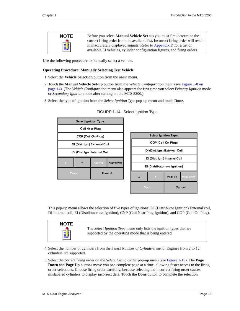
3. Select the type of ignition from the Select Ignition Type pop-up menu and touch Done.
This pop-up menu allows the selection of five types of ignitions: DI (Distributor Ignition) External coil, DI Internal coil, EI (Distributorless Ignition), CNP (Coil Near Plug Ignition), and COP (Coil On Plug).
4. Select the number of cylinders from the Select Number of Cylinders menu. Engines from 2 to 12 cylinders are supported.
5. Select the correct firing order on the Select Firing Order pop-up menu (see Figure 1-15). The Page Down and Page Up buttons move you one complete page at a time, allowing faster access to the firing order selections. Choose firing order carefully, because selecting the incorrect firing order causes mislabeled cylinders to display incorrect data. Touch the Done button to complete the selection.
NOTE Before you select Manual Vehicle Set-up you must first determine the correct firing order from the available list. Incorrect firing order will result in inaccurately displayed signals. Refer to Appendix D for a list of available EI vehicles, cylinder configuration figures, and firing orders.
NOTEThe Select Ignition Type menu only lists the ignition types that are supported by the operating mode that is being entered.
FIGURE 1-14. Select Ignition Type
MTS 5200 Engine Analyzer Page 18

Chapter 1 Introduction to the MTS 5200
6a. For engines with EI: The Lead Hook-up screen appears on the tester display. Follow the lead connection information on the display to connect the tester to the vehicle. Press the Continue button to begin testing.
6b.For engines with DI: The tester presents the Display Mode screen. Press the Lead Help button for lead connection information. Begin testing once the leads have been properly connected.
Last Vehicle Selection
When you select Last Vehicle on the Vehicle Configuration screen (see Figure 1-8 on page 14), the system recalls the last vehicle from the tester memory as described at the bottom of the Vehicle Configuration screen.
Use the following procedure to select the Last Vehicle for diagnosis.
Operating Procedure: Selecting Last Vehicle
1. Select the Vehicle Selection button from the Main menu.
2. Select the Last Vehicle button from the Vehicle Configuration menu. This button is also available from the Vehicle Configuration menu the first time you select Primary Ignition mode or Secondary Ignition mode after turning on the MTS 5200.
3a. For engines with EI: The Lead Hook-up screen appears on the tester display. Follow the lead connection information on the display to connect the tester to the vehicle. Press the Continue button to begin testing.
3b.For engines with DI: The tester presents the Display Mode screen. Press the Lead Help button for lead connection information. Begin testing once the leads have been properly connected. This screen is only seen when selecting Last Vehicle from ignition mode.
FREEZE
The Freeze button is available any time the MTS 5200 is collecting data in any of the display modes. The Freeze button stops the collection of live data and freezes the signal on the display, allowing you to analyze the frozen signal. Once the Freeze button is pressed, you are able to perform additional functions, such as Save the frozen signal to memory.
FIGURE 1-15. Select Firing Order
MTS 5200 Engine Analyzer Page 19

Chapter 1 Introduction to the MTS 5200
Run
The Run button returns you to the active data collection mode.
Save
Select the Save button to save the frozen image on the display.
When the Save button is selected, the Edit Notes screen is displayed. Here you are allowed to enter notes specific to the data you are saving by using the electronic keyboard provided on the touch screen display. The vehicle identification information is automatically stored with your entered notes, and the MTS 5200 gives your saved data a filename related to the used operating mode. When you press Enter on the electronic keyboard or on the keypad, you return to the same mode from which you saved the data. You may view your saved data at a later time using the Recall feature or the File Manager feature in the Analyzer Utilities mode.
Images are saved to non-volatile memory when the Save button is pressed.
Recall
Select the Recall button to recall a previously saved waveform.
Pressing the Recall button brings up a list box that displays the file names and time stamps of the saved screen captures that apply to the current operating mode. Selecting a file from this list displays the screen capture.
Upload
You can upload saved bitmap files to you PC directly from your MTS 5200 using the File Transfer Utility. See Chapter 14 for a description of the FTU and the upload procedures.
NOTEIn order to activate the Save button, you must first freeze the screen by pressing the Freeze button.
NOTEIn order to activate the Recall button, you must first freeze the screen by pressing the Freeze button.
NOTE Only screen captures (.bmp) and FCI Test Log (.prt) files can be uploaded to the PC. Uploading requires the File Transfer Utility application, Shop Foreman Pro, or the TechView Pro application.
MTS 5200 Engine Analyzer Page 20

Chapter 1 Introduction to the MTS 5200
POWERING DOWN THE TESTER
The tester can be powered down at any time by pressing the ON/OFF button. Hold the ON/OFF button down until a beep is heard, then release the button, and the tester begins the power down process. During power down the tester saves operating mode settings and the selected vehicle to permanent memory.
MTS 5200 Engine Analyzer Page 21

2. USING THE 4-CHANNELOSCILLOSCOPE
INTRODUCTIONThe 4-Channel Oscilloscope is an easy-to-use and versatile tool that allows access to any automotive computer-controlled circuit. Once you are familiar with the oscilloscope layout and features, you can take full advantage of the most powerful tool in its class.
All touch screen display buttons, keypad buttons, and test lead ports are clearly labeled on the front of your MTS 5200. (See Figure 1-2 on page 6 for an annotated illustration of the MTS 5200.) Use the touch screen display (or, where available, the keypad buttons) to access all the features on the oscilloscope. You can easily adjust the oscilloscope to a wide variety of voltage ranges and sampling speeds in order to view the most detailed waveforms. You can view up to four waveforms simultaneously (see the example in Figure 2-1), allowing you to see the important relationship between different automotive input and output signals.
FIGURE 2-1. Oscilloscope Main Menu Displaying Four Active Channels
MTS 5200 Engine Analyzer Page 22

Chapter 2 Using the 4-Channel Oscilloscope
CONNECTING LEADSBefore using the oscilloscope, connect your leads to the color-coded ports positioned above the touch screen display on the face of the MTS 5200. The oscilloscope leads are shielded to eliminate noise and interference from the vehicle. Be sure to connect the shielded ground leads for all oscilloscope channels that you are using.
Once the MTS 5200 is turned on and the oscilloscope selected, you can view a connecting lead diagram for an example configuration by touching the Lead Help button (see Figure 2-2). Lead Help displays an example of a single channel configuration or a multiple channel configuration, depending on how many channels you have turned on.
WARNING! The MTS 5200 is not intended for testing 110V, AC electrical circuits. Do not plug the leads into an electrical wall socket. Damage to the tester or personal injury may occur.
NOTEInspect shielded ground leads, and replace any that are damaged or have exposed wires. They are dangerous and can result in poor readings.
CAUTION
CAUTION! • Route the leads so that they do not get caught in the fan.
• Be sure to use correct wire probing procedures to prevent damage to the connectors or wires in the circuit under test.
VEHICLEGROUND
FIGURE 2-2. Connecting Leads for Two Channels
MTS 5200 Engine Analyzer Page 23

Chapter 2 Using the 4-Channel Oscilloscope
PATTERN DISPLAYOnce in oscilloscope mode, you have three options for pattern display:
• If you know the component signal you are testing, use the settings from the previous use of the oscilloscope, which is automatically displayed, and manually enter any necessary changes. This Manual Setup is the default display mode.
• If you do not know the signal characteristics of the component you are testing or if you do not wish to manually make adjustments, choose Component Selection for automatic oscilloscope setup.
• If you have properly connected the oscilloscope leads but cannot see a waveform on the touch screen display, select Signal Finder to allow the oscilloscope to find the signal and display it for you.
Any time you are viewing a signal on the oscilloscope, you have the option of freezing the signal on the touch screen display and saving it to memory. Refer to Chapter 1 of this manual for more information.
MANUAL SETUP
When initializing the 4-Channel Oscilloscope, the settings from the previous use are restored and ready for use. You do not need to select any setup button to continue using these settings. This Manual Setup is the default display mode, and you can immediately begin to make changes to your existing oscilloscope settings by simply touching the desired buttons. Manual Setup of the oscilloscope is most often used when you are familiar with the signal characteristics.
COMPONENT SELECTION
When you choose Component Selection, the oscilloscope automatically configures itself for the vehicle component you designate. After touching the Component Selection button on the touch screen display, you see a menu of vehicle component categories from which to choose (see Figure 2-3). These include:
• Actuators
• Current Waveforms
• Distributor
• Electrical
• Fuel Injectors
• Ignition
• Sensors
• Pressure/Vacuum
Within each of these categories you must choose specific components to view. Refer to Appendix E for a list of the components available within each category. Based on your selection, the oscilloscope automatically sets the scaling, trigger type, trigger level, time base, and coupling for the expected signal.
MTS 5200 Engine Analyzer Page 24

Chapter 2 Using the 4-Channel Oscilloscope
Component Selection determines the oscilloscope channel(s) to be used. Be sure your leads are correctly connected to the appropriate channels. Channel 1 is used for individual signals (such as TPS Voltage) while Channels 1 and 2 are used for multiple signals displayed simultaneously. Secondary Ignition pattern and Sync pattern are routed to Channels 1 and 2.
Current Waveforms
When you select Current Waveforms, select the desired current probe test: Fuel Pump, Primary Ignition, High Current Probe, and Low Current Probe. The last two are generic measurements and configure the scope to measure in units of amperage. Selecting them causes the Volts/Div adjustment to change to Amps/Div. Fuel Pump and Primary Ignition are used with Low Current Probe.
Vacuum/Pressure
When you select Vacuum/Pressure, select the desired Vacuum Probe or Pressure Transducer setup: AC Vacuum, DC Vacuum, AC/DC Vacuum/Sync, AC Vacuum/Sync, Pressure, Pressure/Sync. These selections configure the scope to measure in units of pressure. The type of pressure units can also be selected in the Units of Measure utility screen.
When a Component Selection that displays AC Vacuum is selected (AC Vacuum, AC/DC Vacuum/Sync, AC Vacuum/Sync), a filter can be applied to the AC Vacuum trace if needed. To Select the AC Vacuum filter, press the Menu keypad button to activate the AC Vacuum Filter list box. This filter works just like the Smoothing function in the Vacuum Waveform mode (see Figure 2-4).
FIGURE 2-3. Component Selection Button and Pop-Up Screen
ComponentSelectionButton
MTS 5200 Engine Analyzer Page 25

Chapter 2 Using the 4-Channel Oscilloscope
Example Waveform
After you have selected a specific vehicle component, press the Freeze button and the Example Waveform button appears.
Example Waveform is only available in the Freeze display mode and provides a sample of a known good waveform of the selected component (see the example in Figure 2-5). While viewing the example waveform, you have the options of recalling a previously saved waveform, returning to your frozen waveform, or returning to view live data (by touching Run).
FIGURE 2-4. AC Vacuum Filter Selection
FIGURE 2-5. Example Waveform Display(Peak ‘n’ Hold Fuel Injector)
MTS 5200 Engine Analyzer Page 26

Chapter 2 Using the 4-Channel Oscilloscope
SIGNAL FINDER
If you have correctly configured the oscilloscope but see no waveform on the touch screen display, Signal Finder provides a quick and easy way to find the signal and display it. Signal Finder examines the input signal and automatically adjusts the settings for your selected channels in order to display the signal. Be sure that the channel is ON and the test leads are connected to the correct test port.
Signal Finder adjusts the Volts/Div, Ground Offset, and Trigger Level settings to the signal.
DEFAULT SETUP
The Default Setup button returns all of the scope settings back to the factory default settings.
CHANNEL CONTROLSThe oscilloscope has four separate channels that can display data simultaneously.
The channel buttons are located in the top left corner of the touch screen display. Touching a channel button gives you access to the settings specific to that individual channel, including the ability to turn the channel on or off. As soon as you turn a channel on, the signal being received is automatically displayed and clearly identified by the channel number (as in Figure 2-6 for Channel 1: ) on the left side of the signal display area.
Some settings are within the channel setup menu and may require you to select a specific channel button before changing the setting. A summary of each channel setting is shown beneath the signal display area.
Touch Done when you have completed changes for an individual channel setting. You are returned to the normal oscilloscope display mode, where the Volts/Div settings of all four oscilloscope channels are clearly shown beneath the signal display area (see Figure 2-6). The status displays either OFF or the existing Volts/Div setting.
NOTEThe Trigger Edge, Trigger Mode, Trigger Source, and Trigger Position settings are not adjusted but set to default values.
1
MTS 5200 Engine Analyzer Page 27

Chapter 2 Using the 4-Channel Oscilloscope
VOLTS/DIVISION
The Volts/Div setting is channel specific, and adjustment buttons are available on each individual channel setup menu. Volts/Div is most frequently used when fine tuning a signal for detail or comparing multiple signal types simultaneously. To change the Volts/Div setting, use the touch screen display buttons or the and keypad buttons below the screen. The voltage level is adjustable from 0.05 to 50.00 volts/div, and your change in voltage setting is seen immediately. The Volts/Div setting is clearly shown beneath the signal display area (see Figure 2-6).
Some Component Selections cause the scaling to change to units other than volts. In addition, English or metric units can be changed in the Units of Measure utilities screen.
OFFSET
Adjusting the Offset changes the vertical position of an individual signal on the touch screen display. The Offset adjustment buttons are available on each individual channel setup menu and are accessed by touching the channel button of the channel to be adjusted. To change the offset setting, use the touch screen display buttons or the and keypad buttons below the screen.
This feature is most frequently used when viewing multiple signals simultaneously. The channel offset can be adjusted to ±4 divisions of the screen at increments of 0.25 of a division.
FIGURE 2-6. Channel Setup Mode (Fuel Injector Voltage)
Channel SettingsSummary ofChannelSettings
⎨⎧⎩
MTS 5200 Engine Analyzer Page 28

Chapter 2 Using the 4-Channel Oscilloscope
AC/DC COUPLING
Selecting the correct type of coupling mode for your signal is important for accurate testing. The signal coupling buttons are available on each individual channel setup menu and are located on the left side of the touch screen display. ‘
DC Coupling
DC Coupling mode displays both the AC and DC components of the signal. This is the default setting for all four oscilloscope channels. The setting of your signal coupling is displayed at all times beneath the signal display area next to the channel’s Volts/Div information.
FIGURE 2-7. Channel Setup Menu and Offset Adjustment(Fuel Injector Voltage)
Offset Adjustment
FIGURE 2-8. Channel 1 Setup Menu with AC/DC/GND Buttons(O2 Sensor Voltage)
⎨⎧⎩
Coupling Buttons(AC/DC/Gnd)
MTS 5200 Engine Analyzer Page 29

Chapter 2 Using the 4-Channel Oscilloscope
AC Coupling
AC Coupling mode displays only the AC component of the signal under examination and is only supported for Channels 1 and 2. The status of your signal coupling is displayed at all times beneath the signal display area next to the channel’s Volts/Div information.
Ground Coupling
Ground Coupling mode ties the internal A/D (analog to digital) input to ground. Once selected, Ground Coupling is used to verify the channel’s ground position and to adjust the waveform trace. The status of your signal coupling is displayed beneath the signal display area at all times.
FIGURE 2-9. DC Coupling (Fuel Injector Voltage)
FIGURE 2-10. AC Coupling (Radiator Fan Current)
MTS 5200 Engine Analyzer Page 30

Chapter 2 Using the 4-Channel Oscilloscope
TIME/DIVISION
The Time/Div control is always available for adjustment and is consistently located in the lower left corner of the display. This control determines what length of time is being viewed on the display. Adjustments can be made using the touch screen display buttons or the and keypad buttons below the screen. Time/Div is adjustable from units of 20 seconds/div to 20 microseconds/div, and your change in Time/Div is seen immediately.
The Time/Division selection that you use is dependent on the type of waveform you are looking at and the characteristics of the waveform you wish to view.
When viewing a waveform with a high frequency (such as a Mass Air Flow sensor), a fast Time/Div setting is used. When viewing a voltage trace or waveform with a slow frequency or voltage change (such as an O2 sensor), a slow Time/Div setting is used.
In some cases viewing a waveform at too slow a Time/Div setting can result in frequency distortion (aliasing) or missing information. As you slow the Time/Div setting, you increase the time between samples, which allows data to be missed and not displayed.
For example, if you display 3 or 4 cycles of an injector firing at a slow Time/Div setting, the slower sample rate might miss the injector’s spike (inductive kick) or display it at a lower amplitude. If this occurs, Glitch Capture can be used to increase the sample rate and prevent missing data. See “Glitch Capture” on page 36.
NOTETime/Div is not adjustable for each individual channel. Any change in the Time/Div settings affects all displayed signals.
FIGURE 2-11. Time/Division Selection(Ch 1 - Primary Ignition Voltage, Ch 2 - Primary Ignition Current)
Time/DivisionSetting
MTS 5200 Engine Analyzer Page 31

Chapter 2 Using the 4-Channel Oscilloscope
TRIGGER SETUPThe MTS 5200 has a set of trigger controls that determine the exact instant the trace begins the sweep across the screen. If a trigger is set at a specific voltage level, and the signal being sampled achieves that trigger level voltage, then the MTS 5200 displays the signal. When triggering, a T appears in the small box at the left of the trigger settings box at the bottom of the touch screen display.
While viewing live data, you can access all trigger properties through the Trigger Setup touch screen display button to the left of the signal display area. The 4-Channel Oscilloscope has the ability to use any one of four channels as the trigger source.
TRIGGER SOURCE
Trigger Source allows you to choose from a wide variety of sources—Channel 1, Channel 2, Channel 3, Channel 4, RPM, Secondary 1, Secondary 2, Primary, Expansion 1, and Expansion 2.
The trigger source being used by the oscilloscope is displayed on the touch screen display button as well as in the trigger settings box displayed at the bottom of the touch screen display. The trigger source button is located in the top left corner of the Trigger Setup menu.
NOTE If the trigger is from the RPM, Secondary 1, Secondary 2, Primary, Expansion 1, or Expansion 2 connection, make sure that sources are connected to the correct inputs.
FIGURE 2-12. Active Trigger Indicator in Trigger Settings Box
TriggerIndicator
FIGURE 2-13. Location of the Trigger Setup Button(Primary Ignition Voltage)
Trigger SetupButton
MTS 5200 Engine Analyzer Page 32

Chapter 2 Using the 4-Channel Oscilloscope
Once the Source button is selected, a Select Trigger Channel pop-up menu appears with all of the possible trigger source options. Your new choice for the trigger source is displayed on the trigger source button as well as in the trigger settings box (see Figure 2-14).
TRIGGER TYPE
There are four different types of triggers to choose from when viewing a signal—Auto, Normal, Single Shot, and Free Run. Trigger type is available in the Trigger Setup menu. When the Trigger Type button is selected from the upper left corner of the Trigger Setup menu, a pop-up menu appears with the four trigger types to choose from. Your new trigger type is displayed on the Trigger Type button as well as in the trigger settings box below the signal display area.
FIGURE 2-14. Trigger Source Button and Select Trigger Channel Pop-Up Menu
Trigger SourceButton Trigger Settings Box
FIGURE 2-15. Trigger Setup Menu and Select Trigger Type Box Pop-Up Menu
MTS 5200 Engine Analyzer Page 33

Chapter 2 Using the 4-Channel Oscilloscope
Auto (Automatic) Trigger
Auto trigger is the easiest type of trigger to use when viewing an automotive signal. The MTS 5200 displays a signal that meets the trigger level at the trigger position. If the signal does not meet the trigger level condition, the MTS 5200 automatically displays any signal that is received as if it were in Free Run mode (see “Free Run” on page 34). Once you see the signal, you can change the trigger level value to capture the waveform. Automatic trigger is the default trigger type on select vehicle components when using the Component Selection procedure to view a waveform such as Idle Air Control. Your last trigger type settings are saved in tester memory.
Normal Trigger
Normal trigger is a common trigger type and requires that you know the characteristics of the signal you are trying to display. The MTS 5200 displays a signal that meets the trigger level at the trigger position. If the signal does not meet the trigger level condition, the MTS 5200 does not display a signal. If you lose the trigger condition while viewing a signal, the signal display area freezes and remains frozen until the signal reaches the trigger level. Normal trigger is the default trigger type on select vehicle components when using the Component Selection procedure to view a waveform such as fuel injector. Your last trigger type settings are saved in tester memory.
Single Shot Trigger
Single Shot trigger is used when you want to capture a certain characteristic of a known signal. If the signal under examination does not reach your trigger threshold setting, the MTS 5200 does not display any signal. Once you set up the trigger level and trigger position, arm the oscilloscope as follows:
Procedure: Arming the Oscilloscope
1. Select Single Shot from the Trigger Type menu in Trigger Setup mode.
2. Make your desired adjustments to Trigger Level, Trigger Position, Trigger Source, and Trigger Edge.
3. Touch Done to exit the Trigger Setup mode.
4. Press the Arm button, which appears below the Component Selection button.
Once the Arm button is pressed, the MTS 5200 waits to capture a single frame of the waveform that meets your trigger conditions. The MTS 5200 displays the signal characteristic that meets your requirements and freezes the signal display area. Your last trigger type settings are saved in tester memory.
Free Run
Free Run trigger type is, in fact, a mode that eliminates the trigger function. In Free Run the MTS 5200 displays any signal that it receives. Free Run is generally used when viewing slower time base signals such as the Throttle Position Sensor signal. Free Run is the default trigger type on select vehicle components when using the Component Selection method to view a waveform such as TPS. Your last trigger type settings are saved in tester memory.
TRIGGER LEVEL
Trigger Level determines the height of the signal that must be met for the MTS 5200 to trigger and display the acquired signal. You can adjust the height of the trigger level by using the and touch screen display buttons located beneath the trigger source and trigger type buttons in Trigger Setup mode. Trigger Level is
MTS 5200 Engine Analyzer Page 34

Chapter 2 Using the 4-Channel Oscilloscope
also adjustable using the push buttons when in Trigger Setup mode. The voltage height of the Trigger Level is displayed beneath the touch screen display adjustment buttons and is also displayed beneath the signal display area at all times. The Trigger Level Indicator (designated by a caret: ) on the right side of the signal display area signifies the trigger level’s position on the actual display.
TRIGGER POSITION
Trigger Position determines the horizontal position where the trigger level condition is met. The Trigger Position can be moved to any horizontal location on the signal display area in increments of 1%, depending on the part of the signal you want to view. The Trigger Position (%) buttons are displayed to the left of the signal display area when in Trigger Setup mode and can be changed using the and touch screen display buttons. The Trigger Position Indicator (designated by a T: ) is at the bottom of the signal display area.
TRIGGER EDGE
Trigger Edge works in conjunction with the Trigger Level. Any signal that meets the Trigger Level condition and your choice of trigger edge (Rising or Falling) is displayed at the Trigger Position. The Rising Edge and Falling Edge buttons are available on the Trigger Setup menu as touch screen display buttons. If Rising Edge is selected, only a rising signal that reaches the trigger level and transitions to that voltage from a lower voltage meets the trigger conditions and is displayed. A Falling Edge trigger works just the opposite.
NOTETrigger adjustment controls are not available in Free Run trigger.
<
T
FIGURE 2-16. Rising Edge Trigger(Idle Air Control)
Trigger EdgeButtons
MTS 5200 Engine Analyzer Page 35

Chapter 2 Using the 4-Channel Oscilloscope
GLITCH CAPTURE Glitch Capture enables you to capture and display very short duration voltage spikes. The Glitch button is located on the Main menu. Once Glitch is selected, the MTS 5200 automatically sets up the Glitch Capture mode. The primary difference between Normal scope mode and Glitch Capture operation is the active sampling rate. In Normal scope mode, the sampling rate changes as the Time/Div adjustment is changed. In Glitch Capture mode, the sampling rate is always 6 megasamples/sec.
FREEZEFor a discussion of the Freeze mode, see “Freeze” on page 19.
SNAPSHOTFor a discussion of the Snapshot mode, see “Snapshot” on page 153.
NOTEGlitch Capture is only available on Channels 1 and 2. Channels 3 and 4 are disabled when Glitch is turned on.
MTS 5200 Engine Analyzer Page 36

Chapter 2 Using the 4-Channel Oscilloscope
CURSORSIn the oscilloscope live mode, Freeze mode, and Playback mode you can enable two horizontal and two vertical cursors to make precise measurements of waveforms displayed on the grid. You can turn the cursors on and off, and lock them so that they move together to maintain their relative delta measurements.
The active cursors are displayed as solid horizontal and vertical lines extending the entire height or width of the waveform display area. The inactive cursors are displayed as dashed horizontal and vertical lines.
When the cursors are activated, a Cursor Information Box appears at the bottom of the display showing the delta measurement between the cursors. Cursor information appears in the units of measure that are applicable to the channel that is selected for cursor measurement (i.e., the same units that are displayed in the Time/Div and Volts/Div selection boxes).
Because each oscilloscope channel can potentially be set to different Volt/Div settings, the vertical cursors can only display the units of measure for one channel at a time. In other words, the information in the Cursor Information Box is only applicable to the selected cursor channel.
If a screen is saved while the cursors are displayed, the cursors and cursor information are saved as part of the screen. Full cursor operation is also available when playing back a scope snapshot.
FIGURE 2-17. Cursor Menu from Main Menu
Cursor ChannelSelection
Active Cursors
Inactive Cursors
Cursor InformationBox
MTS 5200 Engine Analyzer Page 37

Chapter 2 Using the 4-Channel Oscilloscope
CURSOR CONTROLS
Cursor Button
A Cursor button appears on the oscilloscope Main menu, Freeze menu, and Playback menu.
When the Cursor button is pressed on the Main menu, Freeze menu, or Playback, an appropriate cursor menu appears. In the cursor menu there are four sections specific to cursor operation: Cursor Select, Lock Cursors, Cursor A/B, and Cursor Channel.
Cursor Select Button
When the Cursor Select button is pressed, the Cursor Selection list box appears.
The following cursor options are available:
• Cursors Off: No cursors appear on the display screen.
FIGURE 2-18. Cursor Button on Oscilloscope Main Menu
FIGURE 2-19. Cursor Selection List Box
MTS 5200 Engine Analyzer Page 38

Chapter 2 Using the 4-Channel Oscilloscope
• All Cursors: Both the horizontal and vertical measurement cursors appear on the display screen.
• Horizontal Cursors: Only the two horizontal measurement cursors appear on the display screen.
• Vertical Cursors: Only the two vertical measurement cursors appear on the display screen.
The OK button activates the cursor selection (whether cursors have been turned on or off), and the Cancel button causes the list box to disappear with no change in cursor selection.
Lock/Unlock Cursor Button
This button toggles between locking and unlocking the horizontal cursors and the vertical cursors together so that they retain their delta time, volts, etc. settings as they are adjusted.
Cursor A/B Button
This button toggles between one set of active cursors and the other. Only one horizontal and one vertical cursor can be active at a time. Active cursors appear as solid lines and inactive cursors are dashed lines.
Cursor Channel Selection
At the top left of the cursor menu are Cursor Channel selection buttons for each of the four scope channels. These buttons allow you to select the channel that the cursors will be scaled to. Channels that are not turned on are shaded and cannot be selected.
Selecting a cursor channel scales the units of measure to the selected channel. The units of measure and the selected cursor channel are displayed in the Cursor Information Box at the bottom of the screen.
CURSOR MOVEMENT
The four arrow keys on the MTS 5200 keypad control the movement of the cursors while in the cursor menu. The up/down arrows move the active vertical measurement cursors, and the left/right arrows move the active horizontal measurement cursors. While in the cursor menu, the keypad arrows are dedicated to cursor adjustment only.
FIGURE 2-20. Cursor Channel Selection and Cursor Menu
Cursor Channel
Cursor ChannelUnits of Measure
Selection Buttons
in the CursorInformation Box
Indicator in the Cursor InformationBox
Cursor Menu
MTS 5200 Engine Analyzer Page 39

Chapter 2 Using the 4-Channel Oscilloscope
ENGINEERING MODEEngineering Mode is an advanced oscilloscope feature that allows you to select input sources other than one of the four regular oscilloscope channels (see Table 2-1, “Engineering Mode Inputs”).
To activate the Engineering Mode, select the desired channel to change (Channels 1, 2, 3, or 4). Turn the channel off with the OFF button, then touch the ON button twice to display the Select Channel Source list box. To change back to the oscilloscope channel or to a different engineering channel source, re-enter Engineering Mode and select the oscilloscope channel. When you power down or press the Default Setup button, all Engineering Mode selections default to the proper oscilloscope channel.
Table 2-1: Engineering Mode Inputs
SOURCE INPUT DESCRIPTION
RPM SYNC Displays sync signal from the RPM Probe.
Secondary 1 SEC IGN Displays signals from the single secondary probe or the red Secondary EI leads.
Secondary 2 SEC IGN Displays signals from the black Secondary EI leads.
Primary PRI IGN Displays signals from the primary ignition lead.
Expansion 1 AUXILIARY Displays AC signal from the Vacuum Probe.
Expansion 2 AUXILIARY Displays DC signal from the Vacuum Probe or the signal from the Pressure Transducer.
MTS 5200 Engine Analyzer Page 40
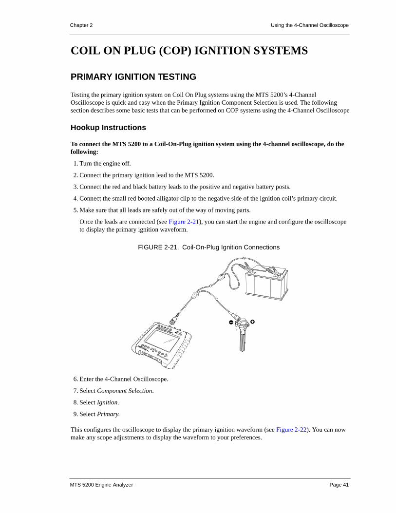
Chapter 2 Using the 4-Channel Oscilloscope
COIL ON PLUG (COP) IGNITION SYSTEMS
PRIMARY IGNITION TESTING
Testing the primary ignition system on Coil On Plug systems using the MTS 5200’s 4-Channel Oscilloscope is quick and easy when the Primary Ignition Component Selection is used. The following section describes some basic tests that can be performed on COP systems using the 4-Channel Oscilloscope
Hookup Instructions
To connect the MTS 5200 to a Coil-On-Plug ignition system using the 4-channel oscilloscope, do the following:
1. Turn the engine off.
2. Connect the primary ignition lead to the MTS 5200.
3. Connect the red and black battery leads to the positive and negative battery posts.
4. Connect the small red booted alligator clip to the negative side of the ignition coil’s primary circuit.
5. Make sure that all leads are safely out of the way of moving parts.
Once the leads are connected (see Figure 2-21), you can start the engine and configure the oscilloscope to display the primary ignition waveform.
6. Enter the 4-Channel Oscilloscope.
7. Select Component Selection.
8. Select Ignition.
9. Select Primary.
This configures the oscilloscope to display the primary ignition waveform (see Figure 2-22). You can now make any scope adjustments to display the waveform to your preferences.
FIGURE 2-21. Coil-On-Plug Ignition Connections
MTS 5200 Engine Analyzer Page 41

Chapter 2 Using the 4-Channel Oscilloscope
Primary vs. Secondary
Primary and secondary ignition waveforms are almost mirror images of each other (see Figure 2-23). However, there are two major differences between the primary ignition waveform and the secondary ignition waveform.
• The primary ignition circuit operates at a much lower voltage levels than does the secondary ignition circuit.
• The firing peak of the primary ignition circuit is not as sensitive as the secondary firing peak to changes in engine load or secondary resistance.
Other than these two differences, diagnosis of the primary ignition waveform can be treated the same as the diagnosis of a secondary ignition waveform.
See “Component Selection” on page 24 for a description of using component selection to view secondary ignition signals in the scope.
FIGURE 2-22. COP Primary Ignition Waveform
FIGURE 2-23. COP Primary and Secondary Ignition Waveforms
Primary
Secondary
MTS 5200 Engine Analyzer Page 42

Chapter 2 Using the 4-Channel Oscilloscope
Primary Current Ramping
In addition to viewing the primary voltage, you can also display the primary circuit’s current waveform for additional diagnostic information (see Figure 2-24).
To display the primary circuit’s current waveform, do the following:
1. Connect the Low Current Probe to the Channel 2 and Ground port of the oscilloscope.
2. Clamp the Low Current Probe around the coil’s negative wire.
3. Turn the Low Current Probe on.
4. Turn Channel 2 on and adjust the channel setting to display the waveform properly.
FIGURE 2-24. Primary Circuit’s Current Waveform
Primary
Current Ramp
MTS 5200 Engine Analyzer Page 43

3. PRIMARY IGNITION
INTRODUCTIONThe Primary Ignition diagnostic test mode (see Figure 3-1) is an easy-to-use and versatile function that allows access to automotive ignition primary circuits. The MTS 5200 Primary Ignition mode is adjustable to a variety of cylinder configurations, voltage ranges, and primary ignition systems, and includes Single, Parade, Raster, Firing Volts Barchart, and Superimposed display modes.
FIGURE 3-1. Primary Ignition Mode
MTS 5200 Engine Analyzer Page 44

Chapter 3 Primary Ignition
CONNECTING FOR PRIMARY IGNITION
DISTRIBUTOR IGNITION SYSTEM (DI)
The Distributor Ignition system is the most common ignition system for early model year vehicles. DI systems use one coil that fires one spark plug at a time on the compression stroke only. Viewing the primary ignition pattern requires that you monitor the voltage signal on the negative side of the coil’s primary circuit and that you identify the trigger cylinder using the RPM probe. See Figure 3-2 for an example of a standard primary ignition hookup.
Connecting the Leads
To connect the leads for a standard DI Primary Ignition, use the following procedure:
1. Turn the engine off.
2. Connect the Sync Probe to the MTS 5200 and to the trigger cylinder. The default trigger cylinder is cylinder #1.
3. Connect the primary ignition lead to the MTS 5200.
4. Connect the red and black battery leads to the positive and negative battery posts.
5. Connect the small red booted alligator clip to the negative side of the ignition coil’s primary circuit.
6. Make sure that all leads are safely out of the way of moving parts.
7. Start the engine and begin testing.
COIL ON PLUG (COP) IGNITION SYSTEM
COP systems use one individual coil for each spark plug. Each coil is located directly on top of its spark plug and does not use any external spark plug wires. Each coil pack also has an independent primary circuit which must be tested individually.
TRIGGERCYLINDER
FIGURE 3-2. Primary Ignition Connection
MTS 5200 Engine Analyzer Page 45

Chapter 3 Primary Ignition
Connecting the Leads
Use the following guidelines to connect the leads for COP systems:
1. Engine off.
2. Remove the coil pack of the trigger cylinder (leave the coil pack connector connected).
3. Place a jumper spark plug wire from the coil pack to the spark plug that the coil pack was attached to.
4. Connect the Sync Probe to the MTS 5200 and to the jumper spark plug wire that was installed (select this cylinder as the trigger cylinder).
5. Connect the primary ignition lead to the MTS 5200.
6. Connect the red and black battery leads to the positive and negative battery posts.
7. Connect the small red booted alligator clip to the negative side of the primary circuit of the ignition coil under test.
8. Make sure that all leads are safely out of the way of moving parts.
9. Start the engine and begin testing.
NOTE When testing COP systems in this manner, only the cylinder under test is displayed on the display screen. To test other cylinders, move the primary lead to another coil.
FIGURE 3-3. Typical COP Primary Lead Connection
MTS 5200 Engine Analyzer Page 46

Chapter 3 Primary Ignition
PATTERN DISPLAYThe Display Mode (see Figure 3-4) allows you to select the type of pattern display of your choice. To change the display mode, touch the Display Mode button at the top left of the display screen, bringing up the Select Display Mode pop-up menu (Figure 3-4).
The Select Display Mode pop-up menu allows you to choose from different types of pattern displays, including Single Cylinder, Parade, Raster, Firing Volts Barchart, and Superimposed.
Once you have selected the display, touch the Done button to close the menu. The selected pattern display is now indicated in the Display Mode button.
CYLINDER SELECTION
The Cylinder Selection display will always be located on the lower edge of the display, allowing you instant access to turning off and on any cylinder(s) within a specific firing order. To operate, simply touch any combination of the Cylinder Selection buttons to hide or show the waveform of a specific cylinder (or group of cylinders). Cylinder Selection is always displayed in the selected firing order.
FIGURE 3-4. Display Mode and Select Display Mode Pop-Up Menu
Display Mode Button
Cylinder SelectionDisplay
MTS 5200 Engine Analyzer Page 47

Chapter 3 Primary Ignition
SINGLE CYLINDER
Single Cylinder display mode allows you to view the waveform characteristics of a single cylinder in the firing order (see Figure 3-5). By pressing the Cylinder Selection buttons at the bottom of the touch screen display, you have the ability to view each cylinder’s waveform individually. Only one cylinder is displayed at any one time.
FIGURE 3-5. Primary Single Cylinder Display
MTS 5200 Engine Analyzer Page 48

Chapter 3 Primary Ignition
PARADE
Parade display mode allows you to view the waveform of each cylinder in the firing order on a single screen, simultaneously. Selecting a cylinder from the Cylinder Selection buttons at the bottom of the touch screen display causes the MTS 5200 to display the selected cylinder behind the normal parade display in an enlarged format. Pressing the same cylinder button again causes the MTS 5200 to display the normal primary parade display. The Parade display is generally used to compare the waveforms of all cylinders in the firing order.
NOTEIf a single cylinder is selected from the Parade display, the time base selected is only for the main Parade portion of the pattern. The individual cylinder selected and displayed above the Parade pattern cannot be analyzed using the Time/Div settings for the rest of the display. To analyze a problem cylinder, choose the Single Cylinder display mode from the Display Mode menu and choose the appropriate Time/Div and Volts/Div settings.
FIGURE 3-6. Primary Parade Display
FIGURE 3-7. Cylinder Selection in Primary Parade Display
MTS 5200 Engine Analyzer Page 49

Chapter 3 Primary Ignition
RASTER
Raster display mode allows you to view the waveform of each cylinder in the firing order on a single screen, simultaneously. Selecting a cylinder from the Cylinder Selection buttons at the bottom of the touch screen display causes the MTS 5200 to hide or display the selected cylinder. You may choose to display any number of cylinders on the display but the MTS 5200 always takes into account the number of cylinders in the firing order and spaces the patterns so that all cylinders are displayed on a single screen. You may change the spacing between the cylinder waveforms using the Pattern Spacing touch screen button in the Setup menu. Pattern Spacing affects all cylinders in the firing order and is not specific to your selected cylinders.
FIGURE 3-8. Primary Raster Display
MTS 5200 Engine Analyzer Page 50

Chapter 3 Primary Ignition
SUPERIMPOSED
Superimposed display mode allows you to view the waveform of each cylinder in the firing order on a single screen, simultaneously. Each cylinder waveform is positioned beginning with the firing spike at the trigger position. The cylinder waveforms therefore overlap each other. Selecting a cylinder from the Cylinder Selection buttons at the bottom of the touch screen display causes the MTS 5200 to hide or display the selected cylinder. You may choose to display any number of cylinders on the display at any one time.
FIRING VOLTS BARCHART
Barchart display mode allows you to view the voltage levels of each cylinder in the firing order on a single screen. Each cylinder’s primary voltage is displayed in barchart format so it is easy to spot a cylinder voltage that does not compare with the others. All cylinders are displayed in the correct firing order at all times.
FIGURE 3-9. Primary Superimposed Display
FIGURE 3-10. Primary Firing Volts Barchart Display
Reset Button
MTS 5200 Engine Analyzer Page 51
Chapter 3 Primary Ignition
The Firing Volts Barchart displays a bar graph showing the primary voltage required for each cylinder. Live, Min (Minimum), Max (Maximum), and Avg (Average) values for each cylinder are displayed (see Figure 3-10). The numeric units are displayed in volts. The cylinders are listed in firing order sequence.
• The Live data value is the same data displayed in the barchart format.
• The Min value is the lowest voltage value recorded for that cylinder.
• The Max value is the highest voltage value recorded for that cylinder.
• The Avg value is the average voltage value recorded for that cylinder.
Pressing the Reset button resets the Min/Max/Avg data.
SETTINGS
VOLTS / DIVISION
To adjust the Volts/Div, touch the or buttons to set the proper voltage level. Voltage level is adjustable from 10V/div to 500V/div. You can immediately see the results of any voltage adjustments.
TIME / DIVISION
The Time/Div control is always available for adjustment and is consistently located in the lower left corner of the display screen. This control determines what length of time is being viewed on the display. Time/Div adjustments on the Primary Ignition display vary with the display mode selected and can range from 0.2 ms/div to 20ms/div. Whenever a particular display mode is selected (Parade, Raster, Single, Superimposed, or Firing Volts Barchart), the previously used Time/Div setting is displayed; however, you can change this adjustment at any time by using the or buttons.
NOTE Upon exiting and powering down the MTS 5200, the following user settings are saved for your convenience: Volts/Div, Time/Div, Trigger Position, and Ground Offset. Upon re-entering Primary Ignition mode, these return to their previous setting.
MTS 5200 Engine Analyzer Page 52

Chapter 3 Primary Ignition
SETUP BUTTON
The Setup button (see Figure 3-11) is part of the default set of controls for the MTS 5200 ignition modes.
Selecting the Setup button gives you access to the Trigger Position, Trigger Cylinder, and Ground Offset buttons (see Figure 3-12). These are described below.
Main Button
Once you have made your desired Setup changes, touch the Main button to return to the default set of controls on the Display Mode screen.
FIGURE 3-11. Setup Button
Setup Button
FIGURE 3-12. Functions Accessed by the Setup Button
Use Setupbutton to access these functions ⎨
MTS 5200 Engine Analyzer Page 53

Chapter 3 Primary Ignition
Trigger Position
Trigger Position (see Figure 3-13) enables you to move the primary ignition pattern to the left and right on the display. The button must be pressed before using the and buttons. The trigger position is designated by a and correlates to the position of the primary ignition firing spike. This setting can be changed in 5% increments between 10% (near the left edge of the display) and 90% (near the right edge of the display).
Trigger Cylinder
The Trigger Cylinder control enables you to change the trigger cylinder. The Sync Probe provides a cylinder reference signal when connected to the spark plug wire of the trigger cylinder. The trigger cylinder defaults to cylinder #1 but can be changed to any cylinder in the firing order. For example, cylinder #1 may be difficult to access or not operating properly. Regardless of the selected trigger cylinder, the primary ignition patterns are displayed the same (i.e., the Parade display shows the cylinders in the firing order with cylinder #1 on the left).
Ground Offset
The Ground Offset control allows the ground position and primary ignition pattern to be moved vertically on the display. The button must be pressed before using the and arrows. The ground position is designated by a on the left side of the signal display area. When you are viewing multiple channels, the Ground Offset does not affect individual cylinders.
NOTEThe Sync Probe must be connected to the selected trigger cylinder.
T
FIGURE 3-13. Trigger Position and Ground Offset Designators
Trigger Position Designator
Ground Offset Designator
G
MTS 5200 Engine Analyzer Page 54

Chapter 3 Primary Ignition
PATTERN SPACING
The MTS 5200 has a feature in the Raster Display mode that allows you to change the spacing between individual cylinder patterns. From the Primary Raster display screen, touch the Patt Space button. Notice that the Patt Space button becomes the Volts/Div button, and the Volts/Div adjustment box below the Patt Space button becomes the Pattern Space adjustment box. Use the and arrow keys to increase or decrease the amount of space between the cylinder patterns. When adjusting the pattern space between cylinders, the spacing affects all cylinders whether they are turned off or not. When finished, press the Volts/Div button to toggle the adjustment box back to Volts/Div and the Volts/Div button back to Patt Space.
LEAD HELP BUTTON
Touching the Lead Help button displays a graphic showing the proper connection of the leads to the primary ignition system.
SHOW VEHICLE BUTTON
The Show Vehicle button displays the selected vehicle information. See “Entering the Test Vehicle” on page 14 to change test vehicle information.
NOTE All adjustments for Volts/Div, Time/Div, Ground Offset, Trigger Position, and Pattern Spacing can be made using either the display buttons or the arrow keys on keypad located below the display.
FIGURE 3-14. Pattern Spacing
Pattern Spacing
MTS 5200 Engine Analyzer Page 55

Chapter 3 Primary Ignition
ACTIVE BUTTONS SUMMARY
PRIMARY IGNITION ACTIVE BUTTONS
Main Menu(for Single Cylinder, Parade, Raster, and Superimposed Display Modes)
Volts/Div Sets voltage scaling
Time/Div Sets time length being viewed on the display
Setup Accesses Setup functions
Main Returns from Setup menu to Main menu
Trig Pos (Time/Div) Moves trigger position left or right on screen(toggles with Time/Div)
Trig Cyl Selects cylinder to trigger on
Grd Offset (Volts/Div) Moves ground position up or down on screen(toggles with Volts/Div)
Patt Space (Volts/Div) Sets spacing between cylinder patterns (in Raster Display Mode only; replaces Show Veh.) (toggles with Volts/Div)
Freeze Freezes screen display
Run Continues live data display
Save Saves frozen screen to memory
Recall Recalls screen from memory
Lead Help Displays connection of MTS 5200 to vehicle
Show Veh. Displays selected vehicle information (from database)
Snap Shot Accesses the Snapshot functions
Cyl Help Displays cylinder configuration for selected vehicle
Barchart Menus (for Firing Volts Barchart Display Mode)Trig Cyl Selects cylinder to trigger on
Freeze Freezes screen display
Save Saves frozen screen to memory
Run Continues live data display
Lead Help Displays connection of MTS 5200 to vehicle
Snap Shot Accesses the Snapshot functions
Reset Resets all values for the barchart data
MTS 5200 Engine Analyzer Page 56

4. SECONDARY IGNITION
INTRODUCTIONThe Secondary Ignition diagnostic test mode is an easy-to-use and versatile function that allows access to automotive ignition secondary circuits. The MTS 5200 Secondary Ignition mode is adjustable to a variety of cylinder configurations, voltage ranges, and secondary ignition systems, and includes Single, Parade, Raster, Firing kV Barchart, Superimposed, and Power/Waste Comparison display modes. Available cylinder configurations include 2 to 12 cylinders.
SECONDARY IGNITION DI (DIST. IGN.)
TRIGGERCYLINDER
VEHICLEGROUND
FIGURE 4-1. Secondary Ignition Hookup
MTS 5200 Engine Analyzer Page 57

Chapter 4 Secondary Ignition
CONNECTING FOR SECONDARY IGNITION
DISTRIBUTOR IGNITION SYSTEM (DI)
The Distributor Ignition system is the most common ignition system for early model year vehicles. While the DI system has many mechanical parts, it is the easiest to connect to. It has one coil that fires one spark plug at a time on the compression stroke only. Viewing the secondary ignition pattern requires that you monitor the kilovolts (kV) coming from the coil using the single secondary ignition lead and that you identify the trigger cylinder using the RPM probe. Refer to Figure 4-1 for an example of a standard secondary ignition hookup.
Connecting the Leads
Use the following steps to connect the leads for a standard DI Secondary Ignition.
1. Turn the engine off.
2. Connect the Sync Probe to the MTS 5200 and to the trigger cylinder. The default trigger cylinder is cylinder #1.
3. Connect the single secondary ignition lead to the MTS 5200.
4. Connect the probe end of the single secondary ignition lead to the coil wire.
5. Connect the ground shield end of the single secondary ignition lead to a good vehicle ground.
6. Make sure that all leads are safely out of the way of moving parts.
7. Start the engine and begin testing.
ELECTRONIC IGNITION SYSTEM (DIS)
There are two fundamental differences between an electronic ignition (EI or DIS, direct or distributorless ignition system) and a conventional distributor ignition (DI):
• Fewer Moving Parts—By removing the distributor assembly, cap, and rotor, the EI (DIS) system uses fewer moving parts. Based on signals from several sensors, including a crankshaft position sensor, the vehicle’s on-board computer determines the best time to fire the spark plug.
• Multiple Ignition Coils—The EI (DIS) system replaces the single conventional coil with one double-ended ignition coil for every two cylinders. The multiple coils extend coil life by allowing for better coil saturation and longer cool-down times between firings for each coil.
The DI ignition system has one coil that fires one spark plug at a time on the compression stroke only. EI systems, on the other hand, have a dedicated double-ended coil for each pair of cylinders. Each coil is in series with two plugs and fires the two plugs simultaneously. Each of the paired cylinders, referred to as companion cylinders, are at opposite locations in the firing order—one cylinder is near top dead center of the compression stroke while the other is near top dead center of the exhaust stroke. Because one cylinder is always fired during the exhaust stroke and serves no useful purpose, it is called the waste spark. One crankshaft revolution later, that same cylinder is on the compression stroke and fires the power spark.
The polarity of the coil windings is fixed. One spark plug always fires in the forward direction (from the center to the outer electrode), and the companion cylinder always fires backwards (from the outer to the center electrode). Because of unique events happening in the combustion chamber for the two cylinders, the
MTS 5200 Engine Analyzer Page 58

Chapter 4 Secondary Ignition
firing voltage between forward and backward cylinders may be uneven. A firing kilovolt (kV) difference of as much as 30% can be seen between a forward and backward firing cylinder.
Companion cylinders can be determined by listing the first half of the engines firing order above the second half. Cylinder numbers directly above or below each other are companion cylinders.
The firing voltage required to bridge the gap of each spark plug is determined by the air gap in each cylinder’s secondary circuit (and related combustion chamber events). The sparks extinguish when the coil voltage becomes too low to maintain the spark, and the gaps become nonconducting. Increased resistance appears on the waveform as a slight rise in the spark line.
After the sparks extinguish, the remainder of the ignition coil energy is dissipated and displayed as a series of gradually diminishing oscillations resulting from unused available current flowing first in one direction and then the other. It appears on the waveform as a decreasing alternating voltage until the energy is dissipated.
The cylinder on the exhaust stroke requires very little of the available energy to fire the spark plug. This is displayed as a much lower kV firing line. The remaining energy is used as required by the cylinder on the compression stroke. This is displayed as a higher kV firing line. The same process is repeated when the cylinders reverse roles.
Spider Leads and Junction Box
EI (DIS) systems require each ignition wire to be connected to one of the secondary ignition probes. Refer to Figure 4-3 for required hardware.
Example: Firing order is 1-2-3-4-5-6First Half: 1-2-3
Second Half: 4-5-6Result: (1&4) (2&5) (3&6) are companion cylinders
FIGURE 4-2. EI System Coil Pack and Module Assembly
FIRING ORDER1-2-3-4-5-6
MTS 5200 Engine Analyzer Page 59

Chapter 4 Secondary Ignition
The EI (DIS) Lead Hook-up screen (see Figure 4-4) is displayed when an EI (DIS) vehicle is selected.
The EI (DIS) Hook-up screen displays the following information:
• Firing Order as selected from the Manual Vehicle Set-up or from the vehicle database.
• Connections for the red and black EI (DIS) lead set to the correct spark plug wires. This is done to separate the simultaneous power and waste spark events.
• Cyl Help button to display the cylinder configuration for the selected vehicle from the vehicle database.
• Connections for the EI (DIS) junction box and Sync Probe to the Engine Analyzer and vehicle.
• Connection for the Sync Probe to the trigger cylinder.
TESTER
EI (DIS) JUNCTION BOX
VEHICLEGROUND
FIGURE 4-3. EI (DIS) Hardware Requirements
TRIGGERCYLINDER
VEHICLEGROUND
Electronic Ignition (DIS) Lead Hook-UpFiring Order:1-3-4-2
Red Leads:1-3Black Leads:4-2
Note: Connect only the necessary Leads to the junction box
Continue
Cyl. Help
FIGURE 4-4. EI (DIS) Lead Hook-Up Screen
MTS 5200 Engine Analyzer Page 60

Chapter 4 Secondary Ignition
Pressing either the Enter button from the keypad or the Continue button on the screen closes the Lead Hook-Up menu and starts the secondary signal display.
Connecting the Leads
The MTS 5200 can display all cylinders at one time for vehicles with electronic ignition systems.
Use the following steps to connect the leads:
1. Engine off.
2. Connect Sync Probe to the trigger cylinder (default is cylinder #1).
3. Connect the junction box to the Sec IGN on the MTS 5200.
4. Connect the necessary EI leads to the junction box.
5. Connect red EI leads to the spark plug wires of the first half of the firing order.
6. Connect black EI leads to the spark plug wires of the second half of the firing order.
7. Connect black ground clamp to the vehicle ground.
8. Start the engine and begin testing.
COIL NEAR PLUG (CNP) IGNITION SYSTEMS
Coil Near Plug ignition systems use one coil for each cylinder. The coils are usually mounted in close proximity, usually on the valve cover, to the spark plug that it fires. A short spark plug wire connects the coil to its spark plug.
Connecting the Leads
Use the following guidelines to connect the leads for CNP systems:
• Connect the EI leads to the individual spark plug wires.
• Disregard red and black color coding.
• Only connect the necessary amount of EI leads to the junction box.
• Connect the Sync Probe to the trigger cylinder (default trigger cylinder is #1).
COIL ON PLUG (COP) IGNITION SYSTEMS
COP systems use one individual coil for each spark plug. Each coil is located directly on top of its spark plug and does not use any external spark plug wires.
NOTE The Sync Probe will only trigger on cylinder #1 or its companion cylinder. If the companion cylinder is used, the Trigger Cylinder can be changed in the software by selecting the Trig Cyl button located on the menu screen.
MTS 5200 Engine Analyzer Page 61

Chapter 4 Secondary Ignition
Connecting the Leads
Use the following guidelines to connect the leads for COP systems:
1. Engine off.
2. Remove the coil pack of the trigger cylinder (leave the coil pack connector connected).
3. Place a jumper spark plug wire from the coil pack to the spark plug that the coil pack was attached to.
4. Connect the Sync Probe to the MTS 5200 and to the jumper spark plug wire that was installed (select this cylinder as the trigger cylinder).
5. Connect the Single Secondary Probe to the jumper spark plug wire.
6. Start the engine and begin testing.
UNIQUE IGNITION SYSTEMS
Because ignition systems vary from manufacturer to manufacturer, the following sections provide descriptions of some unique ignition systems and their connection instructions.
Ford: Dual Plug Distributorless Ignition System
The Dual Plug (DP) LDR (low data rate) EI (DIS) uses one primary system and two complete secondary ignition systems.
This system consists of a crankshaft-mounted dual Hall effect sensor, two 4-tower DIS coil packs, two spark plugs per cylinder, an EI (DIS) module, and the Electronic Engine Control-IV (EEC-IV) module. It is used on the 2.3L 4-cylinder EFI Truck engine.
NOTE When testing COP systems in this manner, only the cylinder under test is displayed on the display screen. To test other cylinders, move the jumper spark plug wire and probes to another cylinder, remembering to set the trigger cylinder to the cylinder that is being tested.
FIGURE 4-5. Typical COP Secondary Lead Connection
MTS 5200 Engine Analyzer Page 62

Chapter 4 Secondary Ignition
Since this system uses eight spark plugs (two spark plugs per cylinder), two coil packs are required. Each coil pack contains two coils. Two coils are mounted on the right side of the engine, and two coils are mounded on the left side of the engine. These coils are known as the right and left coils. The right coils are numbered 1 and 2. They function during cranking and running. The left coils are numbered 3 and 4. Presently, they function only after the engine is running, not when the engine is cranking. The left coils are prevented from functioning when a signal, known as dual plug inhibit (DPI), is sent to the DIS module from the EEC-IV module.
Connecting the Leads
To view the secondary circuit on the right side of the engine (numbered 1 and 2) used during cranking and running:
1. Turn engine off.
2. Connect the Sync Probe to the right side coil pack cylinder #1 (default is cylinder #1).
3. Connect the red EI leads to the spark plug wires coming from the right side coil pack of first half of the firing order.
4. Connect the black EI leads to the spark plug wires coming from the right side coil pack of second half of the firing order.
5. Connect the necessary EI leads to the junction box.
6. Connect the black ground clamp of the junction box to vehicle ground.
7. Start engine and begin testing.
To view the secondary circuit on the left side of the engine (numbered 3 and 4) used after the engine is running:
1. Turn engine off.
2. Connect Sync Probe to the left coil pack cylinder #1 (default is cylinder #1).
3. Connect the red EI leads to the spark plug wires coming from the left side coil pack of first half of the firing order.
4. Connect the black EI leads to the spark plug wires coming from the left side coil pack of second half of the firing order.
5. Connect the necessary EI leads to the junction box.
6. Connect the black ground clamp of the junction box to vehicle ground.
7. Start engine and begin testing.
Ford: Multi-Strike Ignition System
On some Ford vehicles, the secondary ignition system fires two consecutive times when the vehicle RPM is at idle. The Multi-Strike disables when the engine speed is above a specified RPM. When measuring Ford vehicles with Multi-Strike ignition systems, the tester should sync when the Multi-Strike is disabled. This can be done by one of two ways:
NOTEWhen testing the Ford Dual Plug system (DP), only four plug wires can be viewed at one time.
MTS 5200 Engine Analyzer Page 63

Chapter 4 Secondary Ignition
• Raise the engine RPM above idle and then sync with the ignition system. To sync the tester on engines with a Multi-Strike ignition, raise and hold engine speed at 1500 RPM, then enter desired ignition mode.
• Disable the Multi-Strike system. Refer to the vehicle service manual for more information.
Connecting the Leads
1. Turn engine off.
2. Connect Sync Probe to cylinder #1or the companion cylinder to cylinder #1 (default is cylinder #1).
3. Connect red EI leads to the spark plug wires from the first half of the firing order.
4. Connect black EI leads to the spark plug wires from the second half of the firing order.
5. Connect the necessary EI leads to the junction box.
6. Connect black ground clamp of the junction box to vehicle ground.
7. Start engine and begin testing.
General Motors: Integrated Direct Ignition (IDI)
The electronic ignition module assembly integrates two ignition coils and an ignition module all attached to the under side of a die cast cover plate that is mounted directly above the spark plugs.
The secondary ignition can be monitored by removing the secondary conductor housing from the spark plugs and placing it on top of the head area. Using 4 spare known good spark plug wires, connect one end to each spark plug and the other end to each matching cylinder ignition coils.
Connecting the Leads
1. Turn engine off.
2. Connect Sync Probe to the trigger cylinder (default is cylinder #1).
3. Connect red EI leads to the spark plug wires of the first half of the firing order.
4. Connect black EI leads to the spark plug wires of the second half of the firing order.
5. Connect black ground clamp of the junction box to vehicle ground.
6. Start engine and begin testing.
FIGURE 4-6. Coil Pack Housing
MTS 5200 Engine Analyzer Page 64

Chapter 4 Secondary Ignition
Nissan: NAP-Z Ignition System
The NAP-Z Nissan Anti-Pollution System has the Electronically Concentrated Control System (ECCS) used on the Nissan pick-up truck, Stanza, and 200SX 4 cylinder models. The NAP-Z system uses two spark plugs per cylinder. The system is designed to fire both plugs under normal driving conditions but switches to firing only one plug when under heavy load in order to reduce engine noise.
Connecting the Leads
Two ignition coils are mounted at the right front corner of the engine compartment. The top ignition coil is the exhaust (EX) side coil, and the ignition coil just beneath it is the intake (IN) side of the coil. Both ignition coil wires connect to the distributor cap at one side. The distributor cap has 8 spark plug wires and 4 cap terminals facing towards the passenger side of the vehicle labeled I1, I3, I4, and I2, from top to bottom. These 4 spark plug wires connect to the engine. The other 4 caps terminals face towards the driver’s side of the vehicle and are labeled E1, E3, E4, and E2, from bottom to top. Rotor rotation is counterclockwise.
To view the secondary circuit on the exhaust side, connect the leads as follows:
1. Turn engine off.
2. Connect Sync Probe to the trigger cylinder (default is cylinder #1).
3. Connect single Secondary Ignition Probe to the EXHAUST Coil Wire.
4. Connect Ignition Probe Ground lead to vehicle ground.
To view secondary circuit on the intake side, connect the leads as follows:
1. Turn engine off.
2. Connect Sync Probe to the trigger cylinder (default is cylinder #1).
3. Connect single Secondary Ignition Probe to the INTAKE Coil Wire.
4. Connect Ignition Probe Ground lead to vehicle ground.
MTS 5200 Engine Analyzer Page 65

Chapter 4 Secondary Ignition
PATTERN DISPLAYThe Display Mode (Figure 4-7) allows you to select the type of pattern display of your choice. To change the display mode, touch the Display Mode button at the top left of the touch screen display, bringing up the submenu Select Display Mode (Figure 4-7). The Select Display Mode allows you to choose from several different types of pattern displays, including Single Cylinder, Parade, Raster, Superimposed, Firing kV Barchart, and Power/Waste Comparison. Once you have selected the display mode, touch the Done button to close the menu. The selected pattern display is now indicated on the Display Mode button.
CYLINDER SELECTION
The Cylinder Selection display is always located on the lower edge of the touch screen display, allowing you instant access to turning off and on any cylinder(s) within a specific firing order. To operate, simply touch any combination of the Cylinder Selection buttons to activate or deactivate the cylinder. The Cylinder Selection is always displayed in the selected firing order.
SINGLE CYLINDER
Single Cylinder display mode allows you to view the waveform characteristics of a single cylinder in the firing order. By pressing the Cylinder Selection buttons at the bottom of the touch screen display, you have the ability to view each cylinder’s waveform individually. Only one cylinder will be displayed at any one time.
FIGURE 4-7. Display Mode and Select Display Mode Pop-Up Menu
Display Mode Button
CylinderSelection Display
MTS 5200 Engine Analyzer Page 66

Chapter 4 Secondary Ignition
PARADE
Parade display mode allows you to view the waveform of each cylinder in the firing order on a single screen, simultaneously. Selecting a cylinder from the Cylinder Selection buttons at the bottom of the touch screen display causes the MTS 5200 to display the selected cylinder behind the normal parade display in an enlarged format. Pressing the same cylinder button again causes the MTS 5200 to display the normal secondary parade display. The Parade display is generally used to compare the waveforms of all cylinders in the firing order.
FIGURE 4-8. Secondary Single Cylinder Display
FIGURE 4-9. Secondary Parade Display
MTS 5200 Engine Analyzer Page 67

Chapter 4 Secondary Ignition
RASTER
Raster display mode allows you to view the waveform of each cylinder in the firing order on a single screen, simultaneously. Selecting a cylinder from the Cylinder Selection buttons at the bottom of the touch screen display causes the MTS 5200 to hide or display the selected cylinder. You may choose to display any number of cylinders on the display, but the MTS 5200 always takes into account the number of cylinders in the firing order and spaces the patterns so that all cylinders are displayed on a single screen. You may change the spacing between the cylinder waveforms using the Pattern Spacing touch screen button in the Setup menu. Pattern Spacing affects all cylinders in the firing order and is not specific to your selected cylinders.
NOTEIf a single cylinder is selected from the Parade display mode, the time base selected is only for the main parade portion of the pattern. The individual cylinder selected and displayed above the parade pattern cannot be analyzed using the Time/Div settings for the rest of the display. To analyze a problem cylinder, choose the Single Cylinder display mode from the Display Mode menu and choose the appropriate Time/Div and kV/Div settings.
FIGURE 4-10. Cylinder Selection in Secondary Parade Display Mode
MTS 5200 Engine Analyzer Page 68

Chapter 4 Secondary Ignition
SUPERIMPOSED
Superimposed display mode allows you to view the waveform of each cylinder in the firing order on a single screen, simultaneously. Each cylinder waveform is positioned beginning with the firing spike at the trigger position. The cylinder waveforms therefore overlap each other. Selecting a cylinder from the Cylinder Selection buttons at the bottom of the touch screen display causes the MTS 5200 to hide or display the selected cylinder. You may choose to display any number of cylinders on the display at any one time.
FIRING kV BARCHART
The Firing kV Barchart display mode allows you to view the voltage levels of each cylinder in the firing order on a single screen. Each cylinder’s secondary voltage is displayed in barchart format so it is easy to spot a cylinder voltage that does not compare with the others. All cylinders are displayed in the correct firing order at all times.
FIGURE 4-11. Secondary Raster Display
FIGURE 4-12. Secondary Superimposed Display
MTS 5200 Engine Analyzer Page 69

Chapter 4 Secondary Ignition
Touch the Display Mode button and choose Firing kV Barchart in the Select Display Mode pop-up menu (see Figure 4-13).
The Firing kV Barchart selection displays a bar graph (see Figure 4-14) showing the secondary voltage (kV) for each cylinder.
The cylinders are arranged in firing order sequence with the following values in kilovolts displayed below each cylinder barchart:
• The Live data value is the numeric equivalent of the data displayed in the barchart format.
• The Min (minimum) value is the lowest voltage value recorded for that cylinder.
• The Max (maximum) value is the highest voltage value recorded for that cylinder.
• The Avg (average) value is the average voltage value recorded for that cylinder.
Pressing the Reset button resets the Min/Max/Avg data.
FIGURE 4-13. Selecting Secondary Firing kV Barchart
FIGURE 4-14. Secondary Barchart Display
Reset Button
MTS 5200 Engine Analyzer Page 70
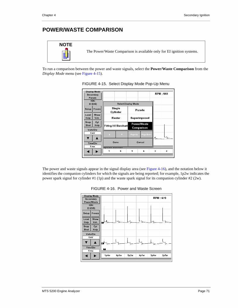
Chapter 4 Secondary Ignition
POWER/WASTE COMPARISON
To run a comparison between the power and waste signals, select the Power/Waste Comparison from the Display Mode menu (see Figure 4-15).
The power and waste signals appear in the signal display area (see Figure 4-16), and the notation below it identifies the companion cylinders for which the signals are being reported; for example, 1p2w indicates the power spark signal for cylinder #1 (1p) and the waste spark signal for its companion cylinder #2 (2w).
NOTEThe Power/Waste Comparison is available only for EI ignition systems.
FIGURE 4-15. Select Display Mode Pop-Up Menu
FIGURE 4-16. Power and Waste Screen
MTS 5200 Engine Analyzer Page 71

Chapter 4 Secondary Ignition
Each power event is listed in firing order sequence and displays its companion cylinder’s waste spark (identified by the ) below the power spark (identified by the ). For best results:
• Run engine at idle while tester initializes with the Secondary Ignition.
• If secondary data displays incorrectly, exit and re-initialize with vehicle off idle (1500 RPM).
SETTINGS
(kV) VOLTS / DIVISION
To adjust the Volts/Div, touch the or buttons to set the proper voltage level. The range of adjustable voltage level is dependent on the Display Mode you have selected. You can immediately see the results of any voltage adjustments.
TIME / DIVISION
The Time/Div control is always available for adjustment and is consistently located in the lower left corner of the touch screen display. This control determines what length of time is being viewed on the display. Time/Div adjustments on the Secondary Ignition display vary with Display Mode selected. Whenever a particular display mode is selected (Parade, Raster, etc.), the previously used Time/Div setting is displayed; however, you can change this adjustment at any time by using the or buttons.
NOTEThe waste signals are only available in the Power/Waste Comparison display mode. The power signals are displayed in all display modes.
W P
MTS 5200 Engine Analyzer Page 72

Chapter 4 Secondary Ignition
SETUP BUTTON
The Setup button (see Figure 4-17) on the Main Menu is part of the default set of controls for the MTS 5200 ignition modes.
Selecting the Setup button gives you access to the Trigger Position, Trigger Cylinder, Ground Offset, and Pattern Spacing buttons (Figure 4-18). These functions are described below.
Main Button
Once you have made your desired Setup changes, touch the Main button to return to the default set of controls on the Display Mode screen.
FIGURE 4-17. Setup Button
Setup Button
FIGURE 4-18. Setup Button Functions
Use the Setupbutton to accessthese functions ⎨
MTS 5200 Engine Analyzer Page 73

Chapter 4 Secondary Ignition
Trigger Position
Trigger Position (see Figure 4-19) enables you to move the secondary ignition pattern to the left and right on the display. The button must be pressed before using the and buttons. The trigger position is indicated by a and correlates to the position of the secondary ignition firing spike. This setting can be changed in 5% increments between 10% (near the left edge of the display) and 90% (near the right edge of the display).
Trigger Cylinder
The Trigger Cylinder control enables you to change the trigger cylinder. The Sync Probe provides a cylinder reference signal when connected to the spark plug wire of the trigger cylinder. The trigger cylinder defaults to cylinder #1 but can be changed to any cylinder in the firing order. For example, cylinder #1 may be difficult to access or may not be operating properly. Regardless of the selected trigger cylinder, the secondary ignition patterns are displayed the same (i.e., the Parade display shows the cylinders in the firing order with cylinder #1 on the left).
Ground Offset
The Ground Offset control allows the ground position and secondary ignition pattern to be moved vertically on the display. The button must be pressed before using the and arrows. The ground position is designated by a on the left side of the signal display area. When you are viewing multiple channels, the Ground Offset does not affect individual cylinders.
NOTES • When testing an EI system, only cylinder #1 and its companion are available as the trigger cylinders.
• The Sync Probe must be connected to the selected trigger cylinder.
T
FIGURE 4-19. Trigger Position
TriggerPositionIndicator
Trigger Position
G
MTS 5200 Engine Analyzer Page 74

Chapter 4 Secondary Ignition
PATTERN SPACING
The MTS 5200 has a feature in the Raster Display mode that allows you to change the spacing between individual cylinder patterns. From the Secondary Raster display screen, touch the Patt Space button. Notice that the Patt Space button becomes the Volts/Div button, and the Volts/Div adjustment box below the Patt Space button becomes the Pattern Space adjustment box. Use the and buttons to increase or decrease the amount of space between the cylinder patterns. When adjusting the pattern space between cylinders, the spacing affects all cylinders whether they are turned off or not. When finished, press the Volts/Div button to toggle the adjustment box back to Volts/Div and the Volts/Div button back to Patt Space.
LEAD HELP BUTTON
Touching the Lead Help button displays a graphic showing the proper connection of the leads to the secondary ignition system.
SHOW VEHICLE BUTTON
The Show Vehicle button displays the selected vehicle information. See “Entering the Test Vehicle” on page 14 to change test vehicle information.
NOTE All adjustments for Volts/Div, Time/Div, Ground Offset, Trigger Position, and Pattern Spacing can be made using either the display buttons or the arrow keys on keypad located below the display.
FIGURE 4-20. Pattern Spacing
Pattern Spacing
MTS 5200 Engine Analyzer Page 75

Chapter 4 Secondary Ignition
ACTIVE BUTTONS SUMMARY
SECONDARY IGNITION ACTIVE BUTTONS
Main Menu(for Single Cylinder, Parade, Raster, and Superimposed Display Modes)
Volts/Div Sets voltage scaling
Time/Div Sets time length being viewed on the display
Setup Accesses Setup functions
Main Returns from Setup menu to Main menu
Trig Pos (Time/Div) Moves trigger position left or right on screen(toggles with Time/Div)
Trig Cyl Selects cylinder to trigger on
Grd Offset (Volts/Div) Moves ground position up or down on screen(toggles with Volts/Div)
Patt Space (Volts/Div) Sets spacing between cylinder patterns (in Raster Display Mode only; replaces Show Veh.) (toggles with Volts/Div)
Freeze Freezes screen display
Run Continues live data display
Save Saves frozen screen to memory
Recall Recalls screen from memory
Lead Help Displays connection of MTS 5200 to vehicle
Show Veh. Displays selected vehicle information (from database)
Snap Shot Accesses the Snapshot functions
Cyl Help Displays cylinder configuration for selected vehicle
Barchart Menus (for Firing kV Barchart Display Modes)Trig Cyl Selects cylinder to trigger on
Freeze Freezes screen display
Save Saves frozen screen to memory
Run Continues live data display
Lead Help Displays connection of MTS 5200 to vehicle
Snap Shot Accesses the Snapshot functions
Reset Resets all values for the barchart data
MTS 5200 Engine Analyzer Page 76
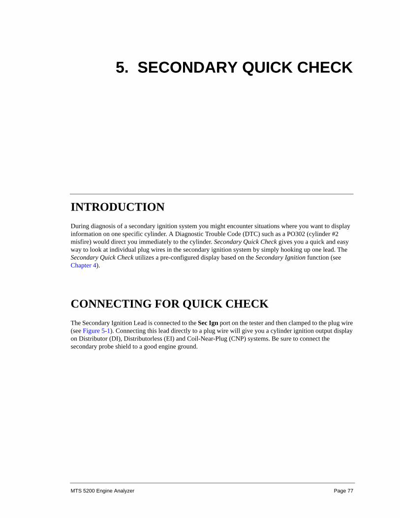
5. SECONDARY QUICK CHECK
INTRODUCTIONDuring diagnosis of a secondary ignition system you might encounter situations where you want to display information on one specific cylinder. A Diagnostic Trouble Code (DTC) such as a PO302 (cylinder #2 misfire) would direct you immediately to the cylinder. Secondary Quick Check gives you a quick and easy way to look at individual plug wires in the secondary ignition system by simply hooking up one lead. The Secondary Quick Check utilizes a pre-configured display based on the Secondary Ignition function (see Chapter 4).
CONNECTING FOR QUICK CHECKThe Secondary Ignition Lead is connected to the Sec Ign port on the tester and then clamped to the plug wire (see Figure 5-1). Connecting this lead directly to a plug wire will give you a cylinder ignition output display on Distributor (DI), Distributorless (EI) and Coil-Near-Plug (CNP) systems. Be sure to connect the secondary probe shield to a good engine ground.
MTS 5200 Engine Analyzer Page 77

Chapter 5 Secondary Quick Check
Enter Secondary Quick Check mode by touching the Secondary Quick Check button on the Main menu. The Secondary Quick Check screen appears (see Figure 5-2).
NOTEAlthough the Secondary Quick Check is fully functional on Distributor Ignition (DI) systems, some applications filter the ignition signal as it passes through the distributor. This distorts the signal at the individual spark plug wires. For this reason, Vetronix recommends using the Secondary Ignition Mode (see Chapter 4) on Distributor Ignition (DI) vehicles.
VEHICLEGROUND
FIGURE 5-1. Quick Check Hookup
FIGURE 5-2. Secondary Quick Check Display
MTS 5200 Engine Analyzer Page 78

Chapter 5 Secondary Quick Check
SETTINGS
SETUP BUTTON
The Setup button on the Secondary Quick Check menu is part of the default set of controls for the MTS 5200 ignition modes. In Secondary Quick Check selecting the Setup button gives you access to the Trigger Position, Lead Help, and Ground Offset buttons.
Main Button
Once you have made your desired Setup changes, touch the Main button to return to the default set of controls on the Secondary Quick Check screen.
Trigger Position Button
Trigger Position enables you to move the secondary ignition pattern to the left and right on the display. The trigger position is indicated by a and correlates to the position of the secondary ignition firing spike. This setting can be changed between 10% (near the left edge of the display) and 90% (near the right edge of the display).
Lead Help Button
Touching the Lead Help button displays a graphic showing the proper connection of the leads to the secondary ignition system.
Ground Offset
The Ground Offset control allows the ground position and secondary ignition pattern to be moved vertically on the display. The ground position is designated by a on the left edge of the display.
FIGURE 5-3. Secondary Quick Check Setup Display
T
G
MTS 5200 Engine Analyzer Page 79

Chapter 5 Secondary Quick Check
(kV) VOLTS / DIVISION
To adjust the Volts/Div, touch the or buttons to set the proper voltage level. The voltage level is adjustable from 1 kV/div to 50 kV/div. You can immediately see the results of any voltage adjustments.
TIME / DIVISION
The Time/Div control is always available for adjustment and is consistently located in the lower left corner of the touch screen display. This control determines what length of time is being viewed on the display. Time/Div adjustments on the Secondary Quick Check display vary from 0.2 ms/div to 2 ms/div. The MTS 5200 will remember the previously used Time/Div setting; however, you can change this adjustment at any time by using the or buttons.
ACTIVE BUTTONS SUMMARY
SECONDARY QUICK CHECK ACTIVE BUTTONS
Main MenuSetup Accesses Setup functions
Main Returns from Setup menu to Main menu
Trig Pos (Time/Div) Moves trigger position left or right on screen(toggles with Time/Div)
Lead Help Displays connection of MTS 5200 to vehicle
Grd Offset (Volts/Div) Moves ground position up or down on screen(toggles with Volts/Div)
Freeze Freezes screen display
Run Continues live data display
Save Saves frozen screen to memory
Recall Recalls screen from memory
Lead Help Displays connection of MTS 5200 to vehicle
Volts/Div Sets voltage level
Time/Div Sets time length being viewed on the display
MTS 5200 Engine Analyzer Page 80

6. VACUUM WAVEFORM
INTRODUCTIONThe Vacuum Waveform diagnostic test mode is a test of the engine’s mechanical health. This test measures the amount of vacuum created by each cylinder of the engine and displays this information as either a high resolution waveform or a percent vacuum per cylinder barchart display. The vacuum information is presented in a crank angle based display with the cylinder numbers displayed at the bottom of the screen in order of the engines intake events (see Figure 6-1).
NOTEHigh vacuum (low pressure) is displayed as a downward slope and Low vacuum (high pressure) is displayed as an upward slope.
FIGURE 6-1. Vacuum Waveform Mode
MTS 5200 Engine Analyzer Page 81

Chapter 6 Vacuum Waveform
CONNECTING THE LEADSTo connect the leads for EI, DI, and CNP Secondary Ignition systems, do the following:
1. Turn the engine off.
2. Connect the Sync Probe to the MTS 5200 and to the trigger cylinder. The default trigger cylinder is cylinder #1.
3. Connect the Vacuum Probe to the MTS 5200 Auxiliary port.
4. Connect the Vacuum Probe’s vacuum hose to a centrally located manifold vacuum source on the vehicle’s intake manifold.
5. Select the test vehicle using vehicle selection, either manually or from the database.
6. Enter the vacuum waveform test mode and calibrate the Vacuum Probe.
7. Make sure that all leads are safely out of the way of moving parts.
8. Start the engine and begin testing.
To connect the leads for COP Ignition systems, do the following:
1. Turn the engine off.
2. Remove the coil pack of the trigger cylinder (leave the coil pack connector connected).
3. Place a jumper spark plug wire from the coil pack to the spark plug that the coil pack was attached to.
4. Connect the Sync Probe to the MTS 5200 and to the jumper spark plug wire that was installed (select this cylinder as the trigger cylinder).
CAUTION
CAUTION!The Vacuum Probe is not designed to measure fluid pressures.
FIGURE 6-2. Typical Lead Connection
MTS 5200 Engine Analyzer Page 82

Chapter 6 Vacuum Waveform
5. Connect the Vacuum Probe to the MTS 5200 Auxiliary port.
6. Connect the Vacuum Probe’s vacuum hose to a centrally located manifold vacuum source on the vehicle’s intake manifold.
7. Select the test vehicle using Manual Vehicle selection.
8. Enter the vacuum waveform test mode and calibrate the Vacuum Probe.
9. Make sure that all leads are safely out of the way of moving parts.
10.Start the engine and begin testing.
TESTING TIPS• The Vacuum Probe comes with a 6-inch length of vacuum hose. Use of a longer hose is not
recommended and will reduce the quality and resolution of the vacuum signal.
• For best results the Vacuum Probe must be attached to a centrally located manifold vacuum source. Connecting to an individual intake runner can cause misleading waveforms. Always try to connect directly to the intake manifold rather than to an external device (e.g., brake booster, fuel pressure regulator, etc.).
• If a problem is detected in the vacuum waveform, always verify the problem by performing a compression and/or cylinder leakage test before repairs are made.
• Turn off accessories such as AC and cooling fans to achieve best results.
• Operate the engine at a steady engine RPM. A surging engine produces a fluctuating waveform that is hard to interpret.
• Correct any backfiring symptoms before attaching the Vacuum Probe to the vehicle.
• Ensure correct settings and basic operation:
• Check static timing.
• Fix any vacuum leaks.
• Fix any obvious ignition or fuel related problem.
• Ensure engine idles as stable as possible.
FIGURE 6-3. Typical COP Lead Connection
MTS 5200 Engine Analyzer Page 83

Chapter 6 Vacuum Waveform
CALIBRATING THE VACUUM PROBEThe Vacuum Probe must be calibrated in order to measure accurate vacuum levels. Calibrating the Vacuum Probe compensates for the altitude at which the test is being performed.
You are asked to calibrate the vacuum transducer when entering a test mode that uses the Vacuum Probe (see Figure 6-4). Once the Vacuum Probe has been calibrated, the tester continues to use that calibration for the duration of the tester’s current power cycle. If the tester’s power is cycled, you are prompted to calibrate again. If you wish to recalibrate the Vacuum Probe without powering down the tester, you can enter the Vacuum Probe Calibration function on the Analyzer Utilities/Tools/Calibration menu.
The following buttons appear on the Vacuum Probe Calibration menu:
• Calibrate: This button starts the Vacuum Probe calibration procedure.
• Use Previous Calibration: This button selects the calibration value from the last time the Vacuum Probe was calibrated.
Observe the following precautions to ensure an accurate calibration:
• Make sure the Vacuum Probe cable is connected to the Auxiliary port of the MTS 5200.
• Make sure the Vacuum Probe cable is connected to the Vacuum Probe.
• Ensure that the Vacuum Probe is not connected to any source of pressure or vacuum. The Vacuum Probe should be exposed to ambient air pressure during the calibration process.
PATTERN DISPLAYThe Display Mode button allows you to select the type of vacuum display which suits your needs best.
To change the display mode, do the following:
1. Touch the Display Mode button at the top left of the touch screen display.
FIGURE 6-4. Vacuum Probe Calibration Menu
MTS 5200 Engine Analyzer Page 84

Chapter 6 Vacuum Waveform
This brings up the Select Display Mode submenu (see Figure 6-5).
2. Use the Select Display Mode button to choose the pattern display you want—Vacuum Waveform or Vacuum Per Cylinder.
3. Touch the Done button to close the menu.
The selected pattern display is indicated on the Display Mode button.
Vacuum Waveform
The Vacuum Waveform display mode allows you to view the vacuum waveform which is produced by the intake stroke of each cylinder. The cylinders are listed in the order of the engine’s intake events. As each cylinder draws air/fuel on its intake stroke, the vacuum waveform displays a downward slope. A normally running engine produces a uniform amount of vacuum on each cylinder.
Engine RPM and the average intake manifold vacuum level are displayed in the upper right portion of the screen. The average manifold vacuum level displays from 30 inHg to 15 psi. (See Figure 6-6.)
FIGURE 6-5. Display Mode and Select Display Mode Pop-up Menu
FIGURE 6-6. Vacuum Waveform Display
MTS 5200 Engine Analyzer Page 85

Chapter 6 Vacuum Waveform
% Vacuum Per Cylinder
The % Vacuum Per Cylinder display mode displays the peak vacuum contribution of each cylinder in a barchart format. Live vacuum values per cylinder are displayed as percentages on the barchart. Each cylinder’s bar represents the amount of vacuum that is being drawn in relationship to the other cylinders. The cylinders are listed in the order of the engine’s intake events.
Numeric values for Live, Minimum, Maximum, and Average vacuum contribution are given below each cylinder’s bar.
The barchart is scaled from 0 to 100%. 0% is located at the top of the bar and 100% at the bottom. A low percentage reading indicates a cylinder which has poor contribution to the overall intake manifold vacuum level.
Engine RPM and the average intake manifold vacuum level are displayed in the lower right portion of the screen. The average manifold vacuum level displays from 30 inHg to 15 psi. See Figure 6-7.
SETTINGS
Units/Div
To adjust the Units/Div, touch the up or down buttons to set the proper level. The range of adjustable voltage level is dependent on the units of measure you have selected. You can immediately see the results of any units of measure adjustments.
Units of either inHg or mbar can be selected for use in vacuum displays. The units that you wish to use can be selected in the Units of Measure screen located under Analyzer Utilities/Tools/Units of Measure (see “Measurements and Settings” on page 174).
FIGURE 6-7. Vacuum Per Cylinder Display
MTS 5200 Engine Analyzer Page 86

Chapter 6 Vacuum Waveform
Smoothing
To adjust the Smoothing, touch the right or left arrow buttons to set the smoothing to the desired level. Four settings are available—Off, Low, Medium, and High. You can immediately see the results of any smoothing adjustments (see Figure 6-8).
The smoothing function allows you to adjust the level of high frequency filter that is applied to the vacuum waveform. The Off setting displays the raw, unfiltered vacuum signal from the Vacuum Probe.
Smoothing is typically used on vehicles that produce a vacuum waveform which inherently has a lot of high frequency vacuum activity. Smoothing enables a more accurate analysis of vacuum waveforms on vehicles equipped with multiple intake valves per cylinder or a large number of cylinders.
NOTESmoothing adjustments may affect the amplitude of the vacuum waveform.
FIGURE 6-8. Smoothing Adjustment (Medium)
SmoothingAdjustment
MTS 5200 Engine Analyzer Page 87
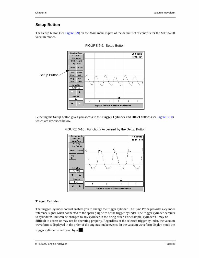
Chapter 6 Vacuum Waveform
Setup Button
The Setup button (see Figure 6-9) on the Main menu is part of the default set of controls for the MTS 5200 vacuum modes.
Selecting the Setup button gives you access to the Trigger Cylinder and Offset buttons (see Figure 6-10), which are described below.
Trigger Cylinder
The Trigger Cylinder control enables you to change the trigger cylinder. The Sync Probe provides a cylinder reference signal when connected to the spark plug wire of the trigger cylinder. The trigger cylinder defaults to cylinder #1 but can be changed to any cylinder in the firing order. For example, cylinder #1 may be difficult to access or may not be operating properly. Regardless of the selected trigger cylinder, the vacuum waveform is displayed in the order of the engines intake events. In the vacuum waveform display mode the
trigger cylinder is indicated by a .
FIGURE 6-9. Setup Button
Setup Button
FIGURE 6-10. Functions Accessed by the Setup Button
T
MTS 5200 Engine Analyzer Page 88

Chapter 6 Vacuum Waveform
Ground Offset
The Ground Offset control (see Figure 6-11) allows the vacuum waveform to be moved vertically on the display. The Ground Offset button must be pressed before using the up and down arrows.
Main Button
Once you have made your desired setup changes, touch the Main button to return to the default set of controls on the Display Mode screen.
Lead Help
Touching the Lead Help button displays a graphic showing the proper connection of the leads to the vehicle.
Show Vehicle Button
The Show Vehicle button displays the selected vehicle information. See “Entering the Test Vehicle” on page 14 to change test vehicle information.
NOTE • When testing an EI system, only cylinder #1 and its companion are available as the trigger cylinders.
• The Sync Probe must be connected to the selected trigger cylinder.
FIGURE 6-11. Ground Offset and Trigger Cylinder Indicator
GroundOffsetAdjustment
TriggerCylinderIndicator
MTS 5200 Engine Analyzer Page 89

Chapter 6 Vacuum Waveform
ACTIVE BUTTONS SUMMARY
VACUUM WAVEFORM ACTIVE BUTTONS
Button DescriptionUnits/Div Sets either inHg or mbar scaling
Smoothing Sets the filter level for the vacuum waveform
Setup Accesses Setup functions
Main Returns from Setup menu to Main menu
Trig Cyl Selects cylinder to trigger on
Offset (Units/Div) Moves ground position up or down on screen (toggles with Units/Div)
Freeze Freezes screen display
Run Continues live data display
Save Saves frozen screen or snapshot to memory
Recall Recalls screen from memory
Lead Help Displays connection of MTS 5200 to vehicle
Show Veh. Displays selected vehicle information
Snap Shot Accesses the Snapshot functions
Cyl Help Displays cylinder configuration for selected vehicle (from database)
VACUUM PER CYLINDER ACTIVE BUTTONS
Button DescriptionTrig Cyl Selects cylinder to trigger on
Freeze Freezes screen display
Save Saves frozen screen to memory
Run Continues live data display
Lead Help Displays connection of MTS 5200 to vehicle
Snap Shot Accesses the Snapshot functions
Reset Resets all values for the barchart data
MTS 5200 Engine Analyzer Page 90

7. CRANKING kV TEST
INTRODUCTIONThe Cranking kV Test allows you to perform a quick diagnosis of the secondary ignition system’s ability to produce spark at cranking engine speed. This test gives you a simple pass/fail result along with detailed information about the health of the secondary ignition system.
CONNECTING THE LEADS
DISTRIBUTOR IGNITION SYSTEM (DI)
SECONDARY IGNITION DI (DIST. IGN.)
TRIGGERCYLINDER
VEHICLEGROUND
FIGURE 7-1. DI Cranking kV Test Hookup
MTS 5200 Engine Analyzer Page 91

Chapter 7 Cranking kV Test
The Distributor Ignition system is the most common ignition system for early model year vehicles. While the DI system has many mechanical parts, it is the easiest to connect to. It has one coil that fires one spark plug at a time on the compression stroke only. Refer to Figure 7-1 for an example of a standard cranking kV test hookup.
Connecting the Leads
To connect the leads for a standard DI Secondary Ignition, do the following:
1. Connect the Sync Probe to the MTS 5200 and to the trigger cylinder ignition lead. The default trigger cylinder is cylinder #1.
2. Connect the single secondary ignition lead to the MTS 5200.
3. Connect the probe end of the single secondary ignition lead to the coil wire.
4. Connect the ground shield end of the single secondary ignition lead to a good vehicle ground.
5. Make sure that all leads are safely out of the way of moving parts.
ELECTRONIC IGNITION SYSTEM (DIS)
For a discussion of EI (DIS) systems, see “Electronic Ignition System (DIS)” on page 58.
Spider Leads and Junction Box
EI (DIS) systems require each cylinder’s ignition wire to be connected to one of the secondary ignition probes. Refer to Figure 7-2 for required hardware.
NOTE If the Sync probe is placed on the ignition lead in the wrong orientation, the kV levels for all cylinders except the first in the firing order will appear very low. The Check Sync Probe message is not displayed.
TESTER
EI (DIS) JUNCTION BOX
VEHICLEGROUND
FIGURE 7-2. EI (DIS) Cranking kV Test Setup
MTS 5200 Engine Analyzer Page 92

Chapter 7 Cranking kV Test
The EI (DIS) Lead Hook-up screen (see Figure 7-3) is shown when an EI (DIS) vehicle is selected and displays the following information:
• Firing Order as selected from the Manual Vehicle Set-up or from the vehicle database.
• Connections for the red and black EI (DIS) lead set to the correct spark plug wires. This is done to separate the simultaneous power and waste spark events.
• Cyl Help button to display the cylinder configuration for the selected vehicle from the vehicle database. This button is inactive (grayed out) if the vehicle selection was made through the Manual Vehicle Set-up menu
• Connections for the EI (DIS) junction box and Sync Probe to the Engine Analyzer and vehicle.
• Connection for the Sync Probe to the trigger cylinder.
Pressing either the Enter button from the keypad or the Continue button on the screen closes the Lead Hook-Up menu and starts the secondary signal display.
Connecting the Leads
The MTS 5200 can display all cylinders at one time for vehicles with electronic ignition systems.
Use the following steps to connect the leads:
1. Connect Sync Probe to the trigger cylinder ignition lead (default is cylinder #1).
2. Connect the junction box to the SEC IGN port or connector on the MTS 5200.
3. Connect the necessary EI lead set to the junction box.
NOTE The Sync Probe will only trigger on cylinder #1 or its companion cylinder. If the companion cylinder is used, the Trigger Cylinder can be changed in the software by selecting the Trig Cyl button located on the menu screen.
FIGURE 7-3. EI (DIS) Lead Hook-Up Screen
MTS 5200 Engine Analyzer Page 93

Chapter 7 Cranking kV Test
4. Connect red EI leads to the spark plug wires of the first half of the firing order.
5. Connect black EI leads to the spark plug wires of the second half of the firing order.
6. Connect black ground clamp to the vehicle ground.
COIL NEAR PLUG (CNP) IGNITION SYSTEMS
Coil Near Plug ignition systems use one coil for each cylinder. The coils are usually mounted in close proximity, usually on the valve cover, to the spark plug that it fires. A short spark plug wire connects the coil to its spark plug.
Connecting the Leads
Use the following guidelines to connect the leads for CNP systems:
• Connect the EI lead set to the individual spark plug wires.
• Disregard red and black color coding.
• Only connect the necessary amount of EI leads to the junction box.
• Connect the Sync Probe to the trigger cylinder ignition lead (default trigger cylinder is #1).
BEGINNING THE TESTTo select the Cranking kV Test, do the following:
1. Press the Engine Tests button on the Main menu.
2. Press the Cranking kV Test button on the Engine Tests menu.
3. Select the vehicle under test from the vehicle selection process. See “Entering the Test Vehicle” on page 14 for instructions about selecting the test vehicle.
Once you select the test vehicle, a message appears describing the basic setup requirements and safety precautions to follow during the test procedure.
MTS 5200 Engine Analyzer Page 94

Chapter 7 Cranking kV Test
4. Press the Continue button.
TEST SCREENAfter you press the Continue button, you see the Cranking kV Test screen, a standard barchart display showing live kV levels as shaded bars for each cylinder. The cylinder number is displayed below the data for each cylinder in firing order.
The bars grow from bottom to top. As a measured value increases, auto scaling automatically changes the vertical scale to prevent the displayed value from moving off the grid.
The Test screen contains the following display features:
FIGURE 7-4. Cranking kV Test Setup Message
FIGURE 7-5. Test Screen for Cranking kV Test
MTS 5200 Engine Analyzer Page 95

Chapter 7 Cranking kV Test
LIVE/MIN/MAX/AVG DATA
kV values are represented by the shaded area of each cylinder bar as well as numerically below each cylinder bar in the Live data row.
Maximum and minimum kV values are represented by horizontal marks across each cylinder bar as well as numerically below each cylinder bar in the Min and Max data rows.
Average data for each cylinder bar is displayed numerically below each cylinder bar in the Avg data row.
ENGINE INFORMATION
The ignition type and trigger cylinder selection are displayed in the lower left corner of the Test screen.
ENGINE DATA
In the lower right corner of the Test screen, live RPM reading is displayed whenever RPM is detected. Otherwise, No Signal is displayed.
The Test Timer is displayed below the RPM. This timer counts down the Test Duration when the Cranking kV Test is being performed to let you know how long to crank the engine. It becomes active when the Start Test button is pressed and RPM is detected. You can adjust the duration of the test by entering the Cranking Test Setup screen in the Analyzer Utilities (see “Setup” on page 101).
The Check Sync Probe message appears (if applicable) below the other engine data. If it appears during the Test Duration, it means you have lost your sync signal, and the Test Duration is not complete.
ACTIVE BUTTONS
Start Test
When the Start Test button is pressed, you are prompted to start cranking the engine, and the tester begins collecting data. This button is linked to the Enter keypad button.
Lead Help
Pressing Lead Help displays a graphic of the appropriate lead setup for the selected vehicle.
Trig Cyl
Pressing Trig Cyl displays the Select Trigger Cylinder list box where you can select the appropriate trigger cylinder.
Cyl Help
Pressing Cyl Help displays the appropriate cylinder layout graphic for the selected vehicle.
MTS 5200 Engine Analyzer Page 96

Chapter 7 Cranking kV Test
EXIT Keypad Button
Pressing EXIT cancels the Cranking kV Test mode and returns you to the Engine Tests menu.
Help Keypad Button
Pressing HELP takes you to the appropriate section of the help file.
RUNNING THE TESTWhen the Start Test button is pressed, a Begin Cranking Engine to Start Test message appears:
When the message appears, the test begins monitoring inputs to detect a cranking engine.
FIGURE 7-6. Begin Cranking Message
FIGURE 7-7. Acquiring Ignition Signals Message to Start Test
MTS 5200 Engine Analyzer Page 97

Chapter 7 Cranking kV Test
When the ignition signals are detected, data begins to be collected. The Test Timer begins counting down as soon as engine cranking is detected.
The following data parameters are collected during the test:
Live Firing kV: Each update of firing kV for each cylinder for the duration of the test.
Live Engine RPM: Each update of engine RPM during the duration of the test.
Test Duration: The Test Timer counts down the amount of time you set in the Cranking Test Setup (see “kV Test Duration” on page 101). If at any time during the test the Sync Probe signal is lost, the Check Sync Probe message displays, and the Test Duration is not met. If the Sync Probe signal is lost during the test, the message Duration not met, crank engine for entire test is displayed in the results screen.
As soon as the Test Time reaches zero, the Stop Cranking Engine message appears.
DISPLAYING RESULTSTest results are displayed in the barchart format on the Results screen. The top of the results screen looks very much like the Test screen, including the Min/Max/Avg kV results for each cylinder.
FIGURE 7-8. Stop Cranking Engine Message
MTS 5200 Engine Analyzer Page 98

Chapter 7 Cranking kV Test
MIN/MAX/AVG DATA
The bars represent the average kV detected for each cylinder during the test. Minimum/maximum/average kV values collected during the test are listed numerically below each cylinder bar.
Maximum and minimum kV values are represented by tic marks on each cylinder bar.
PASS/FAIL INDICATOR
In the center of the lower portion of the Results screen appears a message indicating if the test passed or failed. If it fails, the reason for the failure is displayed below the Test Fail message. Possible reasons for test failure include insufficient kV levels to reach the set threshold or loss of RPM or failure to reach test duration.
FIGURE 7-9. Cranking kV Test Results Screen
FIGURE 7-10. Cranking kV Test Failure Screen
MTS 5200 Engine Analyzer Page 99

Chapter 7 Cranking kV Test
AVERAGE RPM
The average RPM reading for the test is displayed in the lower right.
AVERAGE kV
The average kV reading for the test is displayed in the lower right. This average is the sum of each of the cylinder’s individual average values divided by the number of cylinders.
CRANKING kV THRESHOLD
The cranking kV threshold you selected in Cranking Test Setup is displayed in the lower left.
ACTION BUTTONS
The following buttons enable you to determine what is to be done with the results obtained from the test.
Re-Test Button
Returns you to the Test screen to start the Cranking kV test again.
Save Button
Saves the current Results screen to memory as a bitmap image. You are prompted to enter notes using the Edit Notes keyboard.
EXIT Keypad Button
Returns you to the Engine Test menu. If the current results have not been saved, you are prompted with a message asking if you want to save the test results, and you can choose to either save the results or exit the test.
HELP Keypad Button
Takes you to the appropriate section of the help file.
SAVING RESULTSWhen the Save button on the Results screen is pressed, your results are saved to memory as bitmaps. These files are located with all other saved bitmap files and are available for viewing, uploading, editing, and deleting in the File Manager.
Saved Cranking kV test results screens have file names beginning with CKK followed by an automatically assigned number (i.e., CKKnn.bmp).
MTS 5200 Engine Analyzer Page 100

Chapter 7 Cranking kV Test
If the results of the test are not saved and you press the EXIT keypad button, the message Would you like to save the test results? appears. Pressing Yes causes the Edit Notes screen to appear; pressing No returns you to the Engine Test menu.
SETUPThe Cranking Test Setup screen enables you to set the Cranking kV Threshold and the Test Duration. From the MTS 5200 Main menu, select the following path to open the setup screen:
Analyzer Utilities → Setup → Measurements and Settings → Cranking Test Setup
The Cranking Test Setup screen allows you to select several options.
Kv THRESHOLD
Select the kV threshold from 2 to 12 kV in 1 kV increments using the up and down arrows (or the up and down arrow keyboard buttons). The default value is 7 kV.
Kv TEST DURATION
Select the test duration from 5 to 15 seconds in 1 second increments using the left and right arrows (or the left and right arrow keypad buttons). The default value is 10 seconds.
DEFAULT SETTINGS
Select this button to reset the threshold and test duration to the factory-set defaults: 7 kV and 10 seconds.
FIGURE 7-11. Cranking Test Setup Screen
MTS 5200 Engine Analyzer Page 101

Chapter 7 Cranking kV Test
CONTINUE
Press the Continue button to save the current settings and return to the MTS 5200 Measurements and Settings menu.
CANCEL
Press the Cancel button to revert to the settings that were last saved and return to the MTS 5200 Measurements and Settings menu.
ACTIVE BUTTONS SUMMARY
CRANKING kV TEST ACTIVE BUTTONS
Button Description (Location Screen)Start Test Begins the Cranking kV Test (Test screen).
Lead Help Displays graphic help for connecting leads for selected vehicle (Test screen).
Trig Cyl Displays Select Trigger Cylinder list box to select the appropriate trigger cylinder (Test screen).
Cyl Help Displays graphic of the cylinder layout for selected vehicle (Test screen). If the vehicle selection was made through the Manual Vehicle Set-up menu, the Cyl Help button is inactive (grayed out).
Re-Test Displays the Test screen to begin the test again (Results screen).
Save Saves the current screen to memory (Results screen).
Default Settings Resets the kV Threshold and Test Duration values to the defaults (Cranking Test Setup screen).
MTS 5200 Engine Analyzer Page 102

8. CYLINDER TESTS
The following cylinder tests are discussed in this chapter:
Cylinder Balance . . . . . . . . . . . . . . . . . . . . . . . . . . . . . . . . . . . . . page 104
The Cylinder Balance test for vehicles with DI systems deactivates cylinders using either a manual or automated test to measure their performance. At the end of the test you can review the results in a barchart format for each cylinder to determine which are not performing equally to the rest of the cylinders.
Failed Cylinder ID . . . . . . . . . . . . . . . . . . . . . . . . . . . . . . . . . . . page 121
The Failed Cylinder ID (FCI) test for OBD II compliant vehicles identifies problems that indicate one or more malfunctioning cylinders by monitoring the OBD II system while running the vehicle through a timed test. At the end of the test you can see the results and a test log of all information that was collected from the vehicle’s OBD II system during testing.
MTS 5200 Engine Analyzer Page 103

Chapter 8
CYLINDER BALANCE
CYLINDER BALANCE INTRODUCTIONThe Cylinder Balance mode enables you to test and rate each cylinder on vehicles with DI systems. This test mode intrusively deactivates cylinders using either a manual or automated test. When the test completes, you can review the results in a barchart format to determine which cylinders are not performing equally to the rest of the cylinders.
OVERVIEW
If each cylinder contributes to the overall engine RPM, then the elimination of one (or more) cylinder’s ignition firing reduces the engine RPM proportional to the eliminated cylinder’s contribution. Thus, a cylinder’s performance can be measured by comparing the engine’s rotational speed with all cylinders “enabled” (ENA) and with one (or more) cylinder “disabled” (DIS).
As an optional feature you can test the DC vacuum difference between the enabled and disabled states. The DC vacuum is measured at a central port in the intake manifold, and the data is captured at the same time the RPM difference data is captured.
The MTS 5200 Engine Analyzer provides two methods of disabling an internal combustion engine’s primary ignition for evaluating each cylinder’s contribution to the overall engine RPM:
• Manual mode, where you select the cylinder(s) to disable.
• Automated mode, where the Analyzer disables cylinders sequentially through the firing order.
NOTE The cylinder balance test only supports DI systems where a single coil provides ignition to all spark plugs for the engine. It supports external coil systems and some internal coil systems that permit intrusive monitoring of the primary ignition circuit. Monitoring requires access to the coil primary circuit negative terminal.
NOTESome vehicles are equipped with an auxiliary “tach” output signal (usually located at the distributor or at the ignition module) which appears to be the same signal that is seen at the coil negative terminal. However, in some cases this circuit has protection that will not allow the MTS 5200 to disable the ignition firing. In this case you should ensure that the primary ignition lead is connected directly to the ignition coil’s negative post.
MTS 5200 Engine Analyzer Page 104

Chapter 8
MANUAL VS. AUTOMATED TEST
MANUAL TEST
The technician selects one or more cylinders to be disabled. Pressing the Disable button disables all selected cylinders in a given ignition cycle (720°). The Ignition Disable Duration setting in the Setup menu defines the length of time the test runs after the Disable button is pressed. Default values are shown in Table 8-1. The shaded area of the bar graph displays the average RPM difference between the DIS and ENA values for a set number of data points. The barchart also displays a horizontal marker tracking the maximum RPM difference.
AUTOMATED TEST
Pressing the Disable key begins the test by disabling the first cylinder in the firing order. The disabling runs for a predetermined time, followed by a recovery period during which the engine RPM is allowed to stabilize before the next cylinder in the firing order is disabled. (Default values are shown in Table 8-1.) The test continues until all cylinders in the firing order have been sequentially disabled. A maximum average RPM difference for a set number of data points is displayed for the active (disabled) cylinder, and following the disabling period, the last data update is frozen in the barchart display.
TABLE 8-1. Constant Values for Cylinder Balance Tests*
*. When new software is installed, default settings are restored.
FIELD VALUE MODE
Minimum Ignition Disable Duration Time
5 seconds Manual Mode
Maximum Ignition Disable Duration Time
20 seconds Manual Mode
Resolution of Ignition Disable Duration
1 second Manual Mode
Default Disable Duration 10 seconds Manual Mode
Default Sync Cylinder Cylinder #1 Manual and Automated Modes
Y-Axis Scale ±25 RPM Manual and Automated Modes
Update Rate for all barchart data parameters and graphing
2 Hz (minimum) Manual and Automated Modes
MTS 5200 Engine Analyzer Page 105

Chapter 8
CONNECTING THE LEADSPrior to running the test, you must attach the Sync Probe and the primary ignition lead set. The Vacuum Probe, which is optional, may also be attached for DC measurement.
To set up the cylinder balance test, do the following:
1. Connect the primary ignition lead set:
a. Attach the large black lead to the vehicles battery ground.
b. Attach the large red lead to the vehicle’s battery positive 12 Volt DC source.
c. Attach the small red lead to the vehicle’s ignition coil primary circuit negative terminal.
d. Attach the primary ignition lead to the MTS 5200 PRI IGN port.
2. Connect the Sync Probe to the secondary ignition lead of the trigger cylinder (selected by the technician) and to the MTS 5200 SYNC port.
3. (Optional) Connect the Vacuum Probe to a central vacuum port on the vehicle's intake manifold. Attach the connector to the MTS 5200 AUXILLARY port
WARNING! Before starting the test, be certain you check the following:
• Set the parking brake.
• Block the drive wheels.
• Place the transmission in Park or Neutral.
• Run the engine at constant off idle speed.
FIGURE 8-1. Cylinder Balance Test Connections
MTS 5200 Engine Analyzer Page 106

Chapter 8
SETTING UP THE TEST
SELECTING THE VEHICLE
To select the vehicle, do the following:
1. Press the ON/OFF button to turn on the MTS 5200.
The Main menu appears.
2. Select Engine Tests on the Main menu of the MTS 5200.
The Engine Test menu appears.
3. Select Cylinder Tests on the Engine Tests menu.
The Cylinder Tests menu appears.
FIGURE 8-2. MTS 5200 Main Menu
FIGURE 8-3. Engine Tests Menu
MTS 5200 Engine Analyzer Page 107
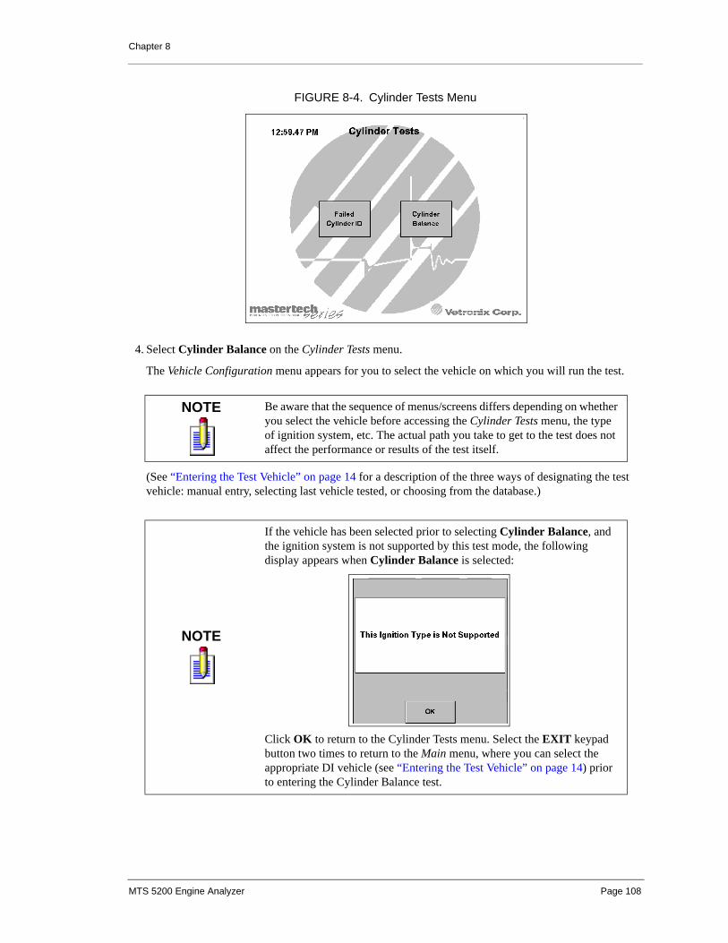
Chapter 8
4. Select Cylinder Balance on the Cylinder Tests menu.
The Vehicle Configuration menu appears for you to select the vehicle on which you will run the test.
(See “Entering the Test Vehicle” on page 14 for a description of the three ways of designating the test vehicle: manual entry, selecting last vehicle tested, or choosing from the database.)
NOTE Be aware that the sequence of menus/screens differs depending on whether you select the vehicle before accessing the Cylinder Tests menu, the type of ignition system, etc. The actual path you take to get to the test does not affect the performance or results of the test itself.
NOTE
If the vehicle has been selected prior to selecting Cylinder Balance, and the ignition system is not supported by this test mode, the following display appears when Cylinder Balance is selected:
Click OK to return to the Cylinder Tests menu. Select the EXIT keypad button two times to return to the Main menu, where you can select the appropriate DI vehicle (see “Entering the Test Vehicle” on page 14) prior to entering the Cylinder Balance test.
FIGURE 8-4. Cylinder Tests Menu
MTS 5200 Engine Analyzer Page 108

Chapter 8
5. Once you have selected the vehicle, click OK to confirm the your choice, and the Vacuum Probe Calibration menu appears. (Click Cancel to return to the Cylinder Tests menu. Select the EXIT keypad button two times to return to the Main menu, where you can select the appropriate DI vehicle prior to entering the Cylinder Balance test. See “Entering the Test Vehicle” on page 14 for more information.)
CALIBRATING THE VACUUM PROBE
The Vacuum Probe Calibration menu presents three options when a previous vacuum calibration value exists in the tester’s start up file:
NOTE
If a DI system vehicle with an internal coil has been selected, then the following message is displayed:
Click OK to continue, and the calibration dialog appears. Select Cancel to return to the Cylinder Tests menu. Select the EXIT keypad button two times to return to the Main menu, where you can select the appropriate DI vehicle (see “Entering the Test Vehicle” on page 14) prior to entering the Cylinder Balance test.
NOTE If the Vacuum Probe has not been calibrated since new software was installed, then the Use Previous Calibration selection does not appear on the menu.
FIGURE 8-5. Vacuum Probe Calibration Menu
MTS 5200 Engine Analyzer Page 109

Chapter 8
To calibrate the Vacuum Probe, do the following:
1. Choose one of the following options on the Vacuum Probe Calibration menu:
a. Select Calibrate to overwrite any previous value with a new calibration value or to calibrate the probe if no previous value exists. Click OK. (Go to Step 2.)
or
b. Select Use Previous Calibration to leave the previous calibration value as the set value and click OK. (Go to Step 3.) This option does not appear if no previous calibration value exists.
or
c. Select No Vacuum Probe Used if you do not want vacuum data to display in the cylinder balance screens and click OK. (Go to Step 3.)
2. When the Calibration Message screen appears, follow the instructions and click OK.
3. When the calibration procedure completes, the pop-up SETUP message appears on top of the Cylinder Balance main screen.
Ensure that all the setup tasks have been performed, and press the Continue button to enter the Cylinder Balance screen.
FIGURE 8-6. Calibration Message
FIGURE 8-7. Cylinder Balance Setup Screen
MTS 5200 Engine Analyzer Page 110

Chapter 8
SELECTING THE TEST MODE
To select the cylinder balance test mode, do the following:
1. Manual Balance: This is the default that first appears. Go to “Running the Manual Test” on page 112 to continue.
2. Automated Balance:
a. Select the Test Mode button (which by default shows Manual Balance).
b. The Select Test Mode dialog pops up.
c. Select Automated Balance.
d. Press Done. Go to “Running the Automated Test” on page 117 to continue.
SETTING IGNITION DISABLE DURATION
In manual test mode you are able to adjust the time during which ignition is disabled by accessing the Ignition Disable Duration dialog in Analyzer Utilities > Setup > Measurements and Settings.
FIGURE 8-8. Select Test Mode Dialog
FIGURE 8-9. Ignition Disable Duration Dialog
MTS 5200 Engine Analyzer Page 111

Chapter 8
The default duration is 10.0 seconds for manual balance. You can adjust the slider using the left and right arrow buttons (or left and right arrow keypad buttons) to set the disable duration to a value from 5.0 seconds to 20.0 seconds in 1.0 second intervals.
Use the Default Setting button to return to the 10.0 seconds duration. Press Continue (or press Enter on the MTS 5200 keypad) to overwrite the previous Ignition Disable Duration setting with the new value. Press the Cancel button (or Exit on the keypad) to return to the Measurements and Settings menu and revert to the previously saved value.
RUNNING THE MANUAL TEST
MANUAL BALANCE TEST INITIAL SCREEN
The Cylinder Balance test initially defaults to the Manual Balance test mode, and the initial screen is displayed in Figure 8-10.
Each cylinder’s Δ-RPM is graphically represented by vertical bars each with a horizontal line dividing it and representing 0 RPM. On the first cylinder is the average RPM difference scale, which automatically scales in the upward direction as necessary (see A in Figure 8-10). The cylinders are arranged in firing order and identified by a box/button below each bar graph (see B in Figure 8-10).
Below each cylinder bar are three or four data lines, depending on whether you are using the vacuum probe. The test data reported are as follows (see C in Figure 8-10):
All values remain dashed out until a cylinder is selected for disabling and the Disable button is pressed, at which time the average ENA RPM values are posted for the selected cylinders once a set number of readings are reported.
When present, the live engine RPM and live DC vacuum appear in the lower right (D in Figure 8-10).
The Check Sync Probe message (E in Figure 8-10) appears when no Sync signal is present.
ENA Enabled RPM–Latest average engine RPM of a set number of data points without ignition interruption.
DIS Disabled RPM–Latest average engine RPM of a set number of data points with ignition interrupted (disabled).
Δ-RPM Delta RPM–Difference between DIS and ENA.
Δ-VAC Delta VAC–Difference between disabled and enabled average of a set number of data points of vacuum DC measurements. NOTE: If vacuum is not selected in the Vacuum Probe Calibration menu, Δ-VAC values do not appear.
MTS 5200 Engine Analyzer Page 112

Chapter 8
The following buttons appear on the screen:
MANUAL BALANCE ENABLE/DISABLE STATE
Before starting the test, the Disable button is inactive (grayed out). When you select one or more cylinders for disabling, and live engine RPM and live DC vacuum readings (if selected in the Calibration menu) are available, the Disable button becomes active (black). Press the Disable button, and the MTS 5200 displays the ENA value and begins collecting the disable RPM (DIS) data and calculating the Δ-RPM value.
Test Mode Manual Balance is the default test mode. Press the Manual Balance button to bring up the Select Test Mode dialog to select Automated Balance. The text on the test mode button indicates the active test mode.
Trigger Cylinder Press the Trig Cyl button to select the trigger cylinder for the test. The Select Trigger Cylinder dialog appears, on which you can make your selection. The selected trigger cylinder is indicated in the lower left corner of the screen (F on Figure 8-10).
Lead Help Press the Lead Help button to view a diagram of the lead connections for the cylinder balance test.
Disable (inactive) Initially the Disable button is inactive (grayed out). The button becomes active when one or more cylinders are selected for disabling and when a set number of RPM readings have been made. Pressing the Disable button when it is active interrupts the ignition firing on the selected cylinder(s), and the text of the button changes to Enable.
Freeze The Freeze button stops refreshing the screen live values and displays the Freeze menu, which enables the Save, Run, and Recall buttons. See “Freeze Button” on page 119 for more details.
Reset The Reset button momentarily clears all the current live values, deselects all cylinders, sets the bar chart RPM difference scale back to the lowest setting, sets the maximum difference marker to zero, removes the digital data values, and toggles the Disable button to the inactive state.
FIGURE 8-10. Initial Manual Balance Test Screen
A
B
C
D
E
F
MTS 5200 Engine Analyzer Page 113

Chapter 8
To begin the manual test, do the following:
1. Select one or more cylinders to be disabled, using the buttons below the barcharts. (The cylinder number button changes to a darker shade when selected.)
The MTS 5200 Engine Analyzer begins collecting live RPM and vacuum data, which is displayed and updated in the live data fields as long as the Sync signal is available. (If the Sync signal is lost, the Check Sync Probe and No Signal messages are displayed.)
When the ENA buffer captures a set number of data points, the Disable button becomes active (gray to black), and the MTS 5200 Engine Analyzer is ready to begin the test.
In Figure 8-11 cylinders 6, 4, and 2 have been selected to be tested, the ENA buffer has the necessary data (as indicated by the active Disable button), and the MTS 5200 is ready to run the test.
2. Select the Disable button to disable the designated cylinders and start the test. Notice that in the disable state the button changes to read Enable.
NOTE The buttons below cylinders which are not selected for testing remain white. If the unselected cylinder has been tested previously, the earlier captured digital and graphical data remains displayed.
FIGURE 8-11. Manual Balance Enable State Screen
MTS 5200 Engine Analyzer Page 114

Chapter 8
Only the cylinders selected for disabling have data updated in the disable state. All other cylinders have information frozen as it was for comparison with the test data.
The DIS data displays and updates as long as the primary signal is present. At the end of the disabling period, the DIS values remain frozen in the digital and bar graph displays. The ENA value for the selected cylinders is frozen at the most recent value prior to selection of the Disable button.
If the primary signal is lost during a disable state, the message in Figure 8-13 appears.
3. Select the Enable button to stop the test, or wait until the Cylinder Balance test exits (depending on the time duration you entered on the Settings menu).
COMPLETING THE MANUAL TEST
Upon completion of the manual test, the Enable key toggles to Disable (inactive state), and the selected cylinders are deselected, allowing you to select additional cylinders for disabling. Since previously captured
FIGURE 8-12. Manual Balance Disable State Screen
FIGURE 8-13. Signal Not Detected Message
MTS 5200 Engine Analyzer Page 115

Chapter 8
data on cylinders not selected for disabling is not cleared, new balance tests can be run on these cylinders. However, selection of previously disabled cylinders overwrites the previous data.
If the engine is running and the signal is available, live engine RPM continues to update. Otherwise, the No Signal and Check Sync Probe messages display.
If the engine is running and the Vacuum Probe is connected (and was selected in the Vacuum Probe Calibration menu), live vacuum data continues to update. If the Vacuum Probe is not connected and the Analyzer continues to get a Sync signal, live vacuum data displays the open circuit voltage equivalent DC vacuum value.
To exit the manual test mode, press the EXIT keypad button.
Manual Test Active Menu Keys Summary
NOTETo save the results of the current manual balance test, use the Freeze button to access the Save function.
ENABLE STATE ACTIVE MENU KEYS
Test Mode Indicates Manual Balance test mode.
Trig Cyl Permits selection of cylinder to trigger.
Lead Help Brings up an illustration showing how to connect the MTS 5200 to the vehicle to run the Cylinder Balance test.
Disable If the set number of RPM data points has been captured, and at least one cylinder has been selected, the Disable button is active.
Cylinder Selection Buttons
Allows selection of cylinders to be disabled during the Cylinder Balance test. The background of the buttons turns a darker shade when the button is selected.
FreezeStops refreshing screen values. ENA values no longer update. Enable button disappears from the display. The Frozen message flashes at one-second intervals. The Test Mode button toggles to the inactive state (gray lettering). See “Freeze Button” on page 119.
ResetReturns the test screen to its initial state with digital values set to dashes, bar graphs’ shading removed, maximum difference marker set to zero, cylinder buttons unselected, buttons unselected, Disable button set to inactive, and live values momentarily reset to dashes.
DISABLE STATE ACTIVE MENU KEYS
Enable Allows all cylinder ignition firing and freezes the barchart display with the last values captured during the disable period.
MTS 5200 Engine Analyzer Page 116

Chapter 8
RUNNING THE AUTOMATED TEST
AUTOMATED BALANCE ENABLE/DISABLE STATE
The moment you select Automated Balance test mode and click Done on the Select Test Mode screen, the MTS 5200 begins collecting the engine RPM data.
The cylinder keys and Reset button are not selectable in Automated Balance mode.
Select the Disable key to begin the Automated Balance test. (In the disable state the Disable button changes to read Cancel and remains Cancel until the Automated Balance test completes.) .
Disabling begins with the first cylinder in the firing order. Once this cylinder has been disabled for the set duration, a recovery period follows during which no cylinder’s ignition firing is interrupted. The recovery
FIGURE 8-14. Automated Balance Enable State Screen
FIGURE 8-15. Automated Balance Disable State Screen
MTS 5200 Engine Analyzer Page 117

Chapter 8
period allows the engine RPM to stabilize at normal running speed for the selected throttle position. Following the recovery period the next cylinder in the firing order is disabled. This process sequences through the firing order until each cylinder has been evaluated. The results of each enabled and disabled RPM is displayed for the selected cylinder.
COMPLETING THE AUTOMATED TEST
At the end of the test the last selected cylinder becomes unselected, and the Cancel button toggles to Disable with gray lettering (inactive state) until the engine recovery period is met. Once this period is met, the Disable button becomes active to allow another test to be conducted.
If the engine is running and the signal is available, live engine RPM continues to update. If the engine is running and the Vacuum Probe is connected (and was selected in the Vacuum Probe Calibration menu), the live vacuum data field continues to update.
To exit the automated test mode, press the EXIT keypad button.
If the results of the current test have not been saved, the Save Results prompt message in Figure 8-16 appears.
Respond Yes to the prompt to save the test results. The Edit Notes screen appears on which you enter notes about the saved file.
Once you save the results or respond No to the prompt, you return to the automated test mode and can press EXIT to return to the Cylinder Tests menu. See “Saving Results” on page 119 for more information about saving test results.
FIGURE 8-16. Save Results Prompt
MTS 5200 Engine Analyzer Page 118

Chapter 8
Automated Test Active Menu Keys Summary
SAVING RESULTS
FREEZE BUTTON
Pressing the Freeze button stops the live RPM and live vacuum data from updating, and the last captured live values remain frozen on the display. The Test Mode button toggles to inactive. The Frozen message flashes at one-second intervals, and the following Frozen menu buttons are available: Save, Run, and Recall (if there is a previously saved Cylinder Balance file).
ENABLE STATE ACTIVE MENU KEYS
Test Mode Indicates Automated Balance test mode.
Trig Cyl Permits selection of cylinder to trigger.
Lead Help Brings up an illustration showing how to connect the MTS 5200 to the vehicle to run the Cylinder Balance test.
Disable Becomes active only if the ENA RPM buffer is full. Select Disable to begin the Automated Balance test.
FreezeStops refreshing live screen values. The Frozen message flashes at one-second intervals. The Frozen menu is displayed. The Test Mode button toggles to inactive state. See “Freeze Button” on page 119.
DISABLE STATE ACTIVE MENU KEYS
Cancel Stops the test and permits uninterrupted firing for all cylinders.
FIGURE 8-17. Frozen Screen
MTS 5200 Engine Analyzer Page 119

Chapter 8
Save
The Save button saves the current screen to memory as bitmap file. These files are saved with all other saved bitmap files and are available for viewing, uploading, editing, and deleting in the MTS 5200 File Manager. For more details, see “Save” on page 20.
Run
The Run button returns you to the previous barchart display without saving the current test results.
Recall
The Recall button is active only if there is one or more CBT file saved to memory. If so, pressing the button brings up the Recall Data from Buffer pop-up window from which you can select a previously saved file to view. Once you have finished with the file, press the Exit button to return to the Frozen screen.
NOTESaved cylinder balance test results screens have a default filename beginning with CBT followed by a number (i.e., CBTxxx.BMP).
MTS 5200 Engine Analyzer Page 120

Chapter 8
FAILED CYLINDER ID
FAILED CYLINDER ID INTRODUCTIONThe Failed Cylinder Identification test in an invaluable aid to the technician when attempting diagnosis of powertrain related faults. When used on an ailing vehicle, this function allows you to quickly determine the source of confirmed or intermittent faults within electronic systems that support on-board diagnosis, and it can be used as a report of powertrain condition when presenting results to the customer.
The Failed Cylinder ID test uses ECU information to determine which cylinder (or cylinders) currently is malfunctioning. Some of the advantages of this test are:
• Aids in determining where a potential fault may be.
• Monitors vehicle conditions for problem repeatability (and repair verification).
• Evaluates key information from vehicle ECUs.
• Processes vehicle data against a smart rule based system.
• Presents the results in an easily understood diagnosis-condition-action format.
• Does not require disconnection of under-hood components, reducing the chance of accidentally repairing a disturbed connection.
• Uses on-board diagnostic programming to make accurate decisions about the status of powertrain operation.
• Employs the ECU’s freeze frame data to be able to operate the vehicle at the same conditions that were present when the problem occurred.
OVERVIEW
The on-board Electronic Control Unit (ECU) monitors many engine components involved in engine misfire, ignition coil failure, and fuel injector breakdown. The ECU stores information about detected problems and makes it available to other devices.
The MTS 5200 queries the ECU to obtain specific information which it then processes to determine areas of failure which are then displayed in the test results. This test uses standard communication protocols and diagnostic test modes that are available on all passenger cars and light trucks manufactured since 1996 with GVWR less than 8500 lbs (14,000 lbs in California).
MTS 5200 Engine Analyzer Page 121

Chapter 8
CONNECTING THE LEADSTo set up the failed cylinder ID test, do the following:
1. Connect the MTS 5200 to the vehicle:
a. Attach the MTS 5200 COM2 port to the MTS 5110 FCI Module using the null modem cable.
b. Attach the MTS 5110 Module to the COM2 port of the MTS 5200 Engine Analyzer using the communication cable.
c. Ensure that the green light on the FCI Module is on, indicating it is powered up. If the module’s green light does not illuminate, perform manufacturer-defined diagnostics for no power at pin 16 or ground at pin 5 of the 16-pin J1962 data link connector.
IF YOU ARE HAVING A PROBLEM
The following reasons may be the cause of failure to initialize communications:
• Ignition key is not in RUN position.
• Data link cable if not firmly seated into the SAE J1962 16-pin DLC.
• There is a problem with the vehicle wiring to SAE J1962 DLC.
• Pin 16 fuse is open-circuit.
• Pins 4 and 5 wiring is incorrect.
• Pins 2, 6, 7, 10, and 14 wiring is damaged (serial communication circuits).
FIGURE 8-18. Failed Cylinder ID Test Connections
MTS 5200 Engine Analyzer Page 122

Chapter 8
STARTING THE TEST
SELECTING THE VEHICLE
To select the vehicle, do the following:
1. Press the ON/OFF button to turn on the MTS 5200.
The Main menu appears.
2. Select Engine Tests on the Main menu of the MTS 5200.
The Engine Test menu appears.
NOTE A Word about MeasurementVehicle data can be viewed in metric or English units. You must enter your preference in the Units of Measurement utility before you select the Failed Cylinder ID test. See “Units of Measure” on page 175.
FIGURE 8-19. MTS 5200 Main Menu
MTS 5200 Engine Analyzer Page 123

Chapter 8
3. Select Cylinder Tests on the Engine Tests menu.
The Cylinder Tests menu appears.
4. Select Failed Cylinder ID on the Cylinder Tests menu.
The Vehicle Configuration menu appears for you to select the vehicle on which you will run the test.
FIGURE 8-20. Engine Tests Menu
FIGURE 8-21. Cylinder Tests Menu
MTS 5200 Engine Analyzer Page 124

Chapter 8
In addition to the standard methods for selecting a vehicle, a fourth Recall Vehicle option is available for the Failed Cylinder ID test.
(See “Entering the Test Vehicle” on page 14 for a description of choosing from the database, manual entry, or selecting last vehicle tested.)
The Recall Vehicle option brings up the Recall Vehicle list box which displays all vehicles that have previously been tested for Failed Cylinder ID and saved in memory. You can select a vehicle from the list for retesting and adding additional tests to the same Test Log file (see “Test Log Display Mode” on page 133),
Highlight the vehicle you wish to retest, and click OK.
NOTEIf nothing has been entered in the VIN/Notes field, it is left blank. See “Entering VIN/Notes” on page 126 for more information.
FIGURE 8-22. Vehicle Configuration Menu
FIGURE 8-23. Recall Vehicle List Box
MTS 5200 Engine Analyzer Page 125

Chapter 8
5. Ensure that all the setup tasks have been performed, and press the OK button.
Once the vehicle has been selected, the MTS 5200 begins communicating with the vehicle. You will see a message indicating communication is being established with the vehicle and a message that data is being requested. Establishing communication and requesting data can take up to two minutes to complete.
If the software times out before communication is made with the vehicle, or if no communication can be established, a communication error is displayed. If this occurs, check all connections, making sure the key is in the KOEO position, and try to reconnect.
Once vehicle data is received, the Enter VIN/Notes screen appears.
ENTERING VIN/NOTES
The Enter VIN/Notes screen is similar to all the other Enter Notes screens used in the MTS 5200 (see, for instance, “Edit Notes” on page 165). However, in addition to a different name for the screen, there is also a display of the vehicle’s VIN number (if applicable), which is acquired from the ECU.
FIGURE 8-24. Failed Cylinder ID Test Setup Message
FIGURE 8-25. Communication Messages
MTS 5200 Engine Analyzer Page 126

Chapter 8
Use the display keyboard to enter any additional notes, and press the Enter key (or ENTER on the keypad) to confirm the VIN/Notes entry and save the test (log) file to memory (or append it to the existing file). Once this is done, the clear codes message appears.
RUNNING THE TEST
CLEARING DTCs
Once you have entered the information on the VIN/Notes screen and created a new file (or appended to an existing file), the tester saves all current pretest data to memory. You are then instructed to clear codes before running the Failed Cylinder ID test.
In order to test the vehicle, the ECU must be cleared of any stored diagnostic information. All the DTC and Freeze Frame data are saved in the newly-created (or appended) file and can be viewed by entering the test log.
Press the Clear Codes button to clear DTCs and Freeze Frame data from the vehicle. Once DTCs are cleared, the Failed Cylinder ID Test can begin, and the Start Engine message is displayed.
NOTEIf the VIN is not received or if it is an invalid VIN, the VIN/Notes field is left blank.
NOTE If you do not want to clear the DTCs, select the Cancel button, and the test will be aborted. The pre-test information can then be viewed by entering the Test Log.
FIGURE 8-26. Clear Codes Message
MTS 5200 Engine Analyzer Page 127

Chapter 8
The Start Engine message appears until the running engine is detected, at which time the message disappears and the Failed Cylinder ID Test screen is displayed.
PERFORMING THE FAILED CYLINDER ID TEST
The Failed cylinder ID screen displays five live test parameters along with the target values (if applicable).
Test Time
The test timer at the top of the screen is a two-minute timer that begins counting down from 2:00 to 0:00 once the Start Test button is pressed. When the timer reaches 0:00, the test ends, and all collected data is processed and displayed.
FIGURE 8-27. Start Engine Message
FIGURE 8-28. Failed Cylinder ID Test Screen
MTS 5200 Engine Analyzer Page 128

Chapter 8
Live Parameters
The live test parameters are displayed as horizontal barcharts, each identified by a description and the units of measure being used. The shaded part of each bar indicates the live value of the parameter as reported by the vehicle. Some vehicles may not support all five parameters.
• Engine Coolant Temperature (ECT)
• Engine RPM (RPM)
• Vehicle Speed (VSS)
• Throttle Position (TPS)
• Calculated Load (Load)
Scaling for each parameter is fixed to the ranges listed in Table 8-2.
Target Data
The Target column indicates the Freeze Frame values collected in pretest data before the DTCs were cleared. These values are also represented on the barcharts by stationary markers.
Target data is displayed to help you reproduce the same conditions that caused the fault.
Live Data
The Live column indicates the live value of each parameter as reported by the vehicle. These numeric values are equivalent to the shaded parts of the barcharts.
Start Test Button
Selecting the Start Test button (or the ENTER keypad button) causes the test timer to begin decrementing. The text of the button changes to Stop Test, which may be pressed at any time to end the test before the two minutes are up.
When the test timer expires, or when the Stop Test button is pressed, the test concludes and the Test Results screen is displayed. The key must remain in the ON position until the Test Results screen is displayed.
TABLE 8-2. Test Screen Barchart Scaling
PARAMETER UNITS MINIMUM MAXIMUM
Engine Coolant Temperature °F -40 215
°C -40 101
Engine RPM x1000 0 8
Vehicle Speed mph 0 80
kph 0 130
Throttle Position % 0 100
Calculated Load % 0 100
MTS 5200 Engine Analyzer Page 129

Chapter 8
ABORTING THE TEST
The aborted test message appears if the test is exited after the pre-test DTCs are saved and before the test results are collected, as under the following circumstances:
• Press the EXIT keypad button while the Failed Cylinder ID test is running.
• Press CANCEL on the Clear Codes message.
• Press EXIT on the keypad while the Start Engine message or Start Engine to Continue Testing message is being displayed.
Select the Test Log button to view the entire test log containing the pretest data.
EVALUATING TEST RESULTS DATAOnce the Failed Cylinder ID test is completed, vehicle information is used to evaluate the test results, which are then available in three formats:
• Test Results
• Cylinder ID
• Test Log
The Test Results display mode is the first screen to appear. Selecting the Test Results button displays the Select Display Mode list box, and you can choose any of the three available display modes.
FIGURE 8-29. Test Aborted Message
MTS 5200 Engine Analyzer Page 130

Chapter 8
Pressing the Retest button on any of the results screens allows you to re-run the test and causes the KOEO before Retest message to appear.
Before you can retest the vehicle, you must turn the engine off, cycle the key, and return the key to the ON position (KOEO). Once that is done, you are returned to the Clear Codes message (see “Clearing DTCs” on page 127). If the Retest button is selected before the current results are saved to memory, they will be overwritten.
Pressing the Save button on any of the results screens causes the Save menu to appear (see Figure 8-36 on page 136).
Each format includes the file name which was automatically assigned when the file was created (see “Saving Data” on page 135), the date/time stamp when the file was created, and the vehicle information.
FIGURE 8-30. Select Display Mode List Box
FIGURE 8-31. KOEO Before Retest Message
MTS 5200 Engine Analyzer Page 131

Chapter 8
TEST RESULTS DISPLAY MODE
The information gathered during the test is decoded and presented in text format. Depending on the test results, there can be several message formats, but most contain a diagnosis - condition - action section.
In addition the file name, vehicle selection, VIN/Notes information, and vehicle communication protocol are displayed.
CYLINDER ID DISPLAY MODE
Cylinder numbers for each cylinder in the firing order are displayed. The number is shaded for any cylinder for which the test indicates a problem.
FIGURE 8-32. Test Results Screen
FIGURE 8-33. Cylinder ID Screen
MTS 5200 Engine Analyzer Page 132

Chapter 8
The NG (No Good) rating means the cylinder had a cylinder specific misfire related problem associated with it. Ratings are displayed for each cylinder below each bar. Cylinders that do not have a problem are not shaded and display the text OK.
TEST LOG DISPLAY MODE
The Test Log results screen displays in text format all information collected for the selected vehicle, including pre-test data, calibration ID, calibration verification numbers, DTCs cleared time stamp, and test results data for each test performed on the vehicle.
If there are multiple tests in the log file, when the Test Log is entered, the Select Test list box is displayed. See “Select Test” on page 135 for selecting a different test or for viewing the complete Test Log.
Test Information
The following information is included in the Test Log:
Header information
• File Name that the information is saved to.
• Date/Time stamp when the file was created
• Vehicle Description
• VIN/Notes information
• Vehicle Communication Protocol
Vehicle Information
• Calibration ID (CAL ID)
• Calibration Verification Number (CVN)
FIGURE 8-34. Test Log Screen
MTS 5200 Engine Analyzer Page 133

Chapter 8
Pretest Data
• DTC Numbers (Codes)
• DTC Type (Emission or Pending)
• DTC Description
• Freeze Frame Data
• Reporting ECU ID
• Reporting ECU Description
Results Data
• Test Number
• Date/Time Stamp when results were collected
• DTC Numbers (Codes)
• DTC Type (Emission or Pending)
• DTC Description
• Freeze Frame Data
• Reporting ECU ID
• Reporting ECU Description
• Cylinder Status
MTS 5200 Engine Analyzer Page 134

Chapter 8
Select Test
Press the Select Test button on the Test Log screen to bring up the Select Test list box, on which you can manually choose a specific test.
Each test in the log is identified by the Test Number and the Date/Time Stamp when the test was appended to the log.
Selecting an individual test lets you view all information for that particular test.
SAVING AND RECALLING RESULTSData collected during Failed Cylinder ID tests can be saved to memory, recalled by the File Manager for viewing, and uploaded to a PC using the FTU.
SAVING DATA
Test data can be saved by selecting the Save button on any of the test results screens or on the Save Results message. Doing so displays the Save Menu.
NOTESelect Test is only available when the FCI test results are recalled from the File Manager.
FIGURE 8-35. Select Test List Box
MTS 5200 Engine Analyzer Page 135

Chapter 8
Save Test Results
Selecting Save Test Results saves all test information to the tester’s memory.
If you are viewing any of the test result screens and press Exit on the keypad before saving the results, the following message appears to prompt you to save the results before exiting:
Press Yes to save all test results data to the memory. As soon as the save is complete, the exit command is carried out.
Press No if you do not want the test result data to be saved, and the exit command is carried out
FIGURE 8-36. Save Menu
FIGURE 8-37. Save Test Results
MTS 5200 Engine Analyzer Page 136
Chapter 8
Save Current Screen
This selection saves the current displayed Results screen as a bitmap file. The Edit Notes screen is displayed to allow you to enter notes (see “Edit Notes” on page 165 for more information).
FCI screen files are saved as bitmaps in the format FCIXX.BMP, where FCI identifies the file as a Failed Cylinder ID test file, XX represents a number automatically assigned to the file, and BMP is the file type (bitmap).
RECALLING FILES
Saved files can be accessed from the File Manager for viewing, whether they are screen images or Log Files. The use of the File Manager is fully explained in Chapter 12.
MTS 5200 Engine Analyzer Page 137

9. GRAPHING MULTIMETER
INTRODUCTIONGraphing Multimeter is a powerful diagnostic tool that allows you to view circuit operation over extended periods of time. All measurements are plotted horizontally from left to right to show the measurement over time and vertically to display the measured value. Depending on the operating mode selected, the graphing multimeter can read DC voltage, DC low current and DC high current, frequency, pulse width, duty cycle, RPM, temperature, vacuum, and pressure. Figure 9-1 is a representative screen display.
Graphing Multimeter displays data over extended periods of time giving you a better way to view the data or a fault condition. For intermittent problems, simply connect to the suspect circuit and monitor the plotted measurement by verifying glitches in the graph and/or look for higher than normal min/max readings. Graphing Multimeter helps you accurately evaluate automotive signals such as O2 Sensors, MAF / MAP, IAT, Injector pulse width, EGR valve position sensor test, and TPS sweep test.
FIGURE 9-1. Graphing Multimeter Display
MTS 5200 Engine Analyzer Page 138

Chapter 9 Graphing Multimeter
CONNECTING THE LEADSGraphing Multimeter is used with the leads connected in one of two places, depending on the operating mode selected for the test.
• Connect the leads to the ground and CH1 input for measurements of voltage, current, frequency, duty cycle, pulse width, and temperature (see Figure 9-2).
• Connect the Sync Probe to the SYNC port on the MTS 5200 and to an ignition plug wire to measure and graph engine RPM (see Figure 9-3). The clamp on the spark plug wire must be attached with the special marking pointing towards the spark plug.
CAUTION
CAUTION! Make sure the leads are routed away from moving parts to avoid personal injury or damage to the MTS 5200. Be sure you use correct wire probing procedures to prevent damage to the connectors or wires in the circuit.
NOTE On EI vehicles the correct orientation of the Sync Probe depends on the polarity of the ignition coil. Attach the Sync Probe to the spark plug wire. If the Check Sync Probe message is displayed, reverse the Sync Probe.
VEHICLEGROUND
FIGURE 9-2. Leads Connecting to CH1 Port
EI (DIS) System
FIGURE 9-3. Lead Connecting to SYNC Port
DI System
MTS 5200 Engine Analyzer Page 139
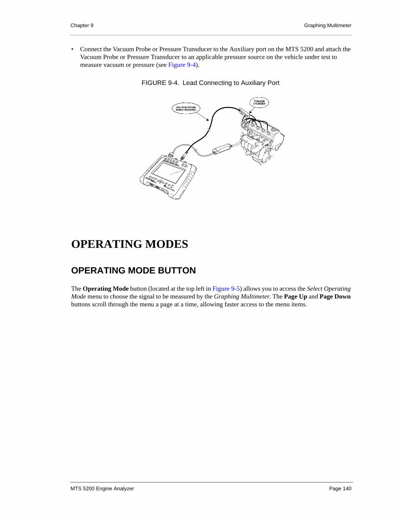
Chapter 9 Graphing Multimeter
• Connect the Vacuum Probe or Pressure Transducer to the Auxiliary port on the MTS 5200 and attach the Vacuum Probe or Pressure Transducer to an applicable pressure source on the vehicle under test to measure vacuum or pressure (see Figure 9-4).
OPERATING MODES
OPERATING MODE BUTTON
The Operating Mode button (located at the top left in Figure 9-5) allows you to access the Select Operating Mode menu to choose the signal to be measured by the Graphing Multimeter. The Page Up and Page Down buttons scroll through the menu a page at a time, allowing faster access to the menu items.
FIGURE 9-4. Lead Connecting to Auxiliary Port
MTS 5200 Engine Analyzer Page 140

Chapter 9 Graphing Multimeter
x
DC Voltage
DC voltage mode measures and displays the DC voltage of a sampled signal. The MTS 5200 can measure DC voltages from 0 - 200 volts.
Frequency
Frequency mode measures and displays the frequency of the sampled signal. The MTS 5200 can measure frequencies from 1 Hz to 200 KHz.
DC Low Current
This mode measures and displays the DC low current value of the sampled signal. The MTS 5200 measures current at the low range of 0 mA to 30 Amps. Use the Low Current Probe for this measurement.
DC High Current
This mode measures and displays the DC high current value of the sampled signal. The MTS 5200 measures current at the higher range of 0 A to 1000 Amps. Use the High Current Probe for this measurement.
Pulse Width
This mode measures and displays the high/low time of a periodic signal. The MTS 5200 allows you to select high time or low time.
Duty Cycle
This mode measures the ratio of the high/low portion of a signal period to the entire signal period and displays the results as a percentage of time. The MTS 5200 allows you to select either the percentage of high or low signal.
FIGURE 9-5. Operating Mode Pop-Up Menus
MTS 5200 Engine Analyzer Page 141

Chapter 9 Graphing Multimeter
Temperature
This mode displays the temperature measured by the Vetronix non-contact IR Temperature Probe. The probe has a temperature range of 32°F to 1000°F with a basic accuracy of 2% of reading and an output of 1mV DC per °F.
You can select either Celsius or Fahrenheit by going to Analyzer Utilities on the Main menu, selecting Setup, and Units of Measure. See Chapter 13.
Pressure
This mode displays the pressure measured by the Vetronix Pressure Transducer. The Pressure Transducer has a measurement range of 0-300 psi. Three different units of measure selections can be used: psi, kPa, or bar. Units of measure are selected in the Units of measure utility located in the Analyzer Utilities/Setup menu. See “Calibration” for Pressure Transducer calibration procedures.
Vacuum
This mode displays the pressure measured by the Vetronix Vacuum Probe. The Vacuum Probe has a measurement range of 30 inHg – 15 psi (0-30 psia). Two different units of measure selections can be used: inHg and mbar. Units of measure are selected in the Units of measure utility located in the Analyzer Utilities/Setup menu. See “Calibration” for Vacuum Probe calibration procedures.
Using the Vacuum Operating Mode
• The Vacuum Operating Mode display uses a split screen. Vacuum is displayed below zero, and pressure is displayed above zero (see Figure 9-6).
• Minimum, Maximum, and Average values for both pressure and vacuum are displayed.
• The live value is displayed at the top of the screen in units of either pressure or vacuum.
• Minimum, Maximum, and Average values remain blank until the sensor measures a pressure or vacuum.
FIGURE 9-6. Vacuum Operating Mode
Zero PressureVacuum Min/Max/Avg
Pressure Min/Max/Avg
MTS 5200 Engine Analyzer Page 142

Chapter 9 Graphing Multimeter
RPM
This mode measures and displays the engine RPM for DI (Distributor Ignition), EI (DIS), and Coil Near Plug (CNP) ignition systems. Figure 9-7 shows a sample screen of the RPM operating mode.
Operating Procedure for Testing RPM
1. Touch the Operating Mode button and select RPM from the Select Operating Mode pop-up menu (see Figure 9-8).
CAUTION
CAUTION!The Vacuum Probe is not designed to measure fluid pressures.
FIGURE 9-7. Example of an EI Vehicle in RPM Meter Mode
FIGURE 9-8. Select RPM Operating Mode
MTS 5200 Engine Analyzer Page 143

Chapter 9 Graphing Multimeter
2. Touch either DI (Dist. Ign.), EI (DIS), or Coil Near Plug (CNP) on the Select Ignition Type pop-up menu (see Figure 9-9).
3. Connect the sync clamp end to any spark plug wire and the BNC end to the SYNC port on the tester. See the lead connecting diagrams in Figure 9-3 on page 139.
4. Correct the sync orientation or change to a different plug wire if the Check Sync Probe message appears at the top of the screen. On certain EI vehicles the Sync Probe may be backwards due to firing polarity.
SETTINGS
UNITS/DIVISION
When choosing the vertical scale of the plot, one of the selections you have is Auto mode. As a measured value increases, this mode automatically changes the vertical scale to prevent the displayed value from moving off the grid. The auto scale function only increases—never decreases— the scale so that the plotted data is always visible on the grid. If the vertical scale is set at a value other than AUTO, auto scaling can be selected by pressing the button until AUTO is displayed.
The vertical axis label changes depending on the Operating mode selected.
NOTE When moving the Sync Probe from cylinder to cylinder or when changing the Sync Probe orientation, you must exit to the Main Menu and re-select RPM from the Graphing Multimeter selection.
NOTEWhen the graph changes its vertical scale, the graph resets along with min/max and average readings and starts back on the left side.
FIGURE 9-9. Select Ignition Type
MTS 5200 Engine Analyzer Page 144
Chapter 9 Graphing Multimeter
TIME/DIVISION
Graphing Multimeter has Time/Div selections ranging from 0.5 sec/div to 50 sec/div. Use the touch screen display buttons or the and keypad buttons to adjust the Time/Div.
Use the longer Time/Div setting for intermittent problem testing. For instance, if a circuit problem occurs intermittently, you might hook the lead to the 5 Volt Reference of the suspected component or circuit and set the Time/Div to 50s. This would allow Graphing Multimeter to monitor the system while you are performing other tasks. When the failure occurs, simply touch the Freeze button to stop the trace and verify the problem.
GLITCH CAPTURE
Glitch Capture enables you to capture and display very short duration voltage spikes. The Glitch On/Off button is located below the Operating Mode button. The current setting is indicated in the upper right of the display screen. Once glitch is selected, the MTS 5200 automatically sets up the Glitch Capture mode. The primary difference between Normal mode and Glitch Capture operation is the active sampling rate. In Normal mode, the sampling rate changes as the Time/Div adjustment is changed. In Glitch Capture mode, the sampling rate is always 6 megasamples/sec.
Glitch Capture is available in DC Voltage, DC Low Current, DC High Current, Vacuum, and Pressure operating modes.
FREEZE
For a description of the Freeze function, see “Freeze” on page 19.
LEAD HELP
The Lead Help button is used to display an example of the connection of the leads for the tester’s current Operating Mode.
POS TRIG / NEG TRIG
The Pos Trig/Neg Trig button allows you to change a rising (Positive) or falling (Negative) trigger for the input signal. The default setting is Negative trigger. The current state is displayed in the upper right hand corner of the screen.
Positive Trigger triggers on a rising edge at a level of 1 volt in all operating modes of the Graphing Multimeter.
MTS 5200 Engine Analyzer Page 145

Chapter 9 Graphing Multimeter
Negative Trigger triggers on a falling edge. The Negative Trigger level depends on the selected Operating Mode:
TIME LOW/HIGH
The Time Low/High button allows you to change calculations to Time Low or Time High in Pulse Width operating mode. The default setting is Time High. The current state is displayed in the upper right hand corner of the screen.
% LOW/HIGH
The % Low/% High button allows you to change calculations to a % Low duty cycle or % High duty cycle. The default setting is % High. The current state is displayed in the upper right hand corner of the screen.
MINIMUM/MAXIMUM/AVERAGE
Graphing Multimeter includes an ongoing minimum, maximum, and average data value. From the start of a measurement until it is frozen or reset, each data value is compared to the existing minimum and maximum value and included in an average calculation.
RESET
When the Graphing Multimeter Reset button is pressed, the minimum, maximum, and average data values and the plotted data are reset and measurement starts over.
OPERATING MODENEGATIVE TRIGGER
LEVEL
Frequency Mode 2 volts
Pulse Width mode 4 volts
Duty Cycle mode 4 volts
MTS 5200 Engine Analyzer Page 146
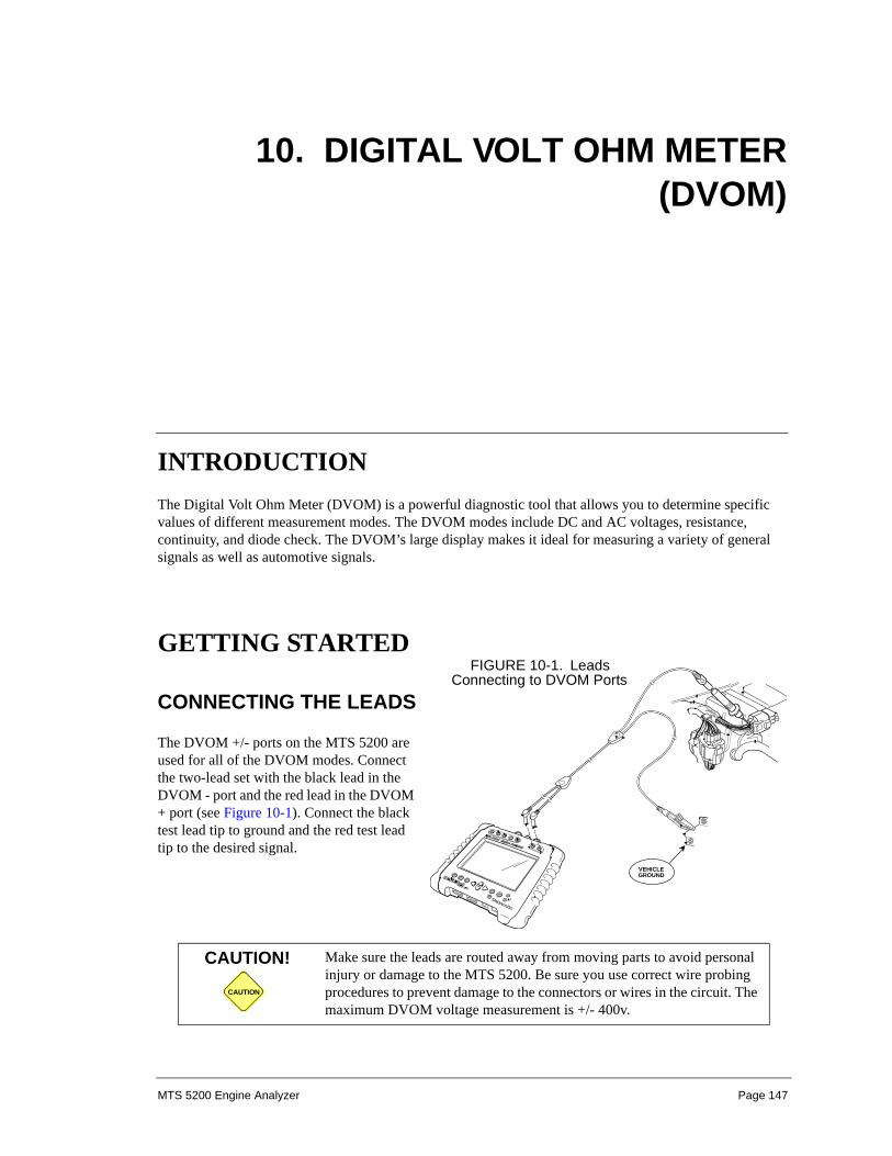
10. DIGITAL VOLT OHM METER(DVOM)
INTRODUCTIONThe Digital Volt Ohm Meter (DVOM) is a powerful diagnostic tool that allows you to determine specific values of different measurement modes. The DVOM modes include DC and AC voltages, resistance, continuity, and diode check. The DVOM’s large display makes it ideal for measuring a variety of general signals as well as automotive signals.
GETTING STARTED
CONNECTING THE LEADS
The DVOM +/- ports on the MTS 5200 are used for all of the DVOM modes. Connect the two-lead set with the black lead in the DVOM - port and the red lead in the DVOM + port (see Figure 10-1). Connect the black test lead tip to ground and the red test lead tip to the desired signal.
CAUTION
CAUTION! Make sure the leads are routed away from moving parts to avoid personal injury or damage to the MTS 5200. Be sure you use correct wire probing procedures to prevent damage to the connectors or wires in the circuit. The maximum DVOM voltage measurement is +/- 400v.
VEHICLEGROUND
FIGURE 10-1. Leads Connecting to DVOM Ports
MTS 5200 Engine Analyzer Page 147

Chapter 10 Digital Volt Ohm Meter (DVOM)
Once you select DVOM from the Main menu, a message appears reminding you to use the DVOM inputs (Figure 10-2). Always use the DVOM ports for the DVOM application.
OPERATING MODESThere are five operating modes in the DVOM application, as shown in Figure 10-3.
WARNING! The MTS 5200 is not intended for testing 110V, AC electrical circuits. Do not plug the leads into an electrical wall socket. Damage to the tester or personal injury may occur.
FIGURE 10-2. DVOM Lead Connection Message
FIGURE 10-3. DVOM Select Operating Mode Display
MTS 5200 Engine Analyzer Page 148

Chapter 10 Digital Volt Ohm Meter (DVOM)
DC VOLTAGE
DC voltage mode displays the DC voltage of a sampled signal in the DVOM. The MTS 5200 can measure DC voltage from 0 mV to ±400 V.
AC VOLTAGE
AC voltage mode displays the AC RMS voltage of a sampled signal in the DVOM. The MTS 5200 can measure AC RMS voltage from 0 mV to 400 V. The measured signal is a RMS voltage reading.
FIGURE 10-4. DVOM DC Voltage Display
FIGURE 10-5. Range Selections for DVOM DC Voltage
MTS 5200 Engine Analyzer Page 149

Chapter 10 Digital Volt Ohm Meter (DVOM)
RESISTANCE
Resistance mode displays the impedance in a circuit. The measurement can be taken at different ranges, or you can let the MTS 5200 automatically set the range.
CONTINUITY
Continuity mode displays the continuity of a connection as follows:
An audio beep also sounds when a connection is measured to be closed or shorted.
DIODE CHECK
The Diode Check displays the forward voltage across a diode in the DVOM. The tester sends a small current through the diode to test the voltage. Depending on the diode type, the voltage should be about 0.300 to 0.700 Volts.
Open Circuit is displayed when the diode is defective or when the test leads are reversely connected across the diode. If you are not certain about the polarity of the diode, reverse the test lead connection. If Open Circuit is still displayed, the diode is defective. A functioning diode must display Open Circuit when connected in reverse.
OPEN CIRCUIT If the connection is open or interrupted
LESS THAN 400 OHMS (APPROX.) If the connection is closed or shorted.
FIGURE 10-6. Range Selections for DVOM Resistance
MTS 5200 Engine Analyzer Page 150
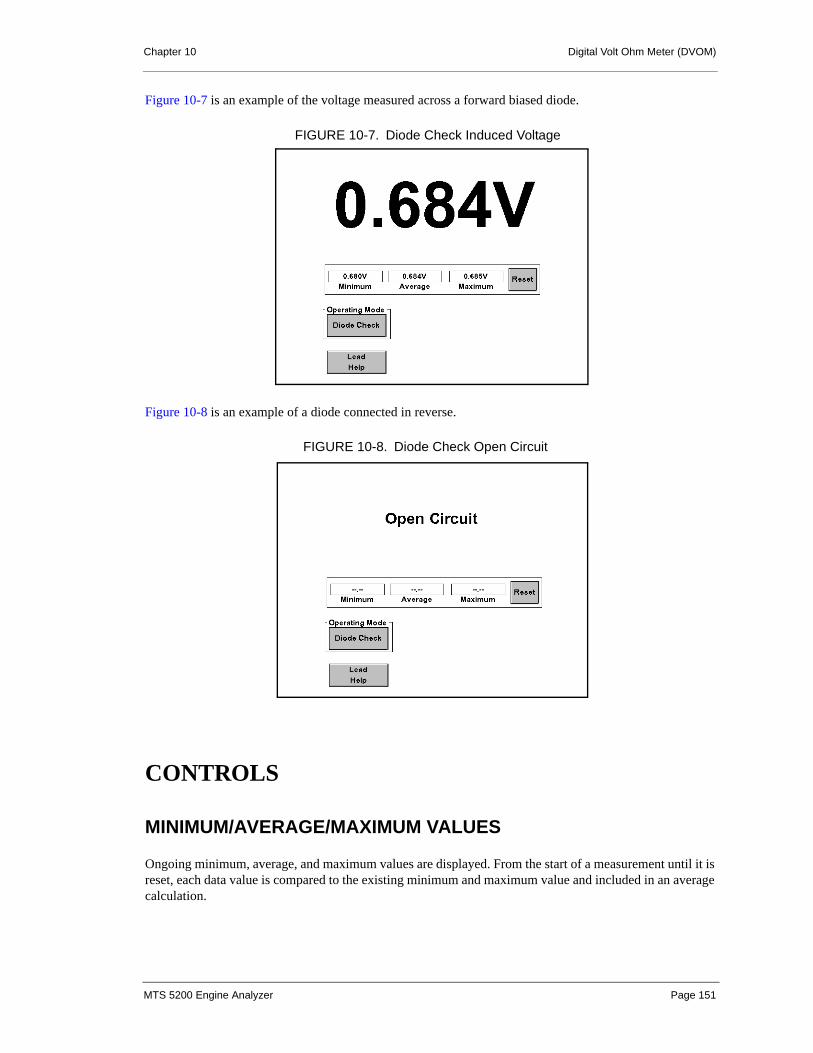
Chapter 10 Digital Volt Ohm Meter (DVOM)
Figure 10-7 is an example of the voltage measured across a forward biased diode.
Figure 10-8 is an example of a diode connected in reverse.
CONTROLS
MINIMUM/AVERAGE/MAXIMUM VALUES
Ongoing minimum, average, and maximum values are displayed. From the start of a measurement until it is reset, each data value is compared to the existing minimum and maximum value and included in an average calculation.
FIGURE 10-7. Diode Check Induced Voltage
FIGURE 10-8. Diode Check Open Circuit
MTS 5200 Engine Analyzer Page 151

Chapter 10 Digital Volt Ohm Meter (DVOM)
RESET
When the Reset button is pressed, the minimum, average, and maximum data values are reset and measurement starts over.
MEASUREMENT RANGE
You may set Auto Range or a series of fixed ranges. If a reading is outside of a specifically selected range, only zeroes are displayed. Auto Range indicates that the MTS 5200 automatically finds the best range for measuring the input signal. The fixed ranges allow for accurate measurements in a set range.
MTS 5200 Engine Analyzer Page 152

11. SNAPSHOT
INTRODUCTIONThe Snapshot function gives you the ability to capture, save, and playback a length of data collected from a vehicle. When a snapshot is captured, the MTS 5200 collects data from the vehicle for a length of time you select. Snapshots can be played back in real time or carefully examined by scrolling through the snapshot manually.
Snapshots can be captured and played back in Secondary Ignition, Primary Ignition, 4-Channel Oscilloscope, Graphing Multimeter, and Vacuum Waveform modes. Snapshots that are captured in Primary/Secondary Ignition or Vacuum Waveform can be played back in any Display Mode you choose, thus allowing a great deal of flexibility when examining waveforms.
SETTING UP A SNAPSHOT
When the Snapshot button is selected, the Snapshot Setup screen displays (Figure 11-1):
MTS 5200 Engine Analyzer Page 153

Chapter 11 Snapshot
On the Snapshot Setup screen you can configure the trigger point and the length of the snapshot.
TRIGGER POINT
Use the Trigger Point setting to identify the point in time that you want the tester to collect data. The MTS 5200 has an adjustable trigger point that allows you to capture as much pre- or post-trigger data as you want.
Adjusting Trigger Point
Pre- and post-trigger times are adjusted with the “Right” and “Left” arrow buttons on either the touch screen or the keypad. The pre-trigger setting is displayed on the left side of the Trigger Point adjustment bar and is displayed in seconds. Negative values indicate pre-trigger. The post-trigger setting is displayed on the right side of the Trigger Point adjustment bar and is displayed in seconds. Positive values indicate post-trigger.
SNAPSHOT LENGTH
You can adjust the total length of the snapshot to be able to capture any type of problem. The available time differs depending on the Operating Mode in which you are capturing the snapshot. A Maximum selection is available which allows you to capture data until the tester runs out of storage space.
NOTE Before entering the Snapshot mode, adjust the settings so the waveform you are going to capture is easily viewable. Time/Div, Volts/Div, etc. are not adjustable while a snapshot is being captured.
NOTESome types of snapshots require more memory than other. In some cases the available storage space is filled before the selected length is reached.
FIGURE 11-1. Snapshot Setup Screen
MTS 5200 Engine Analyzer Page 154

Chapter 11 Snapshot
Adjusting Snapshot Length
Snapshot Length is adjusted with the “Up” and “Down” arrows on either the touch screen or the keypad.
CONTINUE/CANCEL
When you have completed your Snapshot Setup options, touch Continue to proceed to the Snapshot mode where a snapshot can be captured.
Touch Cancel to return to the previous screen and cancel any settings you may have just entered.
CAPTURING A SNAPSHOTOnce the settings have been configured in the Snapshot Setup screen (Figure 11-1), and you touch Continue, you enter Snapshot mode where you can capture data using the Snapshot menu (Figure 11-2).
SNAPSHOT CONTROLS
Main Menu
The Main Menu button returns you to the main menu of the operating mode from which you accessed Snapshot mode.
NOTE When the Snapshot menu is displayed, the keypad arrow buttons are disabled. Additionally, when the tester is recording or ready to record, operating mode display controls (such as Volts/Div, Time/Div, Display Mode, etc.) are either removed from the menu or disabled. No adjustment to the waveform is allowed during snapshot capture.
FIGURE 11-2. Snapshot Menu
MTS 5200 Engine Analyzer Page 155

Chapter 11 Snapshot
Trigger/Stop
This button toggles between Trigger and Stop. Touching Trigger marks the trigger point for the recording, which you have pre-selected in the Snapshot Setup screen (see “Trigger Point” on page 154). Once the recording is triggered, the button name changes to Stop.
The recording continues for as long as the Snapshot Length you pre-selected in the Snapshot Setup screen (see “Snapshot Length” on page 154). However, you can use the Stop button to force the recording to stop before the selected time has expired. The Enter button on the keypad activates the Trigger/Stop button.
As soon as a snapshot has been captured, the tester enters the Playback mode.
RECORDING INDICATOR
In the top left corner of the grid there is a text box that displays the status of the snapshot.
One beep is sounded when a snapshot has been triggered. Two beeps are sounded when the recording is complete.
PLAYBACK MODEYou view snapshots from Playback mode, which you enter when a snapshot has been captured or when a saved snapshot file is selected for viewing from the File Manager.
Selecting File in Memory
If you use the File Manager to select a snapshot file located in memory, use the following procedure:
1. Touch Analyzer Utilities on the Main menu, then press File Manager or touch the File List button on the Playback menu.
2. Select the snapshot to be viewed.
Once a snapshot is selected, the applicable operating mode is opened in Playback mode.
3. Touch the Exit keypad button or the File List button to display the snapshot section of the File Manager.
The MTS 5200 is ready for a trigger.
The snapshot has been triggered.
MTS 5200 Engine Analyzer Page 156

Chapter 11 Snapshot
PLAYBACK CONTROLS
The Playback menu (see Figure 11-3) contains the control buttons for playing a snapshot.
Snapshot
The Snapshot button exits the Playback Mode and returns to the Snapshot menu where another snapshot can be captured. The Exit keypad button operates the Snapshot button as well. If an unsaved snapshot exists when the Playback Mode is exited, you are prompted to either save the snapshot to memory or disregard the snapshot.
Play/Stop
The Play/Stop toggle button starts and stops the real time playback of the snapshot. Once the Play button is pressed, the button changes to the Stop button.
Touching the Play button starts the playback of the snapshot from the beginning of the file. The snapshot file plays back exactly as it was recorded.
The Stop button stops the playback and returns the snapshot to the beginning of the file. When the Stop button is pressed, it changes back to the Play button.
Freeze/Run
This button toggles between Freeze and Run. During snapshot playback the Freeze button pauses the playback. When the Freeze button is touched, it changes to Run. Then touch the Run button to continue playback from the point at which it was paused.
The Enter button on the keypad controls the Freeze/Run button.
FIGURE 11-3. Playback Menu
MTS 5200 Engine Analyzer Page 157

Chapter 11 Snapshot
File List
This button takes you to the snapshot section of the File Manager, where all saved snapshots from all operating modes are listed and available for playback. The File List button is only available when viewing a snapshot from the File Manager.
Save
The Save button allows you to either save the complete snapshot to memory or extract single screen captures from the snapshot in bitmap format. Only one snapshot can be saved for each operating mode.
Once the Save button is pressed, the Save Options menu is displayed (see Figure 11-4). This menu offers the following selections:
Save Snapshot: This selection saves the complete snapshot to memory where it can be recalled and viewed from the File Manager.
Save Current Screen: This selection saves the screen that the snapshot file is displaying at the current time. The screen capture is saved as a bitmap.
When a snapshot or screen capture is saved, the Edit Notes screen is displayed, which allows the user to attach any notes about the file that is being saved. These notes are saved along with the file and can be viewed in the detail view of the File Manager.
Keypad Arrow Buttons
When the Playback menu is displayed, the keypad arrow buttons operate the playback controls.
Right Arrow ( ): Moves forward through the snapshot one frame at a time each time the arrow button is pressed.
Left Arrow ( ): Moves backward through the snapshot one frame at a time each time the arrow button is pressed.
FIGURE 11-4. Save Options Menu
MTS 5200 Engine Analyzer Page 158

Chapter 11 Snapshot
Up Arrow ( ): Jumps forward through the snapshot in increments of one-fifth of the total length of the snapshot each time the arrow button is pressed.
Down Arrow ( ): Jumps backward through the snapshot in increments of one-fifth of the total length of the snapshot each time the arrow button is pressed.
ADJUSTING SETTINGS DURING PLAYBACK
During playback you are allowed to adjust some of the operating mode settings. The following list identifies the adjustments that are available in each operating mode:
Graphing Multimeter
• Volts/Division
4-Channel Oscilloscope
• AC vacuum smoothing
• Cursor selection
Vacuum Waveform
• Smoothing
• Display mode
• Units/Div
Primary/Secondary Ignition
• Volts/Division
• Display Mode
PROGRESS INDICATOR
The playback progress indicator is a numeric display in the upper right corner of the grid area which shows the total time (in seconds) of the snapshot and the segment of the file currently being viewed. For instance, if you are viewing 1.100 seconds into a 95.090 second snapshot, the display shows “1.100/95.090”.
NOTE The scrolling buttons are fully functional in the 4-Channel Oscilloscope at Time/Div settings of 100 ms and faster and in the Ignition and Vacuum Waveform modes. When viewing Graphing Multimeter and 4-Channel Oscilloscope snapshots that were recorded at a Time/Div setting slower than 100 ms/Div, only the Forward scroll button is active.
NOTE EI Secondary Ignition snapshots can only be played back in the Power/Waste Comparison Display mode if they were originally recorded in the Power/Waste Comparison Display mode.
MTS 5200 Engine Analyzer Page 159

Chapter 11 Snapshot
If the snapshot was recorded with pre-trigger data, the time before the trigger is displayed as a negative number. “0” represents the trigger point, and post-trigger data is displayed as a positive number.
WARNING MESSAGES
UNSAVED SNAPSHOT
If a snapshot exists in the buffer and you attempt to exit Playback mode without saving, the following message appears:
Yes: Saves the current snapshot to internal memory and takes you to the Edit Notes screen. There you can enter notes for the snapshot.
If a snapshot from the same mode already exists in internal memory, you are asked if you want to overwrite the existing file (see “Overwrite Saved Snapshot” on page 161).
No: Causes the message to disappear and takes no action.
FIGURE 11-5. Save Snapshot Message
MTS 5200 Engine Analyzer Page 160
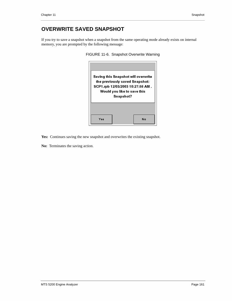
Chapter 11 Snapshot
OVERWRITE SAVED SNAPSHOT
If you try to save a snapshot when a snapshot from the same operating mode already exists on internal memory, you are prompted by the following message:
Yes: Continues saving the new snapshot and overwrites the existing snapshot.
No: Terminates the saving action.
FIGURE 11-6. Snapshot Overwrite Warning
MTS 5200 Engine Analyzer Page 161

12. FILE MANAGER
INTRODUCTIONThe file management system of the MTS 5200 allows you to view and manipulate saved image, snapshot, and text files by using the following functions:
• Viewing saved files
• Deleting one or multiple files
• Viewing detail information about a file
• Adding information about a file
• Formatting internal Flash
• Searching files for key words
• Upload screen captures (bitmaps) and FCI test log files to a PC
You access the file management system by touching Analyzer Utilities on the Main menu and selecting File Manager.
MTS 5200 Engine Analyzer Page 162

Chapter 12 File Manager
FILE NAMING CONVENTION
The names of all files are created using the following conventions:
1. The first three characters of the name represent the operating mode of the captured file:
• CBT = Cylinder Balance Test
• CKK = Cranking kV Test
• FCI = Failed Cylinder ID Test
• GMM = Graphing Multimeter
• IGN = Ignition
• SCP = 4-Channel Oscilloscope
• VAC = Vacuum Waveform
2. The next two characters are the number assigned to the file.
• Each mode (IGN, GMM, VAC, SCP, etc.) can have multiple bitmap files (for instance, GMM1 through GMM12).
• Each mode (IGN, GMM, VAC, SCP, etc.) can have only 1 snapshot file in memory.
3. File extensions used are as follows:
• .bmp = bitmap files
• .rpb = snapshot files
• .prt = FCI Test Log files
CAPACITY/FREE SPACE/TOTAL FILES INDICATOR
The File Manager displays in the lower left portion the total capacity, free space, and total number of files.
FIGURE 12-1. List View Screen
MTS 5200 Engine Analyzer Page 163

Chapter 12 File Manager
Capacity: This indicates the total capacity of the bitmap or snapshot FCI Test Log memory. The bitmap and FCI Test Log memory has a total capacity of 748K bytes, and the snapshot memory has a total capacity of 1270K bytes.
Free Space: This indicates the unused space that is available for saving.
Total Files: This indicates the total number of files that are saved to memory.
FILE MANAGER CONTROLSThe following buttons appear on the screens in the File Management system when the File Manager button on the Utilities Menu is touched. They are used to view and edit the files that are saved in memory.
• Detail View/List View
• View File
• Edit Notes
• FCI
• Snapshot/Bitmap/FCI
• Utilities Menu
DETAIL VIEW/LIST VIEW
The List View button displays just the filename of each file, allowing more files to be viewed on one screen.
The Detail View button displays the detailed information about each file:
• file name
• vehicle information (selected from the database or manually selected)
• date and time the file was saved
• notes (as entered in the Edit Notes or VIN/Notes screen)
• length of snapshot (in seconds) for snapshot files
When in the detail view mode, the button title changes to List View to enable you to return to the List View screen. A maximum of three files is displayed on a screen. The “Up” and “Down” arrow buttons ( and ) scroll through the list one file at a time. The Page Up and Page Down buttons scroll through the page three files at a time. Use these keys to scroll through the file list, then select a file and press the View File button (or Enter keypad button) to view the selected file.
MTS 5200 Engine Analyzer Page 164

Chapter 12 File Manager
VIEW FILE
The View File button lets you display the saved bitmap, snapshot, or FCI Test Log files. This function is available in both the List View and Detail View screens. If you select a snapshot, the file is displayed in the Playback mode of the applicable operating mode.The Enter button also operates the View File button. (See “Playback Mode” on page 156.)
EDIT NOTES
The Edit Notes function lets you input or delete text in the Notes field of the file. After you select a file name on either the List View or Detail View screen, touch the Edit Notes button to access the Edit Notes screen (see Figure 12-3):
FIGURE 12-2. Detail View
FIGURE 12-3. Edit Notes Screen
MTS 5200 Engine Analyzer Page 165
Chapter 12 File Manager
At the top of the Edit Notes screen are the following:
File Name: Name of the file you selected on the List View or Detail View screen.
Vehicle Information: The information you have selected from the database or manually selected.
Notes: The text (if any) previously entered on the Edit Notes screen. If no text has been entered, the default is the name of the operating mode in which the file was created.
The blinking cursor is positioned at the end of the text string in the Notes field. You may begin entering additional text, or you can use the Backspace button to delete the previous character(s) from the field. The Notes field can have a maximum of 50 characters.
Use the keyboard buttons on the screen to enter text. The Shift Key button displays the upper case letters or symbol counterparts, as on a standard keyboard. Note, however, that the Shift Key acts as a lock and must be touched a second time to revert to the lower case character set.
The Enter key on the keyboard (and the Enter key on the keypad) inputs your notes and returns you to either the List File screen or the Detail File screen.
SNAPSHOT/BITMAP/TEXT
These buttons toggle between Snapshot, which causes all the snapshot file names (.rpb) to be displayed, Bitmap, which causes all the bitmap file names (.bmp) to be displayed, and FCI, which causes all the FCI Test Log Files (.prt) to be displayed.
The default view is Bitmap, at which time the two buttons then read Snapshot and FCI. When one of these buttons is selected, the name changes to whatever mode was last viewed. Thus, the buttons will always be labeled with the two modes which are not currently being viewed.
UTILITIES MENU
Touching the Utilities Menu button causes the alternate set of buttons to appear, which includes:
• Search
• TechView Upload
• Format Flash
• Delete
• File Menu
MTS 5200 Engine Analyzer Page 166

Chapter 12 File Manager
UTILITIES MENU CONTROLSThe following buttons appear on the screens in the File Management system when the Utilities Menu button on the File Menu is touched (see Figure 12-4). They provide utilities to manage the files saved in the system. See also “File Manager Controls” .
SEARCH
The Search function allows you to search through all the information about the saved files—file name, vehicle information, notes—using one or more keywords to find a specific file or files.
If you enter more than one keyword, separate each word with a space. The search matches any word within the keyword string. For instance, if you enter “cylinder failure”, your results will include any file in which the string “cylinder failure” occurs as well as any file containing the word “cylinder” or the word “failure”.
FIGURE 12-4. Utilities Menu Buttons
FIGURE 12-5. Search Function Screen
MTS 5200 Engine Analyzer Page 167

Chapter 12 File Manager
The keyboard to enter the search criteria is similar to that used to enter notes (see “Edit Notes” ). The characters on the keyboard, however, are not case sensitive, that is, “Cylinder”, “cylinder”, and “CYLINDER” are treated the same.
Touch the Enter button on the screen or press the Enter button on the keypad to activate the search.
The results of the search appear on the Search Results Detail View screen, which is similar to the detail screen for the File Manager Detail View screen (see Figure 12-2). You can touch the List View button to see a list of matched file names only. All of the File Management functions are available on the search result screens.
Two buttons are available on the Utilities Menu of the search result screens. Touch the Utilities Menu button to activate them.
Cont. Search: Lets you continue searching by entering new text to search only those files which matched the first search. You are able to enter a total of 15 search levels.
New Search: When you are viewing search results, the Search button changes to New Search.
If no matches are found, an error message appears stating that “No files found that match your search criteria.” Touch the OK button to return to the Search Function screen.
Press the keypad Exit key to return to the List View screen or Detail View screen.
TECHVIEW UPLOAD
The TechView Upload button is used to upload bitmap files from the MTS 5200 to the TechView 5200 PC application. It functions only if you have the TechView 5200 software installed on your system. Pressing the TechView Upload button opens the TechView 5200 Upload screen. This puts the MTS 5200 into the upload mode and allows bitmap files to be transferred to the TechView 5200 PC application. See the Upload Images section of the TechView 5200 help file for further information.
NOTE The TechView 5200 Upload screen is not used to upload bitmaps to your PC using the File Transfer Utility (FTU). See Chapter 14. At this time only bitmaps can be uploaded to the PC with TechView Pro.
MTS 5200 Engine Analyzer Page 168

Chapter 12 File Manager
FORMAT INTERNAL FLASH
This button allows you to format the internal Flash memory and erase all files. You are warned that formatting causes all saved files to be lost (see Figure 12-6).
DELETE
This function allows you to delete a single file or multiple files. Touch the filename(s) on the List View or Detail View menu, then touch the Delete button on the Utilities Menu. An information message screen appears showing the number of files selected and asking you to confirm the deletion. Touch OK.
FILE MENU
Touching this button causes the File Menu set of buttons to appear (see “File Manager Controls” on page 164).
FIGURE 12-6. Format Flash Warning Message
FIGURE 12-7. Delete Screen with Confirmation Message
MTS 5200 Engine Analyzer Page 169

Chapter 12 File Manager
WARNING MESSAGES
INTERNAL FLASH FULL
When the internal Flash memory capacity is full, a pop-up message informs you and directs you to delete unwanted files. Use the Delete button (see “Delete” on page 169) to selectively delete files, or use the Format Flash button (see “Format Internal Flash” on page 180) to erase all files from memory.
FILE CORRUPTION DETECTED
During the boot up process the MTS 5200 checks saved bitmap and snapshot files for corruption. If a saved bitmap or snapshot file become corrupted, an error message is displayed as soon as the tester completes the boot up process. See Figure 12-9.
Files can become corrupted if the tester is powered down improperly or reset during the file saving process.
FIGURE 12-8. Internal Flash Full Warning Message
FIGURE 12-9. File Corruption Warning Message
MTS 5200 Engine Analyzer Page 170

Chapter 12 File Manager
In the unlikely event that a file becomes corrupted, the internal flash memory must be formatted to remove the bad file. Before the internal flash memory is formatted, you can view the files that are saved and upload any files you want to keep. When all of the files you want to keep have been uploaded to the PC, the internal flash must be formatted. See “Format Internal Flash” on page 169 or “Format Internal Flash” on page 180.
NOTEIf the tester is powered down improperly, files may become corrupted or lost completely.
MTS 5200 Engine Analyzer Page 171

13. ANALYZER UTILITIES
Analyzer Utilities allow you to view and adjust the system settings, perform diagnostic self tests of the software and hardware, manage battery charging, and various other functions. From the Main menu touch the Analyzer Utilities button. This brings up the Analyzer Utilities menu which has three selections: Setup, Tools, and File Manager (see Chapter 12).
FIGURE 13-1. Utilities Menu
MTS 5200 Engine Analyzer Page 172

Chapter 13 Analyzer Utilities
SETUP
SET DATE AND TIME
The MTS 5200 utilizes a date and time function in memory as part of its software function. Date and time are used to put a time stamp on files that are recorded and saved. To set the time and date, simply touch the Set Date and Time button, bringing up the Set Date/ Set Time menu. Touch the month and you will notice that fonts start to blink on and off. Touch the < > to move forward or backward one month at a time, or you can touch the << >> to make larger jumps forward or backward. All the settings in the Date/Time function follow the same procedure. When you have finished the setup, touch the Save button to save the settings to memory. Touching the Revert button will set the Time/Date function back to the original setting when the unit was powered up. Once you have set the date and time, press the EXIT keypad button to return to the Setup menu.
FIGURE 13-2. Utilities Setup Menu
FIGURE 13-3. Set Date and Time Menu
MTS 5200 Engine Analyzer Page 173

Chapter 13 Analyzer Utilities
SELECT LANGUAGE
The Select Language option displays the available languages in a list box, on which you select the desired language by touching its name.
Once you select a language, the analyzer continues to display that language, even after the tester is turned off and back on, until another is selected
CONFIGURE NETWORK IP ADDRESS
The IP Address and the IP Mask are used for configuring Shop Foreman.
MEASUREMENTS AND SETTINGS
The Measurements and Settings screen allows you to select Units of Measure and settings for the Cranking Test and the Ignition Disable Duration:
FIGURE 13-4. Measurements and Settings Screen
MTS 5200 Engine Analyzer Page 174

Chapter 13 Analyzer Utilities
Units of Measure
This selection allows you to choose the units of measurement for different operating modes (see Figure 13-5). When a unit is selected in this screen, it is used in all applicable test modes on the tester. Changes in units of measure affect Graphing Multimeter, Vacuum Waveform, 4 Channel Oscilloscope, Failed Cylinder ID test, and Cylinder Balance test.
To change the units/div setting, press the units that you wish to use for measurement (selected units appear shaded), then press the Done button. Pressing the Cancel button exits the Units of Measure screen and reverts the settings to the state they were in before you entered Units of Measure.
The following selections are available in the Units of Measure screen:
Temperature Probe Units – °C, °F
Pressure Transducer Units – psi, kPa, bar
Vacuum Probe Units – inHg, bar
FCI Units - English, Metric
Cranking Test Setup
For an explanation of this function, see “Setup” on page 101.
Ignition Disable Duration
For an explanation of this function, see “Setting Ignition Disable Duration” on page 111.
FIGURE 13-5. Units of Measure Menu
MTS 5200 Engine Analyzer Page 175

Chapter 13 Analyzer Utilities
TOOLS
SOFTWARE VERSION NUMBER
Software Version displays internal MTS 5200 software information. The internal software version number and release date are displayed on the SW Version button. Once pressed the following information is displayed in the S/W Version Information screen:
• Application: Displays the version number, the release date, and release time of the software containing all features and functions.
• Boot: Displays the version number, the release date, and release time of the software that is used to start up the tester.
• DVOM: Displays the version number, the release date, and release time of the software that is used in the Digital Voltage Ohm Meter.
• Ethernet Address
• Language: Version number and release date of each language on the tester.
FIGURE 13-6. Utilities Tools Menu
MTS 5200 Engine Analyzer Page 176

Chapter 13 Analyzer Utilities
SELF TESTS
This feature allows for testing of the LCD display, touch screen, and communication ports. To use the Self Tests, touch the Self Test button bringing up a sub menu displaying the Self Tests functions.
RS-232: Com 1: Test
The RS-232 Communication test checks for proper operation of the RS-232 serial data hardware on the tester. Press the RS-232 Com 1 Test to run the communication port 1 test. A screen prompting you to install the Com 1 Port Test Adapter (Figure 13-7) to the COM 1 port is displayed. Install the adapter, then follow the instructions on the screen to complete the test. The test indicates either PASS or FAIL.
RS-232: Com 2: Test
The RS-232 Communication test checks for proper operation of the RS-232 serial data hardware on the tester. Press the RS-232 Com 2 Test to run the communication port 2 test. A screen prompting you to install the Com 2 Port Test Adapter (Figure 13-7) to the COM 2 port is displayed. Install the adapter, then follow the instructions on the screen to complete the test. The test indicates either PASS or FAIL.
LCD Test
Touch LCD Test to begin the LCD Test. Once the LCD test mode is entered, the display switches between black and white displays. This allows you to visually check the display for any faulty pixels. To cancel the test, simply touch the screen.
TouchScreen Test
Touch the TouchScreen Test button to begin the test. Touch each of the corner buttons. If any button does not respond, recalibrate the touch screen (see “Calibrate Touch Screen” on page 178). Touch the Exit button to leave the Touch Screen Test function.
CALIBRATION
This feature allows you to perform calibrations of the Vacuum Probe, Pressure Transducer, Touch Screen, and the Auxiliary port. To use the calibration feature, touch the Calibration button, which brings up a submenu displaying the Calibration Functions (see Figure 13-8).
CAUTION
CAUTION!Do not use sharp objects (such as a screw driver) when touching the screen surface.
FIGURE 13-7. RS-232 Self-Test Adapters
MTS 5200 Engine Analyzer Page 177

Chapter 13 Analyzer Utilities
Calibrate Vacuum Probe
This selection allows you to calibrate the Vacuum Probe. When calibrating the Vacuum Probe, observe the following precautions to ensure an accurate calibration:
• Make sure the Vacuum Probe cable is connected to the auxiliary port of the MTS 5200.
• Make sure the Vacuum Probe cable is connected to the Vacuum Probe.
• Ensure that the Vacuum Probe is not connected to any source of pressure or vacuum. The Vacuum Probe should be exposed to ambient air pressure during the calibration process.
Calibrate Pressure Transducer
This selection allows you to calibrate the Pressure Transducer. When calibrating the Pressure Transducer, observe the following precautions to ensure an accurate calibration:
• Make sure the Pressure Transducer cable is connected to the auxiliary port of the MTS 5200.
• Make sure the Pressure Transducer cable is connected to the Pressure Transducer.
• Ensure that the Pressure Transducer is not connected to any source of pressure. The Pressure Transducer should be exposed to ambient air pressure during the calibration process.
Calibrate Touch Screen
Selecting the Touch Screen Calibration button brings up an instruction window that tells you how to calibrate the touch screen.
To calibrate the MTS 5200’s touch screen, do the following:
1. Turn the unit off.
2. Press and hold the Enter button.
3. Turn the unit on.
4. Release Enter button when the message appears instructing you to release the button.
FIGURE 13-8. Calibration Menu
MTS 5200 Engine Analyzer Page 178
Chapter 13 Analyzer Utilities
5. Select Calibrate TOUCH SCREEN.
6. Touch repeatedly each of the four corner targets on the screen until the plus sign disappears and the box turns gray. After the last, the MTS 5200 indicates it is calibrating, following which you are returned to the utilities menu.
7. Touch Exit to return to the MTS 5200 Main menu.
Calibrate Auxiliary Port
This selection allows you to calibrate the auxiliary port of the MTS 5200. To perform this calibration procedure, you must have the auxiliary port loop-back connector.
This calibration procedure only needs to be performed once during the life of the tester and is only necessary if you use the Vacuum Probe or the Pressure Transducer measurements. When calibrating the auxiliary port, observe the following precautions to ensure an accurate calibration:
• Disconnect all test leads from the tester.
• Attach the auxiliary port loop-back connector to the auxiliary port of the tester.
• Apply external power to the tester.
The auxiliary port loop-back connector (PN – 06007156) is supplied with the Vacuum Probe and/or Pressure Transducer kits.
Primary Ignition
This selection allows you to calibrate the primary ignition port of the MTS 5200.
This calibration procedure only needs to be performed once during the life of the tester. When calibrating the primary ignition port, observe the following precautions to ensure an accurate calibration:
• Disconnect all test leads from the tester.
• Press OK to begin calibration.
You are informed when calibration is complete.
CHARGE BATTERY
To charge the battery pack, connect the tester to a 12 VDC power source such as the vehicle battery or the 12-volt AC/DC power supply. You must select Start Battery Charging from the Analyzer Utilities/Tools/Charge Battery screen to start battery charging. It is important that you let the MTS 5200 complete its battery charge cycle every time the battery is charged; this will extend the life of the battery pack.
It takes approximately 20 minutes to fast charge the battery pack to 85% of full charge, and approximately 2 hours to top off the battery pack to 100% charged. In order for the battery to charge, the external power supply voltage needs to be between 8 and 16 volts DC.
CAUTION
CAUTION!Do not use sharp objects (such as a screw driver) when touching the screen surface.
MTS 5200 Engine Analyzer Page 179

Chapter 13 Analyzer Utilities
FORMAT INTERNAL FLASH
This button allows you to format the internal Flash memory and erase all files. You are warned that formatting causes all saved files to be lost (see Figure 13-9).
ENABLE IGNITION DEMONSTRATION
The Enable Ignition Demonstration function allows for selection of a stored ignition waveform program. This program operates in DI Secondary Ignition, Secondary Quick Check, and Primary Ignition. This allows you to get better acquainted with the Engine Analyzer controls, allowing for smoother operation when hooked to a vehicle.
Access the stored waveform by selecting Analyzer Utilities on the Main menu, then touching the Tools button. Touch Enable Ignition Demonstration, and the waveform program is made available to DI Secondary Ignition, Secondary Quick Check, and Primary Ignition. Press the Exit button twice to return to the Main menu, then access the operating mode you want. A sample, ideal waveform is displayed, and you are able to access the different functions in the selected operating mode and see the effect on the waveform.
To turn the Ignition Demonstration off, press Disable Ignition Demonstration.
NOTEThe power button illuminates green when the battery is charging and turns amber or red when the state of charge is low.
NOTE After 5 minutes of no activity the LCD back light turns off to conserve the battery. Touching the screen or making a selection turns the backlight on again.
FIGURE 13-9. Format Flash Warning Message
MTS 5200 Engine Analyzer Page 180

Chapter 13 Analyzer Utilities
FILE MANAGERSee “File Manager” on page 162
MTS 5200 Engine Analyzer Page 181

14. FILE TRANSFER UTILITY,VERSION 1.4
UPLOADING FILESUse the File Transfer Utility (FTU) to upload the saved bitmap files that are in the MTS 5200 Engine Analyzer.
To upload the saved files from the MTS 5200, do the following:
1. Put tester in Download mode by pressing the Analyzer Utilities button on the Main menu and then selecting the Tools button.
2. Connect the PC interface cable from your computer's COM port to COM 2 on the MTS 5200.
3. Click the Upload Tester Files toolbar button in the MTS 5200 File Transfer Utility program, or select Upload Tester Files from the File menu.
The Setup dialog appears.
FIGURE 14-1. Upload Tester Files Button
FIGURE 14-2. Setup Dialog
MTS 5200 Engine Analyzer Page 182

Chapter 14 File Transfer Utility, Version 1.4
To begin the upload process, follow the directions on the Setup Dialog:
1. If you have not already done so, connect the RS232 cable to the PC serial port.
2. Connect the other end of the RS232 cable to COM 2 on the MTS 5200.
3. Power up the tester and select Tools from the Analyzer Utilities menu.
4. Click the OK button on the Setup dialog to begin the upload process.
The Upload Screen shows the progress of the operation.
Once all of the files are uploaded, the File Transfer Utility displays a message indicating that the upload is complete.
VIEWING UPLOADED FILESTo view any uploaded bitmap file, do the following:
1. Double-click the file in the file list. This launches whatever program is set as the .BMP file viewer on your computer.
To change the bitmap file viewer, do the following:
1. Launch Windows Explorer.
2. Click View, then Options (or Folder Options if you are using Windows 98 or Windows NT 4.0) on the Main menu.
NOTE If after double-clicking the file, the .BMP file appears as a solid black square, follow these steps to associate the .BMP files with another bitmap viewer.
FIGURE 14-3. File Transfer Utility Screen
Upload Tester Files Icon
MTS 5200 Engine Analyzer Page 183

Chapter 14 File Transfer Utility, Version 1.4
3. Click the File Types tab.
4. Scroll down the list of file types and select Bitmap Image.
5. Click the Edit button.
6. In the Edit File Type dialog box double-click Open in the list of Actions.
7. Click the Browse button and select the .EXE file associated with the new program that will open the bitmap images (e.g., MSPAINT.EXE or PHOTOED.EXE).
8. Keep clicking the OK button until you return to Windows Explorer.
To view any uploaded Failed Cylinder ID (FCI) Test Log (.PRT) file, do the following:
1. Double-click the file in the file list. This launches the program set up as the text file viewer on your computer.
ABORTING THE UPLOAD PROCESSTo abort the upload process, do the following:
1. Click the Abort Upload toolbar button, or select Abort Upload from the File menu.
This immediately stops the uploading of any remaining bitmap files from the MTS 5200 Engine Analyzer.
DELETING FILESTo delete all the saved files from the MTS 5200 Engine Analyzer, do the following:
1. Click the Delete Tester Files toolbar button, or select Delete Tester Files from the File menu.
NOTETest log files can be viewed with other text file viewers, such as Microsoft WordPad or Microsoft Word.
NOTEIf you abort an upload operation, you must cycle power on the MTS 5200 and re-enter Download mode before performing another upload.
FIGURE 14-4. Abort Upload Button
MTS 5200 Engine Analyzer Page 184

Chapter 14 File Transfer Utility, Version 1.4
Once all of the bitmap files are deleted, a message is displayed indicating that the operation is complete.
SELECTING A DESTINATION DIRECTORYTo select a directory on your hard drive where the uploaded .BMP and .PRT files are saved, do the following:
1. Check the Select Destination Directory toolbar button, or choose Select Destination Directory from the Tools menu.
2. Type a directory name, or click the Browse button to select a directory on your computer. Highlight the directory then click the Select button.
3. Click OK to confirm your selection.
NOTEEnsure that the MTS 5200 is in the Tools menu and that the RS-232 cable is connected to COM 2 of the MTS 5200.
FIGURE 14-5. Delete Tester Files Button
FIGURE 14-6. Select Destination Button
FIGURE 14-7. Select Destination Directory Dialog
MTS 5200 Engine Analyzer Page 185
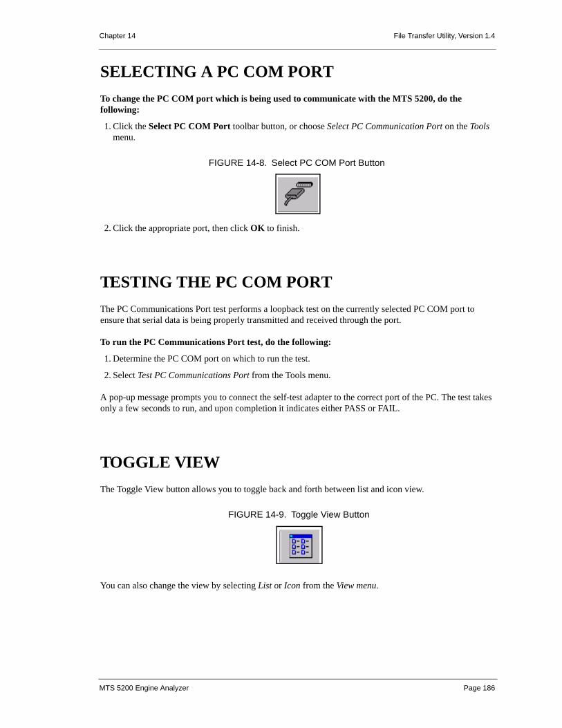
Chapter 14 File Transfer Utility, Version 1.4
SELECTING A PC COM PORTTo change the PC COM port which is being used to communicate with the MTS 5200, do the following:
1. Click the Select PC COM Port toolbar button, or choose Select PC Communication Port on the Tools menu.
2. Click the appropriate port, then click OK to finish.
TESTING THE PC COM PORTThe PC Communications Port test performs a loopback test on the currently selected PC COM port to ensure that serial data is being properly transmitted and received through the port.
To run the PC Communications Port test, do the following:
1. Determine the PC COM port on which to run the test.
2. Select Test PC Communications Port from the Tools menu.
A pop-up message prompts you to connect the self-test adapter to the correct port of the PC. The test takes only a few seconds to run, and upon completion it indicates either PASS or FAIL.
TOGGLE VIEWThe Toggle View button allows you to toggle back and forth between list and icon view.
You can also change the view by selecting List or Icon from the View menu.
FIGURE 14-8. Select PC COM Port Button
FIGURE 14-9. Toggle View Button
MTS 5200 Engine Analyzer Page 186

Chapter 14 File Transfer Utility, Version 1.4
FILE NAMING CONVENTIONThe File Transfer Utility renames all uploaded files to provide more organized file management and to ensure that all files have a unique file name. The following illustrates the format of the file names.
FTU File Name FormatOperating Mode Descriptions:
SCP 4-Channel Oscilloscope
IGN Ignition Mode
VAC Vacuum Waveform Mode
GMM Graphing Multi-meter
FCI Failed Cylinder ID Test
CBT Cylinder Balance Test
CKK Cranking kV Test
MTS 5200 Engine Analyzer Page 187

A. MTS 5200 WARRANTY
The MTS 5200 Engine Analyzer is warranted by Vetronix Corporation to be free of defects in material and workmanship for a period of 2 years from the date of shipment to the original consumer. The cables and accessories for the MTS 5200 Engine Analyzer are warranted by Vetronix Corporation to be free of defects in material and workmanship for a period of 1 years from the data of shipment to the original consumer. If a product is found to be defective during this period the product can be returned to a Vetronix Corporation Service center and the unit will be repaired or replaced free of charge. This warranty does not cover any part that has been abused, or used in a manner inconsistent with instructions regarding its use, including, but not limited to, the following:
• Damage due to improper product operation or product modification.
• Damage due to neglect or lack of proper maintenance as specified in the Operator’s Manual.
• Damage due to use of non-Vetronix supplied cables and accessory items, or unauthorized peripheral equipment.
• Damage due to dropping or other severe impact to the product.
• Damage due to reverse polarity of vehicle power and ground.
• Damage or loss due to unnatural or natural disasters including earthquakes, fire, storms, flood, and lightning.
• Damage due to exposure to excessive low or high temperatures.
• Damage or loss that may occur during shipping.
MTS 5200 Engine Analyzer Page 188

B. SERVICE AND REPAIRINSTRUCTIONS
If you suspect there is a problem with the MTS 5200, follow the Self-Test procedures as described in this manual (see “Self Tests” on page 177). If it is determined that a problem exists, call Vetronix Technical Assistance at 1-800-321-4889 to validate the problem.
If the MTS 5200 requires repair, package the analyzer along with a brief description of the problem, your telephone number, and return address. If necessary, include associated cables, hardware, software, adapters, or tester to allow duplication of the problem at the Service Center.
Send the Engine Analyzer freight pre-paid to the appropriate Vetronix Service Center listed in the following chart. C.O.D.s will not be accepted.
When the product is received at the Service Center, it will be diagnosed, repaired or replaced, and shipped back to you within 48 hours from the time of receipt. If the unit and the defect are covered by the Product
VETRONIX SERVICE CENTERS
U.S., Latin and South America CanadaVetronix Distribution Service Center 2030 Alameda Padre SerraSanta Barbara, CA USA 93103Telephone: (805) 966-2000 or (800) 321-4889
Vetronix Service Center, Ontario c/o Custone Electromotive Inc.1150 Champlain CourtWhitby, Ontario, Canada L1N 6K9Telephone: (905) 668-2664http://www.custone.com
Europe, Africa Asia, OceaniaVetronix Service Center c/o Getronics Service GmbHPhilipp-Reis-Str.1563128 DietzenbachGermanyTelephone: +49 (0) 6074-84280Fax: +49 (0) 6074-84282
Vetronix Service Center c/o Vetronix Japan Co. Ltd.1F KT Excel Building2-36-1 Ikebukuro, Toshima-kuTokyo 171-0014 JAPANTelephone: 492-47-6481
MTS 5200 Engine Analyzer Page 189

Appendix B Service and Repair Instructions
Warranty, there will be no repair charge, and the unit will be returned freight pre-paid by Vetronix via second day air.
If the unit or defect is not covered by the Product Warranty, you will be charged a service fee. In this case you will be informed of the amount, and the repaired unit will be returned C.O.D. for that amount plus the cost of return freight.
MTS 5200 Engine Analyzer Page 190

C. SPECIFICATIONS
Operating Modes Stand-Alone Slave to a host computer
Size and Weight Approximately 10.25" (w) x 9.75" (h) x 2.00" (t)Approximately 4 lbs.
Display Full VGA (640x480) LCD; active area 162.2mm(h) x 121.7mm(v)TFT Color
User Inputs Linear Resistive Touchscreen 11 Fixed Keys with international Labels
Internal Memory Flash EEPROM: 16 MBytes RAM: 32 MBytes
Memory Expansion Type 2 PCMCIA Card
Measurement Inputs
4 Oscilloscope Inputs; ±200 Volts; 1MΩ or 10 MΩAC or DC coupling2 Secondary Ignition Inputs1 Primary Ignition Input: +600/–100 Volts2 Vacuum/Pressure Inputs (Powered Sensors)DVOM + and - Inputs1 RPM Trigger Input (inductive probe)
Hardware Expansion
Expansion Port (26 pin connector) provides support for future H/W growth
Host Interfaces Ethernet interface (10 Mbps)
Other Interfaces Two RS232 Ports (up to 115.2 Kbps)
Power Sources Internal Nickel-Metal-Hydride Battery Pack (isolated) 12V from Vehicle Battery External AC/DC Converter
Glitch Capture Utilized in Oscilloscope, Graphing Multimeter, and Ignition Analyzer Peak Detect
MTS 5200 Engine Analyzer Page 191

Appendix C Specifications
Peak Detect 6 MHz.
Measurement Channels
4 Independent High Speed A/Ds2 Timing Channels used for Frequency, Pulse Width, Duty Cycle & RPM1 DVOM Channel used for DC and AC Voltage, Resistance
Maximum Continuous Sample Rate
1 Msamples / sec (2 channels)
Peak Detect Sample Rate
6 Msamples / sec (2 channels)
MTS 5200 Engine Analyzer Page 192

D. VEHICLES WITH ELECTRONICIGNITION (DIS)
In the following tables, the Figure Number listed in the last column refers to the cylinder configuration figures beginning on page 200.
AUDI
CHRYSLER
Model Year Engine Configuration Engine Code Ignition Type Firing Order Figure
Number1992-95 2.8L V6 AAH EI 1-4-3-6-2-5 81995-99 2.8L V6 AFC EI 1-4-3-6-2-5 81996-97 2.8L V6 ACK EI 1-4-3-6-2-5 81998 2.8L V6 AFC EI (Dual Plug) 1-4-3-6-2-5 81998 2.8L V6 AHA EI (Dual Plug) 1-4-3-6-2-5 82000 2.8L V6 AFC EI 1-4-3-6-2-5 82001 2.8L V6 AHA EI 1-4-3-6-2-5 8
Model Year Engine Configuration Engine Code Ignition Type Firing Order Figure
Number1987-88 1.6L I4 F EI 1-3-4-2 11989-90 1.6L I4 Y EI 1-3-4-2 11989 1.6L I4 Z EI 1-3-4-2 11990-92 2.0L I4 R EI 1-3-4-2 11990-92 2.0L I4 U EI 1-3-4-2 11990-00 3.3L V6 R EI 1-2-3-4-5-6 41991-93 2.2L I4 A EI 1-3-4-2 21991-92 3.0L V6 B EI 1-2-3-4-5-6 191991-92 3.0L V6 C EI 1-2-3-4-5-6 191991-92 3.0L V6 U EI 1-6-3-5-2-4 211991-97 3.8L V6 L EI 1-2-3-4-5-6 41992-00 8.0L V10 E EI 1-10-9-4-3-6-5-8-7-2 221993-94 2.0L I4 E EI 1-3-4-2 11993-98 2.0L I4 F EI 1-3-4-2 11993 3.0L V6 J EI 1-2-3-4-5-6 191993-96 3.0L V6 K EI 1-2-3-4-5-6 191993-94 3.3L V6 T EI 1-2-3-4-5-6 7
MTS 5200 Engine Analyzer Page 193

Appendix D Vehicles with Electronic Ignition (DIS)
FORD
1993-97 3.5L V6 F EI 1-2-3-4-5-6 71994-96 3.0L V6 J EI 1-2-3-4-5-6 191994-97 3.3L V6 J EI 1-2-3-4-5-6 41994-97 3.3L V6 U EI 1-2-3-4-5-6 41994-00 8.0L V10 W EI 1-10-9-4-3-6-5-8-7-2 221995-00 2.0L I4 C EI 1-3-4-2 21995-00 2.0L I4 Y EI 1-3-4-2 21995-00 2.4L I4 X EI 1-3-4-2 21995-97 3.3L V6 T EI 1-2-3-4-5-6 71996 2.0L I4 N EI 1-3-4-2 21996-00 2.4L I4 B EI 1-3-4-2 21996-99 2.4L I4 S EI 1-3-4-2 21996-00 3.8L V6 L EI 1-2-3-4-5-6 41997 2.0L I4 B EI 1-3-4-2 21999-00 3.3L V6 G EI 1-2-3-4-5-6 42000 4.0L I6 S EI 1-5-3-6-2-4 10
Model Year Engine Configuration Engine Code Ignition Type Firing Order Figure
Number1996-98 3.0L V6 1 EI 1-4-2-5-3-6 61998 3.0L V6 1 EI 1-2-3-4-5-6 41997-98 4.2L V6 2 EI 1-4-2-5-3-6 61998-00 3.0L V6 2 EI 1-4-2-5-3-6 61999-00 4.2L V6 2 EI 1-4-2-5-3-6 81995-00 2.0L I4 3 EI 1-3-4-2 21995-00 3.8L V6 4 EI 1-4-2-5-3-6 61996-00 3.8L V6 4 EI 1-4-2-5-3-6 81997-99 4.6L V8 6 EI 1-3-7-2-6-5-4-8 91996-98 4.6L V8 9 EI 1-3-7-2-6-5-4-8 91989-97 2.3L I4 A EI (Dual Plug) 1-3-4-2 31989-92 3.8L V6 C EI 1-4-2-5-3-6 81998-00 2.5L I4 C EI (Dual Plug) 1-3-4-2 31997-00 4.0L V6 E EI 1-4-2-5-3-6 81996 7.5L V8 G EI 1-3-7-2-6-5-4-8 91999-00 2.5L V6 G EI 1-4-2-5-3-6 61996 5.8L V8 H EI 1-3-7-2-6-5-4-8 91991-96 1.9L I4 J EI 1-3-4-2 21995-00 2.5L V6 L EI 1-4-2-5-3-6 61991-93 2.3L I4 M EI (Dual Plug) 1-3-4-2 31996 5.0L V8 N EI 1-3-7-2-6-5-4-8 91997 3.0L V6 N EI 1-4-2-5-3-6 61993-95 3.2L V6 P EI 1-4-2-5-3-6 61996-00 5.0L V8 P EI 1-3-7-2-6-5-4-8 91997-00 2.0L I4 P EI 1-3-4-2 21989-95 3.8L V6 R EI 1-4-2-5-3-6 81996-99 3.0L V6 S EI 1-4-2-5-3-6 61996-00 3.0L V6 U EI 1-4-2-5-3-6 61996-00 3.0L V6 U EI 1-4-2-5-3-6 81993-98 4.6L V8 V EI 1-3-7-2-6-5-4-8 91995-98 4.6L V8 V EI 1-3-7-2-6-5-4-8 201998-00 3.0L V6 V EI 1-4-2-5-3-6 61991-99 4.6L V8 W EI 1-3-7-2-6-5-4-8 91993-97 3.0L V6 W EI 1-2-3-4-5-6 41990-00 4.0L V6 X EI 1-4-2-5-3-6 81997-98 4.6L V8 X EI 1-3-7-2-6-5-4-8 91989-95 3.0L V6 Y EI 1-4-2-5-3-6 61997-99 2.0L I4 Z EI 1-3-4-2 2
Model Year Engine Configuration Engine Code Ignition Type Firing Order Figure
Number
MTS 5200 Engine Analyzer Page 194

Appendix D Vehicles with Electronic Ignition (DIS)
GENERAL MOTORS
HONDA
Model Year Engine Configuration Engine Code Ignition Type Firing Order Figure
Number1987-89 2.0L I4 1 EI 1-3-4-2 21992-00 3.8L V6 1 EI 1-6-5-4-3-2 131999-00 1.3L I4 2 EI 1-3-4-2 21987-88 3.8L V6 3 EI 1-6-5-4-3-2 131992-94 2.3L I4 3 EI-QUAD4 1-3-4-2 21992-00 2.2L I4 4 EI 1-3-4-2 21994-00 2.2L I4 4 EI 1-3-4-2 31999-00 1.6L I4 6 EI (Hybrid) 1-3-4-2 31987-89 3.8L V6 7 EI 1-6-5-4-3-2 141991-00 1.9L I4 7 EI 1-3-4-2 21995-00 1.9L I4 8 EI 1-3-4-2 21999-00 1.8L I4 8 EI 1-3-4-2 21991-94 1.9L I4 9 EI 1-3-4-2 21993-99 4.6L V8 9 EI 1-2-7-3-4-5-6-8 161989-94 2.3L I4 A EI QUAD4 1-3-4-2 21988-91 3.8L V6 C EI 1-6-5-4-3-2 131995-00 4.0L V8 C EI 1-2-7-3-4-5-6-8 161987-95 2.3L I4 D EI QUAD4 1-3-4-2 21996-00 3.4L V6 E EI 1-2-3-4-5-6 41990-91 2.2L I4 G EI 1-3-4-2 21992 2.0L I4 H EI 1-3-4-2 21993-94 2.0L I4 H EI 1-3-4-2 21989-95 5.7L V8 J EI 1-8-4-3-6-5-7-2 121999-00 3.1L V6 J EI 1-2-3-4-5-6 41995-00 3.8L V6 K EI 1-6-5-4-3-2 131996-00 3.8L V6 K EI 1-6-5-4-3-2 141987-95 3.0L V6 L EI 1-6-5-4-3-2 131993-00 3.1L V6 M EI 1-2-3-4-5-6 41989-93 3.3L V6 N EI 1-6-5-4-3-2 131987-92 2.5L I4 R EI 1-3-4-2 21999-00 3.0L V6 R EI 1-2-3-4-5-6 71993 3.4L V6 S EI 1-2-3-4-5-6 71994-95 3.4L V6 S EI 1-2-3-4-5-6 71988-94 3.1L V6 T EI 1-2-3-4-5-6 41996-00 2.4L I4 T EI QUAD4 1-3-4-2 21987-91 2.5L I4 U EI 1-3-4-2 21989-90 3.1L V6 V EI 1-2-3-4-5-6 71987-89 2.8L V6 W EI 1-2-3-4-5-6 41993 3.1L V6 W EI 1-2-3-4-5-6 41991-97 3.4L V6 X EI 1-2-3-4-5-6 41993-99 4.6L V8 Y EI 1-2-7-3-4-5-6-8 16
Model Year Engine Configuration Engine Code Ignition Type Firing Order Figure
Number1994-95 3.2L V6 6VD1 EI 1-2-3-4-5-6 61998 2.2L I4 X22SE EI 1-3-4-2 1
MTS 5200 Engine Analyzer Page 195

Appendix D Vehicles with Electronic Ignition (DIS)
HYUNDAI
ISUZU
KIA
LAND ROVER
LEXUS
Model Year Engine Configuration Engine Code Ignition Type Firing Order Figure
Number1992-95 1.6L I4 R EI 1-3-4-2 21992-98 1.8L I4 M EI 1-3-4-2 21992-99 2.0L I4 F EI 1-3-4-2 21995 1.5L I4 J EI 1-3-4-2 11995-98 1.5L I4 K EI (Hybrid) 1-3-4-2 21995 1.5L I4 N EI 1-3-4-2 21999 1.5L I4 N EI 1-3-4-2 21999 2.4L I4 D EI (Hybrid) 1-3-4-2 21999 2.5L V6 E EI 1-2-3-4-5-6 4
Model Year Engine Configuration Engine Code Ignition Type Firing Order Figure
Number1991-92 1.6L I4 4XE1-WT EI 1-3-4-2 21992-96 3.2L V6 6VD1 EI 1-2-3-4-5-6 71999 2.2L I4 X22SE EI 1-3-4-2 3
Model Year Engine Configuration Engine Code Ignition Type Firing Order Figure
Number1995 2.0L I4 1 EI 1-3-4-2 31995-99 2.0L I4 3 EI (Hybrid) 1-3-4-2 31999 1.8L I4 5 EI (Hybrid) 1-3-4-2 2
Model Year Engine Configuration Engine Code Ignition Type Firing Order Figure
Number1995-99 4.0L V8 2 EI 1-8-4-3-6-5-7-2 121996-99 4.6L V8 4 EI 1-8-4-3-6-5-7-2 12
Model Year Engine Configuration Engine Code Ignition Type Firing Order Figure
Number1996-99 3.0L V6 1MZ-FE EI (Hybrid) 1-2-3-4-5-6 41999 3.0L I6 2JZ-GE EI (Hybrid) 1-5-3-6-2-4 10
MTS 5200 Engine Analyzer Page 196

Appendix D Vehicles with Electronic Ignition (DIS)
MAZDA (8TH VIN POSITION)
MAZDA (ENGINE CODE)
MERCEDES BENZ
Model Year Engine Configuration Engine Code Ignition Type Firing Order Figure
Number1991-99 4.0L V6 X EI 1-4-2-5-3-6 81994-97 2.3L I4 A EI (Dual Plug) 1-3-4-2 31995-99 3.0L V6 U EI 1-4-2-5-3-6 81998 2.5L I4 A (Dual Plug) 1-3-4-2 31999 2.5L I4 C EI 1-3-4-2 3
Model Year Engine Configuration Engine Code Ignition Type Firing Order Figure Number
1987-94 1.3L R RE-13B EI 1-21990-93 1.6L I4 B6 EI 1-3-4-2 31994-99 1.8L I4 BP EI 1-3-4-2 31995 1.3L R 13B-Turbo EI 1-21998-99 2.0L I4 FS EI 1-3-4-2 21998-99 2.5L V6 KL EI 1-2-3-4-5-6 41999 1.6L I4 ZM EI (Hybrid) 1-3-4-2 2
Model Year Engine Configuration Engine Code Ignition Type Firing Order Figure
Number1993 2.8L I6 104.942 EI (Hybrid) 1-5-3-6-2-4 101993-95 3.2L I6 104.992 EI (Hybrid) 1-5-3-6-2-4 101994-95 2.2L I4 111.961 EI (Hybrid) 1-3-4-2 21994-97 2.8L I6 104.941 EI (Hybrid) 1-5-3-6-2-4 101994-97 3.2L I6 104.991 EI (Hybrid) 1-5-3-6-2-4 101994-99 3.2L I6 104.994 EI (Hybrid) 1-5-3-6-2-4 101995-97 3.6L I6 104.941 EI (Hybrid) 1-5-3-6-2-4 101996 2.2L I4 111.961 EI (Hybrid) 1-3-4-2 21996-97 3.2L I6 104.995 EI (Hybrid) 1-5-3-6-2-4 101997-99 2.3L I4 111.973 EI (Hybrid) 1-3-4-2 21997-98 2.3L I4 111.974 EI (Hybrid) 1-3-4-2 21998 3.0L I6 104 EI (Hybrid) 1-5-3-6-2-4 101998 3.2L V6 112.942 EI (Hybrid) 1-4-3-6-2-5 71999 2.3L I4 111.975 EI (Hybrid) 1-3-4-2 31999 6.0L V12 120.983 EI (Hybrid) 1-12-5-8-3-10-6-7-2-11-4-9 27
MTS 5200 Engine Analyzer Page 197

Appendix D Vehicles with Electronic Ignition (DIS)
MITSUBISHI
SUBARU
SUZUKI
TOYOTA
Model Year Engine Configuration Engine Code Ignition Type Firing Order Figure
Number1989-92 1.6L I4 Y EI 1-3-4-2 11989 1.6L I4 Z EI 1-3-4-2 11989-92 2.0L I4 R EI 1-3-4-2 11990-92 2.0L I4 U EI 1-3-4-2 11991-92 3.0L V6 B EI 1-2-3-4-5-6 191991-92 3.0L V6 C EI 1-2-3-4-5-6 191993-94 2.0L I4 E EI 1-3-4-2 11993-99 2.0L I4 F EI 1-3-4-2 11993-99 3.0L V6 J EI 1-2-3-4-5-6 191993-99 3.0L V6 K EI 1-2-3-4-5-6 191994 2.4L I4 L EI 1-3-4-2 11994-97 3.5L V6 M EI 1-2-3-4-5-6 71995-99 2.0L I4 Y EI 1-3-4-2 21995-99 2.4L I4 G EI 1-3-4-2 11997-99 1.8L I4 C EI (Hybrid) 1-3-4-2 11997-98 3.0L V6 P EI 1-2-3-4-5-6 71999 2.4L I4 G EI (Hybrid) 1-3-4-2 21999 3.0L V6 H EI 1-2-3-4-5-6 71999 3.5L V6 R EI 1-2-3-4-5-6 7
Model Year Engine Configuration Engine Code Ignition Type Firing Order Figure
Number1990-95 2.2L H4 6 EI 1-3-2-4 241993-97 1.8L H4 2 EI 1-3-2-4 241995-96 1.8L H4 1 EI 1-3-2-4 241996-98 2.2L H4 3 EI 1-3-2-4 241996-99 2.2L H4 4 EI 1-3-2-4 241996-99 2.5L H4 6 EI 1-3-2-4 24
Model Year Engine Configuration Engine Code Ignition Type Firing Order Figure
Number1999 1.3L I4 2 EI (Hybrid) 1-3-4-2 21999 1.6L I4 3 EI (Hybrid) 1-3-4-2 21999 1.6L I4 O EI (Hybrid) 1-3-4-2 3
Model Year Engine Configuration Engine Code Ignition Type Firing Order Figure
Number1987-92 3.0L I6 7M-GTE EI 1-5-3-6-2-4 101995-98 1.5L I4 5E-FE EI (Hybrid) 1-3-4-2 21995-99 3.4L V6 5VZ-FE EI (Hybrid) 1-2-3-4-5-6 71996-99 3.0L V6 1MZ-FE EI (Hybrid) 1-2-3-4-5-6 41997-99 2.2L I4 5S-FE EI (Hybrid) 1-3-4-2 21997-99 2.7L I4 3RZ-FE EI 1-3-4-2 31998-99 1.8L I4 1ZZ-FE EI 1-3-4-2 21998-99 2.0L I4 3S-FE EI 1-3-4-2 31998-99 2.4L I4 2RZ-FE EI 1-3-4-2 31998 3.0L I6 2JZ-GE EI (Hybrid) 1-5-3-6-2-4 101998 3.0L V6 1MZ-FE EI (Hybrid) 1-2-3-4-5-6 7
MTS 5200 Engine Analyzer Page 198

Appendix D Vehicles with Electronic Ignition (DIS)
VOLKSWAGEN (ENGINE CODE)
VOLKSWAGEN (5TH VIN POSITION)
VOLVO
Model Year Engine Configuration Engine Code Ignition Type Firing Order Figure
Number1993-99 2.8L V6 AAA EI 1-5-3-6-2-4 41997-99 2.8L V6 AES EI 1-5-3-6-2-4 41999-00 2.0L I4 AEG EI 1-3-4-2 21999-00 2.8L V6 AFP EI 1-5-3-6-2-4 41999 2.8L V6 AHA EI 1-4-3-6-2-5 42000 2.8L V6 ATQ EI 1-4-3-6-2-5 4
Model Year Engine Configuration Engine Code Ignition Type Firing Order Figure
Number2000 2.8L V6 H EI 1-5-3-6-2-4 4
Model Year Engine Configuration Engine Code Ignition Type Firing Order Figure
Number1999-00 2.0L I4 25 EI 1-3-4-2 2
MTS 5200 Engine Analyzer Page 199

Appendix D Vehicles with Electronic Ignition (DIS)
Cylinder Configurations
Cylinder ConfigurationFig#Cylinder ConfigurationFig
#
1
2
3
4
6
7
8
9
10
12
MTS 5200 Engine Analyzer Page 200

Appendix D Vehicles with Electronic Ignition (DIS)
Cylinder ConfigurationFig# Cylinder ConfigurationFig
#
13
14
16
19
20
21
22
24
27
MTS 5200 Engine Analyzer Page 201

E. OSCILLOSCOPE COMPONENTCATEGORIES
Within each of these components in 4-Channel Oscilloscope mode you can choose specific categories to test. Table E-1, “Oscilloscope Component Categories” lists the categories that can be accessed through each oscilloscope component.
COMPONENT SELECTION CATEGORIES
Actuators Idle Air Control (IAC)Idle Speed Control (ISC)EGR Control (EGRC)Canister Purge (CANP)AIR Diverter (TAD)AIR Bypass (TAB)Shift Solenoid (SS)
Current Waveforms Fuel PumpPrimary IgnitionHigh Current ProbeLow Current Probe
Distributor Hall Effect P/UMagnetic P/USpark TimingOptical P/U
Electrical Alternator RippleBattery VoltageGrounds
Fuel Injectors Negative Control (Common)Peak ‘n Hold
Table E-1: Oscilloscope Component Categories
MTS 5200 Engine Analyzer Page 202

Appendix E Oscilloscope Component Categories
Ignition PrimarySecondarySync ProbeSecondary/SyncPrimary/Sync
Sensors TPSECTMAP (Analog)MAP (Digital)Crank Position (CKP) (Hall Effect)CKP (Magnetic)Knock Sensor (KS)EGR Valve Position (EVP)Vehicle Speed (VSS) AnalogVSS (Digital)O2SIATMAF (Analog)MAF (Digital) High FrequencyMAF (Digital) Low FrequencyCam Position (CMP) (Hall Effect)CMP (Magnetic)BARO (Analog)BARO (Digital)Wheel Speed (WSS)
Vacuum/Pressure AC VacuumDC VacuumAC/DC Vacuum/SyncAC Vacuum/SyncPressurePressure/Sync
COMPONENT SELECTION CATEGORIES
Table E-1: Oscilloscope Component Categories
MTS 5200 Engine Analyzer Page 203

F. GLOSSARY
TERM DEFINITION
Air Core A type of construction of a transformer or coil in which air, instead of magnetic material, fills the space between conductors.
Alternating An electric current that is constantly changing polarity from positive to negative and back again.
Ammeter A meter used to measure electrical current within a circuit in amperes.
Amperage The amount of current flow through a conductor.
Ampere The unit for measuring the rate of electric current.
Analog Signal A voltage signal or processing action that varies continuously with the variable being measured or controlled.
Analog-to-Digital Circuitry used to convert analog information into numeric form for use in a digital computer.
Armature The rotating part of a generator or motor.
BNC British Naval Connector.
C3I-Computer Controlled Coil Ignition
(Used on 3.0L, 3.8L, 3.8L turbo, 3300 and 3800 engines). Produces the ignition spark without the aid of an ignition distributor. Now called Electronic Ignition (EI).
Camshaft Position (CMP) Sensor
A device that measures the rotational speed of the camshaft and transmits this information to the Powertrain Control Module (PCM).
Capacitance The ability of two conducting surfaces, separated by an insulator, to store an electric charge.
Capacitor A device that stores voltage without affecting the voltage in any way. Also called condenser.
Cathode-Ray Tube A tube in which the electrons can be focused in a small spot on a fluorescent screen at the opposite end of the structure. By varying the position of the spot a picture or pattern can be produced on the screen. A television picture tube or oscilloscope display tube.
CCFL Backlighting Cold Cathode Florescent Lighting.
Condenser See Capacitor.
Conductance A measure of the ease with which a conductor allows electron flow. In DC circuits, it is the reciprocal of resistance.
MTS 5200 Engine Analyzer Page 204

Appendix F Glossary
Conduction The transmission of heat or electricity through, or by means of, a conductor.
Conductor Usually, a wire or other metallic object made up of atoms whose free electrons are easily dislodged allowing easy electron flow from atom to atom.
Continuity A continuous path for the flow of an electrical current.
Conventional Theory The flow of current in an electrical circuit in which direction is from positive to negative.
CNP Coil near Plug.
COP Coil on Plug.
CPC Circular Plastic Connector.
CPS Cycles per Second. Replaced by the term Hertz (Hz).
Crankshaft Position (CKP) Sensor
A device that measures and inputs crankshaft rotational speed information to the PCM. This is the primary input for most control systems, and the PCM prevents ignition and fuel delivery unless this signal is present.
DI Distributor Ignition.
Digital Signal An electrical signal that is either ON or OFF, High or Low, or 1 or 0. Only two states of logic are detected.
Digital-to-Analog (DA) Converter
Circuitry used to change digital voltage signals into analog voltage signals.
DIMM Dual In-Line Memory Module; standard PC Memory.
Direct Current (DC) An electrical current which flows in one direction only.
DIS • Direct Ignition System. Produces the ignition spark without the aid of an ignition distributor. Now called Electronic Ignition (EI) System.
• Distributorless Ignition System. A generic description for any ignition system that produces ignition spark without the aid of an ignition distributor. Now called Electronic Ignition System.
DSO Digital Storage Oscilloscope.
DVOM (10 Meg.) Digital volt-ohmmeter with a minimum of 10 million ohms resistance. Allows measurement of values in a circuit without affecting circuit operation.
Duty Cycle The relative amount of circuit on time (usually expressed in percent).
Dwell The amount of time (recorded on a dwell meter in degrees) that current passes through a closed switch; for example, ignition contact points or internal switches in an electronic control module.
ECM Engine Control Module. A microprocessor-based device which contains electronic circuitry to control and monitor air/fuel and emission systems, and aid in diagnostics. Also see PCM.
EEPROM Electrically Erasable Programmable Read Only Memory.
EI Electronic Ignition. A generic term used to describe any ignition system that produces spark without a distributor, formerly called DIS.
Electromagnetic A soft iron core wrapped in a coil of a current-carrying conductor. Current in the conductor induces a magnetic force around the core.
Electromagnetic Induction
The creation of voltage within a conductor when relative motion exists between the conductor and a magnetic field.
EMI Electromagnetic Interference or Noise. An unwanted signal interfering with another needed signal (like an electric razor upsetting a television picture or high-voltage power lines upsetting the AM radio in a car).
EST Electronic Spark Timing. ECM- or PCM-controlled timing of ignition spark. Now called Ignition Control (IC).
TERM DEFINITION
MTS 5200 Engine Analyzer Page 205

Appendix F Glossary
Ethernet Card Standard PC hardware PC to PC communications.
Farad The unit of measurement for capacitance. One farad is the capacitor value in which a charge of one coulomb produces a change of one volt in the potential difference between its terminals. The farad is too large a value for practical use. The microfarad (1 millionth of a farad) and the picofarad (1 millionth of a microfarad) are used in practical applications.
Ferrous A metal which responds to the influence of a magnetic field.
Frequency The number of cycles of a periodic phenomenon in a given unit of time, usually per second.
Ground A reference point from which voltage measurements may be made. Also, a return path or current flow to the source.
Hall-Effect Switch A signal-generating switch that develops a transverse voltage across a current-carrying semiconductor when subjected to a magnetic field.
HEI High Energy Ignition. A Delco Remy ignition distributor that uses an electronic module and pickup coil in place of contact points and is capable of producing secondary output of 40,000 volts. Now called Distributor Ignition (DI).
Henry The unit of measurement for inductance. One henry of inductance is present in a closed circuit when a current variation of one ampere per second includes one volt.
Hertz Cycle per second. Abbreviated Hz.
High A voltage greater than ground or zero, like the output wire of an oxygen sensor is called 02 high, as compared to the ground, which is called 02 low. In digital signals, high is ON and low is OFF.
High-Impedance Voltmeter
Has high opposition to the flow of electrical current. Good for reading circuits with low current flow, such as those found in electronic systems.
IC Ignition Control.
ICB Intrusive Cylinder Balance
IDI Integrated Direct Ignition. (Used on 2.3L Quad 4 engine.) Produces the ignition spark without the aid of an ignition distributor. Now called Electronic Ignition (EI) system.
Ignition Coil In a gasoline engine electrical system, an iron core transformer used to convert a low voltage DC into the high voltage required to produce the ignition spark.
Impedance The total opposition a circuit offers to the flow of alternating current. It includes resistance and reactance and is measured in ohms.
Induced Produced by the influence of a magnetic or electrical field.
Induced Current The current generated in a conductor as it moves through a magnetic field, or as a magnetic field is moved across a conductor.
Induced Voltage The voltage produced as a result of an induced current flow.
Inductance That property of a coil or other electrical device that opposes any change in the existing current. It is present only when an alternating or pulsing current is flowing and has no effect on the flow of the DC, or static, current.
Induction The act or process by which an electrical conductor becomes electrified when near a charged body; in a transformer, the increase or decrease in voltage output of the secondary when the field in the primary collapses.
Integrated Circuit An electronic circuit containing many interconnected amplifying devices and elements formed on a single body, or chip, of semiconductor material.
Ionization The state of an insulator which allows the passage of current due to the presence of charged particles.
Kilo A prefix meaning 1,000.
Kilohertz One thousand cycles per second. Abbreviated kHz.
TERM DEFINITION
MTS 5200 Engine Analyzer Page 206

Appendix F Glossary
Kilovolt One thousand volts. Abbreviated kv.
LCD Liquid Crystal Display. An indicator consisting of a sandwich of glass containing electrodes and polarized fluid. Voltage applied to the fluid allows light to pass through it.
LED Light Emitting Diode. A gallium-arsenide diode that emits energy as light.
Logic Gates Circuit switching functions within a computer that acts as routes for output voltage signals according to differing combinations of input signals.
Magnet Any body with the property of attracting iron and steel. Temporary magnets are made by surrounding a soft-iron core with a strong electromagnetic field. Permanent magnets are made with steel.
Magnetic Field The field produced by a magnet or a magnetic influence. It has force and direction.
Magnetic Flux The invisible, directional lines of force which make up a magnetic field.
Magnetic Pulse Generator
A signal-generating device that creates a voltage pulse as magnetic flux changes around a pickup coil.
Magnetism A property possessed by certain materials by which these materials can exert mechanical force on neighboring masses of magnetic materials.
Millisecond (ms) One one-thousandth of a second.
Misfire Failure of the air-fuel mixture to ignite during the power stroke.
Multimeter A test instrument with suitable switching facilities to measure voltage, current, and resistance. Also called a volt-ohm-milliammeter.
Mutual Induction Creation of voltage in one conductor by the rise and collapse of the magnetic field surrounding another conductor.
NiMH Battery Nickel Metal Hydride Battery.
Optical Sensor An electronic device that uses an LED and phototransistor to generate a voltage signal.
Oscillating Moving back and forth with a steady rhythm.
PCM Powertrain Control Module
PCMCIA Card Personal Computer Memory Card Industry Association.
Photoconductive Cell A light-sensitive resistor that changes its resistance in proportion to the amount of light striking its sensitive surface. Two types of cells are available: the cadmium sulfide cell and the cadmium selenide cell. The cadmium sulfide cell is sensitive to visible light; the Cadmium selenide cell is faster and sensitive to infrared light.
Photoconductor A material whose resistance varies with the application of light.
Photodiode A semiconductor diode in which the reverse current decreases whenever the unit is illuminated.
Photoelectric Cell A light-sensitive cell that translates variations in light into corresponding variations in electrical signals.
Photoresistor A light-sensitive semiconductor resistor whose resistance decreases when the unit is subjected to light.
Photosensitive A devise capable of emitting electrons when struck by light.
Phototransistor A light sensitive device of moderately high sensitivity and relatively high speed. The response is a function of light intensity.
Pickup Coil An inductive coil that generates a voltage pulse as the teeth of a rotating trigger wheel create magnetic flux changes.
Polarity Having two opposite charges—one positive and one negative.
RFI Radio Frequency Interference. A form of electromagnetic interference created in the ignition secondary circuit which is strong enough to disrupt radio and television transmission.
TERM DEFINITION
MTS 5200 Engine Analyzer Page 207

Appendix F Glossary
RAM Random Access Memory. A computer memory in which the data can be retrieved at a speed that is independent of its location in the memory.
RC Circuit A network containing resistors and capacitors.
RC Constant The time constant of an RC circuit. It is equal (in seconds) to the value of the resistance in ohms multiplied by the capacitance in farads.
Rectified Electrical current changed from alternating (AC) to direct (DC).
Reluctance The tendency of some materials to resist penetration by magnetic flux lines. Magnetic line concentrate in areas of low reluctance and avoid areas of high reluctance.
Reluctor Any device that causes a change in reluctance of a material to pass magnetic lines of force.
Resistance Opposition to electric current flow.
Saturation The state of a coil when current flow has reached the design maximum and the magnetic field has reached its maximum strength.
Secondary The output winding of a transformer; that is, the winding in which current flow is due to inductive coupling with another coil called the primary.
Sine Wave Voltage The constant change, first to a positive peak and then to a negative peak, of an induced, alternating voltage in a conductor.
SPI Serial Peripheral Interface.
Square Wave An essentially square or rectangular shaped wave. A wave that alternately assumes two fixed values for equal lengths of time with a negligible transition time between the two values.
Static Electricity Voltage resulting from the transfer of electrons from the surface of one material to the surface of another material. The electrons are static, or at rest.
Transducer A device that converts one form of energy to another; for example, an optical sensor which converts light into a voltage signal.
Transistor A semiconductor device that can control an electrical current by varying a smaller base current. This device acts like a mechanical relay with a variable resistor at the points.
Trigger If a trigger is set at a specific voltage level, and the signal being sampled achieves that voltage level, then the signal is displayed on the screen.
UART Universal Asynchronous Receive Transmit.
USB Universal Serial Bus; standard high-speed PC communication device, 12 Mega bits/second.
Volt The unit for measuring the amount of electromotive force.
Voltage The electromotive force that moves current through a circuit. The potential difference in electrical force between two points when one is negatively charged and the other is positively charged.
Voltage Drop The measurement of the loss of voltage caused by the resistance of a conductor or a circuit device.
Voltage Potential An electrical pressure that creates an imbalance of electrons between two points and is capable of producing a flow of current if a path or circuit is provided.
Voltmeter A meter used to measure electromotive force in volts.
Winding One or more turns of a wire forming a coil. Also, the individual coils of a transformer.
Zener Diode A junction of semiconductor materials that allows reverse current flow without damage at any voltage above a specific value.
TERM DEFINITION
MTS 5200 Engine Analyzer Page 208

INDEX
Symbols< trigger level indicator marker 34[G] see G marker[P] see P marker[T] see T marker[W] see W marker
Aabort test 130AC coupling 30AC vacuum 25AC voltage 149AC/DC coupling 29adapters 8aliasing 31arm button 34arming the oscilloscope 34arrow buttons 158, 164auto trigger type 34automated cylinder balance test 105auxiliary port
calibration 179
Bbarchart
firing kV 70firing volts 52
battery charge 179bitmap files 163, 182BMP file extensions 163
Ccalibrating vacuum probe 110
calibrationauxiliary port 179touch screen 178vacuum probe 84, 178
CH1 port 139channel
AC/DC coupling 29multiple signals 25offset 28settings 27time/division 31usage 25volts/division 28
channel source 40charge battery 179circuit analysis 138clear DTCs 127coil near plug 14, 17, 61, 94communication port test 177companion cylinders 58 to 59, 71component
example waveform 26selection 24
connections 7contacting Vetronix Corporation 189continue search 168continuity 150cranking kV test setup 101current waveform 25cursor information box 37cursors
active 37inactive 37saving 37
cylindercompanion 59, 71configuration 17 to 18, 200firing order 18help 17quick check 77selection 15, 18, 47, 66
MTS 5200 Engine Analyzer 209

Index
trigger 54cylinder balance test
automated 105, 117manual 105, 113
cylinder tests 124
Ddatabase, test vehicle 14date and time 173DC coupling 29DC low/high current 141DC voltage 141, 149default setup 27, 40deleting files 169detail view 164diagnostic trouble code 77diode check 150DIS 58, 113display mode 47, 66
test results 132distributor ignition (DI)
description 45, 58, 92leads connection 19, 58, 92
download mode 182duty cycle 141, 146DVOM port 148
EECU 121edit notes 165electronic ignition (EI)
description 58leads connection 19
ENA 113engine, test vehicle 16engineering mode 40English/metric units 123example waveform 26
Ffailed cylinder ID test 121falling edge 35file extension
BMP 163RPB 163
file list button 158file naming conventions 163file transfer utility (FTU) 20, 182firing order 18, 193Ford
dual plug distributorless ignition system 62multi-strike ignition system 63
format flash 169, 180free run trigger type 34freeze button 19, 119frequency 141
GG marker 54, 74, 79, 89General Motors integrated direct ignition 64glitch button 36glitch capture 31, 36, 145ground coupling 30ground leads 6, 23ground offset 54, 74, 79, 89
IICB 104ignition demonstration 180ignition mode
barchart 51, 69parade 49, 67power/waste comparison 71raster 50, 68single cylinder 48, 66superimposed 51, 69
ignition settingkV volts/division 72time/division 52, 72, 80volts/division 52, 80
ignition systemscoil near plug 14, 61, 94distributor 58, 92dual plug distributorless 62electronic 58integrated direct ignition 64multi-strike 63NAP-Z 65
ignition type, test vehicle 18intermittent problem analysis 138, 145IP address 174
Jjunction box 59, 92
Kkeypad functions 7
Llast vehicle 19leads
ground 6, 23optional 10spider 59, 92standard 8
leads connectionDI 19dual distributor ignition system 61, 93dual plug distributorless ignition system 63DVOM 148EI 19failed cylinder ID test 122
MTS 5200 Engine Analyzer 210

Index
Ford multi-strike ignition system 64General Motors integrated direct ignition 64graphing multimeter 139intrusive cylinder balance test 106Nissan NAP-Z ignition system 65oscilloscope 23primary ignition
leads 45secondary ignition 61, 93vacuum waveform 82
list view 164live engine RPM 98live firing kV 98
Mmain button 53, 73, 79, 89main menu 14, 155manual cylinder balance test 105manual setup 24manufacturer, test vehicle 15maximum saved files 163measurement range 152mechanical tests 5memory 20metric/English units 123minimum/average/maximum values 146, 151
Nnetwork IP address 174new search 168Nissan NAP-Z ignition system 65normal trigger type 34notations in this manual 1
Ooffset 28open circuit 150operating mode 140oscilloscope
arming 34component selection 24component tests 202display 24input source 40leads 23manual setup 24signal finder 27
PP marker 72pattern display 84pattern spacing 50, 55, 68, 75play button 157playback
menu 157mode 156
portCH1 139com 1 177com 2 177DVOM 148sec ign 77sync 139, 144
ports on 5100 6 to 7post-trigger 154power spark 58power/waste comparison 71precautions 2pressure 142pressure transducer 140pre-trigger 154primary ignition
pattern 45probes 10pulse width
description 141time low/high 146
Rraster display 55recall button 20, 120recall vehicle 125recording indicator 156repair 189reset button 152resistance 150retest button 131retest vehicle 125rising edge 35RPB file extension 163RPM measurement 143run button 19, 120
Ssafety guidelines 2sampling rate, glitch capture 36save 131save button 20, 120, 158saved files, maximum 163saving 100search, file manager 167secondary ignition lead 77, 106secondary ignition system 91secondary probe shield 77select display mode 47, 66selecting vehicle 14self tests 177, 189service 189setup button 73, 79, 88setup functions 53, 73signal finder 27single shot trigger type 34smoothing 87snapshot
continue/cancel 155file extension 163
MTS 5200 Engine Analyzer 211

Index
length 154menu 155warning messages 160
snapshot button 157software version number 176specifications 191spider leads 59, 92start test button 129stop button 157sync orientation 144sync probe 54, 58, 74, 92, 106, 139, 144
TT marker 32, 35, 54, 74, 79technical assistance 189TechView upload 168temperature
Celsius/Fahrenheit 142, 175measurement 142
test results 132test time 128test vehicle selection
database 14entering 14ignition type 18last vehicle 19manual setup 17
time and date 173time/division 31, 52, 80, 145timing failed cylinder test 128toggling
continue and cancel 155ground offset and volts/division 56, 76pattern spacing and volts/division 55, 75pause and resume 157play and stop 157snapshot and bitmap 166trigger and stop 156trigger position and time/division 56, 76
touch screencalibration 177 to 178cleaning 11operation 11test 177
triggercylinder 54, 74, 88edge 35indicator 32level 34point 154position 35, 54, 74, 79, 154positive/negative 145setup 32source 32type
auto 34free run 34normal 34single shot 34
trigger level indicator 34trigger position indicator 35trigger setting box 32
typing notes 166
Uunits of measure 123, 174units/division
auto mode 144vacuum waveform 86
upload button 20uploading files 182utilities menu, file manager 167utilities, analyzer 172
Vvacuum 142vacuum per cylinder display 86vacuum probe 106, 140
calibration 84, 110, 178vacuum waveform 159vacuum waveform display 85vacuum/pressure 25vehicle configuration 15, 19, 124vehicle confirmation 16 to 18vehicle selection 15, 18 to 19vehicles with EI (DIS) 193version number 176view file button 165VIN/Notes 126volts/division 28, 52, 72, 80
WW marker 72warranty 188waste spark 58waveform
distortion 31high frequency 31low frequency 31
MTS 5200 Engine Analyzer 212