Embed Size (px)
Citation preview
8/20/2019 MTS Report to Congress FINAL 73106
http://slidepdf.com/reader/full/mts-report-to-congress-final-73106 1/48
August 2006
A REPORT TO THE UNITED STATES CONGRESS
PURSUANT TO SECTION 1816
OF THE ENERGY POLICY ACT OF 2005
BENEFITS OF USING MOBILE
TRANSFORMERS AND MOBILESUBSTATIONS FOR RAPIDLY
RESTORING ELECTRICAL SERVICE

8/20/2019 MTS Report to Congress FINAL 73106
http://slidepdf.com/reader/full/mts-report-to-congress-final-73106 2/48
8/20/2019 MTS Report to Congress FINAL 73106
http://slidepdf.com/reader/full/mts-report-to-congress-final-73106 3/48
U.S. Department of Energy Mobile Transformer and Substation Report iii
The Secretary [of Energy] shall conduct a study of the benefits of using
mobile transformers and mobile substations to rapidly restore electrical
service to areas subjected to blackouts as a result of —
(A) equipment failure;(B) natural disasters;
(C) acts of terrorism; or
(D) war.
Not later than 1 year after the date of enactment of this Act, the Secretary
shall submit to the President and Congress a report on the study….
— Sec. 1816, the Energy Policy Act of 2005 (enacted August 8, 2005)

8/20/2019 MTS Report to Congress FINAL 73106
http://slidepdf.com/reader/full/mts-report-to-congress-final-73106 4/48
iv U.S. Department of Energy Mobile Transformer and Substation Report
8/20/2019 MTS Report to Congress FINAL 73106
http://slidepdf.com/reader/full/mts-report-to-congress-final-73106 5/48
U.S. Department of Energy Mobile Transformer and Substation Report v
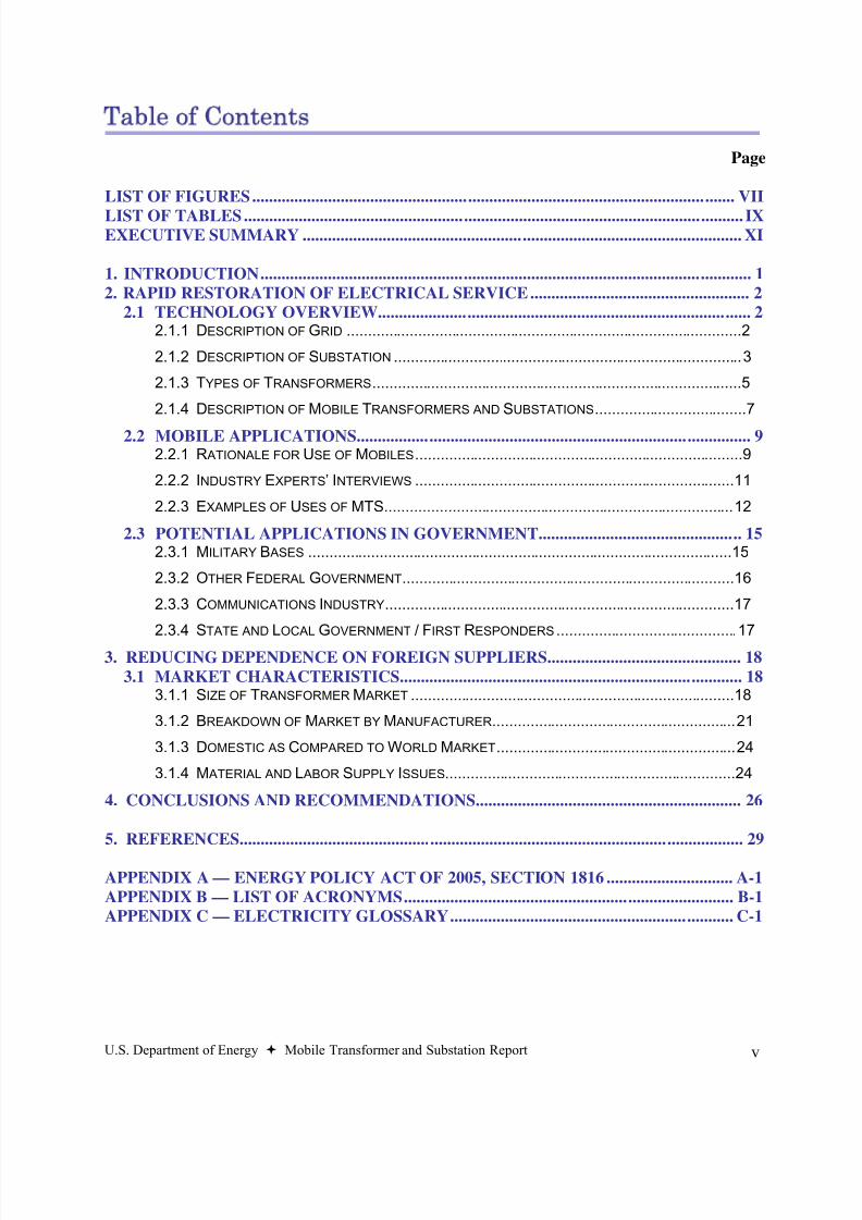
Table of Contents
Page
LIST OF FIGURES.................................................................................................................. VII
LIST OF TABLES...................................................................................................................... IXEXECUTIVE SUMMARY ........................................................................................................ XI
1. INTRODUCTION.................................................................................................................... 1
2. RAPID RESTORATION OF ELECTRICAL SERVICE.................................................... 2
2.1 TECHNOLOGY OVERVIEW........................................................................................ 22.1.1 DESCRIPTION OF GRID ..............................................................................................2
2.1.2 DESCRIPTION OF SUBSTATION ...................................................................................3
2.1.3 TYPES OF TRANSFORMERS........................................................................................5
2.1.4 DESCRIPTION OF MOBILE TRANSFORMERS AND SUBSTATIONS....................................7
2.2 MOBILE APPLICATIONS............................................................................................. 92.2.1 R ATIONALE FOR USE OF MOBILES..............................................................................9
2.2.2 INDUSTRY EXPERTS’ INTERVIEWS ............................................................................11
2.2.3 EXAMPLES OF USES OF MTS...................................................................................12
2.3 POTENTIAL APPLICATIONS IN GOVERNMENT................................................ 152.3.1 MILITARY B ASES .....................................................................................................15
2.3.2 OTHER FEDERAL GOVERNMENT...............................................................................16
2.3.3 COMMUNICATIONS INDUSTRY...................................................................................17
2.3.4 STATE AND LOCAL GOVERNMENT / FIRST RESPONDERS ...........................................17
3. REDUCING DEPENDENCE ON FOREIGN SUPPLIERS.............................................. 18
3.1 MARKET CHARACTERISTICS................................................................................. 183.1.1 SIZE OF TRANSFORMER M ARKET .............................................................................18
3.1.2 BREAKDOWN OF M ARKET BY M ANUFACTURER..........................................................21
3.1.3 DOMESTIC AS COMPARED TO WORLD M ARKET.........................................................24
3.1.4 M ATERIAL AND L ABOR SUPPLY ISSUES.....................................................................24
4. CONCLUSIONS AND RECOMMENDATIONS............................................................... 26
5. REFERENCES....................................................................................................................... 29
APPENDIX A — ENERGY POLICY ACT OF 2005, SECTION 1816 .............................. A-1
APPENDIX B — LIST OF ACRONYMS.............................................................................. B-1
APPENDIX C — ELECTRICITY GLOSSARY................................................................... C-1

8/20/2019 MTS Report to Congress FINAL 73106
http://slidepdf.com/reader/full/mts-report-to-congress-final-73106 6/48
vi U.S. Department of Energy Mobile Transformer and Substation Report
8/20/2019 MTS Report to Congress FINAL 73106
http://slidepdf.com/reader/full/mts-report-to-congress-final-73106 7/48
U.S. Department of Energy Mobile Transformer and Substation Report vii
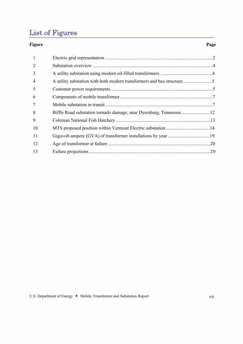
List of Figures
Figure Page
1 Electric grid representation ..........................................................................................22 Substation overview .....................................................................................................4
3 A utility substation using modern oil-filled transformers. ...........................................4
4 A utility substation with both modern transformers and bus structure. .......................5
5 Customer power requirements......................................................................................5
6 Components of mobile transformer..............................................................................7
7 Mobile substation in transit ..........................................................................................7
8 Biffle Road substation tornado damage, near Dyersburg, Tennessee........................12
9 Coleman National Fish Hatchery ...............................................................................13
10 MTS proposed position within Vermont Electric substation .....................................14
11 Gigavolt-ampere (GVA) of transformer installations by year ...................................19
12 Age of transformer at failure ......................................................................................20
13 Failure projections......................................................................................................20

8/20/2019 MTS Report to Congress FINAL 73106
http://slidepdf.com/reader/full/mts-report-to-congress-final-73106 8/48
viii U.S. Department of Energy Mobile Transformer and Substation Report
8/20/2019 MTS Report to Congress FINAL 73106
http://slidepdf.com/reader/full/mts-report-to-congress-final-73106 9/48
U.S. Department of Energy Mobile Transformer and Substation Report ix
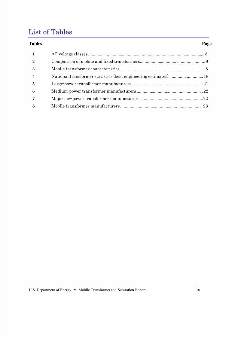
List of Tables
Tables Page
1 AC voltage classes .................................................................................................... 3
2 Comparison of mobile and fixed transformers........................................................8
3 Mobile transformer characteristics .........................................................................8
4 National transformer statistics (best engineering estimates) ............................ 18
5 Large-power transformer manufacturers .............................................................21
6 Medium-power transformer manufacturers ......................................................... 22
7 Major low-power transformer manufacturers ......................................................22
8 Mobile transformer manufacturers....................................................................... 23

8/20/2019 MTS Report to Congress FINAL 73106
http://slidepdf.com/reader/full/mts-report-to-congress-final-73106 10/48
x U.S. Department of Energy Mobile Transformer and Substation Report
8/20/2019 MTS Report to Congress FINAL 73106
http://slidepdf.com/reader/full/mts-report-to-congress-final-73106 11/48
U.S. Department of Energy Mobile Transformer and Substation Report xi
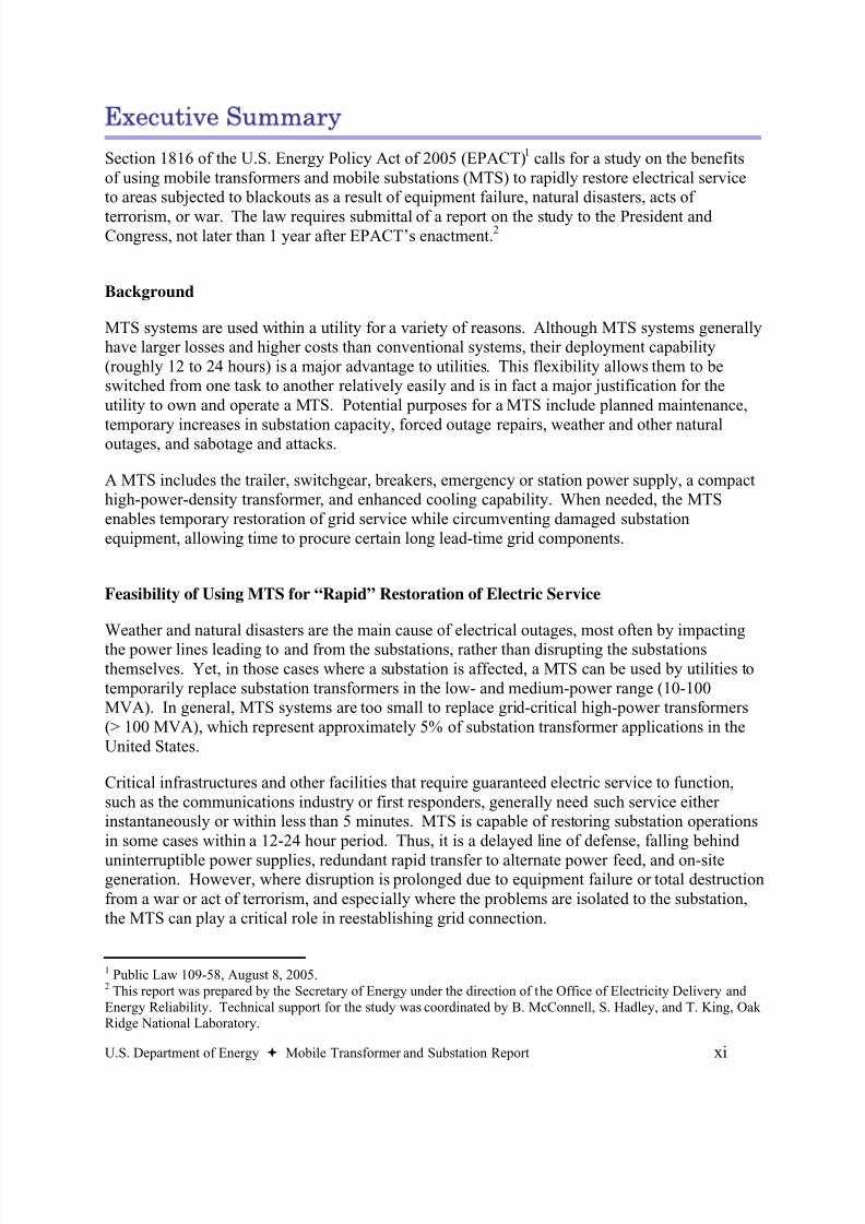
Executive Summary
Section 1816 of the U.S. Energy Policy Act of 2005 (EPACT)1 calls for a study on the benefitsof using mobile transformers and mobile substations (MTS) to rapidly restore electrical serviceto areas subjected to blackouts as a result of equipment failure, natural disasters, acts of
terrorism, or war. The law requires submittal of a report on the study to the President andCongress, not later than 1 year after EPACT’s enactment.
2
Background
MTS systems are used within a utility for a variety of reasons. Although MTS systems generallyhave larger losses and higher costs than conventional systems, their deployment capability(roughly 12 to 24 hours) is a major advantage to utilities. This flexibility allows them to beswitched from one task to another relatively easily and is in fact a major justification for theutility to own and operate a MTS. Potential purposes for a MTS include planned maintenance,
temporary increases in substation capacity, forced outage repairs, weather and other naturaloutages, and sabotage and attacks.
A MTS includes the trailer, switchgear, breakers, emergency or station power supply, a compacthigh-power-density transformer, and enhanced cooling capability. When needed, the MTSenables temporary restoration of grid service while circumventing damaged substationequipment, allowing time to procure certain long lead-time grid components.
Feasibility of Using MTS for “Rapid” Restoration of Electric Service
Weather and natural disasters are the main cause of electrical outages, most often by impacting
the power lines leading to and from the substations, rather than disrupting the substationsthemselves. Yet, in those cases where a substation is affected, a MTS can be used by utilities totemporarily replace substation transformers in the low- and medium-power range (10-100MVA). In general, MTS systems are too small to replace grid-critical high-power transformers(> 100 MVA), which represent approximately 5% of substation transformer applications in theUnited States.
Critical infrastructures and other facilities that require guaranteed electric service to function,such as the communications industry or first responders, generally need such service eitherinstantaneously or within less than 5 minutes. MTS is capable of restoring substation operationsin some cases within a 12-24 hour period. Thus, it is a delayed line of defense, falling behind
uninterruptible power supplies, redundant rapid transfer to alternate power feed, and on-sitegeneration. However, where disruption is prolonged due to equipment failure or total destructionfrom a war or act of terrorism, and especially where the problems are isolated to the substation,the MTS can play a critical role in reestablishing grid connection.
1 Public Law 109-58, August 8, 2005.2 This report was prepared by the Secretary of Energy under the direction of the Office of Electricity Delivery andEnergy Reliability. Technical support for the study was coordinated by B. McConnell, S. Hadley, and T. King, OakRidge National Laboratory.
8/20/2019 MTS Report to Congress FINAL 73106
http://slidepdf.com/reader/full/mts-report-to-congress-final-73106 12/48
xii U.S. Department of Energy Mobile Transformer and Substation Report
Feasibility of using MTS for the Federal Government and Critical Infrastructures
The most obvious users of MTS systems within the Federal Government are the Federal electricutilities, such as the Tennessee Valley Authority, Bonneville Power Authority, and Western AreaPower Administration. They currently use MTS systems for their own systems or those of theirdistribution utility customers. Similar to other utilities, power administrations use MTS systemsfor planned maintenance, temporary capacity increases, forced outage repairs, and weather andother natural outages.
Other possible government users are large military bases. However, most vital emergency powerneeds are usually already provided through on-site generators or redundant grid connections.Yet, the MTS systems can provide a tertiary line of defense to these critical facilities. Jointownership of MTS systems may benefit both large Federal users of power and local utilities.
Although MTS systems can serve a vital role in restoration, the potential value of MTS
systems for restoring electrical service to many critical loads is limited since it is very unusual to find a single critical infrastructure load greater than 3 MVA (lower limit for MTS viability)
where standards, regulations, and emergency back-up procedures do not dictate either on-site
back-up generation or alternate electrical feeds.
Feasibility of Reducing Dependence on Foreign Suppliers of Electrical Grid Components
Foreign producers dominate large-power transformer markets in North America, while medium- power transformers are essentially all produced in North America, with > 60% produced in theUnited States. Mobile systems currently fill the market need for temporary, medium-voltage
transformers and substations (10-100 MVA). Large-power transformers (> 100 MVA) orhigher-voltage transformers (>230 kV) are not currently replaceable using MTS, whiletransformers of 1-10 MVA size are generally available from multiple sources in a relatively shorttime period (2-3 days).
Since MTS are classed as low- and medium-power transformers, increasing or stockpiling
MTS has no effect on the U. S. dependence on foreign production for large-power
transformers. It also has little impact on the low- and medium-power transformer market,
which is already supported by a domestic manufacturing capability.
8/20/2019 MTS Report to Congress FINAL 73106
http://slidepdf.com/reader/full/mts-report-to-congress-final-73106 13/48
U.S. Department of Energy Mobile Transformer and Substation Report 1
BENEFITS OF USING MOBILE
TRANSFORMERS AND MOBILE
SUBSTATIONS FOR RAPIDLY
RESTORING ELECTRICAL SERVICE
1. Introduction
Section 1816 of EPACT calls for a report on the benefits of using mobile transformers andmobile substations (MTS) to rapidly restore electrical service to areas subjected to blackouts as aresult of equipment failure, natural disasters, acts of terrorism, or war. (See Appendix A for theentire text of the section.)
This document is the report to Congress. DOE views the report requirements as consisting oftwo parts: the first, “an analysis of the feasibility of using mobile transformers and mobile
substations to rapidly restore electrical power to military bases; the Federal Government;communications industries; first responders; and other critical infrastructures, as determined bythe Secretary”, is addressed in Section 2 of this report; the second, “an analysis of the feasibilityof using mobile transformers and mobile substations to reduce dependence on foreign entities forkey elements of the electrical grid system of the United States”, is discussed in Section 3 of thisreport.
The report is further organized as follows:
• Section 2, in addressing the rapid restoration of electrical service, provides a broadoverview of how transformers are used within the electric grid and the difference
between stationary and mobile transformers. It also describes the applications for MTSsystems and the rationale for their use.
• Section 3, in analyzing dependence on foreign suppliers, reviews the transformer market,including its overall size, domestic and foreign sources, the manufacturers involved, andother material and labor issues.
• Section 4 presents specific recommendations for the development of MTS systems thatcan serve a vital role in protecting the Nation’s electrical infrastructure.
8/20/2019 MTS Report to Congress FINAL 73106
http://slidepdf.com/reader/full/mts-report-to-congress-final-73106 14/48
2 U.S. Department of Energy Mobile Transformer and Substation Report
2. Rapid Restoration of Electrical Service
2.1 Technology Overview
2.1.1 Description of Grid
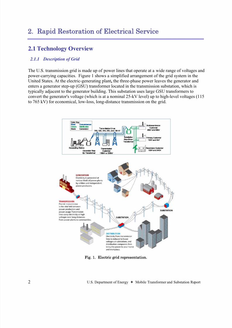
The U.S. transmission grid is made up of power lines that operate at a wide range of voltages and power-carrying capacities. Figure 1 shows a simplified arrangement of the grid system in theUnited States. At the electric-generating plant, the three-phase power leaves the generator andenters a generator step-up (GSU) transformer located in the transmission substation, which istypically adjacent to the generator building. This substation uses large GSU transformers toconvert the generator's voltage (which is at a nominal 25-kV level) up to high-level voltages (115to 765 kV) for economical, low-loss, long-distance transmission on the grid.
Fig. 1. Electric grid representation.
8/20/2019 MTS Report to Congress FINAL 73106
http://slidepdf.com/reader/full/mts-report-to-congress-final-73106 15/48
U.S. Department of Energy Mobile Transformer and Substation Report 3
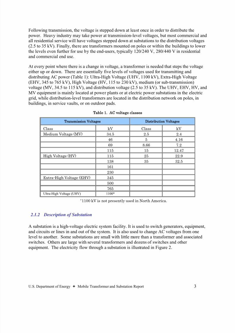
Following transmission, the voltage is stepped down at least once in order to distribute the power. Heavy industry may take power at transmission-level voltages, but most commercial andall residential service will have voltages stepped down at substations to the distribution voltages(2.5 to 35 kV). Finally, there are transformers mounted on poles or within the buildings to lowerthe levels even further for use by the end-users, typically 120/240 V, 280/440 V in residential
and commercial end use.
At every point where there is a change in voltage, a transformer is needed that steps the voltageeither up or down. There are essentially five levels of voltages used for transmitting anddistributing AC power (Table 1): Ultra-High Voltage (UHV, 1100 kV), Extra-High Voltage(EHV, 345 to 765 kV), High Voltage (HV, 115 to 230 kV), medium (or sub-transmission)voltage (MV, 34.5 to 115 kV), and distribution voltage (2.5 to 35 kV). The UHV, EHV, HV, andMV equipment is mainly located at power plants or at electric power substations in the electricgrid, while distribution-level transformers are located in the distribution network on poles, in buildings, in service vaults, or on outdoor pads.
Table 1. AC voltage classes
Transmission Voltages Distribution Voltages
Class kV Class kV
Medium Voltage (MV) 34.5 2.5 2.4
46 5 4.16
69 8.66 7.2
115 15 12.47
High Voltage (HV) 115 25 22.9
138 35 32.5
161
230
Extra-High Voltage (EHV) 345
500
765Ultra-High Voltage (UHV) 1100*
* 1100 kV is not presently used in North America.
2.1.2 Description of Substation
A substation is a high-voltage electric system facility. It is used to switch generators, equipment,
and circuits or lines in and out of the system. It is also used to change AC voltages from onelevel to another. Some substations are small with little more than a transformer and associatedswitches. Others are large with several transformers and dozens of switches and otherequipment. The electricity flow through a substation is illustrated in Figure 2.
8/20/2019 MTS Report to Congress FINAL 73106
http://slidepdf.com/reader/full/mts-report-to-congress-final-73106 16/48
4 U.S. Department of Energy Mobile Transformer and Substation Report
Source: OSHA
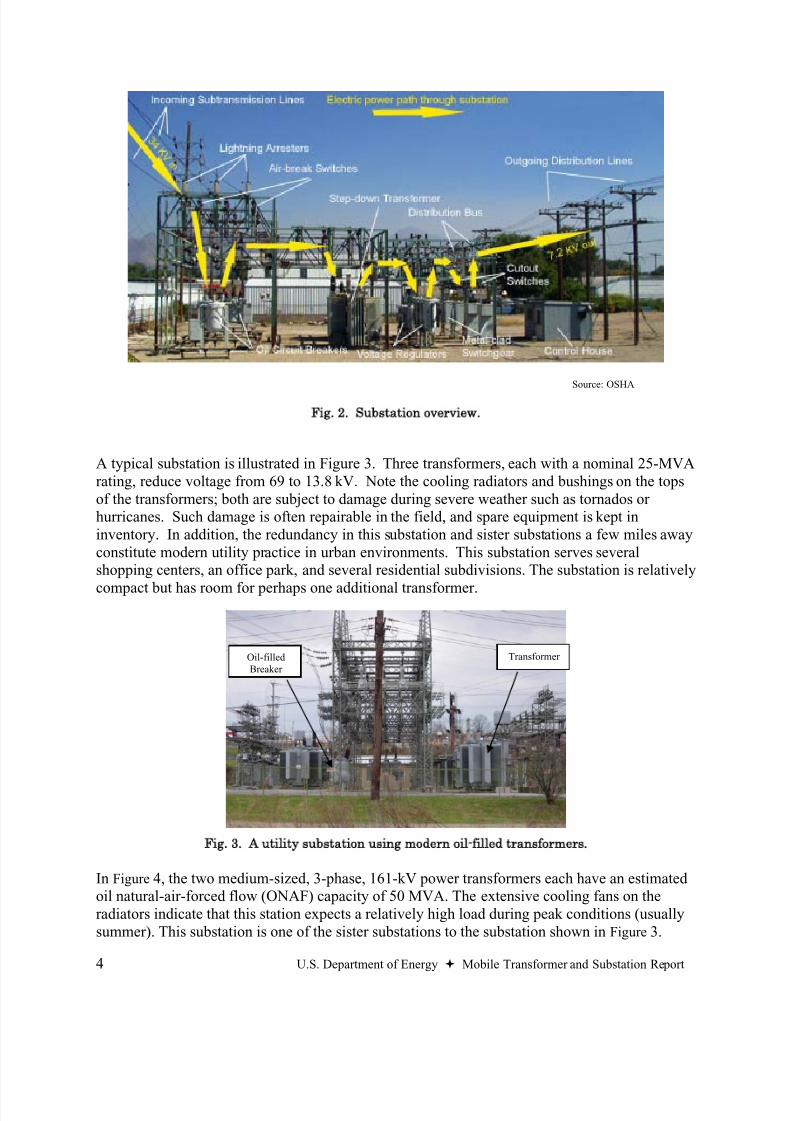
Fig. 2. Substation overview.
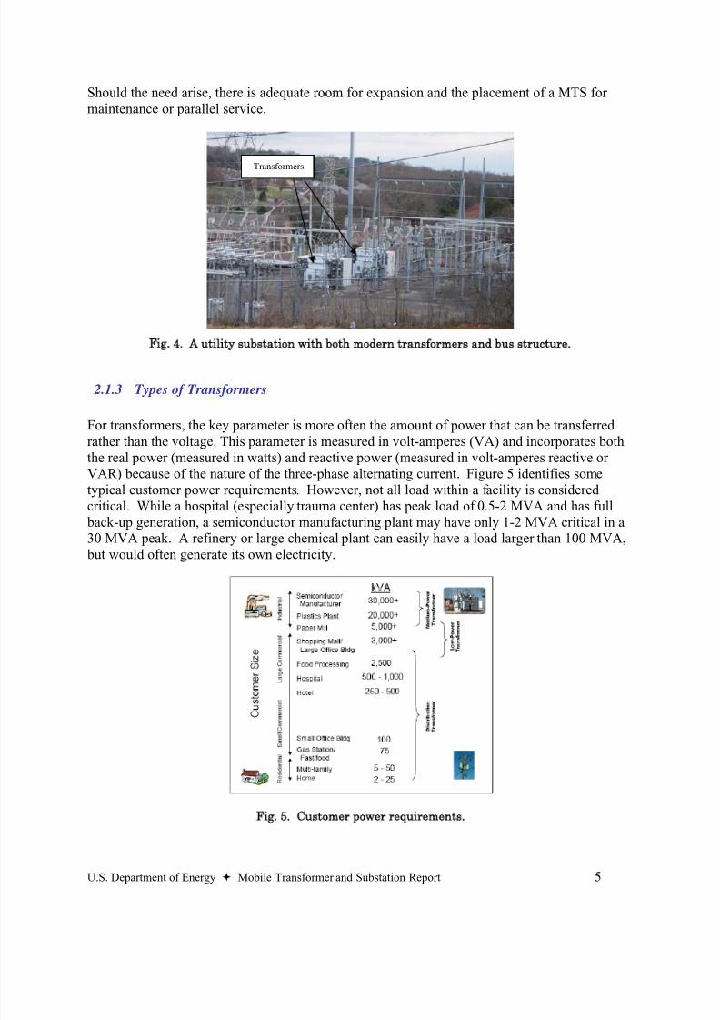
A typical substation is illustrated in Figure 3. Three transformers, each with a nominal 25-MVArating, reduce voltage from 69 to 13.8 kV. Note the cooling radiators and bushings on the topsof the transformers; both are subject to damage during severe weather such as tornados orhurricanes. Such damage is often repairable in the field, and spare equipment is kept ininventory. In addition, the redundancy in this substation and sister substations a few miles awayconstitute modern utility practice in urban environments. This substation serves severalshopping centers, an office park, and several residential subdivisions. The substation is relatively
compact but has room for perhaps one additional transformer.
Fig. 3. A utility substation using modern oil-filled transformers.
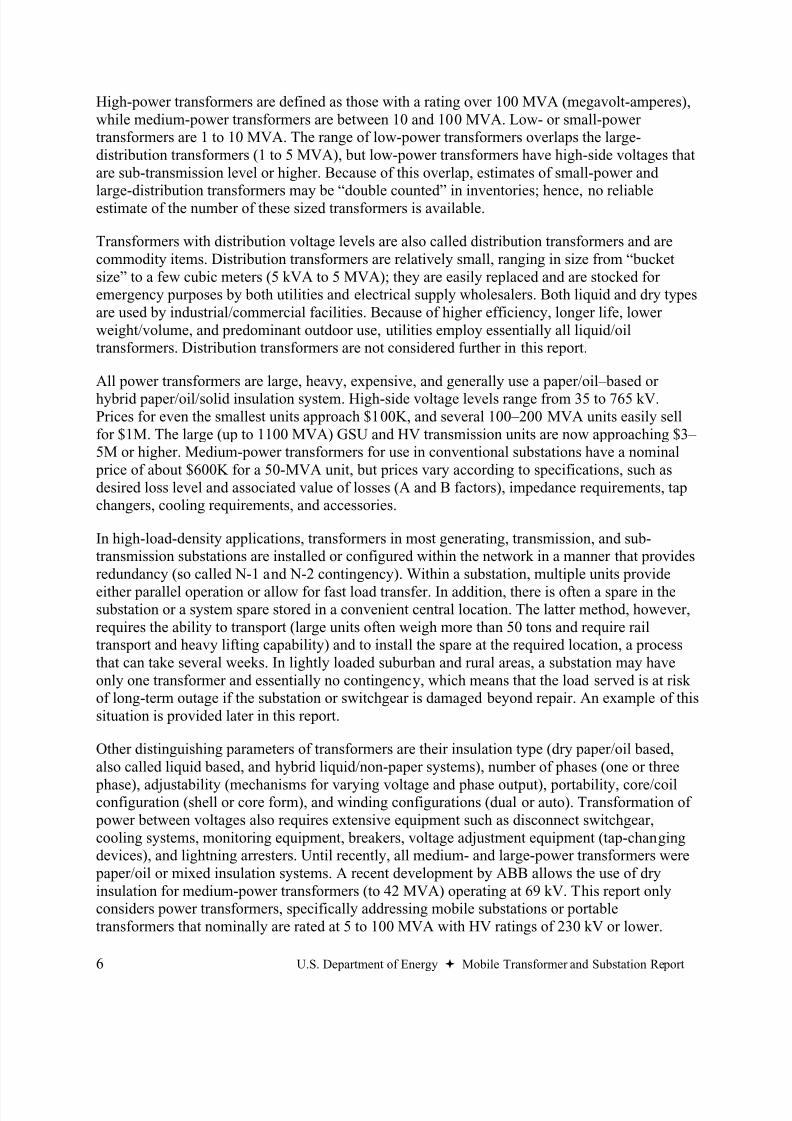
In Figure 4, the two medium-sized, 3-phase, 161-kV power transformers each have an estimatedoil natural-air-forced flow (ONAF) capacity of 50 MVA. The extensive cooling fans on theradiators indicate that this station expects a relatively high load during peak conditions (usuallysummer). This substation is one of the sister substations to the substation shown in Figure 3.
TransformerOil-filledBreaker
8/20/2019 MTS Report to Congress FINAL 73106
http://slidepdf.com/reader/full/mts-report-to-congress-final-73106 17/48
U.S. Department of Energy Mobile Transformer and Substation Report 5
Should the need arise, there is adequate room for expansion and the placement of a MTS formaintenance or parallel service.
Fig. 4. A utility substation with both modern transformers and bus structure.
2.1.3
Types of Transformers
For transformers, the key parameter is more often the amount of power that can be transferredrather than the voltage. This parameter is measured in volt-amperes (VA) and incorporates boththe real power (measured in watts) and reactive power (measured in volt-amperes reactive orVAR) because of the nature of the three-phase alternating current. Figure 5 identifies sometypical customer power requirements. However, not all load within a facility is consideredcritical. While a hospital (especially trauma center) has peak load of 0.5-2 MVA and has full back-up generation, a semiconductor manufacturing plant may have only 1-2 MVA critical in a
30 MVA peak. A refinery or large chemical plant can easily have a load larger than 100 MVA, but would often generate its own electricity.
Fig. 5. Customer power requirements.
Transformers
8/20/2019 MTS Report to Congress FINAL 73106
http://slidepdf.com/reader/full/mts-report-to-congress-final-73106 18/48
6 U.S. Department of Energy Mobile Transformer and Substation Report
High-power transformers are defined as those with a rating over 100 MVA (megavolt-amperes),while medium-power transformers are between 10 and 100 MVA. Low- or small-powertransformers are 1 to 10 MVA. The range of low-power transformers overlaps the large-distribution transformers (1 to 5 MVA), but low-power transformers have high-side voltages thatare sub-transmission level or higher. Because of this overlap, estimates of small-power and
large-distribution transformers may be “double counted” in inventories; hence, no reliableestimate of the number of these sized transformers is available.
Transformers with distribution voltage levels are also called distribution transformers and arecommodity items. Distribution transformers are relatively small, ranging in size from “bucketsize” to a few cubic meters (5 kVA to 5 MVA); they are easily replaced and are stocked foremergency purposes by both utilities and electrical supply wholesalers. Both liquid and dry typesare used by industrial/commercial facilities. Because of higher efficiency, longer life, lowerweight/volume, and predominant outdoor use, utilities employ essentially all liquid/oiltransformers. Distribution transformers are not considered further in this report.
All power transformers are large, heavy, expensive, and generally use a paper/oil–based orhybrid paper/oil/solid insulation system. High-side voltage levels range from 35 to 765 kV.Prices for even the smallest units approach $100K, and several 100–200 MVA units easily sellfor $1M. The large (up to 1100 MVA) GSU and HV transmission units are now approaching $3– 5M or higher. Medium-power transformers for use in conventional substations have a nominal price of about $600K for a 50-MVA unit, but prices vary according to specifications, such asdesired loss level and associated value of losses (A and B factors), impedance requirements, tapchangers, cooling requirements, and accessories.
In high-load-density applications, transformers in most generating, transmission, and sub-transmission substations are installed or configured within the network in a manner that providesredundancy (so called N-1 and N-2 contingency). Within a substation, multiple units provide
either parallel operation or allow for fast load transfer. In addition, there is often a spare in thesubstation or a system spare stored in a convenient central location. The latter method, however,requires the ability to transport (large units often weigh more than 50 tons and require railtransport and heavy lifting capability) and to install the spare at the required location, a processthat can take several weeks. In lightly loaded suburban and rural areas, a substation may haveonly one transformer and essentially no contingency, which means that the load served is at riskof long-term outage if the substation or switchgear is damaged beyond repair. An example of thissituation is provided later in this report.
Other distinguishing parameters of transformers are their insulation type (dry paper/oil based,also called liquid based, and hybrid liquid/non-paper systems), number of phases (one or three
phase), adjustability (mechanisms for varying voltage and phase output), portability, core/coilconfiguration (shell or core form), and winding configurations (dual or auto). Transformation of power between voltages also requires extensive equipment such as disconnect switchgear,cooling systems, monitoring equipment, breakers, voltage adjustment equipment (tap-changingdevices), and lightning arresters. Until recently, all medium- and large-power transformers were paper/oil or mixed insulation systems. A recent development by ABB allows the use of dryinsulation for medium-power transformers (to 42 MVA) operating at 69 kV. This report onlyconsiders power transformers, specifically addressing mobile substations or portabletransformers that nominally are rated at 5 to 100 MVA with HV ratings of 230 kV or lower.
8/20/2019 MTS Report to Congress FINAL 73106
http://slidepdf.com/reader/full/mts-report-to-congress-final-73106 19/48
U.S. Department of Energy Mobile Transformer and Substation Report 7
2.1.4 Description of Mobile Transformers and Substations
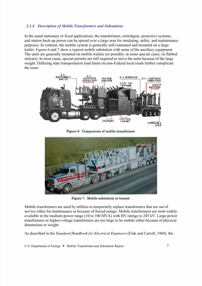
In the usual stationary or fixed applications, the transformers, switchgear, protective systems,and station back-up power can be spread over a large area for insulating, safety, and maintenance purposes. In contrast, the mobile system is generally self-contained and mounted on a large
trailer. Figures 6 and 7 show a typical mobile substation with some of the ancillary equipment.The units are generally mounted on mobile trailers (or possibly, in some special cases, on flatbedrailcars). In most cases, special permits are still required to move the units because of the largeweight. Differing state transportation load limits on non-Federal local roads further complicatethe issue.
Figure 6. Components of mobile transformer.
Figure 7. Mobile substation in transit.
Mobile transformers are used by utilities to temporarily replace transformers that are out ofservice either for maintenance or because of forced outage. Mobile transformers are most widelyavailable in the medium-power range (10 to 100 MVA) with HV ratings to 245 kV. Large-powertransformers or higher-voltage transformers are too large to be mobile either because of physicaldimensions or weight.
As described in the Standard Handbook for Electrical Engineers (Fink and Carroll, 1969), the

8/20/2019 MTS Report to Congress FINAL 73106
http://slidepdf.com/reader/full/mts-report-to-congress-final-73106 20/48
8 U.S. Department of Energy Mobile Transformer and Substation Report
mobile unit is designed to be a multi-purpose package delivering maximum kVAfor allowable weight. Performance and design criteria vary considerably fromthose of a conventional transformer. The margin between the operating voltagelevel of the insulation structure (BIL) and the operating voltage is generallysmaller, the average winding temperature rise over ambient is generally higher,
the overload capability is less ( If only oil/paper is used. It should be noted that formodern Nomex® or hybrid systems, this is not true.), and losses and impedancetend to be higher. The circuitry of the mobile unit is generally more complicated,in order to meet a variety of operating situations in a particular utility system.
Typical mobile transformer characteristics are shown in Tables 2 and 3. High-side voltages rangefrom 35 to 245 kV with sizes ranging from 5 MVA to 100 MVA. Estimates by transformermanufacturers indicate that there are roughly 500 to 600 mobile transformers in service (slightlygreater than 1% of the medium-power transformer inventory). Some of these transformers arequite old but are still serviceable because the number of hours that the mobile transformers areused is much lower than that of fixed installations. Because the mobile units operate at a higher power density than stationary units, losses are higher and, consequently, utilities use them onlyuntil a suitable stationary unit is obtained. According to manufacturers of mobile substations, thecost is about three times the cost of the fixed transformer alone. However, this includes thetrailer, switchgear, breakers, emergency or station power supply, a compact high-power-densitytransformer, and enhanced cooling capability.
Table 2. Comparison of mobile and fixed transformers
Mobile Fixed
Insulation Nomex®/Oil Paper/Oil-Nomex®
Trise (ºC) Up to 115 65
Flux Density 1.78 1.5–1.75
Current Density 4 kA/cm2 0.25–0.5 kA/cm2 Loss Evaluation No Yes
Full Load Losses 1.5% <0.5%
%Z 12–15% <10%
Breakers Yes Substation
Switches Yes Substation
Auxiliary Power Yes Substation
Table 3. Mobile transformer characteristics
Low Nominal High
MVA Rating 5 25 100
HV (kV) 35 115 245
LV (kV) 5 15 115
Total Weight(1000#)
50 95 150
8/20/2019 MTS Report to Congress FINAL 73106
http://slidepdf.com/reader/full/mts-report-to-congress-final-73106 21/48
U.S. Department of Energy Mobile Transformer and Substation Report 9
2.2 Mobile Applications
2.2.1 Rationale for Use of Mobiles
Many of the critical infrastructures in this country rely heavily on electric power for their
continued operation. Certain infrastructures, including the communications industry, publichealth, and government services such as first responders in emergencies, have a crucial role to play in a rapid response to outages. However, the critical infrastructure that would deal mostdirectly with MTS systems is the electric power industry, which owns and operates thesubstations in which MTS systems would be used to replace lost equipment.
The electrical grid is a tightly integrated network that requires precise operation of allcomponents to safely and efficiently provide power to end users. While the vast majority ofoutages are due to power line failures, the grid is also highly vulnerable to disruption atsubstations, where multiple lines intersect. Because substations are nodal points, a single failurecan impact a large number of end users. There are thousands of substations across the country,
and in any year, transformers at some of these will fail or be pulled from service. Unexpectedfailures can seriously disrupt the grid in the surrounding territory. As indicated earlier, there isusually sufficient redundancy in the system to withstand most single-transformer failures;however, substations serving low-load-density areas may not have sufficient contingency toovercome the loss.
MTS systems are used for a variety of reasons within a utility. However, the losses and costsassociated with these systems are generally too high for them to be used as long-termreplacements. In addition, MTS systems have lower impedance, which results in higher faultcurrents, leading to greater stress on grid components such as breakers. Rather, utilities utilizeMTS systems for their main advantage—their rapid deployment capability (roughly 12 to
24 hours). Their flexibility allows them to be switched from one task to another relatively easilyand is in fact a main rationale for a utility to own and operate a MTS. The potential purposes ofan MTS include the following:
Planned maintenanceTemporary substation capacity increasesForced outage repairsWeather and other natural outagesSabotage and attacks
Planned Maintenance
MTS systems are used on a day-to-day basis within the utility to provide alternate capacityduring planned maintenance of substations. Because it is desirable to have MTS systemsavailable for emergency duty during peak loading or extreme weather conditions, utilitiesschedule their planned maintenance around the time when MTS systems are less likely to beneeded for emergency use. Since the utility will have only a limited number of MTS systems,substation repairs must then be staggered or delayed due to unplanned substation transformeroutages.
8/20/2019 MTS Report to Congress FINAL 73106
http://slidepdf.com/reader/full/mts-report-to-congress-final-73106 22/48
10 U.S. Department of Energy Mobile Transformer and Substation Report
Temporary Substation Capacity Increases
MTS systems may be called upon when an area may be faced with a temporary load increase thatis not expected to last more than several months or perhaps a couple of years. Examples areconstruction projects or major plant modifications that require high electrical loads that will dropfollowing completion. Special events can boost the capacity needs for a short time period. An
MTS can be used to avoid the cost of a permanent upgrade that would rarely be used. Anotherexample is to rapidly provide increased substation capacity during peak load conditions prior tosubstation upgrades, in the case where equipment deliveries were delayed or other problemsarose that slowed the capacity expansion.
Forced Outage Repairs
One of the main areas in utility systems where MTS systems could reduce vulnerabilities is inmedium-voltage rural areas without redundancy. Often the grid in these areas is topologically ina radial arrangement that does not allow for the redundancy of parallel circuits. Loss of asubstation or even a key transformer within the substation can cause significant supply problemsdownstream. The Dyersburg example described in Sect. 2.2.3 shows the social and economicimpact of the loss of a substation in regions that do not have multiple feeds.
Unplanned repairs can be called for due to existing equipment failure, weather phenomenon, orintentional disruptions. Equipment failure is the most common rationale for deployment.Lightning can cause a delayed failure or accelerate the aging of critical elements of thetransformer. As transformers age, an increasing percentage of them can face sudden failure.Utilities attempt to monitor transformer conditions such as oil chemistry or load profiles to predict impending failure, but for many reasons, unexpected failures can still occur.
Subsequent to forced outages there are startup issues that should be addressed. The IEEE Recommended Practices for Emergency and Standby Power Systems for Industrial and
Commercial Applications (IEEE, 1987) contains words of caution in the section on startup power. Paragraph 3.3.6 applies to all mobile equipment of all types in emergency situations:“Mobile equipment may suffice if it can be reasonably assumed to be available when needed.(Who has the highest priority when all have the need?)” Section 4.5.6 of the same standardsuggests rental equipment as a viable alternative if mobile power is found to be too expensive(IEEE, 1987).
Weather and Other Natural Outages
Weather and natural disasters are the main cause of electrical outages, although most often thesehave a larger impact on the power lines leading to and from the substations than on thesubstations and transformers themselves. Some natural disasters can harm substation operations
and create a need for MTS systems. The most likely are intense thunderstorms and tornados.Tornados are powerful enough that if they strike a substation, the equipment will generally bedestroyed and require replacement. Floods also can cause massive damage either from the forceof the water or shorting out and thus damaging equipment. It is generally flooding or flyingdebris that causes damage during hurricanes since substations can be designed to withstandhurricane-level winds.
8/20/2019 MTS Report to Congress FINAL 73106
http://slidepdf.com/reader/full/mts-report-to-congress-final-73106 23/48
U.S. Department of Energy Mobile Transformer and Substation Report 11
Sabotage and Attacks
Intentional disruptions such as sabotage could severely harm our Nation’s electrical grid, andmost substations are very vulnerable to attack. Substations are usually unmanned, remote,exposed, and have few physical barriers. Utilities rely more on redundancy of the grid formitigation rather than on hardening of individual sites. The larger sites frequently have personnel
and improved protections, but the consequences of loss of these large sites are comparativelygreater as well. There are few options available for the replacement of a destroyed high-powertransformer. While MTS systems as large as 100 MVA exist, MTS systems are typically below50 MVA in size, with high-side voltages not exceeding 230 kV. High-power transformers, asdescribed above, are greater than 100 MVA and can have high-side voltages of 345 kV or higherand at present can not be backed up by MTS.
MTS systems can play a crucial role in several scenarios involving deliberate attacks. Theultimate target may be a critical infrastructure with limited access to electric power through justone or two medium-power substations. If the facility is vital to area health or other social needsand its substation links are destroyed, MTS systems may be useful in returning the facility to
normal operations more quickly. This may be especially true if the attack strikes severalsubstations, perhaps in order to bring down portions of a large urban area. The choice the utilitymust make is generally between mobile substations and either fixed or mobile emergencygeneration. Even with the use of emergency generation, small mobile transformers may be calledupon to adjust voltages in the area, or to mitigate prolonged disruption.
2.2.2 Industry Experts’ Interviews
A number of utility personnel and consultants were interviewed to determine the appropriate role
that MTS systems play within their company. They identified the categories above as potentialuses for MTS systems, with the main use being substation repair and maintenance. Constructionand maintenance schedules are based on the availability of their MTS, and any delays can causea domino-like rescheduling of other work.
The utilities may share their equipment within their own distribution utilities, but there did notappear to be much sharing of the equipment with other utilities. In some cases, they leaseequipment to preferred customers at reasonable rates. One utility representative mentioned that atransformer serving a coal mine within his utility’s territory had failed and that a MTS was usedto provide continued operation.
One consultant familiar with the industry noted that MTS systems had been used for rebuildingand construction in substations, as temporary substations during construction of a newsubstation, for handling temporary loads that are transient in location like highway construction,and in military applications. Temporary substations had also been needed for new developmentswhere line construction and new substations are behind the budget curve (sometimes for severalyears). Other utility representatives indicated that mobile systems were used for transformerfailure replacements (up to 6 months), feeding isolated areas where service may be curtailed at alater date. A consultant noted that in areas hit by disasters like Hurricane Katrina, these units “area Godsend.” Since large-utility-class transformers require a 6-month to 1-year lead time in anormal economic environment, mobiles are very helpful in these situations.
8/20/2019 MTS Report to Congress FINAL 73106
http://slidepdf.com/reader/full/mts-report-to-congress-final-73106 24/48
12 U.S. Department of Energy Mobile Transformer and Substation Report
2.2.3 Examples of Uses of MTS
Dyersburg, Tennessee
Rural areas typically have electric load density that is both lower and less critical than urbanareas. Often substations will have only a single transformer or at best a set of four single-phaseunits that provide back-up for a single-phase failure. In addition, these rural areas are a radial
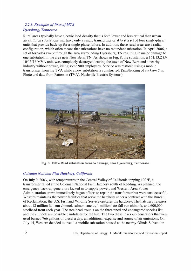
configuration, which often means that substations have no redundant substation. In April 2006, aset of tornados swept through the area surrounding Dyersburg, TN resulting in major damage toone substation in the area near New Bern, TN. As shown in Fig. 8, the substation, a 161/13.2 kV,10/13/16 MVA unit, was completely destroyed leaving the town of New Bern and a nearbyindustry without power, idling some 900 employees. Service was restored using a mobiletransformer from the TVA while a new substation is constructed. (Smith-King of Jackson Sun,Photo and data from Patterson (TVA), Nashville Electric Systems)
Fig. 8. Biffle Road substation tornado damage, near Dyersburg, Tennessee.
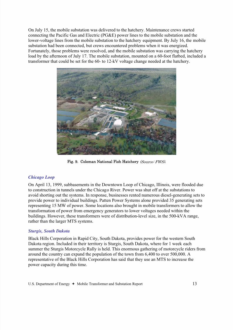
Coleman National Fish Hatchery, California
On July 9, 2003, with temperatures in the Central Valley of California topping 100°F, atransformer failed at the Coleman National Fish Hatchery south of Redding. As planned, the
emergency back-up generators kicked in to supply power, and Western Area PowerAdministration crews immediately began efforts to repair the transformer but were unsuccessful.Western maintains the power facilities that serve the hatchery under a contract with the Bureauof Reclamation; the U.S. Fish and Wildlife Service operates the hatchery. The hatchery releasesabout 12 million fall-run chinook salmon smelts, 1 million late-fall-run chinook, and 600,000steelhead trout each year. The steelhead trout is on the threatened and endangered species list,and the chinook are possible candidates for the list. The two diesel back-up generators that wereused burned 766 gallons of diesel a day, an additional expense and source of air emissions. OnJuly 14, Western decided to install a mobile substation housed at the nearby Olinda Substation.
8/20/2019 MTS Report to Congress FINAL 73106
http://slidepdf.com/reader/full/mts-report-to-congress-final-73106 25/48
U.S. Department of Energy Mobile Transformer and Substation Report 13
On July 15, the mobile substation was delivered to the hatchery. Maintenance crews startedconnecting the Pacific Gas and Electric (PG&E) power lines to the mobile substation and thelower-voltage lines from the mobile substation to the hatchery equipment. By July 16, the mobilesubstation had been connected, but crews encountered problems when it was energized.Fortunately, those problems were resolved, and the mobile substation was carrying the hatchery
load by the afternoon of July 17. The mobile substation, mounted on a 60-foot flatbed, included atransformer that could be set for the 60- to 12-kV voltage change needed at the hatchery.
Fig. 9. Coleman National Fish Hatchery (Source: FWS) .
Chicago Loop
On April 13, 1999, subbasements in the Downtown Loop of Chicago, Illinois, were flooded dueto construction in tunnels under the Chicago River. Power was shut off at the substations toavoid shorting out the systems. In response, businesses rented numerous diesel-generating sets to provide power to individual buildings. Patten Power Systems alone provided 35 generating setsrepresenting 15 MW of power. Some locations also brought in mobile transformers to allow thetransformation of power from emergency generators to lower voltages needed within the buildings. However, these transformers were of distribution-level size, in the 500-kVA range,rather than the larger MTS systems.
Sturgis, South Dakota
Black Hills Corporation in Rapid City, South Dakota, provides power for the western SouthDakota region. Included in their territory is Sturgis, South Dakota, where for 1 week eachsummer the Sturgis Motorcycle Rally is held. This enormous gathering of motorcycle riders fromaround the country can expand the population of the town from 6,400 to over 500,000. Arepresentative of the Black Hills Corporation has said that they use an MTS to increase the power capacity during this time.
8/20/2019 MTS Report to Congress FINAL 73106
http://slidepdf.com/reader/full/mts-report-to-congress-final-73106 26/48
14 U.S. Department of Energy Mobile Transformer and Substation Report
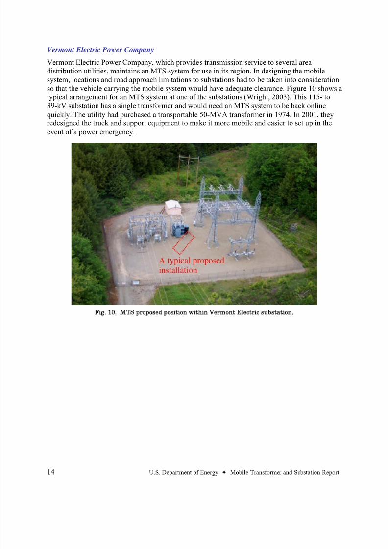
Vermont Electric Power Company
Vermont Electric Power Company, which provides transmission service to several areadistribution utilities, maintains an MTS system for use in its region. In designing the mobilesystem, locations and road approach limitations to substations had to be taken into considerationso that the vehicle carrying the mobile system would have adequate clearance. Figure 10 shows a
typical arrangement for an MTS system at one of the substations (Wright, 2003). This 115- to39-kV substation has a single transformer and would need an MTS system to be back onlinequickly. The utility had purchased a transportable 50-MVA transformer in 1974. In 2001, theyredesigned the truck and support equipment to make it more mobile and easier to set up in theevent of a power emergency.
Fig. 10. MTS proposed position within Vermont Electric substation.
8/20/2019 MTS Report to Congress FINAL 73106
http://slidepdf.com/reader/full/mts-report-to-congress-final-73106 27/48
U.S. Department of Energy Mobile Transformer and Substation Report 15
2.3 Potential Applications in Government
The most obvious users of MTS systems within the Federal Government are the Federal electricutilities, such as the Tennessee Valley Authority (TVA), Bonneville Power Authority (BPA), and
Western Area Power Administration (WAPA). These utilities currently use MTS systems fortheir own systems or those of their distribution utility customers. They may either directly ownthe systems or have agreements with their distribution utility customers that allow them to usethe systems as needed. The Dyersburg and Coleman National Fish Hatchery case studies,discussed in section 2.2.3, are examples of MTS use by TVA and WAPA.
MTS systems are a small fraction of the overall transformation capacity. They cannot beexpected to supplant a large fraction of total government transformation requirements. Thehighest priority government functions already have in place on-site generation and/orredundancy in connections to the grid. The MTS systems can provide a tertiary line of defense tothe critical facilities.
2.3.1 Military Bases
Military bases can have power systems that are about as large as a town. The systems are oftenold and yet in some cases could be critical to our Nation’s national security. In the 1990s,Congress established a policy for privatization of the utilities at military bases. As aconsequence, many of the systems have been sold to contractors or the local utilities.
The Department of Defense Energy Security Policy since 1992 has stated the following:
Policy: It is a basic responsibility of Defense managers and commanders to know thevulnerability of their missions and facilities to energy disruptions, whether the energy sourceis internal or external to the command. Lastly, it is essential to take action to eliminatecritical energy support vulnerabilities. (Morales, 1992)
According to the Department of the Army’s Installation Management Agency (Wilberger, 2004),military facilities are required to develop energy security plans for their facilities, which should be integrated into the installation security plans.
In general, these energy security plans should address utility system vulnerability, emergency preparedness requirements, and remedial actions needed to protect against potential problems. Energy security plans should be consistent with the Army’s strategy to privatizeutilities and reduce the cost of operating and maintaining the utility infrastructure.Installations should clearly define their utility requirements and partner with their local utility
suppliers to meet them. Any remedial actions that run counter to utilities privatization, interms of ownership and operation, must be approved by ASCIM [the Assistant Chief of Stafffor Installation Management]. (Wilberger, 2004)
Based on these directives, military facilities are to work with their local utilities in ensuring thatadequate infrastructures are in place. Rather than own and maintain its own utility equipment, thestrategy is to encourage the privatization of infrastructure. Because the substation anddownstream infrastructure on the bases would be owned by the local utility and if MTS weredeemed necessary in specific cases to ensure energy security, it could be advantageous for both
8/20/2019 MTS Report to Congress FINAL 73106
http://slidepdf.com/reader/full/mts-report-to-congress-final-73106 28/48
16 U.S. Department of Energy Mobile Transformer and Substation Report
the military and the utility to jointly invest in an MTS system. The military base may be of suchcriticality that a spare substation/transformer would be useful, while having such a systemmobile could also be advantageous to the utility since it would then be available in the event ofother substation outages.
2.3.2 Other Federal Government
On Dec. 17, 2003, President Bush signed Homeland Security Presidential Directive (HSPD) - 7that sets the policies of the Government with regard to critical infrastructure. The policy statesthe following:
(7) It is the policy of the United States to enhance the protection of our Nation's criticalinfrastructure and key resources against terrorist acts that could:
(a) cause catastrophic health effects or mass casualties comparable to those from the useof a weapon of mass destruction;
(b) impair Federal departments and agencies' abilities to perform essential missions, orto ensure the public's health and safety;(c) undermine State and local government capacities to maintain order and to deliver
minimum essential public services;(d damage the private sector's capability to ensure the orderly functioning of the
economy and delivery of essential services;(e) have a negative effect on the economy through the cascading disruption of other
critical infrastructure and key resources; or(f) undermine the public's morale and confidence in our national economic and political
institutions.
(8) Federal departments and agencies will identify, prioritize, and coordinate the protectionof critical infrastructure and key resources in order to prevent, deter, and mitigate the effectsof deliberate efforts to destroy, incapacitate, or exploit them. Federal departments andagencies will work with State and local governments and the private sector to accomplish thisobjective. (White, 2003)
Furthermore, HSPD-7 directs all agencies to address the vulnerabilities within their own domain.
(24) All Federal department and agency heads are responsible for the identification, prioritization, assessment, remediation, and protection of their respective internal criticalinfrastructure and key resources. Consistent with the Federal Information SecurityManagement Act of 2002, agencies will identify and provide information security protectionscommensurate with the risk and magnitude of the harm resulting from the unauthorizedaccess, use, disclosure, disruption, modification, or destruction of information. (White, 2003)
Similar to the military bases, most other components of the Federal Government are end-usecustomers for electric power, and are not involved at the level that would put them in control ofsubstations where MTS systems would be applicable. Essential functions are supported by back-up generation. However, if there is a federal facility that is large enough to require a significantfraction of a substation’s output, has a critical need for power, is isolated on the grid, does nothave uninterruptible power supplies, redundant transfer to alternate power feeds or on-site back
8/20/2019 MTS Report to Congress FINAL 73106
http://slidepdf.com/reader/full/mts-report-to-congress-final-73106 29/48
U.S. Department of Energy Mobile Transformer and Substation Report 17
up generation, and that a spare transformer would significantly increase their energy security,then a joint ownership agreement of an MTS with the local utility could be considered. As withthe military base example, the MTS would be useful to the facility for redundancy and of potentially more value to the utility than a spare transformer because of its mobility.
2.3.3 Communications Industry
In June 2006, the Federal Communication Commission released a report on the impact ofHurricane Katrina on telecommunications and media infrastructure. While the panel’s reportemphasizes the severe damage the storm and its aftermath caused to communications systems, italso found that the utility communication systems did not have a significant rate of failure because: 1) the systems were designed to remain intact to aid restoration of electric servicefollowing a significant storm event; 2) they were built with significant on-site back-up powersupplies (batteries and generators); 3) last mile connections to tower sites and the backbonetransport are typically owned by the utility and have redundant paths; and 4) the staff responsiblefor the communications network have a focus on continuing maintenance of network elements(for example, exercising standby generators on a routine basis). ( Section 1(A)(9) )
Telephone systems (and now most cell sites) do not depend on the grid to function. While MTSsystems may play a role in defending against prolonged outages, they fall behind uninterruptible power supplies, redundant transfer to alternate power feeds, and on-site generation as the tools ofchoice for guaranteed electric service immediately after a disruption.
2.3.4 State and Local Government / First Responders
State and local governments are responsible for initial recovery following a disaster. Firstresponders include the local police, fire, emergency medical services (EMS), and state highway patrols. Typically, the facilities of the first responders have internal redundant power systems (ifcritical enough) or back-up generation to enable them to function as long as fuel is available.
These organizations would not directly deploy MTS systems, but rather would assist the localutility in its restoration efforts. MTS systems would be most helpful in restoring power to broader, less critical facilities. However, there may be occasions in rural areas where multiplecritical first-responder facilities are on a non-redundant distribution system, so the substationfeeding the line may have a priority need for an MTS.
8/20/2019 MTS Report to Congress FINAL 73106
http://slidepdf.com/reader/full/mts-report-to-congress-final-73106 30/48
18 U.S. Department of Energy Mobile Transformer and Substation Report
3. Reducing Dependence on Foreign Suppliers
3.1 Market Characteristics
In determining the feasibility of utilizing MTS systems to reduce dependence on foreign
suppliers, it is important to understand current market conditions and characteristics of thetransformer industry. Several key questions will be addressed, including the following:
• What is the overall size of the transformer market?• How many units are installed and who manufactures them?• How many transformers need to be manufactured each year?• What is the relationship between the U.S. market and the worldwide market?• How much of the market is domestically produced?• What is the market for MTS systems as one component of the overall transformer industry?• What are the material and other supply limitations?
3.1.1 Size of Transformer Market
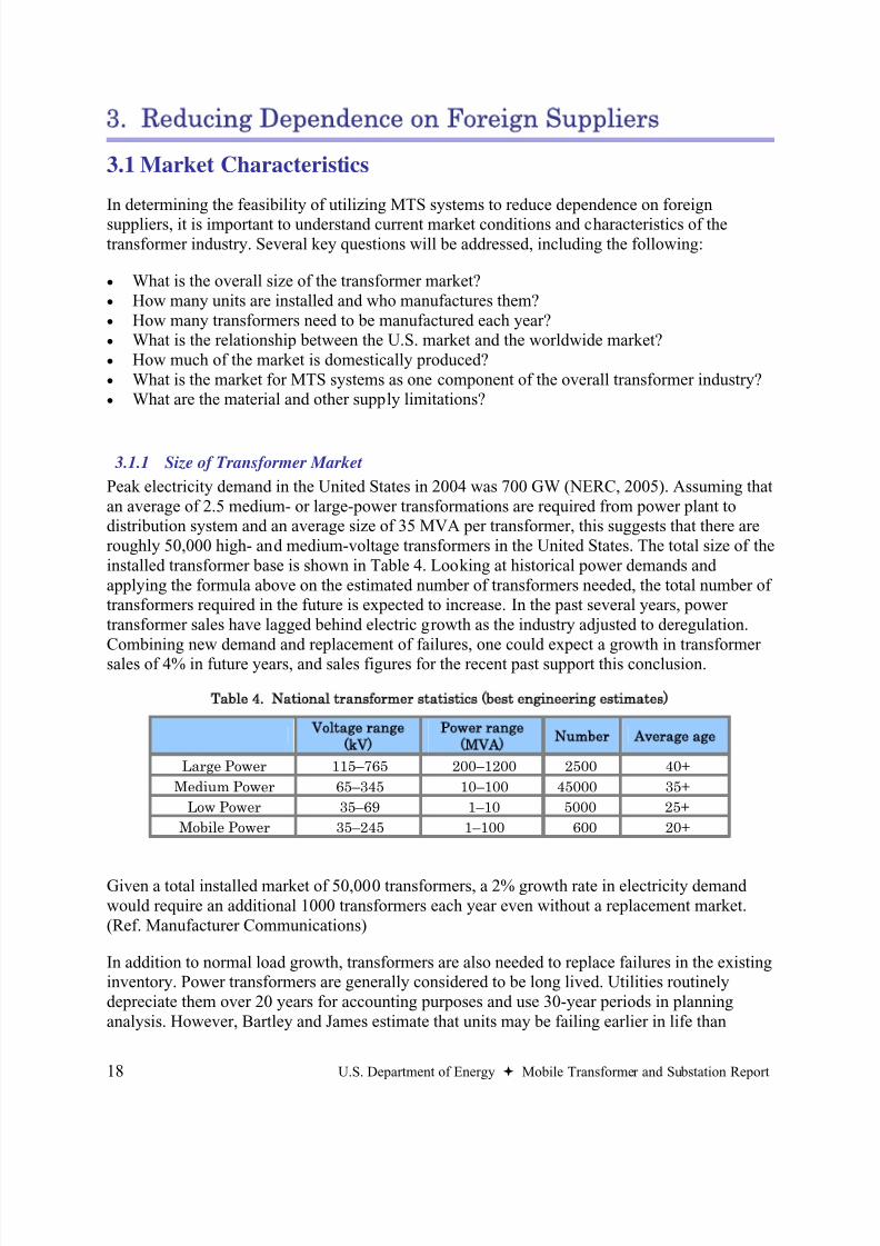
Peak electricity demand in the United States in 2004 was 700 GW (NERC, 2005). Assuming thatan average of 2.5 medium- or large-power transformations are required from power plant todistribution system and an average size of 35 MVA per transformer, this suggests that there areroughly 50,000 high- and medium-voltage transformers in the United States. The total size of theinstalled transformer base is shown in Table 4. Looking at historical power demands andapplying the formula above on the estimated number of transformers needed, the total number oftransformers required in the future is expected to increase. In the past several years, powertransformer sales have lagged behind electric growth as the industry adjusted to deregulation.Combining new demand and replacement of failures, one could expect a growth in transformersales of 4% in future years, and sales figures for the recent past support this conclusion.
Table 4. National transformer statistics (best engineering estimates)
Voltage range
(kV)
Power range
(MVA)
Number Average age
Large Power 115–765 200–1200 2500 40+
Medium Power 65–345 10–100 45000 35+
Low Power 35–69 1–10 5000 25+
Mobile Power 35–245 1–100 600 20+
Given a total installed market of 50,000 transformers, a 2% growth rate in electricity demandwould require an additional 1000 transformers each year even without a replacement market.(Ref. Manufacturer Communications)
In addition to normal load growth, transformers are also needed to replace failures in the existinginventory. Power transformers are generally considered to be long lived. Utilities routinelydepreciate them over 20 years for accounting purposes and use 30-year periods in planninganalysis. However, Bartley and James estimate that units may be failing earlier in life than
8/20/2019 MTS Report to Congress FINAL 73106
http://slidepdf.com/reader/full/mts-report-to-congress-final-73106 31/48
U.S. Department of Energy Mobile Transformer and Substation Report 19
conventional wisdom indicates, with average life at failure being about 14 years for allapplications and 18 years for utilities (Bartley 2003a). However, the average age of the presentlyinstalled units is over 40 years, and there are some in use that are over 70 years old. The ageissue and predicted increase in failures (Bartley 2003a) suggest a possible need for mobiletransformers for emergency and maintenance support. These MTS would temporarily supply
load following failures or assist heavily loaded substations during peak conditions, therebylowering the stress placed on older units.
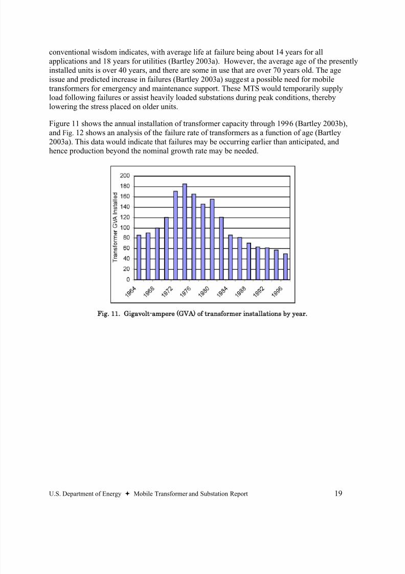
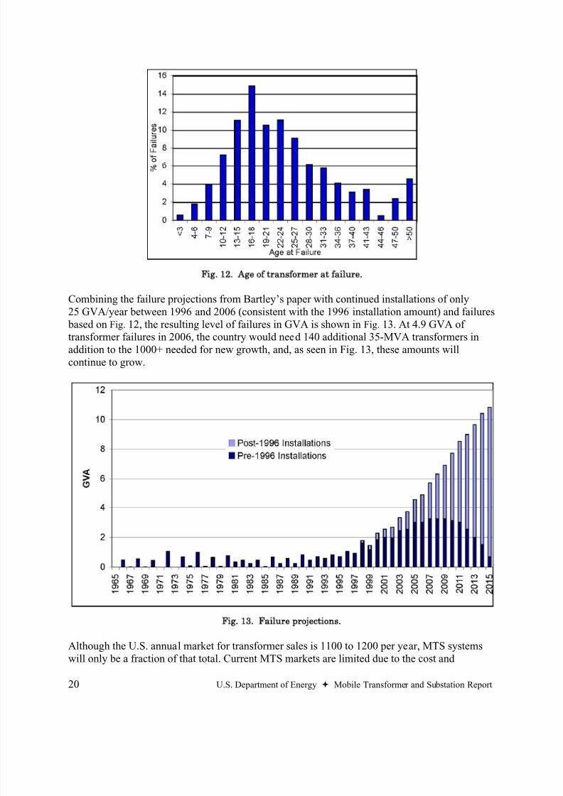
Figure 11 shows the annual installation of transformer capacity through 1996 (Bartley 2003b),and Fig. 12 shows an analysis of the failure rate of transformers as a function of age (Bartley2003a). This data would indicate that failures may be occurring earlier than anticipated, andhence production beyond the nominal growth rate may be needed.
Fig. 11. Gigavolt-ampere (GVA) of transformer installations by year.
8/20/2019 MTS Report to Congress FINAL 73106
http://slidepdf.com/reader/full/mts-report-to-congress-final-73106 32/48
20 U.S. Department of Energy Mobile Transformer and Substation Report
Fig. 12. Age of transformer at failure.
Combining the failure projections from Bartley’s paper with continued installations of only25 GVA/year between 1996 and 2006 (consistent with the 1996 installation amount) and failures based on Fig. 12, the resulting level of failures in GVA is shown in Fig. 13. At 4.9 GVA oftransformer failures in 2006, the country would need 140 additional 35-MVA transformers inaddition to the 1000+ needed for new growth, and, as seen in Fig. 13, these amounts willcontinue to grow.
Fig. 13. Failure projections.
Although the U.S. annual market for transformer sales is 1100 to 1200 per year, MTS systemswill only be a fraction of that total. Current MTS markets are limited due to the cost and
8/20/2019 MTS Report to Congress FINAL 73106
http://slidepdf.com/reader/full/mts-report-to-congress-final-73106 33/48
U.S. Department of Energy Mobile Transformer and Substation Report 21
inefficiencies of the systems compared with non-mobile equipment. While MTS systems areextremely valuable when rapid restoration or other short-term service is required, they are notviable replacements for stationary substations. Currently, there are an estimated 600 MTSsystems in an overall U.S. market of around 50,000 transformers, or 1.2%. As increasingnumbers of transformers age and fail, and as electric reliability becomes more critical to the
Nation’s economy, the use of mobile transformers in proportion to total transformers couldincrease.
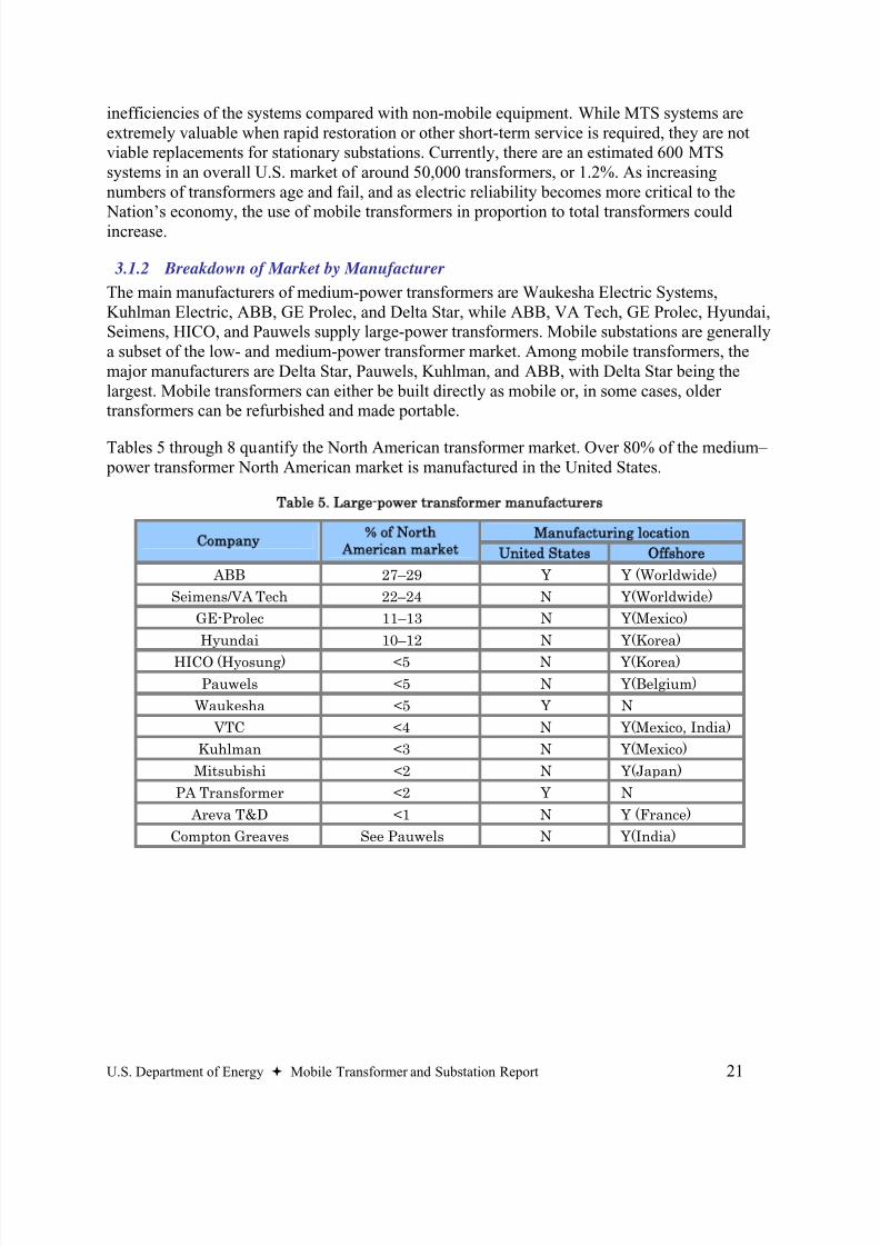
3.1.2 Breakdown of Market by Manufacturer
The main manufacturers of medium-power transformers are Waukesha Electric Systems,Kuhlman Electric, ABB, GE Prolec, and Delta Star, while ABB, VA Tech, GE Prolec, Hyundai,Seimens, HICO, and Pauwels supply large-power transformers. Mobile substations are generallya subset of the low- and medium-power transformer market. Among mobile transformers, themajor manufacturers are Delta Star, Pauwels, Kuhlman, and ABB, with Delta Star being thelargest. Mobile transformers can either be built directly as mobile or, in some cases, oldertransformers can be refurbished and made portable.
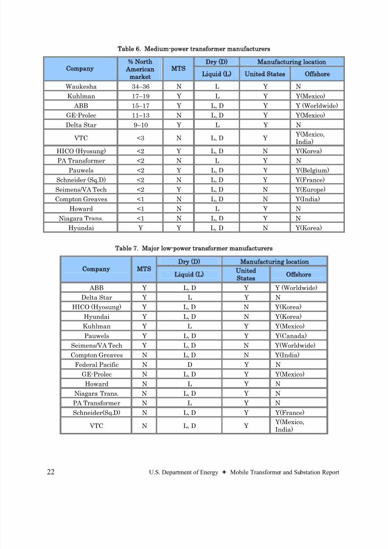
Tables 5 through 8 quantify the North American transformer market. Over 80% of the medium– power transformer North American market is manufactured in the United States.
Table 5. Large-power transformer manufacturers
Manufacturing location
Company
of North
American market
United States Offshore
ABB 27–29 Y Y (Worldwide)
Seimens/VA Tech 22–24 N Y(Worldwide)
GE-Prolec 11–13 N Y(Mexico)
Hyundai 10–12 N Y(Korea)
HICO (Hyosung) <5 N Y(Korea)
Pauwels <5 N Y(Belgium)
Waukesha <5 Y N
VTC <4 N Y(Mexico, India)
Kuhlman <3 N Y(Mexico)
Mitsubishi <2 N Y(Japan)
PA Transformer <2 Y N
Areva T&D <1 N Y (France)
Compton Greaves See Pauwels N Y(India)
8/20/2019 MTS Report to Congress FINAL 73106
http://slidepdf.com/reader/full/mts-report-to-congress-final-73106 34/48
22 U.S. Department of Energy Mobile Transformer and Substation Report
Table 6. Medium-power transformer manufacturers
Dry (D) Manufacturing location
Company
North
American
market
MTS
Liquid (L) United States Offshore
Waukesha 34–36 N L Y N
Kuhlman 17–19 Y L Y Y(Mexico) ABB 15–17 Y L, D Y Y (Worldwide)
GE-Prolec 11–13 N L, D Y Y(Mexico)
Delta Star 9–10 Y L Y N
VTC <3 N L, D Y Y(Mexico,India)
HICO (Hyosung) <2 Y L, D N Y(Korea)
PA Transformer <2 N L Y N
Pauwels <2 Y L, D Y Y(Belgium)
Schneider (Sq.D) <2 N L, D Y Y(France)
Seimens/VA Tech <2 Y L, D N Y(Europe)Compton Greaves <1 N L, D N Y(India)
Howard <1 N L Y N
Niagara Trans. <1 N L, D Y N
Hyundai Y Y L, D N Y(Korea)
Table 7. Major low-power transformer manufacturers
Dry (D) Manufacturing location
Company MTS
Liquid (L)
United
States
Offshore
ABB Y L, D Y Y (Worldwide)Delta Star Y L Y N
HICO (Hyosung) Y L, D N Y(Korea)
Hyundai Y L, D N Y(Korea)
Kuhlman Y L Y Y(Mexico)
Pauwels Y L, D Y Y(Canada)
Seimens/VA Tech Y L, D N Y(Worldwide)
Compton Greaves N L, D N Y(India)
Federal Pacific N D Y N
GE-Prolec N L, D Y Y(Mexico)
Howard N L Y NNiagara Trans. N L, D Y N
PA Transformer N L Y N
Schneider(Sq.D) N L, D Y Y(France)
VTC N L, D Y Y(Mexico,India)
8/20/2019 MTS Report to Congress FINAL 73106
http://slidepdf.com/reader/full/mts-report-to-congress-final-73106 35/48
U.S. Department of Energy Mobile Transformer and Substation Report 23
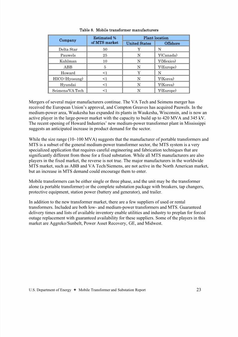
Table 8. Mobile transformer manufacturers
Plant location
Company
Estimated
of MTS market
United States Offshore
Delta Star 50 Y N
Pauwels 25 N Y(Canada)
Kuhlman 10 N Y(Mexico)
ABB 5 N Y(Europe)
Howard <1 Y N
HICO (Hyosung) <1 N Y(Korea)
Hyundai <1 N Y(Korea)
Seimens/VA Tech <1 N Y(Europe)
Mergers of several major manufacturers continue. The VA Tech and Seimens merger hasreceived the European Union’s approval, and Compton Greaves has acquired Pauwels. In themedium-power area, Waukesha has expanded its plants in Waukesha, Wisconsin, and is now an
active player in the large-power market with the capacity to build up to 420 MVA and 345 kV.The recent opening of Howard Industries’ new medium-power transformer plant in Mississippisuggests an anticipated increase in product demand for the sector.
While the size range (10–100 MVA) suggests that the manufacturer of portable transformers andMTS is a subset of the general medium-power transformer sector, the MTS system is a veryspecialized application that requires careful engineering and fabrication techniques that aresignificantly different from those for a fixed substation. While all MTS manufacturers are also players in the fixed market, the reverse is not true. The major manufacturers in the worldwideMTS market, such as ABB and VA Tech/Siemens, are not active in the North American market, but an increase in MTS demand could encourage them to enter.
Mobile transformers can be either single or three phase, and the unit may be the transformeralone (a portable transformer) or the complete substation package with breakers, tap changers, protective equipment, station power (battery and generator), and trailer.
In addition to the new transformer market, there are a few suppliers of used or rentaltransformers. Included are both low- and medium-power transformers and MTS. Guaranteeddelivery times and lists of available inventory enable utilities and industry to preplan for forcedoutage replacement with guaranteed availability for these suppliers. Some of the players in thismarket are Aggreko/Sunbelt, Power Asset Recovery, GE, and Midwest.
8/20/2019 MTS Report to Congress FINAL 73106
http://slidepdf.com/reader/full/mts-report-to-congress-final-73106 36/48
24 U.S. Department of Energy Mobile Transformer and Substation Report
3.1.3 Domestic as Compared to World Market
The world market for electrical equipment ($30.8B) is dominated by ABB, with a 23% share of
world power products (Ref. ABB). For transformers, a $14.8B world market, the keymanufacturers are ABB with 21%, Siemens with 11%, Areva with 6%, and Schneider with 6%.The power transformer share of the world transformer market is about 30%. This suggests thatthe present North American market is about 20% of the world’s total power transformer market.
The ABB global market summary identifies the major issues for the electric grid. For NorthAmerica and South America, there is an aged infrastructure that needs to be refurbished. In theUnited States, reliability concerns and passage of EPACT may trigger T&D investments. In Northern Europe, Central Europe, and the Mediterranean, there is a need for interconnectionsand power-grid upgrades that will require replacement and refurbishment. The power systems ofthe world are experiencing the highest growth in North Asia and China where continued strong
government commitment to power infrastructure is creating the prospect of the world’s mostmodern power grid. Also in South Asia and India, rural electrification is increasing demand for power distribution products and systems with a trend for quality and branding. In the MiddleEast and Africa, the oil and gas sector is the main driver for power T&D.
The largest and fastest growing part of the power transformer market is in China, India, andAsia. In fact the world’s largest power transformer plant is located in Chongqing in central Chinaand is being built by a consortium of ABB, Siemens, and the Chinese government. (Hein) This plant is one of the People’s Republic of China’s flagship factories, and not only will it be theworld’s largest transformer plant, it will also have the world’s largest transformers, which arealso being built by ABB. These units are supplied to the power plant at the Three Gorges Dam.ABB has stated that while the plant is not dependent on the production volume for the ThreeGorges, it is supplying the 12 gigantic transformers for the right wing of the power plant at thedam. The average output of each transformer is 840 MVA, which is enough to supply a largemodern city. Siemens and a Chinese vendor provide the 14 transformers on the other side of the project.
Mobile systems currently fill the market need for temporary, medium-voltage transformers andsubstations. Because they do not directly compete against foreign (or domestic) manufacturing ofstationary transformers, mobile transformers, to some extent, complement foreign manufactureof stationary transformers because they provide a short-term solution until the foreign ordomestic stationary transformer is delivered. The difference in travel time for domestic versusforeign-made transformers may only be a small factor in the overall time to receive the product.
Price and proven performance are the two major issues for purchasers of power transformers.
3.1.4
Material and Labor Supply Issues
The main materials required in the manufacture of a transformer are the low-loss, high-siliconsteel used for the core, the copper used for the windings, and the insulating materials.
Electrical steel, or silicon electrical steel, contains relatively high amounts (3 to 4.5%) of silicon.This addition enhances certain magnetic properties, leading to lower losses and high
8/20/2019 MTS Report to Congress FINAL 73106
http://slidepdf.com/reader/full/mts-report-to-congress-final-73106 37/48
U.S. Department of Energy Mobile Transformer and Substation Report 25
permeability. It is usually in the form of cold-rolled strips, called laminations, that are less than2 mm thick.
There are two main types of electrical steel, grain oriented and non-oriented. Grain-orientedelectrical steel usually has a silicon level of 3% and is processed in such a way that the optimum properties are developed in the coil rolling direction. Power transformers use grain-oriented steelto reduce losses. Electrical steel is usually coated to increase electrical resistance betweenlaminations to lower eddy currents and to provide corrosion resistance. Main domestic suppliersof electric steel are AK Steel and Allegheny Ludlum. Electrical steel is also available fromJapan, India, China, and the European Union. Variation in electrical steel prices can cause largefluctuations in transformer prices.
While aluminum windings are found in distribution transformers, the lower losses and physical properties of copper make it the only real choice for power transformer coils. Copper is acommodity that is traded on world markets, and as with electrical steel, the price of copperstrongly influences the cost of power transformers. According to the Copper DevelopmentAssociation, Chile is the world’s largest producer, followed by the United States. The major producers of the wire used in transformers (magnet wire) are Phelps-Dodge and AlgonquinIndustries Division of Rea.
Several major corporations supply insulating materials. The key players are Weidmann ElectricalTechnology and Dupont. Dupont is the only supplier of the high-temperature insulation system Nomex® that is used alone and with paper/oil hybrid insulation systems for high-power-density,high-temperature operations.
Various analyses by manufacturers and independent market analysts have determined that thereis a current and increasing shortage of basic transformer materials, namely, transformer steel andcopper. Manufacturers indicate that over a two-year period, prices for copper have risen to $4/lb,
a 450% increase, while high-grade H1 core steel has increased 50% over the last year to anominal $2.87/kg. Since copper and steel are the major portions of the cost, power transformer prices have risen very sharply. The major explanation for this is the increased demand for alltransformer materials in the Asian market. Following the law of supply and demand, the twodomestic transformer steel manufacturers are currently supplying a large portion of their spotmarket product to the Asian and Chinese markets.
The production of power transformers is a labor-intensive process, and labor costs constitute 8 to12% of a power transformer’s final cost. Power transformer manufacturers have moved many plants offshore to countries with low labor costs (Mexico, India, China, and Korea) that are alsocloser to the higher demand. While the technical skills needed are not commonplace, the
workforces can be trained relatively quickly.
8/20/2019 MTS Report to Congress FINAL 73106
http://slidepdf.com/reader/full/mts-report-to-congress-final-73106 38/48
26 U.S. Department of Energy Mobile Transformer and Substation Report
4. Conclusions and Recommendations
Rapid Restoration of Electrical Service
MTS systems can serve a vital role in protecting the Nation’s electrical infrastructure. Theirflexibility allows them to switch from one purpose to another relatively easily. When needed,the MTS enables temporary restoration of grid service while circumventing damaged substationequipment, allowing time to procure certain long lead-time grid components.
However, for seamless continuity of operation, it is critical that there is virtually a continuoussupply of electricity. This can only occur through uninterruptible power supplies (e.g. batteries),redundant power feeds, and on-site generation. Yet, where disruption is prolonged due toequipment failure or total destruction from a war or act of terrorism, and especially where the problems are isolated to the substation, the MTS can play a critical role in reestablishing gridconnections.
Supply for Prioritized Government Functions
Government facilities and local utilities know their systems’ redundancy and needs. Local utilityinvolvement is crucial since most components of the federal government are end-use customersfor electric power and are not involved at the level that would put them in control of thesubstations where MTS systems could be applicable. For cases that have been identified throughexisting processes to have a need for additional redundancy and for which MTS systems makegood economic and security sense, there may be some justification for the government toconsider through single or joint ownership. However, because of the variety of ways emergency
power can be provided, each case should be considered independently.
Regulatory
A fixed substation is considered part of the transmission and distribution (T&D) grid. Althoughmobile substations and mobile transformers are not a permanent part of the grid structure; they play a vital role in maintaining the reliability and security of a utility's grid system. Theavailability of mobile transformers and mobile substations enables system operators to rapidlyrestore electrical service where there is equipment failure, forced outage repairs, naturaldisasters, and acts of terrorism. When mobile transformers and mobile substations are used torestore electrical service in such situations, they function as part of the permanent grid system.In effect, they are an integral and critical part of the utility's electrical system. Accordingly, aninvestment in technologies like this to address reliability and security concerns may be prudent intoday’s operating environment and should not be discouraged simply because the technologiesare unconventional.
Reducing Dependence on Foreign Suppliers
Foreign producers dominate large-power transformer markets in North America, while medium- power transformers are essentially all produced in North America, with > 60% produced in theUnited States. Mobile systems currently fill the market need for temporary, medium-voltage
8/20/2019 MTS Report to Congress FINAL 73106
http://slidepdf.com/reader/full/mts-report-to-congress-final-73106 39/48
U.S. Department of Energy Mobile Transformer and Substation Report 27
transformers and substations (10-100 MVA). Large-power transformers (> 100 MVA) orhigher-voltage transformers (>230 kV) are not currently replaceable using MTS, whiletransformers of 1-10 MVA size are generally available from multiple sources in a relatively shorttime period (2-3 days).
MTS are classed as low- and medium-power transformers and has no effect on the U. S.dependence on foreign production for large-power transformers. The low- and medium-powertransformer market is already supported by a domestic manufacturing capability. In addition, because they do not directly compete against foreign (or domestic) manufacturing of stationarytransformers, mobile transformers, to some extent, complement the manufacture of stationarytransformers because they provide a short-term solution until the foreign or domestic stationarytransformer is delivered.

8/20/2019 MTS Report to Congress FINAL 73106
http://slidepdf.com/reader/full/mts-report-to-congress-final-73106 40/48
28 U.S. Department of Energy Mobile Transformer and Substation Report
8/20/2019 MTS Report to Congress FINAL 73106
http://slidepdf.com/reader/full/mts-report-to-congress-final-73106 41/48
U.S. Department of Energy Mobile Transformer and Substation Report 29
5. References
ABB Power Products Division and ABB Power Systems, ABB Products, systems, services in
power: An overview, ABB library and database located at:http://www.abb.com/global/veabb/veabb051.nsf/0/d78692ef1282021ec1257164006f0dd9/$file/p
resentationpt.pdf
Bartley, William H. and Rowland I. James, “Transformer Asset Management,” 2003 SecondAnnual Technical Conference on New Diagnostic Concepts for Better Asset Management November 10-12, 2003 Radisson Deauville Resort, Miami Beach, FL (Bartley 2003a).
Bartley, William H., “Investigating Transformer Failures,” 2003 Third Annual TechnicalConference on New Diagnostic Concepts for Better Asset Management November 8-10, 2004Holiday Inn Capitol Plaza, Sacramento, CA (Bartley 2003b).
Delta Star and Waukesha Electric Systems (Communications concerning market demand and
existing inventory. Mobile systems from Delta Star and fixed systems from Waukesha. Inaddition, the Energy Information Agency energy growth projections, the National ElectricalManufacturers Association production database and other private market projections, such asthose from Frost & Sullivan (www.frost.com) are used to estimate existing and future marketsand market share.)
Hein, Christoph, The worlds biggest transformer plant is operating at full capacity, Frankfurter
Allgemeine Zeitung, April 21, 2006. Article at the ABB library archives:http://www.abb.com/global/abbzh/abbzh251.nsf!OpenDatabase&db=/global/seitp/seitp321.nsf&v=9AAC750000&e=us&m=9F2&c=4AA7ACF50738D3B3C1256EE600420386
Independent Panel Reviewing the Impact of Hurricane Katrina on Communications Networks:
Report and Recommendations to the Federal Communications Commission, June 12, 2006
Morales, D.K. 1992, Defense Energy Program Policy Memorandum (DEPPM) 92-1, Office ofthe Assistant Secretary of Defense, January 14.
Nashville Electric Systems Press Release(http://www.nespower.com/press_releases/p040306a.aspx)
NERC (2005), Electricity Supply and Demand Database, North American Electric ReliabilityCouncil, September. http://www.nerc.com/~esd/
Patterson TVA (Communication with Oak Ridge National Laboratory, use approved by TVA)
Smith-King, Tonya “Recovery on as scarred locals look to skies in dread,”, Jackson Sun April 7,2006 ( See also http://www.jacksonsun.com/apps/pbcs.dll/frontpage )
Stiegemeir, Craig L. and Ramsis Giris, Rapidly Deployable Recovery Transformers, IEEE
Power and Energy Magazine, March/April 2006.
The White House 2003, Homeland Security Presidential Directive/HSPD-7 , Dec. 17.http://www.whitehouse.gov/news/releases/2003/12/20031217-5.html
8/20/2019 MTS Report to Congress FINAL 73106
http://slidepdf.com/reader/full/mts-report-to-congress-final-73106 42/48
30 U.S. Department of Energy Mobile Transformer and Substation Report
Wilberger, Col. S.T. 2004, Energy Security Plans, SFIM-OP-P, Department of the ArmyInstallation Management Agency, March 29.
Wright, Jeffery M., Matt McCormack and Norman Field, The Retrofit of a Transportable
Transformer to a Mobile, Vermont Electric Power Company, presented to 2003 Third Annual New Diagnostic Concepts for Better Asset Management November 10-12, 2003 RadissonDeauville Resort, Miami Beach, FL. See http://www.weidmann-acti.com/u/library/2003wrightpaper.pdf (Wright 2003).
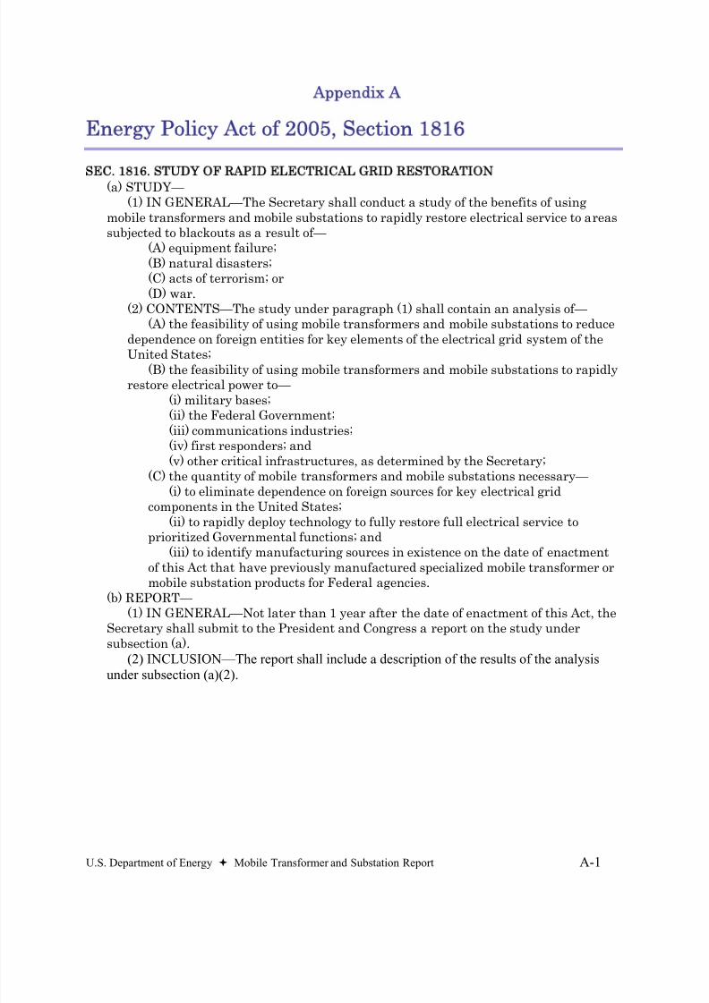
8/20/2019 MTS Report to Congress FINAL 73106
http://slidepdf.com/reader/full/mts-report-to-congress-final-73106 43/48
U.S. Department of Energy Mobile Transformer and Substation Report A-1
Appendix A
Energy Policy Act of 2005, Section 1816
SEC. 1816. STUDY OF RAPID ELECTRICAL GRID RESTORATION(a) STUDY—(1) IN GENERAL—The Secretary shall conduct a study of the benefits of using
mobile transformers and mobile substations to rapidly restore electrical service to areassubjected to blackouts as a result of—
(A) equipment failure;(B) natural disasters;(C) acts of terrorism; or(D) war.
(2) CONTENTS—The study under paragraph (1) shall contain an analysis of—(A) the feasibility of using mobile transformers and mobile substations to reduce
dependence on foreign entities for key elements of the electrical grid system of the
United States;(B) the feasibility of using mobile transformers and mobile substations to rapidly
restore electrical power to—(i) military bases;(ii) the Federal Government;(iii) communications industries;(iv) first responders; and(v) other critical infrastructures, as determined by the Secretary;
(C) the quantity of mobile transformers and mobile substations necessary—(i) to eliminate dependence on foreign sources for key electrical grid
components in the United States;
(ii) to rapidly deploy technology to fully restore full electrical service toprioritized Governmental functions; and(iii) to identify manufacturing sources in existence on the date of enactment
of this Act that have previously manufactured specialized mobile transformer ormobile substation products for Federal agencies.
(b) REPORT—(1) IN GENERAL—Not later than 1 year after the date of enactment of this Act, the
Secretary shall submit to the President and Congress a report on the study undersubsection (a).
(2) INCLUSION—The report shall include a description of the results of the analysisunder subsection (a)(2).

8/20/2019 MTS Report to Congress FINAL 73106
http://slidepdf.com/reader/full/mts-report-to-congress-final-73106 44/48
A-2 U.S. Department of Energy Mobile Transformer and Substation Report
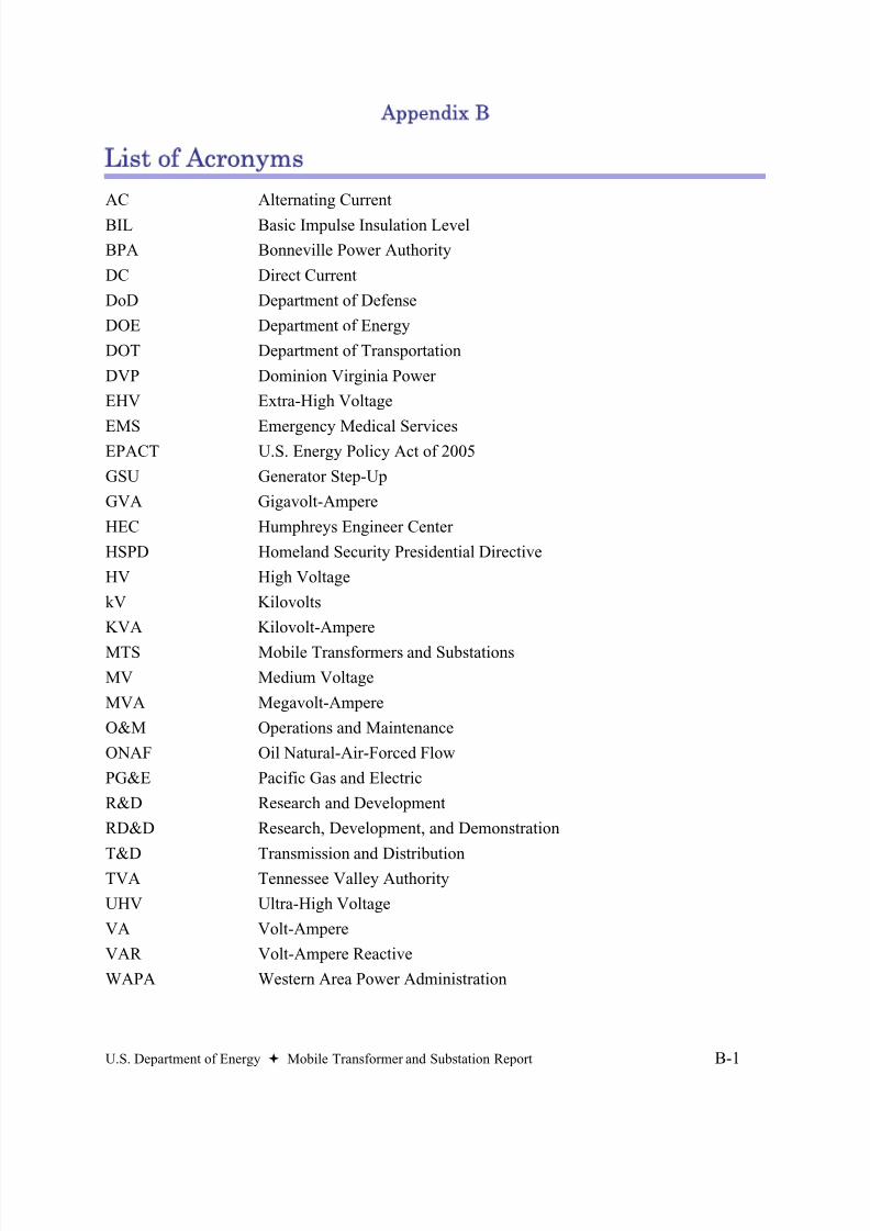
8/20/2019 MTS Report to Congress FINAL 73106
http://slidepdf.com/reader/full/mts-report-to-congress-final-73106 45/48
U.S. Department of Energy Mobile Transformer and Substation Report B-1
Appendix B
List of Acronyms
AC Alternating Current
BIL Basic Impulse Insulation Level
BPA Bonneville Power Authority
DC Direct Current
DoD Department of Defense
DOE Department of Energy
DOT Department of Transportation
DVP Dominion Virginia Power
EHV Extra-High Voltage
EMS Emergency Medical ServicesEPACT U.S. Energy Policy Act of 2005
GSU Generator Step-Up
GVA Gigavolt-Ampere
HEC Humphreys Engineer Center
HSPD Homeland Security Presidential Directive
HV High Voltage
kV Kilovolts
KVA Kilovolt-Ampere
MTS Mobile Transformers and Substations
MV Medium Voltage
MVA Megavolt-Ampere
O&M Operations and Maintenance
ONAF Oil Natural-Air-Forced Flow
PG&E Pacific Gas and Electric
R&D Research and Development
RD&D Research, Development, and Demonstration
T&D Transmission and Distribution
TVA Tennessee Valley Authority
UHV Ultra-High Voltage
VA Volt-Ampere
VAR Volt-Ampere Reactive
WAPA Western Area Power Administration

8/20/2019 MTS Report to Congress FINAL 73106
http://slidepdf.com/reader/full/mts-report-to-congress-final-73106 46/48
B-2 U.S. Department of Energy Mobile Transformer and Substation Report
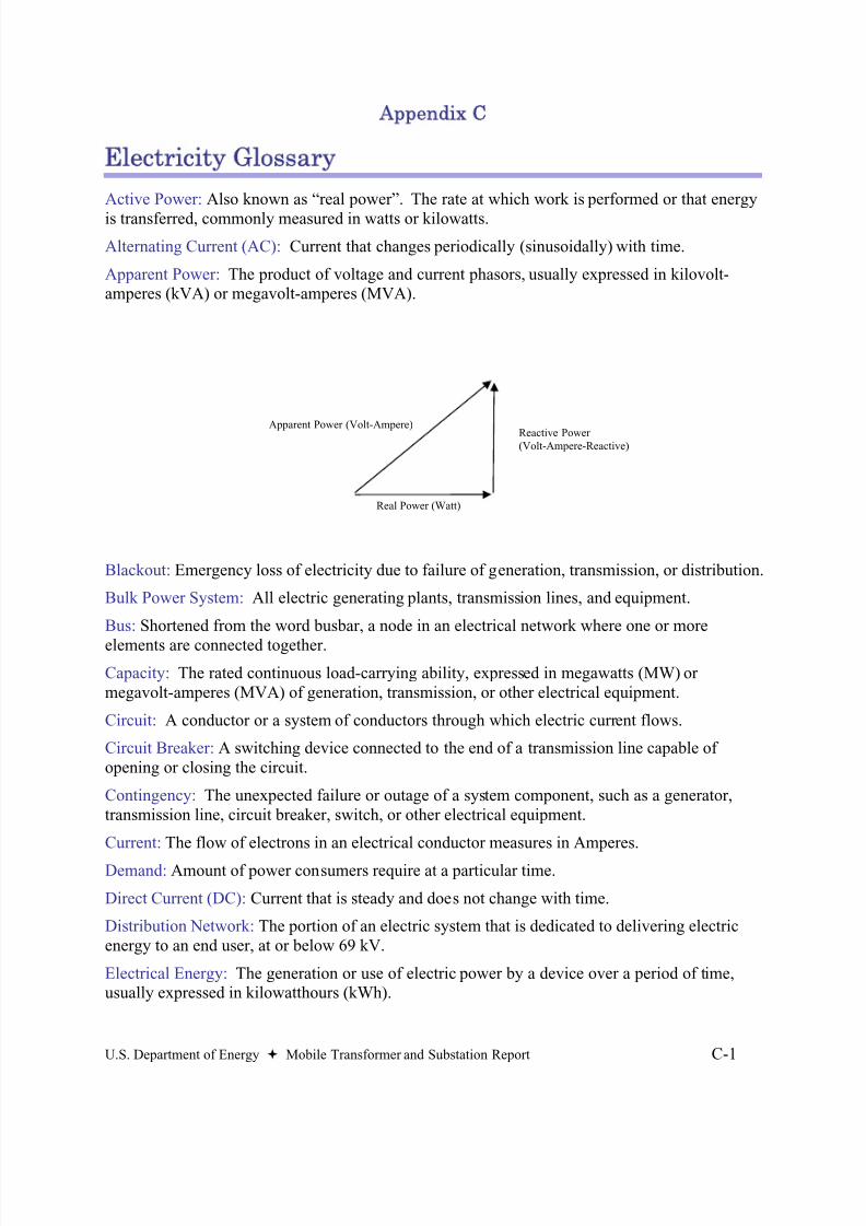
8/20/2019 MTS Report to Congress FINAL 73106
http://slidepdf.com/reader/full/mts-report-to-congress-final-73106 47/48
U.S. Department of Energy Mobile Transformer and Substation Report C-1
Appendix C
Electricity Glossary
Active Power: Also known as “real power”. The rate at which work is performed or that energy
is transferred, commonly measured in watts or kilowatts.
Alternating Current (AC): Current that changes periodically (sinusoidally) with time.
Apparent Power: The product of voltage and current phasors, usually expressed in kilovolt-amperes (kVA) or megavolt-amperes (MVA).
Blackout: Emergency loss of electricity due to failure of generation, transmission, or distribution.
Bulk Power System: All electric generating plants, transmission lines, and equipment.
Bus: Shortened from the word busbar, a node in an electrical network where one or more
elements are connected together.
Capacity: The rated continuous load-carrying ability, expressed in megawatts (MW) ormegavolt-amperes (MVA) of generation, transmission, or other electrical equipment.
Circuit: A conductor or a system of conductors through which electric current flows.
Circuit Breaker: A switching device connected to the end of a transmission line capable ofopening or closing the circuit.
Contingency: The unexpected failure or outage of a system component, such as a generator,transmission line, circuit breaker, switch, or other electrical equipment.
Current: The flow of electrons in an electrical conductor measures in Amperes.
Demand: Amount of power consumers require at a particular time.
Direct Current (DC): Current that is steady and does not change with time.
Distribution Network: The portion of an electric system that is dedicated to delivering electricenergy to an end user, at or below 69 kV.
Electrical Energy: The generation or use of electric power by a device over a period of time,usually expressed in kilowatthours (kWh).
Real Power (Watt)
Reactive Power(Volt-Ampere-Reactive)
Apparent Power (Volt-Ampere)
8/20/2019 MTS Report to Congress FINAL 73106
http://slidepdf.com/reader/full/mts-report-to-congress-final-73106 48/48
Fault: Refers to some abnormal system condition, usually means a short circuit.
Generation (Electricity): The process of producing electrical energy from other forms of energy.
Generator: Generally, an electromechanical device used to convert mechanical power toelectrical power.
Grid: An electrical transmission and/or distribution network.
High Voltage Lines: Used to transmit power between utilities. The definition of “high” varies, but it is opposed to “low” voltage lines that deliver power to homes and most businesses.
Load (Electric): The amount of electric power delivered or required at any specific point or points on a system.
Outage: The period during which a generating unit, transmission line, or other facility is out ofservice.
Power/Phase Angle: The angular relationship between an ac (sinusoidal) voltage across a circuitelement and the ac (sinusoidal) current through it.
Protective Relay: A device designed to detect abnormal system conditions and initiate theoperation of circuit breakers or other control equipment.
Reactive Power: The portion of electricity that establishes and sustains the electric and magneticfields of alternating-current equipment. It is usually expressed in kilovars (kVAR) or megavars(MVAR). Reactive power must be supplied to most types of equipment with windings, such asmotors and transformers.
Real Power: See “Active Power”.
Relay: A device that controls the opening and subsequent reclosing of circuit breakers.
Reliability: The degree of performance of the elements of the bulk power system that results in
electricity being delivered to customers within accepted standards and in the amount desired.Security: The ability of the electric system to withstand sudden disturbances.
Stability: The ability of an electric system to maintain a state of equilibrium during normal andabnormal system conditions or disturbances.
Substation: Facility equipment that switches, changes, or regulates electric voltage.
Switching Station: Facility equipment used to tie together two or more electric circuits throughswitches.
Transformer: A device that operates on magnetic principles to increase (step up) or decrease(step down) voltage.
Transmission: An interconnected group of lines and associate equipment for the movement ofelectric energy between points of supply and points at which it is transferred for delivery tocustomers or is delivered to other electric systems.
Voltage: The electrical force, or “pressure”, that causes current to flow in a circuit, measured involts