Embed Size (px)
Citation preview

Mueser Rutledge Consulting Engineers 14 Penn Plaza · 225 West 34th Street · New York, NY 10122 Tel: (917) 339-9300 · Fax: (917) 339-9400 www.mrce.com
MEMORANDUM Date: January 2016 To: Office From: Zenon Markewycz Re: EE Memo 3 – Loading on Promenade Sheet Piles
Wills St. Promenade, Harbor Point, Baltimore, MD File: 12582B - 130
MRCE has completed a review of the available information and evaluation of the existing permanent sheet pile wall at the foot of Wills Street. The purpose of this analysis is to assess ability of the existing sheet pile wall to support the proposed grade change. Exhibits
1. DS-1a Existing AZ-13 Sheet pile Wall Section 2. DS-1b Proposed Modifications to AZ-13 Sheet pile Wall Section 3. DS-2a Existing BZ-26 Bulkhead Wall Section 4. DS-2b Proposed Modifications to BZ-26 Sheet pile Wall Section – Anchored Option 5. DS-2c Proposed Modifications to BZ-26 Sheet pile Wall Section – Rip Rap Option MRCE 12582,
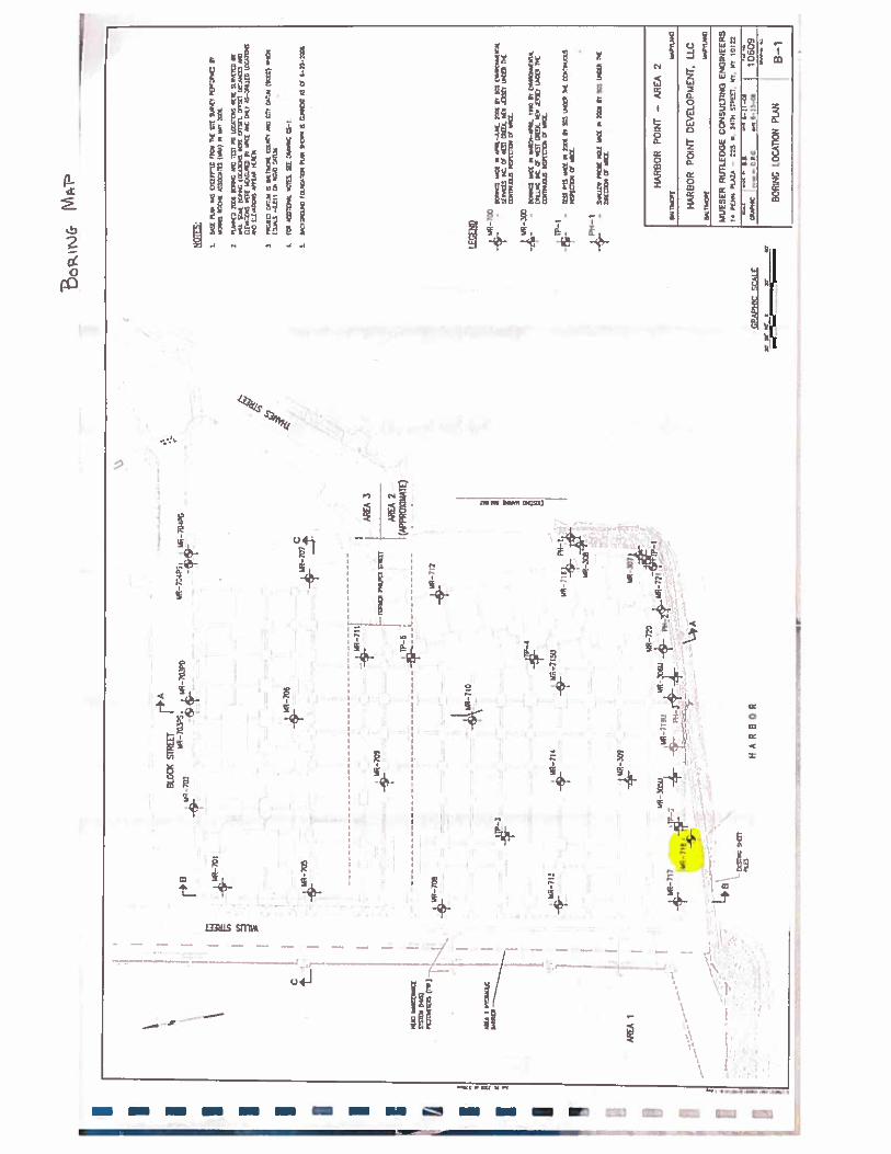
Wills Wharf Office / Hotel; Drawing DDP F1.40 – Foundation Plan, December 2015 6. MRCE 10609, Harbor Point – Area 2; Drawing B-1 – Boring Location Plan, June 2006 7. MRCE 10609, Thames Street Wharf Office Building & Garage
a. Drawing F1.03 – Promenade and Sheeting Plan, October 2007 b. Drawing F2.02 – Sections and Details, October 2007 c. Drawing F2.03 – Sections and Details, October 2007
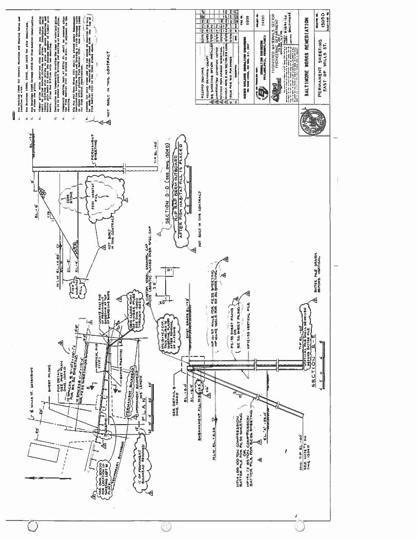
8. MRCE 6909, Baltimore Works Remediation a. Drawing 1300D - Sheeting and Shoring General Plan, December 1992
9. Drawing 1305D – Permanent Sheeting East of Wills Street, December 1992 References
1. MRCE 10609, Geotechnical Data Report Harbor Point Areas 2 and 3 Philpot and Block Sts., between Wills & Thames, Boring No. MR-718, June 2006
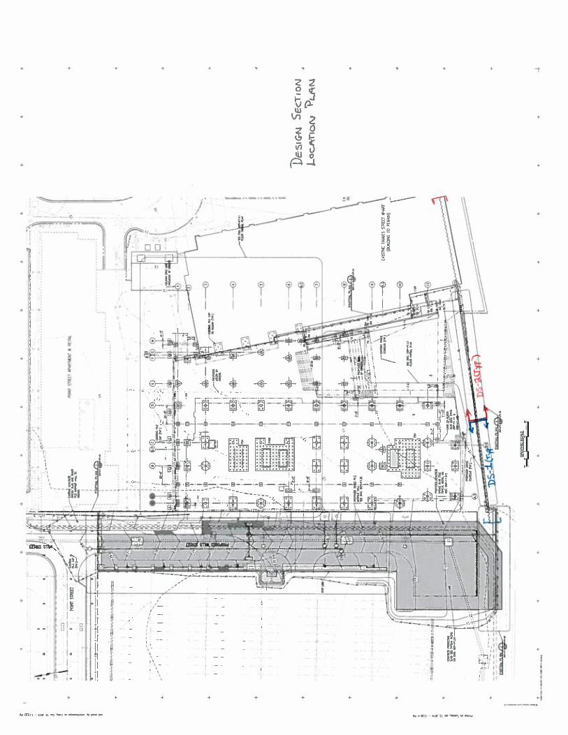
Existing Sheet Pile Wall The existing sheet pile wall is located at the south end of the proposed Wills Street Extension and runs east along the shoreline to the Thames Street Wharf Promenade, serving to retain backfilled material. The sheet pile wall consists of two continuous segments represented by Design Section 1a (DS-1a) and Design Section 2a (DS-2a). DS-1a represents the eastern segment starting just east of column line D.7 as shown on Drawing F1.03 and running approx. 114 ft., towards the west. Along this segment, the existing grade is assumed to be at

January, 2016 Page 2 of 2
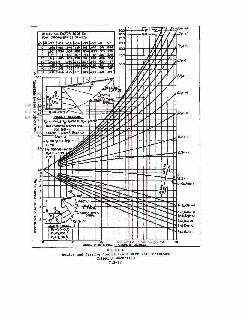
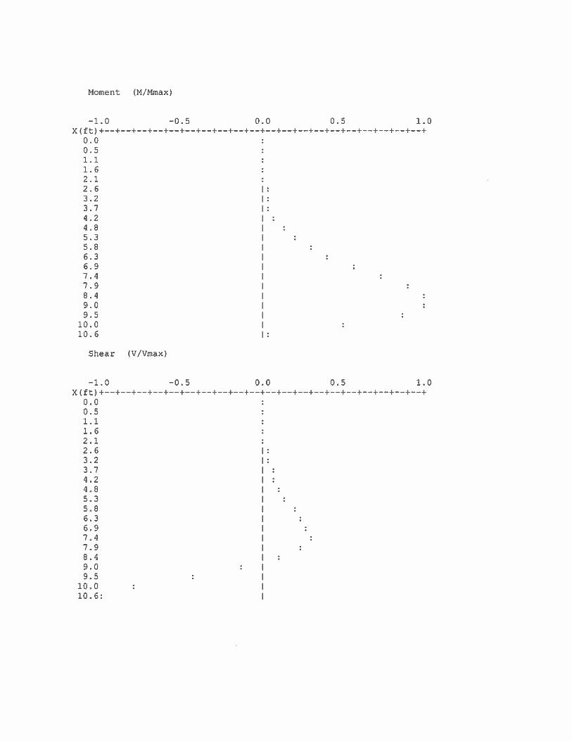
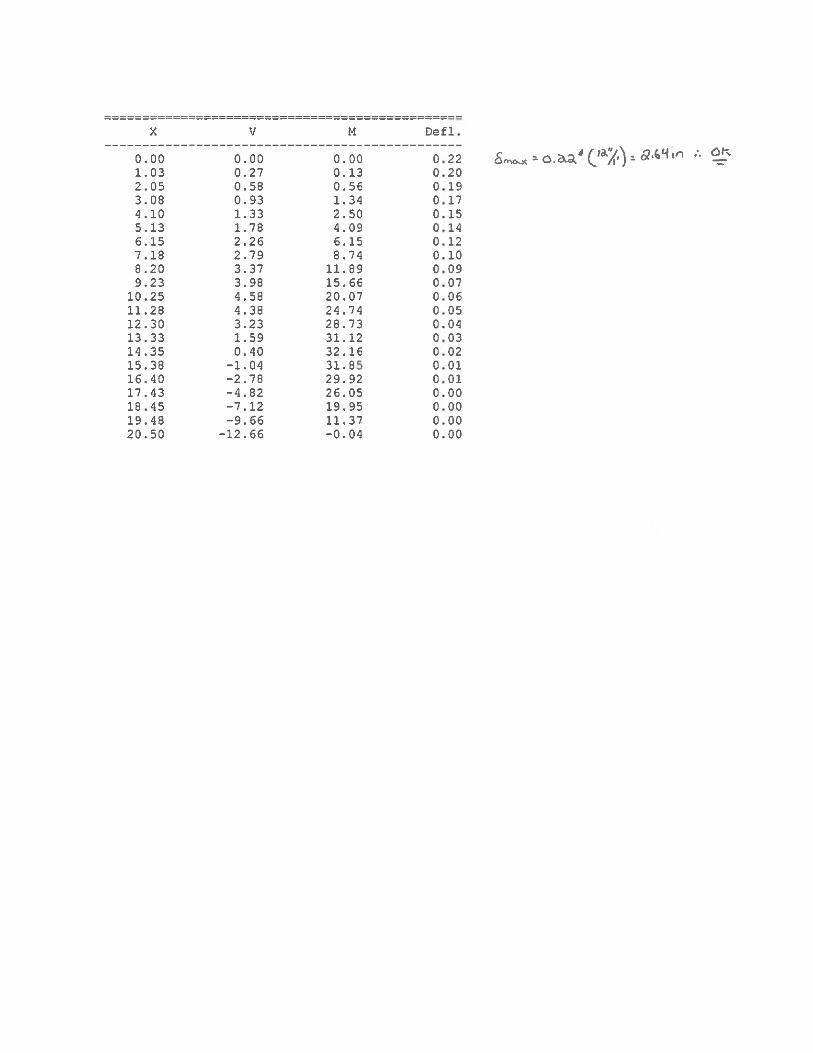
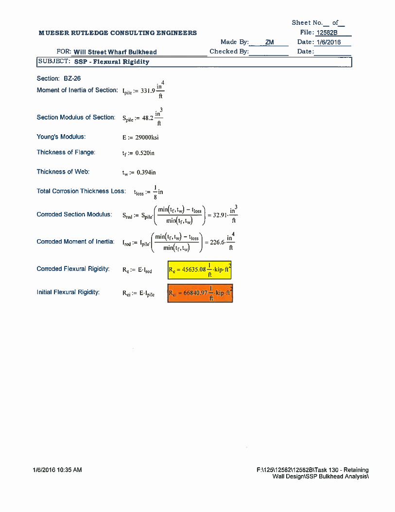
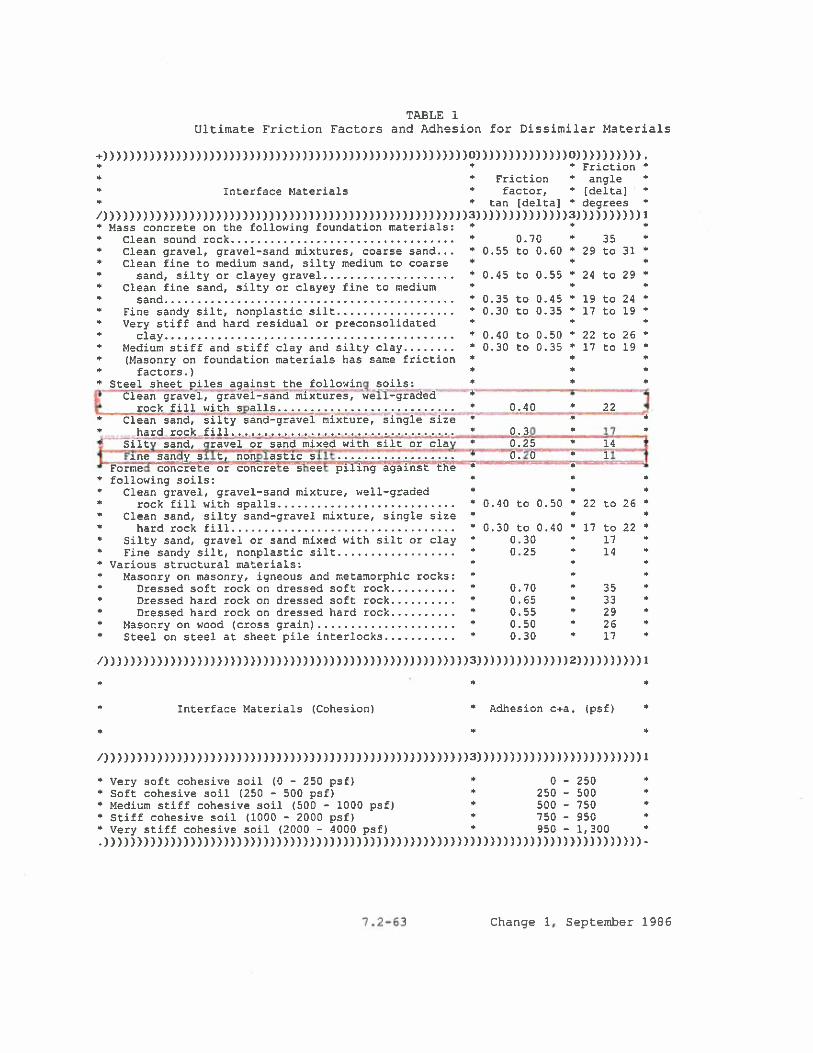
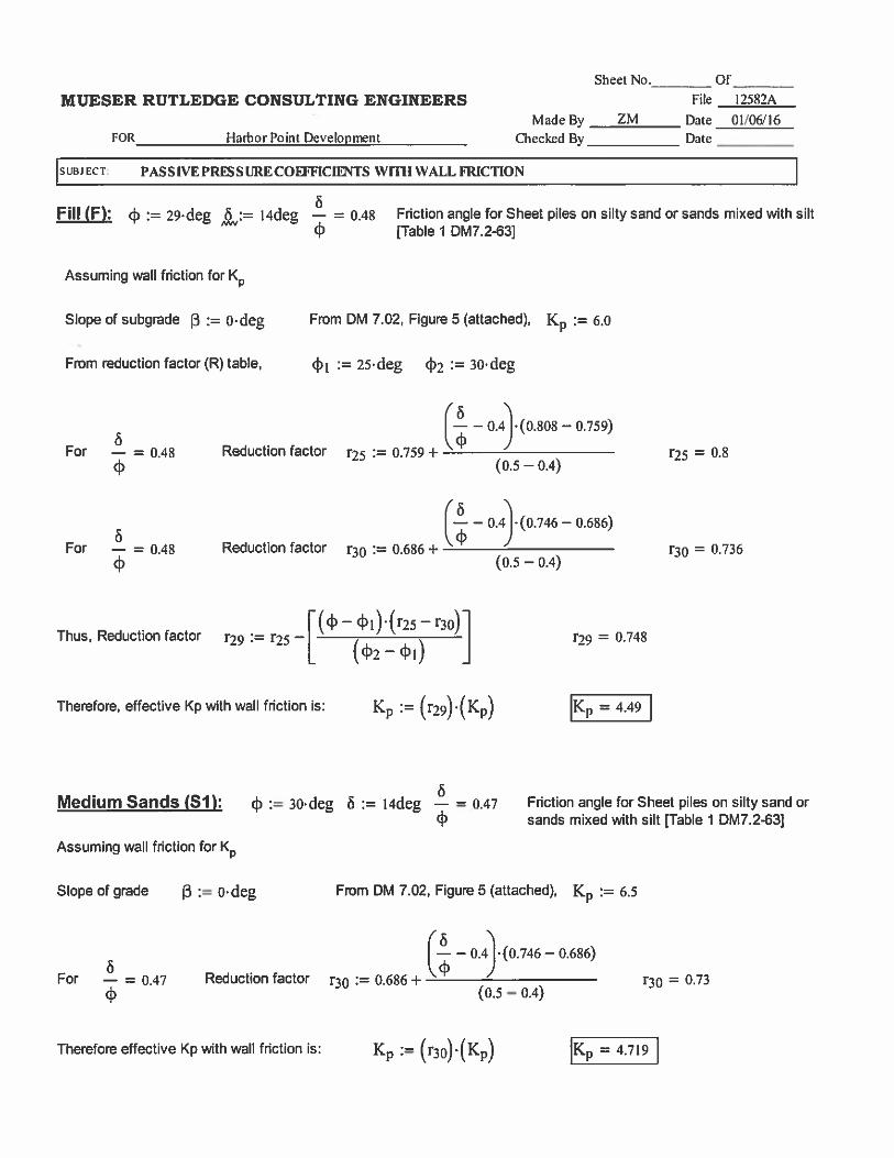
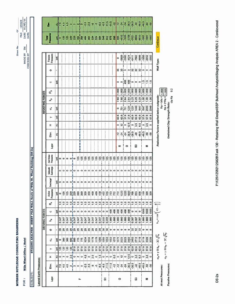
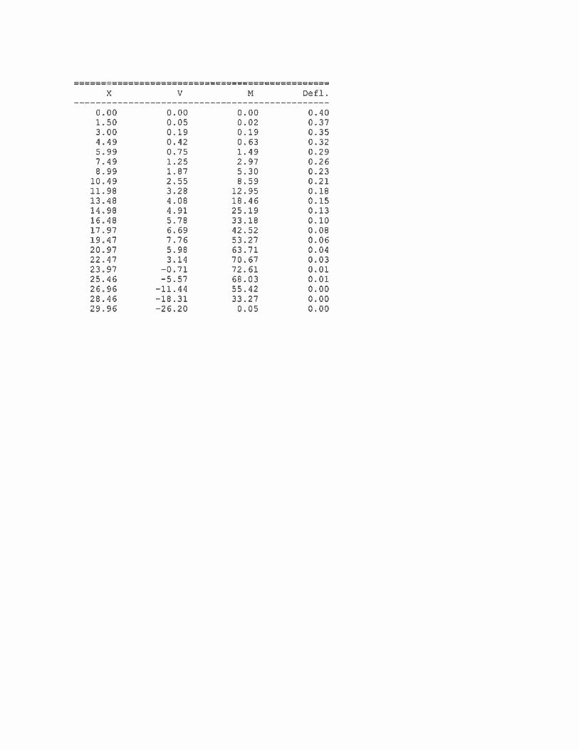
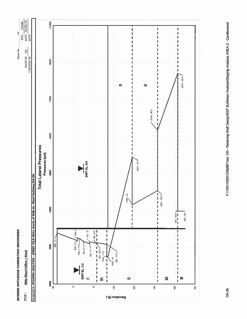
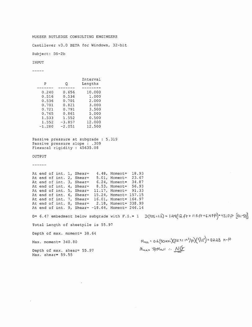
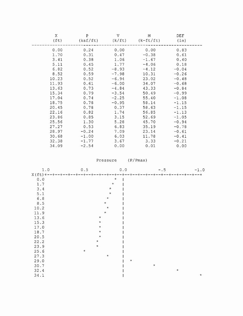
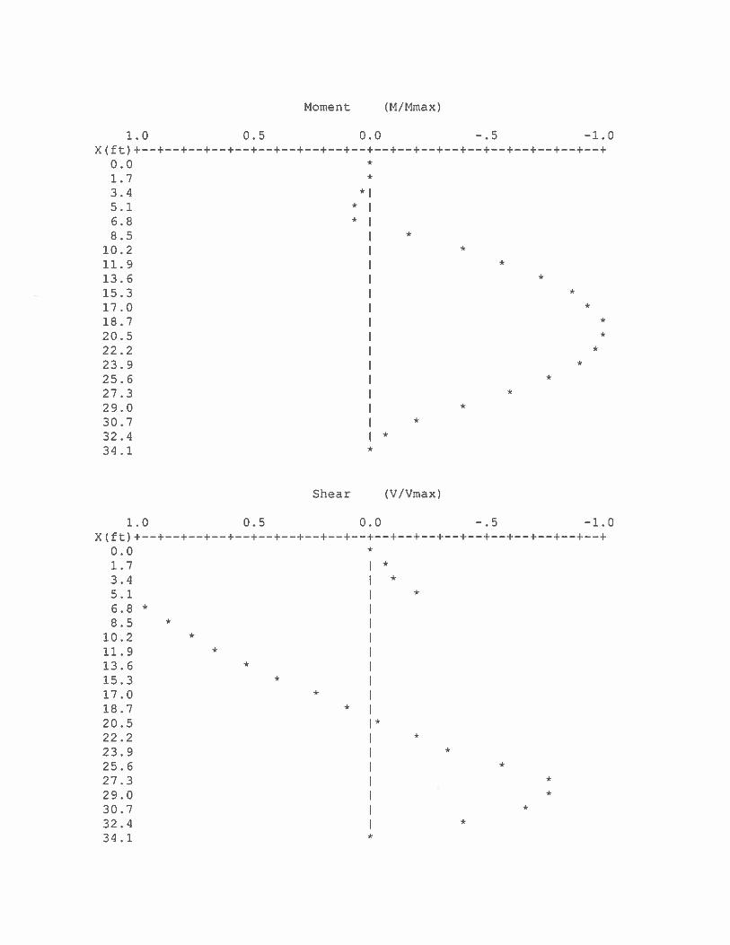
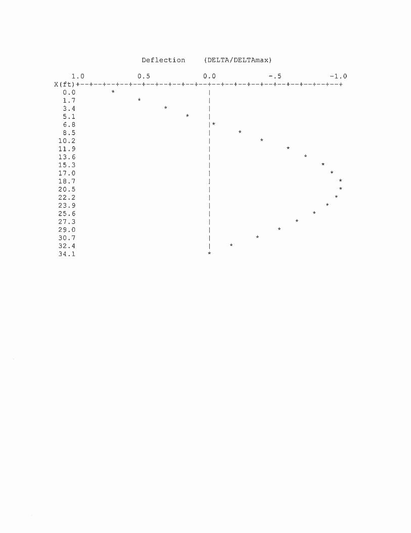
EL. +7.5, sloping upward to EL. +10.0 inboard at a 1:1 slope, with water level at EL. +2.0. South of the sheet pile wall, the top of rip rap is at EL +3.0 and water at EL. 0.0. The existing top of the AZ-13 sheet piles is at EL. +10.0 with a toe at EL. -40.0. This profile is shown on Section B on Drawing F2.02. The western segment of the existing ERS is represented by DS-2a, and runs approximately 118 ft. from the west end of DS-1a, continuing to the west, ending at the proposed centerline of the Wills St. Extension as shown on drawing 1305D. Along this segment, existing grade surface is at EL. +7.5 with water at EL. +2.0 behind the ERS and at EL. 0.0 in front. The top of the BZ-26 steel sheet piles at EL. +7.5 and extend to El. -40.0. South of this segment, the top of rip-rap is at EL. -12.0. This profile is shown on drawing 1305D. Sheet pile has corrosion losses and holes which require repair. Structural analysis considered loses but hole damage has not been accounted for. Proposed Development The proposed new promenade is to be constructed south of the new Wills Wharf Office & Hotel structure, extending over the existing sheet pile wall. This will require the existing grade elevation north of the sheet pile wall to be raised to El. +13.0. The proposed profiles are represented in two segments, by Design Segment 1b (DS-1b), and 2b and 2c (DS-2b & DS-2c). A 600 psf vertical construction surcharge was used in the analysis. Assessment Design Section 1 – AZ 13 Sheet pile Installed Circa 2008 The proposed grade of EL. +13 results in a 10 ft., cantilever flexible wall. The maximum expected deflection, at the top of the wall is approximately 2.6in. The bending stress in the sheet pile is within code allowable stress. For this analysis, a total of 1/8 in. steel thickness loss due to corrosion was assumed in the calculation of AZ-13 sheet pile section properties. The embedment of the sheet pile was adequate to provide the required safety factor. Design Section 2 – BZ-26 Sheetpile Installed Circa 1990: The proposed raised grade north of the sheet pile wall of EL. +13.0 results in a retained height of 25ft. The resulting forces would overstress and de-stabilize the existing BZ-26 sheet pile. Conclusions Design Section 1 Analysis shows that raising the grade from El. +10.0 to El. +13.0 north of the sheet pile wall, will increase the sheet pile deflection to an estimated 2.5 inches. The stresses in the sheet pile would be within allowable and the sheet pile embedment provides an adequate factor of safety. To reduce deflection the sheetpile could be anchored using a shallow concrete deadmen or rip-rap placed south of the sheet pile wall. . Design Section 2 Analysis shows that raising the grade surface elevation from El. +7.5 to El. +13.0 would have a significant adverse impact on the sheet pile wall. To accommodate the proposed grade, the sheet pile wall can anchored at the top of the sheet pile wall using a deadmen system or rip-rap placed south of the wall. Steel sheet repair is needed to prevent soil through holes. F:\125\12582\12582B\Task 130 - Retaining Wall Design\SSP Bulkhead Analysis\EE Memo - Wills Street Bulkhead Wall - 01-2016 -

Exhibits


![Pile Foundation Design[1] - ITDmtp.itd.co.th/ITD-CP/data/PileFoundationDesign.pdf · Introduction to pile foundations Pile foundation design Load on piles Single pile design Pile](https://img.pdfslide.net/doc/110x75/5a6ffb387f8b9ab1538b8376/pile-foundation-design1-itdmtpitdcothitd-cpdatapilefoundationdesignpdfpdf.jpg)


![[04899] - Design of Pile & Pile-Cap](https://img.pdfslide.net/doc/110x75/5695d3331a28ab9b029d273d/04899-design-of-pile-pile-cap.jpg)