Embed Size (px)
Citation preview

Research Project EASA.2011/6
MULCORS - Use of MULticore proCessORs in airborne Systems
easa.europa.eu

Disclaimer
This study has been carried out for the European Aviation Safety Agency by an external organization and expresses the opinion of the organization undertaking the study. It is provided for information purposes only and the views expressed in the study have not been adopted, endorsed or in any way approved by the European Aviation Safety Agency. Consequently it should not be relied upon as a statement, as any form of warranty, representation, undertaking, contractual, or other commitment binding in law upon the European Aviation Safety Agency.
Ownership of all copyright and other intellectual property rights in this material including any documentation, data and technical information, remains vested to the European Aviation Safety Agency. All logo, copyrights, trademarks, and registered trademarks that may be contained within are the property of their respective owners.
Reproduction of this study, in whole or in part, is permitted under the condition that the full body of this Disclaimer remains clearly and visibly affixed at all times with such reproduced part.

MULCORS
EASA
Thales Avionics page 1 Réf. CCC/12/006898 – rev. 07
EASA 2011.C31
“MULCORS” Project.
The Use of MULticore proCessORS in Airborne Systems”
THALES AVIONICS
Dossier ref. CCC/12/006898 – Rev. 07
Authors : Xavier JEAN, Marc GATTI Guy BERTHON, Marc FUMEY
MULCORS
EASA
Thales Avionics page 2 Réf. CCC/12/006898 – rev. 07
REVISIONS
Revision Date Effect on § Description
00 November, 8th
2012 All Draft of the final Report
01 November, 20th
2012 All Creation of the document
02 November, 26th
2012 All Integration EASA remarks, 2012-11-23
Complement chapters regarding Tasks 1 & 2
03 December, 05th
2012 9.3.6.1..3 Adding a chapter regarding the Hypervisor
04 December, 07th
2012 6 & 13 Upgrade list for Chapters Literature Review and
References
05 December, 07th
2012 None Reference number which should the contract
number EASA.2011.C31.
Adding ® & ™
06 December, 08th
2012 All Modification of recommended guidelines
following MULCORS final report presentation
07 December, 16th
2012 All Modification of recommended guidelines
following MULCORS final report presentation
comments

MULCORS
EASA
Thales Avionics page 3 Réf. CCC/12/006898 – rev. 07
1. DISCLAIMER 8
2. ACKNOWLEDGEMENTS 9
3. EXECUTIVE SUMMARY 10
3.1. AIMS / OBJECTIVES 10 3.2. OVERALL APPROACH 10 3.3. EASA EXPECTATIONS 10 3.4. FINDINGS ACHIEVEMENTS AND CONCLUSIONS 11
4. BACKGROUND 12
4.1. DIGITAL EMBEDDED AIRCRAFT SYSTEMS 12 4.2. USE OF COTS PROCESSORS IN EMBEDDED AIRCRAFT EQUIPMENT 12 4.3. USE OF MULTI-CORE IN EMBEDDED AIRCRAFT EQUIPMENT 13
5. AIMS AND OBJECTIVES 14
6. LITERATURE REVIEW 15
6.1. AVIONIC STANDARDS 15 6.2. OFFICIAL GUIDELINES 16 6.3. STUDIES ON PROCESSOR EVALUATION AND SELECTION 16 6.4. STUDIES ON ROBUST PARTITIONING 16 6.5. STUDIES ON WCET CALCULUS 17 6.6. STUDIES ON MULTICORE PROCESSORS SCHEDULING 18 6.7. STUDIES ON HYPERVISORS AND OPERATING SYSTEMS 18 6.8. REFERENCE MANUAL OF STUDIED PROCESSORS 18
7. METHODOLOGY 20
8. IMPLEMENTATION 21
9. RESULTS AND OUTCOME 23
9.1. REQUIREMENTS FOR AN EMBEDDED AIRCRAFT SYSTEMS 23 9.1.1. DETERMINISM IN EMBEDDED AIRCRAFT SYSTEMS 23 9.1.1.1. Embedded Aircraft Systems integrity 23 9.1.1.2. WCET analyzability 25 9.1.1.3. Airborne Embedded System Usage Domain 25 9.1.1.4. Robust Partitioning 26 9.1.2. CERTIFICATION OBJECTIVES FOR EMBEDDED AIRCRAFT SYSTEMS 27 9.1.2.1. Intended Function 28

MULCORS
EASA
Thales Avionics page 4 Réf. CCC/12/006898 – rev. 07
BSP or Board Support Package 29 9.1.2.1..1 Hypervisor 29 9.1.2.1..2 Operating System 30 9.1.2.1..3 Device drivers 31 9.1.2.1..4
9.1.2.2. Safety Objectives 31 9.1.2.3. Foreseeable Conditions 32 9.2. PROCESSORS SELECTION 33 9.2.1. STRATEGIC SELECTION CRITERIA 33 9.2.1.1. Selection criteria regarding the manufacturer situation 33 9.2.1.2. Manufacturer openness regarding design and tests information 34 9.2.2. TECHNICAL SELECTION CRITERIA 34 9.2.2.1. Focus on core architecture 34
Instruction model 34 9.2.2.1..1 Pipeline issues 36 9.2.2.1..2 Virtual memory management 37 9.2.2.1..3 Private caches and scratchpads 38 9.2.2.1..4
9.2.2.2. Focus on peripherals 39 9.2.2.3. Focus on hardware assist for debug and monitoring 40 9.3. MULTI-CORE TECHNOLOGY STATE-OF-THE-ART 41 9.3.1. SUMMARY OF TASK 1 41 9.3.2. SUMMARY OF TASK 2 41 9.3.3. BASIC ARCHITECTURE CHARACTERISTICS 42 9.3.3.1. Memory sharing architecture 43
Unified Memory Access (UMA) 43 9.3.3.1..1 What about caches? 44 9.3.3.1..2 Distributed Architecture (DA) 45 9.3.3.1..3 Architecture named “Single Address space, Distributed Memory” or SADM 46 9.3.3.1..4
9.3.4. MULTI-CORE GALAXY OVERVIEW 47 9.3.4.1. A short overview of processor roadmap 47
Freescale Roadmap 47 9.3.4.1..1 ARM Roadmap 49 9.3.4.1..2 INTEL® ROADMAP 50 9.3.4.1..3
9.3.4.2. Multi-core processors manufacturers and addressed market segments 52 9.3.4.3. Academic projects around multi-core 53 9.3.4.4. Industrial collaborations 54 9.3.5. SOFTWARE SUPPORT FOR EMBEDDED AIRCRAFT SYSTEMS 54 9.3.5.1. Airborne Certified Operating System 54 9.3.5.2. Software definition / explanation 55
Processes and Threads 55 9.3.5.2..1 Multithreading 55 9.3.5.2..2 Processes, kernel threads, user threads 55 9.3.5.2..3
9.3.5.3. The impact of multi-cores on Software Development 56 Memory Management 56 9.3.5.3..1 Mapping 57 9.3.5.3..2
9.3.6. EXAMPLES OF REPRESENTATIVE MULTI-CORE ARCHITECTURES 58 9.3.6.1. Communication and Networking Processor 58
Freescale QorIQ™ P2020 58 9.3.6.1..19.3.6.1..1.1 e500 Coherency Module (ECM) and Address Map 59
e500mc Cores 60 9.3.6.1..2 Hypervisor 62 9.3.6.1..3

MULCORS
EASA
Thales Avionics page 5 Réf. CCC/12/006898 – rev. 07
Networking platform: Freescale QorIQ™ P4080 63 9.3.6.1..49.3.6.1..4.1 QorIQ™ Processor Interconnect 64 9.3.6.1..4.2 Peripherals 64 9.3.6.2. Low-Power Multi-core IP: ARM CORTEX®-A15 MPCore™ 65
CORTEX®-A15 Cores 66 9.3.6.2..1 Snoop Control Unit: First Level interconnect 66 9.3.6.2..2 Corelink™ Network: Peripheral interconnect 67 9.3.6.2..3
9.3.6.3. Multi-core DSP: Texas Instruments TMS320C6678™ 68 DSP Cores: C66x™ CorePac 69 9.3.6.3..1 TMS320C66xx™ interconnect: TeraNet™ 70 9.3.6.3..2
9.3.6.4. SoC FPGA Hard Processor System: Altera Cyclone® V 71 9.4. MULTI-CORE FEATURES REGARDING CERTIFICATION 72 9.4.1. INTRODUCTION 72 9.4.2. PROCESSOR FEATURES IMPACT ON DETERMINISM 73 9.4.2.1. Summary of task 3 73 9.4.2.2. Summary of task 4 73 9.4.2.3. Interconnect 73
Overview 73 9.4.2.3..1 Interconnect Classification criteria 75 9.4.2.3..2 Interconnect Usage Domain 77 9.4.2.3..3
9.4.2.3..3.1 Objective and Definition 77 9.4.2.3..3.2 Related selection criteria 79
Interconnect features regarding multi-core processor integrity 82 9.4.2.3..49.4.2.3..4.1 Integrity of transactions services in the interconnect 82 9.4.2.3..4.2 Related selection criteria 83
Interconnect features regarding Worst Case Execution Time calculus 83 9.4.2.3..59.4.2.3..5.1 Related selection criteria 85
Interconnect features regarding Robust Partitioning insurance 86 9.4.2.3..69.4.2.3..6.1 Related selection criteria 86 9.4.2.4. Shared caches 86
Cache Classification criteria 87 9.4.2.4..1 Content prediction features 88 9.4.2.4..2 Classic cache configurations 89 9.4.2.4..3
9.4.2.4..3.1 Cache partitioning 89 9.4.2.4..3.2 Cache use as SRAM 89
Corresponding selection criteria 90 9.4.2.4..49.4.2.5. Cache coherency mechanisms 91
Corresponding selection criteria 92 9.4.2.5..19.4.2.6. Shared services 93
Shared Services Classification criteria 93 9.4.2.6..1 Corresponding selection criteria 96 9.4.2.6..2
9.4.2.7. Cores 97 Corresponding selection criteria 98 9.4.2.7..1
9.4.2.8. Peripherals 98 Corresponding selection criteria 100 9.4.2.8..1
9.5. SOFTWARE ASPECTS 101 9.5.1. SUMMARY OF TASK 7 101 9.5.2. SUMMARY OF TASK 8 101 9.5.3. AIRBORNE SOFTWARE DEPLOYMENT ON A MULTI-CORE PLATFORM 101 9.5.3.1. Airborne Software execution on several cores 101

MULCORS
EASA
Thales Avionics page 6 Réf. CCC/12/006898 – rev. 07
Multitasks scheduling features 102 9.5.3.1..1 Airborne Software migration from single-core to multi-core platforms 103 9.5.3.1..2 Partitioned system features 104 9.5.3.1..3
9.5.3.1..3.1 Components evolution to take benefit of multi-core platforms 104 9.5.3.1..3.2 Deployment of partitions 105 9.5.3.1..3.3 Symmetrical Multi-processing 105 9.5.3.1..3.4 Asymmetrical Multi-processing 106 9.5.3.1..3.5 AMP-SMP-BMP selection 106 9.5.3.1..3.6 Others deployment schemes 108 9.5.3.2. Airborne Equipment software features 109
Architectural concerns 109 9.5.3.2..19.5.3.2..1.1 Symmetrical Multi Processing 109 9.5.3.2..1.2 Asymmetrical Multi Processing 110 9.5.4. MITIGATION MEANS 111 9.5.4.1. Summary of task 5 111 9.5.4.2. Mitigation Means Analysis 111 9.5.4.3. Time jitter ratio to total execution time 112 9.5.4.4. Airborne Software WCET evaluation 113 9.5.4.5. Monitoring during real-time execution 113 9.5.4.6. Airborne Software robustness 113 9.6. FAILURE MITIGATION MEANS 114 9.6.1. SUMMARY OF TASK 10 114 9.6.2. MITIGATION MEANS 114 9.7. COTS RELATED FEATURES 115 9.7.1. SUMMARY OF TASK 11 115 9.7.2. COTS RELATED FEATURES ANALYSIS 115 9.7.2.1. Electro-migration 116 9.7.2.2. Single Event Effects 116 9.8. METHOD AND TOOLS 118 9.8.1. SUMMARY OF TASK 9 118 9.8.2. METHODS AND TOOLS ANALYSIS 118 9.9. EASA GUIDELINE FOR MULTI-CORE PLATFORMS 121 9.9.1. SUMMARY OF TASK 6 121 9.9.2. PROPOSED GUIDELINE 121
10. OUTREACH 123
11. CONCLUSIONS 124
11.1. CONCLUSIONS WITH RESPECT TO THE REDUCTION OF COMPLEXITY 124 11.2. MULTI-CORE PROCESSOR USAGE DOMAIN RELATED CONCLUSIONS 125 11.3. SIGNIFICANT FEATURES RELATED CONCLUSIONS 125 11.4. CONCLUSIONS ON ROBUST PARTITIONING 125 11.5. CONCLUSIONS ON SUGGESTED MODIFICATION TO EASA GUIDANCE 126 11.5.1. ROUTES TO COMPLIANCE 126 11.5.2. ADVANCED GUIDANCE 126
12. RECOMMENDATIONS 127
MULCORS
EASA
Thales Avionics page 7 Réf. CCC/12/006898 – rev. 07
12.1. PURPOSE 127 12.2. PROCESSOR SELECTION GUIDE 129 12.3. USAGE DOMAIN 132 12.4. CACHE COHERENCY 133 12.5. OPERATING SYSTEM & TASKS ALLOCATIONS 134 12.6. SHARED SERVICES 134 12.7. CORES 135 12.8. PERIPHERALS 135 12.9. FAILURE MITIGATION 135
13. REFERENCES 136
14. APPENDIXES 138
14.1. REVIEW OF EXISTING EASA GUIDANCE IN EASA CM SWCEH-001 ISS. 1 REV. 1 138 14.1.1. REVIEW OF EASA CM SWCEH-001 138 14.1.2. MULTI-CORE ASPECTS ALREADY AVAILABLE IN EASA CM SWCEH-001 ISS. 1 REV. 1 142 14.1.3. STRUCTURING ACTIVITIES 142 14.2. EXAMPLE OF PROCESSOR CLASSIFICATION 145

MULCORS
EASA
Thales Avionics page 8 Réf. CCC/12/006898 – rev. 07
1. DISCLAIMER
This study has been carried out for the European Aviation Safety Agency by an external organization and
expresses the opinion of the organization undertaking the study. It is provided for information purposes
only and the views expressed in the study have not been adopted, endorsed or in any way approved by the
European Aviation Safety Agency. Consequently it should not be relied upon as a statement, as any form
of warranty, representation, undertaking, contractual, or other commitment binding in law upon the
European Aviation Safety Agency.
Ownership of all copyright and other intellectual property rights in this material including any
documentation, data and technical information, remains vested to the European Aviation Safety Agency.
None of the materials provided may be used, reproduced or transmitted, in any form or by any means,
electronic or mechanical, including recording or the use of any information storage and retrieval system,
without express written consent from the European Aviation Safety Agency. All logo, copyrights,
trademarks, and registered trademarks that may be contained within are the property of their respective
owners.
Persons wishing to reproduce in whole or in part the contents of this study are invited to submit a written
request to the following address:
European Aviation Safety Agency (EASA)
Safety Analysis and Research Department
Research Project Manager
Ottoplatz 1
D-50679 Cologne
Germany

MULCORS
EASA
Thales Avionics page 9 Réf. CCC/12/006898 – rev. 07
2. ACKNOWLEDGEMENTS
This report concludes the MULCORS project contracted with EASA. It provides the main outputs,
recommendations and conclusions per EASA Specifications attached to the Invitation to Tender
EASA.2011.OP.30.
Project MULCORS - The Use of MULticore proCessORS in Airborne Systems was organized into a set of
tasks conducted with reference to the required subject and scope of the contract.
Interim reports were produced at dedicated milestones along with the execution of tasks whose results are
further described in the Results and Outcome section 8 of the present report.
Thales would like to thank EASA, both for funding this study project and for its contribution in the reviews
of the tasks performed, and its feedback on interim provided reports.
Thales acknowledges the contribution of Xavier Jean, PHD engineer that provided a high level of expertise
in the technical matters that were necessary to support such a study.
Finally, the authors of this report recognize the quality of the input from all skilled technical experts and
experienced key personnel that were allocated to the project.

MULCORS
EASA
Thales Avionics page 10 Réf. CCC/12/006898 – rev. 07
3. EXECUTIVE SUMMARY
This section summarizes the overall content of this report as a result of MULCORS study.
3.1. AIMS / OBJECTIVES
MULCORS aims and objectives are
To provide a survey of Multi-core processors market availability
To define multi-core processors assessment & selection criteria
To perform investigations on a representative multi-core processor
To identify mitigation means, design and usage rules & limitations
To suggest recommendations for multi-core processor introduction
And to suggest complementary or modification to EASA guidance
3.2. OVERALL APPROACH
To cover this study, EASA and Thales have decided to cut it in 12 steps. Each step paves the road to
analyze how to introduce safely Multi-Core processor in Embedded Aircraft Systems point per point.
The approach taken in conducting this study was a "Top-Down" one, which consisted in starting with a
survey and analysis of the main specific features of a selection of COTS Multi-core Processors, then in
establishing recommendations that can be used by EASA to complement its guidance, and by applicants in
the determination of compliance of COTS Multi-core Processors with certification requirements.
This approach may be compared to another approach, i.e. more bottom-up, that would be more suited for a
developer of a computing unit implementing COTS Multi-core processors. In that context, such an
approach should start with the establishment of requirements specifications for the Airborne Electronic
Hardware (AEH), taking into account design requirements in relationship with the use of a selected COTS
Multi-core processor.
This approach helps to analyze all the stakes for Multi-core Processor introduction in Embedded Aircraft
Systems from Market evolution regarding Hardware and Software up to mitigation to be implemented for
Risk Management.
3.3. EASA EXPECTATIONS
The objective of the study was to provide EASA with sufficient data, analyses and recommendations to
enable EASA to have a better understanding of the state of the art concepts/features related to MCP1 and
their subsequent impact on the compliance demonstration to finally write and publish guidance material on
the subject of the use of multi-core processors in safety-critical airborne systems.
1 MCP : Muti-Core Processor

MULCORS
EASA
Thales Avionics page 11 Réf. CCC/12/006898 – rev. 07
3.4. FINDINGS ACHIEVEMENTS AND CONCLUSIONS
This report contains one section dedicated for recommendations to help building a guideline for COTS
multi-core processor introduction.
From Thales point of View introduction of processor multi-core in Embedded Aircraft Systems can be
considered as inevitable due to the market evolution where single core processors aims to disappear.
Avionics needs to master multi-core processor introduction in certified Embedded Aircraft Systems such as
Displays, IMA systems, Flight Control System, Breaking-Steering System, FADEC, Avionics Server, etc.
To reach this goal, Thales Avionics position is to propose recommendations to complement current EASA
guideline (ED80 / EASA Cert. Memo SWCEH-001 issue: 01, Rev. 1) on (Highly) Complex COTS with the
following additional recommendations for component selection and implementation:
Interconnect analysis allowing defining its Domain Usage.
Interconnect Usage Domain definition:
o This includes the Methodology to ensure the completeness and validation of the Usage
Domain which guarantees the compatibility with current Avionics constraints associated to
the envisioned usage (DAL2) whatever the Airborne System type.
o This is the key point where Airborne System Provider, Certification Applicant and
Certification Authorities have to agree on COTS for acceptability.
Mechanisms to manage Interconnect Usage Domain.
Operating System or Scheduler:
o Tasks or Processes allocation
o Needs for Hypervisor
Cache management.
Core management.
Shared services at COTS device level.
.
2 DAL : Design Assurance Level

MULCORS
EASA
Thales Avionics page 12 Réf. CCC/12/006898 – rev. 07
4. BACKGROUND
4.1. DIGITAL EMBEDDED AIRCRAFT SYSTEMS
Embedded Aircraft Systems are composed of Airborne Software installed on Hardware elements. That
Airborne Software must fulfill the requirements for safety critical functionality on the aircraft.
Thus, the design, development, certification and operation of the software have to meet Reliability,
Availability, Maintainability and Safety (RAMS) objectives depending on their Design Assurance Level
(DAL).
Hardware (HW) and Software (SW) components have followed the evolution of technology over the last
decades, including technological transitions. Yet the confidence in RAMS of the overall system has not
been degraded. Similarly, an equivalent level of safety is expected by Thales from the use of COTS multi-
core technology.
4.2. USE OF COTS PROCESSORS IN EMBEDDED AIRCRAFT EQUIPMENT
One major technological step in the Embedded Aircraft Equipment was the introduction of Commercial
Off The Shelf (COTS) processors in avionics.
COTS processor architectures have become more and more complex from single CORE requiring external
bridge to interconnect Busses and memories (like in the PPC G3 type) up to Micro-Controllers where a
bridge has been embedded in the processor (like in the PPC G4 type) with other features such as network
(Ethernet), video, audio, bus (USB, PCI, PCIe, etc.) and other interfaces.
Use of COTS multi-core processors technology in safety-critical Airborne Software tends to be the
preferred and undisputed choice for the future generation of Airborne Embedded Systems to satisfy
processing performance requirements and weight reduction of digital electronic hardware in avionics.
Those COTS multi-core processors are classified like the current micro-controller ones as Highly Complex
COTS as they feature quite a number of highly integrated execution units and associated control
mechanisms embedded in the device.
In addition, internal architecture may not be directly accessible to the developers implementing such
devices in their design.
COTS Multi-core design data, understood as either ED-80/DO-254-usable life-cycle data, or component’s
in-house development data, is generally not available for review and remains proprietary to the component
manufacturer. Hence difficulties arise when design assurance must be shown and demonstrated.

MULCORS
EASA
Thales Avionics page 13 Réf. CCC/12/006898 – rev. 07
4.3. USE OF MULTI-CORE IN EMBEDDED AIRCRAFT EQUIPMENT
The introduction of COTS multi-core processors in Embedded Aircraft Equipment is motivated by the
following aspects:
Provide a long-term answer to the increasing demand of processing power for the embedded
hardware elements with an acceptable power consumption and weight (reduce environmental
footprint comparing to the current ones).
Anticipate the mass market obsolescence for single-core processors.
o A first step can be to be able to solve single core obsolescence by the replacement of this
single-core by a multi-core with only one active core, others are disabled.
Expected from COTS Multi-core use in Embedded Aircraft Equipment is a combination of three
factors :
o Increased performance,
There is law for predicting the performance ratio regarding the numbers of cores
(Amdhal Law, Gustafson Law) and the number of Threads that can be executed in
parallel
o Increased integration
Less equipment to realize the same functionality or the same amount of equipment to
host more functionality.
o Reduce environmental footprint
Fewer embedded equipment, less power consumption, less dissipation compared to
the single core equivalent.
Be able to “simplify” the use of a Multi-Core Processor thanks to its throughput.
o With, for example, a partitioned architecture, implementing a high DAL level Airborne
Software application on one core exchanging data with a low level Airborne Software
application implemented on an another core. Arbitration can be made to favor the High
DAL level Airborne Software application offering safety for this level.

MULCORS
EASA
Thales Avionics page 14 Réf. CCC/12/006898 – rev. 07
5. AIMS AND OBJECTIVES
The basis for the project was to conduct a study of the multi-core processors that are currently available
and that are anticipated within the next few years, based on public information and roadmap.
The objective of the study was to provide EASA with sufficient data, analyses and recommendations to
enable EASA to write and publish guidance material on the subject of the use of multi-core processors in
safety-critical airborne systems.
The study examined different Hardware (HW) and Software (SW) architectures of multi-core processors to
determine which characteristics of these architectures would enable them to host safety-critical Airborne
Software and which have negative implications in terms of the ability of the systems to host safe, robustly
partitioned and deterministically executed Airborne Software.
We have then reduced the scope to a selection of few candidates representative of various implementations,
which were examined in detail in the study so as to highlight the significant characteristics of the group that
are new or different from those of single core processors, whether the characteristics are favorable or
unfavorable for the use of the type in safety-critical Airborne Software, and whether any mitigation
measures might be used in each case to adapt the type for use in safety-critical Airborne Software.
One purpose of MULCORS was to introduce criteria for multi-core architectures in order to ease their
evaluation by the certification authorities in a certification process.
We further distinguished two classes of evaluation criteria:
Multi-core specific criteria that would be irrelevant in a non-multi-core context
Complex COTS criteria that are relevant both for multi-core and non-multi-core computing
platforms.
Another objective of MULCORS was to use the EASA “Certification Memorandum for Complex
Electronic Hardware (CEH)” recommendations in regard to the multi-core technology. This analysis
should result in a proposition regarding specific recommendations linked to the multi-core context.
The study examined other aspects such as:
Software aspects of using multi-core processors to host safety-critical Airborne Software, including
any Supervisor / Hypervisor and Operating System.
Tools and techniques that may be used to specify the software requirements and the software design
so as to efficiently and safely execute software in parallel on multi-core processors.
Verification and certification implications of hosting software on multi-core processors, including
measuring the Worst Case Execution Time.

MULCORS
EASA
Thales Avionics page 15 Réf. CCC/12/006898 – rev. 07
6. LITERATURE REVIEW
6.1. AVIONIC STANDARDS
SAE ARP 4754: Certification Considerations for Highly-Integrated or Complex Aircraft Systems
Society of Automotive Engineers (SAE), 1996.
This standard addresses problematic that deal with complex embedded systems, included but not
restricted to digital avionics systems
RTCA DO-178B: Software Considerations in Airborne Systems and Equipment Certification.
Radio Technical Commission for Aeronautics (RTCA), 1992.
This standard deals with quality of software conception, development, test and integration.
RTCA DO-178C: Software Considerations in Airborne Systems and Equipment Certification.
Radio Technical Commission for Aeronautics (RTCA), 2012.
This standard is an update of DO-178B
RTCA DO-254 / EUROCAE ED-80: Design Assurance Guidance for Airborne Electronic Hardware.
Radio Technical Commission for Aeronautics (RTCA) and EURopean Organisation for Civil
Aviation Equipment (EUROCAE).
This standard deals with design quality for hardware elements.
RTCA DO-297: Integrated Modular Avionics (IMA) Development, Guidance and Certification
Considerations.
Radio Technical Commission for Aeronautics (RTCA), 2005.
This is the latest standard for IMA systems development and exploitation. It deals with high-level
requirements, Robust Partitioning, Verification and Validation, reuse of components.
EASA CM - SWCEH – 001, issue 1: Development Assurance of Airborne Electronic Hardware,
August 2011
This certification memorandum has been developed by EASA to highlight issues that shall be
addressed in the certification process.
http://www.easa.europa.eu/certification/docs/certification-memorandum/EASA%20CM-SWCEH-
001%20Development%20Assurance%20of%20Airborne%20Electronic%20Hardware.pdf
EASA CS-25: Certification Specifications and Acceptable Means of Compliance for Large Aeroplanes,
Amendment 12 – subpart F, July 2012
http://www.easa.europa.eu/agency-measures/docs/certification-specifications/CS-25/CS-
25%20Amdt%2012.pdf

MULCORS
EASA
Thales Avionics page 16 Réf. CCC/12/006898 – rev. 07
6.2. OFFICIAL GUIDELINES
ARINC-653 P1 revision 3: Avionics Application Software Standard Interface.
Aeronautical Radio Inc, 2010.
This guideline deals with partitions definition and scheduling, Operating System architecture and the
Application Executive interface (APEX) that is a standardized API for the embedded partitions.
ARINC-651: Design Guidance for Integrated Modular Avionics.
Aeronautical Radio Inc, 1991.
This guideline addresses software and hardware concerns in the previous generation of IMA.
6.3. STUDIES ON PROCESSOR EVALUATION AND SELECTION
Forsberg, H. & Karlsson, K. COTS CPU Selection Guidelines for Safety-Critical Applications
25th Digital Avionics Systems Conference, IEEE/AIAA, 2006, 1-12
http://dx.doi.org/10.1109/DASC.2006.313701
Bob, G.; Joseph, M.; Brian, P.; Kirk, L.; Spencer, R.; Nikhil, G.; Daniel, O.; Jason, D. L.; John, S.;
Arnold, N.; Bob, M. & Dr. Rabi, M.
Handbook For The Selection And Evaluation Of Microprocessors For Airborne Systems
Federal Aviation Administration - U.S. Department of Transportation, 2011
http://www.faa.gov/aircraft/air_cert/design_approvals/air_software/media/AR_11_2.pdf
Faubladier, F. & Rambaud, D. Soc Survey Report - Safety Implications of the use of system-on-chip
(SoC) on commercial of-the-shelf (COTS) devices in airborne critical applications
EASA – study ref. EASA.2008.OP.04, 2008
http://www.easa.europa.eu/safety-and-research/research-projects/docs/large-
aeroplanes/Final_Report_EASA.2008_1.pdf
Kinnan, L.M. Use of multi-core processors in avionics systems and its potential impact on
implementation and certification.
28th Digital Avionics Systems Conference, IEEE/AIAA, 2009, pp. 1.E.4.1 – 1.E.4-6
http://dx.doi.org/10.1109/DASC.2009.5347560
6.4. STUDIES ON ROBUST PARTITIONING
Rushby John, Partitioning in Avionics Architectures: Requirements, Mechanisms, and Assurance.
1999
FAA-AR-99/58, Office of Aviation Research, Washington DC
http://www.tc.faa.gov/its/worldpac/techrpt/ar99-58.pdf

MULCORS
EASA
Thales Avionics page 17 Réf. CCC/12/006898 – rev. 07
Wilding Matthew M., David S. Hardin, David A. Greve, Invariant Performance: A statement of Task
Isolation Useful for Embedded Application Integration. 1999
Proceedings of the conference on Dependable Computing for Critical Applications
http://dl.acm.org/citation.cfm?id=555298.789914
Littlefield-Lawwill, J. & Kinnan, L., System considerations for robust time and space partitioning in
Integrated Modular Avionics. 2008
27th Digital Avionics Systems Conference, IEEE/AIAA, 2008
http://dx.doi.org/10.1109/DASC.2008.4702751
6.5. STUDIES ON WCET CALCULUS
Wilhelm, R.; Engblom, J.; Ermedahl, A.; Holsti, N.; Thesing, S.; Whalley, D.; Bernat, G.; Ferdinand,
C.; Heckmann, R.; Mitra, T.; Mueller, F.; Puaut, I.; Puschner, P.; Staschulat, J. & Stenström, P.
The worst-case execution-time problem overview of methods and survey of tools, 2008
ACM Trans. Embed. Comput. Syst., ACM, 2008, 7, 36:1-36:53
http://www.cs.fsu.edu/~whalley/papers/tecs07.pdf
Hardy, D. Analyse pire cas pour processeur multi-cœurs disposant de caches partagés (link in
French) , 2010
PhD Thesis, Université Rennes 1
http://tel.archives-ouvertes.fr/docs/00/55/70/58/PDF/Hardy20101209_phd.pdf
Nowotsch, J. & Paulitsch, M., Leveraging Multi-core Computing Architectures in Avionics, 2012
European Dependable Computing Conference, IEEE Computer Society, 2012, 0, 132-143
http://doi.ieeecomputersociety.org/10.1109/EDCC.2012.27
Pellizzoni, R. & Caccamo, M. Impact of Peripheral-Processor Interference on WCET Analysis of
Real-Time Embedded Systems, 2010
IEEE Trans. Comput., IEEE Computer Society, 2010, 59, 400-415
http://dx.doi.org/10.1109/TC.2009.156
Moscibroda, T. & Mutlu, O. Memory performance attacks: denial of memory service in multi-core
systems, 2007
Proceedings of 16th USENIX Security Symposium on USENIX Security Symposium, USENIX
Association, 2007, 18:1-18:18
http://dl.acm.org/citation.cfm?id=1362903.1362921

MULCORS
EASA
Thales Avionics page 18 Réf. CCC/12/006898 – rev. 07
6.6. STUDIES ON MULTICORE PROCESSORS SCHEDULING
Davis, R. & Burns, A. A Survey of Hard Real-Time Scheduling Algorithms and Schedulability
Analysis Techniques for Multiprocessor Systems, 2009
ACM Comput. Surv., ACM, 2011, 43, 35:1-35:44
http://doi.acm.org/10.1145/1978802.1978814
6.7. STUDIES ON HYPERVISORS AND OPERATING SYSTEMS
Krodel, J. & Romanski, G. Handbook for Real-Time Operating Systems Integration and Component
Integration Considerations in Integrated Modular Avionics Systems, 2008
Federal Aviation Administration - U.S. Department of Transportation, 2008
http://www.tc.faa.gov/its/worldpac/techrpt/ar0748.pdf
Gu, Z. & Zhao, Q. A State-of-the-Art Survey on Real-Time Issues in Embedded Systems
Virtualization, 2012
Journal of Software Engineering and Applications, 2012, 05, 277 – 291
http://dx.doi.org/10.4236/jsea.2012.54033
6.8. REFERENCE MANUAL OF STUDIED PROCESSORS
Freescale Embedded Hypervisor Software User Manual
http://www.freescale.com/infocenter/index.jsp?topic=%2FQORIQSDK%2F1331445.html
Freescale Semiconductor Inc, P4080 QorIQ Integrated Multicore Communication Processor Family
Reference Manual, 01/2012 - Revision. 1
http://www.freescale.com/webapp/sps/site/prod_summary.jsp?code=P4080
(a free account must be created to download the reference manual)
Freescale Semiconductor Inc, EREF 2.0: A Programmer’s Reference Manual for Freescale Power
Architecture® Processors, 09/2011 – Revision 0
http://cache.freescale.com/files/32bit/doc/ref_manual/EREF_RM.pdf
Freescale Semiconductor Inc, e500mc Core Reference Manual, 03/2012 – Revision 1
http://cache.freescale.com/files/32bit/doc/ref_manual/E500MCRM.pdf
ARM, Cortex™-A15 MPCore™ Technical Reference Manual Revision: r3p2, 07/2012
http://infocenter.arm.com/help/topic/com.arm.doc.ddi0438g/DDI0438G_cortex_a15_r3p2_trm.pdf
ARM, CoreLink™ CCI-400 Cache Coherent Interconnect Technical Reference Manual, 11/2012
http://infocenter.arm.com/help/topic/com.arm.doc.ddi0470g/DDI0470G_cci400_r1p1_trm.pdf

MULCORS
EASA
Thales Avionics page 19 Réf. CCC/12/006898 – rev. 07
ARM, ARM Architecture Reference Manual ARMv7-A and ARMv7-R edition, 2012
http://infocenter.arm.com/help/index.jsp?topic=/com.arm.doc.subset.architecture.reference/index.html
(an account must be created to access this document)
Texas Instruments, TMS320C6678™ - Multicore Fixed and Floating-Point Digital Signal Processor,
02/2012
http://www.ti.com/lit/ds/sprs691c/sprs691c.pdf
Texas Instruments, TMS320C66x™ DSP CorePac User Guide, 07/2011
http://www.ti.com/lit/ug/sprugw0b/sprugw0b.pdf
MULCORS
EASA
Thales Avionics page 20 Réf. CCC/12/006898 – rev. 07
7. METHODOLOGY
Besides the organization in tasks described in section 8 below, this study was organized as follows:
1. A preliminary phase which was divided in two part
o The first part where we have defined some requirements applicable to multi-core computing
platforms in an avionic context. Those requirements depend on the different kinds of digital
systems and their level of criticality.
o The second part that deals with processors selection for avionic usage out of the field of
multicore architecture. Two kinds of selection criteria were explored: strategic criteria that
deal with manufacturer selection rather than the processor itself, and technical criteria that
focus on specific points of the architecture. Those criteria are still valid in a multicore
context.
2. A first phase was prospective: we provided a snapshot of the multi-core technology and basic non-
technical criteria for processors early selection. Then we presented some representative multi-core
computing platforms in a more detailed description.
3. A second phase of the study refined multi-core features on the hardware and software aspects. We
illustrate those features on two selected computing platforms. We provided a set of guidelines and
technical selection criteria.
4. A third phase where we deduced from the previous phases additional recommendations for
certification procedures.

MULCORS
EASA
Thales Avionics page 21 Réf. CCC/12/006898 – rev. 07
8. IMPLEMENTATION
The work relevant for this study has been implemented, based on different activities organized in tasks, and
deployed in a logical manner. A summary of those tasks and their arrangement is provided below to allow
a better and easier reference of the results and outcomes exposed in section 8 of this present report.
Task 1. Provide a survey of Multi-core processors market availability
Task 2. Characterize essential multi-core processors types features
Task 3. Define multi-core processors assessment & selection criteria
Task 4. Perform investigations on a representative multi-core processor
Task 5. Identify mitigation means, design and usage rules & limitations
Task 6. Suggest complementary or modification to EASA guidance
Task 7. Investigate operating system software execution related aspects
Task 8. Identify methods, tools, languages and Operating Systems for design
Task 9. Identify methods, tools, means and instrumentation for testing
Task 10. Examine failure detection and recovery mechanisms features
Task 11. Analyze COTS-related features (Errata sheets, SEU, Service experience)
Task 12. Summary conclusion, main results & recommendations and final report
The task flow execution followed the logic in Figure 1 above with the exception of task 7 that needed to be
anticipated earlier than scheduled in the original plan.
A lesson learned from such an organization for a similar project is to limit the breakdown into tasks to less
than a few (around 6 tasks) in order to avoid dispersion of issues over too many packages.
Monthly progress reports were provided and presented to EASA. This led to few amendments to the
original content both programmatic and technical. Also worth to mention is that interim reports were
provided and amended along with each monthly progress reports. This was useful to help reorient the
research to actual EASA needs and directions.
A task summary is provided for reference along with the details discussion in the Results and Outcome
section 8.

MULCORS
EASA
Thales Avionics page 22 Réf. CCC/12/006898 – rev. 07
Architecture – Characteristics
Drawback – Limitations
Task1
Task2
Task3
Task4
Software Architecture – Issues
Task8
Task7
Task9
Failure Mitigation –
Work around
Task5
Task10
Task11
Support for Guidance –
Evolutions – Recommendations
Task6
Task12
All
Architecture – Characteristics
Drawback – Limitations
Task1
Task2
Task3
Task4
Architecture – Characteristics
Drawback – Limitations
Task1Task1
Task2Task2
Task3Task3
Task4Task4
Software Architecture – Issues
Task8
Task7
Task9
Software Architecture – IssuesSoftware Architecture – Issues
Task8Task8
Task7Task7
Task9Task9
Failure Mitigation –
Work around
Task5
Task10
Task11
Failure Mitigation –
Work around
Task5Task5
Task10Task10
Task11Task11
Support for Guidance –
Evolutions – Recommendations
Task6
Task12
Support for Guidance –
Evolutions – Recommendations
Support for Guidance –
Evolutions – Recommendations
Task6Task6
Task12Task12
AllAll
Figure 1: Task Work Flow

MULCORS
EASA
Thales Avionics page 23 Réf. CCC/12/006898 – rev. 07
9. RESULTS AND OUTCOME
9.1. REQUIREMENTS FOR AN EMBEDDED AIRCRAFT SYSTEMS
9.1.1. Determinism in Embedded Aircraft Systems
Determinism is an abstract notion that usually references several high level requirements; part of it is
described in the DO-297 as “The ability to produce a predictable outcome generally based on the preceding
operations, the outcome occurs in a specified period of time with some degree of repeatability”.
Depending on the context, its embodiment may vary. Yet in a general case, we can say that a system is
deterministic as soon as its behavior is ruled by a set of identified laws. Those laws have to be compatible
with certification objectives.
For instance, a device whose response time follows a Gaussian law where means and variance are defined
may not comply with the usual requirements, such as a finite response time.
In this report, we state that an Embedded Aircraft System is deterministic if it fulfills the following
definitions for “Embedded Aircraft System Determinism”:
It is possible to ensure the Execution Integrity of its Airborne Software. That means correct
Airborne Software will be correctly executed in a nominal situation, and the Embedded Aircraft
System state will be predictable in non-nominal situations (internal faults). It does not cover the
case of faulty airborne software.
It is possible to perform a WCET analysis (Worst Case Execution Time) of the embedded software
(Airborne Software and Embedded Aircraft System software). Timing information on the
Embedded Aircraft System behavior (e.g. memory access worst case response time) may be
necessary.
When the Embedded Aircraft System provider has no visibility into, or limited constraints enforced
towards the embedded Airborne Software(s), he shall define a Platform Usage Domain that details
restrictions on the Airborne Software development.
When the Embedded Aircraft System is destined to host a partitioned system, such as in IMA3, the
Embedded Aircraft System provider shall also ensure Robust Partitioning between the hosted
partitions.
9.1.1.1. Embedded Aircraft Systems integrity
To ensure the execution integrity of embedded software, the Embedded Aircraft System provider must
demonstrate that the Embedded Aircraft System mode during non-faulty software execution remains
nominal or degraded into an acceptable state.
3 IMA : Integrated Modular Avionic

MULCORS
EASA
Thales Avionics page 24 Réf. CCC/12/006898 – rev. 07
To obtain this guarantee with an adequate level of confidence (according to the Design Assurance Level),
the Embedded Aircraft System provider must accumulate sufficient knowledge on the processor’s internal
mechanisms.
Such knowledge can be obtained through datasheets, reference manuals, under dedicated NDA4,
Communications, White Papers, Application notes, Errata sheets, laboratory test campaigns, etc.
The growing complexity of COTS processor architecture makes a fine grain description of all internal
features not accessible for Human, Technical and IP5 reasons.
Thus the properties of some features can be partially masked as long as the COTS processor manufacturer
is able to provide guarantees on their observable behavior.
The main difficulties in ensuring Embedded Aircraft System integrity deal with the determination of its
behavior upon the occurrence of internal faults and failures. Therefore, depending on the DAL (Design
Assurance Level), a more or less accurate model of faults has to be defined. Identified faults and failures
shall be mitigated or confined inside the Embedded Aircraft System using dedicated Hardware and/or
Software mechanisms.
As detailed in part 9.4.2.3..4, Embedded Aircraft System integrity in multi-core platforms is closely linked
to a correct transaction service in the interconnect. Here “correct” means that there is neither corruption nor
any silent loss of transactions.
Note: The behavior of the interconnect between cores, memory and shared resources has to be known by
design, by experimental test or by other means and present as a proof to reach acceptance of this
component.
Even if cores and peripherals architecture have been inherited from an existing single-core processor, the
current multi-core generation has introduced an important technological step mainly linked to the
interconnect design.
Note: in most multi-core architectures, from Dual Core like in the P2020 (from Freescale), up to an octo-
core like in the P4080 (from Freescale) or a quad-core like in the ARM_CORTEX®_A15, the interconnect
is the key point where all the accesses are performed. A chapter is dedicated to Interconnect Management.
Indeed, the interconnect has been built to sustain a higher bandwidth in order to serve efficiently all cores.
They enable a high level of pipelining and parallelism in transaction services.
This growing complexity makes the set of all interconnect states highly difficult to determine and analyze -
even with full information on the design (full information is not available even under dedicated NDA
linked to manufacturer IP Policy).
4 NDA : Non Disclosure Agreement
5 IP : Intellectual Property

MULCORS
EASA
Thales Avionics page 25 Réf. CCC/12/006898 – rev. 07
Thus, it may be difficult to obtain guarantees of correct transaction services in a general case. There are
several approaches aimed at preventing inter-core conflicts with dedicated mechanisms, or limiting the
interconnect load in order to remain in a “safe” mode. We plan to describe some approaches in the
Interconnect Management Chapter.
9.1.1.2. WCET analyzability
Worst Case Execution Time analyses aim at determining an upper bound for a piece of software’s
execution time. Usually, the result of a WCET analysis is an upper approximation of the exact WCET
which is nearly impossible to determine for real life Software.
Simple architectures allow WCET determination using static analysis techniques using an execution model
of the Airborne Embedded System. That means the analyzed software is not executed. Yet on complex
COTS processors architectures, it is not possible to determine an accurate enough model. Today, an
alternative method is used. A worst case scenario is defined from an analysis performed on the Airborne
Software. The execution time is measured under this scenario, and is further corrected with parameters
taking into account variable jitters and variability in the duration Airborne Embedded System operations.
When the Airborne Embedded System provider has no visibility into the deployed Airborne Software - for
instance in an IMA -, he shall determine and provide such parameters to the Airborne Software suppliers
and eventually to the Module Integrator.
The lack of information on the processor behavior may lead to pessimistic estimation of those parameters
and degrade the approximation of the WCET.
For instance uncertainty on the cache content must lead to consideration of cache miss situations in the
WCET analysis.
As detailed in part 9.4.2.3..5, the use of multi-core processors in Embedded Aircraft Systems worsens the
WCET analyses. Indeed, the execution time of software on one core depends on software executed on the
other cores because of potential inter-core conflicts. Moreover, it may be difficult to determine an upper
bound on their impact whatever the concurrent software.
9.1.1.3. Airborne Embedded System Usage Domain
When the Airborne Embedded System provider has little or no visibility into the deployed Airborne
Software, he has to define what we call an “Airborne Embedded System Usage Domain” and provide it to
the Airborne Software suppliers.
This Airborne Embedded System Usage Domain details usage limitations that shall be taken into account
during Airborne Software development and execution.

MULCORS
EASA
Thales Avionics page 26 Réf. CCC/12/006898 – rev. 07
Respecting the usage domain is a mandatory and key requirement. Dedicated tools may be used to
automatically perform checks on the usage domain aspect. Moreover, protection mechanisms can be
enforced to prevent usage domain violations that impact robust partitioning.
For instance, assembly instructions can be forbidden when their use impacts the integrity of the Airborne
Embedded System. Various protection means can be highlighted:
A privilege level restriction, which blocks the execution of the instruction
A processor configuration that disables this instruction
A mandatory integration test that checks the absence of such instructions
A trusted piece of software that checks at runtime the absence of such instructions
Yet it shall be proven that in spite of such protections, no failure mode can lead to the execution of a
forbidden instruction.
In the case of multi-Airborne Software systems, the Airborne Embedded Equipment usage domain is
divided into two categories:
Some restrictions deal with Airborne Software development and are destined for the Airborne
Software Suppliers.
Other limitations address the integration of Airborne Software and have to be handled by the
Module Integrator.
The use of multi-core processors is likely to entail changes in the Airborne Embedded System usage
domains. Indeed, the presence of true parallelism between pieces of software (intra and/or inter-partitions
in partitioned systems) adds new parameters that rule software deployment on the different cores.
We can illustrate examples of what could be these rules depending on the processor, the selected Operating
System, the hypervisor (when required);
Inside an Airborne Software installation, multiple critical sections cannot be accessed in parallel by
different cores. Indeed, this situation might lead to deadlocks.
Execution of processes inside a multi-core partition will be pre-allocated on the concerned cores
(rather than dynamically allocated by the scheduler).
In case determinism and/or robust partitioning cannot be absolutely demonstrated, it could be stated
that a DAL-A partition is not allowed to be executed in parallel with other partitions
Note: In a low complex multi-core processor for example in a Dual-Core processor, this Usage Domain
can be more easily demonstrated if Airborne Software is known and managed to match with safety
requirements. When the Airborne Software is unknown, the Airborne Embedded Equipment usage Domain
has to be defined as described above.
9.1.1.4. Robust Partitioning
Robust Partitioning is defined in various formulations in ARP4754, DO 297, ARINC 651 and ARINC 653.
This is a property of fault containment. The reference study (Rushby, 1999) on robust partitioning was
done by John Rushby for the FAA in 2000.
MULCORS
EASA
Thales Avionics page 27 Réf. CCC/12/006898 – rev. 07
Robust partitioning is a mandatory requirement for partitioned Airborne Embedded Systems:
The reference definition for robust partitioning is named the Gold Standard:
“A partitioned system should provide fault containment equivalent to an idealized system in which each
partition is allocated an independent processor and associated peripheral and all inter-partition
communications are carried on dedicated lines”
Yet this general definition requires an accurate model of faults for Airborne Software. To the best of our
knowledge, no direct proof of robust partitioning has been performed today. In practice, it is preferred the
following stronger property, named the Alternative Gold Standard (introduced by David Hardin, Dave
Greve and Matt Wilding):
“The behavior and performance of software in one partition must be unaffected by software in other
partitions”
In IMA systems, an ARINC 653 Time and Space partitioning implementation ensures the Alternative Gold
Standard.
Usually, robust partitioning is ensured through an analysis of interference channels. In multi-core systems,
the possible presence of inter-core conflicts may introduce new channels. Two sub-problems occur:
Is it possible to get rid of those channels?
If no, will interference actually occur through those channels?
This problem is refined in part 9.4.2.3..6.
We have to notice that the property of Robust partitioning is not confined to IMA systems, as we have to
deal with such requirements even in the first step of multi-core processor architectures like in a dual-core
one or when Airborne Software applications of different DALs are executed by the different cores.
Robust partitioning can be ensured
By a hardware mechanism if this mechanism exists in the processor, if it is described and accessible
under dedicated privilege (Supervisor or Hypervisor mode),
By the Operating System allocating priority to the Airborne Software with the highest level of DAL
(DAL-A for example) when Airborne Software of different DAL levels is executed in the Airborne
Embedded System.
Or directly by the Airborne Software at Airborne Embedded System level. At this level, it can be
done only if we can master the temporal execution of each Airborne Software application and solve
the conflicts at this level (threads of processes allocation and description).
9.1.2. Certification objectives for Embedded Aircraft Systems
When taking into account the general certification requirements, the Airborne Embedded System provider
must address the following objectives:

MULCORS
EASA
Thales Avionics page 28 Réf. CCC/12/006898 – rev. 07
PROCESSOR
ARM FREESCALE IBM INTEL TEXAS
PROCESSOR BSP
ARM
BSP
FREESCALE
BSP
IBM
BSP
INTEL
BSP
TEXAS
BSP
HYPERVISOR
ARM
based
FREESCALE
based
IBM
based
INTEL
based
TEXAS
Based
Operating SYSTEM
VxWorks PikeOS LynxOS Integrity MACS2
DRIVERS
Network SOC
Peripherals
Memory /
Flash
I/O
Drivers USB / PCI
AIRBORNE SOFTWARE
Time Critical
Application Utilities Avionics Server IFE
Ensure Intended Function,
Meet Safety Objectives,
Sustain Foreseeable Conditions.
Note that this chapter does not replace applicable requirements such as S/HW compliance with
XX.1301/XX.1309, i.e. development assurance as defined by ED-12B/DO-178B and ED-80/DO-254.
This chapter and this report focus on multi-core processor where ED-12B/DO-178B for embedded micro-
code and/or ED-80/DO-254 for processor Hardware development are not used by processor manufacturer.
At equipment level and/or board level, Airborne Embedded System providers and/or Airborne Software
providers have to be compliant with ED-80/DO-254 and ED-12/DO-178 (B or C) and implement
mitigation to demonstrate the global compliance with ED-80/DO-254 and/or DO-178 with such
components as processors.
9.1.2.1. Intended Function
The functionalities of a processor,
whether it is COTS Mono-Core
or Multi-Core, are always
exercised using:
First a layer of Hardware -
Software interface known
as the processor BSP6,
When required, a
Hypervisor layer
Then the Operating
System itself,
All the required drivers
and Processor drivers
And the last one the
Airborne Software layer
(which is out of the scope of this purpose).
6 BSP : Board Support Package

MULCORS
EASA
Thales Avionics page 29 Réf. CCC/12/006898 – rev. 07
BSP or Board Support Package 9.1.2.1..1
A software layer that adapts the Operating System to the dedicated processors. This layer gives accesses to
the internal resources of the multi-core component but the management of these resources has to be done
by the Hypervisor when required or by the Operating System.
BSP development has to fulfill ED-12/DO-178 (B or C) requirements.
BSP_Remark1: When a Hypervisor is not required, privileged access has to be given in Supervisor
or Hypervisor mode to the Operating System to allow programming of shared resources like
hardware accelerators, arbiters, in order to fulfill safety requirements such as determinism.
BSP_Remark2: if two Operating Systems are used, for example, on a dual-core processor, one of
these two Operating Systems has to be set in the Supervisor or Hypervisor mode to have the
privilege to access to programming of shared resources, the second one has to be set respectively in
User or Supervisor mode.
Hypervisor 9.1.2.1..2
A software layer that acts as a Virtual Machine Monitor. This software layer emulates virtual environments
in which several Operating Systems may be executed simultaneously. In such a configuration, its use may
help mastering the processor behavior regarding dedicated requirements like determinism or conflict
management in shared resources accesses.
We consider, in this report that the Hypervisor level is realize in a SMP mode managing all cores.
RGL n°1
When an Hypervisor is required to manage the behavior of the interconnect, the development of such a
Hypervisor shall fulfill ED-12/DO-178 (B or C) requirements at the corresponding Design Assurance
Level, at least the most stringent Airborne Software.
HYP_Remark1: we see that there is a relationship between the intended function and objectives
with respect to safety and foreseeable conditions, as, at least for functional operation, the influence
of external Airborne Software input authority is limited by such a hypervisor, while the latter is
providing the deterministic behavior, performance characteristics and integrity necessary to the end-
user Airborne Software.
The use of a Hypervisor layer is not mandatory, for example in a dual core processor, where the behavior
of this dual-core processor can be managed directly at the Airborne Software level.
Let us detail this:
We are able to master the complete behavior of Airborne Software application(s) running on the
processor even in SMP mode (during any one period of time, the multi-core processor is allocated

MULCORS
EASA
Thales Avionics page 30 Réf. CCC/12/006898 – rev. 07
to only one Airborne Software application running and the Operating System realizes the tasks or
processes allocations on cores) or in AMP mode (during one period of time, each core runs a
dedicated Airborne Software application, which means that we have one Operating System per
core),
We can demonstrate that there are no shared resource access conflicts by analyzing the execution of
the Airborne Software and/or processes or threads. Or if there are conflicts, they are managed by
arbitration using priorities based on the DAL level of the Airborne Software: if two DAL-A
Airborne Software applications have to be executed at the same time, prioritization is not the
solution the only solution remains the hypervisor that manages the Interconnect Usage Domain
and provides safe arbitration between the Airborne Software applications.
HYP_Remark2: if a Hypervisor is not required, the Airborne Software applications have to be
clearly described to demonstrate the absence of conflicts (between Airborne Software in AMP or
between threads or processes in SMP) or that conflicts are managed using, for example, Airborne
Software DAL level for managing access priorities to shared resources.
Operating System 9.1.2.1..3
Software that manages computer Hardware resources and provides common services for Airborne
Software. The operating system is a vital component of the system software in a computer system.
Airborne Software programs require an operating system to function.
We can notice various types of Operating System such as:
Real-time
o A multitasking operating system that aims at executing real-time Airborne Software. Real-
time operating systems often use specialized scheduling algorithms so that they can achieve
a deterministic nature of behavior. The main objective of real-time operating systems is their
quick and predictable response to events. They have an event-driven or time-sharing design
that switches between tasks based on their priorities or external events while time-sharing
operating systems switch tasks based on clock interrupts.
Multi-user
o A multi-user operating system allows multiple users to access a computer system at the
same time. Note that Single-user operating systems have only one user but may allow
multiple programs to run at the same time.
Multi-tasking vs. single-tasking
o A multi-tasking operating system allows more than one program to be running at a time; an
ARINC653 Operating System is a Multi-tasking one. A single-tasking system has only one
running program. Multi-tasking can be of two types: pre-emptive or co-operative. In pre-
emptive multitasking, the operating system slices the CPU time and dedicates one slot to
each of the programs.
Distributed
o A distributed operating system manages a group of independent cores and makes them
appear to be a single processor..

MULCORS
EASA
Thales Avionics page 31 Réf. CCC/12/006898 – rev. 07
Embedded
o They are designed to operate on small machines like PDA7’s with less autonomy. They are
able to operate with a limited number of resources. They are very compact and extremely
efficient by design.
The development of an Operating System has to fulfill ED-12/DO-178 (B or C) requirements and when
required, for IMA for example, ARINC653 requirements as well.
Device drivers 9.1.2.1..4
Pieces of software developed to mask the complexity of interactions with Hardware devices. The device
driver constitutes an interface for communicating with the device, through the specific computer bus or
communications subsystem that the hardware is connected to. A device driver is a specialized hardware-
dependent computer program which is also operating system specific that enables another program,
typically an operating system or Airborne Software package or computer program running under the
operating system kernel, to interact transparently with a hardware device, and usually provides the requisite
interrupt handling necessary for any necessary asynchronous time-dependent hardware interfacing needs.
The development of Device drivers has to fulfill ED-12/DO-178 (B or C) requirements
9.1.2.2. Safety Objectives
A Complex COTS FMEA8 and, a fortiori a COTS Multi-core FMEA, is difficult to achieve, due in part to
the fact that the detailed internal architecture is not known and not accessible by the hardware designer
implementing the device, and also because quantitative data on failure modes and failure rates are not
generally available to the adequate level of detail.
A more qualitative FFPA9 approach is generally achievable at least to a certain level of description. In
addition, some new approaches could be devised with reference to ED-80/DO-254 Appendix B for an
Architecture mitigation combined with a Safety-specific analysis, combining both identification of
potentially hidden failures, safety effects aspects, and software or system architecture mitigation.
This latter approach might be the most pertinent for COTS Multi-Core processors as such devices must be
considered together with their embedded architecture, including software drivers (e.g. hypervisors or
operating systems) and hardware mechanisms (e.g. monitoring or protections)..
Note that the design and development of boards or equipment have to fulfill ED-80/DO-254 requirements.
SAF_Remark1: if an FMEA and/or FFPA for a single or a multi-core processor is not achievable at
processor level, mitigation has to be provided by the equipment provider at board level where this
processor is used. The equipment provider has to demonstrate to the authorities that Safety requirements
are respected.
7 PDA : Personal Digital Assistant
8FMEA : Failure Mode & Effects Analysis
9FFPA : Functional Failure Path Analysis

MULCORS
EASA
Thales Avionics page 32 Réf. CCC/12/006898 – rev. 07
9.1.2.3. Foreseeable Conditions
Functional operating conditions include all interfaces to/from the processors and instructions activated. As
already addressed above under the feature of the “Intended Function”, this could be controlled to some
extent via the software layer embedded on such Multi-core processors.
Environmental operating conditions include both normal operating conditions, within which the device is
expected to meet its characteristics and performance, and the abnormal operating conditions such as
HIRF10
and Lightning indirect Effects (LIE) and Single or Multiple Event Effects (SEE or MEE).
Analysis of COTS Multi-Core behavior in the event of an SEE is only possible using data provided by the
device suppliers and appropriately mitigated via software and the rest of the hardware at Circuit Board
Assembly (CBA) and equipment levels. The processor behavior under HIRF and LIE can only be
controlled via the introduction of hardware limitations for HIRF and protections from LIE embedded on
the CBA.
Functional operating conditions include all interfaces to/from the processors and instructions activated.
Environmental operating conditions include both normal operating conditions, within which the device is
expected to meet its characteristics and performances, and the abnormal operating conditions such as HIRF
and Lightning Indirect Effects (LIE) and Single or Multiple Event Effects (SEE or MEE)
Note that the design and development of boards or equipment have to fulfill ED-80/DO-254 requirements.
In conclusion for this chapter
Regarding SEE, MEE, LIE and HIRF, there are no differences between single core processors and / or
multi-core ones. The analysis for SEE has to be provided by the processor manufacturer to the
equipment provider.
Multi-core processor behavior regarding SEE has to be known and shared, by the equipment provider,
with authorities to demonstrate what it is covered at processor level and what has to be covered at board
and / or equipment level (we address here mitigation at board and / or equipment level)
The Equipment provider has to demonstrate that mitigation at board level and / or equipment level is in
line with SEE, MEE, LIE and HIRF requirements for the considered DAL level of the equipment
10
HIRF : High Intensity Radiated Field
MULCORS
EASA
Thales Avionics page 33 Réf. CCC/12/006898 – rev. 07
9.2. PROCESSORS SELECTION
Processor selection depends on two essential factors:
The manufacturer
The processor design.
The corresponding selection criteria are named strategic and technical.
Strategic criteria mainly deal with the openness of the manufacturer regarding design information and its
will to perform the required tests and measurements, for instance concerning the SER. They also address its
life expectancy and its will to provide a long-term production for the considered processors.
Conversely, technical selection criteria aim at determining, with the information available, whether the
considered processor is a good one for safety critical and hard real-time applications.
Several propositions of criteria have been introduced in the avionic community, for instance (Forsberg &
Karlsson, 2006) and (Green, et al., 2011). We can sum up those contributions in the following selection
criteria.
9.2.1. Strategic selection criteria
To be able to take the right decision, some classification criteria deal with the manufacturer itself. Indeed,
there is a growing gap between a COTS processor’s architecture complexity and its proposed services.
Most of the time, manufacturers provide exhaustive information on the processor’s functionalities while
mentioning few information on the architecture. However, architectural information is necessary to ensure
guaranteed performances and determinism as required in the certification process.
This section aims at providing objective criteria on the manufacturer’s implication to provide the required
information (eventually under NDA) to ensure determinism.
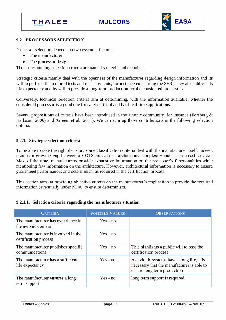
9.2.1.1. Selection criteria regarding the manufacturer situation
CRITERIA POSSIBLE VALUES OBSERVATIONS
The manufacturer has experience in
the avionic domain
Yes – no
The manufacturer is involved in the
certification process
Yes – no
The manufacturer publishes specific
communications
Yes – no This highlights a public will to pass the
certification process
The manufacturer has a sufficient
life expectancy
Yes - no As avionic systems have a long life, it is
necessary that the manufacturer is able to
ensure long term production
The manufacturer ensures a long
term support
Yes - no long term support is required

MULCORS
EASA
Thales Avionics page 34 Réf. CCC/12/006898 – rev. 07
9.2.1.2. Manufacturer openness regarding design and tests information
Design information on a COTS processor is necessary to certify an avionic platform. Such information is
critical because it has a strong impact on the performance of the chip. Therefore, the manufacturer may not
agree to communicate specific design information that would be required to ensure determinism. Then,
with devices of equivalent functionality, it is relevant to favor manufacturers who agree on information
exchange.
Moreover, for an avionic component, it is necessary to perform specific robustness tests, such as a SEE
(Single Event Effect) named also, by processors manufacturer SER (Software Error Rate) determination,
including SEU/MBU estimations. Usually, manufacturers perform such tests on their own for internal use.
CRITERIA POSSIBLE
VALUES
OBSERVATIONS
The manufacturer provides
information on the processor
design
Yes – No –
under NDA
Collaboration with the processor manufacturer is
mandatory in order to provide to the certification
authority enough evidence of mastering the
processor
The manufacturer provides
information on bugs and errata
Yes – No –
Under NDA
Such information is mandatory and a major part of
the collaboration between the certification
applicant and the processor manufacturer
The manufacturer provides
information on SER
(SEU/MBU)
Yes – No –
Under NDA
Usually, manufacturers perform investigations
concerning SER on their own.
9.2.2. Technical selection criteria
Technical selection criteria aim at identifying undesirable features and correlated mitigation means on the
considered processor. For multicore processors, we can distinguish generic selection criteria that are valid
both for multicore and single-core processors, and multicore-specific selection criteria.
We introduce here a non-exhaustive list of generic selection criteria. Multicore specific selection criteria,
that constitute one main contribution of the study, are introduced and explained in the next chapter.
9.2.2.1. Focus on core architecture
The structure of a core has a strong impact on the execution of the embedded software. The components
and services usually found in a core are described here.
Instruction model 9.2.2.1..1
The instruction set (ISA) is one major interface between hardware and software. It can be decomposed into
several categories of instructions:

MULCORS
EASA
Thales Avionics page 35 Réf. CCC/12/006898 – rev. 07
Arithmetical instructions. They can be dedicated to use specific platform services, such as hardware
locks.
Branch instructions, including system calls
Memory instructions
Configuration instructions. They are used to write to specific configuration registers in the core, the
MMU or the cache controller.
Floating point instructions
Usually, an instruction set is defined in a highly exhaustive way, and COTS processors implement a subset
of one or more ISA. Under avionic development constraints, the use of specific instructions can be
forbidden, such as optimized instructions whose execution is non-deterministic.
Some processors support a user-defined extension of the ISA. Specific instructions can be defined and their
execution is given to a specific coprocessor provided by the user. For instance, this is the case when
external floating point units are integrated on a SoC.
We consider the following selection criteria:
CRITERIA COMPONENT/
SERVICE
POSSIBLE
VALUES
OBSERVATIONS
The instruction set is
complete
Instruction
set
Yes – no
No information
An instruction set can be considered as
complete if any non-defined instruction is
decoded as a NOP11
Several different
instruction sets are
supported
Instruction
set
Yes – no
Instructions have the
same length
Instruction
set
Yes – no If no, then it must be proven that the
instruction set is not ambiguous
The instruction set can
be extended
Instruction
set
Yes – no
The instruction set is
fully supported
Instruction
set
Yes – no If not, the platform behavior when
receiving any of the missing instructions
has to be documented
The instruction set
supports hypervisor
privilege level
Privilege
levels
Yes - no This is mandatory if a hypervisor
implementation is expected
Instructions can be
restricted to supervisor
or hypervisor privilege
level by SW
configuration
Instruction
set
Yes – no
No information
This is an elegant mitigation means to
prevent the execution of non-trusted
instructions.
11
NOP : No OPeration

MULCORS
EASA
Thales Avionics page 36 Réf. CCC/12/006898 – rev. 07
Pipeline issues 9.2.2.1..2
The pipeline contains all processing units able to execute a program. The usual stages found in a pipeline
are:
Fetch: fulfilled by the Fetch Unit. It picks the instructions to be executed from a storage device
according to their address. Usually, it implements a pre-fetch service (although a dedicated
component may be in charge of pre-fetch). It can also perform multiple fetches in one clock cycle
and maintain a local instruction queue. The fetch unit is linked to the Branch Unit that implements a
branch prediction algorithm.
Decode and Dispatch: in this stage, instructions are read and routed to the adequate execution units.
Usually, several instructions can be decoded and dispatched in the same cycle. Dispatch rules can
be documented, but usually it is not the case.
Execute: this stage is fulfilled by several processing units. We consider here:
o The Load/Store Unit for data transactions toward the address space. This unit may manage
several concurrent transactions. It also usually reorders read and writes transactions still
maintaining causality when there are dependencies.
o The integer Arithmetical and Logical units (ALU): usually, those units are duplicated to
improve performances. The allocation is performed during the Dispatch stage.
o The floating point arithmetical units (FPU)
The behavior of the Load-Store Unit is usually complex. It is therefore difficult to have a clear view
of the generated activity by the embedded code.
The corresponding criteria are:
CRITERIA COMPONENT/SERVI
CE
POSSIBLE
VALUES
OBSERVATIONS
The instruction unit can
fetch several instructions in
parallel
Pipeline
Instruction unit
Yes – no
No
information
The instruction unit has a
pre-fetch service depending
on a branch unit
Pipeline
Instruction unit
Yes – no
No
information
The pre-fetch is limited
inside a memory page
Pipeline
Instruction unit
Yes – no
No
information
If no, this may raise page faults out
of the software execution flow
The branch prediction can
be disabled
Pipeline
Branch unit
Yes – no
No
information
The branch prediction
policy is configurable
static/dynamic
Pipeline
Branch unit
Yes – no
No
information
A static branch prediction is easier to
analyze

MULCORS
EASA
Thales Avionics page 37 Réf. CCC/12/006898 – rev. 07
The LSU reorders the
memory and IO transactions
Pipeline
Load/store unit
Yes – no
No
information
Transaction reordering is a source of
indeterminism whose impact on
worst case performance has to be
bounded
Transaction reordering can
be forbidden in the LSU
Pipeline
Load/store unit
Yes – no –
partially
No
information
Internal registers are
renamed during instruction
execution
Pipeline
Renaming
Yes – no
No
information
This optimization mechanism
Virtual memory management 9.2.2.1..3
The virtual memory service is provided by the Memory Management Unit (MMU). This component is in
charge of translating virtual addresses into physical addresses, and verifying that the requesting software
has the sufficient access rights. On multicore platforms, this service can be located at core, at platform level
or at both levels.
A MMU usually contains two components: one dedicated to actually translate addresses and check access
rights, and a storage device, such as the Translation Look aside Buffers (TLB) to save locally the address
translation rules. A TLB behaves like a cache, so it has a replacement algorithm that is implemented by
hardware or software.
The virtual memory is defined with pages frames. A page is defined by its size and an offset. The
translation rule contains the page offset, size and access rights. Page sizes can be fixed or variable.

MULCORS
EASA
Thales Avionics page 38 Réf. CCC/12/006898 – rev. 07
We define the following classification criteria:
CRITERIA COMPONENT/SERVIC
E
POSSIBLE VALUES OBSERVATIONS
TLB storage MMU
TLB architecture
TLB hierarchy
(L1/L2,
data/instruction
/unified)
The TLB
replacement
algorithm is
implemented in
hardware or software
MMU
TLB replacement
algorithm
Yes – no – both
No information
A software implementation of
the TLB replacement algorithm
is preferable
The page size is
fixed or variable
MMU Fixed – variable –
both
Variable size pages use
decreases the number of TLB
miss
The MMU detects
pages overlapping
MMU Yes – no
No information
If pages can overlap, this is a
source of indeterminism and a
security failure
Private caches and scratchpads 9.2.2.1..4
The use of hierarchical memory improves the performance of software. We encounter caches and
scratchpads. A scratchpad is usually viewed as a cache with its management implemented by software. For
real-time applications, a classic approach consists of filling the scratchpad with the software’s data and
instructions (when the software’s data and instructions allow it). In a general way, the timing variability
when accessing private caches and scratchpads is considered to be bounded. Content prediction depends on
the cache replacement policy.
The size and the architecture of each cache, scratchpad and memory have a strong impact on software
performance.
We define the following classification criteria:
CRITERIA COMPONENT/SERVI
CE
POSSIBLE VALUES OBSERVATIONS
Private cache and
scratchpad
contents
Private caches and
scratchpads
Architecture
Data – instruction – unified
L1 or L1+L2 hierarchy
Private cache
replacement
policy
Private cache Least Recently Used
Pseudo Least recently
used (documented or
not)
LRU, LFU and FIFO are the
preferred policies for analysis
PLRU needs to be
documented as it is usually

MULCORS
EASA
Thales Avionics page 39 Réf. CCC/12/006898 – rev. 07
Random
Least frequently used
FIFO
implemented with
optimizations for streaming
Random replacement policy is
the worst choice as it is
completely non analyzable
9.2.2.2. Focus on peripherals
Most COTS systems on chip embed hardware accelerators in order to increase the I/O processing
performances. This is especially the case for network processing devices.
In many cases, such hardware accelerators are highly configurable and are granted a large autonomy in
their actions.
We define the following criteria:
CRITERIA COMPONENT/SERVICE POSSIBLE
VALUES
OBSERVATIONS
The overall architecture
is documented
Hardware accelerator
Architecture
Yes - no
The hardware accelerator
embeds microcode
Hardware accelerator
Architecture
Yes – no
Non documented
If yes, this microcode has to be
certified according to ED-
12/DO-178B/C
The hardware accelerator
is able to initiate master
transactions on the
interconnect
Hardware accelerator
Architecture
Yes – no
Non documented
If yes, a worst case load has to
be determined in order to
estimate the occupied bandwidth
on the interconnect
The hardware accelerator
contains internal
memory
Hardware accelerator
Architecture
Yes – no
Non documented
The accelerator internal
memory is protected
against SEU/MBU
Hardware accelerator
Architecture
Yes – no
Not documented
Parity or ECC has to be enforced
The hardware accelerator
can be bypassed
Hardware accelerator Yes – no
Not documented
This criterion is mandatory when
the hardware accelerator
behavior is incompatible with an
avionic usage

MULCORS
EASA
Thales Avionics page 40 Réf. CCC/12/006898 – rev. 07
9.2.2.3. Focus on hardware assist for debug and monitoring
Most COTS processors provide debug mechanisms that enable breakpoint insertion, single step
execution… The usual way to debug bare metal software is to use the JTAG interface. On top of an
operating system, debuggers such as GDB12
can be used.
We define the following criteria:
CRITERIA COMPONENT/SERVI
CE
POSSIBLE VALUES OBSERVATIONS
The processor offers a
service for internal
debugging (step by step
execution and internal
registers view)
Debug service
Core level
Yes – no
Not documented
This is useful to validate a
piece of embedded
software and monitor the
processor behavior during
its execution
It is possible to have a
trace of the transactions
generated by the core
Debug service
Platform level
Yes – no
Not documented
This is useful to have a
direct view of the activity
generated by the core for
interconnect load
estimation
12
GDB: Gnu DeBugger

MULCORS
EASA
Thales Avionics page 41 Réf. CCC/12/006898 – rev. 07
9.3. MULTI-CORE TECHNOLOGY STATE-OF-THE-ART
This chapter covers tasks 1 and 2
9.3.1. Summary of task 1
Identify the types of multi-core processors currently available from the major manufacturers, along with
any that are anticipated in the near future (i.e. the next three years).
The multi-core processors identified should include DSPs (Digital Signal Processors), devices that combine
multiple processor cores with other airborne hardware devices such as Field-Programmable Gate Arrays
(FPGA) and any other types of multi-core processors that the study may reveal.
9.3.2. Summary of task 2
Identify the essential basic architectural characteristics or components of each type of processor and insert
them with the types of processor into a spreadsheet or database that shall be delivered to EASA at the end
of the study. Characteristics that might be taken into account in such a classification might include whether
the cores are homogeneous or heterogeneous, the memory, cache and data bus architectures of the devices,
the number of cores or whichever other criteria the study identifies as being important.
Emphasis shall be placed on features that differ from those of current single core processors and that may
prevent the functions executed on the processors from behaving in a deterministic and robustly partitioned
manner.
These would include features that may enable interference between cores due to common access to
memory, cache, data bus or I/O devices and any features intended to save energy that may dynamically
shut down a core, alter its executing frequency or dynamically alter the number of executing tasks.
Other features to capture in the spread sheet may include the presence of any software or COTS IP that is
provided with the processor and any features to control the hardware or the data transfers between cores
and other components, or to control the execution of any hosted software. The study shall identify any
COTS IP and whether it was developed and verified in compliance with any DAL of ED-12B / DO-178B.
Details in the spread sheet should be limited, such as the title or category of the feature or the number of
processors, with the detailed explanations of the features and their implications being provided in the text
of the report.
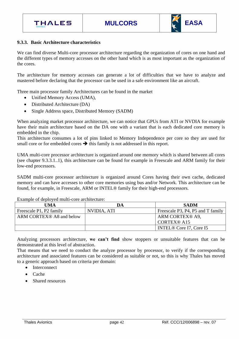
MULCORS
EASA
Thales Avionics page 42 Réf. CCC/12/006898 – rev. 07
9.3.3. Basic Architecture characteristics
We can find diverse Multi-core processor architecture regarding the organization of cores on one hand and
the different types of memory accesses on the other hand which is as most important as the organization of
the cores.
The architecture for memory accesses can generate a lot of difficulties that we have to analyze and
mastered before declaring that the processor can be used in a safe environment like an aircraft.
Three main processor family Architectures can be found in the market
Unified Memory Access (UMA),
Distributed Architecture (DA)
Single Address space, Distributed Memory (SADM)
When analyzing market processor architecture, we can notice that GPUs from ATI or NVDIA for example
have their main architecture based on the DA one with a variant that is each dedicated core memory is
embedded in the chip.
This architecture consumes a lot of pins linked to Memory Independence per core so they are used for
small core or for embedded cores this family is not addressed in this report.
UMA multi-core processor architecture is organized around one memory which is shared between all cores
(see chapter 9.3.3.1..1), this architecture can be found for example in Freescale and ARM family for their
low-end processors.
SADM multi-core processor architecture is organized around Cores having their own cache, dedicated
memory and can have accesses to other core memories using bus and/or Network. This architecture can be
found, for example, in Freescale, ARM or INTEL® family for their high-end processors.
Example of deployed multi-core architecture:
UMA DA SADM
Freescale P1, P2 family NVIDIA, ATI Freescale P3, P4, P5 and T family
ARM CORTEX® A8 and below ARM CORTEX® A9,
CORTEX® A15
INTEL® Core I7, Core I5
Analyzing processors architecture, we can’t find show stoppers or unsuitable features that can be
demonstrated at this level of abstraction.
That means that we need to conduct the analyze processor by processor, to verify if the corresponding
architecture and associated features can be considered as suitable or not, so this is why Thales has moved
to a generic approach based on criteria per domain:
Interconnect
Cache
Shared resources

MULCORS
EASA
Thales Avionics page 43 Réf. CCC/12/006898 – rev. 07
9.3.3.1. Memory sharing architecture
In this chapter we propose to present the different types of memory accesses and the key points associated
with these architectures.
Unified Memory Access (UMA) 9.3.3.1..1
The multi-core processor architecture is organized around one memory which is shared between all cores:
In this type of architecture, Access time to the memory is the same for each processor but we can notice
that this access time is directly linked with the memory bandwidth throughput; Read or Write operation
performed from or to the memory can be only one data per access.
This type of architecture requires arbitration management on one hand and integrity mechanisms on the
other hand to manage communication between cores and synchronization if required.
BUS
Core 1
Core 2
Core n
EXTERNAL MEMORY

MULCORS
EASA
Thales Avionics page 44 Réf. CCC/12/006898 – rev. 07
What about caches? 9.3.3.1..2
UMA architecture is upgraded introducing cache memories; these are high speed memories between cores
and External Memory. These memories have the same class of access time as its dedicated core.
These cache memories introduce other kind of problems linked to data integrity. If two cores share the
same data area, when one of these two manipulate a data item, the second core which has a copy of this
data needs to know that the data item is upgraded by another core (this problem occurs mainly in SMP13
mode where one Operating System manages all cores allocating them to processes for one running
Airborne Software application in a given period of time).
In multi-core processors we need to take care about how Cache Memory Coherency is assumed
13
SMP : Symmetrical Multi Programming
BUS
Core 1
Core 2
Core n
EXTERNAL MEMORY
Cache Cache Cache

MULCORS
EASA
Thales Avionics page 45 Réf. CCC/12/006898 – rev. 07
Distributed Architecture (DA) 9.3.3.1..3
In this Architecture, each core has the use of a dedicated memory with or without dedicated cache
depending on the processor architecture.
A local network realizes the link between cores and it is used for data and/or command transfer
We can find the use of this kind of architecture, with or without caches, mainly in GPUs14
with a variant
where memory is embedded inside the die and dedicated per core. A Network is used to communicate
between cores and the outside.
Cores can be allowed (depending on the implemented policy) to have access directly to the data using the
network. With this kind of architecture, the performance of the global processor is directly linked to the
quality and performance of the local network. We can also speak about this being shared memory
architecture.
Remark: in this architecture, Memory Cache Management is simplified and occurs in the same way as in a
single core processor (separate cache and memory are dedicated to each core).
14
GPU : Graphics processing Unit)
EXT MEMORY
Core 1
Cache
I/F
EXT MEMORY
Core 2
Cache
I/F
EXT MEMORY
Core n
Cache
I/F
LOCAL NETWORK

MULCORS
EASA
Thales Avionics page 46 Réf. CCC/12/006898 – rev. 07
Architecture named “Single Address space, Distributed Memory” or SADM 9.3.3.1..4
This is the last class of processor architecture named SADM where Cores have their own cache, they can
also have dedicated memory but they can have access to other core memories using the bus or the Network.
In this architecture we can notice that we have separate clusters. Each cluster can have its own private
memory shared between cores allocated to this cluster. Exchanges between clusters are realized using local
Network.
Note: In some multi-core architecture, like in QorIQ™ from Freescale or in ARM, the cluster bus is also
part of the global network. In this variant of architecture, the bandwidth is at least dimensioned to sustain
all the transfers in a cluster without causing perturbation to the others (this point has to be verified when
the selection of a multi-core is proposed).
EXT MEMORY
Core 1
Cache
BUS
EXT MEMORY
Core n
LOCAL NETWORK
Core 2
Cache Cache
Core 1
BUS
Core n
Core 2
Cache Cache Cache

MULCORS
EASA
Thales Avionics page 47 Réf. CCC/12/006898 – rev. 07
9.3.4. Multi-core galaxy overview
This analysis is based on public available information; information under NDA can’t be described in this
analysis.
See Excel File where galaxy overview has been developed.
Multicore_processors_roadmap_r2.xlsx
9.3.4.1. A short overview of processor roadmap
We speak about a short overview due to the fact that this chapter can only detailed accessible information
on processor roadmap from the three main actors in the computing domain those are: Freescale, ARM and
INTEL®. Detailed available information on core architectures is in the Excel Spread Sheet.
Freescale Roadmap 9.3.4.1..1
Figure 2: Freescale Roadmap (source: Freescale)

MULCORS
EASA
Thales Avionics page 48 Réf. CCC/12/006898 – rev. 07
First Generation
P1 series is tailored for gateways, Ethernet switches, wireless LAN access points, and general-purpose
control Airborne Software. It is the entry level platform, ranging from 400 to 800 MHz devices
P2 series is designed for a wide variety of applications in the networking, telecom, military and industrial
markets. It will be available in special high quality parts,. It is the mid-level platform, with devices ranging
from 800 MHz up to 1.2 GHz.
P3 series is a mid-performance networking platform, designed for switching and routing. The P3 family
offers a multi-core platform, with support for up to four Power Architecture e500mc cores at frequencies
up to 1.5 GHz on the same chip, connected by the CoreNet™ coherency fabric.
P4 series is a high performance networking platform, designed for backbone networking and enterprise
level switching and routing. The P4 family offers an extreme multi-core platform, with support for up to
eight Power Architecture e500mc cores at frequencies up to 1.5 GHz on the same chip, connected by the
CoreNet™ coherency fabric..
P5 series is based on the high performance 64-bit e5500 core scaling up to 2.5 GHz and allowing
numerous auxiliary application processing units as well as multi core operation via the CoreNet™ fabric.
Applications rage from high end networking control plane infrastructure, high end storage networking and
complex military and industrial devices
Second generation
T series is based on high performance 64 bits e6500 dual-threaded core with ALTIVEC function. The
internal architecture is based on clusters, each containing four dual-threaded cores and one memory
controller and various other accelerators
Third generation
X series: no information can be available for this series.

MULCORS
EASA
Thales Avionics page 49 Réf. CCC/12/006898 – rev. 07
ARM Roadmap 9.3.4.1..2
ARM has a strong reputation as an IP provider and manufacturer of low-power consumption processors. A
lot of microcontrollers implement the ARM IP, and it is the leader on this market.
ARM proposes a set of IP for multicore processors: MPCore™. It contains an IP for an interconnection:
Corelink™. This highly configurable interconnection can support several ARM bus protocols: AMBA®
ACE, AMBA® AXI, AHB, AHB-Lite, and APB. It supports three kinds of cores: CORTEX®-A9,
CORTEX®-A15 and ARM11, and it can connect up to 4 cores.
ARM components’ architectures are open and documented. This goes in favor of being a good candidate
for use in avionics and for further assessment.
CORTEX®A15 is based on a 1 to 4 core product, SMP within a single processor cluster up to 2,5 GHz. Its
4 core version is designed for used in Home & Web servers, Wireless Infrastructure Equipment, Digital
Home entertainment and its 2 core version is designed for Smartphone and Mobile Computing.
CORTEX® A9 is based on a 1 to 4 core product. It is designed for Mainstream Smartphones, Tablets, Set
top boxes, Home Media Players, Auto Infotainment, Residential Gateways and the 1st generation ARM
low power server.
CORTEX® A8 is based on a single core processor with a Frequency range from 600MHz to 1GHz. It has
been designed for Smartphones, Netbooks, Set-up Boxes, Digital TV, Home networking and Printers.
No public information are available after CORTEX®A15
Figure 3: ARM Roadmap (source: ARM)

MULCORS
EASA
Thales Avionics page 50 Réf. CCC/12/006898 – rev. 07
INTEL® ROADMAP 9.3.4.1..3
Figure 4: INTEL Roadmap (source: INTEL)

MULCORS
EASA
Thales Avionics page 51 Réf. CCC/12/006898 – rev. 07
INTEL®
proposes a large variety of multicore processors for domestic, professional or embedded use, We
propose to give below a quick overview of the existing series
INTEL® Atom™:
o This series of processors is dedicated to embedded systems (on this market, the leader is
ARM). The current generation is the third one with dual-core products. There are two major
series: the D(esktop) and the N(etbook). A particularity is the memory hierarchy stack: there
is only one shared cache for all the cores.
INTEL® Core™ i7:
o This series is dedicated to a domestic use (desktop applications, gaming…). The current
generation is the second one (released in late 2011) and is composed of 2, 4 and 6 core
processors. They embed the classic INTEL® optimizations (turbo boost, support for
virtualization). Their memory hierarchy is two level of private cache per core, and a level of
shared cache. An extension to this series is the Intel® Core™ i7 Extreme.
Intel® Core™ i5:
o This series is similar to the Intel® Core™ i7, except it is composed of 2 and 4 cores
processors. Globally, the performance of those processors is lower than those from the
Intel® Core™ i7 series.
Intel® Core™ i3:
o This series is similar to the two previous ones, except it is only composed of dual-core
processors, with worse performance.
Intel® Celeron™:
o A Celeron is a processor belonging to another series with limited capacity and a lower cost.
This series contains some dual-core processors.
Intel® Core™ 2:
o This series contains different types of processors, some dedicated to desktop applications,
some dedicated to high performance and some dedicated to low consumption. This series is
composed of 1, 2 and 4 cores processors.
Intel® Pentium™:
o This series contains some low-cost dual core processors.
INTEL® doesn’t give out any more public information than that collected in this short term Roadmap.
Available information has a one year limitation and is focused around the new bridge (no information on
internal features) and around new core performance.

MULCORS
EASA
Thales Avionics page 52 Réf. CCC/12/006898 – rev. 07
9.3.4.2. Multi-core processors manufacturers and addressed market segments
The multi-core technology can be used in several market segments. A non-exhaustive list of such segments
is provided below:
Application Domain Expected characteristics Manufacturers
Desktop and
gaming applications
Correct average performance for general
operations and floating points operations.
No real-time guarantees are required.
INTEL®, AMD, IBM,
Broadcom Corp
Multimedia
applications
Fast integer and floating point calculus,
required in image and video processing.
The corresponding systems may consider
soft real time constraints in order to be
reliable in stream processing.
Nvidia, AMD, Texas
Instruments, VIA,
Freescale, Broadcom Corp
Safety applications
(automotive,
medical, spatial,
defense, avionics)
High level of integrity and hard real time
performance.
Robustness under aggressive
environmental constraints is very
important, especially in spatial
applications.
Aeroflex Gaisler (spatial),
ARM, Freescale, IBM,
Texas Instruments, Marvell,
Infineon (defence and
aerospace)
Parallax Semicond
(medical)
Automotive (low
critical
functionalities)
Low-power consumption, reliability and
soft real-time constraints Freescale, Infineon
Networking
applications
(mainly switches
and servers)
High bandwidth in network processing and
correct platform integrity.
Because those applications are usually in
contact with the open world, security
features, including partitioning, are very
important.
Oracle, IntellaSys,
Freescale, IBM, Broadcom
Corp, Cavium Corp, Tilera,
Marvell, Fujitsu
High performance
industrial
applications
High bandwidth in network processing and
extremely fast integer and floating points
operations for digital signal processing.
Texas Instruments,
IntellaSys, Cavium Corp,
IBM, Fujitsu.
Low power
embedded
applications
Acceptable performance while limiting the
power consumption.
ARM core IPs
Infineon, Nvidia, Freescale,
Texas Instruments,
Broadcom Corp

MULCORS
EASA
Thales Avionics page 53 Réf. CCC/12/006898 – rev. 07
9.3.4.3. Academic projects around multi-core
Several academic projects address multi-core concerns for hard real-time systems, including Embedded
Aircraft Systems. Those projects aim at introducing new hardware and software concepts in classic multi-
core architectures to enforce determinism and real-time behavior on virtual or synthesized platforms. Such
concepts can be implemented on general purpose COTS processors if processor manufacturers can find
some commercial interest.
In the state-of-the-art of academic projects dealing with predictability on multi-core platforms, we found
the relevant projects:
MERASA, parMERASA: This project (Multi-Core Execution of Hard Real-Time Applications
Supporting Analysability) and its extension aim at proposing a set of tools and recommendations
for predictability and WCET analyses on a multi-core architecture. The first project is finished now
and it proposes the following tools :
o A fully FPGA synthesizable multi-core processor targeting
o A SystemC simulator of determinist multi-core platform
o WCET analyses tools for embedded software. They are based on the open-source library
Otawa and on the proprietary tool Rapitime.
JOP: This is a FPGA implementation of a multi-core processor executing java bytecode. It comes
with a configurable deterministic interconnect bus and a predictable memory. This project explores
some possible optimizations for the interconnect configuration.
MUSE: This project deals with real-time multi-core for spatial platforms. They address problems
close to fault-tolerance. This project’s concerns are close to Embedded Aircraft Systems concerns.
Indeed their main lock is the parallelization of critical operations.
ARAMiS: This project was launched by the German government in the end of 2011. It aims at
developing concepts that could enable the use of multi-core platforms in automotive, railway and
Embedded Aircraft Systems.

MULCORS
EASA
Thales Avionics page 54 Réf. CCC/12/006898 – rev. 07
9.3.4.4. Industrial collaborations
In this chapter, we address the two main initiatives around multi-core:
MCFA (Multi-Core For Avionics) initiative was launched by Freescale in early 2011 with the
major actors of Embedded Aircraft Systems, a detailed list of actors and objectives can be found on
the MCFA website :
http://media.freescale.com/phoenix.zhtml?c=196520&p=irol-newsArticle&ID=1606741&highlight
The Multi-core Association® (MCA) is an industry association that includes leading companies
implementing products that embrace multi-core technology. Their members represent vendors of
processors, operating systems, compilers, development tools, debuggers, ESL/EDA tools,
simulators, application and system developers, and universities. Their primary objective is to define
and promote open specifications to enable multi-core product development. The complete list of
actors can be found on their website : http://www.multicore-association.org/
9.3.5. Software support for Embedded Aircraft Systems
9.3.5.1. Airborne Certified Operating System
A wide community of actors act in Avionics Embedded Software, a sum-up is given below:
Wind River with two class of Operating System
o VxWorks CERT Platform – Certified Operating System based on VxWorks compliant with
ED-12B/DO-178B
o VxWorks 653 Platform – Operating System featured from VxWorks with an ARINC653
API supporting DO-197
Green Hills Software which provides
o Integrity-178B RTOS15
which offers an ARINC653 API
o GMART, an ADA run-time compliant with ED-12B/DO-178B level A
o Integrity Multivisor : an hypervisor that offers virtualization to help hosting a wide diversity
of Operating System
SYSGO which provides
o PikeOS a micro-kernel offering both a RTOS and a virtualization concept
LynuxWorks which provides
o LynxOS-178a RTOS offering via Virtual Machine a virtualization concept
o LynxOS 178 is a FAA – accepted Reusable Software Component (RSC)
DDC-I which provides
o DEOS, a RTOS certified up to level A supporting ARINC653 part4
o HeartOS, a micro-kernel POSIX Based certified to ED-12B/DO-178B up to level A
15
RTOS : Real Time Operating System

MULCORS
EASA
Thales Avionics page 55 Réf. CCC/12/006898 – rev. 07
THALES Avionics which provide
o MACS2, an ARINC653 Operating System certified up to level A and supporting
Incremental Certification.
This is a non-exhaustive list of Operating System providers and Operating System used in embedded
certified Embedded Aircraft Systems
Some OS providers offer virtualization techniques to help the hosting of different Operating Systems in
different temporal slots, these techniques are mainly based on what it is called micro-kernel.
Most of these Operating System providers offer a multi-core approach of their solution based only on
compatibility with ED-12B/DO-178B or ARINC653 but without a real analysis on how to manage the
multi-core processor regarding the certification point of view.
9.3.5.2. Software definition / explanation
Processes and Threads 9.3.5.2..1
Threads differ from traditional multitasking operating system processes in that:
Processes are typically independent, while threads exist as subsets of a process
Processes carry considerably more state information than threads, whereas multiple threads within a
process share process state as well as memory and other resources
Processes have separate address spaces, whereas threads share their address space
Processes interact only through system-provided inter-process communication mechanisms
Context switching between threads in the same process is typically faster than context switching
between processes.
Multithreading 9.3.5.2..2
Multi-threading is a widespread programming and execution model that allows multiple threads to exist
within the context of a single process.
These threads share the process' resources, but are able to execute independently. The threaded
programming model provides developers with a useful abstraction of concurrent execution. However,
perhaps the most interesting application of the technology is when it is applied to a single process to enable
parallel execution on a multiprocessing system.
Processes, kernel threads, user threads 9.3.5.2..3
A process is the "heaviest" unit of kernel scheduling.
Processes own resources allocated by the operating system. Resources include memory, file handles,
sockets, device handles, and windows. Processes do not share address spaces or file resources except

MULCORS
EASA
Thales Avionics page 56 Réf. CCC/12/006898 – rev. 07
through explicit methods such as inheriting file handles or shared memory segments, or mapping the same
file in a shared way. Processes are typically preemptively multitasked.
A kernel thread is the "lightest" unit of kernel scheduling.
At least one kernel thread exists within each process. If multiple kernel threads can exist within a process,
then they share the same memory and file resources. Kernel threads are preemptively multitasked if the
operating system's process scheduler is preemptive.
Threads are sometimes implemented in userspace libraries, thus called user threads.
The kernel is not aware of them, so they are managed and scheduled in userspace. Some implementations
base their user threads on top of several kernel threads to benefit from multi-processor machines.
9.3.5.3. The impact of multi-cores on Software Development
Memory Management 9.3.5.3..1
Multi-core processor offers opportunities to increase performance and reduce footprint (size weight and
power dissipation).
Multi-core presents a new challenge to deal with, how to take benefit of these cores, currently not much
Airborne Software can benefit from such advantages due to the complexity of parallelization. Each core
contains its own set of execution resources, resulting in very low latency parallel execution of Airborne
Software threads within a single physical CPU package.
The benefits of multi-core processors are not limited to increased performance. Multi-core processors
provide greater system density, allowing organizations to maximize the productivity of their available floor
space.
Since they operate at lower frequencies, multi-core processors use less power and generate less heat per
core than the commensurate number of single-core processors
MM_REM1: Most of the multi-cores share their front side bus as well as the last level of cache. Regarding
this, it is possible for one core to saturate the shared memory bus resulting in degradation of performance
and safety.
The front side bus, which is also known as the memory bus, is the "highway" upon which data travels as it
is written to or read from memory.
“Memory bandwidth” is the amount of data that can travel on the memory bus in a given period of time
usually expressed in MBps16
or Gbps17
. Although improvements in memory system performance have
historically lagged behind improvements in processor performance, the chip manufacturers are working
hard to close the gap.
But even if they're successful, if the new multi-core chips implement significantly faster memory systems,
as long as the memory bandwidth is shared between the cores, there will always exist the potential for
bottlenecks.
16
MBps : Mega-Byte per second 17
Gbps : Giga-bits per second

MULCORS
EASA
Thales Avionics page 57 Réf. CCC/12/006898 – rev. 07
And as the number of cores per processor and the number of threaded Airborne Software applications
increases, the performance of more and more Airborne Software applications will be limited by the
processor’s memory bandwidth.
One approach per example can be:
One technique which mitigates this limitation is to intelligently schedule jobs onto these processors,
managing the memory bandwidth demand versus its supply. Avionics Airborne Systems can be configured
to automate this technique when hosting high DAL level Airborne Software.
At Avionics Airborne System level, with the use of an Hypervisor, the "memory bandwidth resource" that
represents the amount of available memory bandwidth is created and assigned to each core. The value of
this "memory bandwidth resource" can be configured on each core by the Hypervisor itself. The memory
bandwidth resource is now shared among the Airborne Software applications running on the different cores
of the Multi-core processor.
Mapping 9.3.5.3..2
In advanced parallel processing Airborne Software, the final step in this process is mapping the threads to
cores. In our assignments, this mapping can be done by the Operating System statically or dynamically
regarding available core resources.
We have introduced recommendations on this point in this report.
If Airborne Software is developed using processes or threads, it is possible to take benefit of this
development for addressing a multi-core component. To succeed in process or thread allocation, we need to
understand what are the processes that can be executed simultaneously, which means we need to have
detailed knowledge of the Airborne Software.
There are many dedicated tools to help programmers to map threads onto the cores for INTEL®
processors, and Airborne Operating Systems for multi-cores (Greenhills, Wind River, Sysgo, LynuxWorks,
etc.) help programmers to execute this mapping.

MULCORS
EASA
Thales Avionics page 58 Réf. CCC/12/006898 – rev. 07
9.3.6. Examples of representative multi-core architectures
In this chapter we present a set of COTS multi-core architectures whose technologies are representative of
the different targets described previously:
Networking
Low power embedded systems
High processing performances
We also detail a SoC18
FPGA19
fabric that embeds several items of ARM core IP20
, but leaves the
interconnect implementation to the programmer. The objective is to give a concise view of the different
technologies and services deployed in the cores, interconnects and peripherals.
Remark to partition or virtualize the cores, there are Hypervisors provided for the multi-core processor
directly by the component manufacturer such as TOPAZ for Freescale QorIQ™ family or XEN for
INTEL®
or directly by the Operating System provider, their features and characteristics have to be
analyzed ‘case per case’ to ensure that their could not impair / reduce confidence in the application safety.
9.3.6.1. Communication and Networking Processor
Freescale QorIQ™ P2020 9.3.6.1..1
The QorIQ™ P2 platform series, which includes the P2020 and P2010 communications processors, is
dedicated for a wide variety of applications in the networking, telecom, military and industrial markets.
This processor delivers dual- and single-core frequencies up to 1.2 GHz on a 45 nm technology low-power
platform.
The QorIQ™ P2 series consists of dual- and single-core scaling from a single core at 533 MHz (P1011) to
a dual core at 1.2 GHz (P2020).
The P2020 and P2010 communications processors both have an advanced set of features:
Two e500 Cores
The 64-bit memory controller offers future-proofing against memory technology migration with
support for both DDR2 and DDR3. It also supports error correction codes, a baseline requirement
for any high-reliability system.
Other memory types such as flash are supported through the 16-bit local bus,
USB21
, SD/MMC and serial peripheral interface (SPI).
18
SoC : System on Chip 19
FPGA : Field Programmable Gate Array 20
IP : Intellectual Property

MULCORS
EASA
Thales Avionics page 59 Réf. CCC/12/006898 – rev. 07
9.3.6.1..1.1 e500 Coherency Module (ECM) and Address Map
The e500 coherency module (ECM) provides a mechanism for I/O-initiated transactions to snoop the bus
between the e500v2 cores and the integrated L2 cache in order to maintain coherency across local
cacheable memory. It also provides a flexible switch-type structure for core- and I/O-initiated transactions
to be routed or dispatched to target modules on the device.
The P2020 supports a flexible 36-bit physical address map. Conceptually, the address map consists of local
space and external address space. The local address map is supported by twelve local access windows that
define mapping within the local 36-bit (64-Gbyte) address space.
The P2020 includes the address translation and mapping units (ATMUs) to make part of a larger system
address space through the mapping of translation windows. The ATMUs allows the P2020 to be part of
larger address maps such as those of PCI Express or RapidIO
In such an ECM, the Airborne Embedded System provider has to obtain from the processor manufacturer
knowledge of all the included features and mechanisms that can be disabled for safety requirements.
21
USB : Universal Serial Bus
Figure 5: P2010 : 2020 Overview (source: Freescale Fact Sheet)

MULCORS
EASA
Thales Avionics page 60 Réf. CCC/12/006898 – rev. 07
e500mc Cores 9.3.6.1..2
The e500mc core (see Figure 6) is a recent update of a long series of PowerPC cores developed by
Freescale. It was released in 2008 for the PowerQUICC series and the QorIQ™ series.
Figure 6: e500mc PowerPC core overview (source: Freescale e500mc Reference Manual)

MULCORS
EASA
Thales Avionics page 61 Réf. CCC/12/006898 – rev. 07
We sum up the essential features of e500mc cores in the following table:
Internal component Features
Pipeline 6 stages pipeline
out-of-order execution, and in-order completion
Instruction set Power ISA v 2.06 (partially supported)
Privilege levels User and super-user mode
Guest and non-guest mode (used by the hypervisor)
Fetch unit Fetch up to 4 instructions in the same clock cycle
Pre-fetching policy documentation access restricted
Load/Store Unit Out-of-order load/store execution (still ensuring coherency)
Branch Unit Static/dynamic branch prediction
Caches
Separated 32k Data and instruction L1 caches
Unified 128k L2 Cache
Snoop mechanisms for cache coherency
Cache pre-filling and locking mechanisms through dedicated instructions
L1 Cache replacement policy: LRU
L2 Cache replacement policy: PLRU
L1 Cache implements parity protection, L2 Cache implement ECC
MMU
Two level Translation Look aside Buffers (TLB) tables
L1TLB coherency ensured regarding L2TLB contents
L2TLB management has to be implemented in the embedded software
Bus interface Partial documentation available under NDA
Debug and monitoring 4 Performance Monitor Registers counters may observe 128 different events.

MULCORS
EASA
Thales Avionics page 62 Réf. CCC/12/006898 – rev. 07
Hypervisor 9.3.6.1..3
To manage its multi-core processor family, Freescale has developed and provide a Hypervisor named
TOPAZ which manages:
Security and separation
Messaging among cores
System-level event handling
Debug support
TOPAZ is considered as a small hypervisor for embedded systems based on Power Architecture
technology, it initial version focuses on static partitioning (TOPAZ is not a scheduler):
CPUs, memory and I/O devices can be divided into logical partitions
Partitions are isolated one from the other
Configuration is fixed until a reconfigure and system reboot
TOPAZ not address the problem of multiple operating systems on 1 CPU
TOPAZ has been developed for the QorIQ™ family and it uses a combination of full-virtualization and
para-virtualization which offers performances and minimal changes to guest operating systems (impact on
BSP layer).
TOPAZ Hypervisor has been developed to minimalize “intrusivity” and it offers a limited set of services
such as interrupt controller, inter-partition interrupts, byte-channels, power management, active / standby /
failover and error management.
Memory I/F
Core Core
Operating
SystemDrive
r
Drive
r
Drive
r
Operating
SystemDrive
r
Drive
r
Drive
r
Core
Operating
SystemDrive
r
Drive
r
Drive
r
INTERCONNECT
HW Accelerator
Bus I/F
Network I/F
Memory I/F
Hypervisor
API
Appli.1 Appli.3Appli.2
P1
P2
P3
P4
P1
P2
P3
P1
P2
L1 L2 L1 L2 L1 L2
L3 Cache I/F
HW AcceleratorHW Accelerator
API
Appli.1 Appli.3Appli.2
P1
P2
P3
P4
P1
P2
P3
P1
P2
API
Appli.1 Appli.3Appli.2
P1
P2
P3
P4
P1
P2
P3
P1
P2

MULCORS
EASA
Thales Avionics page 63 Réf. CCC/12/006898 – rev. 07
Networking platform: Freescale QorIQ™ P4080 9.3.6.1..4
The QorIQ™ series is initially dedicated to networking. Yet it is viewed in the avionic community as a
good candidate to analyze effort to reach acceptance of such a multi-core processor in Embedded Aircraft
Systems.
Thanks to the MCFA initiative from Freescale to help Aircraft Embedded Equipment provider conducting
their acceptance process on the QorIQ™ series.
The QorIQ™ P4080 (see Figure 7) integrates eight cores and a large set of hardware accelerators for fast
stream processing.
Figure 7: P4080 Overview (source: Freescale Fact Sheet)

MULCORS
EASA
Thales Avionics page 64 Réf. CCC/12/006898 – rev. 07
9.3.6.1..4.1 QorIQ™ Processor Interconnect
In QorIQ™ processor, the interconnect is named Corenet™. Its complete architecture is proprietary and
less documented; this is the case for the main majority for all manufacturers, so in this report, we have
focused on the interconnect and recommendations to master its behavior.
The interconnect implements the following services:
Arbitration and transfer of transactions between a set of master nodes (Cores, Ethernet controllers
through the Frame Manager, DMA22
engines) and the slave nodes (DRAM23
controller, I/O). A
maximum of four transactions may be arbitrated in each CoreNet™ cycle. A transaction is 128
bytes width. It corresponds to a cache line. The CoreNet™ protocol is said to be lossless.
2x1024k Shared L3 cache level (CoreNet™ Platform Cache)
Peripheral Access Management Units (PAMU): they play a role close to an MMU24
for the
different peripherals
Debug facilities: Aurora interface for real-time debug
Freescale is actively working to be able to provide sufficient guarantees on Corenet™ behavior without
divulging the core information on its internal architecture, thanks to MCFA.
9.3.6.1..4.2 Peripherals
The P4080 provides a large set of peripherals and I/O’s25
. The most important one is the Data Path
Acceleration Architecture (DPAA). It is composed of a set of hardware accelerators that can:
Initiate DMA transfers from several I/O’s, such as PCIe or Ethernet bus
Reassemble, encrypt/decrypt and parse packets
Manage packet buffers
Dispatch packets among dedicated cores for processing, with load-balancing if necessary
The other main peripherals are:
The Enhanced Local Bus Controller (ELBC): This bus connects peripherals usually met in
microcontroller architectures: UART, flash memories, I2C interfaces, SPI interface…
The Ocean network: This network interconnects several PCIe controllers and Serial RapidIO
interfaces. It is completed with DMA controllers.
Peripherals Internal memories include ECC protection. Proprietary microcode is embedded in some
elements of the DPAA.
22
DMA : Direct Memory Access 23
DRAM :Dynamic Random Access Memory 24
MMU : Memory Management Unit 25
I/O : Input / Output

MULCORS
EASA
Thales Avionics page 65 Réf. CCC/12/006898 – rev. 07
9.3.6.2. Low-Power Multi-core IP: ARM CORTEX®-A15 MPCore™
ARM released the MPCore™ series to provide an IP of scalable, highly configurable and low-power multi-
core processors.
This series comes as a set of several IPs for various components (cores, interconnect, peripherals)
We describe here the CORTEX® A15 MPCore™ (see Figure 8) as the most recent processor in this series.
It is organized as a cluster of up to four cores connected with a Snoop Control Unit containing a L2 cache
level.
Some implementations embed several clusters, enabling the use of more than four cores.
The interface with the peripheral bus implements the latest version of the Advance Microcontroller Bus
Architecture (AMBA®) protocol: AMBA® ACE.
Figure 8: ARM CORTEX®-A15 MPCore™ Overview (Source: CORTEX®-A15 Technical Reference Manual r3p0)

MULCORS
EASA
Thales Avionics page 66 Réf. CCC/12/006898 – rev. 07
CORTEX®-A15 Cores 9.3.6.2..1
Mains ARM CORTEX®-A15 features are:
Internal component Features
Instruction set
ARM v7-A
THUMB™
JAZELLE™ (execution of Java Bytecode)
Pipeline 8 stages pipeline
Fetch Unit Static/dynamic branch prediction
Caches Separated Data and instruction 32k L1 caches
LRU replacement policy for all caches
MMU
Two level Translation Lookaside Buffers (TLB). L1 TLB is separated
data/instructions. L2 TLB is unified.
Hardware translation table walk in case of L2 TLB miss
Interrupts Shared interrupts managed by the Generic Interrupt Unit
Bus interface Direct connection to the Snoop Control Unit
Snoop Control Unit: First Level interconnect 9.3.6.2..2
The Snoop Control Unit (on Figure 8: Non processor/Level 2) is the “inter-core interconnect”. It is the first
shared resource between the cores.
The Snoop Control Unit provides the following services:
Arbitration and transport of memory requests for each core
Management of the shared L2 cache, whose size is configurable between 512K and 4M. It
implements an optimized MESI protocol for cache coherency.
Support for inter-cache data and instruction transfers.
AMBA® ACE master Interface with the main interconnect (Corelink™, described further)
Cache coherency acceleration through the Acceleration Coherency Port
Snoop requests (requests from the cores to the addressed space) are therefore interleaved in the Snoop
Control Unit. They are propagated on the single AMBA® ACE master interface to the second level
interconnect. However, this protocol allows several concurrent transactions to be interleaved. Multiple
accesses can therefore occur.

MULCORS
EASA
Thales Avionics page 67 Réf. CCC/12/006898 – rev. 07
Corelink™ Network: Peripheral interconnect 9.3.6.2..3
The connection between the Snoop Control Unit and the main RAM, L3 cache and peripherals is provided
by Corelink™. It is a dedicated IP for on chip networks. It may interconnect several clusters of ARM
MPCore™.
This interconnect implements the AMBA® ACE protocol for nodes (masters and slaves) connections.
Older versions are limited to AMBA® AXI protocol. It is a full crossbar, and it comes with a set of
services for transaction management:
Priority (quality of service) of transactions configuration
Latest granted first arbitration policy in the same domain of priority
Transactions monitoring and performance measurements
Hardware assist for atomic access insurance
Figure 9: Corelink™ Example of implementation (source ARM infocenter - Corelink™ CCI400 Cache coherent interconnect Technical Reference Manual)

MULCORS
EASA
Thales Avionics page 68 Réf. CCC/12/006898 – rev. 07
Trust Zone implementing protections between secure and non-secure transactions. The Trust Zone
is used for hypervisor implementation.
9.3.6.3. Multi-core DSP: Texas Instruments TMS320C6678™
Texas Instruments proposes the TMS320C66xx™ series of multi-core DSPs for multimedia infrastructures,
high performance image processing and medical applications.
The TMS320C66xx™ series proposes high processing capabilities with up to 8 DSP cores, a highly
configurable interconnect and a subsequent set of IO.
We focus here on the TMS320C6678™ octo-core DSP processor (see Figure 10).
Figure 10: TMS320C6678™ architecture overview Source: TMS320C6678™ Multicore Fixed and Floating-point Digital
Signal Processor – Rev C

MULCORS
EASA
Thales Avionics page 69 Réf. CCC/12/006898 – rev. 07
DSP Cores: C66x™ CorePac 9.3.6.3..1
DSP Cores are optimized for vector scalar product operations.
The C66x™ CorePac contains the C66x™ DSP and a set of hardware components that stand between the
core and the interconnect.
They provide the functionalities we classically find in a general purpose core:
Cache levels
Memory management and protection
Bus interface
Interrupt controller
Figure 11: CorePac overview Source: C66x™ CorePac User Manual rev B
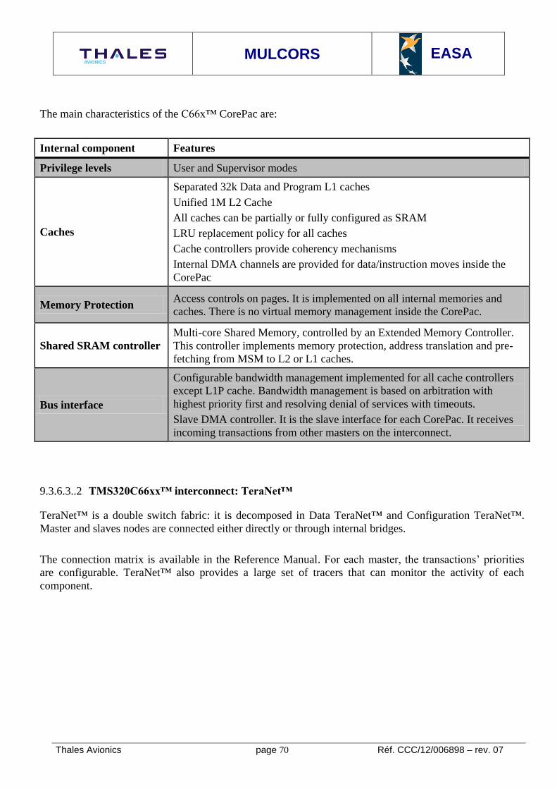
MULCORS
EASA
Thales Avionics page 70 Réf. CCC/12/006898 – rev. 07
The main characteristics of the C66x™ CorePac are:
Internal component Features
Privilege levels User and Supervisor modes
Caches
Separated 32k Data and Program L1 caches
Unified 1M L2 Cache
All caches can be partially or fully configured as SRAM
LRU replacement policy for all caches
Cache controllers provide coherency mechanisms
Internal DMA channels are provided for data/instruction moves inside the
CorePac
Memory Protection Access controls on pages. It is implemented on all internal memories and
caches. There is no virtual memory management inside the CorePac.
Shared SRAM controller
Multi-core Shared Memory, controlled by an Extended Memory Controller.
This controller implements memory protection, address translation and pre-
fetching from MSM to L2 or L1 caches.
Bus interface
Configurable bandwidth management implemented for all cache controllers
except L1P cache. Bandwidth management is based on arbitration with
highest priority first and resolving denial of services with timeouts.
Slave DMA controller. It is the slave interface for each CorePac. It receives
incoming transactions from other masters on the interconnect.
TMS320C66xx™ interconnect: TeraNet™ 9.3.6.3..2
TeraNet™ is a double switch fabric: it is decomposed in Data TeraNet™ and Configuration TeraNet™.
Master and slaves nodes are connected either directly or through internal bridges.
The connection matrix is available in the Reference Manual. For each master, the transactions’ priorities
are configurable. TeraNet™ also provides a large set of tracers that can monitor the activity of each
component.

MULCORS
EASA
Thales Avionics page 71 Réf. CCC/12/006898 – rev. 07
9.3.6.4. SoC FPGA Hard Processor System: Altera Cyclone® V
To improve FPGA device performance, FPGA manufacturers include core IP in their FPGA devices.
This is called the Hard Processor System (HPS). It includes an ARM MPCore™ implementation
containing cache levels and Snoop Control Unit and AMBA® interfaces.
The peripheral interconnect (equivalent of Corelink™ for ARM MPCore™) has to be synthesized inside
the FPGA. External peripherals (external memory, Ethernet controller, PCIe) are provided inside the
system on chip.
We propose as an example the Cyclone® V from Altera. It integrates two ARM CORTEX®-A9 cores
connected with a Snoop Control Unit (see Figure 12).The FPGA fabric is dedicated to:
The high-bandwidth interconnect for external DDR26
, PCIe, Ethernet
Optional coprocessors and classic FPGA systems
26
DDR : Double Data Rate (for a Dynamic Random Access Memory)
Figure 12: Altera Cyclone® V SoC FPGA overview (Source: SoC FPGA Product Overview Advance Information Brief, ref AIB-01017-1.3)

MULCORS
EASA
Thales Avionics page 72 Réf. CCC/12/006898 – rev. 07
9.4. MULTI-CORE FEATURES REGARDING CERTIFICATION
9.4.1. Introduction
In this section, we plan to provide a list of usual services found in a multicore platform. This list will be
used further to establish a classification of multicore processors. The considered criteria deal with the
processor structure and configurability, but also with the available information and more generally the
manufacturer’s openness toward the certification process.
Some criteria address the technological evolution of the platform’s internal components but are not limited
to multicore processors.
This is the case for optimization mechanisms introduced in the cores to improve performance. Other
criteria are multicore specific. They would be irrelevant for an analogous single-core platform. Those
criteria deal essentially with interconnect and shared component features that implement specific
mechanisms to manage the parallel execution of software on each core.
The main novelty in the use of multi-cores in the Avionics domain is the presence of true parallelism
between different pieces of software executed in the same period of time on different cores. This section
deals with the consequences of such parallelism inside the Airborne Embedded System.
Moreover, the design of multi-core processors followed the recent evolutions of embedded technologies.
Thus additional features may occur, but they would also be relevant in a single-core context.
In the following chapters of this report,
we used the Symbol RGL for Recommended Guide-Line abbreviation

MULCORS
EASA
Thales Avionics page 73 Réf. CCC/12/006898 – rev. 07
9.4.2. Processor features impact on determinism
This chapter deals with tasks 3 and 4
9.4.2.1. Summary of task 3
Determine whether it is possible to classify the multi-core processors listed in the spread sheet into groups
according to their components, the characteristics of their architectures, their behaviors or other criteria.
The study shall describe the criteria used to classify the processors and why those criteria were selected.
The groups may later be used by EASA to write guidance material that is specific to each group.
9.4.2.2. Summary of task 4
Select - in agreement with EASA - a representative processor from each of the identified processor groups
and conduct a detailed examination of the internal architecture of that processor, identifying the
components involved and the features of the processors, describing their roles in the data and control flow
of the device. Emphasis should again be on features that are not found on most single core processors.
Aspects that are common to many types or groups only need to be described once in the study report, but
any important variations that are specific to a processor or group of processors shall be highlighted.
While identifying and describing processor features, identify which of the components, features or
behaviors of the processor groups are unsuitable for the use of the processors in safety-critical airborne
systems with deterministic behavior and in compliance with the current guidance material listed above. The
features listed in item 2 above and the reasons why they are unsuitable should be described. Any other type
of interference or effect identified by the study that might make a component or architecture unsuitable for
use in certifiable and deterministic safety-critical airborne systems should be identified and described.
9.4.2.3. Interconnect
Overview 9.4.2.3..1
The Interconnect is the first shared resource between cores. It interleaves the concurrent transactions sent
by the cores to the shared resources like caches, memories and I/O mapped in the address space. Its
architecture has a strong impact on determinism and ensuring partitioning, and on the complexity of worst
case analyses.
An interconnect usually implements the following services:
Arbitration of incoming requests. This stage depends on several parameters:
o Arbitration rules
o Arbiter internal logic
o Network topology

MULCORS
EASA
Thales Avionics page 74 Réf. CCC/12/006898 – rev. 07
Allocation of the physical destination devices when they are duplicated. This is the case for
example when there is more than one MEMORY controller.
Allocation of a path to the destination. This is necessary when several paths exist between the
source and the destination. This depends on the routing rules.
Support for atomic operations, hardware locking mechanisms
Snooping mechanisms for cache coherency
Inter Processors Interruptions (IPI) for inter-core communications
The Interconnect is in charge of interleaving - when necessary - the transaction flows emitted by the master
nodes (the cores and specific I/O such as Ethernet controllers or DMA engines) directed to slave nodes
(usually MEMORY, shared caches, slave I/O and core slave interface).
An interconnect is usually characterized by:
A Protocol: The different stages of a transaction processing. Most interconnects protocols are
divided in three phases: arbitration, transfer and termination.
A Topology: The different point-to-point connections between nodes. The most classic topologies
are:
o Busses: One connection links all masters to all slaves. A bus may be duplicated on a chip
(we talk about multiple busses), thus allowing multiple parallel transfers. A bus may be
pipelined, allowing several transactions to be transferred at the same time in different
pipeline steps. In case of duplicated busses, the arbitration module will allocate one bus to
one master when arbitrating his transaction.
o Crossbars: There is one point to point connection between each master and slave. Thus no
routing is necessary. Usually, a local arbitration module is provided on each slave interface
to interleave incoming accesses.
o Switch fabrics: This is the intermediate topology: point-to-point connections link internal
bridges that are connected to the master and slave interfaces. The arbiter is in charge of
routing the incoming transactions inside this network. This solution is a usual compromise
between the number of point-to-point connections and the interconnect performance through
parallel transaction service.
An Arbitration policy: The rules that are applied to access sequentially an atomic resource that was
requested by different masters at the same time. Usually, the arbitration policy is designed for good
average performance and granting fair access to the requesters. One example is the Least Recently
Granted arbitration policy that is implemented in Corelink™ (see ARM CORTEX®-A15
MPCore™ interconnect).
Many interconnects are said to be cache coherent. They implement either snooping or shared directory
mechanisms. That means each address accessed is notified to a set of master and slave nodes (usually the
cores, the shared caches and some I/O) that may store a local copy of the concerned data in internal caches.
When this is the case, the corresponding cache lines are invalidated or updated. Section 9.4.2.5 refines
cache coherency mechanisms.

MULCORS
EASA
Thales Avionics page 75 Réf. CCC/12/006898 – rev. 07
Usually interconnects provide a set of services that ease the implementation of Operating Systems:
Inter-core communication mechanisms
Reservation stations for semaphore implementation
Access to configuration registers for shared services such as clocks, reset...
Monitoring and debug resources
The interconnect design is a key advantage for the competitiveness of processor manufacturers. Therefore,
it is difficult for Airborne Embedded System providers to get complete information on interconnect
features. Specific NDA27
s can be established to give access to some confidential documentation. Yet it is
likely that Airborne Embedded System providers will not have access to complete information on the
interconnect designs.
Interconnect Classification criteria 9.4.2.3..2
Num. Component
/ service Criteria Possible values Observations
1 Interconnect
Arbiter
Arbitration rules
documentation is
available
Public
Under NDA
No
2 Interconnect
Arbiter
The arbiter is
centralized
Yes Centralized arbiter is a single
point of failure No
Mixed
3 Interconnect
Arbiter
The arbiter can serve
several transactions
simultaneously
Yes
No
4 Interconnect
Arbiter
The arbitration
policy is
configurable
Yes
No
5 Interconnect
Arbiter
Possible
configurations for
arbitration policy
(subset of)
Round Robin
TDMA arbitration policy is
usually preferred for a better
analyzability.
Fixed priorities, Round
Robin in the same
priority domain
Variable priorities,
Round Robin in the
same priority domain
Least recently granted
policy
27
NDA : Non-Disclosure Agreement

MULCORS
EASA
Thales Avionics page 76 Réf. CCC/12/006898 – rev. 07
TDMA28
Random Arbitration
6 Interconnect
Arbiter
Arbiter internal logic
information is
available
Public
Under NDA
No
7
Interconnect
Device
Allocation
Device allocation
rules information is
available
Public
Under NDA
No
8
Interconnect
Device
Allocation
Device allocation is
configurable
Yes
No
9
Interconnect
Device
Allocation
Possible
configurations for
device allocation
(device per device)
(subset of)
Static
The static allocation seems to
be the most relevant for
further analyses
Dynamic with load
balancing
Dynamic with a
specified state machine
Random
10
Interconnect
Network
Topology
Information on the
network topology is
available
Public
Under NDA
No
11
Interconnect
Network
Topology
Several paths exist
from one node to
another
Yes The interconnect is easier to
analyze if the answer is no No
12 Interconnect
Routing
Information on the
routing rules is
available
Public
Under NDA
No
13 Interconnect
Routing
Possible
configurations for
routing rules
(subset of)
Static
Dynamic routing policies may
complicate the determination
of conflicts situations
Dynamic with load
balancing
Dynamic with a
specified state machine
Random
28
TDMA : Time Division Multiple Access, i.e. access restrictions in predefined periods of time

MULCORS
EASA
Thales Avionics page 77 Réf. CCC/12/006898 – rev. 07
14 Interconnect
Protocol
Information on the
different kinds of
transactions is
available
Public
Under NDA
No
15 Interconnect
Protocol
Information on the
relation between
assembly instruction
executed and
transactions sent
available
Public
Under NDA
No
16
Interconnect
Inter-Processor
Communication
The inter-processors
interruptions can be
blocked by the
interconnect
Yes
No
No Information
17
Interconnect
Cache
Coherency
Mechanisms
Snooping
mechanism can be
disabled
Yes
No
No Information
18
Interconnect
Cache
Coherency
Mechanisms
Snooping
mechanism can be
confined to a subset
of cores
Yes This may be useful to confine
non real-time from hard real
time sub-system on the
platform
No
No Information
19
Interconnect
Cores
Synchronization
The interconnect
provides a core
synchronization
mechanism
Yes
No
No Information
Interconnect Usage Domain 9.4.2.3..3
The interconnection between cores inside a COTS multi-core processor, also known as the “Interconnect”
is one of the main features, new to this COTS processor technology, which may have a significant impact
on the overall behavior of the processor when used in terms of performance characteristics and potentially
integrity
9.4.2.3..3.1 Objective and Definition
Characterizing the behavior of COTS a multi-core processor interconnect in every possible situation is
technically and humanly difficult. Thus performing an analysis that requires information on the
interconnect behavior may not be possible. We define the Interconnect Usage Domain as a set of
constraints restricting the accesses to the interconnect. The objective is to reach an “acceptable”
characterization of the interconnect behavior in order to enable further analyses.

MULCORS
EASA
Thales Avionics page 78 Réf. CCC/12/006898 – rev. 07
RGL n°2
To be able to manage the behavior of the multi-core processor, for each device, an Interconnect Usage
Domain should be defined by the Airborne Embedded System provider and validated with the processor
manufacturer.
The Airborne Embedded System provider shall provide evidence that his knowledge and control on the
Airborne Embedded System is compliant with the Interconnect Usage Domain.
Examples of Interconnect Usage Domain restrictions could be:
No more than 4 masters can initiate request in the interconnect at the same time
No more than one DMA engine is allowed to be active at one time
A shared cache should not be accessed by more than 2 masters at the same time
A cache coherent memory area will not be shared among more than four nodes
It can be noticed that the Interconnect Usage Domain definition does not include information on
interconnect internal components. Thus it is possible to deal with a “black-box” interconnect, or to perform
analyses without divulging confidential information.
The means to demonstrate compliance with the Interconnect Usage Domain are:
Restrictions on the Airborne Embedded System Usage Domain
Hardware or software control mechanisms
Deep analysis of the interconnect features
RGL n°3
The Airborne Embedded System provider should implement control mechanisms (Hardware and/or
Software) on interconnect accesses in order to comply with the Interconnect Usage Domain.
The above recommendation can be explained as follows. On one hand, restricting the Airborne Embedded
System Usage Domain to be compliant with the Interconnect Usage Domain may impact software
development processes and worst case performance analyses. On the other hand, a deep analysis of the
interconnect features may not be possible because of the limited information available from the processor
provider. Thus, control mechanisms appear to be the most relevant approach. Their introduction should
have a limited impact on performance.
One important feature dealing with interconnects is the dynamic reconfiguration of its internal components.
Various needs such as to sustain a high bandwidth for a specific core or to save energy on an underused
component may lead to take automatic (and silent) decisions on the interconnect configuration. Such
operations might be incompatible with Avionics usage, especially when their specifications are confidential
and not shared by the processor manufacturer.

MULCORS
EASA
Thales Avionics page 79 Réf. CCC/12/006898 – rev. 07
9.4.2.3..3.2 Related selection criteria
Nevertheless it is possible to define an Interconnect Usage Domain on black-box interconnects. The
absence of knowledge of the interconnect internal features may lead to a pessimistic definition. The
extreme case occurs with black-box interconnects.
Here, only one master is allowed to request the interconnect at one time, and has the exclusive access
during its transaction service.
Thales proposes to weight the criteria regarding the impact of these criteria on the Avionics Embedded
Systems based on the different ED-80/DO-254 DAL levels of these Embedded Systems. This weighting
can be challenged by the EASA.
In order to allow some parallelism in the Interconnect Usage Domain, we recommend that the processor
selection takes into account the following criteria:
Criteria Sub-criteria Weight
for
DAL
A/B
Weight
for
DAL
C/D
Observations
Information on
the interconnect
behavior is
available
The interconnect protocol
is documented
3 3 Information on the interconnect
protocol is useful to determine
how transactions are handled by
the interconnect. For instance,
some specific error codes may
exist, transactions may be
decomposed.
The interconnect protocol
implementation allows
transactions reordering
1 1 If it is the case, then transactions
reordering increases the
difficulty to characterize the
interconnect protocol.
See RGL n°4
It is possible to identify
from assembly code or
with an embedded spy all
transactions sent on the
interconnect
2 1 Such information may be useful
to analyze the interconnect
service of optimized assembly
instructions.
Multiple transactions may be
sent to execute a single
instruction.

MULCORS
EASA
Thales Avionics page 80 Réf. CCC/12/006898 – rev. 07
Arbitration rules
description is available
3 2 This piece of information allows
a worst case arbitration situation
to be determined.
There are two kinds of
arbitration policies: the fair and
the unfair ones.
The first one serves all
masters trying to provide an
equal access for each.
The second one is based on
priority assignments. Thus
high priority masters are
less perturbed by the
activities of other cores.
Routing and device
allocation rules
description are available
2 2 This criteria is relevant when
multiple paths exist and/or when
accessed resources are
replicated.
This may be the case for shared
caches and memory controllers.
Dynamic allocations rules
increase the complexity of
interconnect characterization.
See RGL n°5
All information on
interconnects features
configuration is available
3 2 Having complete information on
the interconnect configurations
has many advantages.
It decreases the risks to have
hidden functionality, and it gives
the opportunity to optimize the
Interconnect Usage Domain
definition.
This is less critical for lower
DAL, the main characteristics of
these features can be determined
using bench software.
Configuration can’t be
changed dynamically and
silently
3 3 Regarding safety, it is
recommended to use the
interconnect in a stable
configuration under the
Interconnect Usage Domain
restrictions.

MULCORS
EASA
Thales Avionics page 81 Réf. CCC/12/006898 – rev. 07
This ensures simpler
interconnect behavior
determination during further
analyses.
See RGL n°5
Information on
the interconnect
design is
available
The interconnect
topology is documented
3 2 This criterion is important to
determine which parallel paths
may exist in the interconnect.
If the arbitration resources allow
it, those paths may be authorized
in the Interconnect Usage
Domain.
For low DALs, this topology can
be analyzed using external
software benches.
The arbiter is centralized
or distributed
1 / 3 1 / 2 A partially or fully centralized
arbiter complicates the
characterization of interconnect
behavior.
Indeed, it may enable situations
in which several masters
targeting different slaves have
sequential access to the
arbitration resource.
Nevertheless, a centralized
arbitrator remains necessary
when the interconnect is not a
full crossbar to avoid contention
between cores and between cores
and shared resources.
See RGL n°6
The manufacturer has
stated that the
interconnect embeds no
hidden mechanisms
3 3 This limits the risks of having
hidden functionalities that
weaken computing platform
integrity and other requirements.
The interconnect has
internal waiting queues
and contention
mechanisms
3 2 It may bring additional difficulty
to characterize the interconnect
behavior.
Weights: 1: informative _ 2: Nice to have (Should) _ 3: Mandatory (Shall)

MULCORS
EASA
Thales Avionics page 82 Réf. CCC/12/006898 – rev. 07
RGL n°4
Transactions reordering increases the difficulty to characterize the interconnect protocol, we recommend to
disable interconnect reordering mechanisms to o ensure a better assurance in the transaction management.
RGL n°5
For Safety, we recommend to use the interconnect in a stable configuration under the Interconnect Usage
Domain restrictions that means the Airborne Embedded System provider should obtain from processor
manufacturer assurances that the interconnect configuration cannot be changed dynamically and silently.
RGL n°6
To avoid contention between cores, and between cores and shared resources, we recommend to use
centralized managed arbitration when the interconnect is not a full crossbar.
Interconnect features regarding multi-core processor integrity 9.4.2.3..4
9.4.2.3..4.1 Integrity of transactions services in the interconnect
Failures occurring during transaction services may have an impact on the execution integrity of software on
different cores if they are not mitigated (see RGL n°7). We can consider for instance the following
failures:
Silent loss of a transaction. Here, ‘silent’ means without signaling an error.
Silent transaction corruption due to a transaction collision or an external event (such as a SEU29
).
In many cases, such events would lead to faulty execution of the embedded software without raising any
errors (failures are silent). During the certification process, the Airborne Embedded System provider has to
provide evidence that this kind of faults cannot occur on the Airborne Embedded System. This is the
interconnect integrity analysis. This analysis should be performed jointly by the Airborne Embedded
System provider and the processor manufacturer inside the Interconnect Usage Domain.
RGL n°7
We recommend that the Interconnect Usage Domain determination should contain an Interconnect
Integrity Analysis performed under Airborne Embedded System Provider responsibility with the
assistance of Processor Manufacturer.
The Interconnect Usage Domain determination should enable an interconnect integrity analysis with
limited the technical and human effort.
29
SEU : Single Event Upset

MULCORS
EASA
Thales Avionics page 83 Réf. CCC/12/006898 – rev. 07
9.4.2.3..4.2 Related selection criteria
We can derive the following selection and assessment criteria:
Criteria Sub-criteria Weight
for
DAL
A/B
Weight
for
DAL
C/D
Observations
Information on
the interconnect
integrity is
available
The interconnect protocol
is transaction lossless
3 3 This becomes a killing criterion
if the interconnect can lose
transactions silently
See RGL n°8
The interconnect embeds
transaction corruption
detection mechanisms,
such as parity or ECC for
eventual internal storage
2 2 This is a classic fault detection
means for internal storage. Yet
some internal storage resources
may be hidden from the platform
provider.
In case of internal failure,
the interconnect can
propagate an error to the
concerned core and/or an
external monitor
3 2 If it is the case, it might be
possible to consider the
interconnect integrity toward a
particular core. In case of failure,
if no propagation occurs, only
the concerned core could be
sanctioned. This is a means to
increase reliability at platform
level.
Weights: 1: informative
2: Nice to have (Should)
3: Mandatory (Shall)
RGL n°8
We recommend that the Interconnect Usage Domain determination should contain analysis regarding the
interconnect protocol that shall provide lossless transactions.
Interconnect features regarding Worst Case Execution Time calculus 9.4.2.3..5
The interconnect design and behavior are determining factors for WCET analyses. Indeed, a measured
execution time in a worst case scenario has to be corrected with parameters that take into account the
timing variability of Airborne Embedded System services including interconnect accesses. However,

MULCORS
EASA
Thales Avionics page 84 Réf. CCC/12/006898 – rev. 07
occurrences of inter-core conflicts introduce additional variability in the durations of transaction services.
Determining correction parameters for interconnects requests requires an estimation of an upper bound on
their value.
The presence of conflicting situations depends on:
The arbitration rules for incoming requests
The arbiter topology (centralized or distributed) and its internal logic
The interconnect topology that determines the parallel paths
The devices allocation rules that are used when a resource is duplicated, such as a DDR controller
The snooping traffic that ensures cache coherency
As explained in section 9.4.2.3..3 dealing with the interconnect usage domain, determining inter-core
conflict situations in a general case is technically and humanly difficult. When the conflicting situation is
complex (for instance a conflict occurring between many simultaneous transactions), it may be difficult to
estimate tightly the timing variability of each transaction service so pessimistic hypotheses have to be done.
The Interconnect Usage Domain may be used to bring the complexity of this analysis back to an acceptable
level.
RGL n°9
The Interconnect Usage Domain definition should limit the number and the complexity of inter-core
conflict situations in order to give tighter bounds for their impact on the timing variability of transaction
services.
RGL n°10
The Interconnect Usage Domain definition should prevent all occurrences of undesirable conflicts by
taking into account pessimistic timing hypothesis when it is not possible to determine bounds on the timing
variability on transaction services.
RGL n°11
We recommend that observations and tests performed by the Airborne Embedded System Provider on
timing variability on transactions services should be validated by the processor manufacturer according to
the Interconnect Usage Domain hypothesis.

MULCORS
EASA
Thales Avionics page 85 Réf. CCC/12/006898 – rev. 07
9.4.2.3..5.1 Related selection criteria
Criteria Sub-criteria Weight
for
DAL
A/B
Weight
for
DAL
C/D
Observations
Information on
the interconnect
worst case
behavior is
available
The timing variability of
a transaction service can
be bounded without
taking into account
conflict situations
3 2 This is clearly a killing criterion.
The absence of conflicts is the
simplest case in which an
interconnect is used.
The timing variability of
a transaction service can
be bounded taking into
account specific conflict
situations
2 2 This criterion is weaker than the
previous one. It is required to
authorize some conflicting
situations in the Interconnect
Usage Domain so that its
definition is less restrictive.
Transaction
service timing
variability can be
measured
The platform embeds
hardware assist for
measuring in each core
the time variability of
transaction services
2 2 Using internal hardware
components, such as integrated
timers is mandatory to perform
fine grain measures for
transaction service timing
variability.
The platform embeds
internal monitoring
mechanisms that can
observe conflicts inside
the interconnect
2 2 Having additional monitoring
mechanisms in the interconnect
is a good feature. Their use may
help to ensure the coverage of
conflicting situations was
complete enough.
The processor
manufacturer is able to
confirm observations on
worst case timing
variability for transaction
service under
Interconnect Usage
Domain restrictions.
3 2 The lack of information on
interconnect design has to be
filled by strong collaboration
between the platform provider
and the manufacturer. Absence
of such collaboration may lead to
uncovered situations that could
invalidate the analysis.
Weights: 1: informative
2: Nice to have (Should)
3: Mandatory (Shall)

MULCORS
EASA
Thales Avionics page 86 Réf. CCC/12/006898 – rev. 07
Interconnect features regarding Robust Partitioning insurance 9.4.2.3..6
Providing Robust Partitioning on a multi-core Airborne Embedded System raises issues that depend on the
partition deployment. We consider the following cases:
At most one partition may be activated at one time on the Airborne Embedded Equipment.
Several partitions may be activated simultaneously on different cores. For simplicity, we can
consider that the Airborne Embedded Equipment “system software” is seen as a partition (as its
execution shall be protected from Airborne Software)
The first case is closed to Robust Partitioning enforcement on single-core Airborne Embedded Systems.
Existing guidelines such as ARINC 653 Time and Space partitioning seem relevant. A more detailed
description is provided in section 9.5.3.1..3.3 that deals with Symmetrical Multi-Processing.
The second case is more complex. Indeed, concurrent transactions coming from different cores may be
associated with different partitions. Inter-core conflicts occurring during transaction collisions introduce
couplings between embedded partitions. Interference (i.e. occurrences of fault propagation) occurs
through sequences of inter-core conflicts.
To ensure Robust partitioning, conflicting situations have to be analyzed. Such an analysis can be
performed under the restrictions imposed by the Interconnect Usage Domain so that the set of conflicting
situations is limited down to an acceptable level. Identified conflict situations must be analyzed to
determine whether the timing variability introduced by the conflict can be bounded, and if that bound is
acceptable regarding the partition’s model of faults. This feature is close to correction parameters definition
for WCET calculus. Thus RGL n°9, RGL n°10 and RGL n°11 are applicable.
9.4.2.3..6.1 Related selection criteria
The selection criteria proposed in section 9.4.2.3..5.1 for WCET calculus are relevant for Robust
Partitioning enforcement.
9.4.2.4. Shared caches
The use of shared caches is classic outside the Embedded Aircraft Systems. Indeed, it allows the use of a
large cache area that could not be integrated (for costs and size reasons) inside each core. Significant
performance increases can be expected from the use of a shared cache. Usually, it is completed with one or
two levels of private caches inside each core.
The use of a shared cache in Embedded Aircraft Systems requires a solution to the following problems:
Shared cache content prediction. This feature addresses WCET calculability and robust
partitioning requirements. We develop this feature in the next section.

MULCORS
EASA
Thales Avionics page 87 Réf. CCC/12/006898 – rev. 07
Cache content integrity. As for private caches, a shared cache is usually a large cache in which
SEU/MBU30
are likely to occur. Such events have to be mitigated following recommendations
provided in section 9.6.
Concurrent accesses impact. We consider that potential restrictions on concurrent accesses to
shared cache have to appear in the Interconnect Usage Domain in the same way as concurrent
accesses to shared memory.
Several cache organizations exist, including:
Fully associative: Each memory row may be stored anywhere in the cache.
N-way set associative cache: Each memory row may be stored in any way of some specific sets of
cache lines.
Direct mapped cache: Each memory row may be stored in a single cache line.
Fully associative and N-way associative caches implement a replacement policy that has to be documented.
Classic replacement policies are:
Least Recently Used
Pseudo Least Recently Used:
Most Recently Used
First In First Out
Random
Modern COTS processors usually implement one or more of those replacement policies with some
optimizations, for instance to improve streams processing.
Cache Classification criteria 9.4.2.4..1
NU
M
COMPONENT/SER
VICE CRITERIA POSSIBLE VALUES OBSERVATIONS
37 SHARED CACHE
ARCHITECTURE
THE SHARED
CACHE HAS
SEVERAL READ AND
WRITE PORTS
YES USUALLY, SHARED
CACHES HAVE MORE
READ THAN WRITE
PORTS
NO
NO INFORMATION
38 SHARED CACHE
PARTITIONING
IT IS POSSIBLE TO
PARTITION A
SHARED CACHE PER
WAY
YES
NO
NO INFORMATION
39 SHARED CACHE
PARTITIONING
IT IS POSSIBLE TO
PARTITION A
SHARED CACHE PER
LINES
YES IF YES, THIS
APPROACH IS
KNOWN AS THE MOST
EFFICIENT
NO
NO INFORMATION
40 SHARED CACHE IT IS POSSIBLE TO YES IF YES, THIS
30
MBU : Multiple Bits Upset

MULCORS
EASA
Thales Avionics page 88 Réf. CCC/12/006898 – rev. 07
SRAM BEHAVIOR CONFIGURE A
SHARED CACHE IN
SRAM
NO REMOVES ONE
SOURCE OF
INDETERMINISM NO INFORMATION
41 SHARED CACHE
CACHE LOCKING
IT IS POSSIBLE FOR
ONE CORE TO LOCK
SOME OF ITS
CONTENT IN THE
CACHE
YES
NO
NO INFORMATION
42 SHARED CACHE
CACHE LOCKING
IT IS POSSIBLE FOR
ONE CORE TO LOCK
SOME OF ANOTHER
CORE’S CONTENT IN
THE CACHE
YES IF YES, THIS IS A
VIOLATION OF
ROBUST
PARTITIONING
NO
NO INFORMATION
Content prediction features 9.4.2.4..2
In a general case, shared cache content prediction is only possible when we have a full visibility into the
software executed on each core. It can be noticed that cache content prediction is a means to give a tighter
estimation of the WCET for some embedded software.
The absence of reliable information on cache content may lead to pessimistic hypotheses in WCET
determination.
Usually, the exact cache content prediction is not achievable for a large cache -shared or private- because
of the combinatorial explosion entailed by the multiple execution paths. Current methods aim at
determining an Abstract Cache State. This is an approximated representation of the possible cache states
(the possible contents of each cache lines) during the possible executions of the embedded software.
Cache content prediction algorithms (for private and shared caches) have to take into account the following
features:
Instruction cache content prediction. This is possible when execution paths in the software have
been explored.
Data cache content prediction. This feature is more difficult because load/store addresses may be
dynamically determined. Thus the set of read/write addresses has to be approximated first.
Instruction/Data conflict prediction. This feature occurs in unified caches
Moreover, cache content prediction algorithms supporting shared caches have to address the following
features:
Cache conflict prediction. That means identification of situations where one core loads
data/instructions in the shared cache that will be further invalidated by another core.
Shared code (especially shared libraries, OS and language runtimes) impact determination. This is
important to estimate how far shared code loading by one core will be profitable to other cores.

MULCORS
EASA
Thales Avionics page 89 Réf. CCC/12/006898 – rev. 07
The interested reader may refer to (Hardy, Analyse pire cas pour processeur multi-coeurs disposant de
caches partagés, 2010) for a detailed algorithm. It can be noticed that shared cache content prediction
algorithms may offer better results when the programmer explicitly introduces synchronization points
between each core in its program. However, to the best of our knowledge, such algorithms are not yet
deployed in the industrial world.
The use of shared caches in Embedded Aircraft Systems seems to be a long-term solution. Hence there is a
lack of background on their use in hard real-time systems, thus we do not provide specific
recommendations on their usage “as a shared cache” (that means without any control on its content).
Classic cache configurations 9.4.2.4..3
We highlight here two classic mechanisms or configurations that are usually available for shared caches:
Cache partitioning
Cache configuration as SRAM31
Those mechanisms may address the problem of cache content prediction even when the programmer has no
visibility into the software deployed in parallel on the Airborne Embedded System.
9.4.2.4..3.1 Cache partitioning
It may be possible to allocate specific areas of a shared cache to one core. This is called cache partitioning.
In an N-way associative cache, this partitioning may be enforced over sets (all ways of one set are reserved
for one core), or over ways (one way of all sets is reserved for one core). In both cases, the concerned core
is allowed to allocate data/instructions in its reserved cache area. An adequate configuration of cache
partitioning may be enforced to allocate disjoint sections of a shared cache to each core.
It can be noticed that a partitioned cache will not exactly behave like N private caches. Indeed, cache
partitioning deals with cache line allocations: a cache line can be loaded in one core’s partition only if it
requests it. It may be later accessed, read and modified by other cores, given that their memory mapping
allows them to access the concerned addresses.
9.4.2.4..3.2 Cache use as SRAM
When a shared cache may be configured partially or totally as SRAM, it simulates the behavior of a
scratchpad. Its content will be fully managed by software. Predicting cache content in this situation means
identifying cache management requests explicitly initiated by software.
Yet each core may initiate cache management requests. A coherent management of the shared cache has to
be enforced.
31
SRAM : Static Random Access Memory

MULCORS
EASA
Thales Avionics page 90 Réf. CCC/12/006898 – rev. 07
RGL n°12
We recommend that robust partitioning for shared cache should be enforced by defining hardware
configuration for cache partitioning mechanisms or should be enforced by software management
(hypervisor for example) if shared cache is configured as SRAM when partitioned Operating System is
deployed simultaneously on different cores and use shared cache.
Corresponding selection criteria 9.4.2.4..4
Criteria Sub-criteria Weight
for
DAL
A/B
Weight
for
DAL
C/D
Observations
Information on
the cache
behavior is
available
The available
replacement policies are
documented
3 2 This criterion is mandatory if
cache content has to be predicted
with a cache not configured as
SRAM.
Optimized cache replacement
policies may be proprietary.
It exist a cache prediction
algorithm that supports at
least one replacement
policy
3 2 This may raise a feature when
the cache replacement policy has
been optimized to accelerate
some operations.
The cache can serve
multiple transactions in
parallel
1 1 This information may be useful
during the Interconnect Usage
Domain definition – if it is not
available then margin will be
took for the usage Domain
Restrictive cache
configurations
are available
The cache can be
partitioned per set and/or
per way
2 2 This information may be useful
to simulate the behavior of
private caches inside a private
cache. Cache content prediction
may be easier.
The cache can be
configured partially or
totally as a SRAM
1 1 This configuration may be useful
when the cache content has to be
finely managed by software.
Cache disabling
is possible
It is possible to disable
the shared cache 3 2 It should be demanded to turn off
a shared cache when the
platform does not need its
performance gain or when
behavior can’t be managed.
Weights: 1: informative 2: Nice to have 3: Mandatory

MULCORS
EASA
Thales Avionics page 91 Réf. CCC/12/006898 – rev. 07
9.4.2.5. Cache coherency mechanisms
Cache coherency mechanisms are required in architecture that integrates several storage devices hosting
one same data. Usually it concerns the cores internal caches, shared caches and the main memory, but it
may also be I/O internal cache memories. Modifying the data in one place shall signal the other resources
so that their data is marked as deprecated. One centralized storage resource – most of the time the main
memory – maintains an up-to-date version of the data.
There are two families of coherency protocols:
Invalidate protocols:
o The accessed cache line is marked as invalidated in all locations. Further accesses will miss
and require a load to the main memory. Moreover, the invalidated cache line may be
selected first by the cache replacement policy.
o This class of protocols is usually easier to implement and offers better performances (cache
line invalidation is cheaper than cache line update). However in case of multiple reload it
may entail additional traffic (N reloads compared to one update).
Update protocols:
o The accessed cache line is updated. Then an update request is broadcasted to all nodes. The
ones containing the cache line are automatically updated. Further access will hit
transparently.
o This class of protocols has an advantage: a cache access will always hit without requesting
the interconnect, thus traffic on the interconnect may be easier to control.
We usually encounter Invalidate protocols in today’s architectures associated with MESI protocol that
guarantee no modification for multiple valid data in cache.
Implementing a cache coherence protocol can be done in a centralized or a distributed way. Centralized
cache coherency is called Directory-based coherence. Memory areas that are marked as shared are
referenced by a dedicated component, the common directory. This component maintains the list of nodes
containing a cache line. It filters memory accesses and signals the corresponding nodes of an access.
Conversely, distributed cache coherency is called Snooping-based coherency. Each node spies the address
busses and filters accessed addresses. When they notice a conflict, they signal themselves (usually
invalidate local copies).
Common directories usage entails an additional duration on transactions service. Yet they limit the
additional traffic only to nodes that actually require cache coherency requests. Globally, snooping requests
introduce a higher traffic (snoops are propagated to all nodes without determining whether they require
them or not) but memory transactions are served faster, as long as the interconnect has enough bandwidth
to propagate correctly this traffic.
In an Embedded Aircraft Systems usage, cache coherency mainly impacts the timing variability of
transactions service inside the interconnect and inside each core. This impacts the WCET calculability of
embedded software and Robust Partitioning insurance. The usage and limitations on cache coherency

MULCORS
EASA
Thales Avionics page 92 Réf. CCC/12/006898 – rev. 07
mechanisms may be addressed in the Interconnect Usage Domain. Many platforms offer to disable and/or
to confine cache coherency traffic but do not guarantee any data coherency. The software may be in charge
of maintaining it itself under some limitations.
It can also be noticed that snoops management inside each core may use some bandwidth for internal
caches accesses and thus slow down the core accesses to its private caches.
Corresponding selection criteria 9.4.2.5..1
Criteria Sub-criteria Weight
for
DAL
A/B
Weight
for
DAL
C/D
Observations
Information on
the cache
coherency
management is
available
Cache coherency
mechanisms should be
disabled
3 1 Cache coherency may be useless,
especially in the case of
partitioned systems when there is
no shared data or area between
cores.
See RGL n°13
Cache coherency traffic
may be partitioned inside
a subset of nodes on the
platform
2 1 This criterion is interesting
especially when we have to
provide some cache coherency
between some cores executing
the same airborne software
without impacting the other
cores.
Information on
the cache
coherency impact
on timing
analyses is
available
It is possible to provide
acceptable bounds for the
impact of cache
coherency traffic on core
transactions in private
caches
3 2 This criterion is mandatory when
cache coherency is activated to
be able to manage timing impact
on core transaction and so
determinism.
See RGL n°14
It is possible to provide
acceptable bounds for the
impact of cache
coherency traffic on
transactions service in the
interconnect
3 2 This criterion is mandatory when
cache coherency is activated to
be able to manage timing impact
on transaction and so
determinism
See RGL n°15
Weights: 1: informative
2: Nice to have
3: Mandatory

MULCORS
EASA
Thales Avionics page 93 Réf. CCC/12/006898 – rev. 07
RGL n°13
We recommend, preventing undesirable behavior, disabling cache coherency mechanism when partitioned
Operating Systems is deployed on each core with no shared memory between cores.
RGL n°14
We recommend, when cache coherency is enable, bounding the timing variability when core access to its
private cache - finding upper bounds on cache coherency traffic impact -.
RGL n°15
We recommend confining cache coherency traffic between the concerned cores and peripherals that require
it for the correct execution of embedded software.
9.4.2.6. Shared services
The Airborne Embedded Equipment is in charge of providing shared services among the cores. Usually, we
encounter the following ones:
Interrupt generation and routing to cores
Core and processor clock configurations
Timer configurations
Watchdog configurations
Power supply and reset
Support for atomic operations
Shared Services Classification criteria 9.4.2.6..1
Num Component/
service Criteria Possible values Observations
20 Interrupt
controller
Access restriction to the
interrupt controller for the
supervisor is possible
Yes
no
No information
21 Clocking Each core has its private clock
source or PLL circuit
Yes
No

MULCORS
EASA
Thales Avionics page 94 Réf. CCC/12/006898 – rev. 07
No information
22 Clocking There is a single clock for all
cores
Yes
no
No information
23 Clocking
There is a protection
mechanism that prevent a PLL
configuration to be corrupted at
runtime
Yes
no
No information
24 Clocking
The mapping between
available PLL and cores is
configurable
Yes
no
No information
25 Power supply
The power source of each core
can be protected from other
cores corruption
Yes
no
No information
26 Power supply The core can be halted by other
cores
Yes If yes, a protection
mechanism must be
proposed
no
No information
27 Power supply The core can be set in sleep
mode by other cores
Yes If yes, a protection
mechanism must be
proposed
no
No information
28 Timer
facilities Each core has a private timer
Yes
no
No information
29 Timer
facilities
Timers can be fed by the same
clock source
Yes
no
No information
30 Timer
facilities
Timers can be fed by an
external clock source
Yes
no
No information
31 Timer
facilities Timers can generate interrupts
Yes
no
No information
32 Timer
facilities
Timers have their own clock
circuit
Yes
no
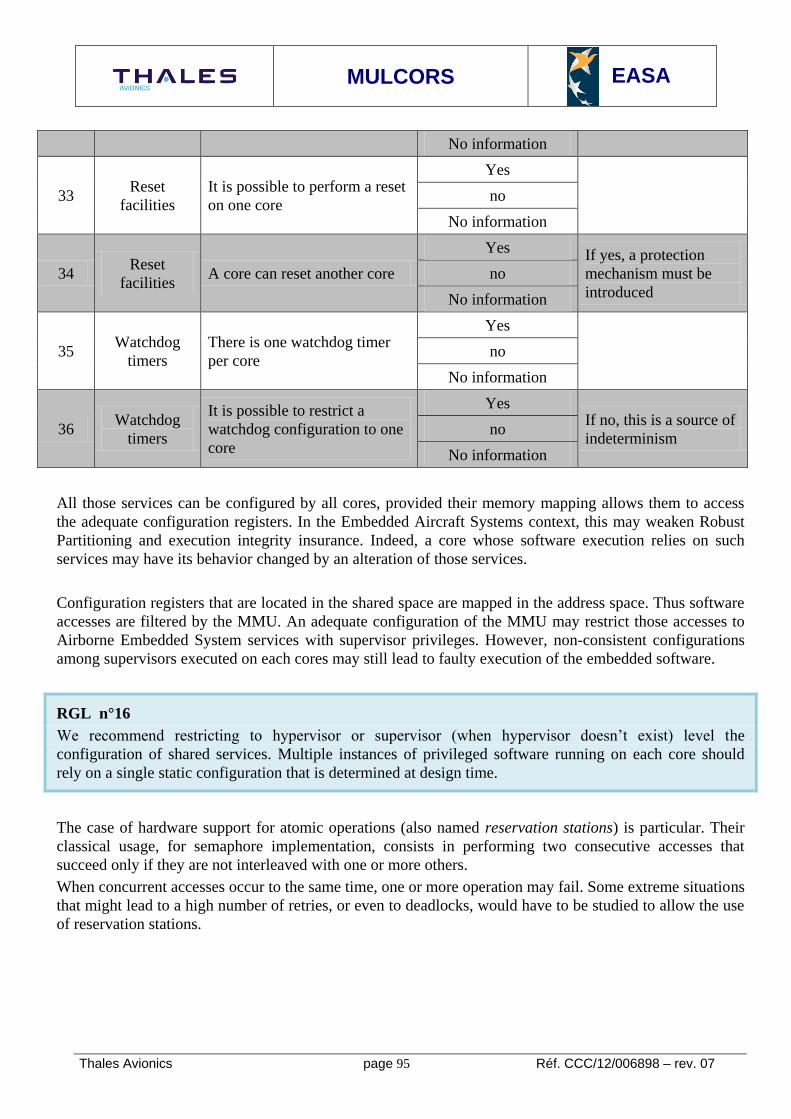
MULCORS
EASA
Thales Avionics page 95 Réf. CCC/12/006898 – rev. 07
No information
33 Reset
facilities
It is possible to perform a reset
on one core
Yes
no
No information
34 Reset
facilities A core can reset another core
Yes If yes, a protection
mechanism must be
introduced
no
No information
35 Watchdog
timers
There is one watchdog timer
per core
Yes
no
No information
36 Watchdog
timers
It is possible to restrict a
watchdog configuration to one
core
Yes If no, this is a source of
indeterminism no
No information
All those services can be configured by all cores, provided their memory mapping allows them to access
the adequate configuration registers. In the Embedded Aircraft Systems context, this may weaken Robust
Partitioning and execution integrity insurance. Indeed, a core whose software execution relies on such
services may have its behavior changed by an alteration of those services.
Configuration registers that are located in the shared space are mapped in the address space. Thus software
accesses are filtered by the MMU. An adequate configuration of the MMU may restrict those accesses to
Airborne Embedded System services with supervisor privileges. However, non-consistent configurations
among supervisors executed on each cores may still lead to faulty execution of the embedded software.
RGL n°16
We recommend restricting to hypervisor or supervisor (when hypervisor doesn’t exist) level the
configuration of shared services. Multiple instances of privileged software running on each core should
rely on a single static configuration that is determined at design time.
The case of hardware support for atomic operations (also named reservation stations) is particular. Their
classical usage, for semaphore implementation, consists in performing two consecutive accesses that
succeed only if they are not interleaved with one or more others.
When concurrent accesses occur to the same time, one or more operation may fail. Some extreme situations
that might lead to a high number of retries, or even to deadlocks, would have to be studied to allow the use
of reservation stations.

MULCORS
EASA
Thales Avionics page 96 Réf. CCC/12/006898 – rev. 07
RGL n°17
We recommend that implementation of semaphores should take in account potential deadlocks due to
shared reservation stations.
Corresponding selection criteria 9.4.2.6..2
Criteria Sub-criteria Weight
for
DAL
A/B
Weight
for
DAL
C/D
Observations
It is possible to
restrict shared
services
configuration to
a high privilege
level
Accesses to the shared
interrupt controller,
PLL32
, shared watchdog,
power sources... can be
restricted to the
supervisor/hypervisor
without impacting
accesses to other
peripherals
3 2 An adequate configuration of the
MMU may provide such
restriction. Yet the mapping
should not entail access
restrictions on other peripherals.
See RGL n°16
One core cannot reset
another core at user
privilege level
3 3 Reset signals can often be raised
following various events. Even if
explicit resets can be restricted to
privileged software, it shall be
determined whether some errors
or events triggered by user-level
operations might entail reset
signals.
See RGL n°18
Weights: 1: informative
2: Nice to have
3: Mandatory
RGL n°18
We recommend, in multi-core configurations, not to authorize one core, under USER privilege level, to be
able to reset another core. Only Hypervisor or Supervisor (if hypervisor doesn’t exist) have the
authorization to perform this reset.
32
PLL : Phase Locked Loop
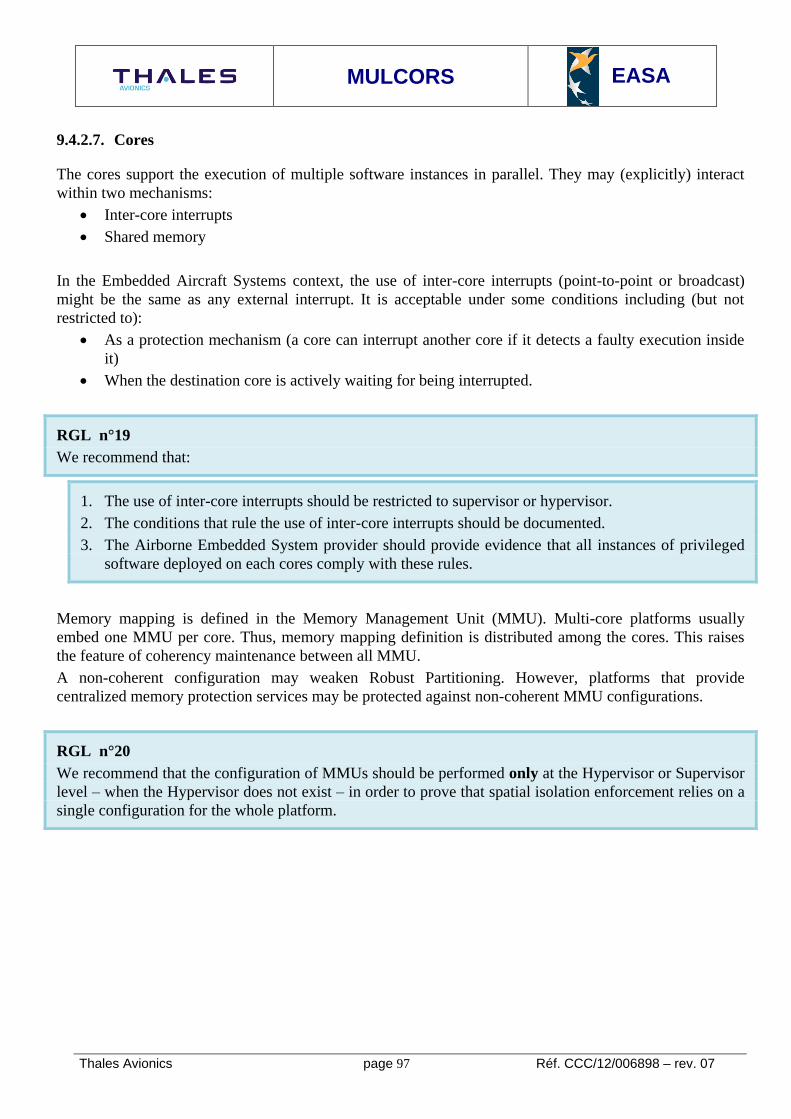
MULCORS
EASA
Thales Avionics page 97 Réf. CCC/12/006898 – rev. 07
9.4.2.7. Cores
The cores support the execution of multiple software instances in parallel. They may (explicitly) interact
within two mechanisms:
Inter-core interrupts
Shared memory
In the Embedded Aircraft Systems context, the use of inter-core interrupts (point-to-point or broadcast)
might be the same as any external interrupt. It is acceptable under some conditions including (but not
restricted to):
As a protection mechanism (a core can interrupt another core if it detects a faulty execution inside
it)
When the destination core is actively waiting for being interrupted.
RGL n°19
We recommend that:
1. The use of inter-core interrupts should be restricted to supervisor or hypervisor.
2. The conditions that rule the use of inter-core interrupts should be documented.
3. The Airborne Embedded System provider should provide evidence that all instances of privileged
software deployed on each cores comply with these rules.
Memory mapping is defined in the Memory Management Unit (MMU). Multi-core platforms usually
embed one MMU per core. Thus, memory mapping definition is distributed among the cores. This raises
the feature of coherency maintenance between all MMU.
A non-coherent configuration may weaken Robust Partitioning. However, platforms that provide
centralized memory protection services may be protected against non-coherent MMU configurations.
RGL n°20
We recommend that the configuration of MMUs should be performed only at the Hypervisor or Supervisor
level – when the Hypervisor does not exist – in order to prove that spatial isolation enforcement relies on a
single configuration for the whole platform.

MULCORS
EASA
Thales Avionics page 98 Réf. CCC/12/006898 – rev. 07
Corresponding selection criteria 9.4.2.7..1
Criteria Sub-criteria Weight
for
DAL
A/B
Weight
for
DAL
C/D
Observations
Inter-core
interrupts
emission can be
controlled
Inter-core interrupts
generation can be
restricted to a supervisor
or a hypervisor
3 3 This criterion is mandatory to
prevent inter-core interrupts
from being emitted by the
airborne software in an
unpredictable way
See RGL n°19
Memory
mapping can be
protected against
non-coherent
configurations
There is a centralized
service of memory
protection unit
2 1 Having a centralized protection
mitigates the risk of non-
coherent configuration of
distributer memory protection
mechanisms.
See RGL n°20
Weights: 1: informative 2: Nice to have 3: Mandatory
9.4.2.8. Peripherals
Several features dealing with shared peripherals have to be considered. We distinguish features concerning
the main memory from those concerning I/O.
Sharing the main memory means sharing the physical storage resources and the memory controllers. The
storage resource can be partitioned when necessary: disjoint memory areas can be allocated to each core
(this is space partitioning). We do not consider this feature in this section. Sharing accesses to the memory
controllers may in some cases increase the timing variability of a transaction with a factor higher than the
number of accessing masters (see (Moscibroda & Mutlu, 2007) for an illustration: on a dual-core platform,
a task is slow downed with a factor of 2.9 while the concurrent task is not).
These side-effects are due to the internal structure of a DDR. It contains several banks, each bank having
internal read/write buffers, internal scheduling optimized for contiguous read/write transactions. Incoming
transactions have been interleaved in the interconnect. Thus, contiguous accesses sent by a core may not be
contiguously serviced inside the memory controller. This phenomenon cannot be controlled by the
software. Thus its worst case timing variability has to be determined and applied for each memory
transaction.

MULCORS
EASA
Thales Avionics page 99 Réf. CCC/12/006898 – rev. 07
RGL n°21
We recommend that the Interconnect Usage Domain should specify atomic access patterns to the main
memory to provide tighter bounds on timing variability of memory transactions,.
We recommend that Worst Case Response Time should be determined for these patterns and Memory
transactions should be encapsulated inside them.
Shared I/O features dealing with configuration are similar to shared services configuration. Additional
features occur when the cores concurrently perform the following actions:
Access simultaneously read and/or write buffers. Here classic rules of time and space partitioning
can apply: storage areas have to be partitioned with some component controlling their access, and
when it is not possible ensure that concurrent accesses will occur in disjoint time windows.
Initiate specific protocols operations. Here, uninterrupted access is required during the protocol
execution to be able to fulfill correctly the concerned protocol.
Like shared services, concurrent accesses to shared I/O may occur simultaneously from different cores. Yet
their use is more complex then configuration of shared services. Some I/O are accessed according to a
protocol, others are accessed from a read and/or write buffer. Thus atomic access patterns have to be
ensured.
RGL n°22
We recommend that accesses to shared I/O dealing with configuration should be restricted to the
Hypervisor or Supervisor level – if the Hypervisor level does not exists – access patterns to these I/O
should be documented in the Interconnect Usage Domain.
Classically, shared I/O’s accesses are managed by the supervisor or the hypervisor. The three existing
management methods are:
I/O emulation. On each core, the supervisor/hypervisor emulates a virtualized I/O interface. It is in
charge of propagating I/O accesses to the physical I/O. This interface may be a simple read/write
buffer (the supervisor/hypervisor implements in its own driver the corresponding protocols), or a
complete I/O (the supervisor/hypervisor leaves I/O management to the Airborne Software)
I/O direct access. On each core, the supervisor/hypervisor configures the MMU to enable direct I/O
accesses. The supervisor/hypervisor does not intercept further accesses.
I/O manager core. One core is dedicated to I/O transactions. For the remaining cores, I/O
transactions are encapsulated inside inter-core messages that are propagated through a
communication service.
Today’s experience in shared I/O management is not sufficient to recommend one method rather than the
two others for an Embedded Aircraft Systems usage.

MULCORS
EASA
Thales Avionics page 100 Réf. CCC/12/006898 – rev. 07
Corresponding selection criteria 9.4.2.8..1
Criteria Sub-criteria Weight
for
DAL
A/B
Weight
for
DAL
C/D
Observations
Memory
mapping allows
I/O per I/O
isolation
All I/O may be accessed
in different pages so that
I/O management can be
partitioned by the MMU
2 1 It is preferable to have a control
I/O per I/O.
Yet this is not mandatory since
I/O control is provided by
platform software.
Weights: 1: informative
2: Nice to have
3: Mandatory

MULCORS
EASA
Thales Avionics page 101 Réf. CCC/12/006898 – rev. 07
9.5. SOFTWARE ASPECTS
This chapter deals with tasks 7 and 8
9.5.1. Summary of task 7
In combination with the steps listed above, identify and analyze the software architectures that may be used
in combination with the hardware of each processor group and, if possible, classify those software
architectures into groups.
Criteria for this grouping might include such factors as whether symmetric, asymmetric or ‘bare-metal’
multi-processing would be used, whether there are suitable certifiable operating systems that may be
acquired and incorporated to execute on the processor and for which types of processing the processors
would be best suited.
The study shall identify whether there are particular ways to allocate tasks or parts of tasks to the processor
cores that would be most safe and effective for each type of processor and / or operating system, e.g.
allocating a single critical task to each processor.
9.5.2. Summary of task 8
Identify the methods, tools, languages and operating systems that would be most suitable for specification,
development and implementation of safety-critical software to execute in parallel with robust partitioning
on the representative processors and any software / COTS IP that they include.
This chapter deals with multi-cores features related to software execution on a multi-core processor. We
focus on Airborne Software in general and platform software (that is granted the supervisor and/or
hypervisor privileges) in the case of partitioned systems, especially IMA systems.
9.5.3. Airborne Software deployment on a multi-core platform
9.5.3.1. Airborne Software execution on several cores
Executing an Airborne Software on several cores on a multi-core platform is possible when it is
implemented under parallel schemes. Two models are possible:
Multitasking: The Airborne Software is decomposed in parallelizable tasks that will be activated by
a scheduler. This model is implemented in all operating systems that support the execution of
several Airborne Software.
Client-Server: Some services are implemented in servers that are deployed on specific cores. The
Airborne Software, executed on another core, requests those servers as a client. This model is
classically used in distributed Airborne Software and relies on Remote Procedure Calls techniques.
Intergiciels like CORBA propose services to ease the development of such Airborne Software, for
instance messages encapsulation to facilitate method and arguments passing. Some of them have
been designed to provide real-time performances.

MULCORS
EASA
Thales Avionics page 102 Réf. CCC/12/006898 – rev. 07
Multitasks scheduling features 9.5.3.1..1
The classic approach for a multitasked system is the hierarchical model based on processes (or partition)
and threads (we use UNIX terminology. In ARINC 653, the equivalent components are partitions and
processes). Processes (or partitions) are executed from isolated memory areas. Inside a process, one or
more threads are executed in the same address space. The use of threads is quite flexible in parallel
programming because it enables the definition of shared objects that can directly be accessed by the
different threads.
For simplicity, we talk about tasks rather than processes and threads. Usually, parallel programming
models include two kinds of tasks: periodic and sporadic (with a minimal inter-arrival time).
Processes and threads activation depends on a scheduling algorithm. One can read the following survey on
scheduling algorithms for single and multi-core processors: (Blake, Dreslinski, & Mudge, 2009). Like
single-core algorithms, multi-core ones have to solve the Priority Problem. That means they have to decide
in which order and when tasks will be executed. Moreover, multi-core scheduling algorithms have to solve
the Allocation Problem. That means they have to decide on which core a task will be executed. This leads
to the definition of two categories of algorithms: global and partitioned, respectively allowing or not
migrations of tasks among the cores.
To be acceptable for an Embedded Aircraft Systems system, a scheduling algorithm shall verify the
following properties:
Feasibility: There shall be a scheduling test that depends on the Worst Case Execution Time, the
period (if any) and the deadline of each task.
Predictability: The Response Time of the set of tasks (i.e. the time in which all tasks will be
scheduled) does not increase if the execution time of one task decreases
The second property is critical. Indeed, it ensures that a set of tasks whose schedule has been validated with
their estimated WCET will meet its deadline considering the real execution time of tasks.
Usually, pre-emptive and priority based scheduling algorithms (for instance Rate Monotonic, or Earliest
Deadline First) are preferred for single-core processors because they check the previous properties, their
implementation is easier and worst case performance can easily be computed. For instance, ARINC 653
recommends such an algorithm to schedule processes inside a partition. Cooperative programming models
and associated scheduling algorithms may also be used as long as the system does not require robust
partitioning. Indeed cooperative programming introduces many functional dependencies between tasks that
are not compatible with robust partitioning enforcement.
It has been proven that pre-emptive and fixed priority multi-core scheduling algorithms still verify those
properties, for instance Global Rate Monotonic or Global Deadline Monotonic. However this is no longer
the case for dynamic priority algorithms, such as Global Earliest Deadline First. In the case of partitioned
algorithms, the problem remains equivalent to single-core algorithms, thus pre-emptive and priority based
algorithms are predictable.

MULCORS
EASA
Thales Avionics page 103 Réf. CCC/12/006898 – rev. 07
Global scheduling algorithms have an advantage over partitioned algorithms: they are more efficient.
Indeed, all task sets schedulable under a partitioned algorithm will be schedulable by the equivalent global
algorithm. The opposite is not true. Moreover, global algorithms save the cost of a static allocation that
may be a NP-hard problem. However, they have drawbacks. They entail task migrations whose costs have
to be bounded, and they manipulate larger data structures whose cost may be prohibitive.
RGL n°23
We recommend the use of partitioned scheduling algorithms and static allocation of tasks to cores that will
be decided at Design Time and forbidden at Run Time.
Airborne Software migration from single-core to multi-core platforms 9.5.3.1..2
When porting multitasked Airborne Software from a single-core to a multi-core platform, the Airborne
Software developer has to be sure that:
The Airborne Software execution will still be correct
A Worst Case Execution Time will be calculated for each task or process.
It can also be noticed that multitasked airborne software may not be efficiently executed on a multi-core
platform if its tasks have dependencies requiring a specific execution order.
Concerning the first requirement, care has to be taken if the Airborne Software is implemented within a
cooperative tasks model. Indeed, such an implementation usually removes protections in critical sections
accesses. In a sequential execution, this is correct: during a critical section, no pre-emption will occur if the
developer does not explicitly write it. However, in a multi-core execution, this critical section might be
executed in parallel by different tasks, resulting in an erroneous execution. Yet the execution would be
correct if the critical section was protected by a semaphore.
RGL n°24
We recommend, when Airborne Software is a multitasked one that critical sections should be explicitly
protected by semaphores in case of cooperative programming.
Moreover, the execution of multitasked Airborne Software on several cores may require additional
mechanisms such as cache coherency. The use of such mechanisms might not be compatible with
restrictions imposed on the Platform or Equipment usage.
RGL n°25
We recommend that multitasked Airborne Software design should minimize the use of cache coherency
mechanisms in order to be compliant with the Interconnect Usage Domain.

MULCORS
EASA
Thales Avionics page 104 Réf. CCC/12/006898 – rev. 07
Features regarding the second requirement will be covered in part 9.8 dealing with tools for processing
Worst Case Execution Time calculus on multi-core platforms.
Partitioned system features 9.5.3.1..3
This section is a generic one not only focusing on IMA (Integrated Modular Avionics), this section
addresses all systems whether partitioning is implemented using ARINC653 Operating Systems or not.
When we address IMA Avionics Embedded Systems, we address partitioning regarding ARINC653
terminology: Airborne Software is composed of one or more partitions which are composed of one or more
processes. Processes are executed in the same address space among one partition. Function suppliers are in
charge of developing partitions. The Operating System provider (it may be the Platform Provider himself)
is in charge of developing the Platform software.
9.5.3.1..3.1 Components evolution to take benefit of multi-
core platforms
This section presents our view (as a Avionics Embedded
System supplier) of partitioned Avionics module adaptation
(see Figure 13) to take benefit of the introduction of multi-
core processors in IMA Platforms
Current designs for Airborne Software should not change, or
with minor modifications (i.e. comparable to a migration to
another single-core platform). Indeed, a large change in this
concept would represent a large design and implementation
effort. In addition, the trend would be to promote reuse of
previously SW Airborne Software, while keeping up backward
compatibility.
From the Avionics Embedded System supplier’s point of view, the most “flexible” component is the
integration software layer. At this level of abstraction, there are possible designs:
A single OS instance shared among all the cores
A private OS instance per core
A virtualization layer hosting several operating systems in dedicated virtual machines.
Today, experience gained in multi-core architecture is deemed not sufficient to allow determination of
which design strategy is the best suited for avionics Airborne Software.
Figure 13: HW/SW Architecture for a future multicore IMA module

MULCORS
EASA
Thales Avionics page 105 Réf. CCC/12/006898 – rev. 07
9.5.3.1..3.2 Deployment of partitions
One stake in the introduction of multi-core in partitioned Embedded Aircraft Systems is the mastering of
the parallel execution of code on different cores. This parallelism can occur at two level of abstraction:
Intra-partition parallelism. The extreme scenario occurs when one partition is activated on all cores
and has an exclusive access to platform resources. This is called the Symmetrical Multi-processing
(SMP).
Inter-partition parallelism. The extreme scenario occurs when each partition are activated on one
core with true parallelism between partitions. This is called the Asymmetrical Multi-processing
(AMP).
There is a third case named Bound Multi-processing which consist in having a single instantiation of an
OS managing all Cores simultaneously, but each Airborne Software application is locked to a specific
Core. We don’t address this case in this document: it can be considered as a subset of the previous ones.
9.5.3.1..3.3 Symmetrical Multi-processing
A Symmetrical Multi-Processing (SMP) deployment means that partitions are activated on each core (see
Figure 14). Inside a partition, processes may be executed in parallel on different cores. Integrity and WCET
features covered in part 9.5.3.1 are valid in this context. There may be inter-processes conflicts when
accessing to the shared resources. This does not impact time and space partitioning (because those conflicts
occur inside the same partition), but it brings additional constraints on the function suppliers
SMP partitions deployment has the following good properties:
Respect of ARINC 653 time and space partitioning requirement is possible without any
modifications to the guidelines.
There is no true parallelism between partitions.
Some Airborne Software applications are, because of their architectures, good candidates for parallel
implementation. Examples of such airborne software applications are Flight Management Systems or
Signal Processing applications. However, this is not the case for many legacy airborne software
applications running on Embedded Airborne Systems such as utilities. For those applications, backward
compatibility seems possible with minor changes, but highly inefficient.
Figure 14: Example of a SMP deployment of partitions

MULCORS
EASA
Thales Avionics page 106 Réf. CCC/12/006898 – rev. 07
9.5.3.1..3.4 Asymmetrical Multi-processing
An Asymmetrical Multi-Processing (AMP) deployment means that one partition is deployed on a single
core in parallel with other partitions (see Figure 15).Thus scheduling of processes inside a partition is
sequential
Remark: for IMA, ARINC 653 guidelines are still valid
Good properties of an AMP deployment are:
It does not change the model of sequential partitions that are executed inside a Single core Avionics
Embedded System. Thus the backward compatibility of legacy Airborne Software is closer to the
existing single-core configurations. The precedence rules related to inter-partition communications
(e.g. partition 1 shall finish before partition 2 starts to provide valid data…) do not impact
performance.
It scales with the increase of the number of cores
Remark, for IMA Avionics Embedded System
ARINC 653 space partitioning requested inside an API context can be ensured between all Cores.
ARINC 653 time partitioning is ensured between partitions deployed on the same core inside an
API context.
However, Robust Partitioning has to be ensured between Cores. As presented in the section 9.4.2.3..6, the
presence of eventual uncontrolled inter-core conflicts may not be compatible with Robust Partitioning
enforcement at the highest level of criticality.
9.5.3.1..3.5 AMP-SMP-BMP selection
Today's experience in multi-core for Embedded Aircraft Systems does not seem sufficient to recommend a
deployment rather than others. The following table gives a comparison of those approaches. The choice of
the approach is left to the platform provider.
Figure 15: Example of an AMP deployment of partitions

MULCORS
EASA
Thales Avionics page 107 Réf. CCC/12/006898 – rev. 07
AMP
It can be noticed that the an AMP approach offers more compatibility with existing single-core
avionic Airborne Software,
AMP offers a better performance characteristics close to already existing systems, but presents
some difficulties in the demonstration of robust partitioning,
SMP
SMP approach needs to be taken into account by Airborne Software developer to take benefit from
platform.
SMP offers a better capability to implement robust partitioning, but at the price of lower
performance and less freedom to implement modifications
Criterion SMP AMP BMP
Reliability
Potential decrease due
to a higher level of
integration
Increase if it is possible
to recover from a failure
inside a core by
restarting the concerned
core rather than the
whole platform
Same advantages and
limitations as SMP and
AMP
Robust Partitioning
insurance
Time and Space
Partitioning (and thus
Robust Partitioning) can
be ensured. Partition
switching requires inter-
core synchronization.
Partition switching
timing upper bound has
to be determined
Space partitioning can
be implemented.
However, time
partitioning is not
enforced anymore
between partitions
executed simultaneously
on different cores
This approach requires
Robust Partitioning to
be ensured
Same problem as AMP
Performance gain
on partitions
(compared to a
single-core similar
platform)
Significant performance
increase for partitions
that can be parallelized
(e.g. Flight
Management System)
No performance
increase inside one
partition
Depending on the
number of cores
executing the partition
Airborne Software
Integration
Slight increase of
application integration
because of individual
performance increase
Significant increase of
Airborne Software
integration
Increase of Airborne
Software integration
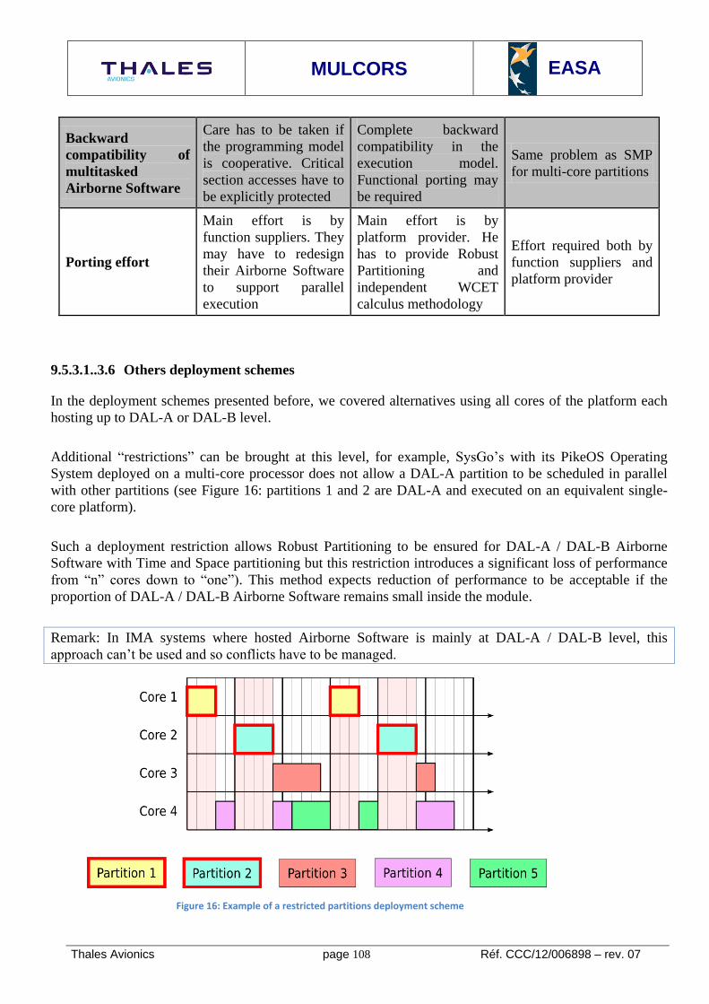
MULCORS
EASA
Thales Avionics page 108 Réf. CCC/12/006898 – rev. 07
Backward
compatibility of
multitasked
Airborne Software
Care has to be taken if
the programming model
is cooperative. Critical
section accesses have to
be explicitly protected
Complete backward
compatibility in the
execution model.
Functional porting may
be required
Same problem as SMP
for multi-core partitions
Porting effort
Main effort is by
function suppliers. They
may have to redesign
their Airborne Software
to support parallel
execution
Main effort is by
platform provider. He
has to provide Robust
Partitioning and
independent WCET
calculus methodology
Effort required both by
function suppliers and
platform provider
9.5.3.1..3.6 Others deployment schemes
In the deployment schemes presented before, we covered alternatives using all cores of the platform each
hosting up to DAL-A or DAL-B level.
Additional “restrictions” can be brought at this level, for example, SysGo’s with its PikeOS Operating
System deployed on a multi-core processor does not allow a DAL-A partition to be scheduled in parallel
with other partitions (see Figure 16: partitions 1 and 2 are DAL-A and executed on an equivalent single-
core platform).
Such a deployment restriction allows Robust Partitioning to be ensured for DAL-A / DAL-B Airborne
Software with Time and Space partitioning but this restriction introduces a significant loss of performance
from “n” cores down to “one”). This method expects reduction of performance to be acceptable if the
proportion of DAL-A / DAL-B Airborne Software remains small inside the module.
Remark: In IMA systems where hosted Airborne Software is mainly at DAL-A / DAL-B level, this
approach can’t be used and so conflicts have to be managed.
Figure 16: Example of a restricted partitions deployment scheme

MULCORS
EASA
Thales Avionics page 109 Réf. CCC/12/006898 – rev. 07
Today’s experience in Embedded Aircraft Systems seems not be enough to state whether such restrictions
are necessary or if all cores may be used whatever the level of criticality.
9.5.3.2. Airborne Equipment software features
Airborne Equipment software usually refers to an operating system and/or to a hypervisor whose integrity
is protected by a dedicated privilege level. The platform provider may not be the Airborne Equipment
software developer (he may integrate existing COTS solutions) but he is supposed to have a sufficient
knowledge on its behavior and its architecture.
RGL n°26
We recommend, if SMP mode is selected by the platform provider for the Operating System that processes,
threads or tasks are statically allocated to cores to achieve determinism and repeatability.
RGL n°27
We recommend, if the Avionics Software Behavior is not known by the platform supplier and AMP mode
for the Operating System is selected, the use of a Hypervisor to master the behavior of the Interconnect
Usage Domain.
Architectural concerns 9.5.3.2..1
Features concerning the architecture of Platform or Equipment software are close to ones concerning
partition deployment on a multi-core platform. They depend on the cores on which the platform software is
deployed.
9.5.3.2..1.1 Symmetrical Multi Processing
We talk about a symmetric architecture (also called Symmetric Multi-Processing-SMP – In the literature)
when a single instance of the platform software is deployed on
all cores (see Figure 17). It can be noticed that the notion of
“deployed on all cores” may be ambiguous. For instance, the
same service may be executed locally on each core (i.e. from a
private cache), even with private data. Other services may be
hosted by a dedicated core, and service requests occur through
inter-core communication.
The notion of symmetric architecture for privileged software
can be more precisely defined as follows:
SMP privileged software has all its services executed under a
non-disjoint execution environment on each core.
Figure 17: Example of symmetrical OS deployment (source: Freescale white paper on SMP/AMP/BMP)

MULCORS
EASA
Thales Avionics page 110 Réf. CCC/12/006898 – rev. 07
An execution environment refers to virtual memory mapping on physical memory. For instance, we can
consider two cores A and B. The privileged software may define local (and disjoint) memory pages inside
A and B, and execute some services inside such pages. Thus, the services on core A are actually isolated
from the duplicated services on core B. However, core B shares the environment under which core A
defined its memory mapping. Thus it has access to the information used by core A to define its memory
mapping.
9.5.3.2..1.2 Asymmetrical Multi Processing
We talk about asymmetric architectures (or Asymmetrical Multi Processing -AMP) when several
independent instances of privileged software are executed
on different cores (for instance, see Figure 18).
Each privileged software instance (operating system or
hypervisor) is executed in its own context. That means on
one core, the memory mapping is not visible from the other
cores. This deployment allows the reuse of single-core
operating systems with minimal modifications. Care has to
be taken at the boot sequence because one core will be
started as master and will be in charge of performing
platform early initialization and starting its fellows.
Moreover, I/O features may occur when shared I/O’s are
accessed concurrently by different operating systems.
Those features are covered in the next section as they are
classically resolved through I/O virtualization.
Figure 18: Example of asymmetric architecture (source: Freescale white paper SMP-AMP-BMP)

MULCORS
EASA
Thales Avionics page 111 Réf. CCC/12/006898 – rev. 07
9.5.4. Mitigation means
This chapter deals with task 5
9.5.4.1. Summary of task 5
In each case where a component or feature is not suitable for use in safety-critical airborne systems,
identify whether or not there are any feasible measures that might be used to mitigate the particular
negative effect by means of, for example, architectural mitigation, work-around, disabling the feature
concerned, imposing rules or limitations on the use of the feature concerned or any other means that the
study may identify.
9.5.4.2. Mitigation Means Analysis
There are quite a few features in the design of COTS multi-core processors that must be mastered to allow
use of such technology in safety-critical systems. These include: variability of execution time, service
and/or transaction conflicts, core interconnect switches, cache architecture structures, shared services,
inter-core interrupts, access to peripherals, programming languages. These features are listed in the
following table, together with suggested recommendations on mitigation means that can be used. This does
not preclude use of the actual solution that might be developed by the computing platform designer to cater
for each of those features.
COTS Multi-Core Features Mitigation means Comments
Variability of Exec. Time WCET strategy for assessment,
measurement and continuous
monitoring.
Tools may be used for
measurement.
Service/transaction conflicts Software-controlled scheduling of tasks
or processes.
Cores interconnect switch Interconnect Usage Domain Definition.
Cache architecture structure Multi-core-related cache management
(e.g. one cache way per core or
restrictions on the use of shared caches).
Cache consistency verified by trusted
and privileged software.
Similar approach can be used
for the control of MMU
consistency.
Shared services Similar to Airborne Software
Programming Interface (APIs), services
must be offered via a trusted and
privileged software.
Inter-core interrupts Accept interrupt only when expected
(rules to implement wait-for-interrupt)
or restrictions on the use of inter-

MULCORS
EASA
Thales Avionics page 112 Réf. CCC/12/006898 – rev. 07
processors interrupts.
Access to peripherals Shared I/O’s configuration and/or shared
memory space should be allocated by
trusted and privileged software, either
directly or via configuration controlled
configuration tables.
Programming languages Determine adequate strategy for multi-
processing programming (e.g. pre-
emptive versus co-operative).
One of the principal features of multi-core processors that have a tremendous impact and consequence for
their use in safety-critical airborne systems is the increased variability in the execution time, when
Airborne Software is run directly on the multi-core architecture. The negative effect of this feature is the
inability to demonstrate a stable WCET, which can be relied upon for certification of runtime Airborne
Software. The mitigation means that are suggested to handle such difficulties are briefly exposed below.
This is mainly based on a straightforward step-by-step approach to WCET determination.
In the case of single-core [mono]-processors, their internal complexity of cache architecture in particular
(including multiple levels of caches), and built-in parallelism (e.g. instruction execution based on pipelined
architecture), already led to difficulties in the determination of a formal WCET for software running on
such processors. However, measurements combined with assessments, relying also on architecture
modeling, have allowed a demonstration of WCET to be achieved with an upper bound limit value with an
acceptable level of confidence.
For Multi-core processors, this feature is a bit more stringent, hence a more “relative” WCET should be at
least achieved, i.e. using the same basic approach as for mono-core processors, possibly complemented by
additional measurements, including under abnormal conditions (interrupt triggering, simulated failures or
reset cases) to allow an assessment of the robustness of such measurements.
The following is suggested as mitigation means when determinism, hence an absolute WCET is not
achievable. The recommended approach consists of four main axes that must be addressed:
9.5.4.3. Time jitter ratio to total execution time
A Channel Interference Analysis should be performed in any case whether the multi-core platform is
destined to host single or multiple Airborne Software.
This interference channel analysis should allow determination of a maximum execution time jitter, based
on:
A theoretical analysis of available information (from device manufacturer and on the
implementation in the architecture), or
Via measurements based on selected benchmarks implementing worst case perturbations regarding
expected jitter, or

MULCORS
EASA
Thales Avionics page 113 Réf. CCC/12/006898 – rev. 07
A combination of the two methods above.
As those methods are based on engineering judgment, additional margins should be added to this jitter
ratio.
9.5.4.4. Airborne Software WCET evaluation
WCET for each Airborne Software could be evaluated as on a mono-processor in a first step, and corrected
using above jitter ratio including margins. Validation of final WCET value could be done by measurement
in the presence of other selected benchmarks implementing worst case perturbations on other processors
(defined according to time jitter ratio).
9.5.4.5. Monitoring during real-time execution
Execution time should be monitored (e.g. using built-in checks that execution time does not exceed WCET,
and records of minimum and maximum values).
This monitoring could be limited to the critical paths identified for an Airborne Software application,
providing that background tasks are assessed as not being affected by jitter. This run time monitoring
comes in addition to the partition switching code that insures partitioning. It has two main objectives:
Firstly during the development phase to collect data relative to the actual execution time as
observed. This should lead to complementary validation of the jitter ratio determined above, but
also to identify scenarios that were not correctly covered by analysis, and to implement
corrections to the WCET analysis and jitter ratio whenever necessary.
Secondly, during run time operation, once the jitter ratio is considered stable (i.e. sufficiently
bounded with acceptable margins) to implement detection mechanisms able to stop processor
execution (platform reset) of Airborne Software (software reset) when an Airborne Software
application exceeds the target limit.
9.5.4.6. Airborne Software robustness
As the above described method is largely based on engineering judgment, it might be considered that
execution time jitter in some remote cases could cause the WCET to be exceeded, then leading to
unacceptable spurious resets (platform or Airborne Software). A general strategy and principle of airborne
software robustness versus resets should be implemented.

MULCORS
EASA
Thales Avionics page 114 Réf. CCC/12/006898 – rev. 07
9.6. FAILURE MITIGATION MEANS
This chapter deals with task 10
9.6.1. Summary of task 10
Examine whether the architectures of multi-core processors may affect the ability of a system to detect
failures within the processors or their associated hardware and the ability of the system to make it safe, to
re-start and recover in the event of a failure being detected.
The study shall determine which multi-core processors incorporate features such as memory management
units and detection of division by zero and ensure that watchdog timers can be incorporated. The study
shall identify which kinds of failure detection are possible, whether the processors incorporate any form of
exception handling and what the response of the processor is to error detection, e.g. shutting down the
affected software partition, the processing core, the entire processor or any other means.
9.6.2. Mitigation means
The architecture of multi-core processors is organized around the Interconnect.
In association with the temporal Interconnect behavior defined through the Interconnect Usage Domain, it
is expected that the Interconnect shall not jeopardize the intrinsic processor detection of abnormal events
and also shall not propagate any abnormal events initiated by a processor to the others or a group of others
attached to the same Interconnect.
The generation of exceptions and the recovery actions shall be considered at the fault containment area
level: partition, processor, I/O.
The Interconnect shall act as a fault container with respect to each processor including their I/O
management. The notion of partitioning has also to be extended down to the I/O interfaces with associated
fault detection.
RGL n°28
We recommend, for mitigation means, that the Interconnect Usage Domain should be defined to act as a
fault container between cores.

MULCORS
EASA
Thales Avionics page 115 Réf. CCC/12/006898 – rev. 07
9.7. COTS RELATED FEATURES
This chapter deals with task 11
9.7.1. Summary of task 11
Analyze the processor architectures and examine any problems or processor errata that have already been
found to determine whether multi-core processors in general or particular types of them might suffer from
more frequent failures or different or more widespread types of failures than the current single core
processors. This shall include failures due to radiation induced effects such as SEU (single event upsets),
whether such effects would be detectable and whether the processors incorporate any means to detect such
events and correct the errors produced.
9.7.2. COTS related features analysis
The following major concerns are determining factors for the selection of complex and highly complex
COTS processors for use in Embedded Aircraft Systems. The concept of Systems On Chip (SoC), which
includes either microcontrollers and multi-core processors, together with heterogeneous peripherals, has
been known over the past few years. Those concepts were made possible thanks to high-density integration
of transistors on a single chip. From Moore's law the capability of technology in terms of number of
transistors integration is to double every 12 to 18 months.
Figure 19: an example of technology evolution, up to 2022 (Source: INTEL)

MULCORS
EASA
Thales Avionics page 116 Réf. CCC/12/006898 – rev. 07
The benefits of such technology are to integrate more and more transistors into smaller silicon areas, while
achieving better performance and low-power consumption. An illustration is the Deep [and Very Deep]
Sub Micron (DSM) CMOS technology used for multi-core processors. Deep submicron technology is using
transistors of smaller size and faster switching rates. Transistor sizes, see Figure 19, down to 35nm, 25nm,
18nm, 13nm and below are envisioned, compared to the currently used sizes of 90nm and 45nm. However
a number of features and challenges arose with such technology:
Low-power design and temperature susceptibility,
Better Signal/Power Integrity and quality,
Higher Density and Design Complexity,
Packaging and testing of large chips,
Design to Cost optimal approach,
Device parameter variability due to leakage
To date, a conservative approach in the design of embedded complex and critical real-time Embedded
Aircraft Systems was to use complex to highly-complex micro-processors and microcontrollers, so-called
SoCs, without further consideration of technology concerns. However various aspects should be addressed
before going farther toward DSM with technologies down to lower sizes. Two examples are addressed
below:
9.7.2.1. Electro-migration
This phenomenon tends to reduce the useful life duration of an SoC (figures for 90nm technology, when
used continuously at maximum temperature range (105°C) and frequency range, are around 15 years, for
45nm it can be reduced to about 10 years, and down to less than five years for consumer grade quality
below 28 nm).
This becomes insufficient for their use in Embedded Aircraft Systems for which the required reliability
figures would be more of the order of 15 years. For other reasons (procurement costs, components
obsolescence and newly required functions), Embedded Aircraft Systems renewal for on-board typical
commercial aircraft is of the order of every 10 years, which would make 90, 45, 32 nm technology still
compatible with such designs, analysis in progress for 28 nm.
RGL n°29
We recommend, for multi-core processor selection, that selection criteria should include Intrinsic
Reliability data delivered by the component manufacturer.
9.7.2.2. Single Event Effects
Sensitivity to atmospheric radiation such as Single Event Upsets (SEUs) and Multiple Bit Upsets (MBUs)
is a serious concern for embedded Airborne Software. Experience has shown that for 90nm or 45 nm
technologies, no significant degradation is observed. Component manufacturers are currently testing down
to 28 nm technology. First results are expected during year 2013. Error Correcting Codes (ECC) have been

MULCORS
EASA
Thales Avionics page 117 Réf. CCC/12/006898 – rev. 07
implemented in the design made with Single-core microprocessors, including relying upon ECC internal to
the COTS device. Some COTS multi-core processors now feature ECC mechanisms inside.
However, it is anticipated that access to information from manufacturers on internal memory architecture
with or without ECC capabilities will be only possible via Non-Disclosure Agreements (NDA). More data
seems to be available on electro-migration effects on the useful life duration.
RGL n°30
We recommend, for multi-core processor selection, that selection criteria should include SEE analysis
(manufacturer presents SEE under SER33
wording) delivered by the component manufacturer.
33
SER : Software Error Rate
MULCORS
EASA
Thales Avionics page 118 Réf. CCC/12/006898 – rev. 07
9.8. METHOD AND TOOLS
This chapter deals with task 9
9.8.1. Summary of task 9
Identify which methods and tools would be suitable and / or necessary in order to conduct ED-12B / DO-
178B verification of the Airborne Software hosted on multi-core processors. The study shall determine (if
possible) whether the WCET of tasks could be measured or analyzed for each type of processor hardware /
software architecture and identify any aspects of particular processor groups that might either facilitate that
measurement or make it more difficult.
9.8.2. Methods and tools analysis
Most of the verification methods and tools already used to perform software verification activities required
by the ED-12B/DO-178B industry standard for certification are also usable for software running on multi-
core processors. This remains particularly true when Airborne Software runtime partitions are properly
controlled under an Operating System environment, and when the multi-core processor features are
themselves under control of a Hypervisor, which is identified as of central importance in the approach to
mastering complexity of multi-core processors.
Methods supported by tools that are useful for instrumentation and testing of Airborne Software running on
COTS Multi-Core processors include:
WCET tool based on worst case execution path,
Miscellaneous trace, monitoring or reporting tools,
Processor driver (e.g. Hypervisor) seen as a tool,
Usage Domain Verification /early Validation tool,
Test means, test scripts, dummy Airborne Software,
Miscellaneous Debugging and Measuring tools.
As already addressed in this report, the feature of WCET analysis of Software running on multi-core
processors is more difficult to achieve when execution time variability is increased due to such a
technology.
A 10 to 20 time increase in the WCET variability has been reported by some studies. In that situation, the
measured WCET, even complemented by analysis and corrected using safety margins, may no longer
provide significant useful and reliable information on the actual WCET to be claimed as part of
certification.
The problem of WCET calculus is extremely complex to resolve exactly. WCET estimation methods will
determine approximations of the real WCET. When considering a WCET calculus method for highly

MULCORS
EASA
Thales Avionics page 119 Réf. CCC/12/006898 – rev. 07
critical Airborne Software, we must have the insurance that the method is pessimistic, that means it will
always provide an upper bound of the real WCET.
WCET measurement methodologies can be divided in two categories (see (Wilhelm, et al., 2008) for more
details):
Based on static analyses.
Based on measurements under a worst case scenario.
The WCET calculus based on static analyses relies on a model of the processor to determine the worst case
path in the Airborne Software Control Flow Graph within a Path Enumeration. The processor model has
to contain information that describe the processor behavior so that the CFG34
can be accurately determined,
and timing information for various operations (processor services and eventual Operating System calls) so
that the CFG can be annotated with timing weights. Care has to be taken when using those timing
annotations. Indeed, optimizations mechanisms such as pipelines that are present inside the cores will
significantly decrease the real execution time while the estimated WCET won’t. Moreover, a WCET
analysis contains in particular a cache content analysis that may be difficult to fulfill (refer to (Hardy,
Analyse pire cas pour processeur multi-coeurs disposant de caches partagés, 2010) for more details).
Today, this kind of methods is applied on simple architectures such as microcontrollers and academic
processors. To the best of our knowledge, no complex multicore COTS are supported yet. We can identify
the following tools that implement such methods:
OTAWA: This open-source tool is developed at laboratory IRIT located at Toulouse, France. It has
a large support for ARM, PowerPC and INTEL® processors. It implements several algorithms for
pipeline behavior prediction, cache content prediction...
aIT: This is a proprietary tool developed by AbsInt Angewandte Informatik in Germany
Bound-T: This is a proprietary tool that is maintained by Tidorum in Finland. It is involved in
European Space Agency programs.
The WCET calculus methods based on measures performed under Worst Case Scenario are usually
optimistic methods. That means they estimate a WCET with some level of confidence, but do not guarantee
that it is an upper bound. Yet such a method can be further corrected to provide pessimistic bounds on the
WCET. It requires the determination of a Worst Case Scenario of input parameters for the tested Airborne
Software.
However, this Worst Case Scenario may be difficult to determine accurately. Indeed, it would require itself
timing information on the processor services. Moreover, Worst Case Scenario definition has to take into
account all possible states for the processor (but corrections may be done to simplify this step). However,
this family of methods saves the human and technical cost of defining an accurate model of the platform.
Today, it is more widely used in the industry. We identified the following tools:
RapiTime: This proprietary tool is based on a hand definition of the worst case scenario, with
automated assist for program analysis. It provides a framework under which a code coverage
analysis can be done so that the Worst Case Scenario can be ensured. Finally, it determines the key
points of the program that may kill the WCET for further code optimizations.
34
CFG : Control Flow Graph

MULCORS
EASA
Thales Avionics page 120 Réf. CCC/12/006898 – rev. 07
Processing a WCET on a multicore processor introduces additional issues that are linked to:
The impact of concurrent accesses to the interconnect. Here, considering that each interconnect
access will occur in the worst case situation may lead to an over approximation of the real WCET.
We refer here to the RGL n°9
The impact of concurrent accesses to the main memory that can be interleaved in an inefficient
way. We refer to the RGL n°21.
In the case of IMA, we consider that in the case of incremental certification, the platform provider does not
have any visibility into the embedded Airborne Software, and the system integrator cannot suppose it has
visibility. Thus the WCET analysis method must be applied to all Airborne Software applications
independently.

MULCORS
EASA
Thales Avionics page 121 Réf. CCC/12/006898 – rev. 07
9.9. EASA GUIDELINE FOR MULTI-CORE PLATFORMS
This chapter deals with task 6
9.9.1. Summary of task 6
Identify any cases in which a non-favorable characteristic might be made compliant if a modification or
addition was made to the current EASA guidance material, while still providing robust partitioning
between tasks and deterministic behavior. If there are such cases, the suggested modification to the EASA
guidance material shall be identified and why this might be desirable. (Modifications to EUROCAE RTCA
documents should not be suggested because their modification is not within the power of EASA alone,
although any points within those documents that cause compliance problems for multi-core processors
shall be identified in the study.)
9.9.2. Proposed Guideline
ED-80/DO-254 currently addresses design assurance for COTS as being part the overall hardware design,
verification and related processes. Guidance identifies electronic component management, component
procurement data, and service experience; as candidates to substantiate assurance for COTS (refer to ED-
80/DO-254 §11.2 &11.3).
EASA CM SWCEH-001 iss.1 rev. 1 section 9 provides guidelines on activities to be performed depending
on the complexity and criticality of the highly complex COTS. These activities extend from assessment of
hardware item related data, to architecture, partitioning and system safety aspects, through considerations
on integration with hardware and software, configuration management and service experience. Alternative
methods are also open without detailed directions, and providing justification is presented to authorities for
agreement.
There are a few other features with complex COTS that are also valid for COTS multi-core processors:
Very low probability to obtain ED-80/DO-254-compliant or usable life-cycle data,
Extensive verification and reverse engineering of COTS CEH are both impractical,
Service experience may not be available or sufficient due to a fast-evolving technology,
Highly configurable features via microcode or registers are adding to complexity,
Reaction to environment (EMC, power supply, temperature, see) is difficult to predict,
Availability of actual internal failure modes and failure rate is difficult to obtain, if any,
Throughput performance, not easily predictable, may lead to some non-determinism,
Imply strong interactions with software, hence require robust partitioning for protection,
Usage limitations are difficult to determine completely (WCET, usage domain, WCMU),
Suspicion of errors and misbehavior due to built-in complexity and lack of observability,
Internal unused functions (e.g. For manufacturer’s test purposes) not known to the end-user,
Configuration control and change management, except for errata, far from user’s control.

MULCORS
EASA
Thales Avionics page 122 Réf. CCC/12/006898 – rev. 07
Though existing COTS guidance in ED-80/DO-254 and EASA CM SWCEH-001 can be used to build
development assurance on COTS Multi-core processors, the novelty of such devices suggests a review of
current guidance with a new spirit. And, based on potential new ideas or approaches, this could be used to
give birth to modified or new guidance. An assessment of the currently available EASA guidance on COTS
(EASA CM SWCEH-001 Iss. 1 Rev. 1) is provided in Appendix.
As a result of this assessment, the main characteristics of COTS multi-core processors that could raise
some difficulties in showing compliance with certification requirements, hence that could be candidate for
additional guidance are identified as follows:
Closer cooperation is necessary with the device manufacturer, possibly including proprietary data to
be provided under a Non-Disclosure Agreement (NDA). The current EASA guidance material has
already addressed this issue with respect to Design Data and Configuration management (Items [3]
and [9] of section 9 in SWCEH-001). However, this could be more specifically addressed in
relationship with particular features of such devices (e.g.: behavior of the Interconnect cross-bar
switch). In addition, the conditions for dealing with such NDAs between Industry and Authorities
would require additional guidance, including for non-technical aspects of those agreements.
The Definition, Validation and Verification of the Usage Domain (i.e. limitation in the usage of the
COTS multi-core component characteristics and performance, particularly for the interconnect
feature) is of central importance in the mastering of the device, hence for the showing of
compliance with the development assurance objectives. The current EASA guidance material has
already addressed this issue with respect to Usage Domain aspects (Items [4] and [5] of section 9 in
SWCEH-001).
COTS Multi-core processors require software drivers (so-called: Operating System, Kernel or
Hyper-visor or micro-code) that are executed to the highest privilege level immediately on top of
the COTS Multi-core hardware. Some drivers/hyper-visors are available upfront from the COTS
manufacturer, though they may not contain all the required routines to cater with all aspects of
compliance with the limitations identified and required mitigation of potential safety effects. Hence
those considerations on software drivers should be provided, for example, the applicant should
develop such software to the necessary Design Assurance Level (DAL) per ED-12B/C-DO-178B/C.
In addition, validation of software driver/hyper-visor requirements should be performed consistent
with the Usage Domain definition

MULCORS
EASA
Thales Avionics page 123 Réf. CCC/12/006898 – rev. 07
10. OUTREACH
"This report could be used first-of-all for what it was destined for in the first place, that is to help EASA
complement its guidance with specific aspects related to COTS multicore processors.
In addition, we think that the reader could find some insight into both the understanding of main
characteristics of such devices and into the significant features, which have safety impact when used in
building safety-critical Embedded Aircraft Systems with such devices.
The proposed recommendations are mainly directed to platform providers and eventual system integrators.
More generally, this report targets the whole avionic community (function suppliers, platform suppliers,
OS providers, system integrators, certification authority) and the processor manufacturers who are
interested in the avionic market. Collaboration between avionic component providers and processor
manufacturers will have to be stronger to demonstrate the platform airworthiness (including RAMS) to the
certification authority.
This report has been written on purpose to be readable with little background in digital Embedded Aircraft
Systems. Thus it can be taken as a first glance at features regarding multi-core processors for an avionic
usage at a high level of criticality.
This report aims to summarize the features that are common to all multi-core processors. Even if we
provide illustrations on Freescale P2020, QorIQ™ P4080 and ARM CORTEX®-A15 MPCore™ as
representative of a large family of processors, a deeper study would have to focus on one processor (or
maybe one series) to take benefit of its specific characteristics.
Besides, the following suggestions or lessons learned could be addressed when applicable to other studies,
if needed:
On the technical content of the report: Though explanations are provided whenever necessary, such
a report might require prerequisite knowledge from the reader prior to entering into the details of
technical issues. However, reference to available literature is also provided in order to build that
knowledge for a better understanding of the report.
On the form of the study and report: Technical exchanges and reviews with EASA at dedicated
monthly meetings were deemed fruitful and allowed Thales to both improve the content of the tasks
performed and reorient the research effort towards the actual and detailed expectations of EASA. A
workshop would have been even more useful.
On the task implementation methodology: A lesson learned from such an organization for a similar
project would be to limit the breakdown into tasks to less than a few (4 to 6 tasks) in order to avoid
dispersion of issues over too many packages and to better fit with the expected achievement of such
a study project within a limited amount of time.

MULCORS
EASA
Thales Avionics page 124 Réf. CCC/12/006898 – rev. 07
11. CONCLUSIONS
11.1. CONCLUSIONS WITH RESPECT TO THE REDUCTION OF COMPLEXITY
The complexity of COTS, in particular Highly Complex COTS Multi-Core Processors has increased over
the past few years, while the level of demonstration for design assurance should remain at least the same
as- or better than for COTS without such increment in complexity.
However a COTS component remains a COTS component, i.e. it features proprietary data from the COTS
manufacturer. Two approaches would be possible to cater for such a challenge:
Access to additional data under agreements with the COTS manufacturer
And/or mitigation of potential COTS faults or errors via System-level, Safety-oriented strategies,
possibly combined with real-time surveillance and detection mechanisms embedded within the
Processor Drivers (Hypervisor) and/or Operating System.
A reduction of the complexity and difficulties that arose from the use of Multi-Core processors while
meeting required deterministic behavior and target levels of performance integrity has been proposed in
some research.
In this report, Thales has put emphasis on specific Multi-Core features linked to Shared Resource Accesses
like Memory, Bus, Network, Internal Registers, Clock Management, etc.
These features are the differences between single-core and multi-core devices, so by managing these
differences we can say that the constrained multi-core behavior is equivalent to that of multiple single-core
ones.
The management can be:
At Airborne Software Level
o If Airborne Software behavior is well known and well managed, then by allocating Airborne
Software applications to cores, we can demonstrate the non-interaction between cores. An
example is that the allocation of a DAL-A software application to one core, lower DAL
applications to other cores and programming of the arbiter to favor DAL-A software can
offer determinism for this configuration
At Hypervisor level
o In this configuration, the Hypervisor is used to constrain the behavior of the interconnect.
These constraints reduce the global performance of the multi-core processor but offer
determinism and so the global behavior can be demonstrated.

MULCORS
EASA
Thales Avionics page 125 Réf. CCC/12/006898 – rev. 07
11.2. MULTI-CORE PROCESSOR USAGE DOMAIN RELATED CONCLUSIONS
Definition, Validation and Verification of a Usage Domain (UD) for such highly complex COTS Multi-
Core processors is required. This approach is already known and offered by existing certification guidance
for Complex and Highly Complex COTS. One recommendation would be to distinguish between the UD
rules related to segregation constraints (e.g. segregation between cores), from the UD rules related to local
limitations (within a single core).
11.3. SIGNIFICANT FEATURES RELATED CONCLUSIONS
Refer to section 9.5.4 for a summary of mitigation means suggested for the various features of COTS
Multi-cores that could potentially affect the use of COTS multi-cores as part of safety-critical computing
platforms.
For the particular case of determining WCET, knowing the high variability of execution time, the
following step by step approach can be recommended to ensure the temporal deterministic behavior of
processors; such an approach is also valid for multi-core processors:
1) Characterization of execution time jitter of the operating system services,
2) Determination of the Worst case exec. Time (WCET) plus allowed margins,
3) Incorporated real-time monitoring of actual exec time versus allowed WCET,
4) Collect data for assessment of the processor + Airborne Software operating behavior,
5) Depending on the above assessment, establish additional rules or limitations,
6) Apply necessary modifications.
11.4. CONCLUSIONS ON ROBUST PARTITIONING
Mitigation to cater for the inherent complexity of multi-core processors via functional robustness at
Airborne Software level is possible whenever the developer has allowed access to and detailed knowledge
of the computing platform.
For example, defensive programming techniques can be used to compensate for potential misbehaviors.
This possibility is not accessible for multi-Airborne Software execution platforms where Airborne
Software developers have only access to an allocated portion of the platform with strict rules and
requirements to meet in order to allow adequate operation of the whole integrated system.
Multi-software architectures are now common, hence robust partitioning of Airborne Software must then
be ensured. For example an essential feature is the execution time variations due to jittering on partition
switching that should be minimized to allow time-deterministic behavior. Indeed, guidance is that temporal
determinism shall be ensured knowing given criteria. For example, such criteria can be: Total execution
time lower than any known Maximum value, and/or Execution Time variations lower than a bounded low
value.

MULCORS
EASA
Thales Avionics page 126 Réf. CCC/12/006898 – rev. 07
11.5. CONCLUSIONS ON SUGGESTED MODIFICATION TO EASA GUIDANCE
11.5.1. Routes to compliance
Besides EASA CM SWCEH-001 guidance that can be used, and possibly improved and simplified (refer to
Appendix A), different routes to reach compliance for COTS Multi-Core could be suggested.
Collecting data from the component supplier, starting from Electronic Component Management Report
(ECMR) complemented by a questionnaire approach already being put in practice seems a good approach
towards this end.
Demonstration of component capabilities ‘Deterministic behavior, Partitioning assurance and Usage
limitations) versus Certification objectives (intended function, safety aspects and foreseeable conditions).
Considerations on the immediately surrounding software layer, i.e. the Hyper-visor, whose specification
ensures the robustness of the use of the device and providing access to the internal resources.
The route to compliance or a combination of routes selected by the developer are some of the key-aspects
in providing design assurance for COTS Multi-core as part of a certification process. Such technical
decisions impacting the development and certification processes should be presented as early as possible to
Authorities (e.g. during familiarization meetings)
11.5.2. Advanced guidance
System safety approach based on interpretation and deployment of ED-80/DO-254 Appendix B on advance
verification methods could be applied to COTS Multi-Core processors,
Simulated Service History based on extensive testing in lab is an approach that is already offered by EASA
CM SWCEH-001 section 9 on COTS, but would deserve more elaboration in terms of method
(deterministic or probabilistic), analyses (e.g. representativity and statistic) and acceptable outcomes.

MULCORS
EASA
Thales Avionics page 127 Réf. CCC/12/006898 – rev. 07
12. RECOMMENDATIONS
The recommendations propose to allow the use of Commercial Off-The-Shelf Digital multi-core processors
in aircraft / engine airborne systems that have safety implications for the aircraft.
In the current EASA Certification Specifications (CS), there are no specific requirements for the
certification aspects of COTS multi-core processors. The EASA AEH Certification Memorandum
SWCEH-001specifies activities for COTS processors and includes one paragraph on multi-core processors
in section 9.3.3.
The purpose of this Section is to define specific guidance for certification aspects associated with the use of
COTS multi-core processors in airborne systems.
12.1. PURPOSE
The following recommendations have been expressed based on the current study as exposed in section 9,
Results and outcome and 11, Conclusions of this report. Recommendations are written to the minimum
expression achievable in order to capture only the essential flavor that arose from the considerations given
here above.
RGL n°31
The design of the computing platform embedding COTS Multi-core processors should incorporate software
routines or hardware mechanisms able to handle or mitigate the potential effects of significant features of
the COTS such as:
1) variability of execution time,
2) Services and/or transactions conflicts,
3) Core interconnect switch,
4) Cache architecture structure,
5) Shared services,
6) Inter-core interrupts,
7) Access to peripherals,
8) Programming languages.
Rationale: From task 5 and sections 9.3 and 11 of this report.

MULCORS
EASA
Thales Avionics page 128 Réf. CCC/12/006898 – rev. 07
RGL n°32
The routes to compliance with certification requirements selected as part of the certification process of
hardware design incorporating COTS Multi-core processors should be presented as early as possible to
Authorities (e.g. during familiarization meetings), showing that the device complexity is mastered, possibly
using the hereby provided recommendations.
Rationale: From task 6 and sections 9.4 and 11 of this report
RGL n°33
Existing guidance on COTS (Complex to Highly-Complex), possibly amended using the conclusions of
this report, including for suggested simplifications, could be used as part of the certification process of
COTS multi-core processors.
Rationale: From task 6 and sections 9.4 and appendix 14.1 of this report

MULCORS
EASA
Thales Avionics page 129 Réf. CCC/12/006898 – rev. 07
12.2. PROCESSOR SELECTION GUIDE
We recommend to use selection criteria guide for processor selection (recalled below)
o The manufacturer’s will to cope with the certification process, corresponding
communications and press releases,
o The openness of the architectures proposed by the manufacturer, the existing and available
documentation (public or under NDA)
o The ability and will to provide descriptive, qualitative and qualitative data able to support
safety analyses performed on the different platforms.
o The ability to produce and maintain the components over time compatible with avionics
needs and to provide assistance to obsolescence in a cooperative manner.
o The economic situation and the lifespan of the manufacturer
o The manufacturer’s platforms are supported by several existing Hypervisor and OS
o For multi-core processor selection, selection criteria must include Intrinsic Reliability data
delivered by the component manufacturer
o Selection criteria must include SEE analysis (SER in processor manufacturer wording)
analysis delivered by the component manufacturer
We recommend to follow the component selection criteria define below :
Criteria Sub-criteria
Interconnect features
Information on the interconnect
behavior is available
The interconnect protocol is documented
The interconnect protocol implementation allows transactions
reordering
It is possible to identify from an assembly code all transactions
sent on the interconnect
Arbitration rules description is available
Routing and device allocation rules description is available
All information on interconnects features configuration is
available
There is a configuration that cannot be changed dynamically and
silently
Information on the interconnect
design is available
The interconnect topology is documented
The arbiter is centralized or distributed
The manufacturer has stated that the interconnect embeds no
hidden mechanisms
The interconnect has internal waiting queues and contention

MULCORS
EASA
Thales Avionics page 130 Réf. CCC/12/006898 – rev. 07
mechanisms
Integrity
Information on the interconnect
integrity is available
The interconnect protocol is transactions lossless
The interconnect embeds transaction corruption detection
mechanisms, such as parity or ECC for eventual internal storage
In case of internal failure, the interconnect can propagates an error
to the concerned core and/or an external monitor
WCET
Information on the interconnect
worst case behavior is available
The timing variability of a transaction service can be bounded
without taking into account conflicts situations
The timing variability of a transaction service can be bounded
taking into account specific conflicts situations
Transaction service timing
variability can be measured
The platform embeds hardware assist for measuring in each core
the time variability of transactions service
The platform embeds internal monitoring mechanisms that can
observe conflicts inside the interconnect
The processor manufacturer is able to confirm observations on
worst case timing variability for transaction service under
Interconnect Usage Domain restrictions.
Shared Cache features
Information on the cache
behaviour is available
The available replacement policies are documented
There exist a cache prediction algorithm that supports at least one
replacement policy
The cache can serve multiple transactions in parallel
Restrictive cache configurations
are available
The cache can be partitioned per set and/or per way
The cache can be configured partially or totally as a SRAM
Cache disabling is possible It is possible to disable the shared cache
Cache Coherency Features
Information on the cache
coherency management is
available
Cache coherency mechanisms may be disabled
Cache coherency traffic may be partitioned inside a subset of
nodes on the platform
Information on the cache
coherency impact on timing
analyses is available
It is possible to provide acceptable bounds for the impact of cache
coherency traffic on core transactions in private caches
It is possible to provide acceptable bounds for the impact of cache
coherency traffic on transactions service in the interconnect
Shared Services Features

MULCORS
EASA
Thales Avionics page 131 Réf. CCC/12/006898 – rev. 07
It is possible to restrict shared
services configuration to a high
privilege level
Accesses to the shared interrupt controller, PLL, shared watchdog,
power sources... can be restricted to the supervisor/hypervisor
without impacting accesses to other peripherals
One core cannot reset another core at user privilege level
Inter-core interrupts emission can
be controlled
Inter-core interrupts generation can be restricted to a supervisor or
a hypervisor
Memory mapping can be
protected against non-coherent
configurations
There is a centralized service of memory protection unit
Memory mapping allows I/O per
I/O isolation
All I/O may be accessed in different pages so that I/O management
can be partitioned by the MMU
RGL n°29
We recommend, for multi-core processor selection, that selection criteria should include Intrinsic
Reliability data delivered by the component manufacturer.
RGL n°30
We recommend, for multi-core processor selection, that selection criteria should include SEE analysis
(SER35
using processor manufacturer wording) delivered by the component manufacturer.
35
SER : Software Error Rate

MULCORS
EASA
Thales Avionics page 132 Réf. CCC/12/006898 – rev. 07
12.3. USAGE DOMAIN
This section introduces how and why determining the usage domain of each multi-core processor, and the
recommendations associated to the Interconnect usage Domain. This Usage Domain is required to manage
the behavior of the interconnect of the multi-core processor.
RGL n°1
When an Hypervisor is required to manage the behavior of the interconnect, the development of such a
Hypervisor shall fulfill ED-12/DO-178 (B or C) requirements at the corresponding Design Assurance
Level, at least the most stringent Airborne Software
RGL n°2
To be able to manage the behavior of the multi-core processor, for each device, an Interconnect Usage
Domain should be defined by the Airborne Embedded System provider and validated with the processor
manufacturer
RGL n°3
The Airborne Embedded System provider should implement control mechanisms (Hardware and/or
Software) on interconnect accesses in order to comply with the Interconnect Usage Domain.
RGL n°4
Transactions reordering increases the difficulty to characterize the interconnect protocol, we recommend to
disable interconnect reordering mechanisms to o ensure a better assurance in the transaction management.
RGL n°5
For Safety, we recommend to use the interconnect in a stable configuration under the Interconnect Usage
Domain restrictions that means the Airborne Embedded System provider should obtain from processor
manufacturer assurances that the interconnect configuration cannot be changed dynamically and silently.
RGL n°7
We recommend that the Interconnect Usage Domain determination should contain an Interconnect
Integrity Analysis performed under Airborne Embedded System Provider responsibility with the
assistance of Processor Manufacturer.
RGL n°8
We recommend that the Interconnect Usage Domain determination should contain analysis regarding the
interconnect protocol that shall provide lossless transactions.

MULCORS
EASA
Thales Avionics page 133 Réf. CCC/12/006898 – rev. 07
RGL n°9
The Interconnect Usage Domain definition should limit the number and the complexity of inter-core
conflict situations in order to give tighter bounds for their impact on the timing variability of transaction
services.
RGL n°10
The Interconnect Usage Domain definition should prevent all occurrences of undesirable conflicts by
taking into account pessimistic timing hypothesis when it is not possible to determine bounds on the timing
variability on transaction services.
RGL n°11
We recommend that observations and tests performed by the Airborne Embedded System Provider on
timing variability on transactions services should be validated by the processor manufacturer according to
the Interconnect Usage Domain hypothesis.
12.4. CACHE COHERENCY
RGL n°12
We recommend that robust partitioning for shared cache should be enforced by defining hardware
configuration for cache partitioning mechanisms or should be enforced by software management
(hypervisor for example) if shared cache is configured as SRAM when partitioned Operating System is
deployed simultaneously on different cores and use shared cache.
RGL n°13
We recommend, preventing undesirable behavior, disabling cache coherency mechanism when partitioned
Operating Systems is deployed on each core with no shared memory between cores.
RGL n°14
We recommend, when cache coherency is enable, bounding the timing variability when core access to its
private cache - finding upper bounds on cache coherency traffic impact -.
RGL n°15
We recommend confining cache coherency traffic between the concerned cores and peripherals that require
it for the correct execution of embedded software.
RGL n°25
We recommend that multitasked Airborne Software design should minimize the use of cache coherency
mechanisms in order to be compliant with the Interconnect Usage Domain.

MULCORS
EASA
Thales Avionics page 134 Réf. CCC/12/006898 – rev. 07
12.5. OPERATING SYSTEM & TASKS ALLOCATIONS
RGL n°6
To avoid contention between cores, and between cores and shared resources, we recommend to use
centralized managed arbitration when the interconnect is not a full crossbar.
RGL n°18
We recommend, in multi-core configurations, not to authorize one core, under USER privilege level, to be
able to reset another core. Only Hypervisor or Supervisor (if hypervisor doesn’t exist) have the
authorization to perform this reset.
RGL n°23
We recommend the use of partitioned scheduling algorithms and static allocation of tasks to cores that will
be decided at Design Time and forbidden at Run Time.
RGL n°24
We recommend, when Airborne Software is a multitasked one that critical sections should be explicitly
protected by semaphores in case of cooperative programming.
RGL n°26
We recommend, if SMP mode is selected by the platform provider for the Operating System that processes,
threads or tasks are statically allocated to cores to achieve determinism and repeatability.
RGL n°27
We recommend, if the Avionics Software Behavior is not known by the platform supplier and AMP mode
for the Operating System is selected, the use of a Hypervisor to master the behavior of the Interconnect
Usage Domain.
12.6. SHARED SERVICES
RGL n°16
We recommend restricting to hypervisor or supervisor (when hypervisor doesn’t exist) level the
configuration of shared services. Multiple instances of privileged software running on each core should
rely on a single static configuration that is determined at design time.
RGL n°17
We recommend that implementation of semaphores should take in account potential deadlocks due to
shared reservation stations.

MULCORS
EASA
Thales Avionics page 135 Réf. CCC/12/006898 – rev. 07
12.7. CORES
RGL n°19
We recommend that:
1 The use of inter-core interrupts should be restricted to supervisor or hypervisor.
2 The conditions that rule the use of inter-core interrupts should be documented.
3 The Airborne Embedded System provider should provide evidence that all instances of privileged
software deployed on each cores comply with these rules.
RGL n°20
We recommend that the configuration of MMUs should be performed only at the Hypervisor or Supervisor
level – when the Hypervisor does not exist – in order to prove that spatial isolation enforcement relies on a
single configuration for the whole platform.
12.8. PERIPHERALS
RGL n°21
We recommend that the Interconnect Usage Domain should specify atomic access patterns to the main
memory to provide tighter bounds on timing variability of memory transactions,
We recommend that Worst Case Response Time should be determined for these patterns and Memory
transactions should be encapsulated inside them.
RGL n°22
We recommend that accesses to shared I/O dealing with configuration should be restricted to the
Hypervisor or Supervisor level – if the Hypervisor level does not exists – access patterns to these I/O
should be documented in the Interconnect Usage Domain.
12.9. FAILURE MITIGATION
RGL n°28
We recommend, for mitigation means, that the Interconnect Usage Domain should be defined to act as a
fault container between cores.

MULCORS
EASA
Thales Avionics page 136 Réf. CCC/12/006898 – rev. 07
13. REFERENCES
RTCA/DO-178B :Software Considerations in Airborne Systems and Equipment Certification. (1992). RTCA/DO-178B :Software Considerations in Airborne Systems and Equipment Certification.
SAE/ARP-4754 : Certification Considerations for Highly-Integrated or Complex Aircraft Systems. (1996). SAE/ARP-4754 : Certification Considerations for Highly-Integrated or Complex Aircraft Systems.
ARINC-653 : Avionics Application Software Standard Interface. (1997). ARINC-653 : Avionics Application Software Standard Interface.
RTCA/DO-297 : Integrated Modular Avionics (IMA) Development Guidance and Certification Considerations. (2005). RTCA/DO-297 : Integrated Modular Avionics (IMA) Development Guidance and Certification Considerations.
Agrou, H., Sainrat, P., Faura, D., Gatti, M., & Toillon, P. (2011). A Design Approach For Predictable And Efficient Multi-Core Processor For Avionics.
Agrou, H., Sainrat, P., Gatti, M., & Toillon, P. (2012). Mastering The Behavior Of Multicore Systems To Match Avionics Requirements.
ARM. (2012). ARM Architecture Reference Manual ARMv7-A and ARMv7-R edition. ARM. (2012). CoreLink™ CCI-400 Cache Coherent Interconnect Technical Reference Manual. ARM. (2012). Cortex™-A15 MPCore™ Technical Reference Manual Revision: r3p2. Blake, G., Dreslinski, R. G., & Mudge, T. (2009). A survey of multicore processors. Signal Processing Magazine,
IEEE, 26(6), 26-37. Bob, G., Joseph, M., Brian, P., Kirk, L., Spencer, R., Nikhil, G., et al. (2011). Handbook For The Selection And
Evaluation Of Microprocessors For Airborne Systems. Federal Aviation Administration - U.S. Department of Transportation.
Chattopadhyay, S., Roychoudhury, A., & Mitra, T. (2010). Modeling shared cache and bus in multi-cores for timing analysis. (pp. 6:1--6:10). ACM.
Craveiro, J. {., Rufino, J., & Singhoff, F. (2011). Architecture, mechanisms and scheduling analysis tool for multicore time- and space-partitioned systems. SIGBED Rev., 8, 23-27.
Davis, R., & Burns, A. (2009). A Survey of Hard Real-Time Scheduling Algorithms and Schedulability Analysis Techniques for Multiprocessor Systems. techreport, University of York, Department of Computer Science.
Forsberg, H., & Karlsson, K. (2006). COTS CPU Selection Guidelines for Safety-Critical Applications. IEEE, (pp. 1-12).
Freescale. (2011). EREF 2.0: A Programmer’s Reference Manual for Freescale Power Architecture® Processors. Freescale. (2012). e500mc Core Reference Manual. Freescale. (2012). P4080 QorIQ Integrated Multicore Communication Processor Family Reference Manual, Rev. 1,. Green, B., Marotta, J., Petre, B., Lillestolen, K., Spencer, R., Gupta, N., et al. (2011). Handbook for the Selection and
Evaluation of Microprocessors for Airborne Systems. Gu, Z., & Zhao, Q. (2012). A State-of-the-Art Survey on Real-Time Issues in Embedded Systems Virtualization.
Journal of Software Engineering and Applications, 05(04), 277-291. Gustavsson, A., Ermedahl, A., Lisper, B., & Pettersson, P. (2010). Towards WCET Analysis of Multicore
Architectures using UPPAAL. (pp. 103-113). {\"{O}}sterreichische Computer Gesellschaft. Hardy, D. (2010). Analyse pire cas pour processeur multi-coeurs disposant de caches partagés. THESE,
Universit{\'e} Rennes 1. Hardy, D. (2010). Analyse pire cas pour processeur multi-coeurs disposant de caches partagés. THESE, Université
Rennes 1. Jean, X., Gatti, M., Faura, D., Pautet, L., & Robert, T. (2012). Ensuring Robust Partitioning In Multicore Platforms For
IMA Systems. Kumar, R., Zyuban, V., & Tullsen, D. M. (2005). Interconnections in Multi-Core Architectures: Understanding
Mechanisms, Overheads and Scaling. SIGARCH Comput. Archit. News, 33, 408-419. Mahapatra, R. N., & Ahmad, S. (2006). Microprocessor Evaluations For Safety-critical, Real-time Applications:
Authority For Expenditure No. 43 Phase 1 Report. DOT/FAA/AR-06/34, Federal Aviation Administration, U.S. Department of Transportation.
Moscibroda, T., & Mutlu, O. (2007). Memory performance attacks: denial of memory service in multi-core systems. (pp. 18:1--18:18). USENIX Association.
Nowotsch, J., & Paulitsch, M. (2012). Leveraging Multi-core Computing Architectures in Avionics. European Dependable Computing Conference, 0, 132-143.
Pellizzoni, R., & Caccamo, M. (2010). Impact of Peripheral-Processor Interference on WCET Analysis of Real-Time Embedded Systems. IEEE Trans. Comput., 59(3), 400-415.

MULCORS
EASA
Thales Avionics page 137 Réf. CCC/12/006898 – rev. 07
Pitter, C. (2008). Time-predictable memory arbitration for a Java chip-multiprocessor. (pp. 115-122). ACM. Rushby, J. (1999). Partitioning in Avionics Architectures: Requirements, Mechanisms, and Assurance. Computer
Science Laboratory,SRI International, Menlo Park. NASA Langley Technical Report Server. Schoeberl, M., & Puschner, P. (2009). Is Chip-Multiprocessing the End of Real-Time Scheduling? OCG. Shah, H., Raabe, A., & Knoll, A. (2011). Priority division: A high-speed shared-memory bus arbitration with bounded
latency., (pp. 1-4). Smith, J. E., & Nair, R. (2005). The Architecture of Virtual Machines. Computer, 38, 32-38. Texas-Instruments. (2011). DSP CorePac User Guide. Texas-Instruments. (2012). TMS320C6678 - Multicore Fixed and Floating-Point Digital Signal Processor. Ungerer, T., Cazorla, F., Sainrat, P., Bernat, G., Petrov, Z., Rochange, C., et al. (2010). Merasa: Multicore Execution
of Hard Real-Time Applications Supporting Analyzability. IEEE Micro, 30, 66-75. VanderLeest, S. (2010). ARINC 653 hypervisor., (pp. 5.E.2-1 -5.E.2-20). Wilding, M. M., Hardin, D. S., & Greve, D. A. (1999). Invariant Performance: A Statement of Task Isolation Useful for
Embedded Application Integration. (pp. 287--). IEEE Computer Society. Wilhelm, R., Engblom, J., Ermedahl, A., Holsti, N., Thesing, S., Whalley, D., et al. (2008). The worst-case execution-
time problem\—overview of methods and survey of tools. ACM Trans. Embed. Comput. Syst., 7(3), 36:1--36:53.
Yan, J., & Zhang, W. (2008). WCET Analysis for Multi-Core Processors with Shared L2 Instruction Caches. (pp. 80-89). IEEE Computer Society.

MULCORS
EASA
Thales Avionics page 138 Réf. CCC/12/006898 – rev. 07
14. APPENDIXES
14.1. REVIEW OF EXISTING EASA GUIDANCE IN EASA CM SWCEH-001 ISS. 1 REV. 1
EASA CM SWCEH-001 section 9 is listing items [1] to [16] requesting activities documented depending
on DAL and Complexity. Those items are recollected and a summary is provided in table below.
Comments and suggestions are raised along with this recollection. Multi-core aspects already addressed in
EASA CM SWCEH-001 section 9 are also collected.
In addition, COTS Graphical Processors (CGP’s) are considered highly complex devices with embedded
multi-processing capabilities. So it was interesting to look at the associated guidance for CGP’s, compared
with the one available for COTS. CGP’s are addressed by EASA CM SWCEH-001 section 10 but with a
different approach from other COTS.
14.1.1. Review of EASA CM SWCEH-001
Review of Section 9 on COTS and section 10 on CGP’s is illustrated in the table below:
Item Summary Multi-Core Comments & Suggestions CGP
[1] Classification (with
respect to criticality,
e.g. DAL and with
respect to
complexity, e.g.:
Simple, Complex
and Highly-
Complex)
Multi-core are
“automatically”
classified as
Highly
Complex.
Identification of novelty of the
technology or of the device itself
should be added as part of this
item for an overall assessment.
In addition, a distinction should be
made between assessment of the
device, based on a descriptive
approach; followed by
classification as
Simple/Complex/Highly-
Complex, then by the selection of
the route to compliance (i.e. what
are the activities recommended to
be performed?)
Refer to
SWCEH-001
section 10.1. :
CGP’s are
known to “use
multiple
embedded micro-
processors that
run
asynchronously”.
CGP’s are
”viewed as:
“devices of high
complexity”
[2] Device data (user’s
manual, datasheet,
errata sheets and
user’s manual errata
sheets, and
installation manual)
Multi-core to
meet same
objectives as
for COTS CEH.
Data must be collected in the same
manner as for any other COTS
CEH. COTS Multi-Core does not
imply new features with respect to
data to be collected.
Refer to
SWCEH-001
section 10.3 Item
e. Continued
Monitoring of
Supplier Data.

MULCORS
EASA
Thales Avionics page 139 Réf. CCC/12/006898 – rev. 07
Item Summary Multi-Core Comments & Suggestions CGP
[3] Design data (when
available or when
not available)
Multi-core
design data
may not be
available due to
strong
proprietary
restrictions.
Electronic Component
Management Data should include
design data, if available.
Part of the route to compliance
should include data collection
such as evidence per ED-80/DO-
254 section 11.2.1 (1 to 7)
possibly complemented as
necessary, incl. for highly
complex Multi-core processors.
As already allowed per ED-
80/DO-254 section 11.3, Service
Experience can be a means to
substantiate assurance.
Refer to
SWCEH-001
section 10.2
Items 1
Electronic
Component
Management.
[4] Usage Domain
(Definition and
Verification)
Multi-core
Usage Domain
Definition may
contain more
specific
features.
Distinguish between assessment of
the device characteristics and
identification of the limitations,
then verification of the
implementation within those
limits.
Refer to
SWCEH-001
section 10.3 Item
f. Unintended
Functionality
[5] Usage Domain
(Validation)
Multi-core
Usage Domain
V. and V. may
imply more
specific
activities.
Distinguish between Validation of
the Usage Domain (UD) &
Verification of the device versus
its UD. Validation of UD is
whenever the capabilities of the
device meet Intended Functions;
ensure Safety Objectives within
Foreseeable Conditions.
Distinguish also between
assessment of multi-core
functional characteristics that
could then be grouped with item
[1] as descriptive criteria of the
device; and the assessment of
impact of those various features
on other domains (Software,
System, Safety, Interfaces, Perfos,
etc.)
Same as above.
Note that the
approach to
CGP’s is just the
other way
around:
Unintended
Functionality
versus Usage
Domain as the
“Intended
Functionalities”
[6] Errata sheets
(Capture and
Control)
Multi-core to
meet same
objectives as
for COTS CEH.
This item might be grouped with
item [2] Device data, as it is also
required for all COTS except for
DAL C Simple COTS.
Refer to
SWCEH-001
section 10.3 Item
e. Continued
Monitoring of
Supplier Data.

MULCORS
EASA
Thales Avionics page 140 Réf. CCC/12/006898 – rev. 07
Item Summary Multi-Core Comments & Suggestions CGP
[7] Errata sheets
(Assessment)
Same as above No specific feature with COTS
Multi-Core.
Same as above.
[8] Experience gained
(Errata
workarounds)
Same as above This item might be grouped with
item [13] as part of Service
Experience data. The most
important feature is that Errata
Workarounds should be
documented.
Not specifically
addressed for
CGP’s.
[9] Configuration
Management
Same as above This implies close cooperation
with the device manufacturer,
possibly including proprietary data
to be provided under a Non-
Disclosure Agreement (NDA).
Refer to
SWCEH-001
section 10.3 Item
e. Continued
Monitoring of
Supplier Data.
[10] Change Impact
Analysis
Same as above Same as above, and:
Relationship with item [12] Safety
should be established as the
impact on safety must be
considered.
Same as above.
See also
SWCEH-001
section 10.3 Item
c Variations
during
Production Life..
[11] Validation &
Verification
Same as above Reference to ED-79A/ARP-4754A
suggests a system-level V & V
activities.
Reference to V & V per ED-
80/DO-254 § 6 guidance should
be sufficient, except if assurance
can be obtained from overall (e.g.:
system-level) V & V activities.
Multi-Core processors are
generally driven via software such
as hyper-visors at the interface
with the Operating System. Hence
consideration on those divers
should be provided.
Not specifically
addressed for
CGP, except
consideration on
Software
Drivers. Refer to
SWCEH-001
section 10.3 Item
g.

MULCORS
EASA
Thales Avionics page 141 Réf. CCC/12/006898 – rev. 07
Item Summary Multi-Core Comments & Suggestions CGP
[12] Safety Analysis
(Failure modes,
failure rates and
functional failures,
etc.)
Multi-core
Failure
Analysis may
not be
achievable.
Same as for COTS CEH in
general, an FMEA cannot be
performed, at least in a similar
way as for PLD. The FFPA per
ED-80/DO-254, as a more
qualitative approach, should be the
preferred method.
Additional research might be
necessary to determine which
failure analysis method would be
more suited for Multi-Core.
Refer to
SWCEH-001
section 10.3 Item
b. Failures due to
Common Failure
Mode and item h
Failure Rate; and
item d
Configurable
Devices.
[13] Service Experience
(identification of
PSE)
Multi-core to
meet same
objectives as
for COTS CEH.
It is important to note that hours of
Board/LRU/System, i.e. Lab
testing can be accounted for as
Service Experience. Simulated
operating hours could then be an
approach to generate ISE-like
data.
Refer to
SWCEH-001
section 10.2 Item
3. Product
Service
Experience.
[14] Service Experience
(validity of PSE)
Same as above Same as above. Same as above
[15] Architectural
Mitigation
Multi-core are
truly involved
in architectures.
Analysis of Common Causes of
failure or errors as part of the
Common Mode Analysis is a
classical activity of the overall
System Safety Analysis. The
software layer (e.g. : Hyper-visor)
embedded on the Multi-Core must
be considered in the architecture
mitigation.
Refer to
SWCEH-001
Section 10.3 Item
a Hazardously
Misleading
Information.
[16] Partitioning features Multi-core are
truly involved
in S/W
partitioning.
This item might be grouped with
item [12] Safety Analysis.
Analysis of robust partitioning is
one of the main method to show
that device capabilities adequately
support safety analysis. Note that
robust partitioning should include
both time, memory and
Input/output partitioning
Not really
applicable to
CGP at the
moment.

MULCORS
EASA
Thales Avionics page 142 Réf. CCC/12/006898 – rev. 07
14.1.2. Multi-Core aspects already available in EASA CM SWCEH-001 Iss. 1 Rev. 1
Extract from item [1]:
If a COTS microcontroller has any of the following characteristics, it should be classified as Highly
Complex:
More than one Central Processing Unit (CPU) are embedded and they use the same bus (which
Extract from item [3]:
In case of a highly complex COTS microcontroller, if the component manufacturer’s public data and
training support are not sufficient to address the aspects above, then access to the component
manufacturer’s private data should be requested and established.
Extract from item [5]:
In the case of multi-core processor usage, an assessment of all specific multi-core functionalities or usual
CPU functionalities using the multi-core design should be performed. This assessment may include but is
not limited to: multi-processing strategy, simultaneous multi-threading, parallel internal bus management
and determinism, Very Long Instruction Word (VLIW), Single Instruction Multiple Data (SIMD), Vector
processing, internal memory/cache management, software impact on the Operating System and associated
middleware, partitioning impact, usage domain impact, external Databus impact, timing requirement
impact, safety requirement impact, and impact on the WCET strategy.
14.1.3. Structuring activities
A tentative grouping of EASA CM SWCEH-001 section 9 activities under the various items [1] to [16] into
an allocation of guidance to Hardware, Software, System and Safety and to other transverse domains is
analysed as follows, together with compliance of Multi-core:
Domain Reference to SWCEH-
001 Section 9 Items
Multi-Core Comments & Suggestions
System [5] Usage Domain
(Validity)
[10] Change Impact
Analysis
[15] Architecture
[16] Partitioning
Must
comply
including
for item
[16]
Partitioning
. Refer to
notes
below
table.
[11] Validation & Verification is referring to
ED-79(A)/ARP-4754(A), which is typically
the industry standard reserved for System
activities.
Suggestion is to make the difference between
Hardware V & V per ED-80/DO-254 and
System V & V per ED-79A/ARP-4754A.
Safety [1] Allocation of DAL
[5] Usage Domain
(Validity)
[12] Safety Analysis
Refer to
notes
below
table.
Item [10] Change Impact Analysis might also
be listed with the Safety domain as it is
essential to assess safety impact of the
change.

MULCORS
EASA
Thales Avionics page 143 Réf. CCC/12/006898 – rev. 07
[15] Architecture
[16] Partitioning
Software [8] Errata workaround
[10] Change Impact
Analysis
[15] Architecture
[16] Partitioning
Must
comply in
particular
considering
hyper-
visor.
Refer to
notes
below
table.
The “hyper-visor” software driver would
have a fundamental involvement in
relationship to those activities: [8], [10], [15]
and [16].
Hardware [1] Description for
Classification
[2] Device data
[3] Design data
[4] Usage Domain
(Definition)
[6] Errata sheets (capture)
[7] Errata sheets
(Assessment)
[8] Errata workaround
[10] Change Impact
Analysis
[13] Service Experience
(identify.)
[14] Service Experience
(validity)
Must
comply as
COTS
Multi-Core
is basically
HW
Refer to
notes
below
table.
[11] Validation & Verification could be
added with respect to ED-80/DO-254 V & V.
[3] Design data is rarely available to the level
of detail that become useful to build H/W
design assurance. Note that some firmware
may be embedded in that H/W. However it is
still seen as H/W from the outside.
C/M [9] Configuration
Management
[10] Change Impact
Analysis
Must
comply
Refer to
notes
below
table.
None.
Q/A [3] Design data Must
comply
Refer to
notes
below
table.
See comments made above with respect to
Hardware.
V&V [11] Validation &
Verification
Must
comply
See comments made above with respect to V
&V at system and hardware levels.

MULCORS
EASA
Thales Avionics page 144 Réf. CCC/12/006898 – rev. 07
Notes :
[1] Encompass Allocation of DAL related to Safety and Classification based on a Description of the
device.
[3] Design data is listed in both Hardware and Quality Assurance, whose combination is useful,
particularly when actual life-cycle design data is not available.
[5] Usage Domain (Validity) is listed in both System and Safety domains as Usage Domain validation is
the main feature to be substantiated by those two domains.
[8] Errata workaround is listed in both Hardware and Software without any doubt.
[10] Change Impact Analysis is associated with Configuration management and is listed in both System
and Software in addition to Hardware. It could also be listed in the Safety domain.
[15] Architecture and [16] Partitioning are listed in System, Safety and Software domains, i.e. outside the
sole Hardware domain.
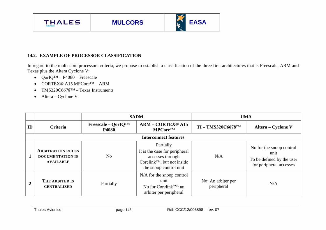
MULCORS
EASA
Thales Avionics page 145 Réf. CCC/12/006898 – rev. 07
14.2. EXAMPLE OF PROCESSOR CLASSIFICATION
In regard to the multi-core processors criteria, we propose to establish a classification of the three first architectures that is Freescale, ARM and
Texas plus the Altera Cyclone V:
QorIQ™ – P4080 – Freescale
CORTEX® A15 MPCore™ – ARM
TMS320C6678™ – Texas Instruments
Altera – Cyclone V
SADM UMA
ID Criteria Freescale – QorIQ™
P4080
ARM – CORTEX® A15
MPCore™ TI – TMS320C6678™ Altera – Cyclone V
Interconnect features
1
ARBITRATION RULES
DOCUMENTATION IS
AVAILABLE
No
Partially
It is the case for peripheral
accesses through
Corelink™, but not inside
the snoop control unit
N/A
No for the snoop control
unit
To be defined by the user
for peripheral accesses
2 THE ARBITER IS
CENTRALIZED Partially
N/A for the snoop control
unit
No for Corelink™: an
arbiter per peripheral
No: An arbiter per
peripheral N/A

MULCORS
EASA
Thales Avionics page 146 Réf. CCC/12/006898 – rev. 07
ID Criteria Freescale – QorIQ™
P4080
ARM – CORTEX® A15
MPCore™ TI – TMS320C6678™ Altera – Cyclone V
3
THE ARBITER CAN
SERVE SEVERAL
TRANSACTIONS
SIMULTANEOUSLY
Yes: up to 4 transactions
per bus cycle Yes Yes Yes
4
THE ARBITRATION
POLICY IS
CONFIGURABLE
N/A
SCU: N/A
Corelink™: Yes, static
priorities are configurable
Yes: static priorities
configurable for bus
masters
SCU: N/A
5
POSSIBLE
CONFIGURATIONS
FOR ARBITRATION
POLICY (SUBSET OF)
N/A
Fixed priorities with Least
Recently Granted policy in
the same priority domain
Fixed priorities
N/A in the same priority
domain
N/A
6
ARBITER INTERNAL
LOGIC INFORMATION
IS AVAILABLE
N/A N/A N/A N/A
7
DEVICE
ALLOCATION RULES
INFORMATION IS
AVAILABLE
N/A N/A N/A
8
DEVICE
ALLOCATION IS
CONFIGURABLE
N/A N/A N/A

MULCORS
EASA
Thales Avionics page 147 Réf. CCC/12/006898 – rev. 07
ID Criteria Freescale – QorIQ™
P4080
ARM – CORTEX® A15
MPCore™ TI – TMS320C6678™ Altera – Cyclone V
9
POSSIBLE
CONFIGURATIONS
FOR DEVICE
ALLOCATION
(DEVICE PER
DEVICE)
(SUBSET OF)
N/A N/A N/A
10
INFORMATION ON
THE NETWORK
TOPOLOGY IS
AVAILABLE
No SCU: N/A
Corelink™: crossbar
Yes, interconnect matrix
available in the public
documentation
SCU: N/A
11
SEVERAL PATHS
EXIST FROM ONE
NODE TO ANOTHER
N/A SCU: N/A
Corelink™: No No N/A
12
INFORMATION ON
THE ROUTING RULES
IS AVAILABLE
N/A
This criteria is irrelevant because there is always one
single path between two nodes in the interconnect
13
POSSIBLE
CONFIGURATIONS
FOR ROUTING RULES
(SUBSET OF)
N/A

MULCORS
EASA
Thales Avionics page 148 Réf. CCC/12/006898 – rev. 07
ID Criteria Freescale – QorIQ™
P4080
ARM – CORTEX® A15
MPCore™ TI – TMS320C6678™ Altera – Cyclone V
14
INFORMATION ON
THE DIFFERENT
KINDS OF
TRANSACTIONS IS
AVAILABLE
No
SCU: No
Corelink™: Yes, they are
described in the AMBA®
ACE protocol
specifications
No SCU: No
15
INFORMATION ON
THE RELATION
BETWEEN ASSEMBLY
INSTRUCTION
EXECUTED AND
TRANSACTIONS SENT
AVAILABLE
No N/A No No
16
THE INTER-
PROCESSORS
INTERRUPTIONS CAN
BE BLOCKED BY THE
INTERCONNECT
No N/A N/A N/A
17
SNOOPING
MECHANISM CAN BE
DISABLED
Yes Yes N/A N/A
18
SNOOPING
MECHANISM CAN BE
CONFINED TO A
SUBSET OF CORES
Yes No N/A N/A

MULCORS
EASA
Thales Avionics page 149 Réf. CCC/12/006898 – rev. 07
ID Criteria Freescale – QorIQ™
P4080
ARM – CORTEX® A15
MPCore™ TI – TMS320C6678™ Altera – Cyclone V
19
THE INTERCONNECT
PROVIDES A CORE
SYNCHRONIZATION
MECHANISM
N/A N/A N/A N/A
Shared resources features
20
ACCESS
RESTRICTION TO THE
INTERRUPT
CONTROLLER FOR
THE SUPERVISOR IS
POSSIBLE
Yes, in the MMU
configuration
Yes, in the MMU
configuration N/A N/A
21
EACH CORE HAS ITS
PRIVATE CLOCK
SOURCE OR PLL
CIRCUIT
No, there are three PLL to
be mapped on eight cores.
The clock source is shared
No, all cores share the
same clock signal N/A N/A
22
THERE IS A SINGLE
CLOCK FOR ALL
CORES
Yes N/A
23
THERE IS A
PROTECTION
MECHANISM THAT
PREVENT A PLL
CONFIGURATION TO
BE CORRUPTED AT
RUNTIME
PLL are configured at
startup, so they are
protected at runtime
N/A N/A N/A

MULCORS
EASA
Thales Avionics page 150 Réf. CCC/12/006898 – rev. 07
ID Criteria Freescale – QorIQ™
P4080
ARM – CORTEX® A15
MPCore™ TI – TMS320C6678™ Altera – Cyclone V
24
THE MAPPING
BETWEEN
AVAILABLE PLL AND
CORES IS
CONFIGURABLE
Yes
25
THE POWER SOURCE
OF EACH CORE CAN
BE PROTECTED FROM
OTHER CORES
CORRUPTION
N/A N/A N/A N/A
26
A CORE CAN BE
HALTED BY OTHER
CORES
N/A N/A N/A N/A
27
A CORE CAN BE SET
IN SLEEP MODE BY
OTHER CORES
N/A N/A N/A N/A
28 EACH CORE HAS A
PRIVATE TIMER Yes
Yes, but located in the
shared space
Yes, but located in the
shared space No
29
TIMERS CAN BE FED
BY THE SAME CLOCK
SOURCE
Yes Yes Yes Timers are provided
within the FPGA fabric.
Their mapping on the
cores is user defined 30
TIMERS CAN BE FED
BY AN EXTERNAL
CLOCK SOURCE
Yes N/A N/A
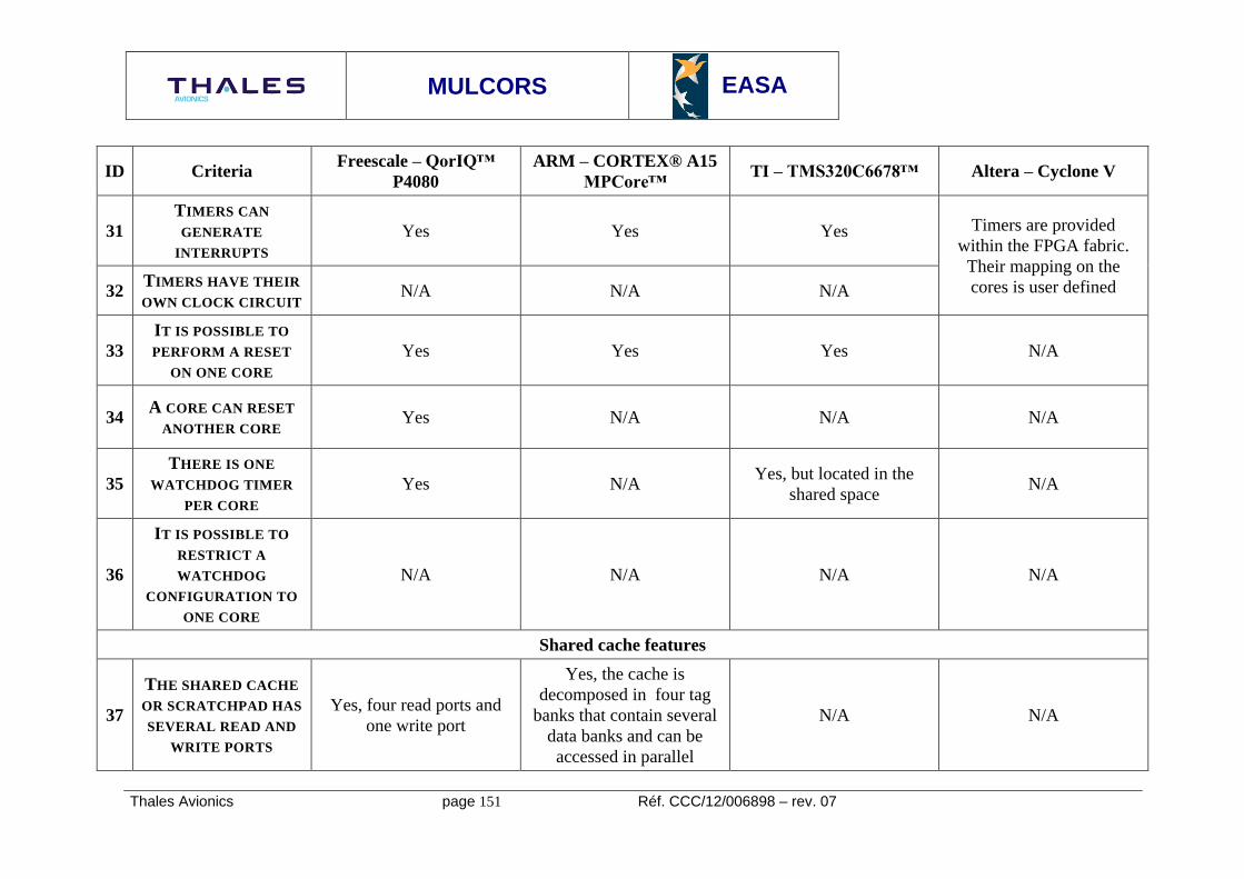
MULCORS
EASA
Thales Avionics page 151 Réf. CCC/12/006898 – rev. 07
ID Criteria Freescale – QorIQ™
P4080
ARM – CORTEX® A15
MPCore™ TI – TMS320C6678™ Altera – Cyclone V
31
TIMERS CAN
GENERATE
INTERRUPTS
Yes Yes Yes Timers are provided
within the FPGA fabric.
Their mapping on the
cores is user defined 32 TIMERS HAVE THEIR
OWN CLOCK CIRCUIT N/A N/A N/A
33
IT IS POSSIBLE TO
PERFORM A RESET
ON ONE CORE
Yes Yes Yes N/A
34 A CORE CAN RESET
ANOTHER CORE Yes N/A N/A N/A
35
THERE IS ONE
WATCHDOG TIMER
PER CORE
Yes N/A Yes, but located in the
shared space N/A
36
IT IS POSSIBLE TO
RESTRICT A
WATCHDOG
CONFIGURATION TO
ONE CORE
N/A N/A N/A N/A
Shared cache features
37
THE SHARED CACHE
OR SCRATCHPAD HAS
SEVERAL READ AND
WRITE PORTS
Yes, four read ports and
one write port
Yes, the cache is
decomposed in four tag
banks that contain several
data banks and can be
accessed in parallel
N/A N/A

MULCORS
EASA
Thales Avionics page 152 Réf. CCC/12/006898 – rev. 07
ID Criteria Freescale – QorIQ™
P4080
ARM – CORTEX® A15
MPCore™ TI – TMS320C6678™ Altera – Cyclone V
38
IT IS POSSIBLE TO
PARTITION A SHARED
CACHE PER WAY
Yes N/A
Irrelevant criteria
N/A
39
IT IS POSSIBLE TO
PARTITION A SHARED
CACHE PER LINES
No No N/A
40
IT IS POSSIBLE TO
CONFIGURE A
SHARED CACHE IN
SRAM
Yes with configurable size
(64K, 256K, 1M) for each
cache
No, but the L2 memory
systems can embed
internal RAM
The Multicore Shared
Memory (MSM) is already
a shared SRAM
N/A
41
IT IS POSSIBLE FOR
ONE CORE TO LOCK
SOME OF ITS
CONTENT IN THE
CACHE
Yes, cache locking is
possible line per line No
Irrelevant criteria
N/A
42
IT IS POSSIBLE FOR
ONE CORE TO LOCK
SOME OF ANOTHER
CORE’S CONTENT IN
THE CACHE
N/A N/A N/A
Core features
43 THE INSTRUCTION
SET IS COMPLETE N/A N/A N/A N/A

MULCORS
EASA
Thales Avionics page 153 Réf. CCC/12/006898 – rev. 07
ID Criteria Freescale – QorIQ™
P4080
ARM – CORTEX® A15
MPCore™ TI – TMS320C6678™ Altera – Cyclone V
44
SEVERAL DIFFERENT
INSTRUCTION SETS
ARE SUPPORTED
No, only Power ISA™ v
2.06 supported
Yes: ARM v7,
THUMB™, JAZELLE™
ISA supported
No, only TMS320C66x™
ISA is supported
Yes: ARM v7, THUMB™
and JAZELLE™ ISA are
supported
45 INSTRUCTIONS HAVE
THE SAME LENGTH Yes No N/A No
46
THE INSTRUCTION
SET CAN BE
EXTENDED (MICRO-
INSTRUCTIONS CAN
BE DEFINED)
N/A
Yes, this is possible
through coprocessor
instructions
N/A
Yes, this is possible
through coprocessor
instructions
47
THE INSTRUCTION
SET IS FULLY
SUPPORTED
No, but the non supported
features are documented.
Aliases are also defined
for some assembly
instructions
N/A Yes N/A
48
THE INSTRUCTION
SET SUPPORTS
HYPERVISOR
PRIVILEGE LEVEL
Yes, hypervisor privilege
obtained with a system call
instruction
Yes, the control
coprocessor can provide
hypervisor privilege
No, only two privilege
levels N/A
49
INSTRUCTIONS CAN
BE RESTRICTED TO
SUPERVISOR OR
HYPERVISOR
PRIVILEGE LEVEL BY
SW CONFIGURATION
N/A N/A N/A N/A

MULCORS
EASA
Thales Avionics page 154 Réf. CCC/12/006898 – rev. 07
ID Criteria Freescale – QorIQ™
P4080
ARM – CORTEX® A15
MPCore™ TI – TMS320C6678™ Altera – Cyclone V
50
THE INSTRUCTION
UNIT CAN FETCH
SEVERAL
INSTRUCTIONS IN
PARALLEL
Yes, up to four N/A Yes, 8 instructions per
fetch N/A
51
THE INSTRUCTION
UNIT HAS A PRE-
FETCH SERVICE
DEPENDING ON A
BRANCH UNIT
Yes Yes N/A N/A
52
THE PRE-FETCH IS
LIMITED INSIDE A
MEMORY PAGE
N/A N/A N/A N/A
53
THE BRANCH
PREDICTION CAN BE
DISABLED
Yes Yes N/A N/A
54
THE BRANCH
PREDICTION POLICY
IS CONFIGURABLE
STATIC/DYNAMIC
Yes N/A N/A N/A
55
THE LSU REORDERS
THE MEMORY AND
IO TRANSACTIONS
Yes N/A N/A N/A

MULCORS
EASA
Thales Avionics page 155 Réf. CCC/12/006898 – rev. 07
ID Criteria Freescale – QorIQ™
P4080
ARM – CORTEX® A15
MPCore™ TI – TMS320C6678™ Altera – Cyclone V
56
TRANSACTION
REORDERING CAN BE
DISABLED
N/A N/A N/A N/A
57
INTERNAL
REGISTERS ARE
RENAMED BEFORE
INSTRUCTION
EXECUTION
Yes Yes N/A Yes
58
THE MMU IS
CENTRALIZED OR
DISTRIBUTED AMONG
THE CORES
One MMU per core, but
additional filter on
addresses through the
Local Access Windows at
platform level
One MMU per core
managed by the CP15
coprocessor
One Memory Protection
Unit (no memory
virtualization service) per
core
One MMU per core
59 TLB STORAGE
CHARACTERISTICS
L1 data/instruction TLB
L2 unified TLB
Fixed 4K pages, and
variable 4K to 4G pages
L1 data/instructions TLB
L2 unified TLB
Translation Table stored in
the cache or the main
memory
Fixed 4K pages in L1 TLB
Variable 4K to 16M pages,
support for Large Pages
2M and 1G
Programmable pages sizes N/A

MULCORS
EASA
Thales Avionics page 156 Réf. CCC/12/006898 – rev. 07
ID Criteria Freescale – QorIQ™
P4080
ARM – CORTEX® A15
MPCore™ TI – TMS320C6678™ Altera – Cyclone V
60
THE TLB
REPLACEMENT
ALGORITHM IS
IMPLEMENTED IN
HARDWARE OR
SOFTWARE
Hardware for L1
data/instruction TLB,
software for unified L2
TLB
Coherency L1/L2 ensured
by hardware
Hardware replacement
mechanism: when a L2
TLB miss occurs, the
MMU performs a
Translation Table Walk
Software management of
the memory protection
unit
N/A
61 THE PAGE SIZE IS
FIXED OR VARIABLE Both Fixed in L1, variable in L2 Variable N/A
62 THE MMU DETECTS
PAGES OVERLAPPING Yes N/A N/A N/A
63
PRIVATE CACHE AND
SCRATCHPADS
CONTENTS
32k data, 32 K instruction
L1
256k unified L2
32k data, 32k instruction
32K data, 32K instruction
Both can be configured
partially or fully as SRAM
A store instruction cannot
be written in L1 data cache
32k data, 32k instruction
64
PRIVATE CACHE
REPLACEMENT
POLICY
Least Recently Used Least Recently Used
The cache is one way, so
the replacement policy is
trivial
Least recently Used
Hardware accelerators for network processing features
65
THE OVERALL
ARCHITECTURE IS
DOCUMENTED
Partially for Data Path
Acceleration Architecture
(network stream
processing)
Irrelevant criteria: The
CORTEX® A15
MPCore™ IP is not
provided with I/O devices
for network processing
Network coprocessor and
multicore navigator.
Public documentation
available
To be defined at design
time by the user

MULCORS
EASA
Thales Avionics page 157 Réf. CCC/12/006898 – rev. 07
ID Criteria Freescale – QorIQ™
P4080
ARM – CORTEX® A15
MPCore™ TI – TMS320C6678™ Altera – Cyclone V
66
THE HARDWARE
ACCELERATOR
EMBEDS MICROCODE
Yes, in the Frame
Manager. This microcode
is proprietary
Assumed yes, as there is a
Rx core and a Tx core
67
THE HARDWARE
ACCELERATOR
CONTAINS INTERNAL
MEMORY
Yes Yes
68
THE ACCELERATOR
INTERNAL MEMORY
IS PROTECTED
AGAINST SEU/MBU
All internal memory is
protected with ECC N/A
69
THE HARDWARE
ACCELERATOR CAN
BE BYPASSED
Yes: for network usage, a
network controller can be
mapped on the PCI or
PCIe bus rather than
DPAA
Yes: for a network usage,
a network controller can
be mapped on the PCIe

MULCORS
EASA
Thales Avionics page 158 Réf. CCC/12/006898 – rev. 07
ID Criteria Freescale – QorIQ™
P4080
ARM – CORTEX® A15
MPCore™ TI – TMS320C6678™ Altera – Cyclone V
Support for debug
70
IT IS POSSIBLE TO
DEBUG ON A SINGLE
CORE WITHOUT
AFFECTING THE
OTHERS
Yes, internal performance
monitors on each core,
JTAG interrupt available
core per core, GDB stub
provided with TOPAZ©
(Freescale hypervisor),
HyperTRK library for
JTAG debug on top of
TOPAZ©
Performance monitors,
ARM v7 debug unit,
CoreSight™ interface
Yes using the Debug and
trace proprietary solution N/A
71
IT IS POSSIBLE TO
DEBUG ON ALL
CORES
SYNCHRONOUSLY
N/A N/A N/A N/A
72
IT IS POSSIBLE TO
HAVE A TRACE OF
THE TRANSACTIONS
GENERATED BY EACH
CORES
Partially: Aurora interface
gives a limited view of the
Corenet™ activity
Yes: Program Trace
Macrocell, which is a real-
time transaction tracer
included in CoreSight™.
Yes using the Debug and
trace proprietary solution N/A
Manufacturer related criteria
73
THE
MANUFACTURER HAS
EXPERIENCE IN THE
AVIONIC DOMAIN
Yes N/A Yes No

MULCORS
EASA
Thales Avionics page 159 Réf. CCC/12/006898 – rev. 07
ID Criteria Freescale – QorIQ™
P4080
ARM – CORTEX® A15
MPCore™ TI – TMS320C6678™ Altera – Cyclone V
74
THE
MANUFACTURER IS
INVOLVED IN THE
CERTIFICATION
PROCESS FOR THE
STUDIED PLATFORM
Yes N/A N/A N/A
75
THE
MANUFACTURER
PUBLISHES SPECIFIC
COMMUNICATIONS
Yes No No No
76
THE
MANUFACTURER HAS
A SUFFICIENT LIFE
EXPECTANCY
Yes Yes Yes Yes
77
THE
MANUFACTURER
ENSURES A LONG
TERM SUPPORT
N/A N//A N/A N/A
78
THE
MANUFACTURER
PROVIDES
INFORMATION ON
THE PROCESSOR
DESIGN
Partially under NDA Partially, with the
functional description Yes Partially

MULCORS
EASA
Thales Avionics page 160 Réf. CCC/12/006898 – rev. 07
ID Criteria Freescale – QorIQ™
P4080
ARM – CORTEX® A15
MPCore™ TI – TMS320C6678™ Altera – Cyclone V
79
THE
MANUFACTURER
PROVIDES
INFORMATION ON
BUGS AND ERRATA
Yes N/A N/A N/A
80
THE
MANUFACTURER
PROVIDES
INFORMATION ON
SER (SEU/MBU)
Partially under NDA N/A N/A N/A

Postal address Visiting address Tel Fax Mail Web