Embed Size (px)
Citation preview
IEEE PHOTONICS TECHNOLOGY LETTERS, VOL. 33, NO. 8, APRIL 15, 2021 391
Multi-Band LFM Signal With UnidenticalBandwidths Subjected to Optical
Injection in a DFB LaserHao Chen, Bikash Nakarmi , Senior Member, IEEE, and Shilong Pan , Senior Member, IEEE
Abstract— This letter demonstrates a tunable multi-band linearfrequency modulation (LFM) signal with improved and uniden-tical bandwidths subjected to optical injection in a distributed-feedback (DFB) laser. In the proposed scheme, an optical beamis divided into two paths, one modulating with a basebandLFM signal and another with a power-varying signal. The basicprinciple of the proposed scheme is the optical beating of thecarrier-suppressed ±1st sidebands in one path and the red-shiftedemission mode of the DFB laser after optical injection in anotherpath. In the experiment, the generated three LFM signals havethe bandwidths of 11.5 GHz (from 23.0 to 34.5 GHz), 7.5 GHz(from 15.0 to 22.5 GHz), and 4 GHz (from 8.0 to 12.0 GHz) inone period of 1µ s. Moreover, we analyze the effect of the injectedbeam’s frequency and power on the bandwidth tunability of thegenerated LFM signals.
Index Terms— Multi-band LFM signal, optical injection, DFBlaser.
I. INTRODUCTION
L INEAR frequency modulation (LFM) signal is a typicaland widely used pulse compression waveform in radar
systems due to its ability to achieve an extensive detectionrange and a high range resolution [1]. Conventionally, LFMsignals generated by the electrical methods have a limited fre-quency range, which restricts the radar system’s performance.To overcome the drawbacks of the electrically generatedLFM signals, several photonics-based approaches have beenproposed to generate a single LFM signal with the improvedfrequency range and bandwidth [2]–[5]. Even though the rangeresolution is improved to the ultra-high range, a single-bandradar system fails to fulfill the applications such as velocitydetection and the Multiple Input Multiple Output (MIMO)radar system. Hence, a multi-band LFM signal with largerbandwidth, higher center frequency, and flexible tunabilityis of utmost importance for multi-functional modern radarsystems [6].
Manuscript received December 28, 2020; revised February 2, 2021; acceptedMarch 4, 2021. Date of publication March 10, 2021; date of current versionMarch 17, 2021. This work was supported in part by National Key Researchand Development Program of China under Grant 2018YFB2201803; in part bythe National Natural Science Foundation of China under Grant 61650110515;and in part by the Fundamental Research Funds for the Central Universities.(Corresponding authors: Bikash Nakarmi; Shilong Pan.)
The authors are with the Key Laboratory of Radar Imaging and MicrowavePhotonics, Ministry of Education, Nanjing University of Aeronauticsand Astronautics, Nanjing 210016, China (e-mail: [email protected];[email protected]; [email protected]).
Color versions of one or more figures in this letter are available athttps://doi.org/10.1109/LPT.2021.3065387.
Digital Object Identifier 10.1109/LPT.2021.3065387
Several photonics approaches have been proposed for multi-band LFM signal generation. Among them, one approachis to use a single or dual-band LFM baseband signal tomodulate an optical carrier by high-speed Mach-Zehnder mod-ulator (MZM) for optical frequency multiplication, optical fre-quency comb and others [7]–[12] and then generate multi-bandLFM signal. But this method suffers from a limited modulationindex and needs a high-speed modulator. Fourier domainmode-locked optoelectronic oscillator has been proposed togenerate a dual-band LFM signal, which suffers from limitedbandwidth and poor linearity [13], [14]. Another approach isbased on dual-beam injection to distributed-feedback (DFB)laser with Period-one (P1) oscillation state, where one ofthe injected beams is power-controlled by a near-saw toothcontrol signal [15]. But LFM signals generated from theseapproaches have either the same or opposite chirps, lackingflexibility and tunability. However, with the development ofmulti-function radar for different purposes, the generation ofmulti-band LFM signal with different bandwidths is requiredfor detecting various targets, moving targets and other scenar-ios. Hence, multi-band LFM signal generation with unidenticaland tunable bandwidths is an urgent task that needs to besolved.
This letter proposes a simple structure for multi-band LFMsignal generation with unidentical and tunable bandwidthsand high-frequency range. In the proposed scheme, an opticalbeam is divided into two paths. The optical beam in onepath is modulated by a low-frequency electrical LFM signalfor generating the carrier-suppressed ±1st sidebands. A saw-tooth waveform from an arbitrary wave generator (AWG)modulates the optical beam in another path, which functionsas an intensity-controller of the injected beam. The injection ofthe intensity-controlled beam red-shifts the emission frequencyof the DFB laser, a slave laser. Hence, the optical beatingof the optical beams from two paths generates three LFMsignals with unidentical bandwidths. The bandwidths of thegenerated LFM signals are given by the absolute value of sumand difference of the bandwidth of the modulating LFM signaland the red-shifted frequency range and double the bandwidthof the modulating LFM signal. In the experiment, three LFMsignals with unidentical bandwidths of 11.5 GHz (from 23.0to 34.5 GHz), 7.5 GHz (from 15.0 to 22.5 GHz), and 4 GHz(from 8.0 to 12.0 GHz) are generated. Also, the tunabilityanalysis in bandwidth and center frequency of the generatedLFM signals is demonstrated.
1041-1135 © 2021 IEEE. Personal use is permitted, but republication/redistribution requires IEEE permission.See https://www.ieee.org/publications/rights/index.html for more information.
Authorized licensed use limited to: NANJING UNIVERSITY OF AERONAUTICS AND ASTRONAUTICS. Downloaded on June 24,2021 at 06:47:12 UTC from IEEE Xplore. Restrictions apply.
392 IEEE PHOTONICS TECHNOLOGY LETTERS, VOL. 33, NO. 8, APRIL 15, 2021
II. EXPERIMENT SET UP AND OPERATING PRINCIPLE
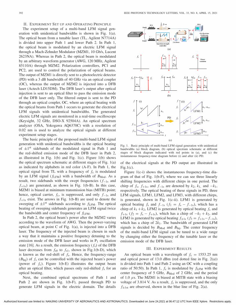
The experiment setup of a multi-band LFM signal gen-eration with unidentical bandwidths is shown in Fig. 1(a).The optical beam from a tunable laser (TL, Agilent N7714A)is divided into upper Path 1 and lower Path 2. In Path 1,the optical beam is modulated by an electric LFM signalthrough a Mach-Zehnder Modulator (MZM1, 10 Gb/s, Lucent2623NA). Whereas in Path 2, the optical beam is modulatedby an arbitrary waveform generator (AWG, 120 MHz, Agilent85110A) through MZM2. Polarization controllers, PC1 andPC2, are used to control the polarization of optical beams.The output of MZM1 is directly sent to a photoelectric detector(PD) with a 3 dB bandwidth of 40 GHz via an optical coupler(OC), whereas the output of MZM2 is injected into a DFBlaser (Actech LD15DM). The DFB laser’s output after opticalinjection is sent to an optical filter to pass the emission modeof the DFB laser only. The filtered output is sent to the PDthrough an optical coupler, OC, where an optical beating withthe optical beams from Path 1 occurs to generate the electricalLFM signals with unidentical bandwidths. The generatedelectric LFM signals are monitored in a real-time oscilloscope(Keysight, 32 GHz, DSO-X 92504A). An optical spectrumanalyzer (OSA, Yokogawa AQ6370C) with a resolution of0.02 nm is used to analyze the optical signals at differentexperiment setup stages.
The basic principle of the proposed multi-band LFM signalgeneration with unidentical bandwidths is the optical beatingof ±1st sidebands of the modulated signal in Path 1 andthe red-shifted emission mode of the DFB laser in Path 2,as illustrated in Fig. 1(b) and Fig. 1(c). Figure 1(b) showsthe optical spectrum schematic at different stages of Fig. 1(a)as indicated by alphabets in red color (A-F). In Path 1, theoptical signal from TL with a frequency of fc is modulatedby an LFM signal ( fLFM) with a bandwidth of BMod. As aresult, two sidebands with the swept frequencies ( f−1s andf+1s) are generated, as shown in Fig. 1(b-B). In this case,MZM1 is biased at minimum transmission bias (MITB) point;hence, optical carrier, fc, is suppressed, and only f−1s andf+1s exist. The arrows in Fig. 1(b-B) are used to denote thesweeping of ±1st sidebands according to fLFM. The opticalbeating of sweeping sidebands generates an LFM signal twicethe bandwidth and center frequency of fLFM.
In Path 2, the optical beam’s power after the MZM2 variesaccording to the waveform of AWG. Then the power-varyingoptical beam, at point C of Fig. 1(a), is injected into a DFBlaser. The frequency of the injected beam is chosen in sucha way that it maintains a positive frequency detuning to theemission mode of the DFB laser and works in P1 oscillationstate [16]. As a result, the emission frequency ( fs) of the DFBlaser decreases from fs0 to fs1, shown in Fig.1(b-D), whichis known as the red-shift of fs. Hence, the frequency-range(BInj) of fs can be controlled with the injected beam’s power(power of fc). Figure 1(b-E) illustrates the output beamafter an optical filter, which passes only red-shifted fs for anoptical beating.
Next, the combined optical spectrums of Path 1 andPath 2 are shown in Fig. 1(b-F), passed through PD togenerate LFM signals in the electric domain. The details
Fig. 1. Basic principle of multi-band LFM signal generation with unidenticalbandwidths (a) block diagram, (b) optical spectrum schematic at differentstages of block diagram indicated with red points in (a), and (c) theinstantaneous frequency-time diagram before (i) and after (ii) PD.
of the electrical signals at the PD output are illustrated inFig.1(c).
Figure 1(c-i) shows the instantaneous frequency-time dia-gram of that of Fig. 1(b-F), where we can see three linearlyshifting frequencies with different chirps in one period. Thechirp of fs, f+1s, and f−1s are denoted by k2, k1, and −k1,respectively. The optical beating of these signals in PD, threeLFM signals, LFM1, LFM2, and LFM3, with different chirps,is generated, shown in Fig. 1(c-ii). LFM1 is generated byoptical beating fs and f−1s ( f1 = fs − f−1s), which has achirp of k1 + k2, LFM2 is generated by optical beating fs andf+1s ( f2 = fs − f+1s), which has a chirp of −k1 + k2, andLFM3 is generated by optical beating f±1s ( f3 = f+1s− f−1s),which has a chirp of 2k1. The bandwidth of generated LFMsignals is decided by BMod and BInj. The center frequencyof the multi-band LFM signal can be tuned to a wide rangeby changing either the frequency of the tunable laser or theemission mode of the DFB laser.
III. EXPERIMENT RESULTS
An optical beam with a wavelength of fc = 1553.25 nmand optical power of 13.0 dBm (red dotted line in Fig. 2(a))is divided into Path 1 and Path 2 using an OC with a couplingratio of 50:50). In Path 1, fc is modulated by fLFM with thecenter frequency of 5 GHz, BMod of 2 GHz, and the periodof 1.0 µs. The MZM1 is biased at MITB state with a biasingvoltage of 3.814 V. As a result, fc is suppressed, and the onlyf±1st are observed, shown in the blue line of Fig. 2(a).
Authorized licensed use limited to: NANJING UNIVERSITY OF AERONAUTICS AND ASTRONAUTICS. Downloaded on June 24,2021 at 06:47:12 UTC from IEEE Xplore. Restrictions apply.
CHEN et al.: MULTI-BAND LFM SIGNAL WITH UNIDENTICAL BANDWIDTHS SUBJECTED TO OPTICAL INJECTION 393
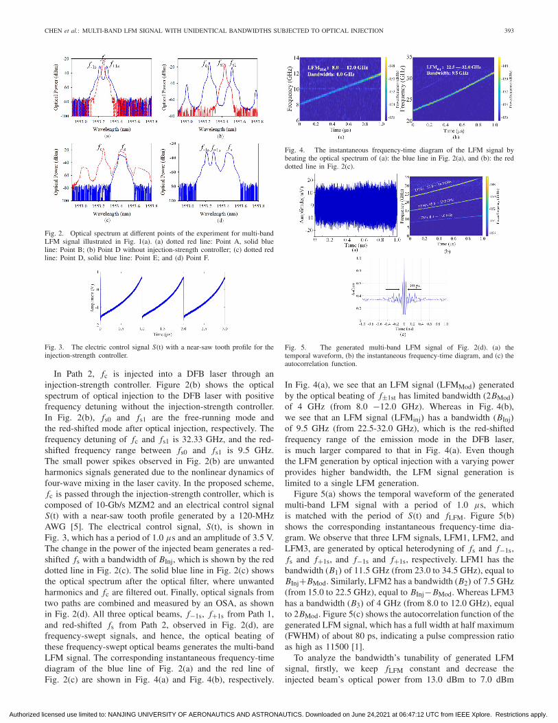
Fig. 2. Optical spectrum at different points of the experiment for multi-bandLFM signal illustrated in Fig. 1(a). (a) dotted red line: Point A, solid blueline: Point B; (b) Point D without injection-strength controller; (c) dotted redline: Point D, solid blue line: Point E; and (d) Point F.
Fig. 3. The electric control signal S(t) with a near-saw tooth profile for theinjection-strength controller.
In Path 2, fc is injected into a DFB laser through aninjection-strength controller. Figure 2(b) shows the opticalspectrum of optical injection to the DFB laser with positivefrequency detuning without the injection-strength controller.In Fig. 2(b), fs0 and fs1 are the free-running mode andthe red-shifted mode after optical injection, respectively. Thefrequency detuning of fc and fs1 is 32.33 GHz, and the red-shifted frequency range between fs0 and fs1 is 9.5 GHz.The small power spikes observed in Fig. 2(b) are unwantedharmonics signals generated due to the nonlinear dynamics offour-wave mixing in the laser cavity. In the proposed scheme,fc is passed through the injection-strength controller, which iscomposed of 10-Gb/s MZM2 and an electrical control signalS(t) with a near-saw tooth profile generated by a 120-MHzAWG [5]. The electrical control signal, S(t), is shown inFig. 3, which has a period of 1.0 µs and an amplitude of 3.5 V.The change in the power of the injected beam generates a red-shifted fs with a bandwidth of BInj, which is shown by the reddotted line in Fig. 2(c). The solid blue line in Fig. 2(c) showsthe optical spectrum after the optical filter, where unwantedharmonics and fc are filtered out. Finally, optical signals fromtwo paths are combined and measured by an OSA, as shownin Fig. 2(d). All three optical beams, f−1s, f+1s from Path 1,and red-shifted fs from Path 2, observed in Fig. 2(d), arefrequency-swept signals, and hence, the optical beating ofthese frequency-swept optical beams generates the multi-bandLFM signal. The corresponding instantaneous frequency-timediagram of the blue line of Fig. 2(a) and the red line ofFig. 2(c) are shown in Fig. 4(a) and Fig. 4(b), respectively.
Fig. 4. The instantaneous frequency-time diagram of the LFM signal bybeating the optical spectrum of (a): the blue line in Fig. 2(a), and (b): the reddotted line in Fig. 2(c).
Fig. 5. The generated multi-band LFM signal of Fig. 2(d). (a) thetemporal waveform, (b) the instantaneous frequency-time diagram, and (c) theautocorrelation function.
In Fig. 4(a), we see that an LFM signal (LFMMod) generatedby the optical beating of f±1st has limited bandwidth (2BMod)of 4 GHz (from 8.0 −12.0 GHz). Whereas in Fig. 4(b),we see that an LFM signal (LFMinj) has a bandwidth (BInj)of 9.5 GHz (from 22.5-32.0 GHz), which is the red-shiftedfrequency range of the emission mode in the DFB laser,is much larger compared to that in Fig. 4(a). Even thoughthe LFM generation by optical injection with a varying powerprovides higher bandwidth, the LFM signal generation islimited to a single LFM generation.
Figure 5(a) shows the temporal waveform of the generatedmulti-band LFM signal with a period of 1.0 µs, whichis matched with the period of S(t) and fLFM. Figure 5(b)shows the corresponding instantaneous frequency-time dia-gram. We observe that three LFM signals, LFM1, LFM2, andLFM3, are generated by optical heterodyning of fs and f−1s,fs and f+1s, and f−1s and f+1s, respectively. LFM1 has thebandwidth (B1) of 11.5 GHz (from 23.0 to 34.5 GHz), equal toBInj+BMod. Similarly, LFM2 has a bandwidth (B2) of 7.5 GHz(from 15.0 to 22.5 GHz), equal to BInj−BMod. Whereas LFM3has a bandwidth (B3) of 4 GHz (from 8.0 to 12.0 GHz), equalto 2BMod. Figure 5(c) shows the autocorrelation function of thegenerated LFM signal, which has a full width at half maximum(FWHM) of about 80 ps, indicating a pulse compression ratioas high as 11500 [1].
To analyze the bandwidth’s tunability of generated LFMsignal, firstly, we keep fLFM constant and decrease theinjected beam’s optical power from 13.0 dBm to 7.0 dBm
Authorized licensed use limited to: NANJING UNIVERSITY OF AERONAUTICS AND ASTRONAUTICS. Downloaded on June 24,2021 at 06:47:12 UTC from IEEE Xplore. Restrictions apply.
394 IEEE PHOTONICS TECHNOLOGY LETTERS, VOL. 33, NO. 8, APRIL 15, 2021
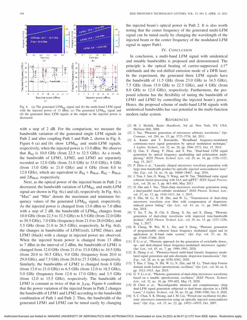
Fig. 6. (a) The generated LFMInj signal and (b) the multi-band LFM signalwith the injected power of 13 dBm; (c) The generated LFMInj signal and(d) the generated three LFM signals at the output as the injected power isdecreased.
with a step of 2 dB. For the comparison, we measure thebandwidth variation of the generated single LFM signals inPath 2 and after coupling Path 1 and Path 2, shown in Fig. 6.Figure 6 (a) and (b) show LFMInj and multi-LFM signals,respectively, when the injected power is 13.0 dBm. We observethat BInj is 10.0 GHz (from 22.5 to 32.5 GHz). As a result,the bandwidth of LFM1, LFM2, and LFM3 are separatelyrecorded as 12.0 GHz (from 21.0 GHz to 33.0 GHz), 8 GHz(from 13.0 GHz to 21.0 GHz) and 4 GHz (from 8.0 to12.0 GHz), which are equivalent to BInj + BMod, BInj − BMod,and 2BMod, respectively.
Next, as the optical power of the injected beam in Path 2 isdecreased, the bandwidth variation of LFMInj, and multi-LFMsignal are shown in Fig. 6(c) and (d), respectively. In Fig. 6(c),“Max” and “Min” denote the maximum and minimum fre-quency values of the generated LFMInj signal, respectively.As the injected power is changed from 13.0 dBm to 7.0 dBmwith a step of 2 dB, the bandwidth of LFMInj changes from10.0 GHz (from 22.5 to 32.5 GHz) to 8.5 GHz (from 22.0 GHzto 30.5 GHz), 7.0 GHz (frequency from 21.0 to 28.0 GHz), and5.5 GHz (from 21.0 to 26.5 GHz), respectively. In Fig. 6(d),the changes in bandwidths of LFM1(red), LFM2 (blue), andLFM3 (black) with a change in injected power are observed.When the injected beam power is changed from 13 dBmto 7 dBm in the interval of 2 dBm, the bandwidth of LFM1 ischanged from 12.0 GHz (from 21.0 to 33.0 GHz) to 10.5 GHz(from 20.0 to 30.5 GHz), 9.0 GHz (frequency from 20.0 to29.0 GHz), and 7.5 GHz (from 20.0 to 27.5 GHz), respectively.Similarly, the bandwidths of LFM2 is changed from 8 GHz(from 13.0 to 21.0 GHz) to 6.5 GHz (from 12.0 to 18.5 GHz),5.0 GHz (frequency from 12.0 to 17.0 GHz), and 3.5 GHz(from 12.0 to 15.5 GHz), respectively. The bandwidth ofLFM3 is constant as twice of that in fLFM. Figure 6 confirmsthat the power variation of the injected beam in Path 2 changesthe bandwidth of LFM1 and LFM2 according to the bandwidthcombination of Path 1 and Path 2. Thus, the bandwidth of thegenerated LFM1 and LFM2 can be tuned easily by changing
the injected beam’s optical power in Path 2. It is also worthnoting that the center frequency of the generated multi-LFMsignal can be tuned easily by changing the wavelength of theinjected beam or the center frequency of the modulated LFMsignal in upper Path1.
IV. CONCLUSION
In conclusion, a multi-band LFM signal with unidenticaland tunable bandwidths is proposed and demonstrated. Theprinciple is the optical beating of carrier-suppressed ±1st
sidebands and the red-shifted emission mode of a DFB laser.In the experiment, the generated three LFM signals havethe bandwidth of 11.5 GHz (from 23.0 GHz to 34.5 GHz),7.5 GHz (from 15.0 GHz to 22.5 GHz), and 4 GHz (from8.0 GHz to 12.0 GHz), respectively. Furthermore, the pro-posed scheme has the flexibility of tuning the bandwidth ofLFM1 and LFM2 by controlling the injected beam’s power.Hence, the proposed scheme of multi-band LFM signals withunidentical bandwidths has vast potential in the multi-functionmodern radar system.
REFERENCES
[1] M. I. Skolnik, Radar Handbook, 3rd ed. New York, NY, USA:McGraw-Hill, 2008.
[2] J. Yao, “Photonic generation of microwave arbitrary waveforms,” Opt.Commun., vol. 284, no. 15, pp. 3723–3736, Jul. 2011.
[3] A. Kanno and T. Kawanishi, “Broadband frequency-modulatedcontinuous-wave signal generation by optical modulation technique,”J. Lightw. Technol., vol. 32, no. 20, pp. 3566–3572, Oct. 15, 2014.
[4] Q. Guo, F. Zhang, P. Zhou, and S. Pan, “Dual-band LFM signalgeneration by optical frequency quadrupling and polarization multi-plexing,” IEEE Photon. Technol. Lett., vol. 29, no. 16, pp. 1320–1323,Aug. 15, 2017.
[5] P. Zhou et al., “Linearly chirped microwave waveform generation withlarge time-bandwidth product by optically injected semiconductor laser,”Opt. Exp., vol. 24, no. 16, pp. 18460–18467, Aug. 2016.
[6] J. Tian, J. Sun, G. Wang, Y. Wang, and W. Tan, “Multiband radar signalcoherent fusion processing with IAA and apFFT,” IEEE Signal Process.Lett., vol. 20, no. 5, pp. 463–466, May 2013.
[7] D. Zhu and J. Yao, “Dual-chirp microwave waveform generation usinga dual-parallel mach-zehnder modulator,” IEEE Photon. Technol. Lett.,vol. 27, no. 13, pp. 1410–1413, Jul. 1, 2015.
[8] S. Zhu, M. Li, N. H. Zhu, and W. Li, “Transmission of dual-chirpmicrowave waveform over fiber with compensation of dispersion-induced power fading,” Opt. Lett., vol. 43, no. 11, pp. 2466–2469,Jun. 2018.
[9] Y. Xu, T. Jin, H. Chi, S. Zheng, X. Jin, and X. Zhang, “Photonicgeneration of dual-chirp waveforms with improved time-bandwidthproduct,” IEEE Photon. Technol. Lett., vol. 29, no. 15, pp. 1253–1256,Aug. 1, 2017.
[10] R. Cheng, W. Wei, W. L. Xie, and Y. Dong, “Photonic generationof programmable coherent linear frequency modulated signal and itsapplication in X-band radar system,” Opt. Exp. vol. 27, no. 26,pp. 37469–37480, 2019.
[11] P. Li et al., “Photonic approach for the generation of switchable down-,up-, and dual-chirped linear frequency-modulated microwave signals,”Opt. Lett., vol. 45, no. 7, pp. 1990–1993, 2020.
[12] K. Zhang et al., “Photonics-based multi-band linearly frequency modu-lated signal generation and anti-chromatic dispersion transmission,” Opt.Exp., vol. 28, no. 6, pp. 8350–8362, 2020.
[13] T. Hao, J. Tang, N. Shi, W. Li, N. Zhu, and M. Li, “Dual-chirp Fourierdomain mode-locked optoelectronic oscillator,” Opt. Lett., vol. 44, no. 8,pp. 1912–1915, Apr. 2019.
[14] G. Y. Li et al., “Photonic generation of dual-chirp microwave waveformsbased on a tunable optoelectronic oscillator,” IEEE Photon. Technol.Lett., vol. 32, no. 10, pp. 559–602, May 15, 2020.
[15] H. Chen et al., “Reconfigurable identical and complementary chirpdual-LFM signal generation subjected to dual-beam injection in a DFBLaser,” J. Lightw. Technol., vol. 38, no. 19, pp. 5500–5580, Oct. 8, 2020.
[16] S. C. Chan, S. K. Hwang, and J. M. Liu, “Period-one oscillation for pho-tonic microwave transmission using an optically injected semiconductorlaser,” Opt. Exp., vol. 15, no. 22, pp. 14921–14935, Oct. 2007.
Authorized licensed use limited to: NANJING UNIVERSITY OF AERONAUTICS AND ASTRONAUTICS. Downloaded on June 24,2021 at 06:47:12 UTC from IEEE Xplore. Restrictions apply.