Embed Size (px)
Citation preview
MULTI-LINE INDUCTION RANGES
Multi-Line
TYPE: 3500, 5500
Installation and Operation Manual
S/N: Rev.: 2.0

17.6.2003 Rev. 2.0
Dear Customer,
Congratulations on deciding to choose a Metos appliance for your kitchen activities. Youmade an excellent choice. We will do our best to make you a satisfied Metos customerlike thousands of customers we have around the world.
Please read this manual carefully. You will learn correct, safe and efficient working meth-ods in order to get the best possible benefit from the appliance. The instructions and hintsin this manual will give you a quick and easy start, and you will soon note how nice it isto use the Metos equipment.
All rights are reserved for technical changes.
You will find the main technical data on the rating plate fixed to the equipment. When youneed service or technical help, please let us know the serial number shown on the ratingplate. This will make it easier to provide you with correct service.
For your convenience, space is provided below for you to record your local Metos servicecontact information.
METOS TEAM
Metos service phone number:...............................................................................................
Contact person:....................................................................................................................

17.6.2003 Rev. 2.0
17.6.2003 Rev.
1. General .......................................................................................................... 11.1 Symbols used in the manual .......................................................................................... 11.2 Symbols used on the appliance ...................................................................................... 11.3 Checking the relationship of the appliance and the manual .......................................... 1
2. Safety .............................................................................................................. 32.1 Safe use of the appliance ............................................................................................... 3
2.1.1 Changing the settings and adjustments .................................................................. 42.2 Safety instructions in case of a malfunction .................................................................. 42.3 Disposal of the appliance ............................................................................................... 42.4 Other prohibitions .......................................................................................................... 4
3. Functional description .................................................................................. 53.1 Construction .................................................................................................................. 5
4. Operation instructions ................................................................................. 74.1 Before using the appliance ............................................................................................ 7
4.1.1 Operating test ......................................................................................................... 74.2 Operation procedures ..................................................................................................... 7
4.2.1 Cooking with “Power stages” ................................................................................ 84.2.2 Cooking with “Hold function” ............................................................................... 84.2.3 Cooking with “Temperature regulation” ............................................................... 94.2.4 Choise of pan preselection place ........................................................................... 94.2.5 Calibration of pans ................................................................................................. 94.2.6 Calibration process 20°C ....................................................................................... 94.2.7 Calibration process 100°C ................................................................................... 104.2.8 Unfinished calibration process ............................................................................. 104.2.9 Saving of temperature constant ............................................................................ 104.2.10 Indication of the actual temperature .................................................................. 104.2.11 Indication of set-point temperature .................................................................... 10
4.3 After use ...................................................................................................................... 114.3.1 Cleaning .............................................................................................................. 114.3.2 Periodic service .................................................................................................... 114.3.3 Out of operation .................................................................................................. 11
5. Short instruction ......................................................................................... 12
6. Installation ................................................................................................... 156.1 Preparing the installation ............................................................................................. 156.2 Installation ................................................................................................................... 15
17.6.2003 Rev.
6.3 Positioning the appliance ............................................................................................. 166.4 Electrical connections .................................................................................................. 16
6.4.1 Single phase supply ............................................................................................. 176.4.2 Three phase supply .............................................................................................. 17
6.5 Measures after the installation ..................................................................................... 18
8. Technical specifications .............................................................................. 27
17.6.2003 Rev. 2.0General
1. General
Carefully read the instructions in this manual as they contain important information re-garding proper, efficient and safe installation, use and maintenance of the appliance.
Keep this manual in a safe place for eventual use by other operators of the appliance.
The installation of this appliance must be carried out in accordance with the manufactur-er’s instructions and following local regulations. The connection of the appliance to theelectric and water supply must be carried out by qualified persons only.
Persons using this appliance should be specifically trained in its operation.
Switch off the appliance in the case of failure or malfunction. The periodical functionchecks requested in the manual must be carried out according to the instructions. Have theappliance serviced by a technically qualified person authorized by the manufacturer andusing original spare parts.
Not complying with the above may put the safety of the appliance in danger.
1.1 Symbols used in the manual
This symbol informs about a situation where a safety risk might be at hand. Given instruc-tions are mandatory in order to prevent injury.
This symbol informs about the right way to perform in order to prevent bad results, appli-ance damage or hazardous situations.
This symbol informs about recommendations and hints that help to get the best perform-ance out of the appliance.
This symbol informs about a function that has to be taken into account in self-control.
1.2 Symbols used on the appliance
This symbol on a part informs about electrical terminals behind the part. The removal ofthe part must be carried out by qualified persons only.
1.3 Checking the relationship of the appliance and the manual
The rating plate of the appliance indicates the serial number of the appliance. If the man-uals are missing, it is possible to order new ones from the manufacturer or the local rep-
1
17.6.2003 Rev. 2.0General
resentative. When ordering new manuals it is essential to quote the serial number shownon the rating plate.
2
17.6.2003 Rev. 2.0Safety
2. Safety
2.1 Safe use of the appliance
The Multi-Line induction cookers are specially suitable as cookers in the kitchen or forthe preparation of meals on the table. A cooker can be used for cooking, warming up,keeping warm, flambéing, roasting, etc. food. The cooking or finishing process with Mul-ti-Line induction appliances must be carried out with recommended types and sizes ofpans. Do not use any NO NAME pans.
Information signs mounted directly on the cooker must be observed at all times and keptin a fully legible condition.
Danger for persons, for the environment and for the cooker can result of non-observanceof the safety information. Certain risks may be associated with non-observance of precau-tions, including:
• Danger to persons through electrical causes• Danger to persons through overheated pans• Danger to persons through an overheated cooking platform (ceran plate)
The safety information contained in these instructions for use, the existing national regu-lation for the prevention of accidents as well as any internal working, operating and safetyregulation stipulated by the operator must be observed.
Any risks from electric power must be eliminated. The induction unit shall only be usedif the installation of the electricity is fitted by an approved installation contractor in ac-cordance with specific national and local regulations.
• The heating area is warmed up from the heat of the pan. To avoid injuries (burning)do not touch the heating area.
• To avoid overheating of pans by means of evaporating the contents, don’t heat uppans unattended.
• Switch the control knob off if you take the pan away for a while. This will avoidhaving the heating process continue automatically when a pan is placed back onthe heating area. So, if any person starts to use the cooker, he/she will have to startthe heating process by turning the control knob in the ON-position.
• Do not insert any piece of paper, cardboard, cloth, etc. between the pan and theheating area, as this might initiate a fire.
• As metallic objects are heated up very quickly when placed on the operating heat-ing area, do not place any other objects (closed cans, aluminium foil, cutlery, jew-elry, watches etc.) on the induction cooker. Persons with a pacemaker should asktheir doctor whether they are safe near an induction cooker or not.
• Do not place credit cards, phone cards, cassette tapes, or other objects that are sen-sitive to magnetism on the ceran plate.
3
17.6.2003 Rev. 2.0Safety
• The induction cooker has an internal air-cooling system. Do not obstruct the air in-let-and air outlet-slots with objects (cloth). This would cause overheating andtherefore the cooker would switch off.
• This induction unit is equipped with a grease filter, placed on the bottom of thecase. The grease filter is fixed on a mounting with support angles and can be pulledout from the operator’s side. Make sure that this filter is cleaned regularely other-wise the air cooling system can not work perfectly and this would lead to an over-heating of the unit.
• Avoid liquid entering into the cooker. Do not let water or food overflow the pan.Do not clean the cooker with a jet of water.
• If the heating area (ceran plate) is cracked or broken, the induction cooker must beswitched off and disconnected from the electric connection. Don’t touch any partsinside the cooker.
2.1.1 Changing the settings and adjustments
Reconstruction of the cooker or changes to the cooker are not allowed. Contact the man-ufacturer if you intend to make any changes on the cooker. To guarantee the safety, justuse genuine spare parts and accessories authorized by the manufacturer. The use of othercomponents voids all warranties.
2.2 Safety instructions in case of a malfunction
Pans having a diameter smaller than 12 cm are not detected. During pan detection, the in-dicator operation flashes. No power is transferred and the indicator lamp flashes if no panor an unsuitable pan is detected.
The heating area is controlled with a temperature sensor. Overheated pans (hot oil, emptypans) can be detected. Energy transfer will be stopped. The induction unit must be re-start-ed after it has cooled down.
2.3 Disposal of the appliance
When the life cycle of the cooker ends, make sure that you safely dispose it. Avoid abuse:The cooker may not be used by any person not having the appropriate qualifications.Avoid that the cooker, provided for disposal, can be brought into operation. The cooker isbuilt up with common electrical, electromechanical and electronic parts. No batteries areused. The operator is responsible for a proper and safe disposal of the cooker.
2.4 Other prohibitions
The operating reliability of the cookers can only be guaranteed with proper use. The limitvalues may be exceeded on no account.
4
17.6.2003 Rev. 2.0Functional description
3. Functional description
3.1 Construction
Built in a robust method of construction, they are compact and powerful with a revolu-tionary RTCS-technology in a complete case of stainless steel. Our accessories are coor-dinated with the Multi-Line“units. Equipped with continuos control, they allow efficientcooking.
• Power display with LED• Equipped with latest RTCS-technology (Realtime Temperature Control System)• Latest SMD-technology, managed and controlled by microprocessor• Compact powerful electronics enable flat construction and safe operation• A maximum of safety thanks to multiple functions of protection and checking• Short cooking time• Electronic checking of the energy supply• Compact size, light weigh• Fulfills the latest directions: VDE EN 60335-1/-2/36, CE-conformingUL 197;
CAN/CSA/C 22.2 No. 109, NSF 4-1996
5
17.6.2003 Rev. 2.0Functional description
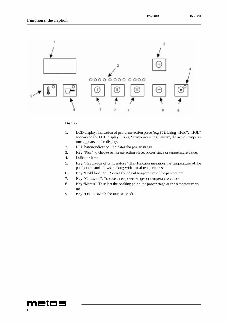
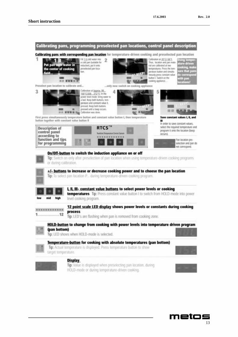
Display:
1. LCD display. Indication of pan preselection place (e.g.P7). Using “Hold”, “HOL”appears on the LCD display. Using “Temperature regulation”, the actual tempera-ture appears on the display.
2. LED baton-indication. Indicates the power stages.3. Key “Plus” to choose pan preselection place, power stage or temperature value.4. Indicator lamp.5. Key “Regulation of temperature” This function measures the temperature of the
pan bottom and allows cooking with actual temperatures.6. Key “Hold function”. Serves the actual temperature of the pan bottom.7. Key “Constants”. To save three power stages or temperature values.8. Key “Minus”. To select the cooking point, the power stage or the temperature val-
ue.9. Key “On” to switch the unit on or off.
6
17.6.2003 Rev. 2.0Operation instructions
4. Operation instructions
4.1 Before using the appliance
4.1.1 Operating test
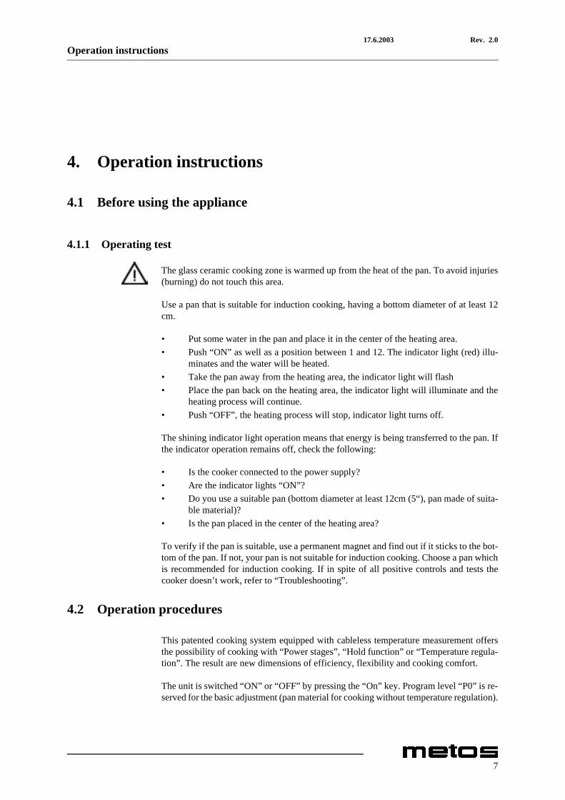
The glass ceramic cooking zone is warmed up from the heat of the pan. To avoid injuries(burning) do not touch this area.
Use a pan that is suitable for induction cooking, having a bottom diameter of at least 12cm.
• Put some water in the pan and place it in the center of the heating area.• Push “ON” as well as a position between 1 and 12. The indicator light (red) illu-
minates and the water will be heated.• Take the pan away from the heating area, the indicator light will flash• Place the pan back on the heating area, the indicator light will illuminate and the
heating process will continue.• Push “OFF”, the heating process will stop, indicator light turns off.
The shining indicator light operation means that energy is being transferred to the pan. Ifthe indicator operation remains off, check the following:
• Is the cooker connected to the power supply?• Are the indicator lights “ON”?• Do you use a suitable pan (bottom diameter at least 12cm (5“), pan made of suita-
ble material)?• Is the pan placed in the center of the heating area?
To verify if the pan is suitable, use a permanent magnet and find out if it sticks to the bot-tom of the pan. If not, your pan is not suitable for induction cooking. Choose a pan whichis recommended for induction cooking. If in spite of all positive controls and tests thecooker doesn’t work, refer to “Troubleshooting”.
4.2 Operation procedures
This patented cooking system equipped with cableless temperature measurement offersthe possibility of cooking with “Power stages”, “Hold function” or “Temperature regula-tion”. The result are new dimensions of efficiency, flexibility and cooking comfort.
The unit is switched “ON” or “OFF” by pressing the “On” key. Program level “P0” is re-served for the basic adjustment (pan material for cooking without temperature regulation).
7
17.6.2003 Rev. 2.0Operation instructions
4.2.1 Cooking with “Power stages”
Immediately after switching the unit “On”, it is ready for use. The shining LED baton in-dication signifies that energy is transmitted to the pan. By pressing the keys “+/-” the pow-er stages can be changed. The constants “low=I, mid=II and high=III” are preset and canbe changed by pressing the keys +/-. The inductive power transmission depends on theposition of the power stages (LED-display).
• LED position 1 > minimum power• LED position 12 > maximum power
By pressing the “On” key, the cooking process is stopped and the indication lamp is turnedoff.
4.2.2 Cooking with “Hold function”
The hold function serves to keep the actual temperature of the pan bottom. For the holdprocess, both calibrated and non-calibrated pans can be used. By pressing the key “Hold”,you can change from cooking with “power stages” into the “hold function”. The displayshows the sign “HOL”. In contrast to a cooking with power stages, the LED baton indi-cation shows only one shining LED. The hold function is used as a simple temperaturehold function where the temperature of the pan bottom is measured and kept contactless.This enables to keep the cooking process of the food on the required temperature for along time.
By pressing the key “+/-”, the temperature of the pan bottom is raised or dropped. Makesure that both hold and cooking process are watched by the kitchen staff. Especially thick-flowing food must be stired continously (danger of burning).
To change from the hold function into the cooking function: press the constants I, II or IIIfor a cooking with power regulation (see “Cooking with power stages”).
8
17.6.2003 Rev. 2.0Operation instructions
4.2.3 Cooking with “Temperature regulation”
With the temperature regulation function, the temperature of the pan bottom is measuredand enables to cook with an actual temperature indication on the display.
After selecting the pan location from the memory the power can be switched on. Move tothe “temperature reguleton” by pushing the “temperature” key and the display shows theactual temperature of the pan bottom.
The set point temperature can be set and changed by pushing either the key +/- or by press-ing the constants value buttons I, II or III. Often used temperatures can be saved in theconstant value buttons (see “Save of temperature constant”). By pressing the temperaturekey or changing the set-point value, the set-point value is indicated for two seconds. Aftertwo seconds, the actual value is shown on the display. In case of a non-calibrated pan withsimilar features as a calibrated pan on the pan preselection place, the measuring systemwill show incorrect temperature values. If the non-calibrated pan does not have similarcharasterstics, the temperature indication refuses to operate with a non-calibrated pan andchanges into the hold function (see”Unfinished calibration process”).
Make sure that both the hold process and the cooking process is watched by qualified per-sonell. Especially thick-flowing food must be stired continiously (danger of burning).
4.2.4 Choise of pan preselection place
When the unit is switched off, the pan preselection place can be chosen by pressing thekey “+/-”. On the display, the programmed cooking places P0 until P24 are indicated. Ablinking program point is either free or a calibration process has not been finished (see“Unfinished calibration process”). After choosing the preselection place, the unit can beswitched on.
4.2.5 Calibration of pans
Every pan has to be calibrated so that the actual temperature can be indicated on the LCDdisplay. Two calibration points are necessary: the first one at 20°C, the other is at 100°C.
4.2.6 Calibration process 20°C
1. For the calibration 20°C, the induction appliance has to be cold. If the ceran plateor coils are warmed up, an exact calibration process is not possible.
2. Check that the current is not on.3. Select the pan preselection place with the +/- buttons. A blinking program area is
either in use for calibration or a calibration process has not been finished. The plac-es P1-P24 can be chosen.
4. Fill 1 l water (temperature 20°C) into the cold pan and put it on the cooking point.5. Press key “temperature” and after this “I”. Keep both keys pressed at the same time
until you hear a beep signal.
9
17.6.2003 Rev. 2.0Operation instructions
4.2.7 Calibration process 100°C
1. If you are planning to calibrate several pans at the same time, make sure that thecalibration process 20°C has been done before for every pan (see “Calibrationprocess 20°C”).
2. Select the pan preselection place (P1-P24).3. Fill 1 l water into the pan and put it on the cooking point.4. Switch on the unit in the “power regulation process” and wait until the water boils
softly.5. Pressing the keys “+” and “-” you can correct the boiling condition until the water
boils softly and equally.6. First press “temperature” and after this, press “II”. Keep both keys pressed for 2
seconds until you hear a beep signal.
4.2.8 Unfinished calibration process
If the calibration process of a pan at 20°C and 100°C is not yet finished, a cooking processwith temperature regulation is not possible. The system changes automatically into thehold function.
4.2.9 Saving of temperature constant
1. For every pan, 3 temperature constants can be programmed.2. The unit must be in the mode “cooking with temperature regulation”.3. Adjust the temperature by pressing the keys “+” and “-”.4. Keep pressed the required constant key “I”, “II” or “III” for 2 seconds until you
hear the beep signal.
4.2.10 Indication of the actual temperature
In the temperature mode, the actual temperature is indicated on the display. If the displayindicates <___>, the pan detector is not able to recognize a pan. This indication can beindicated during the cooking process, when the pan is taken from the cooking zone (e.g.when using a sauteuse).
4.2.11 Indication of set-point temperature
By pressing the key “temperature”, the set-point temperature appears on the LCD displayfor 2 seconds.
10
17.6.2003 Rev. 2.0Operation instructions
4.3 After use
4.3.1 Cleaning
List with common types of soiling and recommendations how to treat them:
• Slight soiling, no burned residues: Wipe with a moist cloth (scotch), without clean-ing agent
• Sticky soiling: Remove with a scraper. Then wipe the heating area with a moistcloth
• Lime deposits, caused by water which has boiled over: These spots can be re-moved with vinegar or a special cleaning agent
• Sugar, sugar containing food, plastic, aluminum foil: Immediately scrape off thesugar, plastic or aluminum foil residues thoroughly from the hot cooking area, e.g.with a razor blade. After removal of the residues, clean it with a cleaning agent. Ifthe heating area soiled with residues of sugar, plastic or aluminum foil cools downwithout prior cleaning, the ceramic surface might become deformed by pinhead-sized pits
The cleaning of the Ceran plate and the ceramic bowl is identical to other similar surfaceslike glass. Do not use corrosive or abrasive cleaning agents, such as grill- and oven-sprays, stain- and rust-removers, scouring powder and rough sponges. Before beingcleaned, the Ceran plate or the ceramic bowl must be cooled down. Other maintenanceand servicing work other than cleaning as described here, must be done by authorizedservice personnel. Make sure that no liquid can enter in the induction unit.
4.3.2 Periodic service
A good maintenance of the induction cooker requires a regular cleaning, care and servic-ing. The operator has to ensure, that all components relevant for safety are in perfectworking order at all times. The cooker should be examined at least once a year by an au-thorized technician.
Do not open the cooker, dangerous electric voltage inside.
The cookers may only be opened by authorized personnel.
4.3.3 Out of operation
If the cooker is not in use, make sure that the current is off. If you don’t use the cooker fora longer period (several days) unplug the unit. Make sure that no liquid can enter into thecooker and do not clean the cooker with a jet of water.
11

17.6.2003 Rev. 2.0Short instruction
5. Short instruction
12
17.6.2003 Rev. 2.0Short instruction
13
17.6.2003 Rev. 2.0Short instruction
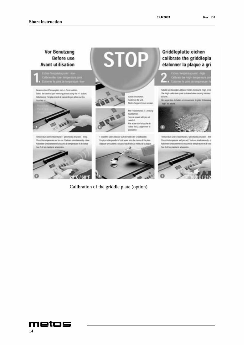
Calibration of the griddle plate (option)
14

17.6.2003 Rev. 2.0Installation
6. Installation
6.1 Preparing the installation
Please observe the following rules:
• Check and ensure that the supply voltage matches the voltage given on the ratingplate
• The electrical connections must satisfy local house installation regulations. Thevalid, national and local electrical regulations must be observed.
• This induction appliance is equipped with a cable which can be connected with thenecessary plug to the socket. The socket must be easily accessible to disconnectthe unit from the net.
• When faulty-current circuit breakers are used, they must be rated for a breakingcurrent of 30mA or more
• This induction unit is equipped with an air cooling system. Make sure that the airsupply and air exhaust are not blocked (wall, fabric etc)
• This induction unit is equipped with an additional grease filter. Make sure that theinduction unit does not take in hot ambiant air (concerns units standing side byside, or one behind the other, or standing near a frying pan or an oven)
• The induction unit must not be placed near or on a hot surface• The air intake temperature must be under 40°C• The operating staff has to make sure that installation is done by qualified person-
nel.
6.2 Installation
The cooker is equipped with a cable. It has to be connected to a wall socket. If no plug isinstalled at the cable, do the connection according to the information in “Electrical con-nections”. The installation for the electricity must be fittred by approved installation con-tractors in accordance with specific national and local regulations. The installationcontractors are responsible for the correct layout and installation in conformity with allsafety regulations. The warning signs and rating plates put up to the appliances muststrictly be followed. Check and ensure, that the mains voltage matches with the voltagegiven on the rating plate.
The cooker must always be installed on a clean and even surface (table, base, etc.) at it’sdesignated site. The cooker stands on non-slip rubber feet and is not permanently in-stalled. It must be installed in such a way that it cannot fall down or move in a unevenposition. The conditions for the “positioning the appliance must be guaranteed.
Put “OFF” on the key pad before connecting the cooker with the voltage supply.
15
17.6.2003 Rev. 2.0Installation
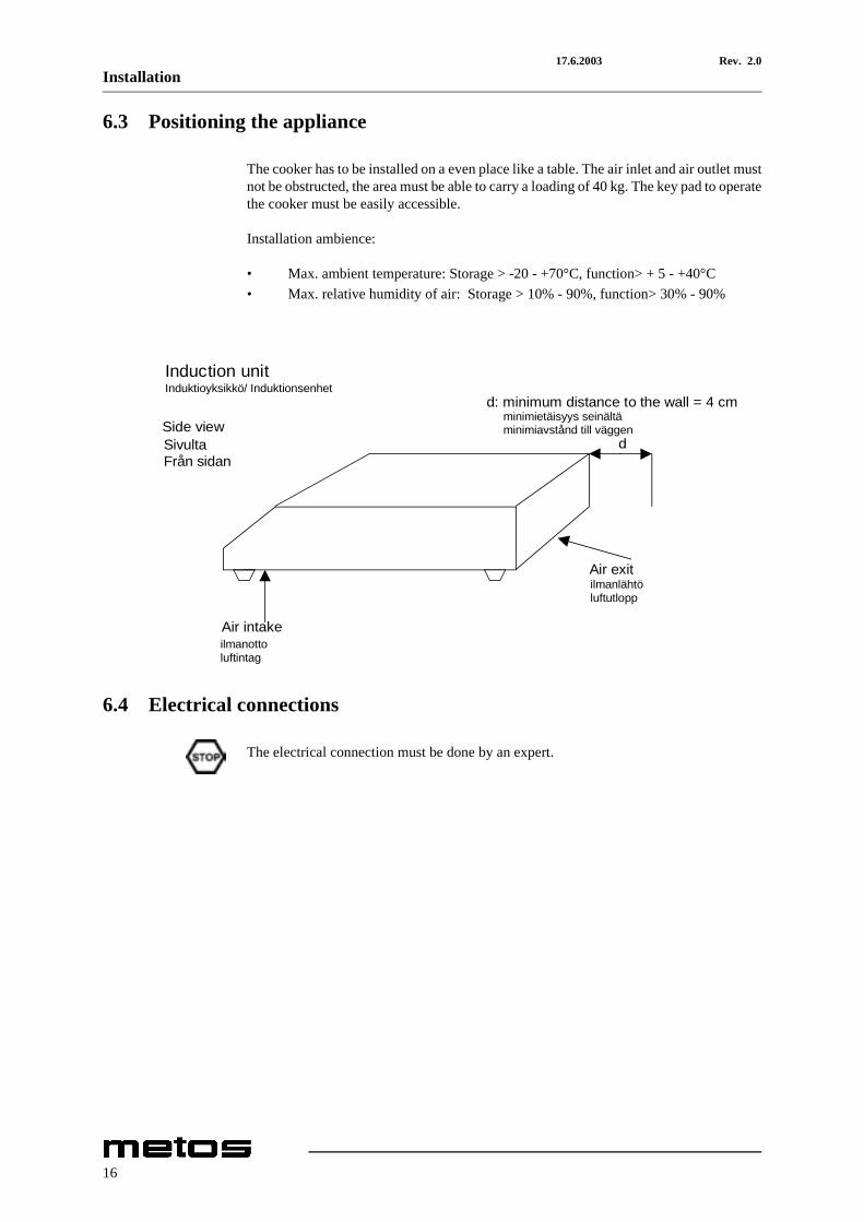
6.3 Positioning the appliance
The cooker has to be installed on a even place like a table. The air inlet and air outlet mustnot be obstructed, the area must be able to carry a loading of 40 kg. The key pad to operatethe cooker must be easily accessible.
Installation ambience:
• Max. ambient temperature: Storage > -20 - +70°C, function> + 5 - +40°C• Max. relative humidity of air: Storage > 10% - 90%, function> 30% - 90%
6.4 Electrical connections
The electrical connection must be done by an expert.
Induction unit
Side view
d: minimum distance to the wall = 4 cm
SivultaFrån sidan
d
Air exit
Air intake
Induktioyksikkö/ Induktionsenhet
minimietäisyys seinältäminimiavstånd till väggen
ilmanlähtöluftutlopp
ilmanottoluftintag
16
17.6.2003 Rev. 2.0Installation
6.4.1 Single phase supply
Induction appliance: Type Multi-Line 3500. The cooker is equipped with a cable con-forming to the national regulations.
Make sure that the plug is connected the right way:
• Phase: brown (Colour of the conductor)• Neutral: blue (Colour of the conductor)• Protective ground: green-yellow (Colour of the conductor)
If the voltage is wrong, the cooker can be damaged.
• Voltage: +6 / -10%• Frequency: 50 Hz / 60 Hz• Preliminary fuse: 16A
6.4.2 Three phase supply
Induction appliance:Model Multi-Line 5500. The cookers are equipped with a cable con-forming to the national regulations.
Make sure that the plug is connected the right way:
• Phase 1,2,3: black / brown/blue (Colour of the conductor) or other colours, exceptof grey, green or white
• Protective ground: green / yellow (Colour of the conductor)
If the voltage is wrong, the cooker can be damaged.
• Voltage: + 6 / -10 %• Frequency: 50 / 60 Hz• Preliminary fuse: 10A
17
17.6.2003 Rev. 2.0Installation
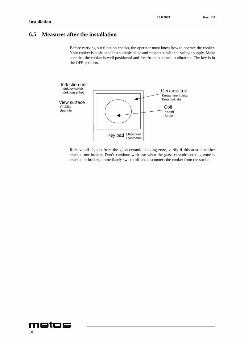
6.5 Measures after the installation
Before carrying out function checks, the operator must know how to operate the cooker.Your cooker is positioned in a suitable place and connected with the voltage supply. Makesure that the cooker is well positioned and free from exposure to vibration. The key is inthe OFF-position.
Remove all objects from the glass ceramic cooking zone, verify if this area is neithercracked nor broken. Don’t continue with use when the glass ceramic cooking zone iscracked or broken, immediately switch off and disconnect the cooker from the socket.
Induction unit
Ceramic top
View surface
Coil
Key pad
InduktioyksikköInduktionsenhet
YlhäältäUppifrån
Keraaminen pintaKeramisk yta
KäämiSpole
EtupaneeliFrontpanel
18
17.6.2003 Rev. 2.0Technical specifications
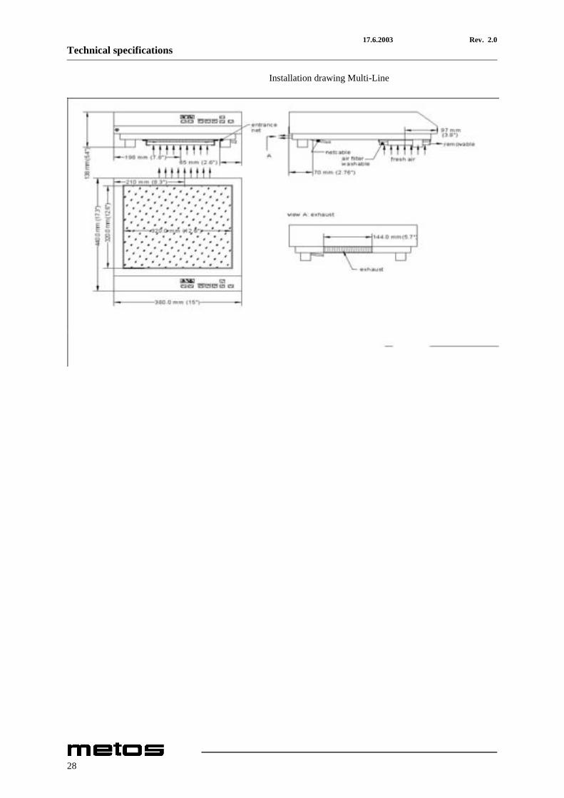
8. Technical specifications
Installation drawing Multi-Line
27
17.6.2003 Rev. 2.0Technical specifications
Installation drawing Multi-Line
28

17.6.2003 Rev. 2.0Technical specifications
Item Type Specification
Lamp 24V DC/max. 40mA (red)Key pad and LED display
Dimensions WxDxH 380x440x138 mmCeramic top 320x320 mm
Technical dataVoltage 3500 230VVoltage 5500 400VPower 3500 3,5kWPower 5500 5,0kWWeight 3500 11 kgWeight 5500 11 kg
Operation conditionsMax. tolerance of the nominal supply +6/-10%Supply frequency 50/60 HzProtection class IP X0
29

17.6.2003 Rev. 2.0Technical specifications
30
17.6.2003 Rev. 2.0Technical specifications
31
17.6.2003 Rev. 2.0Technical specifications
32

17.6.2003 Rev. 2.0Technical specifications
33