Embed Size (px)
Citation preview
Proceedings of ASME 2010 3rd Joint US-European Fluids Engineering Summer Meeting and 8th International Conference on Nanochannels, Microchannels, and Minichannels
FEDSM2010-ICNMM2010 August 1-5, 2010, Montreal, Canada
FEDSM-ICNMM2010-30613
MULTI OBJECTIVE SHAPE OPTIMIZATION OF A LOW SPECIFIC SPEED IMPELLER FOR A ROCKET ENGINE TURBOPUMP
Naoki Tani JAPAN Aerospace Exploration Agency
Tsukuba, Ibaraki, JAPAN
Noriyuki Shimiya IHI Corporation
Nishitama-gun, Tokyo, JAPAN
Yoshiki Yoshida JAPAN Aerospace Exploration Agency
Kakuda, Miyagi, JAPAN
Nobuhiro Yamanishi JAPAN Aerospace Exploration Agency
Tsukuba, Ibaraki, JAPAN
ABSTRACT A rocket engine should be small and low weight, a
turbopump for a rocket engine must be smaller and have higher rotation speed than the conventional pumps. However, to achieve high thrust, pump discharge pressure must be high enough. As a result, a low specific speed impeller is often chosen for a rocket engine impeller. Generally speaking, efficiency of such a low specific speed impeller is lower since blade loading becomes high and large scale secondary flow will likely occur especially around the trailing edge. Therefore, to clarify the high efficiency shape, multi objective optimization of low specific speed impeller was carried out in the present study.
The optimized result showed that there is a strong tradeoff between head and efficiency, and this tendency is not influenced by the flow rate. This means that performance dependency by a flow rate may be small by such a low specific speed impeller. Shape comparison between efficiency and head optimum results showed that not only outlet blade angle but also inlet blade angle are important for high efficiency impeller. By modifying these two blade angles, blade loading distribution is changed and blockage by secondary flow region is changed. As a result, for the high head impeller, large scales blockage occurs at the trailing edge, however, for the efficiency optimum result, blockage near the trailing edge becomes smaller.
INTRODUCTION In order to achieve high-efficiency and high-robustness
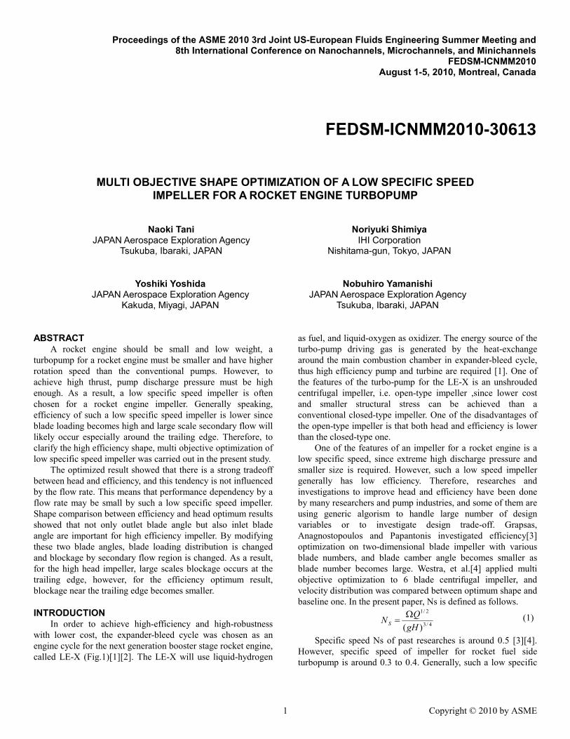
with lower cost, the expander-bleed cycle was chosen as an engine cycle for the next generation booster stage rocket engine, called LE-X (Fig.1)[1][2]. The LE-X will use liquid-hydrogen
as fuel, and liquid-oxygen as oxidizer. The energy source of the turbo-pump driving gas is generated by the heat-exchange around the main combustion chamber in expander-bleed cycle, thus high efficiency pump and turbine are required [1]. One of the features of the turbo-pump for the LE-X is an unshrouded centrifugal impeller, i.e. open-type impeller ,since lower cost and smaller structural stress can be achieved than a conventional closed-type impeller. One of the disadvantages of the open-type impeller is that both head and efficiency is lower than the closed-type one.
One of the features of an impeller for a rocket engine is a low specific speed, since extreme high discharge pressure and smaller size is required. However, such a low speed impeller generally has low efficiency. Therefore, researches and investigations to improve head and efficiency have been done by many researchers and pump industries, and some of them are using generic algorism to handle large number of design variables or to investigate design trade-off. Grapsas, Anagnostopoulos and Papantonis investigated efficiency[3] optimization on two-dimensional blade impeller with various blade numbers, and blade camber angle becomes smaller as blade number becomes large. Westra, et al.[4] applied multi objective optimization to 6 blade centrifugal impeller, and velocity distribution was compared between optimum shape and baseline one. In the present paper, Ns is defined as follows.
4/3
2/1
)(gHQNS
Ω= (1)
Specific speed Ns of past researches is around 0.5 [3][4]. However, specific speed of impeller for rocket fuel side turbopump is around 0.3 to 0.4. Generally, such a low specific
1 Copyright © 2010 by ASME
Proceedings of the ASME 2010 3rd Joint US-European Fluids Engineering Summer Meeting and 8th International Conference on Nanochannels, Microchannels, and Minichannels
FEDSM-ICNMM2010 August 1-5, 2010, Montreal, Canada
FEDSM-ICNMM2010-30613
speed impeller has low efficiency due to large scale separation at the suction side of the blade[4]. Avoiding the separation is quite difficult because of a high blade loading, and efficiency improvement is also difficult. However, knowing the shape tendency with higher efficiency is still important since both head and shaft-power are large and reducing shaft-power can improve total performance of a rocket engine. Therefore, in the present study, multi-objective optimization was applied to low-specific speed impeller. The objective of the research is to clarify the trade-off information about impeller blade shape against efficiency and head. Especially, since there is little knowledge for high-performance open-impeller design, impeller with tip-clearance was chosen as a baseline shape of the present design optimization. Multi objective generic algorism (MOGA) was applied as an optimizer, and some statistical process was used to clarify the trade-off information.
Open Impeller
Turbo-Pump
LE-X Engine Figure 1. THE LE-X ENGINE AND TURBO-PUMP WITH
AN OPEN-TYPE IMPELLER.
NOMENCLATURE CL: Blade Loading Coefficient
2
22
....
uPPC SSSP
L ρ−
=
Cp: Pressure Coefficient
2
22uPPC in
p ρ−
=
Cpsa: Pressure Fluctuation Coefficient
2
22u
PPC Average
psa ρ−
=
g: Gravity Acceleration
H: Head g
PPH inout
ρ−
=
N: Rotation Speed in RPM Ns: Specific Speed P: Pressure Q: Volumetric Flow Rate R: Radius Rtip : Tip Radius T: Torque U: Relative Flow Velocity Urad: Radial Flow Velocity Utip: Tip Velocity u2: Impeller Outlet Rotational Velocity Ω: Rotation Speed in rad./sec. ρ: Density τ: Pitch Angle τpitch : Pitch Angle of a Passage Suffix Average: Averaged Value in: Inlet out: Outlet P.S. : Pressure Surface S.S. : Suction Surface
OPTIMIZATION METHOD The optimization method for the present study is a real-
coded multi-objective generic algorithm with constraint-handling method by Oyama et al.[5]. One of the features of this method is that it is more efficient and more robust on searching the optimized solution with multiple constraints. The parameters of MOGA are listed in Table 1. A Best-N selection with sharing and Pareto-ranking method was applied. A Selection method was SUS method, and crossover method was BLX-0.5. One of the disadvantages of MOGA is a large computational cost, and sometimes it requires more than 1000 CFD runs. To reduce such a extremely high computational cost, Jeong[6] combined the Kriging interpolation method with MOGA. The Kriging method is used as a response surface, and MOGA optimization is done on that response surface. This method is quite effective to reduce computational cost, and number of CFD runs can be reduced from thousands to handreds. Therefore, in the present optimization, MOGA with the Kriging interpolation was used. Overall optimization procedure is shown in Fig.2.
2 Copyright © 2010 by ASME
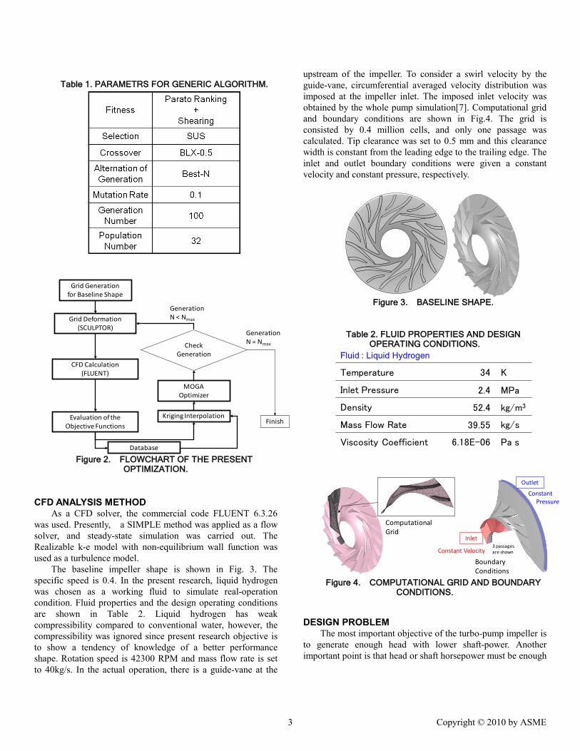
Table 1. PARAMETRS FOR GENERIC ALGORITHM.
Grid Generationfor Baseline Shape
MOGAOptimizer
Grid Deformation(SCULPTOR)
CFD Calculation(FLUENT)
Check Generation
FinishEvaluation of theObjective Functions
GenerationN = Nmax
Database
Kriging Interpolation
GenerationN < Nmax
Figure 2. FLOWCHART OF THE PRESENT
OPTIMIZATION.
CFD ANALYSIS METHOD As a CFD solver, the commercial code FLUENT 6.3.26
was used. Presently, a SIMPLE method was applied as a flow solver, and steady-state simulation was carried out. The Realizable k-e model with non-equilibrium wall function was used as a turbulence model.
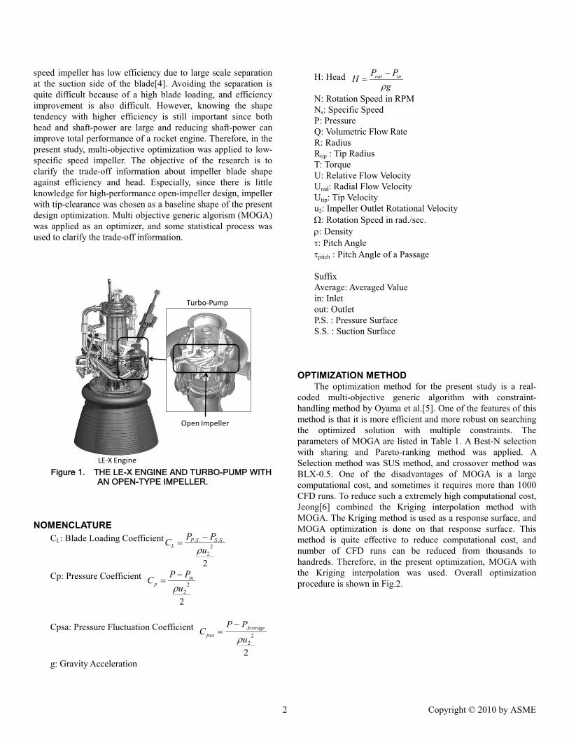
The baseline impeller shape is shown in Fig. 3. The specific speed is 0.4. In the present research, liquid hydrogen was chosen as a working fluid to simulate real-operation condition. Fluid properties and the design operating conditions are shown in Table 2. Liquid hydrogen has weak compressibility compared to conventional water, however, the compressibility was ignored since present research objective is to show a tendency of knowledge of a better performance shape. Rotation speed is 42300 RPM and mass flow rate is set to 40kg/s. In the actual operation, there is a guide-vane at the
upstream of the impeller. To consider a swirl velocity by the guide-vane, circumferential averaged velocity distribution was imposed at the impeller inlet. The imposed inlet velocity was obtained by the whole pump simulation[7]. Computational grid and boundary conditions are shown in Fig.4. The grid is consisted by 0.4 million cells, and only one passage was calculated. Tip clearance was set to 0.5 mm and this clearance width is constant from the leading edge to the trailing edge. The inlet and outlet boundary conditions were given a constant velocity and constant pressure, respectively.
Figure 3. BASELINE SHAPE.
Table 2. FLUID PROPERTIES AND DESIGN OPERATING CONDITIONS.
Fluid : Liquid Hydrogen
Temperature 34 K
Inlet Pressure 2.4 MPa
Density 52.4 kg/m3
Mass Flow Rate 39.55 kg/s
Viscosity Coefficient 6.18E-06 Pa s
Boundary Conditions
3 passages are shown
Inlet
Outlet
Constant Velocity
Constant Pressure
Computational Grid
Figure 4. COMPUTATIONAL GRID AND BOUNDARY
CONDITIONS.
DESIGN PROBLEM The most important objective of the turbo-pump impeller is
to generate enough head with lower shaft-power. Another important point is that head or shaft horsepower must be enough
3 Copyright © 2010 by ASME
high within the operation range, therefore, following four points were chosen as an objective functions.
Objective Functions Efficiency maximum at 100% flow rate Head maximum at 100% flow rate Efficiency maximum at 80% flow rate Head maximum at 80% flow rate
Definition of efficiency is as follows:
QTNPP inout
602πη −
= (2)
To maintain geometrical consistency, following two constraint functions are used.
Constraint Functions Impeller diameter is less than the baseline shape Outlet blade height is constant
The design variables are defined as control points which are placed around the grid, and these control points are moved to deform the shape by SCULPTOR, which is a commercial mesh morphing software. The control point locations are shown in Fig.5. There are 10 control points, and each control point moves in the axial, radial and circumferential direction. Moving distance of each direction is shown in Table.3, and total number of design variables is 30.
In the present optimization, updating of the Kriging response surface interpolation was done 20 times with 16 points, and MOGA was done on the response surface by 100 generations with 16 populations at each update. As a result, total number of CFD analysis is 320.
33
3
33
3
3
3
33
Meridional Plane
View fromthe Inlet
30 design variables
Hub
Rotation
Moving DirectionAxial
RadialCircumferential
Small numbers means a degree of freedom of each control point
Hub
Figure 5. CONTROL POINTS OF THE DESIGN
VARIABLES.
Table 3. MOVING DIATANCE OF EACH DIRECTION.
Axial Direction ±2mm
Radial Direction ±3mm
Circumferential Direction ±12degree
OPTIMIZED RESULT
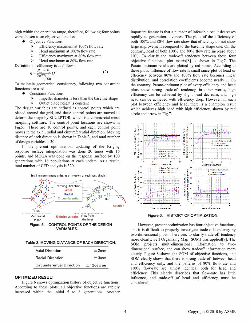
Figure 6 shows optimization history of objective functions. According to these plots, all objective functions are rapidly increased within the initial 5 to 6 generations. Another
important feature is that a number of infeasible result decreases rapidly as generation advances. The plots of the efficiency of both 100% and 80% flow rate show that efficiency do not show large improvement compared to the baseline shape one. On the contrary, head of both 100% and 80% flow rate increase about 10%. To clarify the trade-off tendency between these four objective functions, plot matrix[8] is shown in Fig.7. The Parato-optimum results are plotted by red points. According to these plots, influence of flow rate is small since plot of head or efficiency between 80% and 100% flow rate becomes linear distribution, and correlation coefficients become nearly 1. On the contrary, Parato-optimum plot of every efficiency and head plots show strong trade-off tendency, in other words, high efficiency can be achieved by slight head decrease, and high head can be achieved with efficiency drop. However, in each plot between efficiency and head, there is a champion result which achieves high head with high efficiency, shown by red circle and arrow in Fig.7.
Figure 6. HISTORY OF OPTIMIZATION. However, present optimization has four objective functions,
and it is difficult to properly investigate trade-off tendency by two-dimensional plots. Therefore, to clarify trade-off tendency more clearly, Self Organizing Map (SOM) was applied[9]. The SOM projects multi-dimensional information to two-dimensional surface, and can show tradeoff information more clearly. Figure 8 shows the SOM of objective functions, and SOM clearly shows that there is strong trade-off between head and efficiency only, and the patterns of 80% flow-rate and 100% flow-rate are almost identical both for head and efficiency. This clearly describes that flow-rate has little influence, and trade-off of head and efficiency must be considered.
4 Copyright © 2010 by ASME
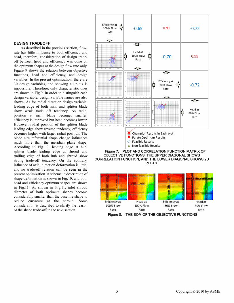
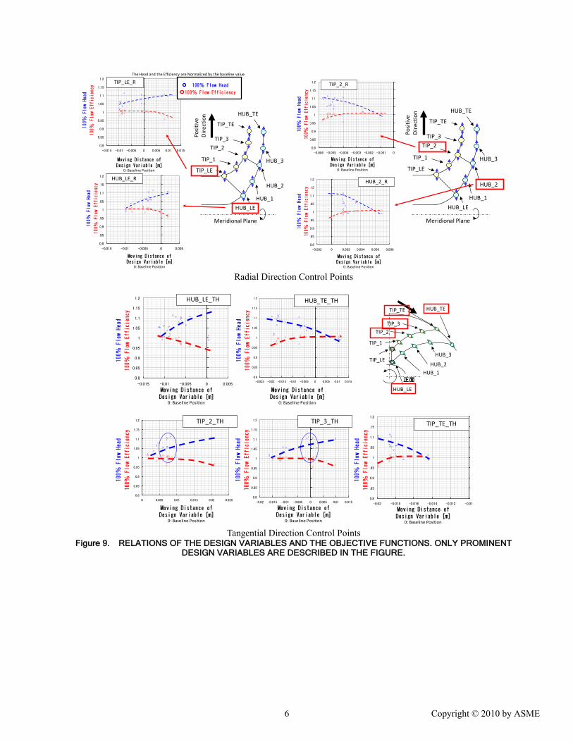
DESIGN TRADEOFF As described in the previous section, flow-
rate has little influence to both efficiency and head, therefore, consideration of design trade-off between head and efficiency was done on the optimum shapes at the design flow rate only. Figure 9 shows the relation between objective functions, head and efficiency, and design variables. In the present optimization, there are 30 design variables, and showing all plots is impossible. Therefore, only characteristic ones are shown in Fig.9. In order to distinguish each design variable, design variable names are also shown. As for radial direction design variable, leading edge of both main and splitter blade show weak trade off tendency. As radial position at main blade becomes smaller, efficiency is improved but head becomes lower. However, radial position of the splitter blade leading edge show reverse tendency, efficiency becomes higher with larger radial position. The blade circumferential shape change influences much more than the meridian plane shape. According to Fig. 9, leading edge at hub, splitter blade leading edge at shroud and trailing edge of both hub and shroud show strong trade-off tendency. On the contrary, influence of axial direction deformation is little, and no trade-off relation can be seen in the present optimization. A schematic description of shape deformation is shown in Fig.10, and both head and efficiency optimum shapes are shown in Fig.11. As shown in Fig.11, inlet shroud diameter of both optimum shapes become considerably smaller than the baseline shape to reduce curvature at the shroud. Some consideration is described to clarify the reason of the shape trade-off in the next section.
Efficiency at100% Flow
Rate
Head at 100% Flow
Rate
Efficiency at80% Flow
Rate
Head at80% Flow
Rate
0.8
0.9
1
1.1
1.2
1.3
1.4
1.5
0.8 0.85 0.9 0.95 1 1.05 1.1
0.8
0.85
0.9
0.95
1
1.05
0.8 0.85 0.9 0.95 1 1.05 1.1
0.8
0.9
1
1.1
1.2
1.3
1.4
1.5
0.8 0.85 0.9 0.95 1 1.05 1.1
0.8
0.85
0.9
0.95
1
1.05
0.8 0.9 1 1.1 1.2 1.3 1.4 1.5
流揚程
0.8
0.9
1
1.1
1.2
1.3
1.4
1.5
0.8 0.9 1 1.1 1.2 1.3 1.4 1.5
0.8
0.85
0.9
0.95
1
1.05
0.8 0.9 1 1.1 1.2 1.3 1.4 1.5
流量揚程
0.91-0.65 -0.72
-0.70 0.99
-0.72
Champion Results in Each plotParato Optimum ResultsFeasible ResultsNon-feasible Results
Figure 7. PLOT AND CORRELATION FUNCTION MATRIX OF
OBJECTIVE FUNCTIONS. THE UPPER DIAGONAL SHOWS CORRELATION FUNCTION, AND THE LOWER DIAGONAL SHOWS 2D
PLOTS.
Efficiency at100% Flow
Rate
Head at 100% Flow
Rate
Efficiency at80% Flow
Rate
Head at80% Flow
Rate
Figure 8. THE SOM OF THE OBJECTIVE FUNCTIONS
5 Copyright © 2010 by ASME
0.8
0.85
0.9
0.95
1
1.05
1.1
1.15
1.2
-0.015 -0.01 -0.005 0 0.005 0.01 0.015
TIP_LE_R
Moving Distance of Design Variable [m]
0: Baseline Position
The Head and the Efficiency are Normalized by the baseline value
100%
Flow Head
100%
Flow Efficiency 100% Flow Head
100% Flow Efficiency
Meridional Plane
HUB_LE
HUB_1
HUB_2
HUB_3
HUB_TE
TIP_TE
TIP_3TIP_2
TIP_1
TIP_LE
Posi
tive
Dir
ectio
n
0.8
0.85
0.9
0.95
1
1.05
1.1
1.15
1.2
-0.015 -0.01 -0.005 0 0.005
HUB_LE_R
100%
Flow Head
100%
Flow Efficiency
Moving Distance of Design Variable [m]
0: Baseline Position
0.8
0.85
0.9
0.95
1
1.05
1.1
1.15
1.2
-0.006 -0.005 -0.004 -0.003 -0.002 -0.001 0
TIP_2_R
Moving Distance of Design Variable [m]
0: Baseline Position
100%
Flow Head
100%
Flow Efficiency
Meridional Plane
HUB_LE
HUB_1
HUB_2
HUB_3
HUB_TE
TIP_TE
TIP_3TIP_2
TIP_1
TIP_LE
Posi
tive
Dir
ectio
n
0.8
0.85
0.9
0.95
1
1.05
1.1
1.15
1.2
-0.002 0 0.002 0.004 0.006 0.008
Moving Distance of Design Variable [m]
0: Baseline Position
HUB_2_R
100%
Flow Head
100%
Flow Efficiency
Radial Direction Control Points
0.8
0.85
0.9
0.95
1
1.05
1.1
1.15
1.2
-0.015 -0.01 -0.005 0 0.005
HUB_LE_TH
0.8
0.85
0.9
0.95
1
1.05
1.1
1.15
1.2
0 0.005 0.01 0.015 0.02 0.025
TIP_2_TH
0.8
0.85
0.9
0.95
1
1.05
1.1
1.15
1.2
-0.02 -0.015 -0.01 -0.005 0 0.005 0.01 0.015
TIP_3_TH
正面
HUB_LE
HUB_1HUB_2
HUB_3
HUB_TETIP_TE
TIP_3TIP_2
TIP_1
TIP_LE
Moving Distance of Design Variable [m]
0: Baseline Position
Moving Distance of Design Variable [m]
0: Baseline Position
Moving Distance of Design Variable [m]
0: Baseline Position
100%
Flow Head
100%
Flow Efficiency
100%
Flow Head
100%
Flow Efficiency
100%
Flow Head
100%
Flow Efficiency
0.8
0.85
0.9
0.95
1
1.05
1.1
1.15
1.2
-0.02 -0.018 -0.016 -0.014 -0.012 -0.01
TIP_TE_TH
100%
Flow Head
100%
Flow Efficiency
100%
Flow Head
100%
Flow Efficiency
0.8
0.85
0.9
0.95
1
1.05
1.1
1.15
1.2
-0.025 -0.02 -0.015 -0.01 -0.005 0 0.005 0.01 0.015
HUB_TE_TH
Moving Distance of Design Variable [m]
0: Baseline Position
Moving Distance of Design Variable [m]
0: Baseline Position Tangential Direction Control Points
Figure 9. RELATIONS OF THE DESIGN VARIABLES AND THE OBJECTIVE FUNCTIONS. ONLY PROMINENT DESIGN VARIABLES ARE DESCRIBED IN THE FIGURE.
6 Copyright © 2010 by ASME
1
2
3
4
Increase HeadIncrease Efficiency
1. Radius of Blade Leading Edge2. Radius of Splitter Blade Leading Edge
3. Inlet Blade Angle4. Outlet Blade Angle
Figure 10. SCHEMATIC DESCRIPTION OF TRADE-OFF
SHAPE DEFORMATION
00.32
1.00
0.50
0.25
0.75
0.00
X/Rtip
R/R t
ip
Q/Qd=100% Efficiency Maximum
Baseline Q/Qd=100% Head Maximum
Q/Qd=100% Head MaximumQ/Qd=100% Efficiency MaximumGray color is the baseline shape
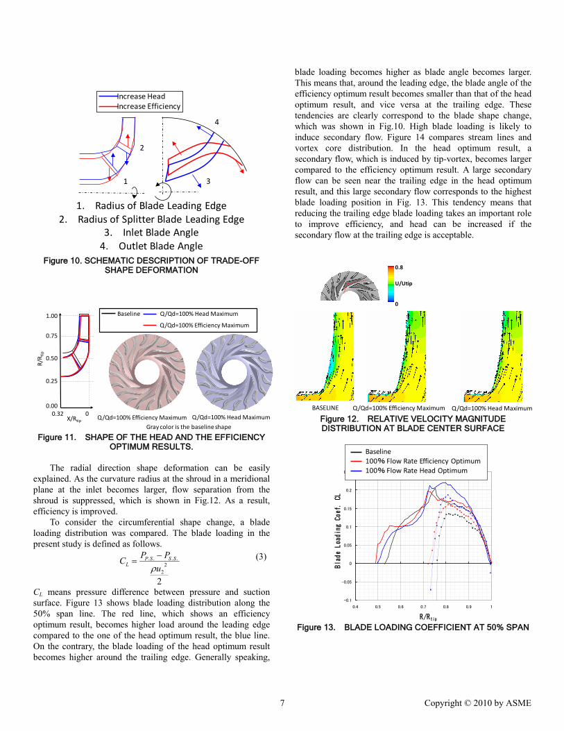
Figure 11. SHAPE OF THE HEAD AND THE EFFICIENCY OPTIMUM RESULTS.
The radial direction shape deformation can be easily
explained. As the curvature radius at the shroud in a meridional plane at the inlet becomes larger, flow separation from the shroud is suppressed, which is shown in Fig.12. As a result, efficiency is improved.
To consider the circumferential shape change, a blade loading distribution was compared. The blade loading in the present study is defined as follows.
2
22
....
uPPC SSSP
L ρ−
= (3)
CL means pressure difference between pressure and suction surface. Figure 13 shows blade loading distribution along the 50% span line. The red line, which shows an efficiency optimum result, becomes higher load around the leading edge compared to the one of the head optimum result, the blue line. On the contrary, the blade loading of the head optimum result becomes higher around the trailing edge. Generally speaking,
blade loading becomes higher as blade angle becomes larger. This means that, around the leading edge, the blade angle of the efficiency optimum result becomes smaller than that of the head optimum result, and vice versa at the trailing edge. These tendencies are clearly correspond to the blade shape change, which was shown in Fig.10. High blade loading is likely to induce secondary flow. Figure 14 compares stream lines and vortex core distribution. In the head optimum result, a secondary flow, which is induced by tip-vortex, becomes larger compared to the efficiency optimum result. A large secondary flow can be seen near the trailing edge in the head optimum result, and this large secondary flow corresponds to the highest blade loading position in Fig. 13. This tendency means that reducing the trailing edge blade loading takes an important role to improve efficiency, and head can be increased if the secondary flow at the trailing edge is acceptable.
0
0.8
U/Utip
BASELINE Q/Qd=100% Efficiency Maximum Q/Qd=100% Head Maximum Figure 12. RELATIVE VELOCITY MAGNITUDE DISTRIBUTION AT BLADE CENTER SURFACE
-0.1
-0.05
0
0.05
0.1
0.15
0.2
0.25
0.4 0.5 0.6 0.7 0.8 0.9 1
R/Rtip
Blade Loading Coef. CL
Baseline100% Flow Rate Efficiency Optimum100% Flow Rate Head Optimum
Figure 13. BLADE LOADING COEFFICIENT AT 50% SPAN
7 Copyright © 2010 by ASME
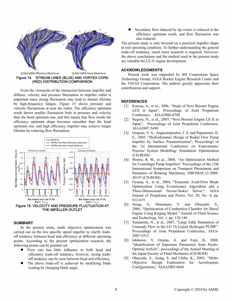
Q/Qd=100% Efficiency Maximum Q/Qd=100% Head Maximum Figure 14. STREAM LINES (BLUE) AND VORTEX CORE
(RED) DISTRIBUTION COMPARISON From the viewpoint of the interaction between impeller and
diffuser, velocity and pressure fluctuation at impeller outlet is important since strong fluctuation may lead to shorter lifetime by high-frequency fatigue. Figure 15 shows pressure and velocity fluctuations at near the outlet. The efficiency optimum result shows smaller fluctuation both in pressure and velocity than the head optimum one, and this means that flow inside the efficiency optimum shape becomes smoother than the head optimum one, and high efficiency impeller may achieve longer lifetime by reducing flow fluctuation.
0
0.05
0.1
0.15
0.2
0.25
0.3
0.35
0 1 2 3
Non-dimensionalized Pitch Angle τ/τpitch
Non-Dimensionalized Radial Velocity
Urad/Utip
3 Pitches are Shown
Blade Splitter
Pressure Fluctuation Coef.
Cpsa
-0.015
-0.01
-0.005
0
0.005
0.01
0.015
0.02
0 1 2 3
Blade SplitterBlade Splitter
Baseline100% Flow Rate Efficiency Optimum100% Flow Rate Head Optimum
Blade SplitterBlade SplitterBlade Splitter
Non-dimensionalized Pitch Angle τ/τpitch
3 Pitches are Shown
Figure 15. VELOCITY AND PRESSURE FLUCTUATION AT
THE IMPELLER OUTLET
SUMMARY In the present study, multi objective optimization was
carried out on the low specific speed impeller to clarify trade-off tendency between head and efficiency at different operating points. According to the present optimization research, the following points can be pointed out.
Flow rate has little influence to both head and efficiency trade-off tendency, however, strong trade-off tendency can be seen between head and efficiency.
The above trade-off is achieved by modifying blade loading by changing blade angle.
Secondary flow induced by tip-vortex is reduced in the efficiency optimum result, and flow fluctuation was also reduced.
The present study is only focused on a practical impeller shape at real operating condition. To further understanding the general trade-off tendency, much more research is required. However, the above conclusions and the method used in the present study are valuable for LE-X engine development.
ACKNOWLEDGMENTS Present work was supported by IHI Corporation Space
Technology Group, JAXA Rocket Engine Research Center and the VINAS Corporation. The authors greatly appreciate their contributions and support.
REFERENCES [1] Kurosu, A., et al., 2006, “Study of Next Booster Engine
LEX in Japan”, Proceedings of Joint Propulsion Conference, AIAA2006-4700
[2] Negoro, N., et al., 2007, “Next Booster Engine LE-X in Japan”, Proceedings of Joint Propulsion Conference, AIAA2007-5490
[3] Grapsas, V. A., Angnostopoulos, J. S. and Papantonis, D. E., 2005, “Hydrodynamic Design of Radial Flow Pump Impeller by Surface Parametrization”, Proceedings of the 1st International Conference on Experiments/ Process/ System Modelling/ Simulation/ Optimization (CD-ROM)
[4] Westra, R. W., et al., 2008, “An Optimization Method for Centrifugal Pump Impellers” Proceedings of the 12th International Symposium on Transport Phenomena and Dynamics of Rotating Machinery, ISROMAC12-2008-20147 (CD-ROM).
[5] Oyama, A., et al., 2004, "Transonic Axial-Flow Blade Optimization Using Evolutionary Algorithms and a Three-Dimensional Navier-Stokes Solver," AIAA Journal of Propulsion and Power, Vol. 20, No. 4, pp. 612-619
[6] Jeong, S., Minemura, Y. and Obayashi, S., 2006, ”Optimization of Combustion Chamber for Diesel Engine Using Kriging Model,” Journal of Fluid Science and Technology, Vol. 1, pp. 138-146
[7] Yamanishi, N., et al., 2007, “Large Eddy Simulation of Unsteady Flow in the LE-7A Liquid Hydrogen PUMP”, Proceedings of Joint Propulsion Conference, AIAA-2007-5515
[8] Ishikawa, Y, Oyama, A. and Fujii, K, 2008, “Identification of Important Parameters from Pareto-Optimal Airfoils”, proceedings of the Annual Meeting of the Japan Society of Fluid Mechanics (CD-ROM)
[9] Obayashi, S., Jeong, S. and Chiba, K., 2005, “Multi-Objective Design Exploration for Aerodynamic Configurations,” AIAA2005-4666
8 Copyright © 2010 by ASME