Embed Size (px)
Citation preview

Indian Journal of Engineering & Materials Sciences Vol. 25, October 2018, pp. 383-390
Multi-performance optimization of micro-drilling using Taguchi technique based on membership function
K Shunmugesha & K Panneerselvamb* aDepartment of Mechanical Engineering, Viswajyothi College of Engineering and Technology, Vazhakulam 686 670, India
bDepartment of Production Engineering, National Institute of Technology, Tiruchirappalli 620 015, India
Received 13 January 2016; accepted 31 August 2017
Carbon fibre reinforced polymers (CFRP) tends to be employed in the manufacture of aerospace industry, construction and costly sports cars, wherever robust and lightweight materials are needed. The present aims to evaluate and optimize the micro-drilling machining process on carbon fibre reinforced polymer composite material in terms of multiple performance characteristics of circularity and cylindricity errors. Micro-drilling tests based on Taguchi L27 orthogonal array are carried out on CFRP laminates under varying cutting conditions of spindle speed, feed rate and drill diameters. The process outcomes are assessed in-terms of circularity and cylindricity errors. The influence and percentage contribution of process parameters are examined by analysis of variance (ANOVA). Taguchi methodology supported by membership function is used for the optimization of the multiple responses transformed to the output of signal-to-noise (S/N) ratio. The scope of the experimental design is to minimize circularity and cylindricity errors simultaneously. Confirmation tests are performed to verify the effectiveness of the proposed hybrid approach.
Keywords: Micro-drilling, Carbon fibre reinforced polymer, Taguchi technique, Membership function, Circularity error, Cylindricity error
Fibre reinforced polymer (FRP) composite materials by virtue of their high strength-weight ratio, durability and high corrosion resistance, tend to replace the conventional materials as a better alternative in a variety of commercial, domestic and engineering applications. The high strength-to-weight ratio of the material will lead to lighter structural components. The material behaviour depends on the fibre reinforcement content, fibre orientation, and type of resin used. The fastening of components made of FRP composite materials through drilling is extensively done in fabrication of sub-assemblies and assemblies for FRP structures1. Carbon fibre reinforced polymer, contains carbon fibres as reinforcing element of the matrix. Carbon fibres are factory-made in diameters from 9 to 17 μm like glass fibres. Carbon fibres possess high strength, elastic modulus and enhanced temperature resistance. CFRP composite materials are fabricated from carbon fibre fabric blended with resins like epoxy, polyester and vinyl organic compound resins and find wide spread application in aerospace and automobile industries, civil construction and sports goods2.
The orthogonal cutting tests performed on unidirectional carbon fibre reinforced polymer
material by An et al.3 indicate a trend of decreasing cutting force with increasing cutting speeds. The investigations by Xu et al.4 on high strength CFRP with twist and dagger poly-crystalline diamond (PCD) drill tool show that PCD dagger drill generates better hole geometry than the twist drills. The aim of M/s Morioka et al.5 was to study the effect of fibre lay-up sequences of the CFRP laminates on the mechanical properties and their fracture behaviour; the test results indicate poor mechanical properties for a fibre orientation of 90o and hence undesirable. Abhishek et al.6 studied the effect of process parameters in drilling CFRP with multiple characteristics using fuzzy logic and harmony search (HS) algorithm; they found that the HS algorithm is superior to genetic algorithm (GA) in terms of computational time. Celik et al.7 investigated the effect of cutting parameters on machining of CFRP with the objective of minimizing the delamination factor; high feed rate give rise to increased delamination factor. The research work of Krishnamoorthy et al.8 with CFRP composite on multiple performance characteristics demonstrates undesirable responses found out that the influence of feed rate is more severe towards the responses. Karpat et al.9 modelled a mechanistic approach in drilling of CFRP using a PCD tool and observed that the current
————— *Corresponding author (E-mail: [email protected])

INDIAN J. ENG. MATER. SCI., OCTOBER 2018
384
approach enables the correlation of process parameters and output responses. Eneyew and Ramulu10 investigated the influence of drilling parameters on the quality of hole and thrust force. The experimental result reveals that an increase in feed rate increases the thrust force whereas the cutting speed has a negative impact on the same. Abhishek et al.11 studied the effect of process parameters in drilling of CFRP with multiple characteristics using a hybrid approach of fuzzy logic and harmony search (HS) algorithm. Their result indicates effectiveness of HS algorithm over GA in terms of computational effort. Sadek et al.12 examined the characteristics of orbital drilling (OD) process in CFRP to minimize the delamination and thermal damage and reported that the current process produces defects free holes under low level of axial force. Karpat et al.13 conducted drill tests to reveal the correlation between process parameters and the quality of drilled hole. It was observed that the hole diameter error increase with increasing the feed rate. Micro-drilling method is usually utilized in the manufacture of miniature elements and the major drawback of the process is the regular breakage of the drill tool which necessitates the radial investigation of the methods by Ravisubramanian and Shunmugam14. Bhandari et al.15 studied the influence of burr size in PCB drilling and reported that the critical burr height points to greater burr height. Biermann and Kirschner16 conducted experiments on deep hole drilling with small diameters resulted in improved chip formation under reduced mechanical loads.
The optimisation of the multiple responses at the same time for a method is far sophisticated than the optimisation of one performance characteristics. The Taguchi technique was used in multiple performance characteristics based on the concept of utility and quality loss function17. In addition, weights are to be calculated for each and every target functions based on experience and problems. However, there is no set tip for the choice of weight factors, and is sometimes supported trial and error methodology. Thus, use completely different weight factors lead to different combinations of the optimum process parameter levels. Although, the utility concept is straightforward, it lacks in physical that means. On the opposite hand, the tactic of quality loss function is extremely complicated with inflated procedure effort. From the literature, it is found that experimental work on micro-drilling of CFRP are less and most of the researchers considered the characteristics of thrust force and torque (not on hole
quality). In addition, optimization of machining process parameters with multiple performance characteristics using Taguchi technique is scare. Therefore in this work, Taguchi-membership function approach was applied to optimize the multiple performance characteristics of drilling CFRP composites. The simultaneous minimization of the responses was successfully carried and optimal combination of the process parameters was achieved by the multi-objective Taguchi-membership function approach. For every investigation a membership operate is related to the responses (circularity and cylindricity) to see the paramount point of the process parameter to attenuate them at the same time. The experimental investigation on micro-drilling of CFRP was conducted by using Taguchi’s L27 (313) orthogonal design of experiments with process parameters of spindle speed, feed rate and drill diameter. Analysis of variance (ANOVA) was used to determine the significance and percentage contribution of the process parameters.
Problem Formulation Step 1
Define the objective function with respect to the input process parameters of spindle speed (s), feed rate (f) and drill diameter (d) for the responses (y). The objective function can be expressed as
𝑓 𝑠 , 𝑓 , 𝑑 𝑦 ... (1)
Where a = 1, 2..., p1, b = 1, 2..., p2, c = 1, 2..., p3, 𝑦 for the ith experimental result (i = 1, 2..., n) in the jth experiment (j = 1, 2..., m), n is number of responses and m is the number of experiments. (Here p1 = p2 = p3 = 3, i = 2 and j = 27)
Step 2 In the multi-objective Taguchi based membership
function, normalization of the experimental outcomes is performed initially. In the current study the experimental results of circularity and cylindricity are linearly normalized within the variation of 0.05 to 0.95 to urge a comparable sequence due to completely different scope and dimension of the responses. The normalization of the experimental results will be performed by the subsequent expression:
𝑥∗
𝑁 ... (2)
Where 𝑥= normalized value of y, Nmin = 0.05 and Nmax = 0.95 are the minimum and maximum range of the normalized value,

SHUNMUGESH PANNEERSELVAM: MULTI-PERFORMANCE OPTIMIZATION OF MICRO-DRILLING
385
Step 3 Next, the Taguchi membership function is
calculated to correlate the maximum and actual normalized experimental result. The Taguchi membership function µ can be expressed as
𝑓 𝑠 , 𝑓 , 𝑑 𝑥 µ 1 ... (3)
Step 4 Then, the multi-objective function is computed by
calculating the area of the shaded region (Fig. 1) corresponding to the experimental results18. The computation of the multi-objective function (MOF) based on the membership function can be expresses as:
𝑓 µ 𝑀𝑂𝐹 ∑ 𝑥 1 µ ... (4)
Step 5 The higher value of S/N ratio represents quality
performance with optimum combination of process parameters, if the objective are said to be minimum. The S/N ratio for multi-objective function are computed as
𝑓 𝑀𝑂𝐹 10 log 𝑀𝑂𝐹 ... (5)
Step 6 Next, identify the largest S/N ratio in the jth
experiment and go back to step 1 to find its corresponding input process parameters with their levels. The combination of process parameter obtained by this process is said to be optimal. The flow chart of the Taguchi membership function is shown in Fig. 2.
𝑓 𝑠 , 𝑓 , 𝑑 𝑚𝑎𝑥 ... (6)
Experimental details
Material The CFRP are widely used in automobile, aircraft
and infrastructural areas currently because of their high strength and stiffness. The composite material used for the drilling experiment was made of T300 polyacrylonitrile (PAN) based carbon fibre and two part epoxy resin. The carbon fibre used is bi-directional (BD) with a ply thickness of 0.25mm and lay-up sequence of [60/90/0/90/90/60/0/60/60 /60/60/45/90/90/0/45/60/90/60]. The epoxy used in the laminate is of two-part, one is the hardener and the other is epoxy manufactured by Anabond Ltd. Rectangular strips of CFRP composite materials – 100 mm × 20 mm × 2 mm thick – were used as the work material for drilling trials. Experimental setup
The micro-drilling of CFRP was conducted on a MIKROTOOLS make DT-110 Hybrid μEDM machinewith position accuracy of +/- 1 µm/100 mm, digital AC servo motor system with full-closed feedback control, maximum feed rate of 2000 mm/min and variable spindle speed from 0 to 5000 rpm. The circularity and cylindricity measurements were made using a video measuring instrument (Rational Precision Instrument make VMS-2010 F series) having a magnification of 20~128X and 1/2”color
Fig. 1 — Membership function for circularity and cylindricity errors
Fig. 2 — Flowchart of optimization of performance characteristics inmicro-drilling using Taguchi technique and membership function

INDIAN J. ENG. MATER. SCI., OCTOBER 2018
386
CCD camera. Through illuminated of surface light or contour light (embedded in the granite base), the image of the work-piece on work table will be imaged by zoom lens and then be captured by color CCD and sent to the image card (installed in PC). Then, the PC will read the data from the image card and then analyze and process it. There’s no need to move the work-piece during the measurement. Firstly, the step motor will drive the ball screw to move. Then the ball screw will transform the revolving movement of the ball screw into linear movement of the work table. Finally, the work table drives the linear scales to move along the X, Y axes. The whole measurement is controlled by the QMS3D software, which gives orders to the main board to accomplish the procedures of data read, motor control and light control. The repeatability of the experimental results was carried out by conducting two repeated experimental trials. The schematic setup of the experiment is shown in Fig. 3. Experimental design
In the current investigation the micro-drilling tests were conducted by varying the spindle speeds from
1000 to 3000 rpm and feed rates from 0.1 to 0.4 mm/rev. The experiments are carried out on the basis of L27 (313) orthogonal array, to evaluate the correlation between the input process parameters and the response variables. The machining parameters used and their levels is presented in Table 1.
In the present experimental work, Taguchi optimisation was administered for chosen drill diameters of 0.7 mm, 0.8 mm and 0.9 mm. The response variable of circularity and cylindricity corresponding to L27 array for the three drill diameters are illustrated in Table 1. All the blend of micro-drilling experiment is recurrent 3 times for reliability and also the average of the responses is thought of for analysis. The experimental setting and also the outcome obtained are shown in Table 2.
Fig. 3 — Schematic diagram of the experimental setup
Table 1 — Drilling parameters and their levels
Symbol Drilling parameter Level 1 Level 2 Level 3
s Spindle speed (rpm) 1000 2000 3000
F d
Feed rate (mm/rev) Drill diameter (mm)
0.1 0.7
0.2 0.8
0.4 0.9

SHUNMUGESH PANNEERSELVAM: MULTI-PERFORMANCE OPTIMIZATION OF MICRO-DRILLING
387
From Table 2, the variation of Ci and Cy correspondingto the input process parameters are graphically represented and shown Figs 4 and 5, respectively.
The primary cutting of the CFRP, particularly the carbon fibres, takes place at the hole entrance. At this point the fibres are still embedded within the matrix material and therefore the pre-stress of the fibres is higher. This could lead to particular cut of the fibre at the drill hole entrance and therefore to an
improved quality in the peripheral zone of the hole entrance19. Figure 4 shows the effect of feed rate and spindle speed on circularity for different operating conditions. It is seen that the circularity increases as the feed rate increases from 0.1 mm/rev to 0.4 mm/rev. The reason for greater circularity could be because of ploughing and frictional heating20. In addition, the magnitude of circularity error decreases with an increase in spindle speed. The reason being that at higher spindle speeds, the
Table 2 — Experimental design and results in micro-drilling of CFRP
Exp No Spindle speed (s) (rpm) Feed Rate (f) (mm/rev)
Drill diameter (d) (mm)
Circularity error (Ci) (μm)
Cylindricity Error (Cy) (μm)
1 1000 0.1 0.7 0.014 0.033 2 1000 0.1 0.8 0.012 0.031 3 1000 0.1 0.9 0.011 0.029 4 1000 0.2 0.7 0.016 0.034 5 1000 0.2 0.8 0.014 0.031 6 1000 0.2 0.9 0.012 0.03 7 1000 0.4 0.7 0.017 0.038 8 1000 0.4 0.8 0.015 0.036 9 1000 0.4 0.9 0.013 0.034 10 2000 0.1 0.7 0.013 0.029 11 2000 0.1 0.8 0.011 0.028 12 2000 0.1 0.9 0.01 0.026 13 2000 0.2 0.7 0.014 0.031 14 2000 0.2 0.8 0.013 0.031 15 2000 0.2 0.9 0.012 0.029 16 2000 0.4 0.7 0.016 0.036 17 2000 0.4 0.8 0.014 0.034 18 2000 0.4 0.9 0.013 0.034 19 3000 0.1 0.7 0.01 0.022 20 3000 0.1 0.8 0.008 0.021 21 3000 0.1 0.9 0.007 0.022 22 3000 0.2 0.7 0.011 0.026 23 3000 0.2 0.8 0.01 0.025 24 3000 0.2 0.9 0.009 0.024 25 3000 0.4 0.7 0.015 0.034 26 3000 0.4 0.8 0.014 0.032 27 3000 0.4 0.9 0.012 0.031
Fig. 4 — Effect of feed rate and spindle speed on circularity error for different operating conditions

INDIAN J. ENG. MATER. SCI., OCTOBER 2018
388
rotational stability of the drill is better when compared to lower spindle speeds20.
For quality drilled holes, the magnitude of cylindricity should be minimum as possible. The variation of cylindricity for feed rate and spindle speed at different operation conditions are shown in Fig. 5. Based on the plot, it is evident that the cylindricity decreases with an increase in spindle speed and increase with an increase in feed rate. The effects of spindle speed and feed rate on cylindricity are quite sophisticated. Several competitor effects verify the inlet and exit diameter of the drilled holes, and changes within the feed and speed causes changes in several alternative parameters including the low thrust force, high material hardness, low wear and low cutting temperature on the work-piece. Taguchi Multi-performance Optimization
In the current investigation, the maximum experimental value of 𝐶 and 𝐶 are 0.017 μm and 0.038 μm, respectively. The maximum and minimum value of 𝐶 and 𝐶 in normalized form are 0.95 and 0.05 are mapped with the measured value of 𝐶 and 𝐶 in the shaded area A for each and every experimental trial (Fig. 6). The MOF for experiments in the L27 array using the Eq. (4) are presented in Table 3.
In addition, simultaneous minimization of 𝐶 and 𝐶 using Taguchi technique requires minimization of the MOF and hence, “Smaller-the-better” characteristics was selected to calculate the S/N ratio (η) using Eq. (5).
The mean S/N ratio graph performed by analysis of mean (ANOM) is shown in Table 4 and their graphical representation is shown in Fig. 7.
From the average of S/N ratio admire their levels, order of the process parameters poignant the responses supported the most and minimum value also are calculated and listed in Table 4.
Fig. 6 — Mapping of Ci and Cy into the multi-objective function (MOF)
Table 3 — Normalized values of Ci and Cy, MOF and S/N ratio
Exp No Normalized values MOF S/N Ratio
Ci Cy
1 0.680 0.685 0.491 6.186 2 0.500 0.579 0.308 10.221 3 0.410 0.474 0.206 13.702 4 0.860 0.738 0.676 3.400 5 0.680 0.579 0.420 7.534 6 0.500 0.526 0.277 11.136 7 0.950 0.950 0.950 0.446 8 0.770 0.844 0.687 3.260 9 0.590 0.738 0.470 6.557
10 0.590 0.474 0.301 10.422 11 0.410 0.421 0.182 14.819 12 0.320 0.315 0.106 19.492 13 0.680 0.579 0.420 7.534 14 0.590 0.579 0.360 8.876 15 0.500 0.474 0.250 12.055 16 0.860 0.844 0.764 2.335 17 0.680 0.738 0.530 5.511 18 0.590 0.738 0.470 6.557 19 0.320 0.103 0.059 24.514 20 0.140 0.050 0.012 38.687 21 0.050 0.103 0.007 43.232 22 0.410 0.315 0.141 17.040 23 0.320 0.262 0.090 20.919 24 0.230 0.209 0.051 25.884 25 0.770 0.738 0.599 4.453 26 0.680 0.632 0.454 6.862 27 0.500 0.579 0.308 10.221
Fig. 5 — Effect of feed rate and spindle speed on cylindricity error for different operating conditions
SHUNMUGESH PANNEERSELVAM: MULTI-PERFORMANCE OPTIMIZATION OF MICRO-DRILLING
389
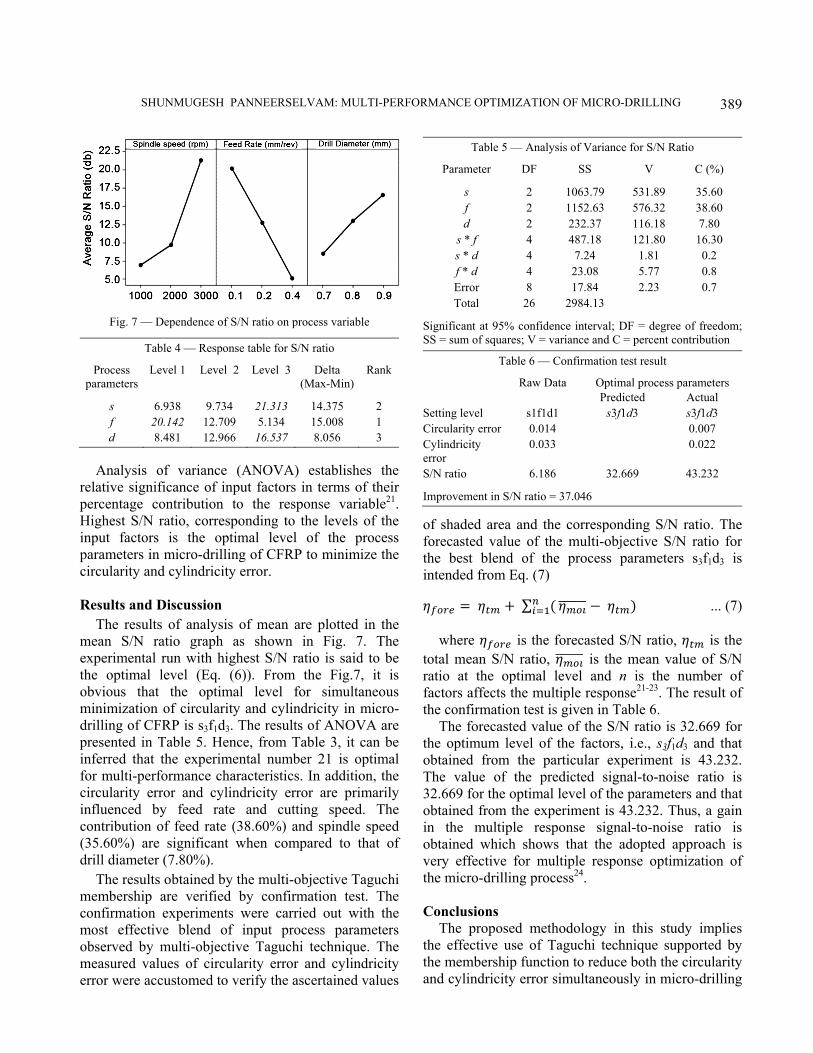
Fig. 7 — Dependence of S/N ratio on process variable
Table 4 — Response table for S/N ratio
Process parameters
Level 1 Level 2 Level 3 Delta (Max-Min)
Rank
s 6.938 9.734 21.313 14.375 2 f 20.142 12.709 5.134 15.008 1 d 8.481 12.966 16.537 8.056 3
Analysis of variance (ANOVA) establishes the
relative significance of input factors in terms of their percentage contribution to the response variable21. Highest S/N ratio, corresponding to the levels of the input factors is the optimal level of the process parameters in micro-drilling of CFRP to minimize the circularity and cylindricity error. Results and Discussion
The results of analysis of mean are plotted in the mean S/N ratio graph as shown in Fig. 7. The experimental run with highest S/N ratio is said to be the optimal level (Eq. (6)). From the Fig.7, it is obvious that the optimal level for simultaneous minimization of circularity and cylindricity in micro-drilling of CFRP is s3f1d3. The results of ANOVA are presented in Table 5. Hence, from Table 3, it can be inferred that the experimental number 21 is optimal for multi-performance characteristics. In addition, the circularity error and cylindricity error are primarily influenced by feed rate and cutting speed. The contribution of feed rate (38.60%) and spindle speed (35.60%) are significant when compared to that of drill diameter (7.80%).
The results obtained by the multi-objective Taguchi membership are verified by confirmation test. The confirmation experiments were carried out with the most effective blend of input process parameters observed by multi-objective Taguchi technique. The measured values of circularity error and cylindricity error were accustomed to verify the ascertained values
of shaded area and the corresponding S/N ratio. The forecasted value of the multi-objective S/N ratio for the best blend of the process parameters s3f1d3 is intended from Eq. (7)
𝜂 𝜂 ∑ 𝜂 𝜂 ... (7)
where 𝜂 is the forecasted S/N ratio, 𝜂 is the total mean S/N ratio, 𝜂 is the mean value of S/N ratio at the optimal level and n is the number of factors affects the multiple response21-23. The result of the confirmation test is given in Table 6.
The forecasted value of the S/N ratio is 32.669 for the optimum level of the factors, i.e., s3f1d3 and that obtained from the particular experiment is 43.232. The value of the predicted signal-to-noise ratio is 32.669 for the optimal level of the parameters and that obtained from the experiment is 43.232. Thus, a gain in the multiple response signal-to-noise ratio is obtained which shows that the adopted approach is very effective for multiple response optimization of the micro-drilling process24. Conclusions
The proposed methodology in this study implies the effective use of Taguchi technique supported by the membership function to reduce both the circularity and cylindricity error simultaneously in micro-drilling
Table 5 — Analysis of Variance for S/N Ratio
Parameter DF SS V C (%)
s 2 1063.79 531.89 35.60 f 2 1152.63 576.32 38.60 d 2 232.37 116.18 7.80
s * f 4 487.18 121.80 16.30 s * d 4 7.24 1.81 0.2 f * d 4 23.08 5.77 0.8 Error 8 17.84 2.23 0.7 Total 26 2984.13
Significant at 95% confidence interval; DF = degree of freedom;SS = sum of squares; V = variance and C = percent contribution
Table 6 — Confirmation test result
Raw Data Optimal process parameters Predicted Actual Setting level s1f1d1 s3f1d3 s3f1d3 Circularity error 0.014 0.007 Cylindricity error
0.033 0.022
S/N ratio 6.186 32.669 43.232
Improvement in S/N ratio = 37.046

INDIAN J. ENG. MATER. SCI., OCTOBER 2018
390
of CFRP. The current technique simplifies the standard related to the multi-objective improvement by employing a distinctive membership perform approach to convert the multiple responses into one response, that is then solved by victimisation Taguchi technique. The conclusions drawn from the experimental results are summarized as follows:
(i) Feed rate and spindle speed have a greater influence on circularity error and cylindricity error. In addition, lower feed rate and higher spindle speed minimizes the circularity and cylindricity errors.
(ii) The optimal parameter setting which simultaneously minimizes the circularity and cylindricity errors in micro-drilling of CFRP are spindle speed of 3000 rpm, feed rate of 0.1 mm/rev and drill diameter of 0.9 mm.
(iii) The membership function of every response is calculated in accordance with the experimental results, thereby eliminating the trivial task of assigning weights to responses.
(iv) The improvement of S/N ratio in confirmation test suggest that the Taguchi technique supported by membership function is appropriate for optimizing the parameters with multiple responses in drilling of CFRP within the range of parameters investigated.
(v) The effective use of the proposed system helps to optimize the process parameters with multiple responses in micro-drilling of CFRP, which will facilitate drilling of quality holes with minimum circularity and cylindricity errors.
References 1 Bhatnagar N, Ramakrishnan N, Naik N K & Komanduri R,
Int J Mach Tool Manuf, 35 (1995) 701-716. 2 Ferreira J R, Coppini N L & Miranda G W A, J Mater
Process Technol, 92 (1999) 135-140.
3 An Q, Ming W, Cai X & Chen M, Compos Struct, (2015). 4 Xu J, An Q & Chen M, Compos Struct, 117 (2014)
71-82. 5 Morioka K & Tomita Y, Mater Charact, 45 (2000)
125-136. 6 Abhishek K, Datta S & Mahapatra S S, Measurement, 77
(2016) 222-239. 7 Çelik A, Lazoglu I, Kara A & Kara F, J Mater Process
Technol, 223 (2015) 39-47. 8 Krishnamoorthy A, Boopathy S R, Palanikumar K &
Davim J P, Measurement, 45 (2012) 1286-1296. 9 Karpat Y, Bahtiyar O, Değer B & Kaftanoğlu B, CIRP Ann
Manuf Technol, 63 (2014) 81-84. 10 Eneyew E D & Ramulu M, J Mater Res Technol, 3 (2014)
354-362. 11 Abhishek K, Datta S & Mahapatra S S, Measurement, 77
(2016) 222-239. 12 Sadek A, Meshreki M & Attia M H, CIRP Ann Manuf
Technol, 61 (2012) 123-126. 13 Karpat Y, Değer B & Bahtiyar O, J Mater Process
Technol, 212 (2012) 2117-2127. 14 Ravisubramanian S & Shunmugam M S, Measurement, 73
(2015) 335-340. 15 Bhandari B, Hong Y S, Yoon H S, Moon J S, Pham M Q,
Lee G B & Ahn S H, Prec Eng, 38 (2014) 221-229. 16 Biermann D & Kirschner M, J Manuf Process, 20 (2015)
332-339. 17 Jeyapaul R, Shahabudeen P & Krishnaiah K, Int J Adv
Manuf Technol, 26 (2005) 1331-1337. 18 Gaitonde V N, Karnik S R, Achyutha B T &
Siddeswarappa B, J Mater Process Technol, 202 (2008) 374-379.
19 Heisel U & Pfeifroth T, Procedia CIRP, 1 (2012) 471-476. 20 Krishnaraj V, Prabukarthi A, Ramanathan A, Elanghovan
N, Kumar M S, Zitoune R & Davim J P, Compos Part B, 43 (2012) 1791-1799.
21 Taguchi G, Introduction to Quality Engineering, (Asian Productivity Organization, Tokyo), 1990.
22 Phadke M S, Quality Engineering using Robust Design, (Prentice Hall, Englewood Cliffs, New Jersey), 1989.
23 Ross P J, Taguchi Techniques for Quality Engineering, (McGraw-Hill, New York), 1996.
24 Pandey R K & Panda S S, Measurement, 59 (2015) 9-13.