Embed Size (px)
Citation preview
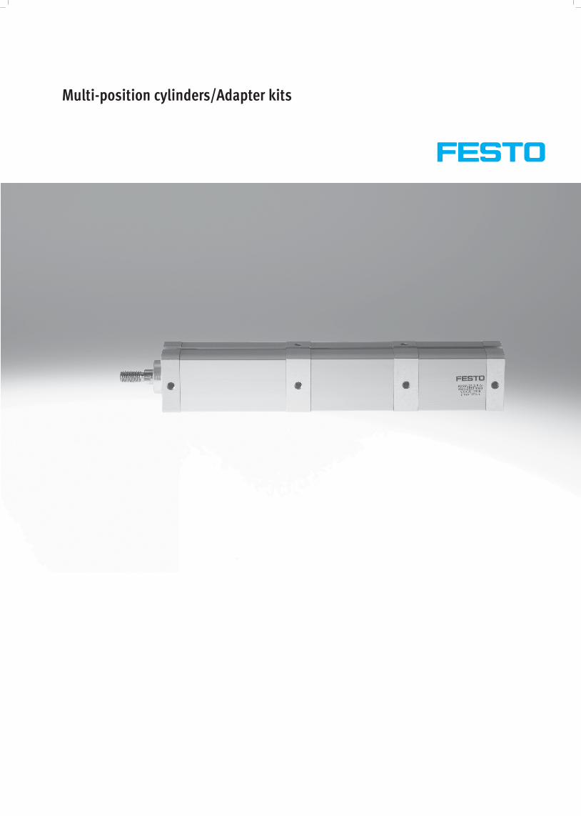
Multi-position cylinders/Adapter kits
Subject to change – 2010/022 � Internet: www.festo.com/catalogue/...
Multi-position cylinders ADNM, ADVUPProduct range overview
Function Design Type Piston∅ Stroke Pisto rod � Page/Internetg yp ∅
With female thread With male thread
g /
[mm] [mm]
Double- ADNM 25 1 … 1,000� �
4Double
acting
ADNM
Single-ended
25 1 … 1,000� �
4
acting Single ended
piston rod 40, 63, 100 1 … 2,000� �piston rod 40, 63, 100 1 … 2,000� �
ADVUP 25 1 … 1,000� �
28
Single-ended� �
g
piston rod 40, 63, 100 1 … 2,000� �
p� �
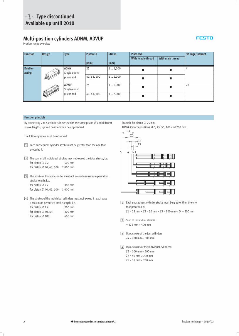
Function principle
By connecting 2 to 5 cylinders in series with the same piston ∅ and different
stroke lengths, up to 6 positions can be approached.
Example for piston ∅ 25mm:
ADNM-25 for 5 positions at 0, 25, 50, 100 and 200 mm.stroke lengths, up to 6 positions can be approached.
The following rules must be observed:
1 Each subsequent cylinder stroke must be greater than the one that
preceded it.
2 The sum of all individual strokes may not exceed the total stroke, i.e.
for piston ∅ 25: 500 mm
for piston ∅ 40, 63, 100: 2,000 mm
3 The stroke of the last cylinder must not exceed a maximum permitted
stroke length, i.e.
for piston ∅ 25: 300 mm
for piston ∅ 40, 63, 100: 1,000 mm
4 The strokes of the individual cylinders must not exceed in each case4 The strokes of the individual cylinders must not exceed in each case
a maximum permitted stroke length, i.e.
for piston ∅ 25: 200 mm
for piston ∅ 40, 63: 300 mm
for piston ∅ 100: 400 mm
1 Each subsequent cylinder stroke must be greater than the one
that preceded it:
Z1 = 25 mm < Z2 = 50 mm < Z3 = 100 mm < Z4 = 200 mm
2 Sum of individual strokes:
= 375 mm < 500 mm
3 Max. stroke of the last cylinder:
Z4 = 200 mm < 300 mm
4 Max. strokes of the individual cylinders:
Z3 = 100 mm < 200 mm
Z2 = 50 mm < 200 mm
Z1 = 25 mm < 200 mm
-U- Type discontinuedAvailable up until 2010

2010/02 – Subject to change 3� Internet: www.festo.com/catalogue/...
Adapter kits DPNC/DPNG/DPNA/DPVUProduct range overview
Design Type For cylinders Piston∅ Overall stroke length � Page/Internet
[mm] [mm]
DPNC DNCB, DNC, ADVC
ADN ∅125
ADVU ∅125
32, 40, 50, 63, 80, 100, 125 1,000 42
DPNG DNG 32, 40, 50, 63, 80, 100 1,000 42
DPNA ADN 12, 16, 20, 25, 32, 40, 50, 63, 80, 100 600 … 1,000 43
DPVU ADVU 12, 16, 20, 25, 32, 40, 50, 63, 80, 100 400 … 800 43
Function principle
A 3 or 4-position cylinder consists of
two separate cylinders whose piston
rods advance in opposing directions.
Depending upon actuation and stroke
pattern, this type of cylinder can
assume up to four positions. In each
case the cylinder is driven precisely
against a stop. If one end of the piston
rod is fixed, the cylinder barrel
executes the movement. The cylinder
must be connected with flexible line
connections.
Implementing 3 positions Implementing 4 positions
Two cylinders with identical stroke
length must be connected to this end.
Two cylinders with different stroke
lengths must be connected to this
end.
Subject to change – 2010/024 � Internet: www.festo.com/catalogue/...
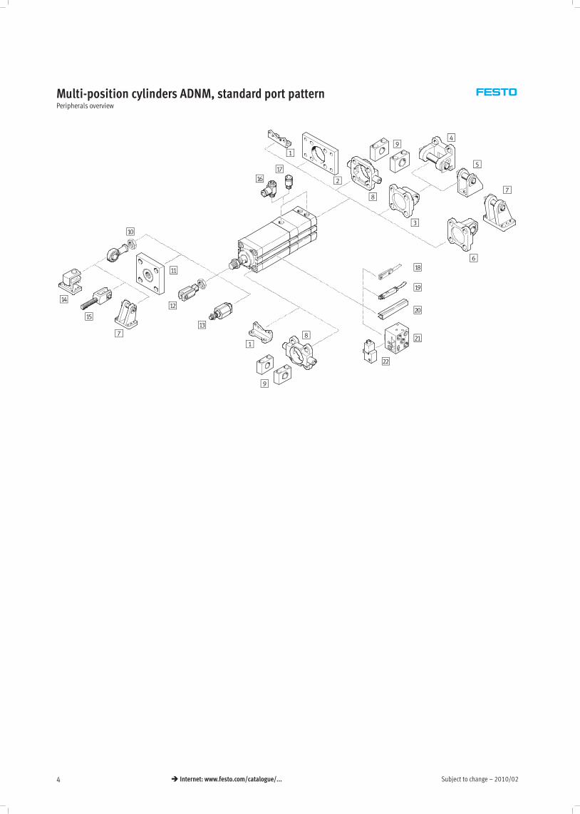
Multi-position cylinders ADNM, standard port patternPeripherals overview
1
2
3
4
5
6
7
8
9
aA
aB
aC
aD
aE
aFaG
aI
1
aH
bJ
aJ
7
8
9
bA
bB
2010/02 – Subject to change 5� Internet: www.festo.com/catalogue/...
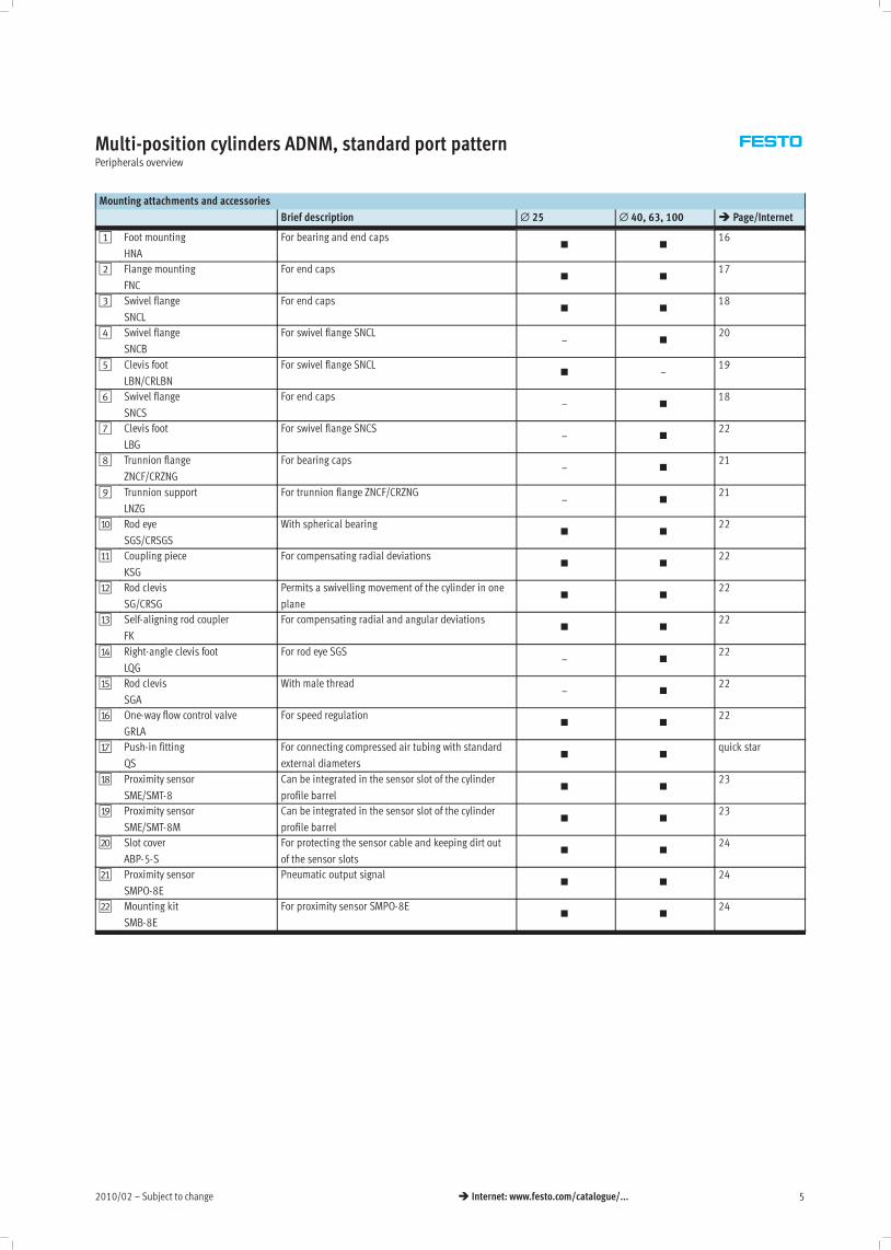
Multi-position cylinders ADNM, standard port patternPeripherals overview
Mounting attachments and accessories
Brief description ∅ 25 ∅ 40, 63, 100 � Page/Internet
1 Foot mounting
HNA
For bearing and end caps� �
16
2 Flange mounting
FNC
For end caps� �
17
3 Swivel flange
SNCL
For end caps� �
18
4 Swivel flange
SNCB
For swivel flange SNCL– �
20
5 Clevis foot
LBN/CRLBN
For swivel flange SNCL� –
19
6 Swivel flange
SNCS
For end caps– �
18
7 Clevis foot
LBG
For swivel flange SNCS– �
22
8 Trunnion flange
ZNCF/CRZNG
For bearing caps– �
21
9 Trunnion support
LNZG
For trunnion flange ZNCF/CRZNG– �
21
aJ Rod eye
SGS/CRSGS
With spherical bearing� �
22
aA Coupling piece
KSG
For compensating radial deviations� �
22
aB Rod clevis
SG/CRSG
Permits a swivelling movement of the cylinder in one
plane� �
22
aC Self-aligning rod coupler
FK
For compensating radial and angular deviations� �
22
aD Right-angle clevis foot
LQG
For rod eye SGS– �
22
aE Rod clevis
SGA
With male thread– �
22
aF One-way flow control valve
GRLA
For speed regulation� �
22
aG Push-in fitting
QS
For connecting compressed air tubing with standard
external diameters� �
quick star
aH Proximity sensor
SME/SMT-8
Can be integrated in the sensor slot of the cylinder
profile barrel� �
23
aI Proximity sensor
SME/SMT-8M
Can be integrated in the sensor slot of the cylinder
profile barrel� �
23
bJ Slot cover
ABP-5-S
For protecting the sensor cable and keeping dirt out
of the sensor slots� �
24
bA Proximity sensor
SMPO-8E
Pneumatic output signal� �
24
bB Mounting kit
SMB-8E
For proximity sensor SMPO-8E� �
24
Subject to change – 2010/026 � Internet: www.festo.com/catalogue/...
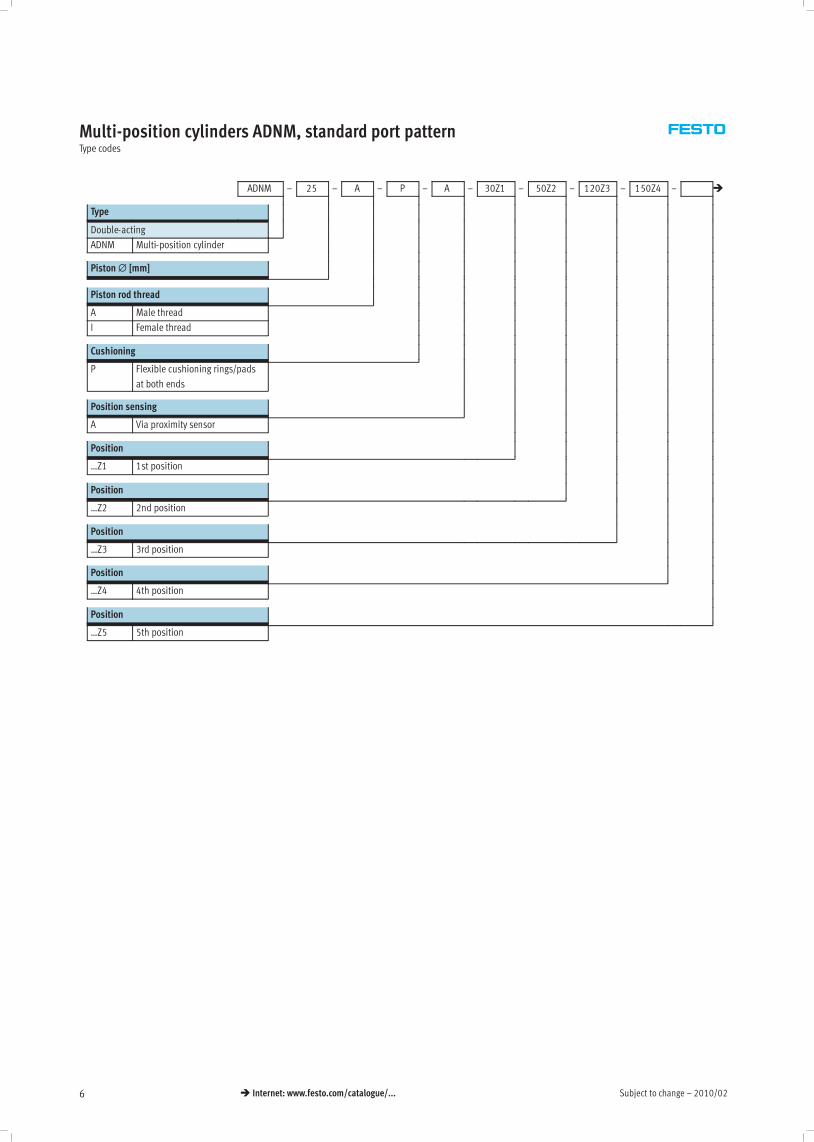
Multi-position cylinders ADNM, standard port patternType codes
ADNM – 25 – A – P – A – 30Z1 – 50Z2 – 120Z3 – 150Z4 – �
Type
Double-acting
ADNM Multi-position cylinder
Piston∅ [mm]
Piston rod thread
A Male thread
I Female thread
Cushioning
P Flexible cushioning rings/pads
at both ends
Position sensing
A Via proximity sensor
Position
…Z1 1st position
Position
…Z2 2nd position
Position
…Z3 3rd position
Position
…Z4 4th position
Position
…Z5 5th position

2010/02 – Subject to change 7� Internet: www.festo.com/catalogue/...
Multi-position cylinders ADNM, standard port patternType codes
� 20K2 – – 100K8 – S6 – TL
Male thread
…K2 Extended male piston rod
thread
Special thread
…K5 Special piston rod thread
Piston rod
…K8 Extended piston rod
Temperature resistance
S6 Heat-resistant seals up to
max. 120 °C
Captive rating plate
TL Laser etched rating plate
Subject to change – 2010/028 � Internet: www.festo.com/catalogue/...
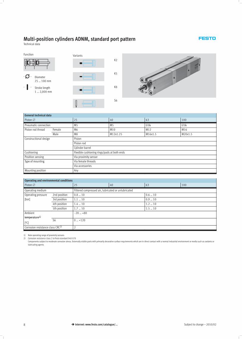
Multi-position cylinders ADNM, standard port patternTechnical data
Function
-N- Diameter
25 … 100 mm
-T- Stroke length
1 … 2,000 mm
Variants
K2
K5
K8
S6
General technical data
Piston ∅ 25 40 63 100
Pneumatic connection M5 M5 Gx Gx
Piston rod thread Female M6 M10 M12 M16
Male M8 M12x1.25 M16x1.5 M20x1.5
Constructional design Pistong
Piston rod
Cylinder barrel
Cushioning Flexible cushioning rings/pads at both ends
Position sensing Via proximity sensor
Type of mounting Via female threadsyp g
Via accessories
Mounting position Any
Operating and environmental conditions
Piston ∅ 25 40 63 100
Operating medium Filtered compressed air, lubricated or unlubricated
Operating pressure 2nd position 0.8 … 10 0.6 … 10p g p
[bar] 3rd position 1.1 … 10 0.9 … 10[ ]
4th position 1.4 … 10 1.2 … 10
5th position 1.7 … 10 1.5 … 10
Ambient
temperature1)–20 … +80
temperature1)
[°C]S6 0 … +120
Corrosion resistance class CRC2) 2
1) Note operating range of proximity sensors
2) Corrosion resistance class 2 to Festo standard 940 070
Components subject to moderate corrosion stress. Externally visible parts with primarily decorative surface requirements which are in direct contact with a normal industrial environment or media such as coolants or
lubricating agents

2010/02 – Subject to change 9� Internet: www.festo.com/catalogue/...
Multi-position cylinders ADNM, standard port patternTechnical data
Forces [N] and impact energy [J]
Piston ∅ 25 40 63 100
Theoretical force at 6 bar,
advancing
295 754 1870 4712
Theoretical force at 6 bar,
retracting
247 633 1681 4417
Max. impact energy at the 0.3 0.7 1.3 2.5p gy
end positions S6 0.15 0.35 0.65 1.25
Max. lateral force Fq as a function of the projection x
x [mm]
Fq[N]
∅ 25 mm
∅ 40 mm
∅ 63 mm
∅ 100 mm
Materials
Sectional view
132 2
4
Multi-position cylinder Basic version S6
1 Cylinder barrel Anodised aluminium Anodised aluminium
2 Cover Anodised aluminium Anodised aluminium
3 Piston rod High-alloy steel High-alloy steel
4 Flange screws Galvanised steel Galvanised steel
– Seals Polyurethane Fluoro elastomer

Subject to change – 2010/0210 � Internet: www.festo.com/catalogue/...
Multi-position cylinders ADNM, standard port patternTechnical data
Dimensions – Basic version Download CAD data� www.festo.com
∅ 25/Z2 – 2 cylinders
Cylinder 1Cylinder 2
1 Cylinder advancing
2 Cylinder retracting
Z1 = Stroke of cylinder 1
Z2 = Stroke of cylinder 2
∅ 40 … 100/Z2 – 2 cylinders
Cylinder 1Cylinder 2
1 Cylinder advancing
2 Cylinder retracting
Z1 = Stroke of cylinder 1
Z2 = Stroke of cylinder 2
Z3 – 3 cylinders
Cylinder 1Cylinder 2Cylinder 3
Z1 = Stroke of cylinder 1
Z2 = Stroke of cylinder 2
Z3 = Stroke of cylinder 3
Z4 – 4 cylinders
Cylinder 1Cylinder 2Cylinder 4 Cylinder 3
Z1 = Stroke of cylinder 1
Z2 = Stroke of cylinder 2
Z3 = Stroke of cylinder 3
Z4 = Stroke of cylinder 4

2010/02 – Subject to change 11� Internet: www.festo.com/catalogue/...
Multi-position cylinders ADNM, standard port patternTechnical data
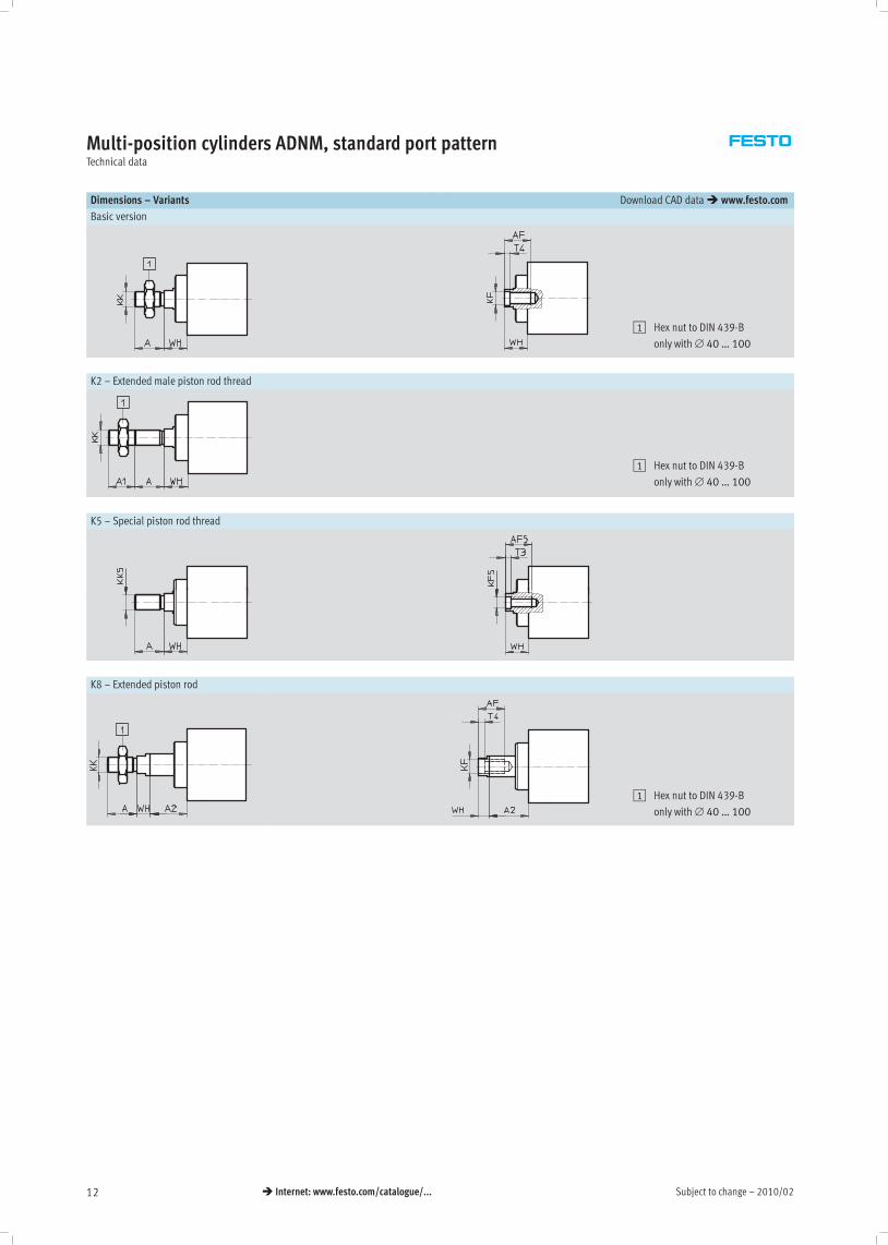
Dimensions – Variants Download CAD data� www.festo.com
Z5 – 5 cylinders
Cylinder 1Cylinder 3Cylinder 5 Cylinder 4 Cylinder 2
Z1 = Stroke of cylinder 1
Z2 = Stroke of cylinder 2
Z3 = Stroke of cylinder 3
Z4 = Stroke of cylinder 4
Z5 = Stroke of cylinder 5
∅ B
∅
BG D1
∅
E EE J3 LA MM
∅
[mm] f8 min. H9 +0.3 +0.2 h9
25 22 159
39.5M5
– 10
40 3516
954.5
M515
516
63 4216
1275.5
Gx23
520
100 55 1712
113.5Gx
40 25
∅ PL PL1 PL2 RT SF T2 TG VD
[mm] +0.2 +0.2 +0.2 +0.1 ±0.2
25 6 38.3 34.2 M5 92 1
26 6
408 2
40.4 39.5 M6 132.1
38 9.5
638.2
44 42 M8 172 6
56.5 12
100 10.5 51.2 52 M10 212.6
89 15.5
∅ ZA
Number of cylinders
ZB
Number of cylinders
[mm] 2 3 4 5 2 3 4 5
25 76.3 +1.2 110.5 +1.8 144.7 +2.4 178.9 +3 88.5 +1.6 122.7 +2.2 156.9 +2.8 191.1 +3.5
40 86.2 +1.2 125.5 +1.8 166.9 +2.4 209.9 +3 104.6 +1.6 143.9 +2.2 185.2 +2.8 228.2 +3.5
63 93.3 +1.2 135.7 +1.8 180.2 +2.4 226.3 +3 114.6 +1.6 157 +2.2 201.4 +2.8 247.5 +3.5
100 120.9 +1.2 172.8 +1.8 227 +2.4 282.8 +3 147.9 +1.6 199.8 +2.2 253.9 +2.8 309.7 +3.5
Stroke
Z5 ,
Absolute strokes
Relative strokesZ2 ,Z4 , Z3, Z1 ,
Subject to change – 2010/0212 � Internet: www.festo.com/catalogue/...
Multi-position cylinders ADNM, standard port patternTechnical data
Dimensions – Variants Download CAD data� www.festo.com
Basic version
1 Hex nut to DIN 439-B
only with ∅ 40 … 100
K2 – Extended male piston rod thread
1 Hex nut to DIN 439-B
only with ∅ 40 … 100
K5 – Special piston rod thread
K8 – Extended piston rod
1 Hex nut to DIN 439-B
only with ∅ 40 … 100
2010/02 – Subject to change 13� Internet: www.festo.com/catalogue/...
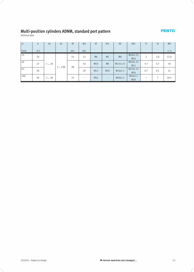
Multi-position cylinders ADNM, standard port patternTechnical data
∅ A A1 A2 AF AF5 KF KF5 KK KK5 T3 T4 WH
[mm] –0.5 min. min. +1.3
2516 14 12 M6 M5 M8
M10x1.25
M102 2.6 11.8
4022 1 … 20
1 150 20
16 M10 M8 M12x1.25M10x1.25
M123.3 4.7 18
6328
1 … 150 20
20 M12 M10 M16x1.5M12x1.25
M164.7 6.1 21
10040 1 … 30 25 – M16 – M20x1.5
M16x1.5
M20– 7 26.5
Subject to change – 2010/0214 � Internet: www.festo.com/catalogue/...
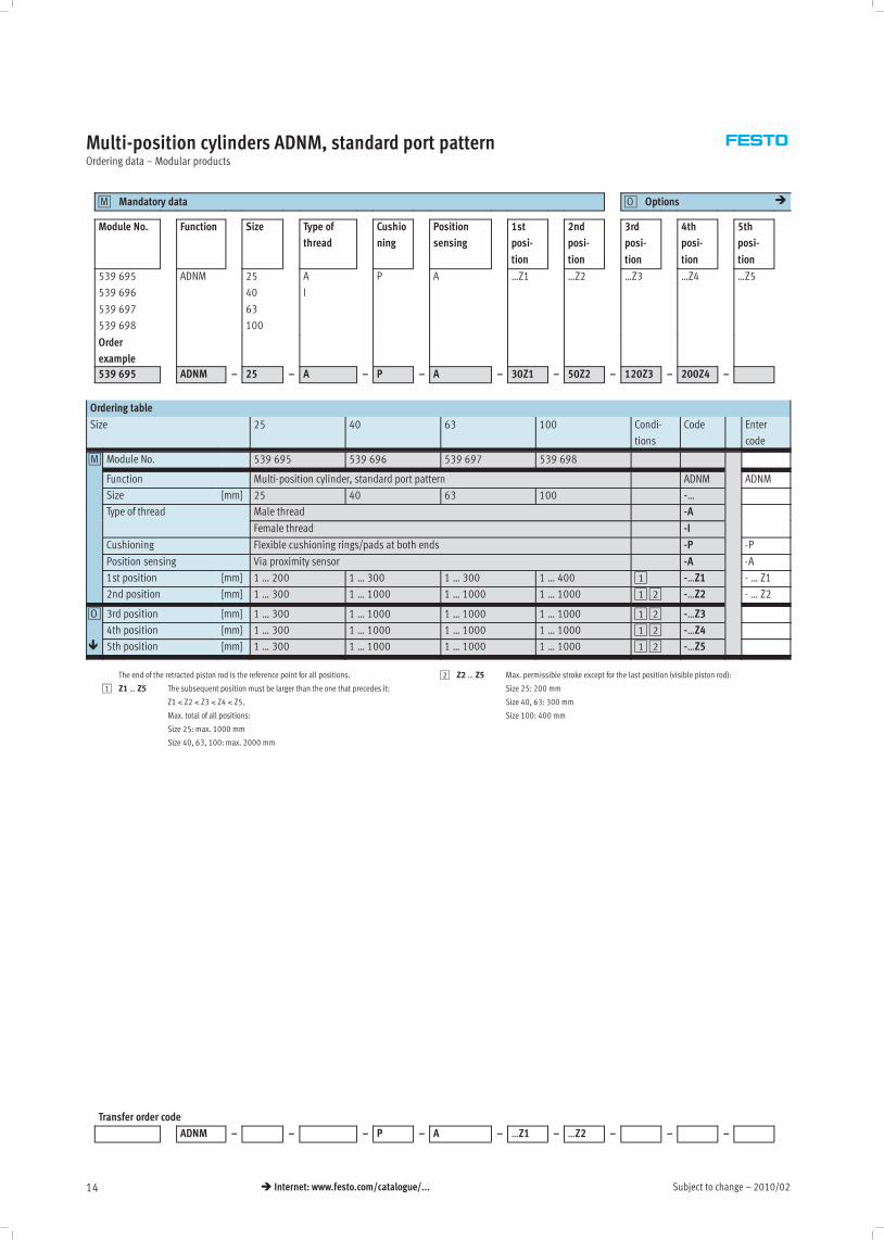
Multi-position cylinders ADNM, standard port patternOrdering data – Modular products
Mandatory data0M Options0O �
Module No. Function Size Type of
thread
Cushio
ning
Position
sensing
1st
posi-
tion
2nd
posi-
tion
3rd
posi-
tion
4th
posi-
tion
5th
posi-
tion
539 695
539 696
539 697
539 698
ADNM 25
40
63
100
A
I
P A …Z1 …Z2 …Z3 …Z4 …Z5
Order
example
539 695 ADNM – 25 – A – P – A – 30Z1 – 50Z2 – 120Z3 – 200Z4 –
Ordering table
Size 25 40 63 100 Condi-
tions
Code Enter
code
0M Module No. 539 695 539 696 539 697 539 698
Function Multi-position cylinder, standard port pattern ADNM ADNM
Size [mm] 25 40 63 100 -…
Type of thread Male thread -Ayp
Female thread -I
Cushioning Flexible cushioning rings/pads at both ends -P -P
Position sensing Via proximity sensor -A -A
1st position [mm] 1 … 200 1 … 300 1 … 300 1 … 400 1 -…Z1 - … Z1
2nd position [mm] 1 … 300 1 … 1000 1 … 1000 1 … 1000 12 -…Z2 - … Z2
0O 3rd position [mm] 1 … 300 1 … 1000 1 … 1000 1 … 1000 12 -…Z3
4th position [mm] 1 … 300 1 … 1000 1 … 1000 1 … 1000 12 -…Z4
� 5th position [mm] 1 … 300 1 … 1000 1 … 1000 1 … 1000 12 -…Z5
The end of the retracted piston rod is the reference point for all positions.
1 Z1 … Z5 The subsequent position must be larger than the one that precedes it:
Z1 < Z2 < Z3 < Z4 < Z5.
Max. total of all positions:
Size 25: max. 1000 mm
Size 40, 63, 100: max. 2000 mm
2 Z2 … Z5 Max. permissible stroke except for the last position (visible piston rod):
Size 25: 200 mm
Size 40, 63: 300 mm
Size 100: 400 mm
Transfer order code
ADNM – – – P – A – …Z1 – …Z2 – – –
2010/02 – Subject to change 15� Internet: www.festo.com/catalogue/...
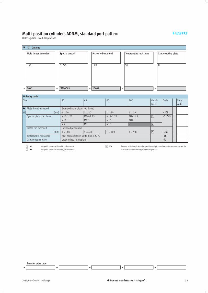
Multi-position cylinders ADNM, standard port patternOrdering data – Modular products
� Options0O
Male thread extended Special thread Piston rod extended Temperature resistance Captive rating plate
…K2 “…”K5 …K8 S6 TL
– 20K2 – “M10”K5 – 100K8 – –
Ordering table
Size 25 40 63 100 Condi-
tions
Code Enter
code
� Male thread extended Extended male piston rod thread
0O [mm] 1 … 20 1 … 20 1 … 20 1 … 30 -…K2
Special piston rod thread M10x1.25 M10x1.25 M12x1.25 M16x1.5 3 -“…”K5p p
M10 M12 M16 M20
M5 M8 M10 – 4
Piston rod extended Extended piston rod
[mm] 1 … 300 1 … 400 1 … 400 1 … 500 5 -…K8
Temperature resistance Heat-resistant seals up to max. 120 °C -S6
Captive rating plate Laser etched rating plate -TL
3 K5 Only with piston rod thread A (male thread)
4 K5 Only with piston rod thread I (female thread)
5 K8 The sum of the length of the last position and piston rod extension must not exceed the
maximum permissible length of the last position
Transfer order code
– – – – –
Subject to change – 2010/0216 � Internet: www.festo.com/catalogue/...
Multi-position cylinders ADNM, standard port patternAccessories
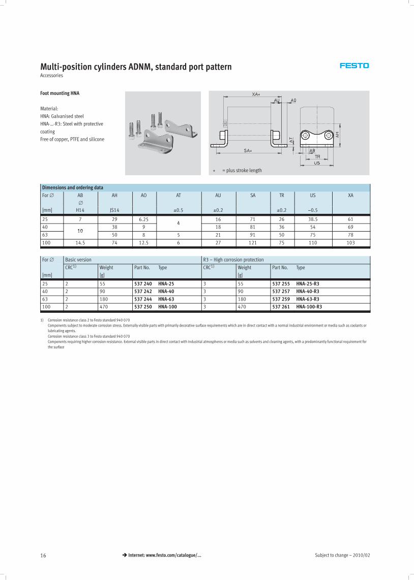
Foot mounting HNA
Material:
HNA: Galvanised steel
HNA-…-R3: Steel with protective
coating
Free of copper, PTFE and silicone
+ = plus stroke length
Dimensions and ordering data
For ∅ AB
∅
AH AO AT AU SA TR US XA
[mm] H14 JS14 ±0.5 ±0.2 ±0.2 −0.5
25 7 29 6.254
16 71 26 38.5 61
4010
38 94
18 81 36 54 69
6310
50 8 5 21 91 50 75 78
100 14.5 74 12.5 6 27 121 75 110 103
For ∅ Basic version R3 – High corrosion protection
[mm]
CRC1) Weight
[g]
Part No. Type CRC1) Weight
[g]
Part No. Type
25 2 55 537 240 HNA-25 3 55 537 255 HNA-25-R3
40 2 90 537 242 HNA-40 3 90 537 257 HNA-40-R3
63 2 180 537 244 HNA-63 3 180 537 259 HNA-63-R3
100 2 470 537 250 HNA-100 3 470 537 261 HNA-100-R3
1) Corrosion resistance class 2 to Festo standard 940 070
Components subject to moderate corrosion stress. Externally visible parts with primarily decorative surface requirements which are in direct contact with a normal industrial environment or media such as coolants or
lubricating agents.
Corrosion resistance class 3 to Festo standard 940 070
Components requiring higher corrosion resistance. External visible parts in direct contact with industrial atmospheres or media such as solvents and cleaning agents, with a predominantly functional requirement for
the surface
2010/02 – Subject to change 17� Internet: www.festo.com/catalogue/...
Multi-position cylinders ADNM, standard port patternAccessories
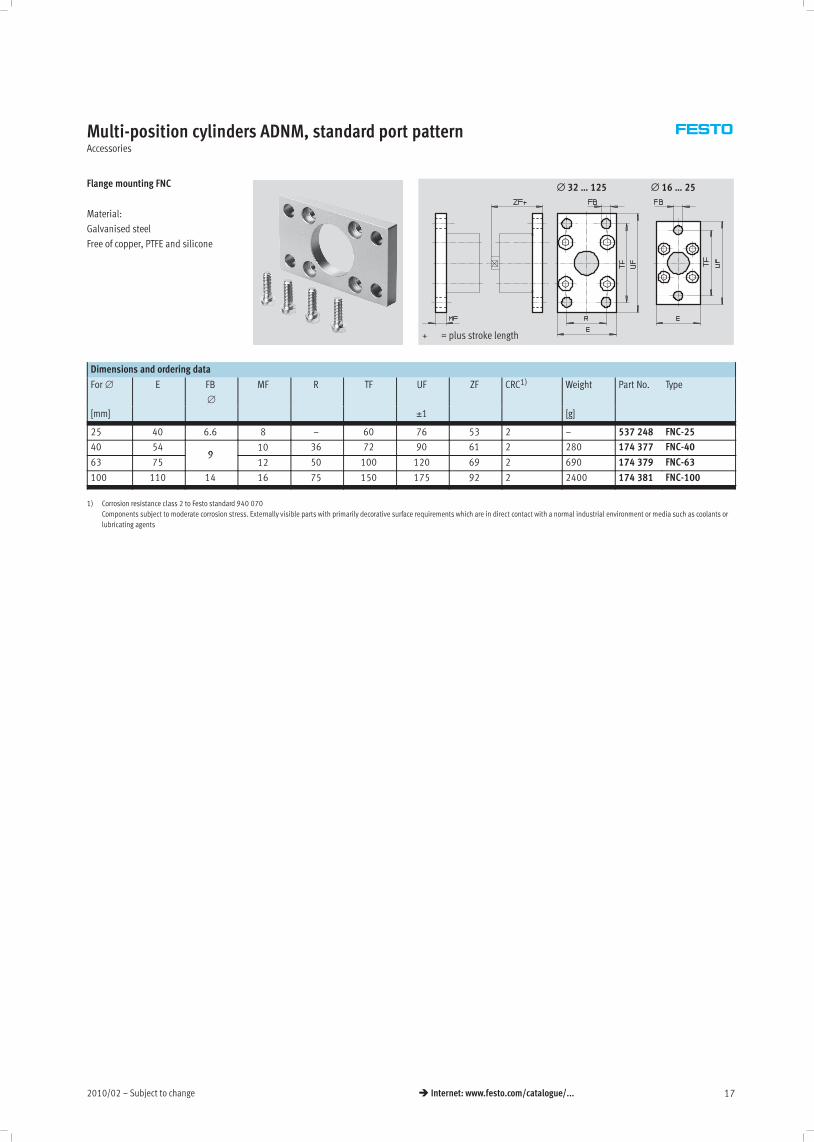
Flange mounting FNC
Material:
Galvanised steel
Free of copper, PTFE and silicone
+ = plus stroke length
∅ 32 … 125 ∅ 16 … 25
Dimensions and ordering data
For ∅ E FB
∅
MF R TF UF ZF CRC1) Weight Part No. Type
[mm] ±1 [g]
25 40 6.6 8 – 60 76 53 2 – 537 248 FNC-25
40 549
10 36 72 90 61 2 280 174 377 FNC-40
63 759
12 50 100 120 69 2 690 174 379 FNC-63
100 110 14 16 75 150 175 92 2 2400 174 381 FNC-100
1) Corrosion resistance class 2 to Festo standard 940 070
Components subject to moderate corrosion stress. Externally visible parts with primarily decorative surface requirements which are in direct contact with a normal industrial environment or media such as coolants or
lubricating agents

Subject to change – 2010/0218 � Internet: www.festo.com/catalogue/...
Multi-position cylinders ADNM, standard port patternAccessories
Swivel flange SNCL
Material:
SNCL: Die-cast aluminium
SNCL-…-R3: Die-cast aluminium with
protective coating
Free of copper, PTFE and silicone
+ = plus stroke length
Dimensions and ordering data
For ∅ CD
∅
EW FL L MR XC
[mm] H9 ±0.2
25 8 16h12 20 14 8 65
40 12 28–0.2/–0.6 25 16 12 76
63 16 40–0.2/–0.6 32 21 16 89
100 20 60–0.2/–0.6 41 27 20 117
For ∅ Basic version R3 – High corrosion protection
[mm]
CRC1) Weight
[g]
Part No. Type CRC1) Weight
[g]
Part No. Type
25 2 45 537 793 SNCL-25 3 45 537 797 SNCL-25-R3
40 2 115 174 405 SNCL-40 – – –
63 2 270 174 407 SNCL-63 – – –
100 2 700 174 409 SNCL-100 – – –
1) Corrosion resistance class 2 to Festo standard 940 070
Components subject to moderate corrosion stress. Externally visible parts with primarily decorative surface requirements which are in direct contact with a normal industrial environment or media such as coolants or
lubricating agents.
Corrosion resistance class 3 to Festo standard 940 070
Components requiring higher corrosion resistance. External visible parts in direct contact with industrial atmospheres or media such as solvents and cleaning agents, with a predominantly functional requirement for
the surface
Swivel flange SNCS
Material:
Die-cast aluminium
+ = plus stroke length
Dimensions and ordering data
For ∅ CN
∅
EP EX FL LT MS XC CRC1) Weight Part No. Type
[mm] H7 ±0.2 ±0.2 [g]
40 12 12 16 25 16 17 70 2 125 174 398 SNCS-40
63 16 15 21 32 21 22 81 2 280 174 400 SNCS-63
100 20 18 25 41 27 29 108 2 700 174 402 SNCS-100
1) Corrosion resistance class 2 to Festo standard 940 070
Components subject to moderate corrosion stress. Externally visible parts with primarily decorative surface requirements which are in direct contact with a normal industrial environment or media such as coolants or
lubricating agents
2010/02 – Subject to change 19� Internet: www.festo.com/catalogue/...
Multi-position cylinders ADNM, standard port patternAccessories
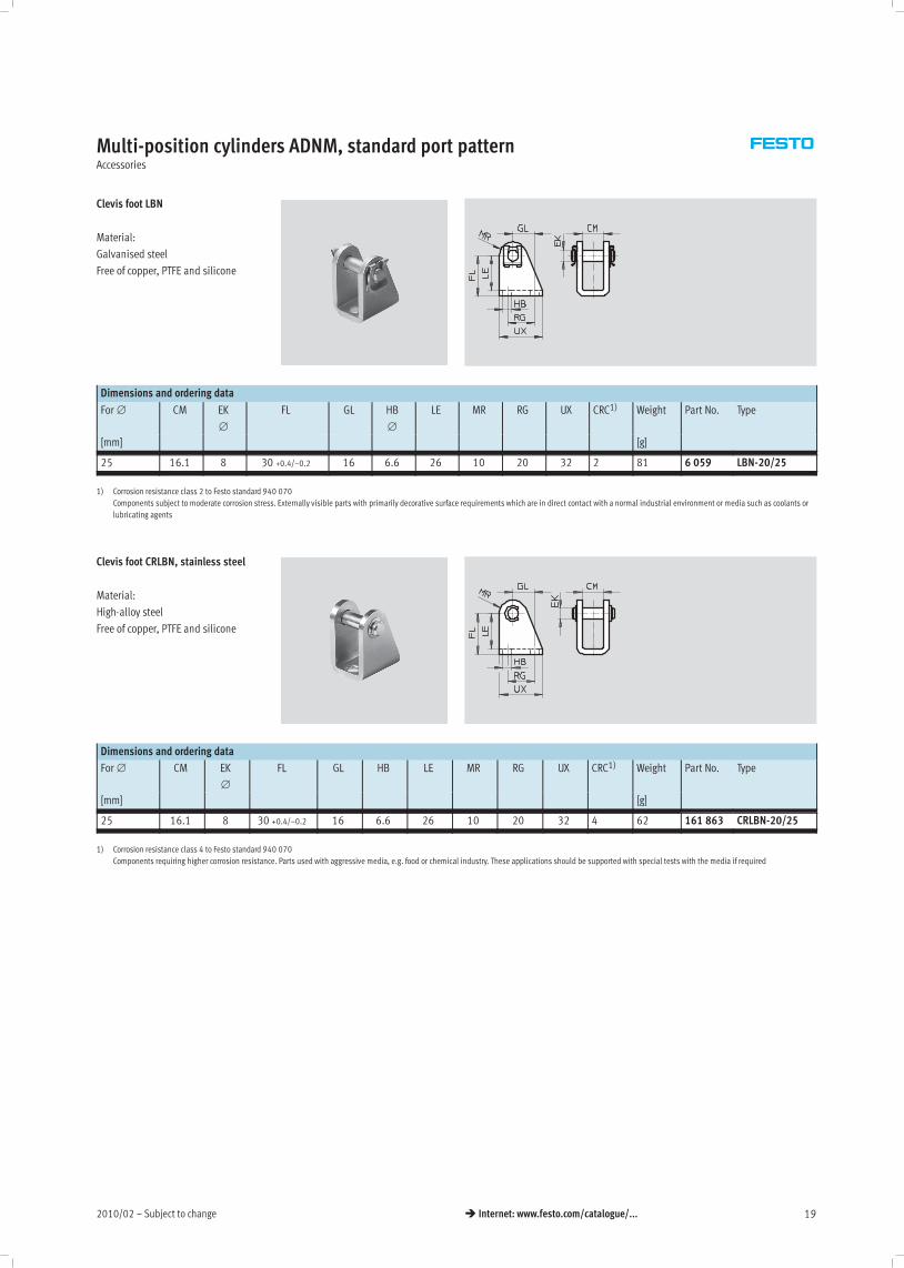
Clevis foot LBN
Material:
Galvanised steel
Free of copper, PTFE and silicone
Dimensions and ordering data
For ∅ CM EK
∅
FL GL HB
∅
LE MR RG UX CRC1) Weight Part No. Type
[mm] [g]
25 16.1 8 30 +0.4/–0.2 16 6.6 26 10 20 32 2 81 6 059 LBN-20/25
1) Corrosion resistance class 2 to Festo standard 940 070
Components subject to moderate corrosion stress. Externally visible parts with primarily decorative surface requirements which are in direct contact with a normal industrial environment or media such as coolants or
lubricating agents
Clevis foot CRLBN, stainless steel
Material:
High-alloy steel
Free of copper, PTFE and silicone
Dimensions and ordering data
For ∅ CM EK
∅
FL GL HB LE MR RG UX CRC1) Weight Part No. Type
[mm] [g]
25 16.1 8 30 +0.4/–0.2 16 6.6 26 10 20 32 4 62 161 863 CRLBN-20/25
1) Corrosion resistance class 4 to Festo standard 940 070
Components requiring higher corrosion resistance. Parts used with aggressive media, e.g. food or chemical industry. These applications should be supported with special tests with the media if required

Subject to change – 2010/0220 � Internet: www.festo.com/catalogue/...
Multi-position cylinders ADNM, standard port patternAccessories
Swivel flange
SNCB/SNCB-…-R3
Material:
SNCB: Die-cast aluminium
SNCB-…-R3: Die-cast aluminium with
protective coating, high corrosion
protection
Free of copper, PTFE and silicone
+ = plus stroke length
Dimensions and ordering data
For ∅ CB EK
∅
FL L MR UB XC
[mm] H14 e8 ±0.2 h14
40 28 12 25 16 12 52 76
63 40 16 32 21 16 70 89
100 60 20 41 27 20 110 117
For ∅ Basic version R3 – High corrosion protection
[mm]
CRC1) Weight
[g]
Part No. Type CRC1) Weight
[g]
Part No. Type
40 2 150 174 391 SNCB-40 3 150 176 945 SNCB-40-R3
63 2 365 174 393 SNCB-63 3 365 176 947 SNCB-63-R3
100 2 925 174 395 SNCB-100 3 925 176 949 SNCB-100-R3
1) Corrosion resistance class 2 to Festo standard 940 070
Components subject to moderate corrosion stress. Externally visible parts with primarily decorative surface requirements which are in direct contact with a normal industrial environment or media such as coolants or
lubricating agents.
Corrosion resistance class 3 to Festo standard 940 070
Components requiring higher corrosion resistance. External visible parts in direct contact with industrial atmospheres or media such as solvents and cleaning agents, with a predominantly functional requirement for
the surface
2010/02 – Subject to change 21� Internet: www.festo.com/catalogue/...
Multi-position cylinders ADNM, standard port patternAccessories
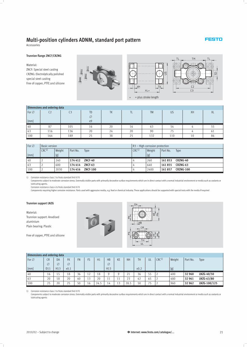
Trunnion flange ZNCF/CRZNG
Material:
ZNCF: Special steel casting
CRZNG: Electrolytically polished
special steel casting
Free of copper, PTFE and silicone
+ = plus stroke length
Dimensions and ordering data
For ∅ C2 C3 TD
∅
TK TL TM US XH XL
[mm] e9
40 87 105 16 20 16 63 54 4 55
63 116 136 20 24 20 90 75 4 61
100 164 189 25 38 25 132 110 10 86
For ∅ Basic version R3 – High corrosion protection
[mm]
CRC1) Weight
[g]
Part No. Type CRC1) Weight
[g]
Part No. Type
40 2 240 174 412 ZNCF-40 4 260 161 853 CRZNG-40
63 2 600 174 414 ZNCF-63 4 640 161 855 CRZNG-63
100 2 2030 174 416 ZNCF-100 4 2400 161 857 CRZNG-100
1) Corrosion resistance class 2 to Festo standard 940 070
Components subject to moderate corrosion stress. Externally visible parts with primarily decorative surface requirements which are in direct contact with a normal industrial environment or media such as coolants or
lubricating agents.
Corrosion resistance class 4 to Festo standard 940 070
Components requiring higher corrosion resistance. Parts used with aggressive media, e.g. food or chemical industry. These applications should be supported with special tests with the media if required
Trunnion support LNZG
Material:
Trunnion support: Anodised
aluminium
Plain bearing: Plastic
Free of copper, PTFE and silicone
Dimensions and ordering data
For ∅ CR
∅
DA
∅
FK
∅
FN FS H1 HB
∅
KE NH TH UL CRC1) Weight Part No. Type
[mm] D11 H13 ±0.1 H13 ±0.2 [g]
40 16 15 18 36 12 18 9 9 21 36 55 2 400 32 960 LNZG-40/50
63 20 18 20 40 13 20 11 11 23 42 65 2 480 32 961 LNZG-63/80
100 25 20 25 50 16 24.5 14 13 28.5 50 75 2 960 32 962 LNZG-100/125
1) Corrosion resistance class 2 to Festo standard 940 070
Components subject to moderate corrosion stress. Externally visible parts with primarily decorative surface requirements which are in direct contact with a normal industrial environment or media such as coolants or
lubricating agents

Subject to change – 2010/0222 � Internet: www.festo.com/catalogue/...
Multi-position cylinders ADNM, standard port patternAccessories
Ordering data – Piston rod attachments Technical data� Internet: piston rod attachment
Designation For ∅ Part No. Type Designation For ∅ Part No. Type
Rod eye SGS Rod clevis SGA for rod eye SGS
25 9 255 SGS-M8 25 –
40 9 262 SGS-M12x1,25 40 10 767 SGA-M12x1,25
63 9 263 SGS-M16x1,5 63 10 768 SGA-M16x1,5
100 9 264 SGS-M20x1,5 100 10 769 SGA-M20x1,5
Rod clevis SG Self-aligning rod coupler FK
25 3 111 SG-M8 25 2 062 FK-M8
40 6 145 SG-M12x1,25 40 6 141 FK-M12x1,25
63 6 146 SG-M16x1,5 63 6 142 FK-M16x1,5
100 6 147 SG-M20x1,5 100 6 143 FK-M20x1,5
Coupling piece KSG
25 –
40 32 964 KSG-M12x1,25
63 32 965 KSG-M16x1,5
100 32 966 KSG-M20x1,5
Ordering data – Corrosion and acid resistant piston rod attachments Technical data� Internet: piston rod attachment
Designation For ∅ Part No. Type Designation For ∅ Part No. Type
Rod eye CRSGS Rod clevis CRSG
25 195 581 CRSGS-M8 25 13 568 CRSG-M8
40 195 583 CRSGS-M12x1,25 40 13 570 CRSG-M12x1,25
63 195 584 CRSGS-M16x1,5 63 13 571 CRSG-M16x1,5
100 195 585 CRSGS-M20x1,5 100 13 572 CRSG-M20x1,5
-H- Note
Piston rod attachments for cylinders
with special thread (variant K5)
� www.festo.com
Ordering data – Mounting attachments Technical data� Internet: mounting attachment
Designation For ∅ Part No. Type Designation For ∅ Part No. Type
Clevis foot LBG for rod eye SGS Right-angle clevis foot LQG for rod eye SGS
25 – 25 –
40 31 762 LBG-40 40 31 769 LQG-40
63 31 764 LBG-63 63 31 771 LQG-63
100 31 766 LBG-100 100 31 773 LQG-100
Ordering data – One-way flow control valves Technical data� Internet: grla
Connection Material Part No. Type
For ∅ For tubing O.D.
yp
For exhaust air
25, 40 3 Metal design 193 137 GRLA-M5-QS-3-D5,
4
g
193 138 GRLA-M5-QS-4-D
63, 100 4 193 143 GRLA-x-QS-4-D3,
6 193 144 GRLA-x-QS-6-D
8 193 145 GRLA-x-QS-8-D
2010/02 – Subject to change 23� Internet: www.festo.com/catalogue/...
Multi-position cylinders ADNM, standard port patternAccessories
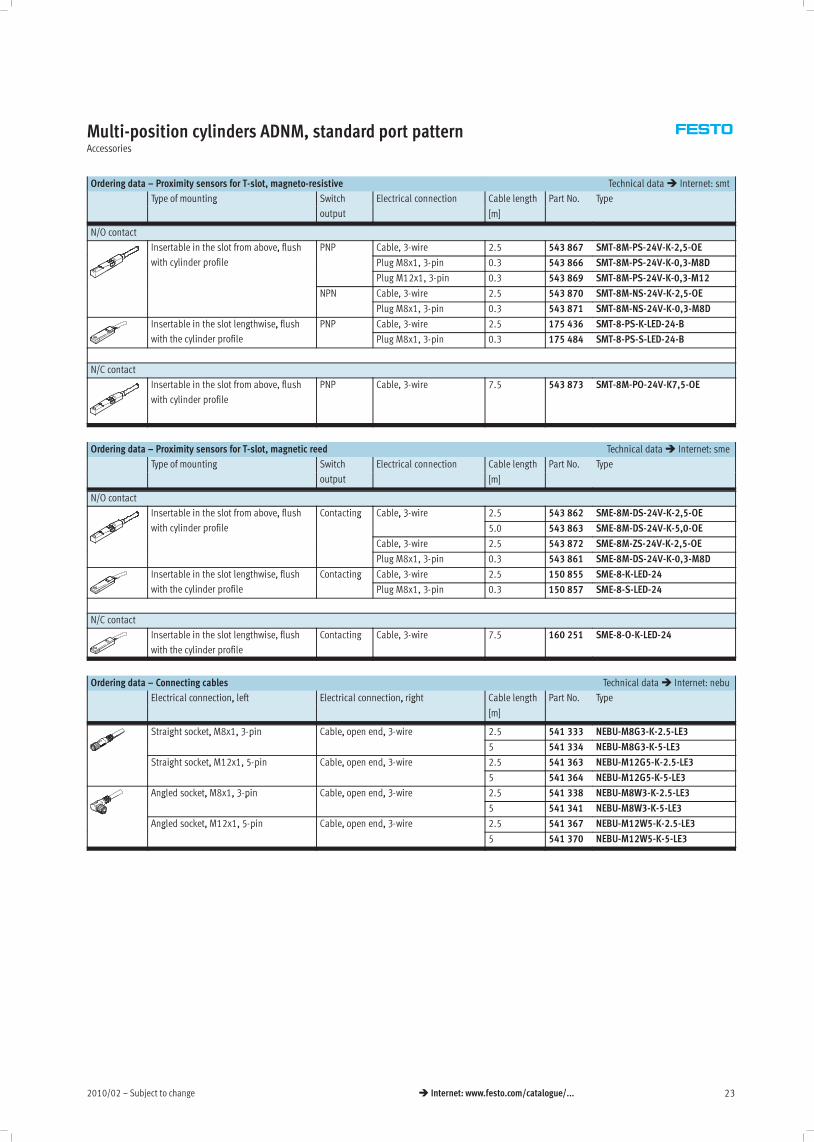
Ordering data – Proximity sensors for T-slot, magneto-resistive Technical data� Internet: smt
Type of mounting Switch Electrical connection Cable length Part No. Typeyp g
output [m]
yp
N/O contact
Insertable in the slot from above, flush PNP Cable, 3-wire 2.5 543 867 SMT-8M-PS-24V-K-2,5-OE,
with cylinder profile Plug M8x1, 3-pin 0.3 543 866 SMT-8M-PS-24V-K-0,3-M8Dy p
Plug M12x1, 3-pin 0.3 543 869 SMT-8M-PS-24V-K-0,3-M12
NPN Cable, 3-wire 2.5 543 870 SMT-8M-NS-24V-K-2,5-OE
Plug M8x1, 3-pin 0.3 543 871 SMT-8M-NS-24V-K-0,3-M8D
Insertable in the slot lengthwise, flush PNP Cable, 3-wire 2.5 175 436 SMT-8-PS-K-LED-24-Bg ,
with the cylinder profile Plug M8x1, 3-pin 0.3 175 484 SMT-8-PS-S-LED-24-B
N/C contact
Insertable in the slot from above, flush
with cylinder profile
PNP Cable, 3-wire 7.5 543 873 SMT-8M-PO-24V-K7,5-OE
Ordering data – Proximity sensors for T-slot, magnetic reed Technical data� Internet: sme
Type of mounting Switch Electrical connection Cable length Part No. Typeyp g
output [m]
yp
N/O contact
Insertable in the slot from above, flush Contacting Cable, 3-wire 2.5 543 862 SME-8M-DS-24V-K-2,5-OE,
with cylinder profile
g , 3
5.0 543 863 SME-8M-DS-24V-K-5,0-OEy p
Cable, 3-wire 2.5 543 872 SME-8M-ZS-24V-K-2,5-OE
Plug M8x1, 3-pin 0.3 543 861 SME-8M-DS-24V-K-0,3-M8D
Insertable in the slot lengthwise, flush Contacting Cable, 3-wire 2.5 150 855 SME-8-K-LED-24g ,
with the cylinder profile
g
Plug M8x1, 3-pin 0.3 150 857 SME-8-S-LED-24
N/C contact
Insertable in the slot lengthwise, flush
with the cylinder profile
Contacting Cable, 3-wire 7.5 160 251 SME-8-O-K-LED-24
Ordering data – Connecting cables Technical data� Internet: nebu
Electrical connection, left Electrical connection, right Cable length Part No. Type, , g
[m]
yp
Straight socket, M8x1, 3-pin Cable, open end, 3-wire 2.5 541 333 NEBU-M8G3-K-2.5-LE3g , , 3 p , p , 3
5 541 334 NEBU-M8G3-K-5-LE3
Straight socket, M12x1, 5-pin Cable, open end, 3-wire 2.5 541 363 NEBU-M12G5-K-2.5-LE3g , , 5 p , p , 3
5 541 364 NEBU-M12G5-K-5-LE3
Angled socket, M8x1, 3-pin Cable, open end, 3-wire 2.5 541 338 NEBU-M8W3-K-2.5-LE3g , , 3 p , p , 3
5 541 341 NEBU-M8W3-K-5-LE3
Angled socket, M12x1, 5-pin Cable, open end, 3-wire 2.5 541 367 NEBU-M12W5-K-2.5-LE3g , , 5 p , p , 3
5 541 370 NEBU-M12W5-K-5-LE3

Subject to change – 2010/0224 � Internet: www.festo.com/catalogue/...
Multi-position cylinders ADNM, standard port patternAccessories
Ordering data – Rectangular proximity sensors, pneumatic Technical data� Internet: smpo
Pneumatic connection Part No. Type
3/2-way valve, normally closed
Female thread M5 178 563 SMPO-8E
Ordering data – Mounting kit for proximity sensors SMPO-8E Technical data� Internet: smb
Assembly Part No. Type
Clamped in T-slot 178 230 SMB-8E
Ordering data – Slot cover for T-slot
Assembly Length Part No. Type
Insertable from
above
2x 0.5 m 151 680 ABP-5-S
2010/02 – Subject to change 25� Internet: www.festo.com/catalogue/...
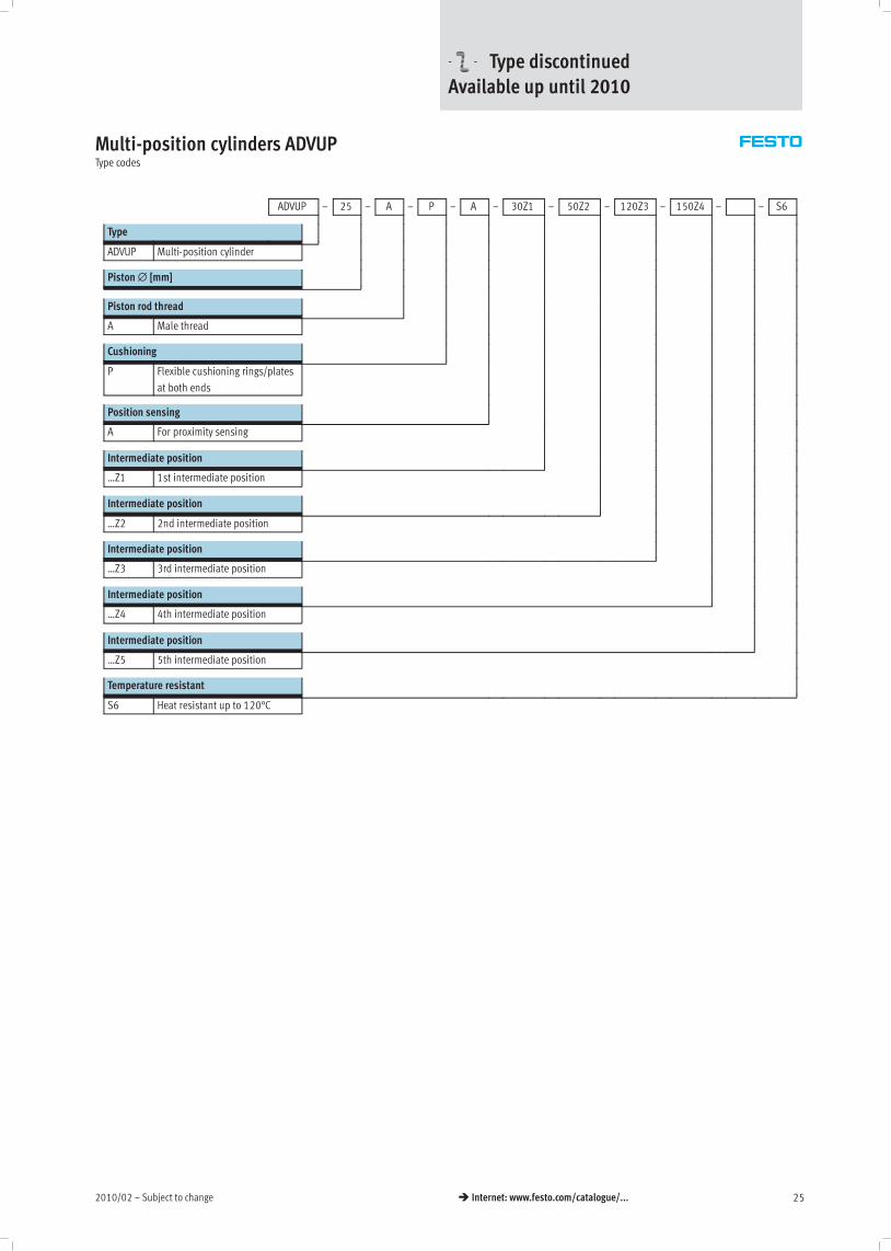
Multi-position cylinders ADVUPType codes
ADVUP – 25 – A – P – A – 30Z1 – 50Z2 – 120Z3 – 150Z4 – – S6
Type
ADVUP Multi-position cylinder
Piston∅ [mm]
Piston rod thread
A Male thread
Cushioning
P Flexible cushioning rings/plates
at both ends
Position sensing
A For proximity sensing
Intermediate position
…Z1 1st intermediate position
Intermediate position
…Z2 2nd intermediate position
Intermediate position
…Z3 3rd intermediate position
Intermediate position
…Z4 4th intermediate position
Intermediate position
…Z5 5th intermediate position
Temperature resistant
S6 Heat resistant up to 120°C
-U- Type discontinuedAvailable up until 2010
Subject to change – 2010/0226 � Internet: www.festo.com/catalogue/...
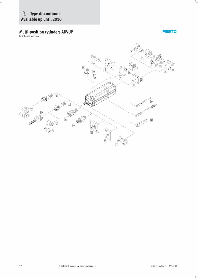
Multi-position cylinders ADVUPPeripherals overview
1
1
2
3
4
5
6
7
8
9
aJ
aJ
aAaB
aC
aD
aE
aF
aG
aH
aI
bJ
bA
-U- Type discontinuedAvailable up until 2010
2010/02 – Subject to change 27� Internet: www.festo.com/catalogue/...
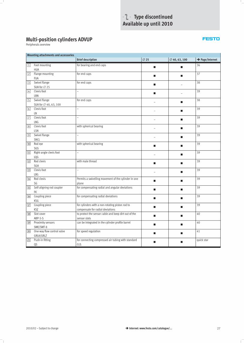
Multi-position cylinders ADVUPPeripherals overview
Mounting attachments and accessories
Brief description ∅ 25 ∅ 40, 63, 100 � Page/Internet
1 Foot mounting
HUA
for bearing and end caps� �
36
2 Flange mounting
FUA
for end caps� �
37
3 Swivel flange
SUA for ∅ 25
for end caps� –
38
4 Clevis foot
LBN
–� –
39
5 Swivel flange
SUA for ∅ 40, 63, 100
for end caps– �
38
6 Clevis foot
LN
–– �
39
7 Clevis foot
LNG
–– �
39
8 Clevis foot
LSN
with spherical bearing– �
39
9 Swivel flange
SNCL
–– �
39
aJ Rod eye
SGS
with spherical bearing� �
39
aA Right-angle clevis foot
LQG
–– �
39
aB Rod clevis
SGA
with male thread� �
39
aC Clevis foot
LBG
–– �
39
aD Rod clevis
SG
Permits a swivelling movement of the cylinder in one
plane� �
39
aE Self-aligning rod coupler
FK
for compensating radial and angular deviations� �
39
aF Coupling piece
KSG
for compensating radial deviations� �
39
aG Coupling piece
KSZ
for cylinders with a non-rotating piston rod to
compensate for radial deviations� �
39
aH Slot cover
ABP-5-S
to protect the sensor cable and keep dirt out of the
sensor slots� �
40
aI Proximity sensors
SME/SMT-8
can be integrated in the cylinder profile barrel� �
40
bJ One-way flow control valve
GRLA/GRLZ
for speed regulation� �
41
bA Push-in fitting
QS
for connecting compressed air tubing with standard
O.D.� �
quick star
-U- Type discontinuedAvailable up until 2010
Subject to change – 2010/0228 � Internet: www.festo.com/catalogue/...
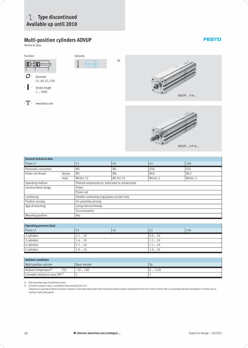
Multi-position cylinders ADVUPTechnical data
Function
-N- Diameter
25, 40, 63, 100
-T- Stroke length
1 … 2000
-W- www.festo.com
Variants
S6
ADVUP-…-P-A-…
ADVUP-…-A-P-A-…
General technical data
Piston ∅ 25 40 63 100
Pneumatic connection M5 M5 Gx G¼
Piston rod thread female M5 M8 M10 M12
male M10x1.25 M12x1.25 M16x1.5 M20x1.5
Operating medium Filtered compressed air, lubricated or unlubricated
Constructional design Pistong
Piston rod
Cushioning Flexible cushioning rings/plates at both ends
Position sensing For proximity sensing
Type of mounting Using internal threadsyp g
Via accessories
Mounting position Any
Operating pressure [bar]
Piston ∅ 25 40 63 100
2 cylinders 1.1 … 10 0.9 … 10
3 cylinders 1.4 … 10 1.2 … 10
4 cylinders 1.7 … 10 1.5 … 10
5 cylinders 2.0 … 10 1.8 … 10
Ambient conditions
Multi-position cylinder Basic version S6
Ambient temperature1) [°C] –20 … +80 0 … +120
Corrosion resistance class CRC2) 2 2
1) Note operating range of proximity sensors
2) Corrosion resistance class 2 according to Festo standard 940 070
Components requiring moderate corrosion resistance. Externally visible parts with primarily decorative surface requirements which are in direct contact with a surrounding industrial atmosphere or media such as
cooling or lubricating agents
-U- Type discontinuedAvailable up until 2010
2010/02 – Subject to change 29� Internet: www.festo.com/catalogue/...
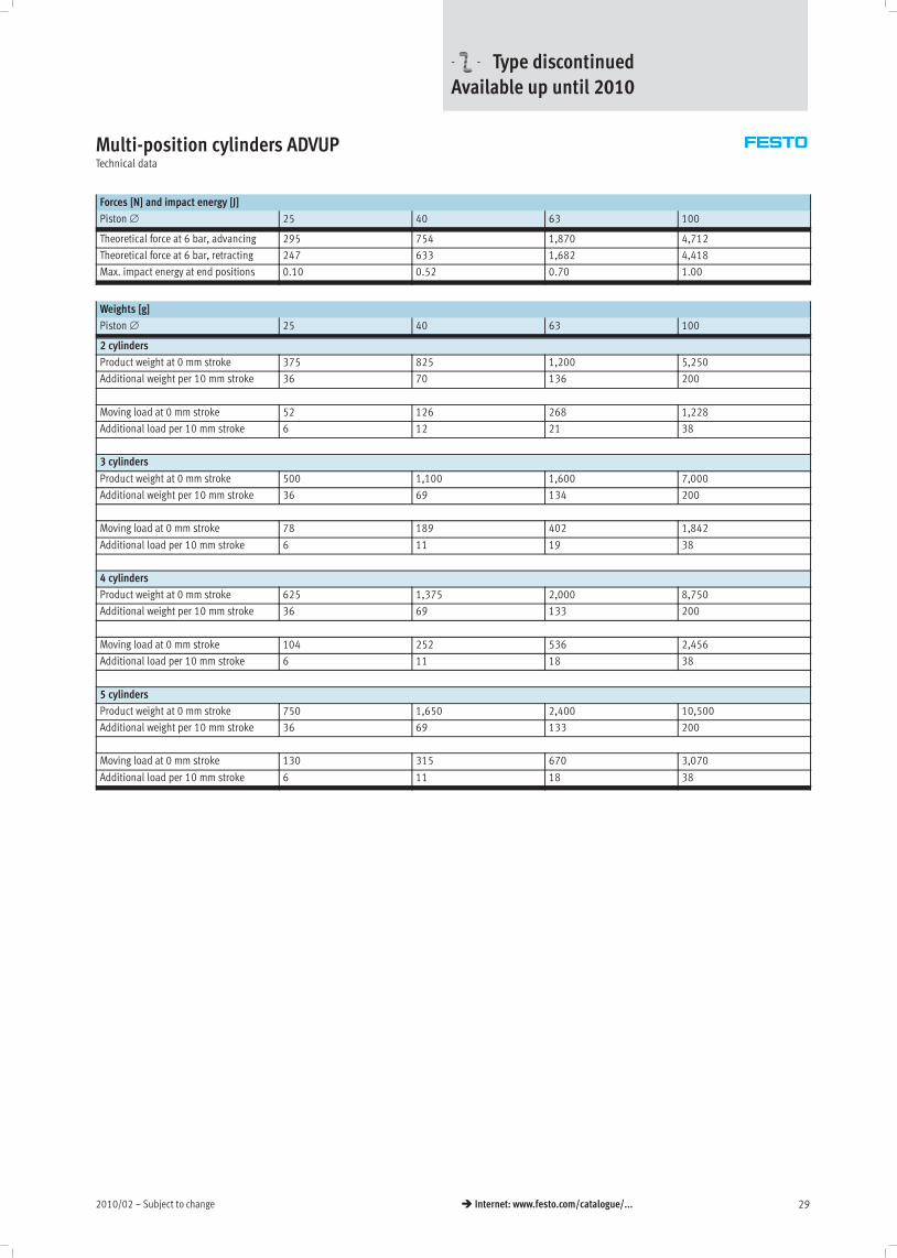
Multi-position cylinders ADVUPTechnical data
Forces [N] and impact energy [J]
Piston ∅ 25 40 63 100
Theoretical force at 6 bar, advancing 295 754 1,870 4,712
Theoretical force at 6 bar, retracting 247 633 1,682 4,418
Max. impact energy at end positions 0.10 0.52 0.70 1.00
Weights [g]
Piston ∅ 25 40 63 100
2 cylinders
Product weight at 0 mm stroke 375 825 1,200 5,250
Additional weight per 10 mm stroke 36 70 136 200
Moving load at 0 mm stroke 52 126 268 1,228
Additional load per 10 mm stroke 6 12 21 38
3 cylinders
Product weight at 0 mm stroke 500 1,100 1,600 7,000
Additional weight per 10 mm stroke 36 69 134 200
Moving load at 0 mm stroke 78 189 402 1,842
Additional load per 10 mm stroke 6 11 19 38
4 cylinders
Product weight at 0 mm stroke 625 1,375 2,000 8,750
Additional weight per 10 mm stroke 36 69 133 200
Moving load at 0 mm stroke 104 252 536 2,456
Additional load per 10 mm stroke 6 11 18 38
5 cylinders
Product weight at 0 mm stroke 750 1,650 2,400 10,500
Additional weight per 10 mm stroke 36 69 133 200
Moving load at 0 mm stroke 130 315 670 3,070
Additional load per 10 mm stroke 6 11 18 38
-U- Type discontinuedAvailable up until 2010
Subject to change – 2010/0230 � Internet: www.festo.com/catalogue/...
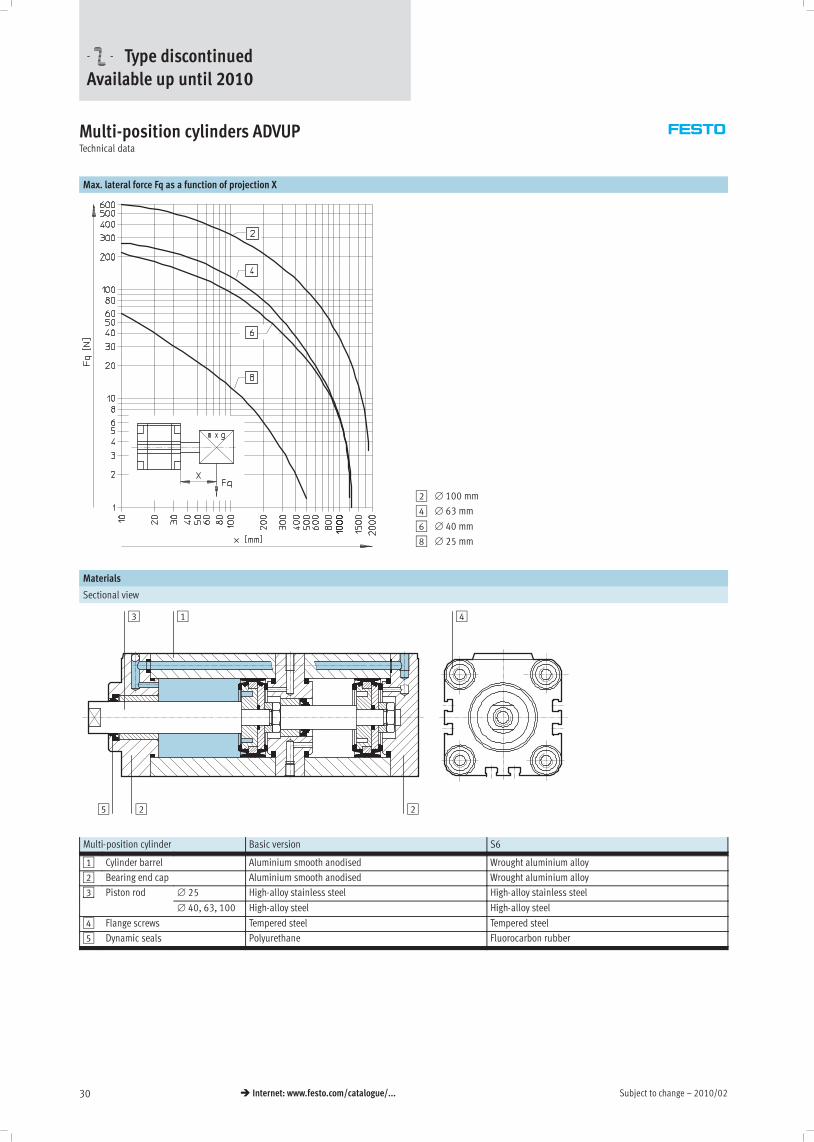
Multi-position cylinders ADVUPTechnical data
Max. lateral force Fq as a function of projection X
2 ∅ 100 mm
4 ∅ 63 mm
6 ∅ 40 mm
8 ∅ 25 mm
Materials
Sectional view
13
5 2 2
4
Multi-position cylinder Basic version S6
1 Cylinder barrel Aluminium smooth anodised Wrought aluminium alloy
2 Bearing end cap Aluminium smooth anodised Wrought aluminium alloy
3 Piston rod ∅ 25 High-alloy stainless steel High-alloy stainless steel3
∅ 40, 63, 100 High-alloy steel High-alloy steel
4 Flange screws Tempered steel Tempered steel
5 Dynamic seals Polyurethane Fluorocarbon rubber
-U- Type discontinuedAvailable up until 2010

2010/02 – Subject to change 31� Internet: www.festo.com/catalogue/...
Multi-position cylinders ADVUPTechnical data
Dimensions – Basic cylinder Download CAD data� www.festo.com
Piston ∅ 25 mm
1 Cylinder 1 advancing
6 Cylinder retracting
Piston ∅ 40, 63, 100 mm
1 Cylinder 1 advancing
6 Cylinder retracting
∅
[mm]
AF B
∅
BG D1
∅
H9
E EE H J3 KF
25 10 22 11 6 40 M5 1.5 – M5
40 12 35 15 6 60 M5 2.5 7.5 M8
63 16 42 23 8 87 Gx 4 10.5 M10
100 20 55 23 8 128 G¼ 5 14.5 M12
∅
[mm]
MM
∅
PL RT T2
–0.2
T4 TG VD ß1
h13
25 10 8 M5 4 2 26 4 9
40 16 8 M6 4 3.3 42 7 13
63 20 8 M10 4 4.7 62 11.5 17
100 25 10.5 M10 4 6.1 103 15 22
-U- Type discontinuedAvailable up until 2010
Subject to change – 2010/0232 � Internet: www.festo.com/catalogue/...
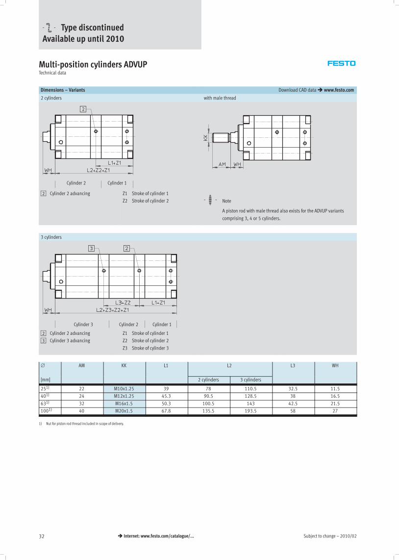
Multi-position cylinders ADVUPTechnical data
Dimensions – Variants Download CAD data� www.festo.com
2 cylinders with male thread
Cylinder 1Cylinder 2
2 Cylinder 2 advancing Z1 Stroke of cylinder 1
Z2 Stroke of cylinder 2 -H- Note
A piston rod with male thread also exists for the ADVUP variants
comprising 3, 4 or 5 cylinders.
3 cylinders
Cylinder 2Cylinder 3 Cylinder 1
2 Cylinder 2 advancing
3 Cylinder 3 advancing
Z1 Stroke of cylinder 1
Z2 Stroke of cylinder 2
Z3 Stroke of cylinder 3
∅ AM KK L1 L2 L3 WH
[mm] 2 cylinders 3 cylinders
251) 22 M10x1.25 39 78 110.5 32.5 11.5
401) 24 M12x1.25 45.3 90.5 128.5 38 16.5
631) 32 M16x1.5 50.3 100.5 143 42.5 21.5
1001) 40 M20x1.5 67.8 135.5 193.5 58 27
1) Nut for piston rod thread included in scope of delivery.
-U- Type discontinuedAvailable up until 2010

2010/02 – Subject to change 33� Internet: www.festo.com/catalogue/...
Multi-position cylinders ADVUPTechnical data
Dimensions – Variants Download CAD data� www.festo.com
4 cylinders
Cylinder 4 Cylinder 3 Cylinder 2 Cylinder 1
2 Cylinder 2 advancing
3 Cylinder 3 advancing
4 Cylinder 4 advancing
Z1 Stroke of cylinder 1
Z2 Stroke of cylinder 2
Z3 Stroke of cylinder 3
Z4 Stroke of cylinder 4
5 cylinders
Cylinder 5 Cylinder 4 Cylinder 3 Cylinder 2 Cylinder 1
2 Cylinder 2 advancing
3 Cylinder 3 advancing
4 Cylinder 4 advancing
5 Cylinder 5 advancing
Z1 Stroke of cylinder 1
Z2 Stroke of cylinder 2
Z3 Stroke of cylinder 3
Z4 Stroke of cylinder 4
Z5 Stroke of cylinder 5
∅ L1 L2 L3 WH
[mm] 4 cylinders 5 cylinders
251) 39 143 175.5 32.5 11.5
401) 45.3 166.5 204.5 38 16.5
631) 50.3 185.5 228 42.5 21.5
1001) 67.8 251.5 309.5 58 27
1) Nut for piston rod thread included in scope of delivery.
-U- Type discontinuedAvailable up until 2010

Subject to change – 2010/0234 � Internet: www.festo.com/catalogue/...
Multi-position cylinders ADVUP, female threadOrdering data – Modular product system
Mandatory data0M Options0O
Module No. Drive
system
Size Cushioning Position
sensing
Mid-position Temperature-
resistantsystem sensing
1 2 3 4 5
resistant
161 147
161 148
161 149
161 150
ADVUP 25
40
63
100
P A …Z1 …Z2 …Z3 …Z4 …Z5 S6
Ordering
example
161 147 ADVUP – 25 – P – A – 40Z1 – 95Z2 – – – – S6
Ordering table
Size 25 40 63 100 Condi-
tions
Code Enter
code
0M Module No. 161 147 161 148 161 149 161 150
Drive system Compact multi-position cylinders ADVUP ADVUP
Size 25 40 63 100 -…
Cushioning Flexible cushioning rings/plates at both ends -P -P
Position sensing For proximity sensing -A -A
1. Mid-position [mm] 1 … 200 1 … 300 1 … 300 1 … 400 1 -…Z1
2. Mid-position [mm] 1 … 300 1 … 1000 1 … 1000 1 … 1000 12 -…Z2
0O 3. Mid-position [mm] 1 … 300 1 … 1000 1 … 1000 1 … 1000 12 -…Z3
4. Mid-position [mm] 1 … 300 1 … 1000 1 … 1000 1 … 1000 12 -…Z4
5. Mid-position [mm] 1 … 300 1 … 1000 1 … 1000 1 … 1000 12 -…Z5
Temperature-resistant Heat-resistant seals to max. 120° C -S6
1 Z1 … Z5 For the selected mid-positions the following must apply:
The end of the retracted piston rod is the reference point for all
mid-positions!
Z1 < Z2 < Z3 < Z4 < Z5: each subsequent mid-position must be
larger than the one that precedes it.
Maximum overall length (sum of all individual strokes):
Z1 + Z2 + Z3 + Z4 + Z5 ≤ 1000 mm at ∅ 25
Z1 + Z2 + Z3 + Z4 + Z5 ≤ 2000 mm at ∅ 40 … 100.
2 Z2 … Z5 Max. permissible stroke except for the last position (visible piston
rod) in mm:
200 mm for ∅ 25;
300 mm for ∅ 40, 63;
400 mm for ∅ 100.
Transfer order code
ADVUP – – P – A – – – – – –
-U- Type discontinuedAvailable up until 2010

2010/02 – Subject to change 35� Internet: www.festo.com/catalogue/...
Multi-position cylinders ADVUP, male threadOrdering data – Modular product system
Mandatory data0M Options0O
Module No. Drive
system
Size Thread
type
Cushion-
ing
Position
sensing
Mid-position Temperature-
resistantsystem type ing sensing
1 2 3 4 5
resistant
197 277
197 278
197 279
197 280
ADVUP 25
40
63
100
A P A …Z1 …Z2 …Z3 …Z4 …Z5 S6
Ordering
example
197 278 ADVUP – 25 – A – P – A – 20Z1 – – – – –
Ordering table
Size 25 40 63 100 Condi-
tions
Code Enter
code
0M Module No. 197 277 197 278 197 279 197 280
Drive system Compact multi-position cylinders ADVUP ADVUP
Size 25 40 63 100 -…
Thread type Male thread -A -A
Cushioning Flexible cushioning rings/plates at both ends -P -P
Position sensing For proximity sensing -A -A
1. Mid-position [mm] 1 … 200 1 … 300 1 … 300 1 … 400 1 -…Z1
2. Mid-position [mm] 1 … 300 1 … 1000 1 … 1000 1 … 1000 12 -…Z2
0O 3. Mid-position [mm] 1 … 300 1 … 1000 1 … 1000 1 … 1000 12 -…Z3
4. Mid-position [mm] 1 … 300 1 … 1000 1 … 1000 1 … 1000 12 -…Z4
5. Mid-position [mm] 1 … 300 1 … 1000 1 … 1000 1 … 1000 12 -…Z5
Temperature-resistant Heat-resistant seals to max. 120° C -S6
1 Z1 … Z5 For the selected mid-positions the following must apply:
The end of the retracted piston rod is the reference point for all
mid-positions!
Z1 < Z2 < Z3 < Z4 < Z5: each subsequent mid-position must be
larger than the one that precedes it.
Maximum overall length (sum of all individual strokes):
Z1 + Z2 + Z3 + Z4 + Z5 ≤ 1000 mm at ∅ 25
Z1 + Z2 + Z3 + Z4 + Z5 ≤ 2000 mm at ∅ 40 … 100.
2 Z2 … Z5 Max. permissible stroke except for the last mid-position (visible
piston rod) in mm:
200 mm for ∅ 25;
300 mm for ∅ 40, 63;
400 mm for ∅ 100.
Transfer order code
ADVUP – – A – P – A – – – – – –
-U- Type discontinuedAvailable up until 2010

Subject to change – 2010/0236 � Internet: www.festo.com/catalogue/...
Multi-position cylinders ADVUPAccessories
Foot mounting HUA
Material:
Galvanised steel
Free of copper, PTFE and silicone
+ = plus stroke lengths
Dimensions and ordering data
For ∅ AB AH AO AT AU SA TR
∅ 2 cylinders1) 3 cylinders2) 4 cylinders3) 5 cylinders4)
25 6.6 29 6.25 4 16 110 142.5 175 207.5 26
40 9 40.5 8.25 5 20 130.5 168.5 206.5 244.5 42
63 11 56.5 11.75 6 27 154.5 197 239.5 282 62
100 13.5 81 11.75 8 33 201.5 259.5 317.5 375.5 103
For ∅ US XA CRC5) Weight Part No. Type
2 cylinders1) 3 cylinders2) 4 cylinders3) 5 cylinders4) [g]
25 38 105.5 138 170.5 203 2 90 157 311 HUA-25
40 58 127 165 203 241 2 201 157 313 HUA-40
63 85 149 191.5 234 276.5 2 550 157 315 HUA-63
100 126 195.5 253.5 311.5 369.5 2 1,050 157 317 HUA-100
1) plus stroke length X1+X2
2) plus stroke length X1+X2+X3
3) plus stroke length X1+X2+X3+X4
4) plus stroke length X1+X2+X3+X4+X5
5) Corrosion resistance class 2 according to Festo standard 940 070
Components requiring moderate corrosion resistance. Externally visible parts with primarily decorative surface requirements which are in direct contact with a surrounding industrial atmosphere or media such as
cooling or lubricating agents
-U- Type discontinuedAvailable up until 2010
2010/02 – Subject to change 37� Internet: www.festo.com/catalogue/...
Multi-position cylinders ADVUPAccessories
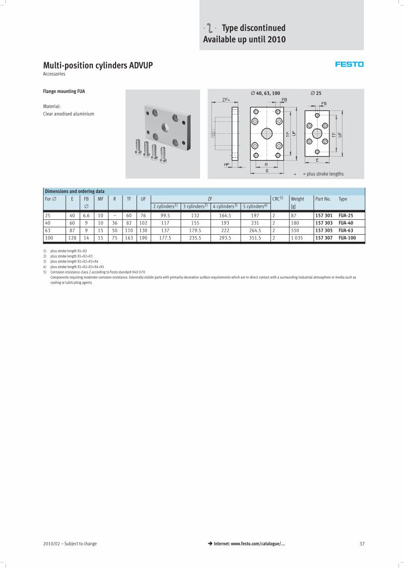
Flange mounting FUA
Material:
Clear anodised aluminium
∅ 25
+ = plus stroke lengths
∅ 40, 63, 100
Dimensions and ordering data
For ∅ E FB MF R TF UF ZF CRC5) Weight Part No. Type
∅ 2 cylinders1) 3 cylinders2) 4 cylinders3) 5 cylinders4) [g]
25 40 6.6 10 – 60 76 99.5 132 164.5 197 2 87 157 301 FUA-25
40 60 9 10 36 82 102 117 155 193 231 2 180 157 303 FUA-40
63 87 9 15 50 110 130 137 179.5 222 264.5 2 550 157 305 FUA-63
100 128 14 15 75 163 190 177.5 235.5 293.5 351.5 2 1 035 157 307 FUA-100
1) plus stroke length X1+X2
2) plus stroke length X1+X2+X3
3) plus stroke length X1+X2+X3+X4
4) plus stroke length X1+X2+X3+X4+X5
5) Corrosion resistance class 2 according to Festo standard 940 070
Components requiring moderate corrosion resistance. Externally visible parts with primarily decorative surface requirements which are in direct contact with a surrounding industrial atmosphere or media such as
cooling or lubricating agents
-U- Type discontinuedAvailable up until 2010
Subject to change – 2010/0238 � Internet: www.festo.com/catalogue/...
Multi-position cylinders ADVUPAccessories
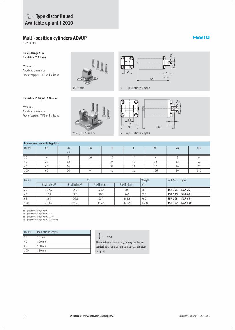
Swivel flange SUA
for piston∅ 25 mm
Material:
Anodised aluminium
Free of copper, PTFE and silicone
∅ 25 mm + = plus stroke lengths
for piston∅ 40, 63, 100 mm
Material:
Anodised aluminium
Free of copper, PTFE and silicone
∅ 40, 63, 100 mm + = plus stroke lengths
Dimensions and ordering data
For ∅ CB CD EW FL L ML MR UB
∅
25 – 8 16 20 14 – 8 –
40 28 12 – 25 16 62 12 52
63 40 16 – 32 21 82 16 70
100 60 20 – 41 26 126 20 110
For ∅ XC Weight Part No. Type
2 cylinders1) 3 cylinders2) 4 cylinders3) 5 cylinders4) [g]
25 109.5 142 174.5 207 86 157 321 SUA-25
40 132 170 208 246 320 157 323 SUA-40
63 154 196.5 239 281.5 760 157 325 SUA-63
100 203.5 261.5 319.5 377.5 1 900 157 327 SUA-100
1) plus stroke length X1+X2
2) plus stroke length X1+X2+X3
3) plus stroke length X1+X2+X3+X4
4) plus stroke length X1+X2+X3+X4+X5
For ∅ Max. stroke length
HH25 50 mm -H- Note
40 100 mm
HThe maximum stroke length may not be ex-
63 100 mm
The maximum stroke length may not be ex
ceeded when combining cylinders and swivel
100 150 mm
ceeded when combining cylinders and swivel
flanges.flanges.
-U- Type discontinuedAvailable up until 2010
2010/02 – Subject to change 39� Internet: www.festo.com/catalogue/...
Multi-position cylinders ADVUPAccessories
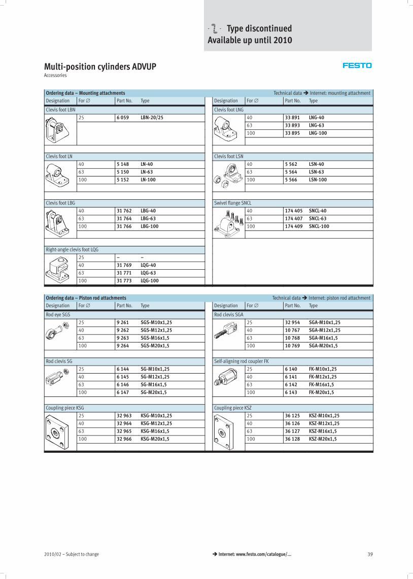
Ordering data – Mounting attachments Technical data� Internet: mounting attachment
Designation For ∅ Part No. Type Designation For ∅ Part No. Type
Clevis foot LBN Clevis foot LNG
25 6 059 LBN-20/25 40 33 891 LNG-40
63 33 893 LNG-63
100 33 895 LNG-100
Clevis foot LN Clevis foot LSN
40 5 148 LN-40 40 5 562 LSN-40
63 5 150 LN-63 63 5 564 LSN-63
100 5 152 LN-100 100 5 566 LSN-100
Clevis foot LBG Swivel flange SNCL
40 31 762 LBG-40 40 174 405 SNCL-40
63 31 764 LBG-63 63 174 407 SNCL-63
100 31 766 LBG-100 100 174 409 SNCL-100
Right-angle clevis foot LQG
25 – –
40 31 769 LQG-40
63 31 771 LQG-63
100 31 773 LQG-100
Ordering data – Piston rod attachments Technical data� Internet: piston rod attachment
Designation For ∅ Part No. Type Designation For ∅ Part No. Type
Rod eye SGS Rod clevis SGA
25 9 261 SGS-M10x1,25 25 32 954 SGA-M10x1,25
40 9 262 SGS-M12x1,25 40 10 767 SGA-M12x1,25
63 9 263 SGS-M16x1,5 63 10 768 SGA-M16x1,5
100 9 264 SGS-M20x1,5 100 10 769 SGA-M20x1,5
Rod clevis SG Self-aligning rod coupler FK
25 6 144 SG-M10x1,25 25 6 140 FK-M10x1,25
40 6 145 SG-M12x1,25 40 6 141 FK-M12x1,25
63 6 146 SG-M16x1,5 63 6 142 FK-M16x1,5
100 6 147 SG-M20x1,5 100 6 143 FK-M20x1,5
Coupling piece KSG Coupling piece KSZ
25 32 963 KSG-M10x1,25 25 36 125 KSZ-M10x1,25
40 32 964 KSG-M12x1,25 40 36 126 KSZ-M12x1,25
63 32 965 KSG-M16x1,5 63 36 127 KSZ-M16x1,5
100 32 966 KSG-M20x1,5 100 36 128 KSZ-M20x1,5
-U- Type discontinuedAvailable up until 2010

Subject to change – 2010/0240 � Internet: www.festo.com/catalogue/...
Multi-position cylinders ADVUPAccessories
Ordering data – Proximity sensors for T-slot, magneto-resistive Technical data� Internet: smt
Type of mounting Switch Electrical connection Cable length Part No. Typeyp g
output [m]
yp
N/O contact
Insertable in the slot from above, flush PNP Cable, 3-wire 2.5 543 867 SMT-8M-PS-24V-K-2,5-OE,
with cylinder profile Plug M8x1, 3-pin 0.3 543 866 SMT-8M-PS-24V-K-0,3-M8Dy p
Plug M12x1, 3-pin 0.3 543 869 SMT-8M-PS-24V-K-0,3-M12
NPN Cable, 3-wire 2.5 543 870 SMT-8M-NS-24V-K-2,5-OE
Plug M8x1, 3-pin 0.3 543 871 SMT-8M-NS-24V-K-0,3-M8D
Insertable in the slot lengthwise, flush PNP Cable, 3-wire 2.5 175 436 SMT-8-PS-K-LED-24-Bg ,
with the cylinder profile Plug M8x1, 3-pin 0.3 175 484 SMT-8-PS-S-LED-24-B
N/C contact
Insertable in the slot from above, flush
with cylinder profile
PNP Cable, 3-wire 7.5 543 873 SMT-8M-PO-24V-K7,5-OE
Ordering data – Proximity sensors for T-slot, magnetic reed Technical data� Internet: sme
Type of mounting Switch Electrical connection Cable length Part No. Typeyp g
output [m]
yp
N/O contact
Insertable in the slot from above, flush Contacting Cable, 3-wire 2.5 543 862 SME-8M-DS-24V-K-2,5-OE,
with cylinder profile
g , 3
5.0 543 863 SME-8M-DS-24V-K-5,0-OEy p
Cable, 3-wire 2.5 543 872 SME-8M-ZS-24V-K-2,5-OE
Plug M8x1, 3-pin 0.3 543 861 SME-8M-DS-24V-K-0,3-M8D
Insertable in the slot lengthwise, flush Contacting Cable, 3-wire 2.5 150 855 SME-8-K-LED-24g ,
with the cylinder profile
g
Plug M8x1, 3-pin 0.3 150 857 SME-8-S-LED-24
N/C contact
Insertable in the slot lengthwise, flush
with the cylinder profile
Contacting Cable, 3-wire 7.5 160 251 SME-8-O-K-LED-24
Ordering data – Connecting cables Technical data� Internet: nebu
Electrical connection, left Electrical connection, right Cable length Part No. Type, , g
[m]
yp
Straight socket, M8x1, 3-pin Cable, open end, 3-wire 2.5 541 333 NEBU-M8G3-K-2.5-LE3g , , 3 p , p , 3
5 541 334 NEBU-M8G3-K-5-LE3
Straight socket, M12x1, 5-pin Cable, open end, 3-wire 2.5 541 363 NEBU-M12G5-K-2.5-LE3g , , 5 p , p , 3
5 541 364 NEBU-M12G5-K-5-LE3
Angled socket, M8x1, 3-pin Cable, open end, 3-wire 2.5 541 338 NEBU-M8W3-K-2.5-LE3g , , 3 p , p , 3
5 541 341 NEBU-M8W3-K-5-LE3
Angled socket, M12x1, 5-pin Cable, open end, 3-wire 2.5 541 367 NEBU-M12W5-K-2.5-LE3g , , 5 p , p , 3
5 541 370 NEBU-M12W5-K-5-LE3
Ordering data – Slot cover for T-slot
Mounting Length Part No. Type
Insertable from
above
2x 0.5 m 151 680 ABP-5-S
-U- Type discontinuedAvailable up until 2010
2010/02 – Subject to change 41� Internet: www.festo.com/catalogue/...
Multi-position cylinders ADVUPAccessories
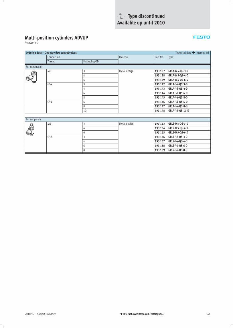
Ordering data – One-way flow control valves Technical data� Internet: grl
Connection Material Part No. Type
Thread For tubing OD
yp
For exhaust air
M5 3 Metal design 193 137 GRLA-M5-QS-3-D5
4
g
193 138 GRLA-M5-QS-4-D
6 193 139 GRLA-M5-QS-6-D
Gx 3 193 142 GRLA-x-QS-3-Dx
4 193 143 GRLA-x-QS-4-D
6 193 144 GRLA-x-QS-6-D
8 193 145 GRLA-x-QS-8-D
G¼ 6 193 146 GRLA-¼-QS-6-D¼
8 193 147 GRLA-¼-QS-8-D
10 193 148 GRLA-¼-QS-10-D
For supply air
M5 3 Metal design 193 153 GRLZ-M5-QS-3-D5
4
g
193 154 GRLZ-M5-QS-4-D
6 193 155 GRLZ-M5-QS-6-D
Gx 3 193 156 GRLZ-x-QS-3-Dx
4 193 157 GRLZ-x-QS-4-D
6 193 158 GRLZ-x-QS-6-D
8 193 159 GRLZ-x-QS-8-D
-U- Type discontinuedAvailable up until 2010
Subject to change – 2010/0242 � Internet: www.festo.com/catalogue/...
Adapter kits DPNC/DPNG, standard port patternTechnical data
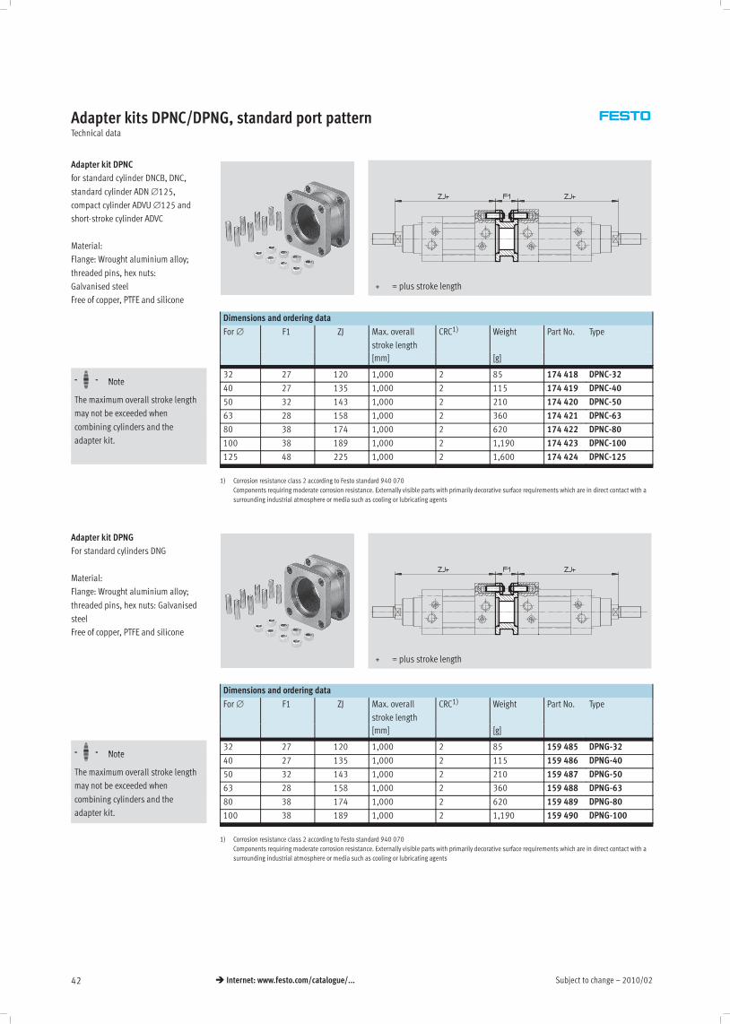
Adapter kit DPNC
for standard cylinder DNCB, DNC,
standard cylinder ADN ∅125,
compact cylinder ADVU ∅125 and
short-stroke cylinder ADVC
Material:
Flange: Wrought aluminium alloy;
threaded pins, hex nuts:
Galvanised steel
F f PTFE d ili
+ = plus stroke length
Free of copper, PTFE and silicone
Dimensions and ordering data
For ∅ F1 ZJ Max. overall
stroke length
CRC1) Weight Part No. Type
[mm] [g]
-H- Note32 27 120 1,000 2 85 174 418 DPNC-32-H- Note40 27 135 1,000 2 115 174 419 DPNC-40
The maximum overall stroke length 50 32 143 1,000 2 210 174 420 DPNC-50may not be exceeded when 63 28 158 1,000 2 360 174 421 DPNC-63combining cylinders and the 80 38 174 1,000 2 620 174 422 DPNC-80adapter kit. 100 38 189 1,000 2 1,190 174 423 DPNC-100
125 48 225 1,000 2 1,600 174 424 DPNC-125
1) Corrosion resistance class 2 according to Festo standard 940 070
Components requiring moderate corrosion resistance. Externally visible parts with primarily decorative surface requirements which are in direct contact with a
surrounding industrial atmosphere or media such as cooling or lubricating agents
Adapter kit DPNG
For standard cylinders DNG
Material:
Flange: Wrought aluminium alloy;
threaded pins, hex nuts: Galvanised
steel
Free of copper, PTFE and silicone
+ = plus stroke length
Dimensions and ordering data
For ∅ F1 ZJ Max. overall
stroke length
CRC1) Weight Part No. Type
[mm] [g]
-H- Note32 27 120 1,000 2 85 159 485 DPNG-32-H- Note40 27 135 1,000 2 115 159 486 DPNG-40
The maximum overall stroke length 50 32 143 1,000 2 210 159 487 DPNG-50may not be exceeded when 63 28 158 1,000 2 360 159 488 DPNG-63combining cylinders and the 80 38 174 1,000 2 620 159 489 DPNG-80adapter kit. 100 38 189 1,000 2 1,190 159 490 DPNG-100
1) Corrosion resistance class 2 according to Festo standard 940 070
Components requiring moderate corrosion resistance. Externally visible parts with primarily decorative surface requirements which are in direct contact with a
surrounding industrial atmosphere or media such as cooling or lubricating agents

2010/02 – Subject to change 43� Internet: www.festo.com/catalogue/...
Adapter kits DPNA/DPVUTechnical data
Adapter kit DPNA
for standard cylinder ADN
Material:
Flange: Aluminium
Screws: Galvanised steel
Free of copper, PTFE and silicone
+ = plus stroke length
Dimensions and ordering data
For ∅ B1 L2 Max. overall stroke
length
CRC1) Part No. Type
[mm]
-H- Note12 13 35 600 2 537 263 DPNA-12 -V--H- Note16 13 35 600 2 537 264 DPNA-16 -V-
The maximum overall stroke length 20 13 37 600 2 537 265 DPNA-20 -V-
may not be exceeded when 25 13 39 600 2 537 266 DPNA-25 -V-
combining cylinders and the 32 15 44 800 2 537 267 DPNA-32 -V-
adapter kit. 40 15 45 800 2 537 268 DPNA-40 -V-
50 15 45 800 2 537 269 DPNA-50 -V-
63 15 49 800 2 537 270 DPNA-63 -V-
80 17 54 1,000 2 537 271 DPNA-80 -V-
100 19,5 67 1,000 2 537 272 DPNA-100 -V-
1) Corrosion resistance class 2 according to Festo standard 940 070
Components requiring moderate corrosion resistance. Externally visible parts with primarily decorative surface requirements which are in direct contact with a
surrounding industrial atmosphere or media such as cooling or lubricating agents
Adapter kit DPVU
for compact cylinder ADVU
Material:
Flange: Aluminium
Screws: Galvanised steel
Free of copper, PTFE and silicone
+ = plus stroke length
Dimensions and ordering data
For ∅ B1 H Max. overall
stroke length
CRC1) Weight Part No. Type
[mm] [g]
-H- Note12/16 12,5 38 400 2 22 161 194 DPVU-12/16-H- Note20 12,5 38 400 2 36 161 195 DPVU-20
The maximum overall stroke length 25 13 39,5 400 2 44 161 196 DPVU-25may not be exceeded when 32 14,5 44,5 600 2 90 161 197 DPVU-32combining cylinders and the 40 14,5 45,5 600 2 137 161 198 DPVU-40adapter kit. 50 14,5 45,5 600 2 177 161 199 DPVU-50
63 14,5 50 600 2 308 161 200 DPVU-63
80 16,5 56 800 2 495 161 201 DPVU-80
100 19,5 66,5 800 2 859 161 202 DPVU-100
1) Corrosion resistance class 2 according to Festo standard 940 070
Components requiring moderate corrosion resistance. Externally visible parts with primarily decorative surface requirements which are in direct contact with a
surrounding industrial atmosphere or media such as cooling or lubricating agents
-V- New