Embed Size (px)
Citation preview
J Intell Robot SystDOI 10.1007/s10846-016-0375-7
Multi-Robot Localization and Mapping Based on SignedDistance Functions
Philipp Koch · Stefan May ·Michael Schmidpeter ·Markus Kuhn ·Christian Pfitzner ·Christian Merkl ·Rainer Koch ·Martin Fees ·Jon Martin ·Daniel Ammon ·Andreas Nuchter
Received: 7 June 2015 / Accepted: 1 May 2016© Springer Science+Business Media Dordrecht 2016
Abstract This publication describes a 2D Simultane-ous Localization and Mapping approach applicable tomultiple mobile robots. The presented strategy usesdata of 2D LIDAR sensors to build a dynamic repre-sentation based on Signed Distance Functions. Nov-elties of the approach are a joint map built in parallelinstead of occasional merging of smaller maps and thelimited drift localization which requires no loop clo-sure detection. A multi-threaded software architectureperforms registration and data integration in parallelallowing for drift-reduced pose estimation of multiplerobots. Experiments are provided demonstrating theapplication with single and multiple robot mappingusing simulated data, public accessible recorded data,two actual robots operating in a comparably large areaas well as a deployment of these units at the Robocuprescue league.
Keywords Mobile robotics · Multi-robot · Rescuerobotics · SLAM
P. Koch (�) · S. May · M. Schmidpeter · M. Kuhn ·C. Pfitzner · C. Merkl · R. Koch · M. Fees · J. Martin ·D. AmmonFaculty of Electrical Engineering, Precision Engineering,Information Technology, Nuremberg Institute of TechnologyGeorg Simon Ohm, Nuremberg, Germanye-mail: [email protected]
A. NuchterInformatics VII: Robotics and Telematics,University Wuerzburg, Wurzburg, Germany
1 Introduction
Rescue forces risk their own health and life in servicefor people in serious trouble. In collapsed or burningbuildings the search for victims is dangerous and timecritical.
In general, such disaster sites can be assumed asunknown areas wherefore the search for injured ortrapped persons is an exploration task in the first place.Included autonomous robots face the well-knownSimultaneous Localization and Mapping (SLAM)problem.
The chance to save lives reduces gradually in time,wherefore multiple rescue forces searching in paral-lel increase the efficiency. In order to support humanteams in dangerous tasks with multiple robots, coordi-nation and data fusion is mandatory to defragment col-lected sensor data of several robots. Piecing togetherthese fragments is required for getting a general ideaabout the whole situation. Rescue forces are instructedmore efficiently having the global overview.
The invention of robots capable of deployment inrescue scenarios is a complicated and therefore expen-sive task. Inspired by catastrophes resulting in hugeamounts of injured or buried people, the Robocuprescue league was founded.
This organisation aims at turning rescue roboticsinto a world wide open source project. In general,teams of students working at universities or insti-tutes of technology create robots which participate atnational and international competitions. After these
J Intell Robot Syst
events, the teams publish their results and allow publicaccess to their software, mechanical design and othertechnical details.
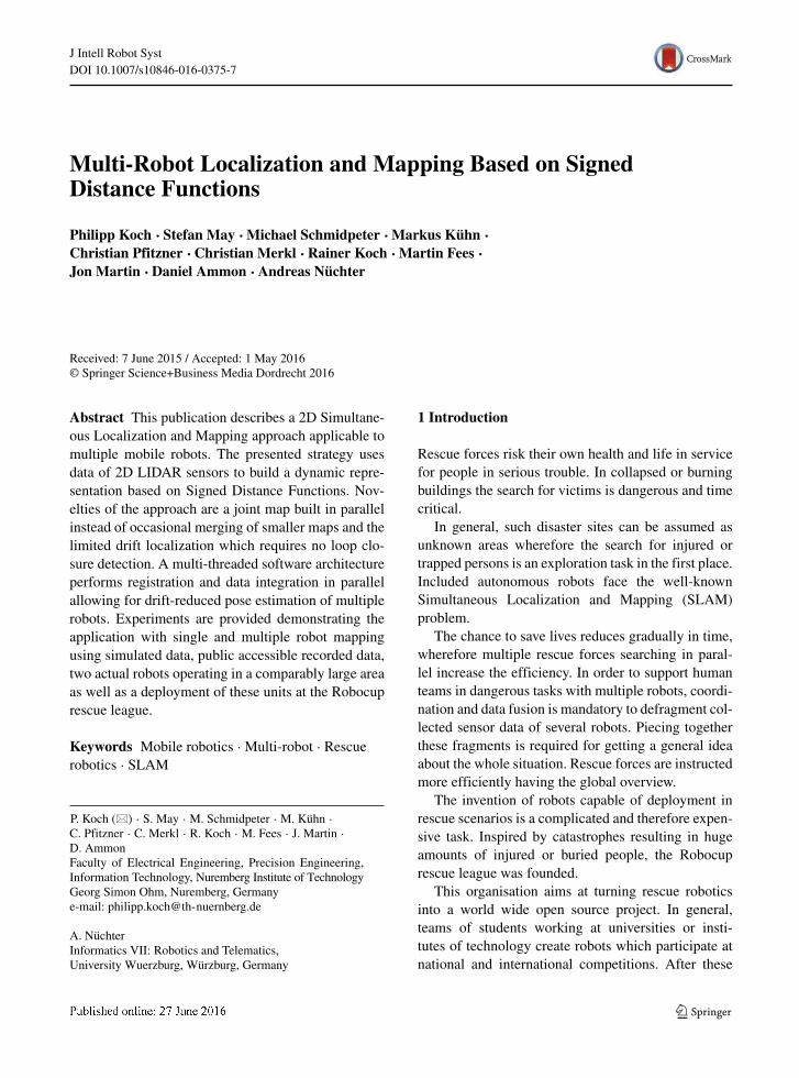
This leads to a world wide open source commu-nity as all teams can base further research on theseresults. Examples for robots competing in this leagueare illustrated in Fig. 1.
In order to simulate a disaster scenario at theRobocup rescue competition, a maze is used consist-ing of standardized components such as ramps, stairsor random step fields. In the future, 3D perception willbe necessary in order to create a system capable ofprevailing in a real scenario but currently 2D localiza-tion and mapping is sufficient for the Robocup rescueleague.
In this paper, we propose a 2D multi-SLAM frame-work allowing a robot team to cooperate together fordrift-reduced pose estimation and shared mapping inthe Robocup rescue competition. A main novelty com-pared to other approaches is the joint map built inparallel by the cooperating robots.
A multi-threaded software architecture allows par-allel pose estimation of multiple 2D LIDAR inputs.Either a shared map or individual maps can be usedfor all robot instances.
One could mention that a 2D algorithm is not suf-ficient regarding the comparably structured area ofa search and rescue site. Nevertheless the proposedapproach aims at deployment in the Robocup rescueleague for which 2D perception is currently sufficient.
The content of this paper is structured as fol-lows: Section 2 reviews related work in multi-robotSLAM. Section 3 outlines the proposed frameworkand develops the concrete model for including 2Dlaser scanners. Section 4 extends the framework for
application to multi-robot SLAM. In Section 5 single-robot and multi-robot SLAM experiments are per-formed, either in simulation and in a real world sce-nario. In Section 6, the application of the approach atthe Robocup German Open 2015 is described. Finally,Section 7 concludes with an outlook on future work.
This paper is an extension of already publishedwork [11]. The extensions consist of a ground truthanalysis concerning public available reference data,as well as simulated data. The multi-SLAM has beendeployed at the Robocup German Open, whereforethe paper contains data of the competition as well aslessons learned. The framework has been comparedto the current state of the art 2D-SLAM approach atthe Robocup, using similar parameters and the sameinput data. Additionally, the multi-SLAM experimentdeplyoing a team of two robots has been enhancedwith a timing analysis of the framework.
2 Related Work
In an early approach, Burgard et al. considered mul-tiple robots as independent systems to be coordinatedfor a faster coverage of the exploration area [3]. Theglobal map is a result of integrating several local maps.If their relative poses are known, map integration isstraightforward. While focusing on the collaborationaspect, an extended approach still makes need of closeinitial robot poses [4].
Several probabilistic models were proposed tosolve the problem of unknown starting poses of multi-ple robots in a joined exploration task. Konolige et al.used local probabilistic constraints among robot poses[13]. Each pair of the robot team exchanges local
Fig. 1 Cooperating Robotsat the Robocup GermanOpen 2014
J Intell Robot Syst
maps for merging both to obtain a globally consistentmap with loop-closure techniques. Howard proposedRao-Blackwellized particle filters for the localizationproblem [8]. Local maps are merged in case robotscome close to each other during mission.
Fox et al. demonstrated the efficient exploration ofunknown environments by a team of mobile robots[6]. Also this approach does not rely on initial poseinformation about the robot team members. Havingthe ability to explore independently, the robots canbuild clusters in order to share a map as soon as theycome close enough for establishing stable communi-cation links. The robots need to determine their poserelative to the coordinate system of the shared map.Particle filters are employed for this task on eachrobot. The proposed approach works efficiently forup to six robots. Global consistency is ensured by theapplication of loop-closure techniques.
The approach of Kim et al. relies on multiple rela-tive pose graphs for the cooperative mapping task witha team of mobile robots [10]. Real-time applicabilitywas achieved as well as fast convergence to a globalsolution. The approach also employs loop-closuredetection. Kim et al. illustrated the performance inlarger environments, of which several thousand laserscans were provided. Different kinematic conceptswere included, e.g., the cooperative mapping using aquadrotor and a ground robot.
Granstrom et al. proposed the detection of loop clo-sures with a machine learning approach [7]. The groupused AdaBoost for building rotation invariant featuresdetected in laser scans.
In 2D SLAM approaches loop-closure detectionplays an important role. Interestingly, the 3D SLAMapproach KinectFusion has no need to rely on thisstep. Izadi et al. demonstrated that the representationof a Signed Distance Function (SDF) [16] appliedto the SLAM problem, achieves accurate trackingresults with limited drift [9]. The group achievedreal-time capability by the use of massive paral-lelism on GPU. A hand-held Kinect was localizedby Iterative Closest Point (ICP) registration whiletracking against the growing full surface model. Theconvergence of the system without explicit globaloptimization was demonstrated in several closed-loop scenarios. This approach aims at the assimi-lation of as many surface measurements as possi-ble in time and features a limited drift and highaccuracy.
In a previous publication, we generalized theKinectFusion approach in order to make it applicableto different types of sensors, e.g., 2D and 3D laserscanners, Time-of-Flight and stereo cameras or struc-tured light sensors [15]. In this publication we extendthis framework for the SLAM problem performed bymultiple robots. The approach can either be appliedto several robots independently or to a team of robotssharing and updating a joined map.
3 Algorithm
For the reader’s convenience, this section containsapplication of the generic framework to 2D laser scan-ners [15]. The multi-robot extension and closed-loopexperiments follow subsequently.
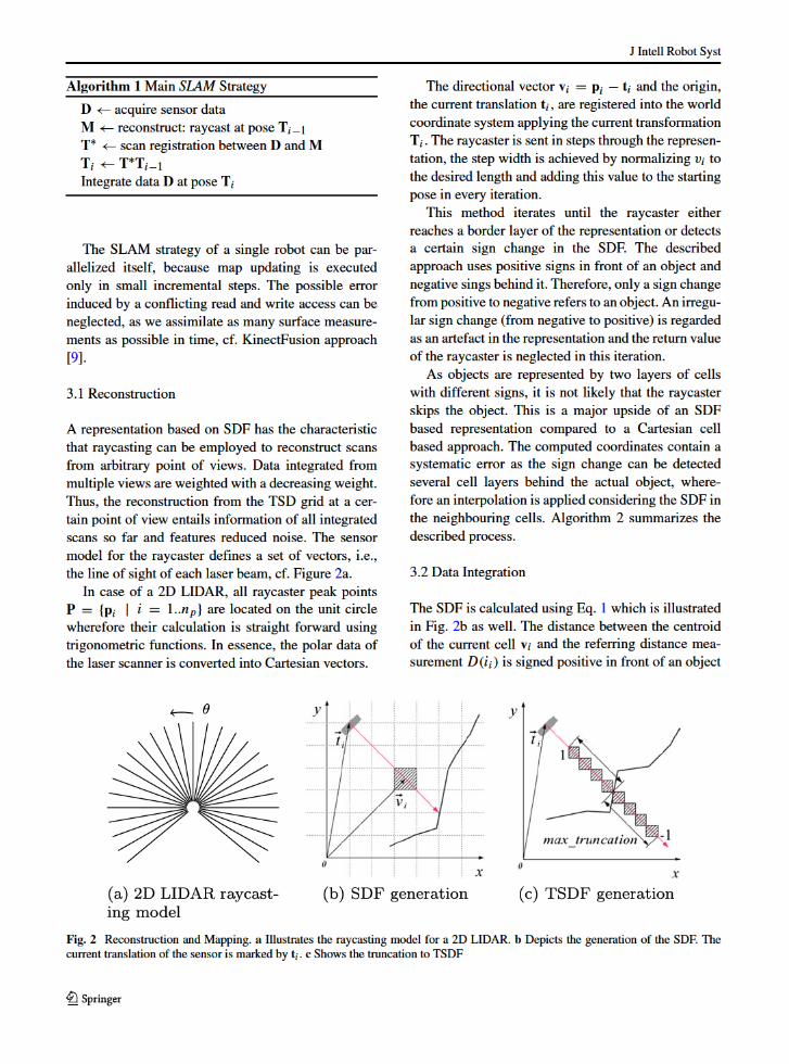
An iteration of our SLAM approach is triggered bynew sensor frames and consists of three steps. In thefirst step, the physical parameters of the input deviceare used to reconstruct a model M = {mi | i =1..nm} containing coordinates mi = (xi, yi)
T , whichis a virtual sensor frame generated through raycastingfrom the last known pose.
Step two uses this data as model for scan match-ing with the actual laser measurements, the sceneD = {di | i = 1..nd} containing coordinates di =(xi, yi)
T . We use the well known Iterative Clos-est Points (ICP) algorithm introduced by Zhang andZhengyou [17] and Chen and Medioni [5]. The sen-sor’s pose is denoted as 3×3 transformation matrixTi ,consisting of a translational vector t = (tx, ty)
T and arotational matrixR(α). Ti is updated with incrementalpose change T∗ from time step i − 1 to i:
Ti = T∗Ti−1,T∗ =⎛⎝
cos(α) sin(α) tx−sin(α) cos(α) ty
0 0 1
⎞⎠ .
The third step uses the current pose and sensordata to update the representation. The grid containsTruncated Signed Distances (TSD) as used in the wellknown KinectFusion approach [9]. We call this rep-resentation TSD grid in the remainder. Algorithm 1illustrates coarsely the whole approach.
Pose estimation of multiple robots has to be exe-cuted in parallel. Since the sensor data is matchedagainst the global map, parallel access is inevitable.Nevertheless, raycasting reconstruction applies onlyreading access wherefore synchronization usingmutexes is unnecessary.
J Intell Robot Syst
Algorithm 2 Raycasting based reconstruction
Calculate peak points pi
Calculate vi
Normalize vi to step lengtht∗i = Titiwhile (raycaster within bounds) do
if (sdfi−1 > 0 & sdfi < 0) thenInterpolate coordinatesReturn
end ifend while
or negative, behind it. This computation is depicted inFig. 2b.
sdfi = ‖ti − vi‖ − D(ii) (1)
In order to determine the referring laser beam, thecell centroids V = {vi | i = 1..nv} are back pro-jected with a specific sensor model. This computationcalculates the laser beam closest to the current cellcentroid vi , it is depicted in Eq. 3.
As these coordinates are in the world coordinatesystem, they need to be registered to the sensor coor-dinate system as follows:
V∗ = T−1i V (2)
The centroids v∗i = (v∗
ix, v∗iy) are assigned to laser
beams as follows:
αi = arctan(v∗iy
v∗ix
), (3)
ii = αi
r(4)
where αi is the beam’s polar angle, ii the assignedbeam index and r the sensor’s angular resolution.
In order to determine whether the back projectedcell centroid is visible by the sensor from the currentpose, the computed beam index is compared to thesensor bounds. These bounds refer to the maximal andminimal beam indices and are defined by the physicalparameters of the sensor model. If this index com-plies the comparison, the current SDF is computed,otherwise the algorithm continues with the next cellcentroid.
In order to prevent occlusions of objects, the SDF istruncated to a certain cell layer thickness, the so calledtruncation radius. This process is illustrated in Fig. 2c.
The output is stored in the cell using a weightedaverage. Algorithm 3 illustrates the approach.
Algorithm 3Map update
V∗ = T−1i V
Back project V∗for (all v∗
i V∗) do
Calculate beam index iiif (ii within bounds) then
sdfi = ∥∥ti − v∗i
∥∥ − D(ii)
Calculate weighted averageStore average and new weight
end ifend for
4 Multi-Robot Framework
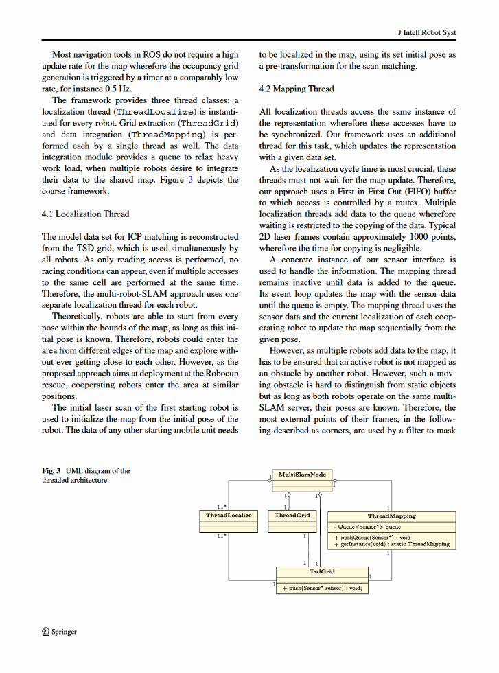
As the multi-SLAM framework uses a TSD based rep-resentation, it will be referred to as TSD SLAM inthe following. As described in the previous section, aniteration of the TSD SLAM approach consists mainlyof three steps: reconstruction, localization and dataintegration. Considering the usage of a Robot Oper-ating System (ROS)-based architecture, a fourth stepis necessary extracting a compatible representationout of the TSD grid. Many ROS nodes require anoccupancy grid as input.
Considering simultaneous multi-SLAM capabili-ties, these tasks have to be performed for every robot.However, as the current pose needs to be supplied witha fast and constant update rate in order to use it forpose and motion controllers, the localization should bedecoupled from other tasks. Modern CPUs consist ingeneral of multiple cores allowing parallel processingof data with a multi-threaded architecture.
To supply a fast pose update rate, a high prioritylocalization thread is started for each robot, which istriggered by new input data. Map building (data inte-gration) is executed asynchronously because it onlyneeds to be performed if the pose changes signif-icantly. The described strategy does not merge thegenerated maps of the cooperating robots, it uses theability of the framework, to update the map from a cer-tain pose. Therefore, every cooperating robot is ableto add new sensor data to the global shared map.
J Intell Robot Syst
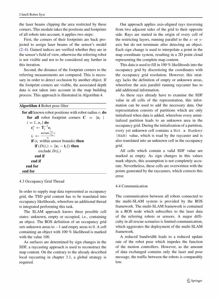
the laser beams clipping the area restricted by thesecorners. This module takes the positions and footprintsof all robots into account, it applies two steps:
First, the corners of their footprints are back pro-jected to assign laser beams of the sensor’s model(2–4). Gained indices are verified whether they are inthe sensor’s field of view, otherwise the referring robotis not visible and not to be considered any further inthis iteration.
Second, the distance of the footprint corners to thereferring measurements are compared. This is neces-sary in order to detect occlusion by another object. Ifthe footprint corners are visible, the associated depthdata is not taken into account in the map buildingprocess. This approach is illustrated in Algorithm 4.
Algorithm 4 Robot pose filter
for all known robot positions with robot radius ri dofor all robot footprint corners C = {ci |i = 1..nc} do
c∗i ← T−1
i ci
ii ← arctan(ciycix
)
riif (ii within sensor bounds) thenif (D(ii) > ‖ci − ti‖) thenexclude D(ii)
end ifend if
end forend for
4.3 Occupancy Grid Thread
In order to supply map data represented as occupancygrid, the TSD grid content has to be translated intooccupancy likelihoods, wherefore an additional threadis integrated performing this task.
The SLAM approach knows three possible cellstates: unknown, empty or occupied, i.e., containingan object. The ROS definition of an occupancy gridsets unknown areas to −1 and empty areas to 0. A cellcontaining an object with 100 % likelihood is markedwith the value 100.
As surfaces are determined by sign changes in theSDF, a raycasting approach is used to reconstruct themap content. On the contrary to the already describedlocal raycasting in chapter 3.1, a global strategy isrequired.
Our approach applies axis-aligned rays traversingfrom two adjacent sides of the grid to their oppositeside. Rays are started in the origin of every cell ofthe restricting layers, running parallel to the x- or y-axis but do not terminate after detecting an object.Each sign change is used to interpolate a point in themap coordinate system, resulting in a 2D point cloudrepresenting the complete map content.
This data is used to fill in 100 % likelihoods into theoccupancy grid by discretizing the coordinates withthe occupancy grid resolution. However, this strat-egy lacks the definition of empty or unknown areas,wherefore the axis parallel running raycaster has toadd additional information.
As these rays already have to examine the SDFvalue in all cells of the representation, this infor-mation can be used to add the necessary data. Ourrepresentation consists of partitions which are onlyinitialized when data is added, wherefore every unini-tialized partition leads to an unknown area in theoccupancy grid. During the initialization of a partition,every yet unknown cell contains a Not a Number(NaN) value, which is read by the raycaster and isalso translated into an unknown cell in the occupancygrid.
All cells which contain a valid SDF value aremarked as empty. As sign changes in this valuesmark objects, this assumption is not completely accu-rate. Nevertheless, these cells are overwritten with thepoints generated by the raycasters, which corrects thiserror.
4.4 Communication
The communication between all robots connected tothe multi-SLAM system is provided by the ROSframework. The multi-SLAM framework is containedin a ROS node which subscribes to the laser dataof the referring robots or sensors. A major diffi-culty in all rescue scenarios is limited communication,which aggravates the deployment of the multi-SLAMframework.
A reduced bandwidth leads to a reduced updaterate of the robot pose which impedes the functionof the motion controllers. However, as the amountof data exchanged contains only the laser and posemessage, the traffic between the robots is comparablylow.
J Intell Robot Syst
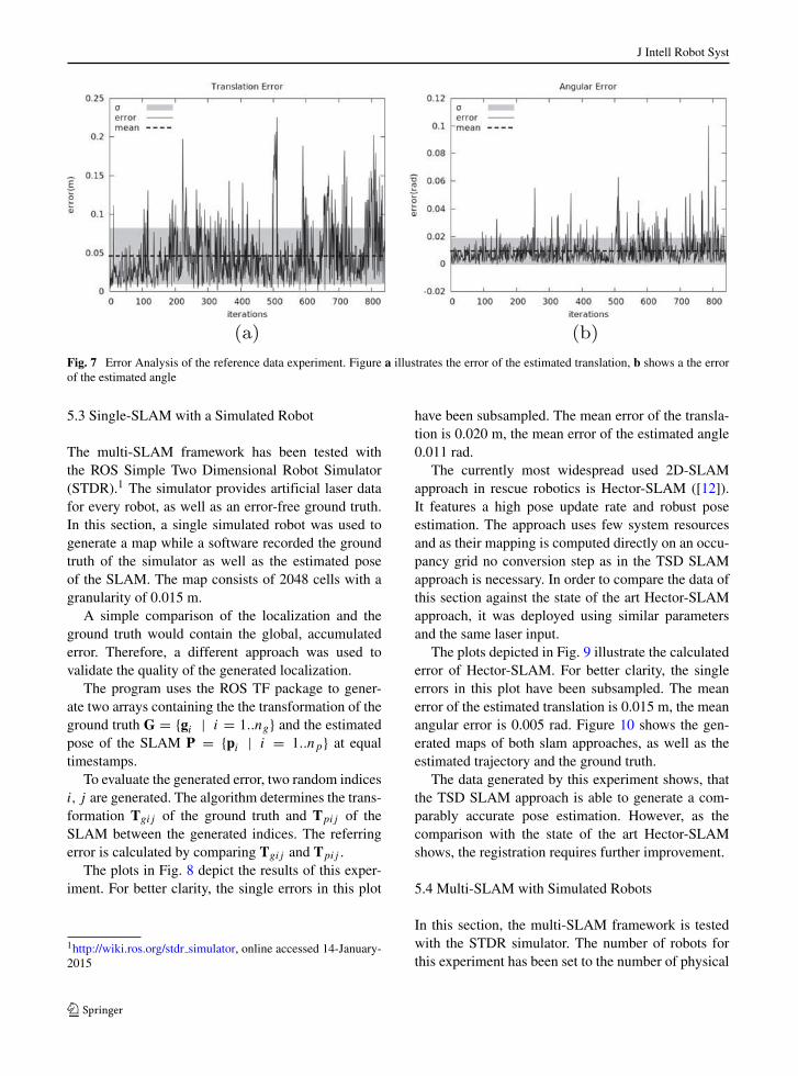
Fig. 7 Error Analysis of the reference data experiment. Figure a illustrates the error of the estimated translation, b shows a the errorof the estimated angle
5.3 Single-SLAM with a Simulated Robot
The multi-SLAM framework has been tested withthe ROS Simple Two Dimensional Robot Simulator(STDR).1 The simulator provides artificial laser datafor every robot, as well as an error-free ground truth.In this section, a single simulated robot was used togenerate a map while a software recorded the groundtruth of the simulator as well as the estimated poseof the SLAM. The map consists of 2048 cells with agranularity of 0.015 m.
A simple comparison of the localization and theground truth would contain the global, accumulatederror. Therefore, a different approach was used tovalidate the quality of the generated localization.
The program uses the ROS TF package to gener-ate two arrays containing the the transformation of theground truth G = {gi | i = 1..ng} and the estimatedpose of the SLAM P = {pi | i = 1..np} at equaltimestamps.
To evaluate the generated error, two random indicesi, j are generated. The algorithm determines the trans-formation Tgij of the ground truth and Tpij of theSLAM between the generated indices. The referringerror is calculated by comparing Tgij and Tpij .
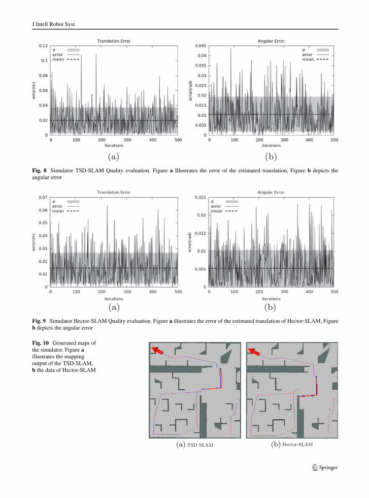
The plots in Fig. 8 depict the results of this exper-iment. For better clarity, the single errors in this plot
1http://wiki.ros.org/stdr simulator, online accessed 14-January-2015
have been subsampled. The mean error of the transla-tion is 0.020 m, the mean error of the estimated angle0.011 rad.
The currently most widespread used 2D-SLAMapproach in rescue robotics is Hector-SLAM ([12]).It features a high pose update rate and robust poseestimation. The approach uses few system resourcesand as their mapping is computed directly on an occu-pancy grid no conversion step as in the TSD SLAMapproach is necessary. In order to compare the data ofthis section against the state of the art Hector-SLAMapproach, it was deployed using similar parametersand the same laser input.
The plots depicted in Fig. 9 illustrate the calculatederror of Hector-SLAM. For better clarity, the singleerrors in this plot have been subsampled. The meanerror of the estimated translation is 0.015 m, the meanangular error is 0.005 rad. Figure 10 shows the gen-erated maps of both slam approaches, as well as theestimated trajectory and the ground truth.
The data generated by this experiment shows, thatthe TSD SLAM approach is able to generate a com-parably accurate pose estimation. However, as thecomparison with the state of the art Hector-SLAMshows, the registration requires further improvement.
5.4 Multi-SLAM with Simulated Robots
In this section, the multi-SLAM framework is testedwith the STDR simulator. The number of robots forthis experiment has been set to the number of physical
J Intell Robot Syst
Fig. 8 Simulator TSD-SLAM Quality evaluation. Figure a Illustrates the error of the estimated translation, Figure b depicts theangular error
Fig. 9 Simulator Hector-SLAM Quality evaluation. Figure a illustrates the error of the estimated translation of Hector-SLAM, Figureb depicts the angular error
Fig. 10 Generated maps ofthe simulator. Figure aillustrates the mappingoutput of the TSD-SLAM,b the data of Hector-SLAM

J Intell Robot Syst
Fig. 11 Phases of the simulated multi-SLAM. Chronological order from t0 to t2
processor cores, wherefore hardware resources areused at high capacity. The map dimensions are thesame as in the first experiment (Section 5.1).
The four simulated units start at the same time andexplore a labyrinth, building a map of the surrounding.The experiment was documented taking screenshotsof the map containing the ground truth of the simulatorand the estimated trajectory. Figures 11 and 12 showthe process and the results of the simulated experi-ment. The blue line marks the ground truth, and thered line the estimated trajectory.
5.5 Multi SLAM of a Building Floor
This experiment addresses the Robocup Rescue sce-nario, the multi-SLAM is being developed for a teamof two cooperating robots (Fig. 13) exploring anindoor area. The robot “Simon” explores one part ofthe building, and robot “Georg” another. Both areequipped with the same LIDAR, a Hokuyo UTM30-LX. In order to validate the limited drifting error of
our framework, both trajectories contain loops. Themapped building is the same as in Section 5.1.
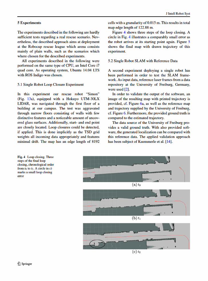
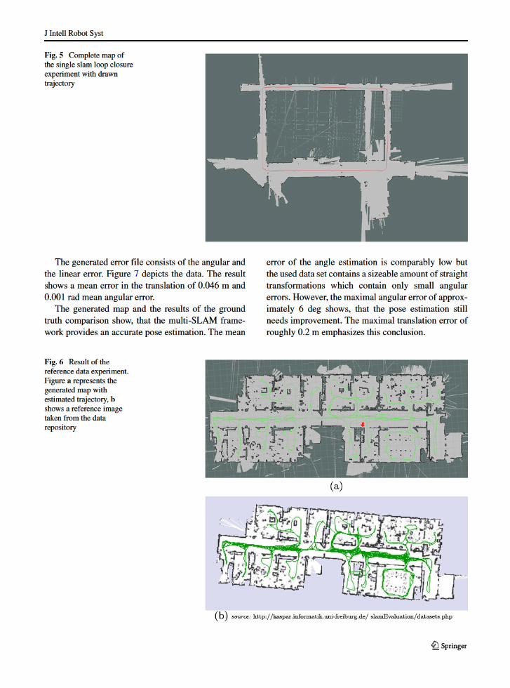
Figure 14 illustrates both robots closing their loopssimultaneously as they arrive at the same time at theirstarting points. These images depict the limited drift ofour framework as only comparably small errors occur.The final, simultaneously built map is displayed inFig. 15.
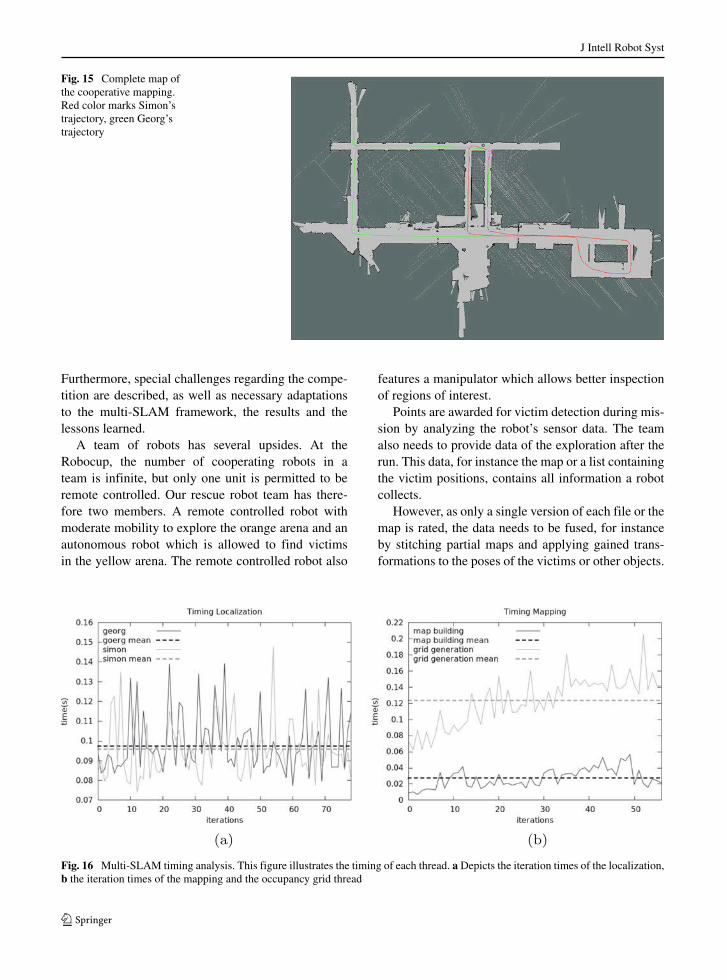
During the multi-SLAM experiment, the timing ofeach thread has been logged in order to analyse thisdata. Figure 16 consists of plots depicting the timing.For better clarity, the single iteration times have beensub sampled. The localization threads show similariteration times both at a mean of approximately 11 hz.
The mapping thread consumes a mean of 0.027 s.The iteration times of the occupancy grid are increas-ing as more data is added to the map, the referringmean is at 0.12 s. This process is obviously the mosttime consuming and gets more expensive as the map isfilled. However, since the generation of the occupancygrid is only required occasional, it can be neglected.
Fig. 12 Multi-SLAMsimulation result.Comparison of thereconstructed map (a) andthe original model used bythe simulator (b)
J Intell Robot Syst
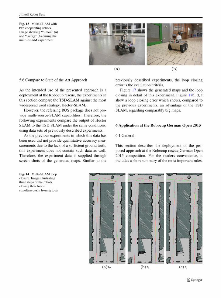
Fig. 13 Multi-SLAM withtwo cooperating robots.Image showing “Simon” (a)and “Georg” (b) during themulti-SLAM experiment
5.6 Compare to State of the Art Approach
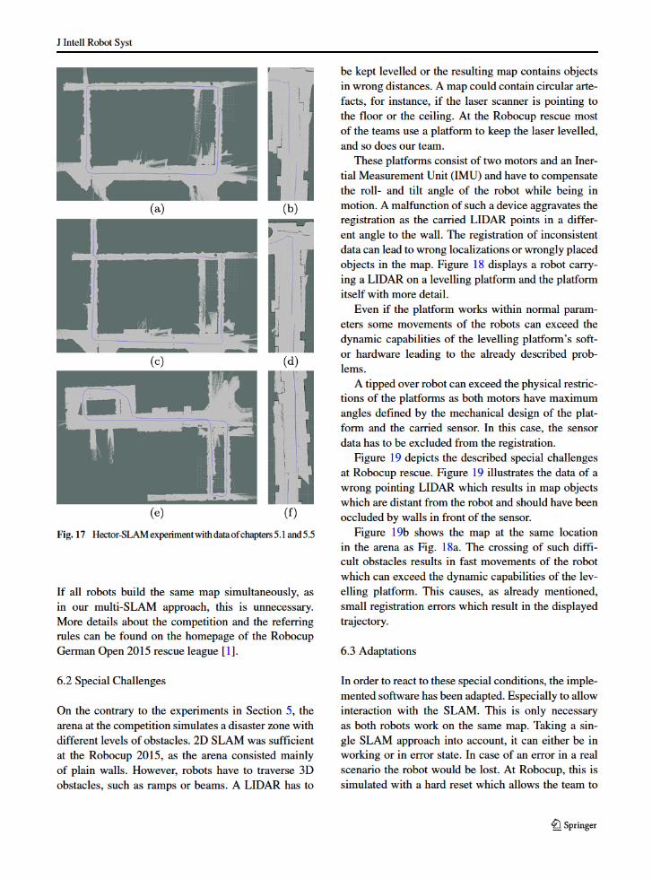
As the intended use of the presented approach is adeployment at the Robocup rescue, the experiments inthis section compare the TSD-SLAM against the mostwidespread used strategy, Hector-SLAM.
However, the referring ROS package does not pro-vide multi-source-SLAM capabilities. Therefore, thefollowing experiments compare the output of HectorSLAM to the TSD SLAM under the same conditions,using data sets of previously described experiments.
As the previous experiments in which this data hasbeen used did not provide quantitative accuracy mea-surements due to the lack of a sufficient ground truth,this experiment does not contain such data as well.Therefore, the experiment data is supplied throughscreen shots of the generated maps. Similar to the
previously described experiments, the loop closingerror is the evaluation criteria,
Figure 17 shows the generated maps and the loopclosing in detail of this experiment. Figure 17b, d, fshow a loop closing error which shows, compared tothe previous experiments, an advantage of the TSDSLAM, regarding comparably big maps.
6 Application at the Robocup German Open 2015
6.1 General
This section describes the deployment of the pro-posed approach at the Robocup rescue German Open2015 competition. For the readers convenience, itincludes a short summary of the most important rules.
Fig. 14 Multi-SLAM loopclosure. Image illustratingthree steps of the robotsclosing their loopssimultaneously from t0 to t2
J Intell Robot Syst
Fig. 15 Complete map ofthe cooperative mapping.Red color marks Simon’strajectory, green Georg’strajectory
Furthermore, special challenges regarding the compe-tition are described, as well as necessary adaptationsto the multi-SLAM framework, the results and thelessons learned.
A team of robots has several upsides. At theRobocup, the number of cooperating robots in ateam is infinite, but only one unit is permitted to beremote controlled. Our rescue robot team has there-fore two members. A remote controlled robot withmoderate mobility to explore the orange arena and anautonomous robot which is allowed to find victimsin the yellow arena. The remote controlled robot also
features a manipulator which allows better inspectionof regions of interest.
Points are awarded for victim detection during mis-sion by analyzing the robot’s sensor data. The teamalso needs to provide data of the exploration after therun. This data, for instance the map or a list containingthe victim positions, contains all information a robotcollects.
However, as only a single version of each file or themap is rated, the data needs to be fused, for instanceby stitching partial maps and applying gained trans-formations to the poses of the victims or other objects.
Fig. 16 Multi-SLAM timing analysis. This figure illustrates the timing of each thread. aDepicts the iteration times of the localization,b the iteration times of the mapping and the occupancy grid thread
J Intell Robot Syst
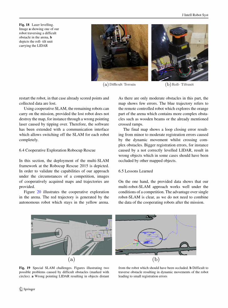
Fig. 18 Laser levelling.Image a showing one of ourrobot traversing a difficultobstacle in the arena, bdepicts the roll- tilt unitcarrying the LIDAR
restart the robot, in that case already scored points andcollected data are lost.
Using cooperative SLAM, the remaining robots cancarry on the mission, provided the lost robot does notdestroy the map, for instance through a wrong pointinglaser caused by tipping over. Therefore, the softwarehas been extended with a communication interfacewhich allows switching off the SLAM for each robotcompletely.
6.4 Cooperative Exploration Robocup Rescue
In this section, the deployment of the multi-SLAMframework at the Robocup Rescue 2015 is depicted.In order to validate the capabilities of our approachunder the circumstances of a competition, imagesof cooperatively acquired maps and trajectories areprovided.
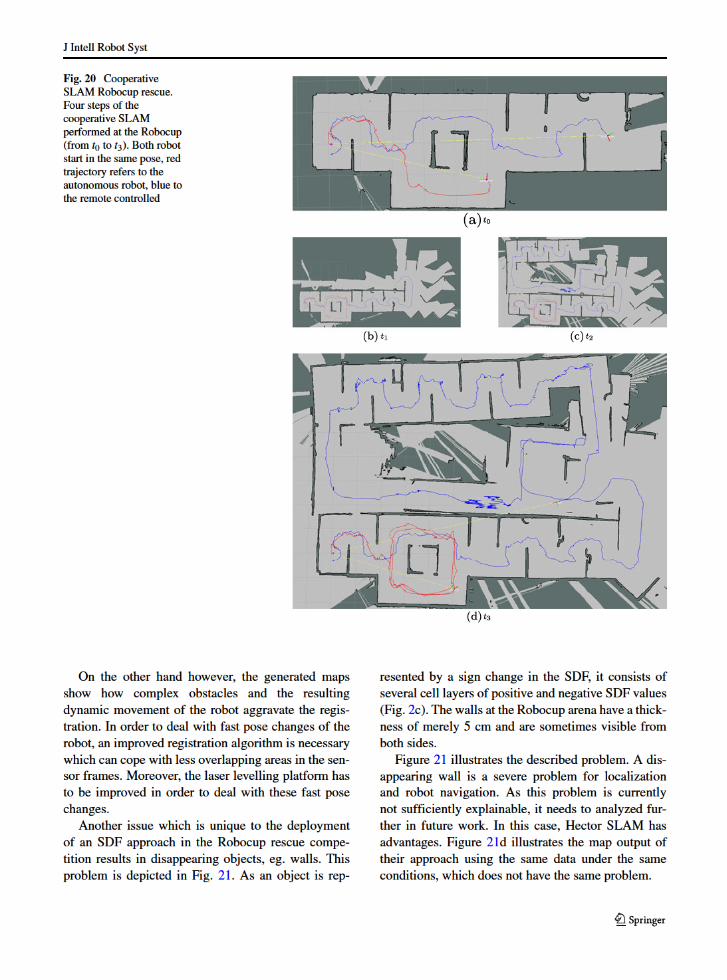
Figure 20 illustrates the cooperative explorationin the arena. The red trajectory is generated by theautonomous robot which stays in the yellow arena.
As there are only moderate obstacles in this part, themap shows few errors. The blue trajectory refers tothe remote controlled robot which explores the orangepart of the arena which contains more complex obsta-cles such as wooden beams or the already mentionedcrossed ramps.
The final map shows a loop closing error result-ing from minor to moderate registration errors causedby the dynamic movement whilst crossing com-plex obstacles. Bigger registration errors, for instancecaused by a not correctly levelled LIDAR, result inwrong objects which in some cases should have beenoccluded by other mapped objects.
6.5 Lessons Learned
On the one hand, the provided data shows that ourmulti-robot-SLAM approach works well under theconditions of a competition. The advantage over singlerobot-SLAM is clear, as we do not need to combinethe data of the cooperating robots after the mission.
Fig. 19 Special SLAM challenges. Figures illustrating twopossible problems caused by difficult obstacles (marked withcircles). a Wrong pointing LIDAR resulting in objects distant
from the robot which should have been occluded. b Difficult totraverse obstacle resulting in dynamic movements of the robotleading to small registration errors
J Intell Robot Syst
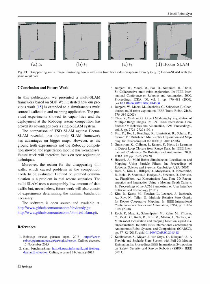
Fig. 21 Disappearing walls. Image illustrating how a wall seen from both sides disappears from t0 to t2. c) Hector-SLAM with thesame input data
7 Conclusion and Future Work
In this publication, we presented a multi-SLAMframework based on SDF. We illustrated how our pre-vious work [15] is extended to a simultaneous multisource localization and mapping application. The pro-vided experiments showed its capabilities and thedeployment at the Robocup rescue competition hasproven its advantages over a single-SLAM system.
The comparison of TSD SLAM against Hector-SLAM revealed, that the multi-SLAM frameworkhas advantages on bigger maps. However, as theground truth experiments and the Robocup competi-tion showed, the registration module has weaknesses.Future work will therefore focus on new registrationtechniques.
Moreover, the reason for the disappearing thinwalls, which caused problems in the competition,needs to be evaluated. Limited or jammed commu-nication is a problem in real rescue scenarios. Themulti-SLAM uses a comparably low amount of datatraffic but, nevertheless, future work will also consistof experiments determining the minimal bandwidthnecessary.
The software is open source and available at:http://www.github.com/autonohm/obviously.githttp://www.github.com/autonohm/ohm tsd slam.git.
References
1. Robocup rescue german open 2015. https://www.robocupgermanopen.de/en/major/rescue. Online; accessed15-November-2015
2. slam benchmarking. http://kaspar.informatik.uni-freiburg.de/slamEvaluation. Online; accessed 14-January-2015
3. Burgard, W., Moors, M., Fox, D., Simmons, R., Thrun,S.: Collaborative multi-robot exploration. In: IEEE Inter-national Conference on Robotics and Automation, 2000.Proceedings. ICRA ’00, vol. 1, pp. 476–481 (2000).doi:10.1109/ROBOT.2000.844100
4. Burgard, W., Moors, M., Stachniss, C., Schneider, F.: Coor-dinated multi-robot exploration. IEEE Trans. Robot. 21(3),376–386 (2005)
5. Chen, Y., Medioni, G.: Object Modeling by Registration ofMultiple Range Images. In: 1991 IEEE International Con-ference On Robotics and Automation, 1991. Proceedings.,vol. 3, pp. 2724–2729 (1991)
6. Fox, D., Ko, J., Konolige, K., Limketkai, B., Schulz, D.,Stewart, B.: Distributed Multi-Robot Exploration and Map-ping. In: Proceedings of the IEEE, p. 2006 (2006)
7. Granstrom, K., Callmer, J., Ramos, F., Nieto, J.: Learningto Detect Loop Closure from Range Data. In: IEEE Inter-national Conference On Robotics and Automation, 2009.ICRA ’09, pp. 15–22 (2009)
8. Howard, A.: Multi-Robot Simultaneous Localization andMapping Using Particle Filters. In: Proceedings ofRobotics: Science and Systems, Cambridge, USA (2005)
9. Izadi, S., Kim, D., Hilliges, O., Molyneaux, D., Newcombe,R., Kohli, P., Shotton, J., Hodges, S., Freeman, D., Davison,A., Fitzgibbon, A.: Kinectfusion: Real-Time 3D Recon-struction and Interaction Using a Moving Depth Camera.In: Proceedings of the ACM Symposium on User InterfaceSoftware and Technology (2011)
10. Kim, B., Kaess, M., Fletcher, L., Leonard, J., Bachrach,A., Roy, N., Teller, S.: Multiple Relative Pose Graphsfor Robust Cooperative Mapping. In: IEEE InternationalConference on Robotics and Automation, ICRA, pp. 3185–3192 (2010)
11. Koch, P., May, S., Schmidpeter, M., Kuhn, M., Pfitzner,C., Merkl, C., Koch, R., Fees, M., Martin, J., Nuchter, A.:Multi-robot localization and mapping based on signed dis-tance functions. In: 2015 IEEE International Conference onAutonomous Robot Systems and Competitions (ICARSC),pp. 77–82 (2015). doi:10.1109/ICARSC.2015.18
12. Kohlbrecher, S., Meyer, J., von Stryk, O., Klingauf, U.: AFlexible and Scalable Slam System with Full 3D MotionEstimation. In: Proceedings IEEE International Symposiumon Safety, Security and Rescue Robotics (SSRR), IEEE(2011)
J Intell Robot Syst
13. Konolige, K., Fox, D., Ortiz, C., Agno, A., Eriksen, M.,Limketkai, B., Ko, J., Morisset, B., Schulz, D., Stewart,B., Vincent, R.: Centibots: Very Large Scale DistributedRobotic Teams. In: Khatib, M.HA.Jr., O. (ed.) ISER,Springer Tracts in Advanced Robotics, vol. 21, pp. 131–140. Springer (2004)
14. Kummerle, R., Steder, B., Dornhege, C., Ruhnke, M.,Grisetti, G., Stachniss, C., Kleiner, A.: On measuring theaccuracy of slam algorithms. Auton. Robot. 27(4), 387–407(2009)
15. May, S., Koch, P., Koch, R., Merkl, C., Pfitzner, C.,Nuchter, A.: A Generalized 2D and 3D Multi-Sensor DataIntegration Approach Based on Signed Distance Func-tions for Multi-Modal Robotic Mapping. In: VMV 2014:Vision, Modeling & Visualization, Darmstadt, Germany,2014. Proceedings, pp. 95–102 (2014)
16. Osher, S., Fedkiw, R.: Level Set Methods and DynamicImplicit Surfaces (Applied Mathematical Sciences). 2003rdedn. Springer (2002)
17. Zhang, Z.: Iterative point matching for registration of free-form curves and surfaces. Int. J. Comput. Vis. 13(2), 119–152 (1994)
Philipp Koch was born in Gottingen, Germany, in 1982. Hegraduated with a Bachelor of Engineering at the NurembergInstitute of Technology (NIT) in the field of electrical engineer-ing and information technologies in 2012. In the year 2014, hereceived the degree Master of Science in the field of 2D/3Dreconstruction and SLAM, also at the NIT. Since 2014, heworks as a research assistant at the NIT in the field of mobilerobotics, focussing on autonomous systems in the field of indus-trial intralogistic robots and rescue robotics. His research workincludes 2D/3D reconstruction, SLAM and traversability.
Stefan May received a diploma (electrical engineering) in 2000and a Masters degree (software engineering) in 2004 from theGeorg Simon Ohm University of Applied Sciences in Nurem-berg. In 2009 he received his PhD in computer vision fromthe University in Osnabrueck. Between 2002 and 2009 he wasworking in the context of test systems for automotive electronicsand 3D vision for mobile robotics at Audi and Fraunhofer IAISin Germany and INRIA in France. Since 2010, he is professorfor Automation andMechatronics at the Technische HochschuleNuremberg Georg Simon Ohm. He is head of the Laboratory forMobile Robotics focusing academic and industrial applications.His main research interests include sensors and data processingfor 3D perception of mobile robots.
Michael Schmidpeter was born in 1989. He received hisBachelor of Engineering degree in electrical engineering andinformation technologies in 2013 at the Nuremberg Institute ofTechnology (NIT). In 2015, he graduated with a Master of Sci-ence in the field of autonomous robots, also at the NIT. Since2015 he works as a research assistant at the Nuremberg Campusof Technology. His main focus lies on multi-robot navigation.
Markus Kuhn was born 1992 in Furth, Germany. In 2014, hereceived his Bachelor of Engineering degree in computer sci-ence at the Corporate State University of Baden-Wuerttembergin Friedrichshafen, Germany. He graduated at the NurembergInstitute of Technology (NIT) with a Master of Science degreein 2016 which focused on applied robotics research. In particu-lar, he studies approaches for localization and mapping as wellas software architectures for drone autonomy.
Christian Pfitzner was born in 1987 in Nuremberg, Germany.He received the Bachelor of Engineering degree in electricalengineering and information technologies at the NurembergInstitute of Technology (NIT), Germany, in 2011. For the Mas-ter of Science degree he studied exploration strategies formobile robotics in rescue environment, also at the NIT. Since2014 he is a PhD student at the Graduate School of LiveSciences at the Julius-Maximilians University Wuerzburg, Ger-many. Since 2014 he works as a research assistant at the Nurem-berg Campus of Technology in the field of mobile robotics and3d vision for medical applications. Furthermore, he is a lecturerfor the field of mobile robotics at the NIT and the ROS Sum-mer School in Aachen, Germany. Website: christian-pfitzner.de/research.
ChristianMerklwas born in 1983 in Nuremberg, Germany. Hereceived the Bachelor of Engineering degree in electrical engi-neering and information technologies at the Nuremberg Instituteof Technology (NIT), Germany, in 2012. For the Master ofScience degree he studied detection of the human body usingcontactless sensor systems, also at the NIT. Since 2014 he worksas a research assistant at the Nuremberg Campus of Technologyin the field of HMI. Furthermore, he is a temporary lecturer forcomputer science.
Rainer Koch received his diploma (power engineering and sys-tem control) in 2007 and his Master‘s degree (electronical andmechatronical systems) in 2010 from the Georg-Simon OhmUniversity of Applied Science in Nuremberg. Between 2007and 20011 he was working as a research assistant at the Institutefor Power Electronics ELSYS at the Georg-Simon Ohm Univer-sity of Applied Science. Since 2011 he is a PhD student at theautonomous robotics team at the Nuremberg Institute of Tech-nology Georg-Simon Ohm. His research interests include sensorand data processing for 2D and 3D perception of mobile robots.
Martin Fees was born 1991 in Erlangen, Germany. He receivedthe Bachelor of Engineering degree in mechanical engineering2014 at the Nuremberg Institute of Technology (NIT), Ger-many. Since 2014 he is receiving his Master of Science degreeby developing an inspection and manipulation arm for mobilerescue robots at the NIT.
J Intell Robot Syst
Jon Martin was born in Bilbao, Spain, in 1989. He first gradu-ated as a technical industrial engineer, specialized in Electronicsat the University of the Basque Country in 2011. Furthermore,he received a Diploma in Electronics and Automatization inalso at the University of the Basque Country in 2014. He didhis Thesis as an exchange student at the Nuremberg Institute ofTechnology, it included navigation and path-path planning of amobile robot in an industrial environment. Since then he worksas a research assistant at the NIT. His main focus lies on indoorservice robotics and multi robot communication.
Daniel Ammon was born in Nuremberg, Germany, in 1988.He graduated with a Bachelor of Engineering at the Nurem-berg Institute of Technology (NIT) in the field of mechatronicswith priority on automation, in 2015. Since then, he studies asa master’s degree candidate at the Nuremberg Institute of Tech-nology in the field of mobile rescue and service robotics. Hismain focus lies on localization algorithms for indoor servicerobotics. His actual work includes the development of a particlefilter algorithm for indoor localization and improvements on 2DSLAM algorithms.
Andreas Nuchter is professor of Computer Science (telem-atics) at University of Wurzburg. Before summer 2013 hewas affiliated with the Automation group at Jacobs UniversityBremen, with the University of Osnabruck, and with the Fraun-hofer Institute for Autonomous Intelligent Systems (AIS, SanktAugustin). Prof. Nuchter holds a PhD and a diploma degree inComputer Science from the University of Bonn. His diplomathesis was awarded by the German society of informatics (GI)and his dissertation was shortlisted for the EURON PhD award.Prof. Nuchter works on telematics systems for robotics andautomation, 3D vision and laser scanning, cognitive systemsand artificial intelligence.