Embed Size (px)
Citation preview
Multi-Step Bid
No. GPA-048-09
PERFORMANCE MANAGEMENT CONTRACT
FOR THE
GUAM POWER AUTHORITY FUEL FARM BULK STORAGE FACILITY AND PIPELINES
Volume III
Technical Description
JULY 2009
- DRAFT AS OF JUNE 9, 2009 -
TABLE OF CONTENTS
Section Description Page
i
1. Introduction ........................................................................................................................... 1 1.1. Purpose ................................................................................................................................... 1 1.2. Assumptions and Scope......................................................................................................... 1 1.3. Facility General Description................................................................................................. 1 1.4. History .................................................................................................................................... 2 1.5. Tank Repair and Upgrading Project ................................................................................... 3 1.5.1. Tank Inspections and Repairs.............................................................................................. 3 1.5.1.1. Tank Bottom Repairs ............................................................................................................ 4 1.5.1.2. Tank Shell Repairs ................................................................................................................ 4 1.5.1.3. Tank Roof Repairs ................................................................................................................ 5 1.5.2. Cathodic Protection System.................................................................................................. 6 1.5.3. Leak Detection System.......................................................................................................... 6 1.5.4. Hydrostatic Testing ............................................................................................................... 6 1.5.5. Oil-Water Separator Repairs ............................................................................................... 6 1.5.6. Pipeline Repairs..................................................................................................................... 7 2. Site Description and Characteristics ................................................................................... 8 2.1. General Location ................................................................................................................... 8 2.2. Site Location and Description .............................................................................................. 8 2.3. Community............................................................................................................................. 8 2.4. Site Map.................................................................................................................................. 9 2.5. Site Infrastructure / Utilities................................................................................................. 9 2.5.1. Domestic Water ..................................................................................................................... 9 2.5.2. Electrical Power................................................................................................................... 10 2.5.3. Station Lighting ................................................................................................................... 10 2.5.4. Communications System..................................................................................................... 10 2.6. Incident Mitigation Capabilities ........................................................................................ 10 2.7. On-site Safety Equipment................................................................................................... 10 3. Fuel Bulk Storage Facility and Pipelines Technical Description .................................... 11 3.1. Storage Tanks and Related Systems .................................................................................. 11 3.1.1. Bulk Residual Fuel Oil (RFO) Storage.............................................................................. 11 3.1.2. Diesel Oil Storage ................................................................................................................ 12 3.1.3. Fuel Oil Transfer Pumps .................................................................................................... 12 3.2. Pipeline System .................................................................................................................... 13 3.2.1. Fuel Supply Pipeline System............................................................................................... 13 3.2.2. Condition Assessment ......................................................................................................... 13 3.3. Oil Quality Sampling and Testing...................................................................................... 13 4. Operations and Maintenance ............................................................................................. 14 4.1. Product Movement .............................................................................................................. 14 4.2. Operations and Maintenance Procedures ......................................................................... 14 4.3. Central Support Services .................................................................................................... 14 4.3.1. Central Maintenance Capabilities ..................................................................................... 14 4.3.2. Central Warehousing Capabilities..................................................................................... 15 4.3.3. Generation Administration Capabilities ........................................................................... 15 4.3.4. Engineering Division Capabilities...................................................................................... 15 4.3.5. Computerized Maintenance Management System........................................................... 15
TABLE OF CONTENTS
Section Description Page
ii
4.4. Plant Organization .............................................................................................................. 16 4.5. Capital and O&M Performance Improvement Projects ................................................. 16 4.6. Historic Spending Patterns................................................................................................ 21 4.7. Fuel Oil Pipeline Repairs and Inspections ....................................................................... 22 5. Facility Documentation Summary ..................................................................................... 24
Performance Management Contract Technical Description Fuel Bulk Storage Facility and Pipelines July 2009
1
1. Introduction 1.1. Purpose The purpose of this Technical Description is to provide technical information about the Fuel Farm Bulk Storage Facility and Pipelines to prospective proponents of the Performance Management Contract (PMC). This work is in conjunction with the Volume I Commercial Terms and Conditions, Volume II Technical and Functional Requirements, Volume IV Proposal Scoring Mechanism, and Volume V Appendices documents. This document provides information on the facility’s design, historical performance, operation, maintenance activities, future maintenance, capital requirements and condition assessment. The technical assessment of the Fuel Farm Bulk Storage Facility and Pipelines rely upon the input from experienced and knowledgeable plant, corporate and support personnel. The information contained in this Technical Review is the Guam Power Authority’s best effort at organizing, documenting and describing in their best words the overall condition of the facility equipment. All efforts have been taken to represent the status of the plant as accurately as possible to the prospective proponents. However, although every effort has been taken to represent the facility’s condition in a fair manner, not every item or actual condition of some equipment can be represented in this document. 1.2. Assumptions and Scope The review of the description, history and condition of the facility and its major equipment and systems was accomplished by performing physical inspections, reviewing documentation and conducting interviews with key plant and support personnel. The review included but was not limited to an assessment of the facility’s design and layout, capacity, system redundancy and equipment operations and maintenance (O&M) history. The historical documentation of equipment and systems reviews was not intended to be all inclusive, but rather to provide a reasonable perspective of the operating and maintenance history of the facility. The technical review is intended to be a factual description of the facility and refrains from offering conjecture or opinion, except where clearly identified. It is assumed that prospective proponents of this PMC will conduct their own verifying due diligence effort. 1.3. Facility General Description The Fuel Farm Bulk Storage Facility is wholly owned by the Guam Power Authority and operated and managed by its Contractor Peterra. GPA completed construction and commissioned Fuel Farm Bulk Storage Facility in 1976. The tanks and associated infrastructure were completed in 1976 by the United States Military and resides on compacted coral limestone fill with no previous history of hydrocarbon contamination. The tanks have been in service continually since construction was completed except for a period of time while the facility was transferred from military to civilian control.
Performance Management Contract Technical Description Fuel Bulk Storage Facility and Pipelines July 2009
2
Guam Power Authority (GPA) owns two bulk fuel storage tanks, 1935 and 1934, located at the GPA Fuel Farm Bulk Storage Facility in the Municipality of Piti between the Atlantis Submarine pier and the former Navy Power unit on the Piti Channel. These tanks are used to supply fuel to the Cabras Power Plants (including Marianas Electric Company Piti Units 8&9) located adjacent to the Piti tank farm, and the Tanguisson Power Plant located north of Tumon. The Tanguisson power plant is supplied by an 8-inch fuel line approximately 18 miles in length. The bulk storage fuel tanks originally did not have a Cathodic Protection System or a Leak Detection System in place. New Cathodic Protection and Leak Detection Systems installed for both tanks under the contract by the Tank 1935 Repair Contractor was completed in 2007. GPA has contracted the operation of the two-tank facility to Peterra Inc. The operations at the site include the storage of fuel oil, transfer of fuel oil into and out of the facility, and the processing of oily water. The facility receives up to approximately 3,000,000 barrels of fuel oil annually on tankers berthing at the PAG petroleum dock managed and operated by Shell Oil Guam. The type of fuel stored in these two tanks is Fuel Oil #6, or Bunker Fuel C. Fuel Oil #6 is a mixture of petroleum distillate hydrocarbons and has a boiling point greater than 400 degrees Fahrenheit. This fuel is commonly broken into two categories depending on the relative levels of sulfur contained in the fuel. High sulfur fuel, also known as sour fuel, is more corrosive and often has increased sulfur levels in stack emissions. The second type of fuel is low sulfur fuel also known as sweet fuel. Both of these fuels are used at the Power Plants. Previously both of these fuels were mixed between the two fuel storage tanks on site. This practice was stopped some years before and Tank 1934 is now used to store the low sulfur fuel. The oil-water separator (OWS) consists of a partially buried cast-in-place concrete tank with three interior sections. The wood and tin cover is used to keep out rain and other objects out of the containment and was recently (?) replaced by the tank repair contractor. The OWS system is connected to each bulk storage tank with a 3” or 4” discharge line. There was also a collection sump on the berm by the entry road for truck discharge of waste oil to the OWS. The Fuel Pipelines
1.4. History The Fuel Farm Bulk Storage Facility was designed and built for bulk fuel storage and centralize the distribution of fuel to support the baseload plants operation for power generation in order to meet the electric power utility needs of the island. The modernization of the Fuel farm Facility will be one of the challenges to the PMC. The PMC will be required to improve the operation and maintenance activities to allow the equipment to evolve toward an operation fully supportive GPA requirements. Improvements in the operations and maintenance organizations serve to achieve the new operating model. GPA has spent a considerable amount of money in recent years to maintain conformance with the USEPA and US Coast Guard requirements. The facility was upgraded in 2007 and currently meets Federal and Local regulatory standards. Both Tank 1934 and Tank 1935 have undergone needed condition assessment of the tank sections. Portions of the floor plates and other internal structures were replaced to improve tank system integrity. New pipelines were installed to improve flexibility in fuel transfer operations.
Performance Management Contract Technical Description Fuel Bulk Storage Facility and Pipelines July 2009
3
1.5. Tank Repair and Upgrading Project These tanks have not been drained and inspected prior to the commencement of this project so a base line of corrosion cannot be established. In addition, no construction records or record drawings for the tanks could be located. In February 2001 the United States Environmental Protection Agency (USEPA) Region IX issued a Unilateral Administrative Order for Piti Tank Farm to GPA to “perform abatement activities necessary to address conditions that may present an imminent and substantial endangerment”. These abatement activities “require integrity inspections, maintenance, installation of leak detection and repair of cathodic protection.” Due to continued operations at GPA’s Cabras and Tanguisson Power Plants, one tank remained in service at all times. Winzler & Kelly Consulting Engineers had been retained to prepare the contract documents for tank cleaning and repairs, perform the tank inspection and repair reports. PSC Industrial Services Group (Long Beach, California) was the Contractor retained by GPA to drain and clean both tanks. International Bridge Corporation (IBC) was awarded the contract to repair Tank 1935, the Oil-Water Separator (OWS) and install the Leak Detection and Cathodic Protection System for both tanks. J&B Modern Tech was the contractor that had been retained by GPA to repair Tank 1934. This Tank System Repair Final Report has been prepared for Tanks 1934 & 1935, in accordance with Paragraph 49 of the Unilateral Administrative Order for Piti Tank Farm and Phase IV of the Scope of Work in Appendix A of the Administrative Order. The tank repair project began in February 2002 with the NTP for design of cleanout and repairs. Sampling of sludge in both tanks and the oil-water separator occurred in March 2002 (see Appendix A for the analytical test results). The cleanout work for both tanks was advertised in November 2002 with work for Tank 1935 occurring first, over the period November 2003 to February 2004. The integrity inspection for Tank 1935 occurred next and the Inspection Report was submitted in April 2004, and the Cleanout Report submitted in May 2004. In June 2004 the threat of a typhoon heading towards Guam required the tank to be closed-up and as a safety precaution it was filled with approximately eight feet of fuel in the event the storm struck Guam. After the all-clear additional clean-up was required before tank repairs could commence. In February 2005 the O&M Work Plan was submitted and in December 2005 the Tank Repair Report was completed. In August 2006, both the Cleanout Report and the Inspection Report for Tank 1934 were completed and submitted. In January 2007, the Tank 1934 O&M Work Plan and Repair Reports were completed and submitted.
1.5.1. Tank Inspections and Repairs Tanks 1934 and 1935 were drained of fuel and cleaned in accordance with the “Tank Cleanout Work Plan” dated September 2003 and developed for the sludge removing and cleaning of both Tank 1934 and Tank 1935 by PSC Industrial Group. The contractor remained on site to assist in the inspection by providing compressed air, scaffolding in the interior of the tank and general support tasks. Note that in general, exterior cleaning work on Tank 1935 used sand blasting, but due to comments from nearby businesses, this method changed to water blasting for Tank 1934.
Performance Management Contract Technical Description Fuel Bulk Storage Facility and Pipelines July 2009
4
The tank inspection was conducted in accordance with the “Work Plan For Life Extension and Refurbishment of the GPA Bulk Storage Tanks 1934 & 1935 for the Piti Fuel Tank Farm, Guam” dated April 2003. Winzler & Kelly personnel conducted the structural evaluations, tank bottom leak evaluations (vacuum box testing) and tank inspections in accordance with American Petroleum Institute (API) reference standard 653. CONCECO/MATCOR personnel conducted the ultrasonic thickness measurements, coating thickness, pit depth readings, cathodic protection evaluation and leak detection evaluation for Tank 1935. Island Certs personnel conducted structural evaluations, tank bottom leak evaluations, tank inspections, ultrasonic thickness measurements and coating thickness for Tank 1934. Prudencio R. Balagtas & Associates performed the tank level survey for both tanks. The tank inspections and evaluations and repairs were conducted in accordance with API Standard 653 “Tank Inspection, Repair, Alteration, and Reconstruction”, and API Standard 650 “Welded Steel Tanks for Oil Storage”. International Bridge Corporation of Guam performed Tank 1934 repairs, and J&B Modern Tech performed Tank 1935 repairs. Winzler & Kelly personnel and their subcontractors conducted the construction and repair inspections. 1.5.1.1. Tank Bottom Repairs The tank bottom repairs consist of the following:
• Bottom Plate lap joint fillet welds, defective welds detected with a vacuum box and repaired by air-arc gouging and re-welding the fillet weld.
• Shell-to-Bottom fillet welds, defective welds detected with a vacuum box and repaired by air-arc gouging and re-welding the fillet weld.
• Bottom Plate pitting, The build-up of scale on the tank bottom was removed by power grinding, ultrasonic thickness measurements were obtained for the plates, and pit depths were measured with a mechanical gauge. Repairs were made to isolated areas of deep pitting by filling with plug weld material made flush with the top of surrounding plates. Areas of excessive deep pitting larger than nine (9) square feet were repaired using doubler plates fillet welded to the tank bottom.
• In Tank 1935 a doubler plate was used to repair the dent in the tank bottom, resulting from a fallen rafter. The plate was placed over the damaged area and sealed by fillet welding.
• • After the completion of the tank bottom repairs, the floor was sand blasted and coated with an epoxy primer and topcoat, Ameron Amercoat 395FD.
1.5.1.2. Tank Shell Repairs The tank shell repairs consist of the following items:
• Tank Shell Interior was sand blasted, removing the existing scale and previous coating. The entire interior shell was coated with an epoxy primer and topcoat, Ameron Amercoat 395FD.
• During repairs to Tank 1935, a small hole was discovered approximately 44 feet above the tank bottom near a wind girder. The portion of the tank shell with excessive corrosion around the hole was removed and replaced with a plate of the same thickness and rounded corners.
• Tank Shell Exterior was water blasted and minor areas of corrosion repaired. The entire Tank 1934 shell exterior was painted. Tank 1935 had approximately 200 sq ft of touch-ups for areas of minor corrosion that were cleaned and recoated.
Performance Management Contract Technical Description Fuel Bulk Storage Facility and Pipelines July 2009
5
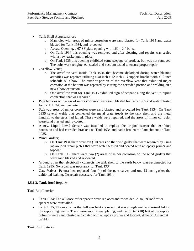
• Tank Shell Appurtenances o Manholes with areas of minor corrosion were sand blasted for Tank 1935 and water
blasted for Tank 1934, and re-coated. o Access Opening, a 67 SF plate opening with 160 – ¾” bolts. o On Tank 1934 this opening was removed and after cleaning and repairs was sealed
with a new gasket put in place. o On Tank 1935 this opening exhibited some seepage of product, but was not removed.
The bolts were retightened, sealed and vacuum tested to ensure proper repair. • Overflow Vents;
o The overflow vent inside Tank 1934 that became dislodged during water blasting activities was repaired utilizing a 48 inch x 12 inch x ¼ support bracket with a 12 inch schedule 80 elbow. The exterior portion of the overflow vent that exhibited major corrosion at the bottom was repaired by cutting the corroded portion and welding on a new elbow extension.
o One overflow vent for Tank 1935 exhibited sign of seepage along the vent-to-piping connection that was repaired.
• Pipe Nozzles with areas of minor corrosion were sand blasted for Tank 1935 and water blasted for Tank 1934, and re-coated.
• Stairway areas of minor corrosion were sand blasted and re-coated for Tank 1934. On Tank 1935 several welds that connected the metal grate treads to the tank shell and the metal handrail to the steps had failed. These welds were repaired, and the areas of minor corrosion were sand blasted and re-coated.
• A new Liquid Level Sensor was installed to replace the original sensor that exhibited corrosion and had corroded brackets on Tank 1934 and had a broken roof attachment on Tank 1935.
• Wind Girders; o On Tank 1934 there were ten (10) areas on the wind girder that were repaired by using
lap-welded repair plates that were water blasted and coated with an epoxy primer and topcoat.
o On Tank 1935 there were two (2) areas of minor corrosion on the wind girders that were sand blasted and re-coated.
• Ground Strap that electrically connects the tank shell to the earth below was reconnected for Tank 1935. No repair was necessary for Tank 1934.
• Gate Valves; Peterra Inc. replaced four (4) of the gate valves and one 12-inch gasket that exhibited leaking. No repair necessary for Tank 1934.
1.5.1.3. Tank Roof Repairs Tank Roof Interior
• Tank 1934; The 43 loose rafter spacers were replaced and re-welded. Also, 59 roof rafter spacers were reinstalled.
• Tank 1935; The roof rafter that fell was bent at one end, it was straightened and re-welded to the supporting beams. The interior roof rafters, plating, and the top ten (10) feet of the support columns were sand blasted and coated with an epoxy primer and topcoat, Ameron Amercoat 395FD.
Tank Roof Exterior
Performance Management Contract Technical Description Fuel Bulk Storage Facility and Pipelines July 2009
6
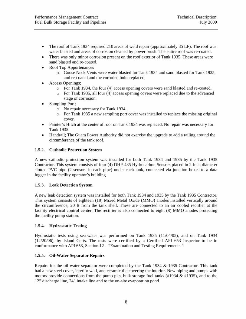
• The roof of Tank 1934 required 210 areas of weld repair (approximately 35 LF). The roof was water blasted and areas of corrosion cleaned by power brush. The entire roof was re-coated.
• There was only minor corrosion present on the roof exterior of Tank 1935. These areas were sand blasted and re-coated.
• Roof Top Appurtenances o Goose Neck Vents were water blasted for Tank 1934 and sand blasted for Tank 1935,
and re-coated and the corroded bolts replaced. • Access Openings;
o For Tank 1934, the four (4) access opening covers were sand blasted and re-coated. o For Tank 1935, all four (4) access opening covers were replaced due to the advanced
stage of corrosion. • Sampling Port;
o No repair necessary for Tank 1934. o For Tank 1935 a new sampling port cover was installed to replace the missing original
cover. • Painter’s Hitch at the center of roof on Tank 1934 was replaced. No repair was necessary for
Tank 1935. • Handrail; The Guam Power Authority did not exercise the upgrade to add a railing around the
circumference of the tank roof. 1.5.2. Cathodic Protection System A new cathodic protection system was installed for both Tank 1934 and 1935 by the Tank 1935 Contractor. This system consists of four (4) DHP-485 Hydrocarbon Sensors placed in 2-inch diameter slotted PVC pipe (2 sensors in each pipe) under each tank, connected via junction boxes to a data logger in the facility operator’s building. 1.5.3. Leak Detection System A new leak detection system was installed for both Tank 1934 and 1935 by the Tank 1935 Contractor. This system consists of eighteen (18) Mixed Metal Oxide (MMO) anodes installed vertically around the circumference, 20 ft from the tank shell. These are connected to an air cooled rectifier at the facility electrical control center. The rectifier is also connected to eight (8) MMO anodes protecting the facility pump station. 1.5.4. Hydrostatic Testing Hydrostatic tests using sea-water was performed on Tank 1935 (11/04/05), and on Tank 1934 (12/20/06), by Island Certs. The tests were certified by a Certified API 653 Inspector to be in conformance with API 653, Section 12 – “Examination and Testing Requirements.” 1.5.5. Oil-Water Separator Repairs Repairs for the oil water separator were completed by the Tank 1934 & 1935 Contractor. This tank had a new steel cover, interior wall, and ceramic tile covering the interior. New piping and pumps with motors provide connections from the pump pits, bulk storage fuel tanks (#1934 & #1935), and to the 12” discharge line, 24” intake line and to the on-site evaporation pond.
Performance Management Contract Technical Description Fuel Bulk Storage Facility and Pipelines July 2009
7
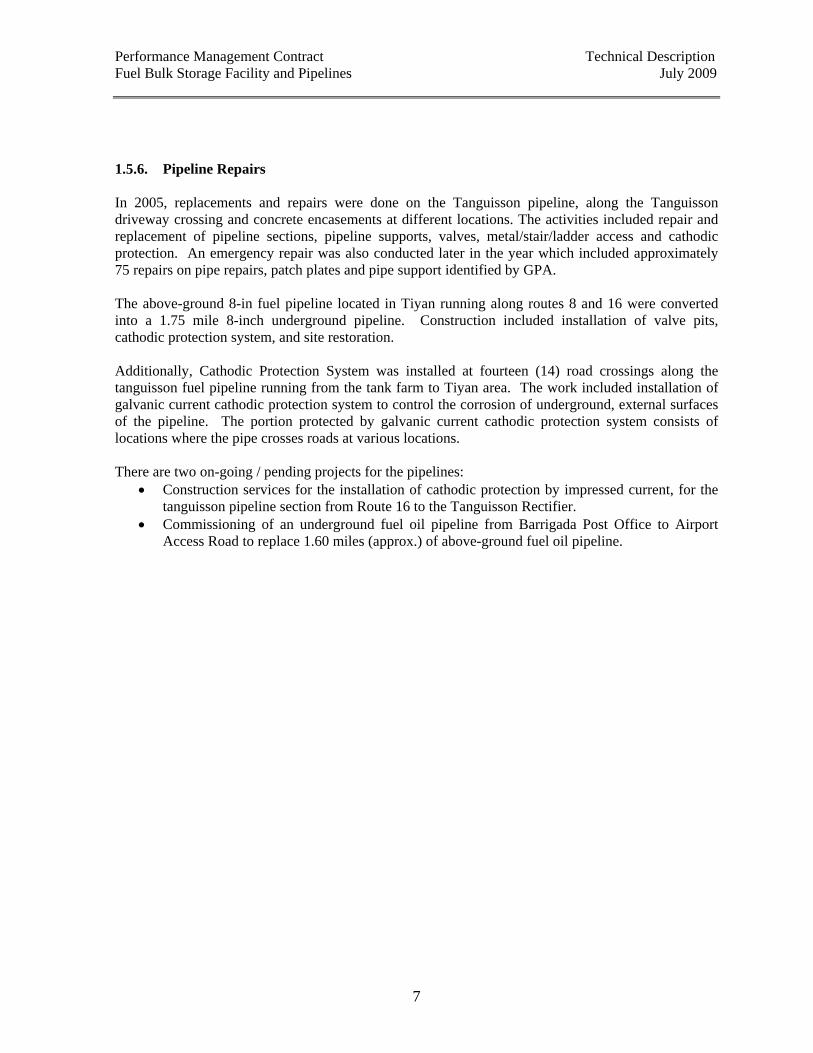
1.5.6. Pipeline Repairs In 2005, replacements and repairs were done on the Tanguisson pipeline, along the Tanguisson driveway crossing and concrete encasements at different locations. The activities included repair and replacement of pipeline sections, pipeline supports, valves, metal/stair/ladder access and cathodic protection. An emergency repair was also conducted later in the year which included approximately 75 repairs on pipe repairs, patch plates and pipe support identified by GPA. The above-ground 8-in fuel pipeline located in Tiyan running along routes 8 and 16 were converted into a 1.75 mile 8-inch underground pipeline. Construction included installation of valve pits, cathodic protection system, and site restoration. Additionally, Cathodic Protection System was installed at fourteen (14) road crossings along the tanguisson fuel pipeline running from the tank farm to Tiyan area. The work included installation of galvanic current cathodic protection system to control the corrosion of underground, external surfaces of the pipeline. The portion protected by galvanic current cathodic protection system consists of locations where the pipe crosses roads at various locations. There are two on-going / pending projects for the pipelines:
• Construction services for the installation of cathodic protection by impressed current, for the tanguisson pipeline section from Route 16 to the Tanguisson Rectifier.
• Commissioning of an underground fuel oil pipeline from Barrigada Post Office to Airport Access Road to replace 1.60 miles (approx.) of above-ground fuel oil pipeline.
Performance Management Contract Technical Description Fuel Bulk Storage Facility and Pipelines July 2009
8
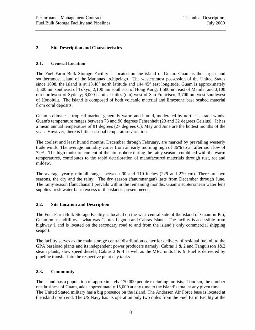
2. Site Description and Characteristics 2.1. General Location The Fuel Farm Bulk Storage Facility is located on the island of Guam. Guam is the largest and southernmost island of the Marianas archipelago. The westernmost possession of the United States since 1898, the island is at 13.48° north latitude and 144.45° east longitude. Guam is approximately 1,500 nm southeast of Tokyo; 2,100 nm southeast of Hong Kong; 1,500 nm east of Manila; and 3,100 nm northwest of Sydney; 6,000 nautical miles (nm) west of San Francisco; 3,700 nm west-southwest of Honolulu. The island is composed of both volcanic material and limestone base seabed material from coral deposits. Guam’s climate is tropical marine; generally warm and humid, moderated by northeast trade winds. Guam's temperature ranges between 73 and 90 degrees Fahrenheit (23 and 32 degrees Celsius). It has a mean annual temperature of 81 degrees (27 degrees C). May and June are the hottest months of the year. However, there is little seasonal temperature variation. The coolest and least humid months, December through February, are marked by prevailing westerly trade winds. The average humidity varies from an early morning high of 86% to an afternoon low of 72%. The high moisture content of the atmosphere during the rainy season, combined with the warm temperatures, contributes to the rapid deterioration of manufactured materials through rust, rot and mildew. The average yearly rainfall ranges between 90 and 110 inches (229 and 279 cm). There are two seasons, the dry and the rainy. The dry season (fanumnangan) lasts from December through June. The rainy season (fanuchanan) prevails within the remaining months. Guam's subterranean water lens supplies fresh water far in excess of the island's present needs. 2.2. Site Location and Description The Fuel Farm Bulk Storage Facility is located on the west central side of the island of Guam in Piti, Guam on a landfill over what was Cabras Lagoon and Cabras Island. The facility is accessible from highway 1 and is located on the secondary road to and from the island’s only commercial shipping seaport. The facility serves as the main storage central distribution center for delivery of residual fuel oil to the GPA baseload plants and its independent power producers namely: Cabras 1 & 2 and Tanguisson 1&2 steam plants, slow speed diesels, Cabras 3 & 4 as well as the MEC units 8 & 9. Fuel is delivered by pipeline transfer into the respective plant day tanks. 2.3. Community The island has a population of approximately 170,000 people excluding tourists. Tourism, the number one business of Guam, adds approximately 15,000 at any time to the island’s total at any given time. The United Stated military has a big presence on the island. The Andersen Air Force base is located at the island north end. The US Navy has its operation only two miles from the Fuel Farm Facility at the
Performance Management Contract Technical Description Fuel Bulk Storage Facility and Pipelines July 2009
9
Cabras site. The United Stated military has proposed to relocate 8,000 marines plus families to Guam increasing the military presence on the island. The US Navy recently turned over the operation of the shipyard to a private contractor. The private contractor has a multi-year contract to operate the shipyard, primarily in support of the Navy ship repair facility. This facility has tremendous maintenance equipment and capabilities as would be expected of a remote ship repair facility. This facility if utilized properly could be a strategic asset to the PMC contractor in that, maintenance alliances and services may be developed to support various aspects of the facilities maintenance needs. PMCs are encouraged to support various community activities such as government-sponsored programs, parades and events such as the South Pacific Games held on Guam in 1999. A variety of local vendors supply important services to the site as follows:
• Rental Equipment; • Electrical and Mechanical Parts; • Various Tools and Consumable Materials; • Janitorial Services; • Welding and Machining Supplies; • Hardware Supplies; • Construction Equipment; • The Former US Navy Shipyard Maintenance Facilities with Tremendous Machining and
Repair Capacity. PMC’s are also encouraged to participate in the following community affairs: Liberation Day (GPA sponsored float in parade), Labor Day Government of Guam Picnic, Military Reserves, GPA Public Power Week and associated island wide clean-up activities, GPA sponsors Fitness & Wellness program where an employee can use three hours of the normal base 40 hours each week to exercise and receive normal pay. 2.4. Site Map Site maps will be provided upon request. 2.5. Site Infrastructure / Utilities The facility’s utilities include potable water, electric power, communications and sewage discharge lines. 2.5.1. Domestic Water Domestic potable water is provided to the facility by the US Navy reservoir located near by. This source of water is inter-connected to the power plant for the water treatment and all other potable needs. The same water supply charges the fire hydrants on the plant property and no plant booster pumps are required.
Performance Management Contract Technical Description Fuel Bulk Storage Facility and Pipelines July 2009
10
2.5.2. Electrical Power The power system for the Fuel Farm Facility comes from GPA’s substations and then distributed from there to the customers. 2.5.3. Station Lighting The facility has perimeter lighting. 2.5.4. Communications System Facility personnel can be contacted on several primary and secondary communication devices during fuel shipments, transfer operations, emergency response operations, and remote operations. The communication devices currently used by the current contractor (Peterra, Inc. ) includes the following:
• I-connect radio (6333) • Landline (477-6333) • Cellular Telephones (888-6333/ 888-9387/ 888-9392) • Pagers • Two-way VHF radio
Facility personnel are equipped with I-connect radios which are convenient for contacting other personnel, including the security guard, local O.S.R.O. (G.R.S.L.), Guam EPA and other local agencies. Landlines and pagers are often used to contact personnel outside the facility. The VHF radios are typically used when coordinating vessel cargo receiving activities with other parties involved in fuel movement operations, or for contacting other facility personnel. The VHF radios provided by the facility meet Class 1, Division 1, Group D requirements defined in 46CFR110.80 for intrinsically safe radios. 2.6. Incident Mitigation Capabilities The facility has a series of Standard Operating Procedures (SOP) which are employed GPA wide. The following SOP’s pertain to these issues:
• SP-049 Tropical Cyclone Emergency System Restoration (ESR); • SP-050 Oil Spill Containment, Clean-up and Reporting; • SP-057 Supplements I through VII to the Hazard Communication Program; • SP-063 Hazard Communication Program; • SP-067 Employees Hazard Reporting; • SP-088 Emergency Condition (Support Services Section).
2.7. On-site Safety Equipment The current contractor has the following safety equipment:
• 10, 20 and 32-pound fire extinguishers located in the pump stations, office and storage room; • Personal Protective Equipment (PPE’s), first aid kits, absorbent pads, kitty litter, and spill kits
located in the office, storage look, and from the local OSRO (Guam Response Services Ltd.) which is located 3 minutes from the facility
Performance Management Contract Technical Description Fuel Bulk Storage Facility and Pipelines July 2009
11
3. Fuel Bulk Storage Facility and Pipelines Technical Description Initial operation of the Fuel Farm Bulk Storage Facility began in 1976. The facility is situated on a small track of land on the islands west central side. Schedule A describes the description and operation of the facility developed by its current contractor, Peterra, Inc. This document shall be enhanced by the PMC contractor to address current and future issues. Schedules F and G illustrates the Fuel Facility Lay Out and RFO Refueling Schematic Diagram. 3.1. Storage Tanks and Related Systems The two bulk storage tanks at the Piti Tank Farm are approximately 48 ft high with a diameter of 200 ft, having capacity of approximately 254,000 barrels each. They are supplied by a 24” above-ground pipeline that is interconnected to the U.S. Navy and Shell Tank farms. The supply line terminates with a double gate valve at Tank 1935 and a single gate valve at Tank 1934. Discharge from the tanks is through a 12” pipeline with a gate valve at the tank discharge port. This piping is connected to a pump manifold that distributes fuel to Cabras 1&2, Cabras 3&4 and Tanguisson 1&2 Power Plants. A schematic diagram of the fuel distribution system is illustrated in Volume VI Appendices F and G.
3.1.1. Bulk Residual Fuel Oil (RFO) Storage Description of equipment and system: Fuel Oils – Bulk Residual Fuel Oil is the main fuel feedstock used in the operation of the baseload (steam) power plants namely, the Cabras 1&2 , Cabras 3&4, Marianas Energy Corporation (MEC), and Tanguisson Power plants for generation of electricity for the islandwide power supply requirement. Bulk Residual Fuel Oil is being imported via oceanfreight cargo vessels from off-island supplier and is received via the twenty-four (24) inch pipeline from Shell F-1 Dock facilities into the GPA Bulk Storage Tank 1934 and Tank 1935 and the GPA-Leased (Shell) Storage Tank 1902, Tank 1910, and Tank 1911. Fuel Oil Storage Tank – The facility has two (2) bulk storage tank of 254,000-BBL storage capacity each. The tanks are approximately 200 feet in diameter and 48 feet high. Tank 1934 is currently assigned for LSFO (1.19%w sulfur max) storage and Tank 1935 is for HSFO (2.00%w sulfur max) storage. The tanks distribute fuel to all the baseload power plant daytanks. Tanks were re-calibrated in 2007 by SGS Guam, Inc. Updated calibration tables for Tank 1934 and Tank 1935 can be found in Schedules D and E. The current configuration for the storage tanks are as follows:
Table 1. High Sulfur Fuel Oil, 2.00%w sulfur max (HSFO) Storage Storage Tanks Location Storage Capacity
Tank 1935 GPA Fuel Farm 250,000 bbls Tank 1902 Shell TankFarm (GPA-leased) 38,000 bbls Total HSFO Inventory Capacity 614,000 bbls
Performance Management Contract Technical Description Fuel Bulk Storage Facility and Pipelines July 2009
12
Table 2. Low Sulfur Fuel Oil, 1.19%w sulfur max. (LSFO) Storage Storage Tanks Location Storage Capacity
Tank 1934 GPA Fuel Farm 250,000 bbls Tank 1910 Shell TankFarm (GPA-leased) 38,000 bbls Tank 1911 Shell TankFarm (GPA-leased) 38,000 bbls Total LSFO Inventory Capacity 614,000 bbls
Residual Fuel Oil may be transferred from GPA-Leased (Shell) Tanks into the GPA Bulk Storage Facility via pipeline transfers utilizing Shell transfer pump. Residual Fuel Oil may be delivered from the GPA Bulk Storage Tank 1934 or Tank 1935 into the respective power plant daytanks via pipeline transfers utilizing the GPA Fuel Farm Transfer Pump Station. Residual Fuel Oil may be delivered from the GPA- Leased (Shell) Tank 1902, Tank 1910, or Tank 1911 into the respective power plant daytanks via pipeline transfers utilizing the Shell transfer Pump station in combination with the GPA Fuel Farm Transfer Pump Station.
3.1.2. Diesel Oil Storage Description of equipment: Diesel Oil Tank - The facility has one (1) outdoor C.R.T. type, 5,000-gallon capacity tank. The tank services fuel to the diesel-driven auxiliary transfer pump which serves as back-up to the main transfer pumps. 3.1.3. Fuel Oil Transfer Pumps 3.1.3.1. Cabras Plants Four (4) pumps are assigned for fuel transfer to Cabras 1&2, Cabras 3&4, and MEC 8&9 power plants. Up to two(2) pumps are operating at the same time depending on the demand for fuel transfer. Two (2) pumps are always available as stand-by. The pumps are arranged in parallel and have a capacity of 700 bbls/hr each operating at a maximum pressure of 250 psig. (500SSU at 120 degree F). Complete pump specifications is described in Schedule C. Two of the pumps were installed in 1976, and two were installed in 2007 during Facility Upgrade.
3.1.3.2. Tanguisson Plant Three (3) pumps are assigned for fuel transfer to Tanguisson Power Plant. Up to two (2) pumps are operating at the same time depending on the demand for fuel transfer. One (1) pump is available on
Performance Management Contract Technical Description Fuel Bulk Storage Facility and Pipelines July 2009
13
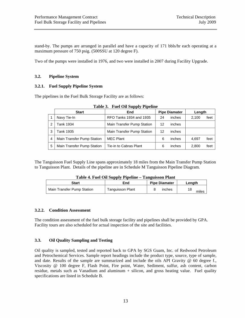
stand-by. The pumps are arranged in parallel and have a capacity of 171 bbls/hr each operating at a maximum pressure of 750 psig. (500SSU at 120 degree F). Two of the pumps were installed in 1976, and two were installed in 2007 during Facility Upgrade. 3.2. Pipeline System 3.2.1. Fuel Supply Pipeline System The pipelines in the Fuel Bulk Storage Facility are as follows:
Table 3. Fuel Oil Supply Pipeline Start End Pipe Diamater Length 1 Navy Tie-In RFO Tanks 1934 and 1935 24 inches 2,100 feet
2 Tank 1934 Main Transfer Pump Station 12 inches
3 Tank 1935 Main Transfer Pump Station 12 inches
4 Main Transfer Pump Station MEC Plant 6 inches 4,697 feet
5 Main Transfer Pump Station Tie-in to Cabras Plant 6 inches 2,800 feet
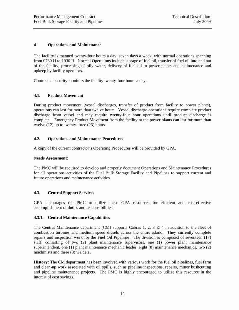
The Tanguisson Fuel Supply Line spans approximately 18 miles from the Main Transfer Pump Station to Tanguisson Plant. Details of the pipeline are in Schedule M Tanguisson Pipeline Diagram.
Table 4. Fuel Oil Supply Pipeline – Tanguisson Plant Start End Pipe Diamater Length
Main Transfer Pump Station Tanguisson Plant 8 inches 18 miles
3.2.2. Condition Assessment The condition assessment of the fuel bulk storage facility and pipelines shall be provided by GPA. Facility tours are also scheduled for actual inspection of the site and facilities. 3.3. Oil Quality Sampling and Testing Oil quality is sampled, tested and reported back to GPA by SGS Guam, Inc. of Redwood Petroleum and Petrochemical Services. Sample report headings include the product type, source, type of sample, and date. Results of the sample are summarized and include the oils API Gravity @ 60 degree f., Viscosity @ 100 degree F, Flash Point, Fire point, Water, Sediment, sulfur, ash content, carbon residue, metals such as Vanadium and aluminum + silicon, and gross heating value. Fuel quality specifications are listed in Schedule B.
Performance Management Contract Technical Description Fuel Bulk Storage Facility and Pipelines July 2009
14
4. Operations and Maintenance The facility is manned twenty-four hours a day, seven days a week, with normal operations spanning from 0730 H to 1930 H. Normal Operations include storage of fuel oil, transfer of fuel oil into and out of the facility, processing of oily water, delivery of fuel oil to power plants and maintenance and upkeep by facility operators. Contracted security monitors the facility twenty-four hours a day. 4.1. Product Movement During product movement (vessel discharges, transfer of product from facility to power plants), operations can last for more than twelve hours. Vessel discharge operations require complete product discharge from vessel and may require twenty-four hour operations until product discharge is complete. Emergency Product Movement from the facility to the power plants can last for more than twelve (12) up to twenty-three (23) hours. 4.2. Operations and Maintenance Procedures A copy of the current contractor’s Operating Procedures will be provided by GPA. Needs Assessment: The PMC will be required to develop and properly document Operations and Maintenance Procedures for all operations activities of the Fuel Bulk Storage Facility and Pipelines to support current and future operations and maintenance activities. 4.3. Central Support Services GPA encourages the PMC to utilize these GPA resources for efficient and cost-effective accomplishment of duties and responsibilities. 4.3.1. Central Maintenance Capabilities The Central Maintenance department (CM) supports Cabras 1, 2, 3 & 4 in addition to the fleet of combustion turbines and medium speed diesels across the entire island. They currently complete repairs and inspection work for the Fuel Oil Pipelines. The division is composed of seventeen (17) staff, consisting of two (2) plant maintenance supervisors, one (1) power plant maintenance superintendent, one (1) plant maintenance mechanic leader, eight (8) maintenance mechanics, two (2) machinists and three (3) welders. History: The CM department has been involved with various work for the fuel oil pipelines, fuel farm and clean-up work associated with oil spills, such as pipeline inspections, repairs, minor bushcutting and pipeline maintenance projects. The PMC is highly encouraged to utilize this resource in the interest of cost savings.
Performance Management Contract Technical Description Fuel Bulk Storage Facility and Pipelines July 2009
15
4.3.2. Central Warehousing Capabilities The warehouse stores spare and replacement parts and components required for reliable operation of the Cabras facility. One full time employee staffs the warehouse. 4.3.3. Generation Administration Capabilities The Generation Department is located on the Cabras plant property. The group is comprised of one Assistant Manager for Generation, two electrical engineers and one mechanical engineer that support the needs of the power plants. Department personnel can coordinate with the PMC, determine budget inputs, support major outages, and determine what needs to be accomplished to help the long-term viability of the facility. 4.3.4. Engineering Division Capabilities The Engineering Division is responsible for the overall implementation of new capital improvements projects for the Guam Power Authority. These projects range from multi-million dollar construction projects such as the installation of Cabras 3 & 4 Slow-speed Diesel Plant to the line extensions for individual customer services. General Engineering is also responsible for the overall system protection needs. The General Engineering Division is comprised of eight sections:
• Engineering Administration; • Customer Service; • Distribution; • Project Management; • Real Estate; • Substation / Transmission;
The Division has 35 personnel with varying skill levels from the licensed professional engineers to engineering technicians and the field survey crews. 4.3.5. Computerized Maintenance Management System In 1997 GPA initiated the implementation of the Computerized Maintenance Management System (CMMS) under the J.D. Edwards (JDE) Financial Management Software for all operations division sections, but primarily for generation, T&D and transportation. Prior to this program, GPA tracked maintenance with a simple database or spreadsheet program, with no standardized maintenance management program in place. History files were not easily accessible and most history resources were retiring. In addition, labor and other project costs tracking became difficult tasks when projects were not setup with appropriate tracking accounts. The CMMS provided an on-line access to equipment for completed, ongoing and upcoming maintenance work orders with an up to date status. Backlog, project costs and labor tracking were easily available through system reporting. The integrated inventory program allowed parts to be viewed on-line and staged before they were to be picked up from the warehouse. The CMMS also
Performance Management Contract Technical Description Fuel Bulk Storage Facility and Pipelines July 2009
16
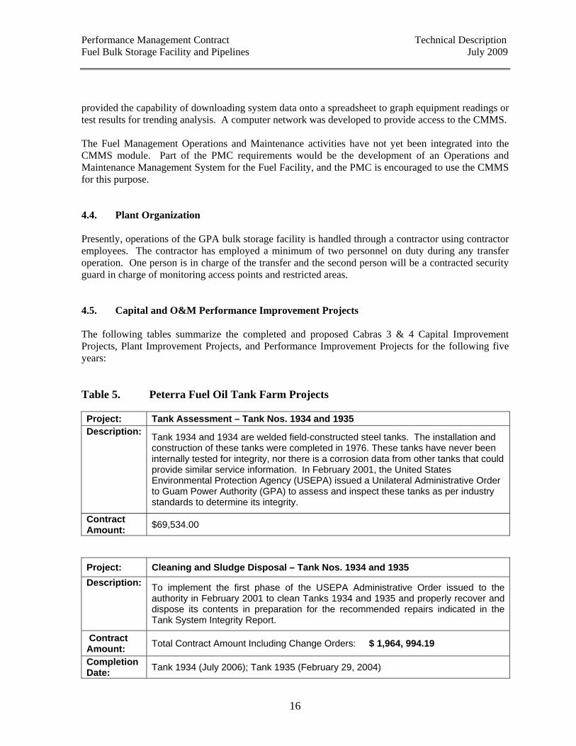
provided the capability of downloading system data onto a spreadsheet to graph equipment readings or test results for trending analysis. A computer network was developed to provide access to the CMMS. The Fuel Management Operations and Maintenance activities have not yet been integrated into the CMMS module. Part of the PMC requirements would be the development of an Operations and Maintenance Management System for the Fuel Facility, and the PMC is encouraged to use the CMMS for this purpose. 4.4. Plant Organization Presently, operations of the GPA bulk storage facility is handled through a contractor using contractor employees. The contractor has employed a minimum of two personnel on duty during any transfer operation. One person is in charge of the transfer and the second person will be a contracted security guard in charge of monitoring access points and restricted areas. 4.5. Capital and O&M Performance Improvement Projects The following tables summarize the completed and proposed Cabras 3 & 4 Capital Improvement Projects, Plant Improvement Projects, and Performance Improvement Projects for the following five years: Table 5. Peterra Fuel Oil Tank Farm Projects Project: Tank Assessment – Tank Nos. 1934 and 1935 Description: Tank 1934 and 1934 are welded field-constructed steel tanks. The installation and
construction of these tanks were completed in 1976. These tanks have never been internally tested for integrity, nor there is a corrosion data from other tanks that could provide similar service information. In February 2001, the United States Environmental Protection Agency (USEPA) issued a Unilateral Administrative Order to Guam Power Authority (GPA) to assess and inspect these tanks as per industry standards to determine its integrity.
Contract Amount: $69,534.00
Project: Cleaning and Sludge Disposal – Tank Nos. 1934 and 1935 Description: To implement the first phase of the USEPA Administrative Order issued to the
authority in February 2001 to clean Tanks 1934 and 1935 and properly recover and dispose its contents in preparation for the recommended repairs indicated in the Tank System Integrity Report.
Contract Amount: Total Contract Amount Including Change Orders: $ 1,964, 994.19
Completion Date: Tank 1934 (July 2006); Tank 1935 (February 29, 2004)
Performance Management Contract Technical Description Fuel Bulk Storage Facility and Pipelines July 2009
17
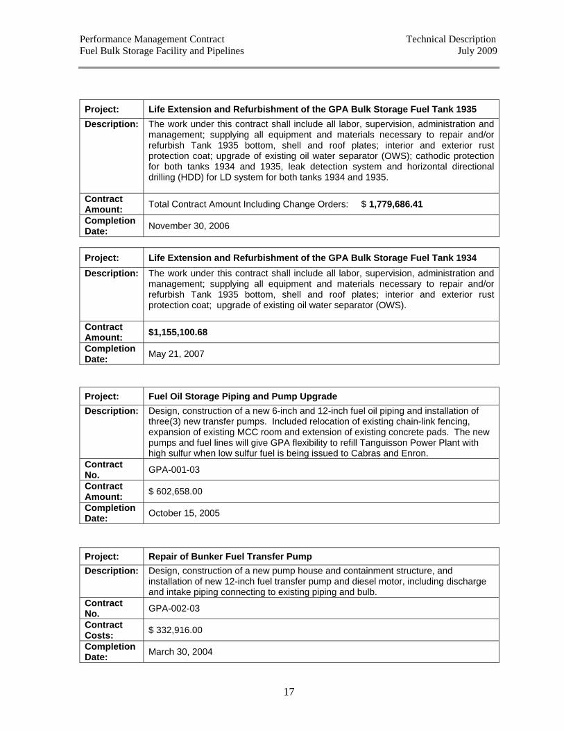
Project: Life Extension and Refurbishment of the GPA Bulk Storage Fuel Tank 1935 Description: The work under this contract shall include all labor, supervision, administration and
management; supplying all equipment and materials necessary to repair and/or refurbish Tank 1935 bottom, shell and roof plates; interior and exterior rust protection coat; upgrade of existing oil water separator (OWS); cathodic protection for both tanks 1934 and 1935, leak detection system and horizontal directional drilling (HDD) for LD system for both tanks 1934 and 1935.
Contract Amount: Total Contract Amount Including Change Orders: $ 1,779,686.41
Completion Date: November 30, 2006
Project: Life Extension and Refurbishment of the GPA Bulk Storage Fuel Tank 1934 Description: The work under this contract shall include all labor, supervision, administration and
management; supplying all equipment and materials necessary to repair and/or refurbish Tank 1935 bottom, shell and roof plates; interior and exterior rust protection coat; upgrade of existing oil water separator (OWS).
Contract Amount: $1,155,100.68
Completion Date: May 21, 2007
Project: Fuel Oil Storage Piping and Pump Upgrade Description: Design, construction of a new 6-inch and 12-inch fuel oil piping and installation of
three(3) new transfer pumps. Included relocation of existing chain-link fencing, expansion of existing MCC room and extension of existing concrete pads. The new pumps and fuel lines will give GPA flexibility to refill Tanguisson Power Plant with high sulfur when low sulfur fuel is being issued to Cabras and Enron.
Contract No. GPA-001-03
Contract Amount: $ 602,658.00
Completion Date: October 15, 2005
Project: Repair of Bunker Fuel Transfer Pump Description: Design, construction of a new pump house and containment structure, and
installation of new 12-inch fuel transfer pump and diesel motor, including discharge and intake piping connecting to existing piping and bulb.
Contract No. GPA-002-03
Contract Costs: $ 332,916.00
Completion Date: March 30, 2004
Performance Management Contract Technical Description Fuel Bulk Storage Facility and Pipelines July 2009
18
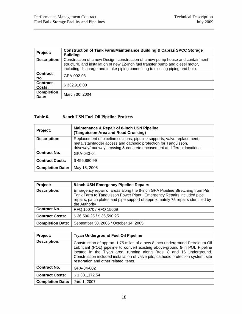
Project: Construction of Tank Farm/Maintenance Building & Cabras SPCC Storage Building
Description: Construction of a new Design, construction of a new pump house and containment structure, and installation of new 12-inch fuel transfer pump and diesel motor, including discharge and intake piping connecting to existing piping and bulb.
Contract No. GPA-002-03
Contract Costs: $ 332,916.00
Completion Date: March 30, 2004
Table 6. 8-inch USN Fuel Oil Pipeline Projects
Project: Maintenance & Repair of 8-inch USN Pipeline (Tanguisson Area and Road Crossing)
Description: Replacement of pipeline sections, pipeline supports, valve replacement, metal/stair/ladder access and cathodic protection for Tanguisson, driveway/roadway crossing & concrete encasement at different locations.
Contract No. GPA-043-04
Contract Costs: $ 456,880.99
Completion Date: May 15, 2005 Project: 8-Inch USN Emergency Pipeline Repairs Description: Emergency repair of areas along the 8-inch GPA Pipeline Stretching from Piti
Tank Farm to Tanguisson Power Plant. Emergency Repairs included pipe repairs, patch plates and pipe support of approximately 75 repairs identified by the Authority
Contract No. RFQ 15070 / RFQ 15069 Contract Costs: $ 36,590.25 / $ 36,590.25
Completion Date: September 30, 2005 / October 14, 2005 Project: Tiyan Underground Fuel Oil Pipeline Description: Construction of approx. 1.75 miles of a new 8-inch underground Petroleum Oil
Lubricant (POL) pipeline to convert existing above-ground 8-in POL Pipeline located in the Tiyan area, running along Rtes. 8 and 16 underground. Construction included installation of valve pits, cathodic protection system, site restoration and other related items.
Contract No. GPA-04-002
Contract Costs: $ 1,381,172.54 Completion Date: Jan. 1, 2007
Performance Management Contract Technical Description Fuel Bulk Storage Facility and Pipelines July 2009
19
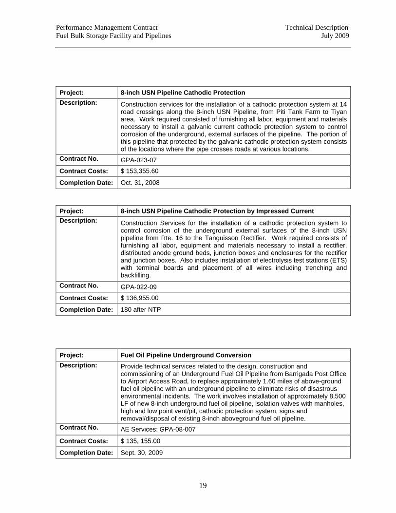
Project: 8-inch USN Pipeline Cathodic Protection Description: Construction services for the installation of a cathodic protection system at 14
road crossings along the 8-inch USN Pipeline, from Piti Tank Farm to Tiyan area. Work required consisted of furnishing all labor, equipment and materials necessary to install a galvanic current cathodic protection system to control corrosion of the underground, external surfaces of the pipeline. The portion of this pipeline that protected by the galvanic cathodic protection system consists of the locations where the pipe crosses roads at various locations.
Contract No. GPA-023-07
Contract Costs: $ 153,355.60
Completion Date: Oct. 31, 2008 Project: 8-inch USN Pipeline Cathodic Protection by Impressed Current Description: Construction Services for the installation of a cathodic protection system to
control corrosion of the underground external surfaces of the 8-inch USN pipeline from Rte. 16 to the Tanguisson Rectifier. Work required consists of furnishing all labor, equipment and materials necessary to install a rectifier, distributed anode ground beds, junction boxes and enclosures for the rectifier and junction boxes. Also includes installation of electrolysis test stations (ETS) with terminal boards and placement of all wires including trenching and backfilling.
Contract No. GPA-022-09
Contract Costs: $ 136,955.00
Completion Date: 180 after NTP Project: Fuel Oil Pipeline Underground Conversion Description: Provide technical services related to the design, construction and
commissioning of an Underground Fuel Oil Pipeline from Barrigada Post Office to Airport Access Road, to replace approximately 1.60 miles of above-ground fuel oil pipeline with an underground pipeline to eliminate risks of disastrous environmental incidents. The work involves installation of approximately 8,500 LF of new 8-inch underground fuel oil pipeline, isolation valves with manholes, high and low point vent/pit, cathodic protection system, signs and removal/disposal of existing 8-inch aboveground fuel oil pipeline.
Contract No. AE Services: GPA-08-007
Contract Costs: $ 135, 155.00
Completion Date: Sept. 30, 2009
Performance Management Contract Technical Description Fuel Bulk Storage Facility and Pipelines July 2009
20
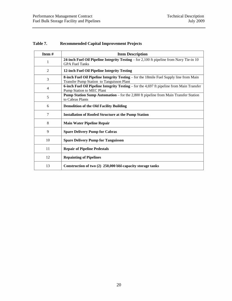
Table 7. Recommended Capital Improvement Projects
Item # Item Description
1 24-inch Fuel Oil Pipeline Integrity Testing – for 2,100 ft pipeline from Navy Tie-in 10 GPA Fuel Tanks
2 12-inch Fuel Oil Pipeline Integrity Testing
3 8-inch Fuel Oil Pipeline Integrity Testing – for the 18mile Fuel Supply line from Main Transfer Pump Station to Tanguisson Plant
4 6-inch Fuel Oil Pipeline Integrity Testing – for the 4,697 ft pipeline from Main Transfer Pump Station to MEC Plant
5 Pump Station Sump Automation – for the 2,800 ft pipeline from Main Transfer Station to Cabras Plants
6 Demolition of the Old Facility Building
7 Installation of Roofed Structure at the Pump Station
8 Main Water Pipeline Repair
9 Spare Delivery Pump for Cabras
10 Spare Delivery Pump for Tanguisson
11 Repair of Pipeline Pedestals
12 Repainting of Pipelines
13 Construction of two (2) 250,000 bbl-capacity storage tanks
Performance Management Contract Technical Description Fuel Bulk Storage Facility and Pipelines July 2009
21
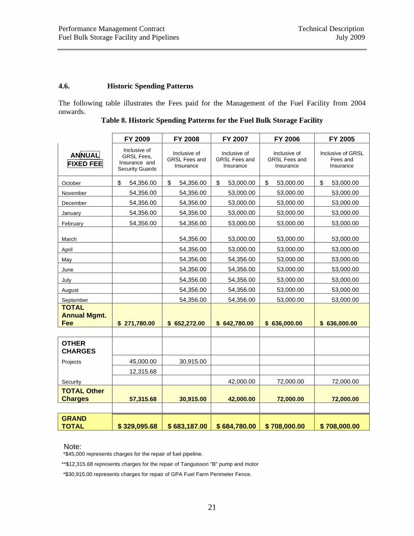
4.6. Historic Spending Patterns The following table illustrates the Fees paid for the Management of the Fuel Facility from 2004 onwards.
Table 8. Historic Spending Patterns for the Fuel Bulk Storage Facility
FY 2009 FY 2008 FY 2007 FY 2006 FY 2005
ANNUAL FIXED FEE
Inclusive of GRSL Fees,
Insurance and Security Guards
Inclusive of GRSL Fees and
Insurance
Inclusive of GRSL Fees and
Insurance
Inclusive of GRSL Fees and
Insurance
Inclusive of GRSL Fees and Insurance
October $ 54,356.00 $ 54,356.00 $ 53,000.00 $ 53,000.00 $ 53,000.00 November 54,356.00 54,356.00 53,000.00 53,000.00 53,000.00
December 54,356.00 54,356.00 53,000.00 53,000.00 53,000.00
January 54,356.00 54,356.00 53,000.00 53,000.00 53,000.00
February 54,356.00 54,356.00 53,000.00 53,000.00 53,000.00
March 54,356.00 53,000.00 53,000.00 53,000.00
April 54,356.00 53,000.00 53,000.00 53,000.00
May 54,356.00 54,356.00 53,000.00 53,000.00
June 54,356.00 54,356.00 53,000.00 53,000.00
July 54,356.00 54,356.00 53,000.00 53,000.00
August 54,356.00 54,356.00 53,000.00 53,000.00
September 54,356.00 54,356.00 53,000.00 53,000.00 TOTAL Annual Mgmt. Fee $ 271,780.00 $ 652,272.00 $ 642,780.00 $ 636,000.00 $ 636,000.00 OTHER CHARGES Projects 45,000.00 30,915.00 12,315.68 Security 42,000.00 72,000.00 72,000.00 TOTAL Other Charges 57,315.68 30,915.00 42,000.00 72,000.00 72,000.00 GRAND TOTAL $ 329,095.68 $ 683,187.00 $ 684,780.00 $ 708,000.00 $ 708,000.00 Note: *$45,000 represents charges for the repair of fuel pipeline. **$12,315.68 represents charges for the repair of Tanguisson "B" pump and motor *$30,915.00 represents charges for repair of GPA Fuel Farm Perimeter Fence.
Performance Management Contract Technical Description Fuel Bulk Storage Facility and Pipelines July 2009
22
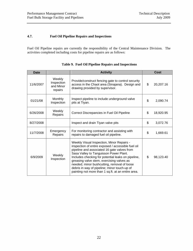
4.7. Fuel Oil Pipeline Repairs and Inspections Fuel Oil Pipeline repairs are currently the responsibility of the Central Maintenance Division. The activities completed including costs for pipeline repairs are as follows:
Table 9. Fuel Oil Pipeline Repairs and Inspections
Date Activity Cost
11/6/2007
Weekly Inspection and Minor
repairs
Provide/construct fencing gate to control security access in the Chaot area (Sinajana). Design and drawing provided by supervisor.
$ 20,207.16
01/21/08 Monthly Inspection
Inspect pipeline to include underground valve pits at Tiyan. $ 2,090.74
6/26/2008 Weekly Repairs Correct Discrepancies in Fuel Oil Pipeline $ 18,920.95
8/27/2008 Inspect and drain Tiyan valve pits $ 3,072.76
11/7/2008 Emergency Repairs
For monitoring contractor and assisting with repairs to damaged fuel oil pipeline. $ 1,669.61
6/9/2009 Weekly Inspection
Weekly Visual Inspection, Minor Repairs - inspection of entire exposed / accessible fuel oil pipeline and associated 16 gate valves from Sasa Valley to Tanguisson Power Plant. Includes checking for potential leaks on pipeline, greasing valve stem, exercising valves as needed; minor bushcutting, removal of loose debris in way of pipeline; minor touch-up of painting not more than 1 sq.ft. at an entire area.
$ 98,123.40
Performance Management Contract Technical Description Fuel Bulk Storage Facility and Pipelines July 2009
23
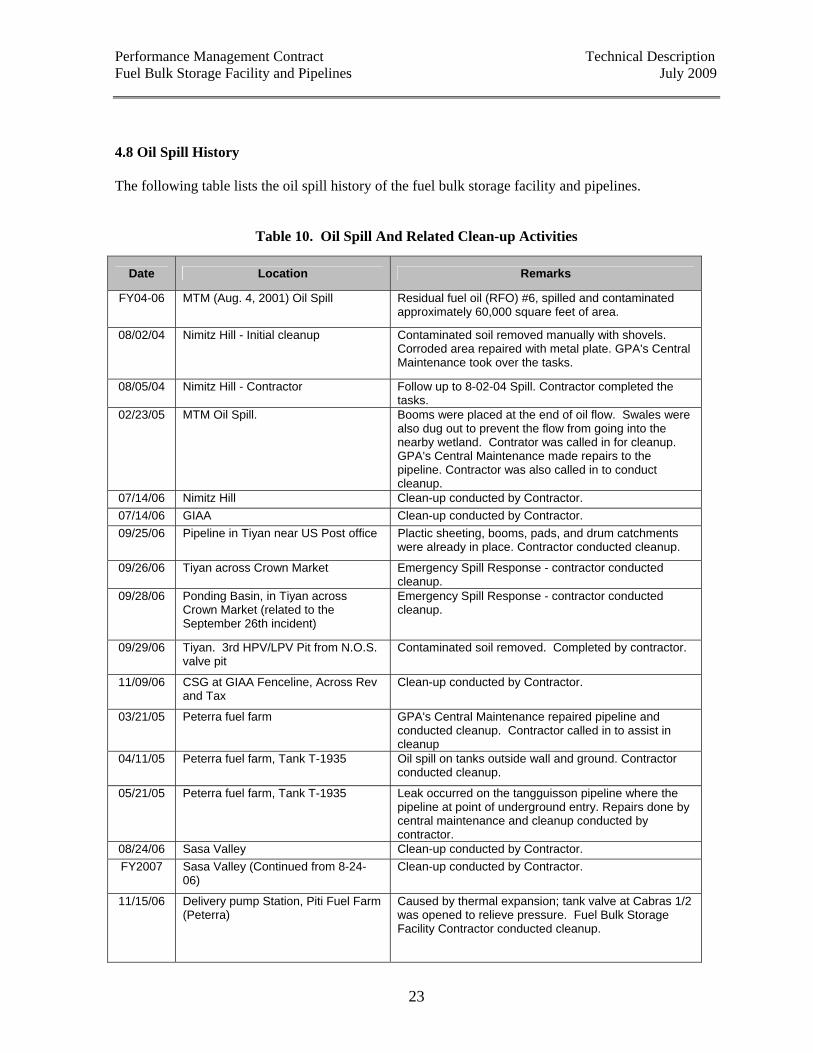
4.8 Oil Spill History The following table lists the oil spill history of the fuel bulk storage facility and pipelines.
Table 10. Oil Spill And Related Clean-up Activities
Date Location Remarks
FY04-06 MTM (Aug. 4, 2001) Oil Spill
Residual fuel oil (RFO) #6, spilled and contaminated approximately 60,000 square feet of area.
08/02/04 Nimitz Hill - Initial cleanup Contaminated soil removed manually with shovels. Corroded area repaired with metal plate. GPA's Central Maintenance took over the tasks.
08/05/04 Nimitz Hill - Contractor Follow up to 8-02-04 Spill. Contractor completed the tasks.
02/23/05 MTM Oil Spill. Booms were placed at the end of oil flow. Swales were also dug out to prevent the flow from going into the nearby wetland. Contrator was called in for cleanup. GPA's Central Maintenance made repairs to the pipeline. Contractor was also called in to conduct cleanup.
07/14/06 Nimitz Hill Clean-up conducted by Contractor. 07/14/06 GIAA Clean-up conducted by Contractor. 09/25/06 Pipeline in Tiyan near US Post office Plactic sheeting, booms, pads, and drum catchments
were already in place. Contractor conducted cleanup.
09/26/06 Tiyan across Crown Market Emergency Spill Response - contractor conducted cleanup.
09/28/06 Ponding Basin, in Tiyan across Crown Market (related to the September 26th incident)
Emergency Spill Response - contractor conducted cleanup.
09/29/06 Tiyan. 3rd HPV/LPV Pit from N.O.S. valve pit
Contaminated soil removed. Completed by contractor.
11/09/06 CSG at GIAA Fenceline, Across Rev and Tax
Clean-up conducted by Contractor.
03/21/05 Peterra fuel farm GPA's Central Maintenance repaired pipeline and conducted cleanup. Contractor called in to assist in cleanup
04/11/05 Peterra fuel farm, Tank T-1935 Oil spill on tanks outside wall and ground. Contractor conducted cleanup.
05/21/05 Peterra fuel farm, Tank T-1935 Leak occurred on the tangguisson pipeline where the pipeline at point of underground entry. Repairs done by central maintenance and cleanup conducted by contractor.
08/24/06 Sasa Valley Clean-up conducted by Contractor. FY2007 Sasa Valley (Continued from 8-24-
06) Clean-up conducted by Contractor.
11/15/06 Delivery pump Station, Piti Fuel Farm (Peterra)
Caused by thermal expansion; tank valve at Cabras 1/2 was opened to relieve pressure. Fuel Bulk Storage Facility Contractor conducted cleanup.

Performance Management Contract Technical Description Fuel Bulk Storage Facility and Pipelines July 2009
24
5. Facility Documentation Summary The following documents shall be provided by the Guam Power Authority:
DOCUMENT LOCATION Fuel Farm Operations Manual Schedule A Fuel Specifications Schedule B Facility Response Plan Schedule C Spill Prevention Control and Countermeasure Plan Schedule D Tank 1934 System Operation and Maintenance Workplan Schedule E RFO Refueling Schematic Diagram Schedule E Fuel Farm Facility Lay-Out Schedule F Cabras Delivery Pump Specification Schedule G Tanguisson Delivery Pump Specification Schedule H Tank 1934 Calibration Table Schedule I Tank 1935 Calibration Table Schedule J Monthly Report Submittal Checklist Schedule K GPA Fuel Farm Operations Logsheet Schedule L Tanguisson Pipeline Diagram Schedule M Fuel Meter Listing Schedule N Meter Installation Diagram Schedule O