Embed Size (px)
Citation preview
Multi video camera calibration and synchronization

Motivation
• Multi camera applications become common.
Example: Stereo, Surveillance….
• Using multi camera we can over come problems like hidden objects.
• In general more cameras equal more information on the scene.
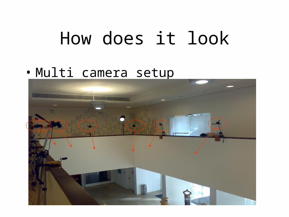
How does it look
• Multi camera setup
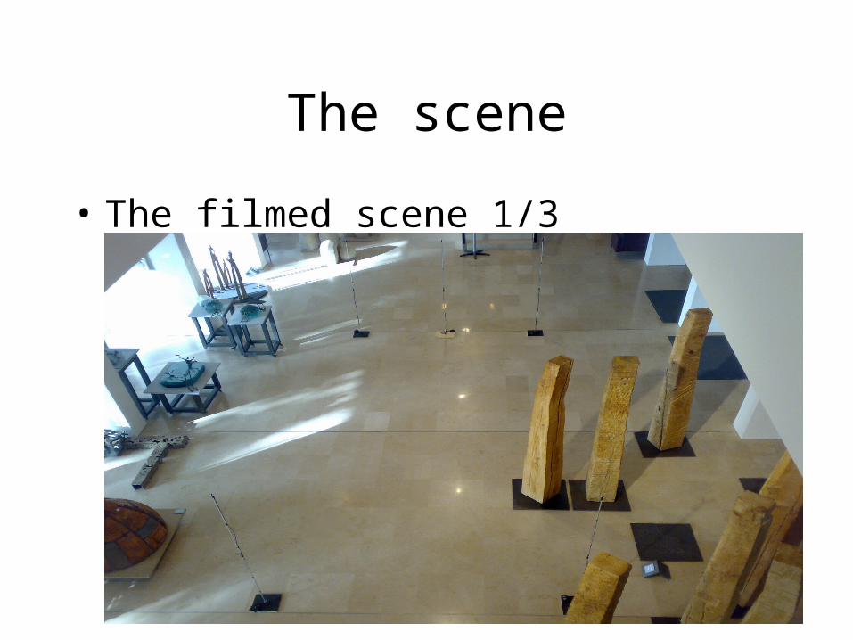
The scene
• The filmed scene 1/3
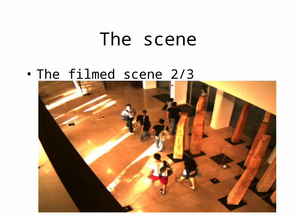
The scene
• The filmed scene 2/3
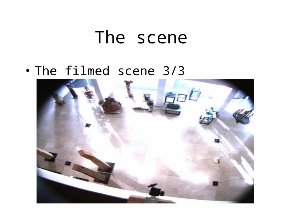
The scene
• The filmed scene 3/3
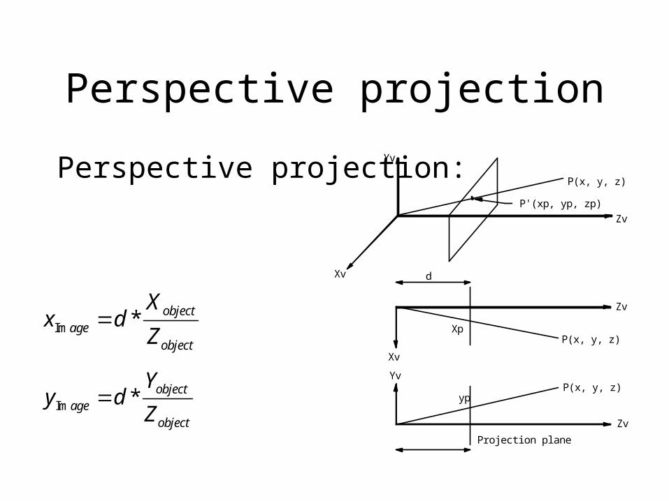
Perspective projection
Perspective projection:
Projection plane
P(x, y, z)
P'(xp, yp, zp)
d
Zv
Xv
Yv
P(x, y, z)
P(x, y, z)
Xp
Xv
Yv
Zv
Zv
yp
Im * objectage
object
Xx d
Z
Im * objectage
object
Yy d
Z
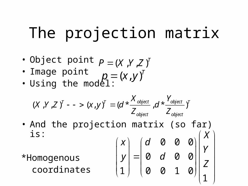
The projection matrix
• Object point • Image point• Using the model:
• And the projection matrix (so far) is:
*Homogenous coordinates
( , , )TP X Y Z( , )Tp x y
( , , ) ( , ) ( * , * )object objectT T T
object object
X YX Y Z x y d d
Z Z
0 0 0
0 0 0
1 0 0 1 01
Xx d
Yy d
Z

Internal matrix
• The internal matrix represent the inner camera settings
• Focal length (d)
• Principle point location usually (0,0)
• Scaling factor
( , )x yo o
( , )x ys s
External matrix
• Includes all the orientation properties of the camera
• Rotation
• Translation
( )camera worldp R p T
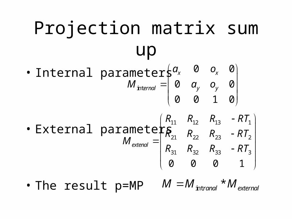
Projection matrix sum up
• Internal parameters
• External parameters
• The result p=MP
int
0 0
0 0
0 0 1 0
x x
ernal y y
a o
M a o
int *ranal externalM M M
11 12 13 1
21 22 23 2
31 32 33 3
0 0 0 1
extenal
R R R RT
R R R RTM
R R R RT
Calibration
• Camera calibration is used to coordinate between cameras.
• Given a 3D point in the real word finding the projected point in the camera.
• The goal is to fined the projection matrix M.• Using known 3D points and there
corresponding image points p=MP can be solved.
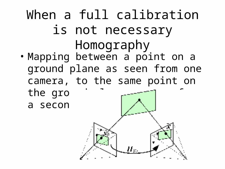
When a full calibration is not necessary Homography
• Mapping between a point on a ground plane as seen from one camera, to the same point on the ground plane as seen from a second camera.
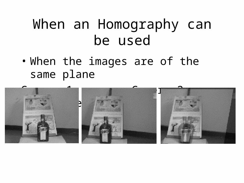
When an Homography can be used
• When the images are of the same plane
Camera 1 Camera 2 Result
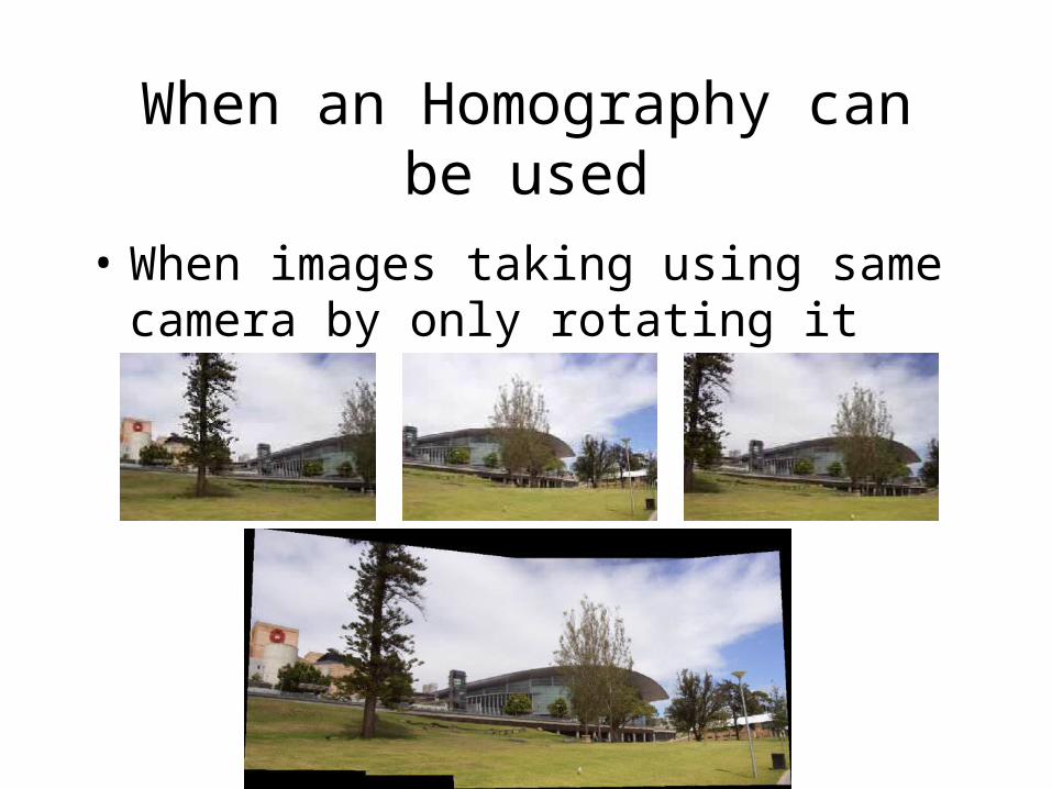
When an Homography can be used
• When images taking using same camera by only rotating it
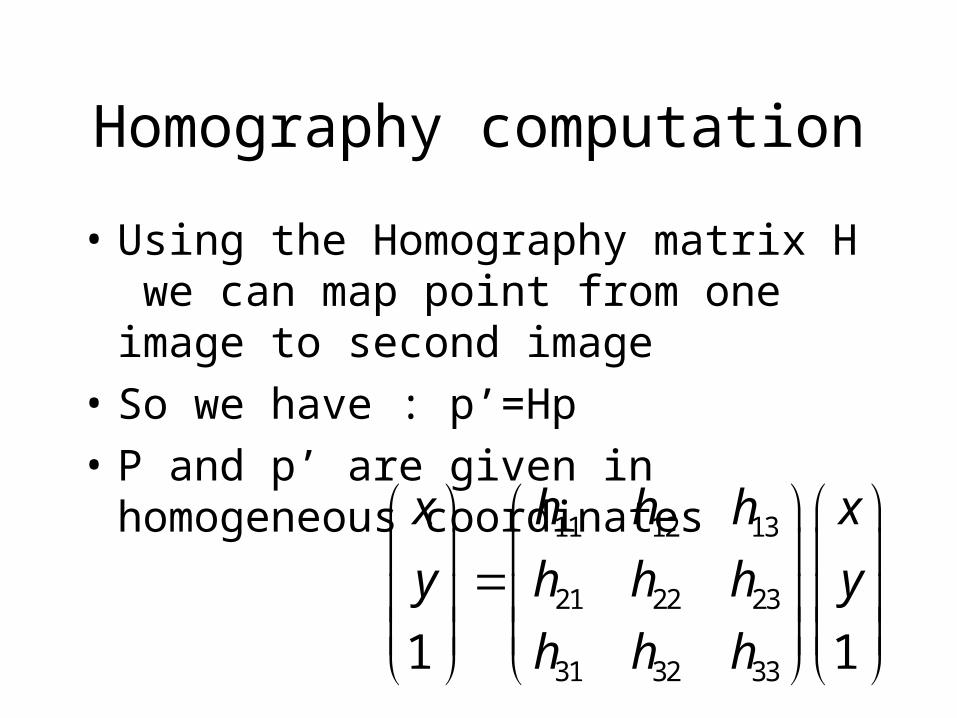
Homography computation
• Using the Homography matrix H we can map point from one image to second image
• So we have : p’=Hp
• P and p’ are given in homogeneous coordinates
11 12 13
21 22 23
31 32 331 1
x h h h x
y h h h y
h h h
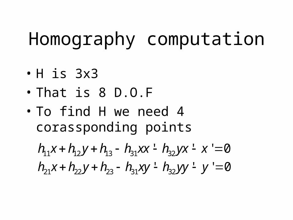
Homography computation
• H is 3x3
• That is 8 D.O.F
• To find H we need 4 corassponding points
11 12 13 31 32' ' ' 0h x h y h h xx h yx x
21 22 23 31 32' ' ' 0h x h y h h xy h yy y
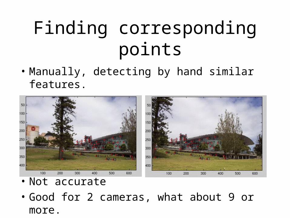
Finding corresponding points
• Manually, detecting by hand similar features.
• Not accurate• Good for 2 cameras, what about 9 or more.
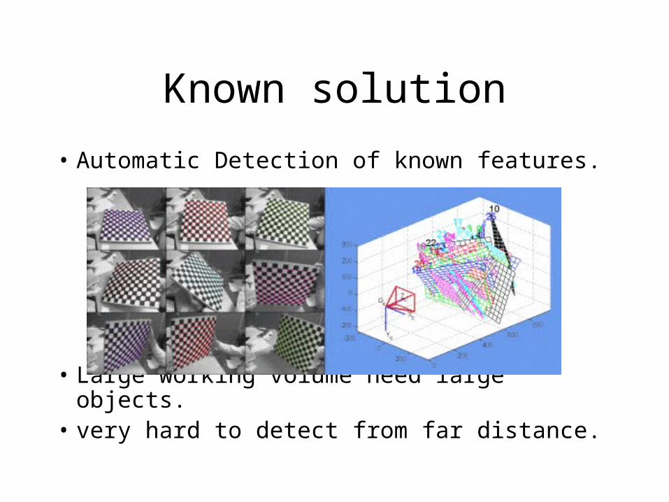
Known solution
• Automatic Detection of known features.
• Large working volume need large objects.• very hard to detect from far distance.
Features detection in wide base line
• Noise
• Hidden parts
• Assuming detection is possible finding the corresponding is hard.
Example of feature detection problems
Goals of the calibration object
• 360 degrees view.
• Robust to noise.
• Accurate regardless the distance (or zoom).
• Easy to find corresponding points.
• Automated as possible.
Solution
• Use easy to detect features (Active features).
• Use the benefits of time dimension video.
• This will create a easy to detect corresponding point list.
• Find Homography using the list of points.
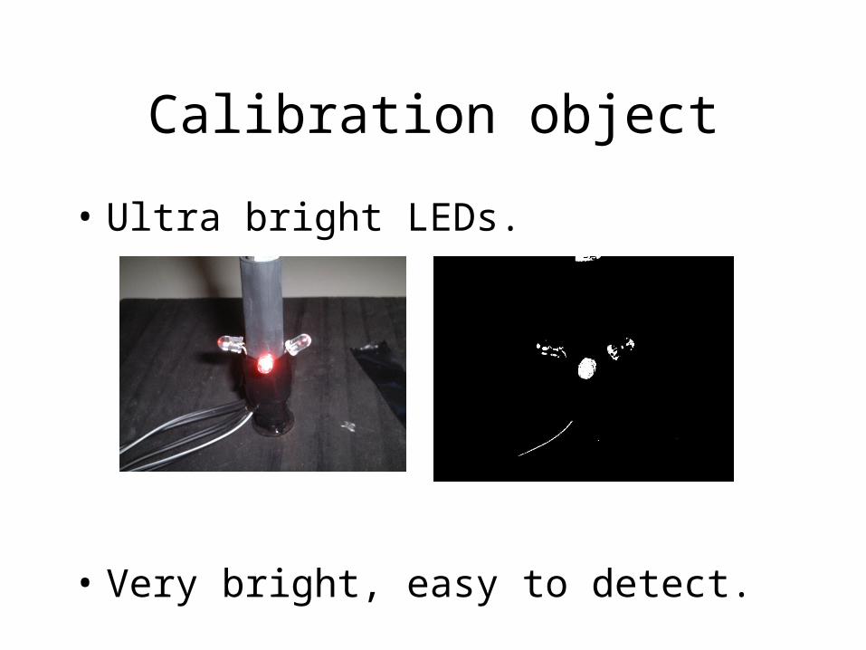
Calibration object
• Ultra bright LEDs.
• Very bright, easy to detect.
Use flickering as identifier
• features flicker in constant rate
• Each feature has a different rate
• The cameras filming in constant rate
• The LED flicker can be found
• The result a list of points in an increasing frequency rate for each camera
Detection method first stage
• Filter unnecessary noise• Use the red channel only as filter.• What about acceptable red channel filters in
RGB such as:R = ((R-B)+(R-G)).• Remove white pixels (All channels have
high intensities ).• Not good for a case a LED caused high
saturation (appears as white).
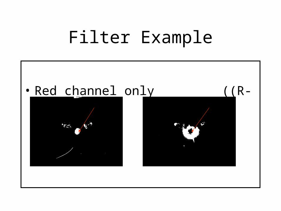
Filter Example
• Red channel only ((R-B)+(R-G))
Detection method second stage
• Take advantage of video camera time line• The LED is going from on to off state• Subtracting following frames (similar to
background subtraction).• Detect features pixels candidates using a
threshold.• Save detection frame number to detect
flickering rate.
Detection method third stage
• So far we have points candidate and there frequencies.
• Yet some of the candidates are noise.
• Use a frequency as a second filter
• Most of the noises have a very short and not consist frequency.
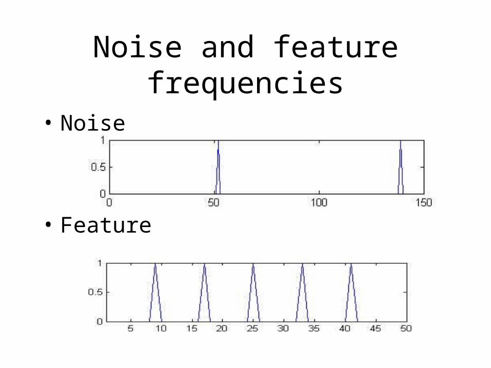
Noise and feature frequencies
• Noise
• Feature
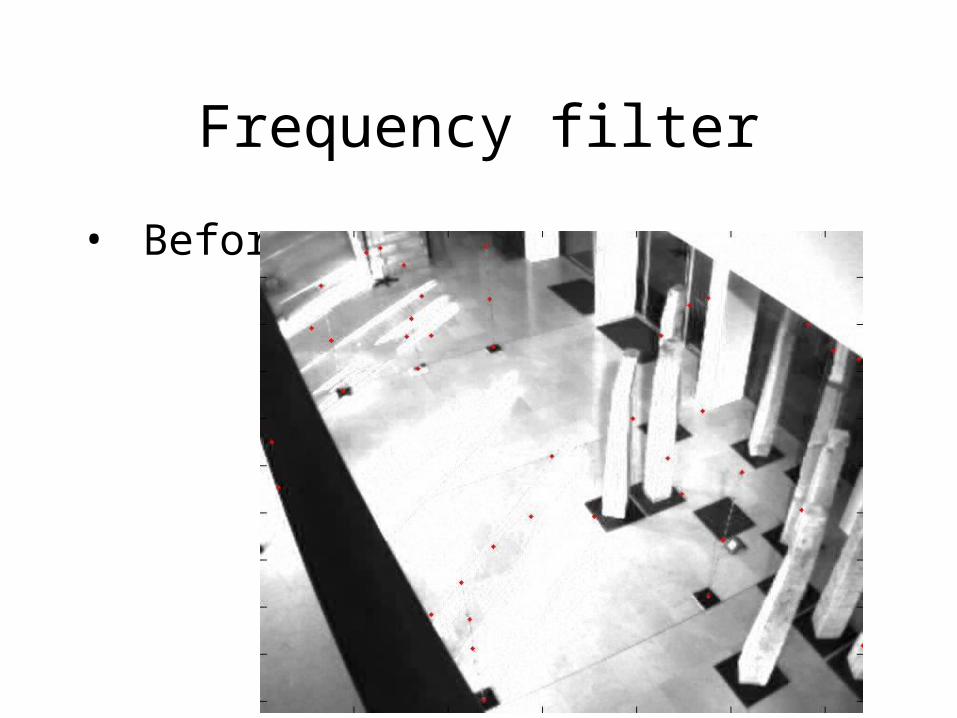
Frequency filter
• Before
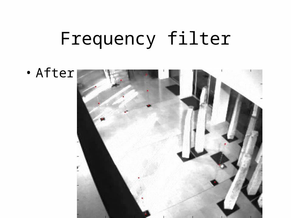
Frequency filter
• After
Detection method fourth stage
• Once we have the LED pixels detected we need to detect a pixel to represent it
• Local maximum, the pixel with the highest intensity level.
• Solution to different distances of camera from the features and different zoom rates.
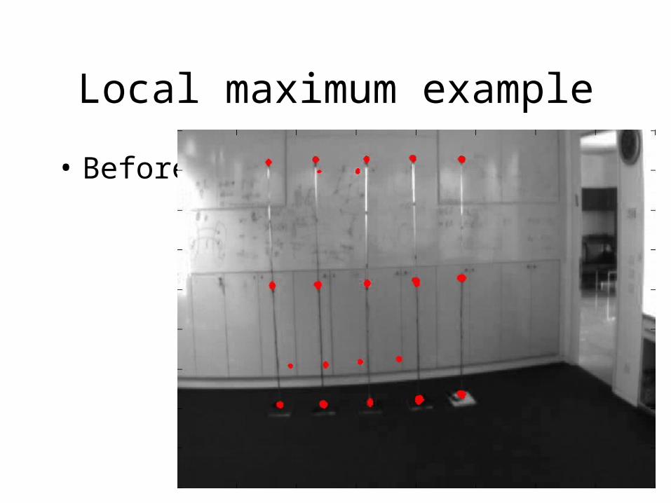
Local maximum example
• Before
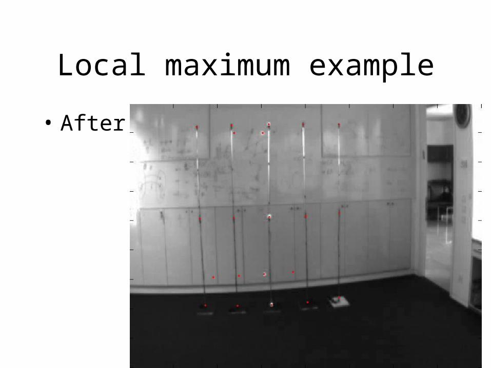
Local maximum example
• After
Full tool example
Synchronization
• Given the frame number k in the first camera find the corresponding frame in the second camera.
• Not all the cameras starts to film in the same time.
• Known solution using temporal features
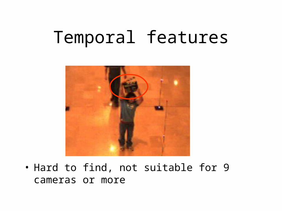
Temporal features
• Hard to find, not suitable for 9 cameras or more
Automatic synchronization
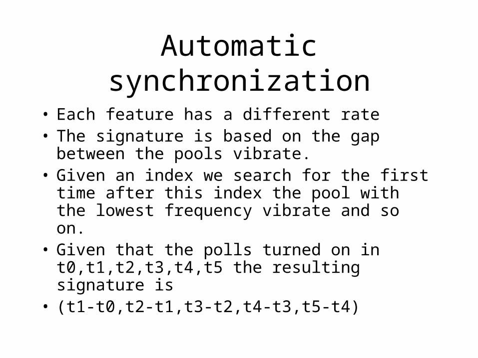
• Each feature has a different rate• The signature is based on the gap between the
pools vibrate.• Given an index we search for the first time after
this index the pool with the lowest frequency vibrate and so on.
• Given that the polls turned on in t0,t1,t2,t3,t4,t5 the resulting signature is
• (t1-t0,t2-t1,t3-t2,t4-t3,t5-t4)
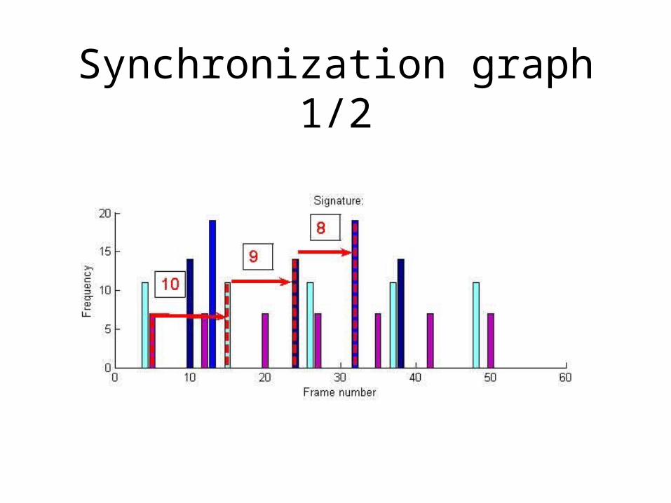
Synchronization graph 1/2
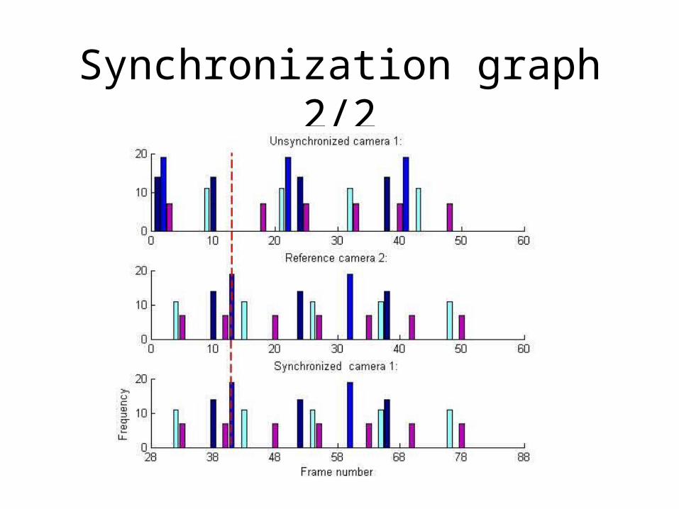
Synchronization graph 2/2
Tool synchronization example

The end
• Thank you!!!