Embed Size (px)
Citation preview

This manual is the property of the homeownerand must be left with the user.
� 2012 Lennox Industries Inc.
Dallas, Texas, USA
MS8ZMulti-Zone
Mini-Split SystemHeat Pumps
506968-01
10/2012Supersedes 5/2012

2
Warnings
WARNING
ELECTRICAL SHOCK, FIRE, OR EXPLOSION HAZARD.
Failure to follow safety warnings exactly could result in dangerous operation, serious injury, death or property damage.
Improper installation, adjustment, alteration, service or maintenancecan cause property damage, personal injury or loss of life. Installationand service must be performed by a licensed professional installer (orequivalent), or a service agency.
Any additions, changes, or conversions required in order for the appliance to satisfactorily meet the application needs must be made by alicensed professional installer (or equivalent) using factory-specifiedparts.
If you do not follow these instructions exactly, a fire or explosion mayresult causing property damage, personal injury or death.
For your safety and to fulfill the terms of the limited warranty, a licensedprofessional service technician (or equivalent) must annually inspectthis system.
This unit must be properly grounded.
Do not use this system if any part has been underwater. A flood-damaged appliance is extremely dangerous. Immediately call a licensedprofessional service technician (or equivalent) to inspect the systemand to replace all controls and electrical parts that have been wet or toreplace the system, if deemed necessary.
Keep combustible materials at least 3 feet away from either the indooror outdoor unit.
Do not insert your hands, tools or any other item into the air intake orair outlet at either the indoor or outdoor unit.
If outdoor unit is installed on a raised stand, check condition of standoccasionally to ensure that it remains stable.
DO NOT spray water on the indoor unit for any reason.
Do NOT install sprinkers or soaker hoses where they can expose theoutdoor unit to treated water. Prolonged exposure to treated water willcorrode the surface of the steel and aluminum parts and will diminishthe performance of the unit.

3
Parts Arrangement
Indoor unit
Outdoor units
Wall PipeWrapping Tape
Air inlet
(Typical indoor unit shown. Actual unit may be slightly different.)
Front Panel Display
Air outlet
Filter
Directional Louver
Wireless remote control
TemperatureHeating
Indoor Unit Display
Cooling Power/Run
Dehumidification
Receiver
Setting(or error code)
30 KBTU OUTDOOR UNIT(ONE TO FOUR ZONES)
18 KBTU OUTDOOR UNIT(ONE OR TWO ZONES)
24 KBTU OUTDOOR UNIT(ONE TO THREE ZONES
Important Operating Instructions
IMPORTANTTo ensure comfort, make sure that temperature selection has been properlyset at the remote control.
To ensure efficient operation, do not block air intake or outlet at either the indoor or outdoor unit.
Do not stand on outdoor unit or store items on top of unit.
Make sure that indoor unit directional louver is properly adjusted.

4
System Operation
Multi-Zone Operation
This multi-zone system consists of a single outdoorunit and two to four indoor units. Each zone is controlled separately by the remote control furnishedwith the indoor unit.
The operating mode is determined by the zone thatinitiates the first demand for heating or cooling.
If the system is energized and a heating demandhas been initiated by zone 1, an error code (E7) willbe displayed of the front panel of the indoor unit ofany zone trying to initiate a cooling demand. Thezone 1 remote (and remotes for other zones callingfor heating) must be powered off in order to allowthe system operating mode to switch to the coolingmode. Once the zone initiates the cooling demand,the mode will have to be reset in the same way toallow a heating demand in another zone. This situation occurs only when there are very different requirements in two or more zones in the system.
Cooling Operation
In the cooling mode, the indoor coil absorbs theheat from the room and transfers it to the outdoorcoil where it is discharged. The system cooling capacity is affected by the outdoor ambient temperature. The indoor fan operates continuously in theCOOL mode. The indoor unit directional louver isfixed in an upward position.
In cooling mode, the operating range of the outdoorunit is typically from 23°F (-5°C) to 118°F (48°C).
Heating Operation
The refrigerant flow is reversed during the heatingcycle. In this case, the outdoor coil absorbs the heatfrom outside and transfers it to the indoor coil whereit is discharged into the room. The system heatingcapacity is also limited by the available heat in theoutdoor ambient air.
In the HEAT mode, the indoor fan will remain OFFfor two minutes in the following instances:
� at the beginning of each heating cycle,
� after a defrost cycle has ended,
In the heating mode, the indoor blower will continueto operate for 60 seconds after the outdoor unit has
shut off. The indoor unit directional louver is fixed ina downward position.
In climates with very low winter temperatures, it maybe necessary to supplement heating by additionalmeans (space heater, fireplace, etc.).
In heating mode, the operating range of the outdoorunit is typically from 05°F (-15°C) to 80°F (27°C).
AUTO Mode Operation
When the system is set to operate in AUTO mode,the indoor and outdoor units work together to meeta series of preset demands. The remote controltemperature setpoint and fan operation functionsare not adjustable in the AUTO mode.
In AUTO mode, if the indoor ambient temperatureis greater than 77°F (25°C), the unit will operate inthe cooling mode. The outdoor unit will run until theindoor ambient temperature reaches 75°F (24°C).At this point, the outdoor unit compressor and outdoor fan will operate for another 60 seconds, thenthey will both turn off. The indoor fan will run continuously at a speed determined by the indoor ambienttemperature. During AUTO cooling operation, theindoor unit directional louver is fixed in an upwardposition.
Heat Pump Systems Only -- In AUTO mode, if theindoor ambient temperature is less than 68°F(20°C), the unit will run in heating mode. The outdoor unit will run until the indoor ambient temperature reaches 69°F (21°C). At this point, the outdoorunit compressor and fan will operate for another 60seconds, then they will both turn off. The indoor fanwill run continuously at a speed determined by theindoor ambient temperature. During AUTO heatingoperation, the indoor unit directional louver is fixedin a downward position.
FAN Mode Operation
When the system is set to operate in FAN mode, theindoor fan runs continuously in AUTO, low, mediumor high speed. The outdoor unit is off. In AUTO fanmode, the fan speed is determined by the indoorambient air temperature.
DEHUMIDIFICATION Mode Operation
When the system is set to operate in DEHUMIDIFICATION mode, the indoor fan runs continuously inlow speed.

5
Wireless Remote Functions
The wireless remote control provides system control to the homeowner at the touch of abutton. The indoor unit and remote control send information back and forth continuously.The remote control must be placed on a table or other surface in direct line of sight withthe indoor unit infrared receiver. The remote control should not be placed in a drawer.Make sure that there are no obstructions between the indoor unit receiver and the remotecontrol. Do not drop the control or spill liquid on the remote control.
POWER button
Press this button once to turnsystem on. Press again to turn the system off. When thePOWER button is used to turnthe system OFF, it overrides theSleep Timer function (when it isin use).
MODE button
Press this button to select systemoperating modes. AUTO mode isthe default setting. Press MODEbutton again to select COOL mode,again for DEHUMIDIFICATIONmode, again for FAN mode andagain for HEAT mode (heat pumpsonly).
Selected mode is displayed on bothremote and indoor unit cover panel.
+/- buttons
Use plus (+) and minus (-) buttons to adjust the temperaturesetting up and down.
NOTE - The temperature cannotbe adjusted when the system isin AUTO mode.
Press - and + buttons simultaneously to either lock or unlockthe remote control buttons.When the remote control islocked, the icon is displayed.
AUTO
COOL
DEHUMIDIFICATION
FAN
HEAT
FAN button
Press this button to select fanspeed. AUTO fan is the defaultsetting. In AUTO fan mode, theindoor fan speed is determinedby the indoor ambient temperature. Press FAN button to stepthrough FAN setting selections:AUTO, low speed, mediumspeed and high speed. Selected fan speed is shown atthe top of the remote control display.
NOTE - The fan speed is not adjustable during DEHUMIDIFICATION mode operation. Thelow fan speed is necessary to ensure optimal humiditycontrol.
AUTO
Low Medium High
UNUSED buttons
These buttons are not functional in the MS8Z system.
I FEEL button
Press the I FEEL button to activate the I FEEL feature. Whenthe I FEEL icon appears,temperature sensor in remotecontrol (rather than return airsensor in indoor unit) is used toinitiate heating or cooling demands. Press I FEEL buttonagain to cancel I FEEL featureand transfer room temperaturesensing back to return air sensorin indoor unit.
IMPORTANT - In I FEEL mode,remote control must be placedon a table or other surface in direct line of sight with the indoor unit infrared receiver.The control should not beplaced in a drawer. Make surethat there are no obstructionsbetween the indoor unit receiver and the remote control.Ensure proper operation ofunit before permanent installation of optional wall mountingbracket.
6
Wireless Remote Functions (Continued)
TURBO button
Use the TURBO button to initiate or cancel high-speed fanoperation to accelerate cooling or heating of the ambient roomtemperature. The turbo icon is displayed when the function isturned on.
CLOCK button
Use the CLOCK button to adjustthe time displayed on the remotecontrol. Press the CLOCK buttononce. The clock icon willflash. Within 2 seconds, use the- and + buttons to adjust the timedown or up in one-minute increments. Press the button continuously to adjust the time in10-minute increments. Press theCLOCK button again when correct time is displayed.
BLOW button
Use the BLOW button to extend low speed blower operation for 10 minutes at the end of a cooling demand.
The extended fan (BLOW) operation ensures that excessmoisture is removed from the indoor coil before the blowershuts off.
Press the BLOW button once toinitiate extended blower operation. Fan operation ends after 10minutes. The extended fan (BLOW) operation icon is displayedwhen the feature is turned on.
Extended fan (BLOW) operationis available in cooling or dehumidification modes; extended fan(BLOW) operation is not available in AUTO, heating or fanmode.
SWITCH FROM °C TO °F
With system OFF, press MODEand - buttons simultaneously toswitch from Centigrade to Fahrenheit. Current selection is displayed to the right of thetemperature display.
SLEEP button
Use the SLEEP button to initiateor cancel the sleep function.Press SLEEP button. Whensleep icon appears, pressTIMER OFF button and use -and + buttons to set time for system shutdown. When desiredtime is displayed, press TIMEROFF button again. Press SLEEPbutton to cancel sleep function.In cooling mode, SLEEP functionincreases temperature (+1.8°Fper hour) over a two-hour periodafter the selected sleep time.In heating mode, SLEEP functiondecreases temperature (-1.8°Fper hour) over a two-hour periodafter the selected sleep time.
NOTE - The sleep function is notavailable in AUTO or FANmodes.
TIMER ON button
Use the TIMER ON button to initiate or cancel a single timed-onevent. Use this feature to bringthe system on just before you return home or just before youwake in the morning.
Press the TIMER ON buttononce. The clock icon disappears and a time settingappears with the word ON flashing at the right. Use the - and +keys to adjust the time setting tothe desired time for the systemto begin operation. Press theTIMER ON button again to accept the setting. When successfully set, the word ON willappear to the right of the currenttime display. Press the TIMERON button again if you want tocancel the timed-on event.
TIMER OFF button
Use the TIMER OFF button toinitiate or cancel a single timed-off event. Use this feature to turnthe system off just after youleave the house or just after yougo to bed at night.
Use the same method described above to set the desired time for the system to stopoperation. When successfullyset, the word OFF will appear tothe right of the current time display. Press the TIMER OFF button again if you want to cancelthe timed-off event.
LIGHT button
Use the LIGHT button to turn theindoor unit display light on andoff. When the light is on, theicon appears on the remote control.

7
Wireless Remote Functions (Continued)
Press the TEMP button again todisplay the outdoor ambient temperature icon. The outdoorambient temperature display isnot available on this system.
On occasion, the remote controlwill display the temperature thatwas not selected (indoor ambienttemperature or setting temperature). The selected temperaturewill return to the display screenafter 5 seconds.
NOTE - The TEMP button canalso be used to temporarily display the indoor ambient temperature on the indoor unit displaypanel.
LOUVER SETTING button
Use the LOUVER SETTING button to choose a preferred louversetting, rather than the defaultsetting, during fan operation.Refer to the following section forlouver operation.
TEMP button
Use the TEMP button to changethe temperature display shownon the remote control. When initially powered on, the currenttemperature setting is displayed,along with the icon.
Press the TEMP button once to alter the display to show thecurrent indoor ambient temperature, along with the icon. Theindoor temperature sensor is inthe indoor unit.
Louver Operation
LOUVER SETTING button
Use the LOUVER SETTINGbutton to choose a preferredsetting for the indoor unitdirectional louver.
NOTE - Actual louverposition is different thanwhat is shown on remoteicon. See comparison tothe right.
Press the LOUVERSETTING button once toactivate the full-rangeoscillation mode from top tobottom, then back again. Thelouver icon will appear inthe lower section of thescreen.
Press the LOUVERSETTING button again toturn the feature OFF. Thelouver will return to thedefault setting.
Press the LOUVERSETTING button twice andcontinue to press the buttonto scroll through the fiveavailable fixed positions
AND three other oscillatingpositions.
o r a b o v e
REMOTECONTROL ICON
POSITION
ACTUALLOUVER
POSITION
To return the louver to thedefault position, press theLOUVER SETTING buttonuntil the icon disappears.
Default Louver Positions
When the louver setting iconis not displayed, the louver isin the DEFAULT position.
When the remote control ispowered OFF, the defaultposition is fully closed.
When the remote control isset so that the unit is inCOOLING, AUTO COOLING,or DEHUMIDIFICATIONmode, the louver is in a fixedupward position .
When the remote control isset so that the unit is in HEATor AUTO HEATING mode andthe outdoor unit is OFF, thelouver is fixed in the secondposition pointed upward. Ifthe outdoor unit is ON, thelouver is fixed in a downwardposition .
When the remote is set forcontinuous indoor fan to beON, the louver is fixed in anupward position .
LOUVERSETTING
ICON
8
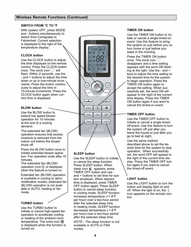
System Start Up Using Wireless Remote
General Operation
1 - Press POWER button once to turn system on.
2 - Press MODE button until desired operatingmode icon is displayed.
NOTE - When AUTO mode is selected, thetemperature setting is not displayed on theremote control. The - and + buttons cannot beused to make temperature setting selections.
3 - Press - or + buttons until desired temperaturesetting is displayed.
NOTE - Skip this step in AUTO mode.
4 - Press FAN button until desired fan speed iconis displayed.
NOTE - Fan speed will be set to low if DEHUMIDIFICATION mode has been selected.
5 - Press LOUVER SETTING button to controlindoor unit directional louver. Press once toactivate full range oscillation. Press more thanonce to scroll through and select one of fivefixed positions or one of three other oscillatingpositions. If function is activated when unitpowers off, preferred setting will be activatedagain when unit operation is restored.
Special Functions
6 - Press SLEEP button to initiate sleep function.Then press TIMER OFF button to set timedoff.
7 - Use TIMER ON and TIMER OFF buttons toschedule desired timed on and off settings.
8 - Use LIGHT button to set display light on oroff.
9 - Use BLOW button to turn on and off extendedfan operation feature.
10-Use TURBO button to turn accelerated fanspeed on or off.
11-Use I FEEL button to use temperature sensorin remote control (rather than return airsensor in indoor unit) to initiate cooling andheating demands.
1
2
3
4
5
7
8
9
10
6
11
9
Remote Control — Important Information
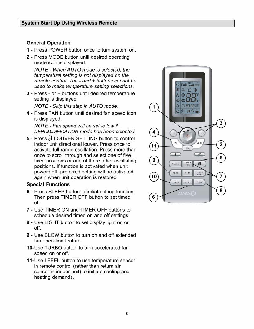
The wireless remote control requires two AAA, 1.5V batteries.DO NOT attempt to use any other type of battery.
Follow the steps below and in the illustrations to replace the batteries when necessary.
1 - Remove screw that secures the battery access panel to the remote. Place thumb on at the top of the battery access panel on the back of the remote control. Slide the panel in the direction of the arrow.
2 - Remove the existing AAA, 1.5V batteries.
3 - Replace batteries with fully charged AAA, 1.5V batteries.NOTE - Pay attention to proper polarity of batteries. Remote control will not operate if batteries are improperly installed.
4 - Reposition battery access panel and slide forward until panel snaps into locked position. Reinsert screw.
� Remote should remain within its receiving range to ensure proper system control. Control should be kept at least 3 feet (914mm) away from other electrical appliances(televisions, stereos, etc.) to prevent signal interference.
� If remote control operation becomes erratic, remove batteries. Wait 30 seconds andreinsert batteries. If proper remote operation is not restored, replace batteries.
SCREW
SCREW
IMPORTANT !
� If wireless remote will not be used for a long period of time, remove batteries to avoid damage to the control.
� To verify that the remote control is transmitting commands to the indoor unit, press any command key anda wireless icon will appear in the upper right-handcorner of the remote control display.
� When being used in the I FEEL mode, the remote control must be placed on a table or other surface in directline of sight with the indoor unit infrared receiver. Thecontrol should not be placed in a drawer. Make sure thatthere are no obstructions between the indoor unit receiver and the remote control.
10
Maintenance
WARNING!
Turn off all power to unit at system disconnect switch (at theoutdoor unit) or circuit breaker before performing any maintenance procedures! Failure to follow this warning could lead to personal injury or death.
Coil fins are very sharp! Take care not to touch the fins inorder to avoid injury.
Indoor Unit Filters
The indoor unit filter should be cleaned every three months, ormore frequently, if necessary.
Follow the steps below and in the illustrations to clean the filters.
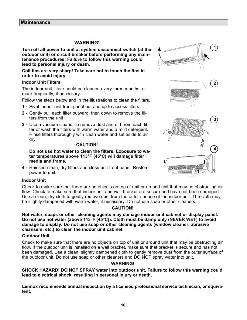
1 - Pivot indoor unit front panel out and up to access filters.
2 - Gently pull each filter outward, then down to remove the filters from the unit
3 - Use a vacuum cleaner to remove dust and dirt from each filter or wash the filters with warm water and a mild detergent.Rinse filters thoroughly with clean water and set aside to airdry.
CAUTION!
Do not use hot water to clean the filters. Exposure to water temperatures above 113°F (45°C) will damage filtermedia and frame.
4 - Reinsert clean, dry filters and close unit front panel. Restorepower to unit.
1
2
3
4
Indoor Unit
Check to make sure that there are no objects on top of unit or around unit that may be obstructing airflow. Check to make sure that indoor unit and wall bracket are secure and have not been damaged.Use a clean, dry cloth to gently remove dust from the outer surface of the indoor unit. The cloth maybe slightly dampened with warm water, if necessary. Do not use soap or other cleaners.
CAUTION!
Hot water, soaps or other cleaning agents may damage indoor unit cabinet or display panel.Do not use hot water (above 113°F [45°C]). Cloth must be damp only (NEVER WET) to avoiddamage to display. Do not use soap or other cleaning agents (window cleaner, abrasivecleansers, etc.) to clean the indoor unit cabinet.
Outdoor Unit
Check to make sure that there are no objects on top of unit or around unit that may be obstructing airflow. If the outdoor unit is installed on a wall bracket, make sure that bracket is secure and has notbeen damaged. Use a clean, slightly dampened cloth to gently remove dust from the outer surface ofthe outdoor unit. Do not use soap or other cleaners and DO NOT spray water into unit.
WARNING!
SHOCK HAZARD! DO NOT SPRAY water into outdoor unit. Failure to follow this warning couldlead to electrical shock, resulting in personal injury or death.
Lennox recommends annual inspection by a licensed professional service technician, or equivalent.
11
Troubleshooting
WARNING!
ELECTRICAL SHOCK HAZARD! Never attempt to repair the indoor or outdoor unit yourself. System repairs must be
performed by a licensed, professional technician, or equivalent.
If any of the following conditions exist, immediately turn the system (indoor and outdoor units) off at the unit disconnect
switch and call a licensed professional technician, or equivalent, for repairs
� There is a very loud sound during unit operation.
� There is a terrible odor coming from the indoor unit during operation.
� Water is leaking into the room.
� The circuit breaker trips frequently.
� Water or some other liquid has been splashed into the indoor unit.
If none of the above conditions exist, check the following items before calling for repairs. This can save you both time
and money.
Problem Possible Cause
Unit does not operate immediately when restarted.Unit control initiates a 3-minute delay at the end of each cycle to protectthe compressor from damage.
A whoosh or gurgling noise can be heard at the indoor unit.Sometimes, the refrigerant can be heard in the indoor coil when theoutdoor unit starts or stops operation. This is not a malfunction.
Mist is coming out of the indoor unit during cooling operation.This sometimes happens when the indoor temperature and humidity arevery high and the air is being cooled quickly. The mist will disappear asthe indoor temperature and humidity are lowered.
A creaking or popping noise can be heard when the unit starts or stops.The plastic components of the indoor units sometimes expand and contract when they are heated and cooled.
Unit is not operating.
Are the TIMER ON and TIMER OFF features being used incorrectly?
Is power disconnected or has circuit breaker tripped.
Is power shut down?
System is not cooling (or heating) efficiently.
Is temperature setting correct?
Are either the air inlet or air outlet blocked on the outdoor or indoor unit?
Is filter dirty?
Is fan at low speed?
Are windows and doors properly shut?
Wireless remote is not working.
Is remote in direct line of sight with indoor unit infrared receiver? Hasthe remote been damaged?
Remove remote control batteries for 30 seconds, then reinsert them.Replace batteries, if necessary.
Water is leaking from indoor unit.Indoor humidity level is very high and water is being blown from indoorcoil. This will stop as humidity level is reduced.
Water is leaking from condensate line at Water is leaking from condensate line at indoor unit.indoor unit.
Check condensate line outside to make sure it is not obstructed.
Check condensate line to make sure it has not been disconnected fromindoor unit.
Water is leaking from the outdoor unit.
During operation in high-humidity areas, condensate will form on coldoutdoor refrigerant pipes.
When heat pump is operating in defrost mode, ice will thaw from aroundoutdoor coil and water will flow from the unit.
Clicking noise heard inside.Sometimes, the sound of the outdoor unit fan or compressor relay canbe transmitted in a way that makes it seem to be coming from the indoorunit.
Indoor fan is not working.
Heat pump units -- In HEAT mode, a timed delay keeps indoor fan offfor two minutes to prevent unheated air from being circulated by theindoor fan.
Heat pump units -- In HEAT mode, cold outdoor temperatures and highhumidity cause frost to accumulate on the outdoor unit. When this happens, the unit will enter a defrost cycle. The indoor fan is off during the 3- 12 minute cycle.
In DEHUMIDIFICATION mode, indoor fan operation may be stopped toavoid delivery of moist air to the room. Do not adjust temperature setting.

12
Auto ON Switch
If the remote control is lost or damaged, or ifcharged AAA, 1.5V batteries are not available, the Auto ON switch can be used to turnthe system on or off.
The Auto ON switch is located behind thecover panel on the indoor unit. Lift the frontpanel and press the ON button once briefly tostart the system. To stop emergency operation, push the ON button again.
IMPORTANT !
The Auto ON button initiates operation inthe AUTO mode. The temperature and fanspeed are not adjustable in the AUTOmode.
AUTO
PENCIL OR OTHER
NON-METALLIC OBJECT
AUTO BUTTON
PRESS
WITH
FINGER
AUTO Switch(Recessed)
AUTO Switch(Not Recessed)
Error Codes
If a problem occurs with the system, an error code will replace the temperature setting displayed on
the front cover of the indoor unit. If more than one error has occurred, the codes will alternate so
that all codes are shown. Make note of the code (E4, F6, H4, etc.), then reset the display by pressing
the ON/OFF button on the wireless remote. Press the ON/OFF button a second time to reapply pow
er to system. If code is still displayed, disconnect and restore power at the unit disconnect switch
or circuit breaker. If the problem was temporary, the code will not reappear. If the error code re-ap
pears after power has been broken and restored at the disconnect switch or circuit breaker, call a
licensed professional service technician.
HE
AT
IN
DIC
AT
OR
CO
OL IN
DIC
AT
OR
TE
MP
ER
AT
UR
E*
RU
N
DE
HU
MID
IFY
MO
DE
INF
RA
RE
DS
IGN
AL
RE
CE
PT
OR* The temperature readout will be replaced
by an error code if there is a malfunction.
88


![MULTI CHANNEL AV RECEIVER STR-DN1070 · Using the Multi-Zone Features Overview of multi-zone features What you can do with multi-zone features [102] Available inputs for each zone](https://img.pdfslide.net/doc/110x75/5f56cb4c8b92cd26696ca96c/multi-channel-av-receiver-str-dn1070-using-the-multi-zone-features-overview-of-multi-zone.jpg)